EP3315919B1 - Vehicle presence detector - Google Patents
Vehicle presence detector Download PDFInfo
- Publication number
- EP3315919B1 EP3315919B1 EP17191558.0A EP17191558A EP3315919B1 EP 3315919 B1 EP3315919 B1 EP 3315919B1 EP 17191558 A EP17191558 A EP 17191558A EP 3315919 B1 EP3315919 B1 EP 3315919B1
- Authority
- EP
- European Patent Office
- Prior art keywords
- vector sensor
- input
- output
- block
- vector
- Prior art date
- Legal status (The legal status is an assumption and is not a legal conclusion. Google has not performed a legal analysis and makes no representation as to the accuracy of the status listed.)
- Active
Links
Images
Classifications
-
- G—PHYSICS
- G01—MEASURING; TESTING
- G01D—MEASURING NOT SPECIALLY ADAPTED FOR A SPECIFIC VARIABLE; ARRANGEMENTS FOR MEASURING TWO OR MORE VARIABLES NOT COVERED IN A SINGLE OTHER SUBCLASS; TARIFF METERING APPARATUS; MEASURING OR TESTING NOT OTHERWISE PROVIDED FOR
- G01D5/00—Mechanical means for transferring the output of a sensing member; Means for converting the output of a sensing member to another variable where the form or nature of the sensing member does not constrain the means for converting; Transducers not specially adapted for a specific variable
- G01D5/12—Mechanical means for transferring the output of a sensing member; Means for converting the output of a sensing member to another variable where the form or nature of the sensing member does not constrain the means for converting; Transducers not specially adapted for a specific variable using electric or magnetic means
- G01D5/14—Mechanical means for transferring the output of a sensing member; Means for converting the output of a sensing member to another variable where the form or nature of the sensing member does not constrain the means for converting; Transducers not specially adapted for a specific variable using electric or magnetic means influencing the magnitude of a current or voltage
- G01D5/142—Mechanical means for transferring the output of a sensing member; Means for converting the output of a sensing member to another variable where the form or nature of the sensing member does not constrain the means for converting; Transducers not specially adapted for a specific variable using electric or magnetic means influencing the magnitude of a current or voltage using Hall-effect devices
- G01D5/145—Mechanical means for transferring the output of a sensing member; Means for converting the output of a sensing member to another variable where the form or nature of the sensing member does not constrain the means for converting; Transducers not specially adapted for a specific variable using electric or magnetic means influencing the magnitude of a current or voltage using Hall-effect devices influenced by the relative movement between the Hall device and magnetic fields
-
- G—PHYSICS
- G01—MEASURING; TESTING
- G01V—GEOPHYSICS; GRAVITATIONAL MEASUREMENTS; DETECTING MASSES OR OBJECTS; TAGS
- G01V3/00—Electric or magnetic prospecting or detecting; Measuring magnetic field characteristics of the earth, e.g. declination, deviation
- G01V3/08—Electric or magnetic prospecting or detecting; Measuring magnetic field characteristics of the earth, e.g. declination, deviation operating with magnetic or electric fields produced or modified by objects or geological structures or by detecting devices
-
- G—PHYSICS
- G08—SIGNALLING
- G08G—TRAFFIC CONTROL SYSTEMS
- G08G1/00—Traffic control systems for road vehicles
- G08G1/01—Detecting movement of traffic to be counted or controlled
- G08G1/042—Detecting movement of traffic to be counted or controlled using inductive or magnetic detectors
Definitions
- the solution deals with contactless detection of a car presence by means of magnetic sensors, which is particularly advantageous for monitoring the occupancy of a parking space or for monitoring and controlling traffic.
- Contactless vehicle presence detection systems always use the appropriate physical sensor connected to the computing unit with an evaluation algorithm, either as a standalone detector or a whole network of detectors, for example for monitoring of parking lots.
- the key distinguishing criterion of these systems is the type of sensors used for detection of a car presence.
- Optical sensors such as light barriers or distance and image sensors or cameras are used.
- ultrasonic sensors are used also.
- Detection is advantageously provided by magnetic field sensors which, unlike ultrasonic and optical sensors, do not respond to the presence of people, are maintenance-free and resist the dusty environment.
- the magnetic field sensors use induction coils embedded, for example, in the road or floor.
- induction coils embedded, for example, in the road or floor.
- their major disadvantage is that they are not capable of stationary detection; only the arrival or departure of a car with a certain minimum speed is detected.
- Another embodiment uses vector sensors of the magnetic field, such as AMR, fluxgate, GMR, SDT.
- AMR magnetic field
- GMR magnetic field
- SDT magnetic field detector
- An overview of their parameters and applications is listed, for example, in the book Ripka, "Magnetic sensors and magnetometers", Artech House, 2001 .
- These vector sensors scan also the direct or very slowly variable component of the magnetic field. The sensors thus detect both the dynamic signal as in the case of the induction sensors and the stationary signal "car is present / absent".
- the disadvantage is that the direct and slowly variable magnetic field is generally unstable and is influenced by many surrounding factors such as steel structures, surrounding cars, changes in the Earth magnetic field, and similar. Therefore, a differential, i.e.
- gradiometric, arrangement of sensors is advantageously used to suppress interference, where two or more sensors located in the same direction are used for calculation of the difference of the measured signal, which to some extent suppresses distant, almost homogeneous interference, unlike the signal from the closest source of the magnetic moment, which is a car.
- the deployment of the detectors is limited to the location and orientation "under the vehicle" where the signature from the car is strongest.
- the drawback of current detectors is also their dimensions when in one embodiment where the sensors are placed under the car, the head size is approximately 40 cm.
- a vehicle detection block is used to process the signal from the sensors and to evaluate the presence of a vehicle, which can be defined as a computing unit with an evaluation algorithm that can be implemented, for example, as a software in microprocessor, programmable field array FPGA, or other computing means.
- the evaluation algorithm can, for instance, be some of the classification methods listed in the article Kiang, Melody Y, "A comparative assessment of classification methods", Decision Support Systems 35.4, 2003, pp. 441-454 .
- One of another possible evaluation algorithms is described in the patent CN105279975 (A) - 2016 " Non-standard parking detection method based on magnetic field sensor ".
- Another option to implement the evaluation algorithm is the neural network method, or searching in the symptom database or other methods described in Cox, D.
- the basic disadvantage of direct processing of the signal from the sensors by the methods mentioned above is the fact that the magnetic signature of a vehicle, that is, its magnetic moment, is not constant and therefore it is necessary to test and adaptively adjust the criteria of the above-mentioned classification methods, so-called "method learning", using sets of cars with different sizes, by different manufacturers, at different speeds, orientations, and similar.
- This detector includes a vehicle presence evaluation block that is equipped with software or hardware for evaluating the information from vector sensors, wherein both the vector sensors and the vehicle presence evaluation block are implemented by some of the known methods.
- the principle of the new solution is based on the fact that the detector comprises the first and the second vector sensor which are aligned in a straight line, they have parallel direction, and their vertical distance ranges from 2 cm to 20 cm.
- the output of both the first and second sensor enter a block calculating H/G as in prior art, which is in turn proportional to the distance to the vehicle.
- This function can be implemented either by hardware or software as described in prior art.
- This H/G distance evaluation block
- This H/G distance evaluation block
- the detector comprises an additional third and fourth vector sensor, which are orthogonal to the first (and thus also the second) vector sensor, and thus are forming and orthogonal triad, which enables to calculate the total value of the magnetic field which then enters the second input of the vehicle presence evaluation block.
- the vehicle presence detector is connected as follows.
- the output of the first vector sensor is connected to the input of the first block of converting the uncalibrated output values from this first vector sensor to the calibrated values.
- the sensitivity of the first sensor obtained by any of the known calibration methods described in the literature, is used for the conversion.
- the output of the first block of converting the uncalibrated output values from this first vector sensor to the calibrated values proportional to the magnetic flux density marked as B 1 is connected to both the first input of the summing circuit, and to the first input of the differential circuit.
- the output of the second vector sensor is connected to the input of the second block of converting the uncalibrated output values from the second vector sensor to the calibrated values proportional to the magnetic flux density indicated as B 2 , the sensitivity of the second sensor obtained analogically as for the first sensor is used for the conversion, and the output of this block is interconnected with both the second input of the summing circuit, and with the second input of the differential circuit.
- the summing circuit output is via the circuit for dividing by two interconnected with the first input of the divider.
- the output of the differential circuit is via the divider for dividing by number d, specifying the distance between the first and second vector sensors, connected to the second input of the divider, the output of which is connected to the input of the vehicle presence evaluation block.
- the third and fourth vector sensors together with the first vector sensor form a triad in an orthogonal configuration. Both the third and fourth vector sensors are connected to the relevant inputs of the magnetic field scalar value calculation block.
- the already calibrated value B1 of the first vector sensor is also connected to the magnetic field scalar value calculation block.
- the scalar value calculation block in the first step converts the uncalibrated values of the third and fourth sensors to the calibrated values marked as B3 and B4 and then performs the operation ⁇ (B12+B32+B42), which is a common procedure for determining the scalar value of a vector from three orthogonal components.
- the output of the magnetic field scalar value calculation block is interconnected with the above-mentioned second input of the vehicle presence evaluation block.
- Information about the scalar value is therefore used as an additional information for evaluation of the vehicle presence, which is advantageous for increasing the accuracy of a vehicle presence estimation.
- the noise of the first and second vector sensors is lower than 10 nT/ ⁇ Hz @ 1 Hz.
- the noise of the third and fourth vector sensors is lower than 10 nT/ ⁇ Hz @ 1 Hz.
- the detector is positioned relative to the assumed location of the car so that the line, on which the first and second vector sensors are located, is oriented towards the assumed occurrence of the car so that it is on that line. In such a case, the accuracy of the distance evaluation is greatest. The same applies to the arrangement with four vector sensors.
- the output of the vehicle presence evaluation block is interconnected with a control circuit equipped with software for collecting and evaluating the data via a sensor network, either as a standalone detector, or as multiple detectors connected to the sensor network.
- a suitable sensor network can be RS-485, CAN-BUS, Ethernet or some other commonly known bus.
- the advantage of the new solution is that the additional information about the total value of the Earths magnetic field, which is not dependent on the vehicle detector (and thus vector sensors) orientation, is provided.
- the detector is less sensitive to angular drifts, physical misalignments and also is to a large state immune to changes in the Earth's field. This then allows for an increased detection distance, since these effects are less pronounced when the detector is positioned just under the car as in present inventions .
- Also the total (scalar) value of magnetic field is no dependendt on the orientation of the magnetic dipole, which can represent the car magnetic moment, which is not constant in time and depends neither on the car type, make etc.
- detection is reliable also if, for example, right above the empty parking space, but one floor higher, that is on the ceiling, on which the described detector is attached, another vehicle is parked.
- the location on the side of the car is advantageous, for example, for applications used for the traffic analysis and management to determine the frequency of occurrence of vehicles at a junction, road, and the like.
- Positioning of the detector above the automobile also eliminates the major structural disadvantage of previous solutions with magnetic sensors, especially in underground car parking houses, where in the new embodiment it is possible to place the detector on the ceiling without any construction work on the floor or road.
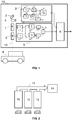
- FIG. 1 An embodiment of the detector in position above the parking space is shown in Fig. 1.
- Fig. 2 shows multiple detectors interconnected by means of a bus with a control circuit..
- FIG. 1 An example of a vehicle presence detector embodiment is shown in Fig. 1 .
- the detector comprises of a first vector sensor 1 and a second vector sensor 2 , which lie on one line 12 and have a concurrent direction, and of vector sensor 3 and the fourth vector sensor 4, which are arranged so that they form an orthogonal triad with the first vector sensor 1 (their directions cover all the coordinates of the Cartesian coordinate system).
- Their vertical distance between the first and second vector sensors 1 and 2 range from 2 cm to 20 cm and their noise is less than 10 nT/ ⁇ Hz @ 1 Hz.
- the block 5 of calculation of the vehicle distance from the detector is inserted.
- the interconnection is realized in such a way that the output of the first vector sensor 1 is connected to the input of the first block 51 of converting the uncalibrated output values from this first vector sensor 1 to the calibrated values.
- the output of the first converting block 51 is connected to both the first input of the summing circuit 52 , and to the first input of the differential circuit 55 .
- the output of the second vector sensor 2 is connected to the input of the second block 54 of converting the uncalibrated output values from the second vector sensor 2 to the calibrated values.
- the output of the second converting block 54 is connected to both the second input of the summing circuit 52 , and to the second input of the differential circuit 55 .
- the output of the summing circuit 52 is via the circuit 53 for dividing by two interconnected with the first input of the divider 57 .
- the output of the differential circuit 55 is via the divider 56 for dividing by number d specifying the distance between the first vector sensor 1 and the second vector sensor 2 connected to the second input of the divider 57 , the output of which is connected to the first input of the vehicle presence evaluation block 6 , while its output 7 will provide the information whether a vehicle 8 is present or not.
- the first vector sensor 1 and the second vector sensor 2 respectively measure the magnetic field, which results in uncalibrated values obtained at their outputs. These are then converted to calibrated values in the first converting block 51 and the second converting block 54 respectively by dividing by the sensitivity S 1 of the first vector sensor 1 and by the sensitivity S 2 of the second vector sensor 2 respectively. These sensitivities are obtained by calibrating the respective sensor, which is well known and described in the literature.
- the output of the first converting block 51 then is the information about the magnitude of the magnetic flux density B 1 already represented in the physical units (T) detected by the first vector sensor 1 at the point where it is located.
- the output of the second converting block 54 is the information about the magnitude of the magnetic flux density B 2 detected by the second vector sensor 2 at the point where it is located.
- values B 1 and B 2 are summed in the summing circuit 52 and subsequently they are divided by two in the dividing circuit 53 for dividing by two to produce their mean value, i.e. the output is the information about the homogeneous component of the field H, and is therefore an estimate of the magnetic flux density in the center on line 12 between the first vector sensor 1 and the second vector sensor 2 .
- Differential circuit 55 implements the difference of magnetic flux densities B 1 and B 2 , no matter in which order.
- the output of the differential circuit 55 is led to the divider 56 where it is divided by the number d , which indicates the distance between the first vector sensor 1 and the second vector sensor 2 .
- the output of the divider 56 is the information about the gradient component of the field G, which is an estimate of the magnetic flux density gradient again in the center of line 12 between the first vector sensor 1 and the second vector sensor 2 .
- Information about the detected homogeneous component H and the gradient component G is led to the input of the divider 57 , where the function (H/G) is performed, which at the output of the block 5 of calculation of the vehicle distance from the detector specifies the information L, which is proportional to the distance of the vehicle 8 from the detector 10 .
- This information enters the vehicle presence evaluation block 6 where some of the commonly known method is implemented to provide the decision whether a vehicle is present, such as thresholding at a certain level, a database system, neural networks, and so on.
- a magnetic field scalar value calculation block 9 processes the information from vector sensors 1 , 3 and 4 .
- the output of the third vector sensor 3 is interconnected with one input of the magnetic field scalar value calculation block 9 ⁇ (B12+B32+B42), where B 1 , B 3 , and B 4 are the magnitudes of the magnetic flux density measured by the corresponding vector sensor 1 , 3 , 4 , while its second input is interconnected with the output of the fourth vector sensor 4 .
- the third input of the magnetic field scalar value calculation block 9 is connected to the output of the first block 51 of converting the uncalibrated output values from the first vector sensor 1 to the calibrated values of the block 5 of calculation of the vehicle distance from the detector.
- the output of the magnetic field scalar value calculation block 9 is interconnected with the second input of the vehicle presence evaluation block 6 .
- the implementation of the magnetic field scalar value calculation block 9 is quite common. It consists of a third block 91 of converting the uncalibrated output values from the third vector sensor 3 to the calibrated values, and its output is via the first circuit 92 of the second power connected to the first input of the block 96 of the square root of the sum. Further, it comprises the fourth block 93 of converting the uncalibrated output values from the fourth vector sensor 4 to the calibrated values, and its output is via the second circuit 94 of the second power connected to the second input of the block 96 of the square root of the sum.
- the output of the first block 51 of converting the uncalibrated output values from the first vector sensor 1 to the calibrated values is via the third circuit 95 of the second power connected to the third input of the block 96 of the square root of the sum.
- the output of the block 96 of the square root of the sum is connected to the second input of the vehicle presence evaluation block 6 .
- the information about the vector scalar value obtained from the first vector sensor 1 , the third vector sensor 3 and the fourth vector sensor 4 in the magnetic field scalar value calculation block 9 then serves as a secondary information for improving the classification.
- FIG. 3 Another possible improvement is the embodiment where the individual vehicle presence detectors are interconnected in a shared distributed network, which is serving, for example, for detecting the occupancy of parking spaces on a large parking lot.
- three vehicle presence detectors 10 are connected by means of a sensor network 13 to the control circuit 14 .
- the vehicle presence detector can be used to facilitate the management of parking spaces in shopping malls, parking houses, public spaces and also private parking lots, and it can be further used for the traffic regulation and analysis, etc.
Landscapes
- Physics & Mathematics (AREA)
- General Physics & Mathematics (AREA)
- Engineering & Computer Science (AREA)
- Remote Sensing (AREA)
- Life Sciences & Earth Sciences (AREA)
- Electromagnetism (AREA)
- Environmental & Geological Engineering (AREA)
- Geology (AREA)
- General Life Sciences & Earth Sciences (AREA)
- Geophysics (AREA)
- Traffic Control Systems (AREA)
- Geophysics And Detection Of Objects (AREA)
Description
- The solution deals with contactless detection of a car presence by means of magnetic sensors, which is particularly advantageous for monitoring the occupancy of a parking space or for monitoring and controlling traffic.
- Contactless vehicle presence detection systems always use the appropriate physical sensor connected to the computing unit with an evaluation algorithm, either as a standalone detector or a whole network of detectors, for example for monitoring of parking lots. The key distinguishing criterion of these systems is the type of sensors used for detection of a car presence. Optical sensors such as light barriers or distance and image sensors or cameras are used. For example, ultrasonic sensors are used also.
- Detection is advantageously provided by magnetic field sensors which, unlike ultrasonic and optical sensors, do not respond to the presence of people, are maintenance-free and resist the dusty environment.
- In one embodiment, the magnetic field sensors use induction coils embedded, for example, in the road or floor. However, their major disadvantage is that they are not capable of stationary detection; only the arrival or departure of a car with a certain minimum speed is detected.
- Another embodiment uses vector sensors of the magnetic field, such as AMR, fluxgate, GMR, SDT. An overview of their parameters and applications is listed, for example, in the book Ripka, "Magnetic sensors and magnetometers", Artech House, 2001. These vector sensors scan also the direct or very slowly variable component of the magnetic field. The sensors thus detect both the dynamic signal as in the case of the induction sensors and the stationary signal "car is present / absent". However, the disadvantage is that the direct and slowly variable magnetic field is generally unstable and is influenced by many surrounding factors such as steel structures, surrounding cars, changes in the Earth magnetic field, and similar. Therefore, a differential, i.e. gradiometric, arrangement of sensors is advantageously used to suppress interference, where two or more sensors located in the same direction are used for calculation of the difference of the measured signal, which to some extent suppresses distant, almost homogeneous interference, unlike the signal from the closest source of the magnetic moment, which is a car. However, due to the low sensitivity of the sensors used and the detection methods, the deployment of the detectors is limited to the location and orientation "under the vehicle" where the signature from the car is strongest. The drawback of current detectors is also their dimensions when in one embodiment where the sensors are placed under the car, the head size is approximately 40 cm.
- In a prior art, as described in patent application
EP0829736A3 "Verfahren zum Messen von Verzerrungen des Erdmagnetfeldes und Objektsensor zur Durchführung des Verfahrens" both homogeneous and gradiometric measurements utilizing two or more sensors are proposed, whereas the sensors can be in-line and the homogeneous field calculated as an average of the two sensors, and the gradient estimated as the difference (it can be also divided by the distance of the two sensors to have the estimation in physical units). It has been also described that it is advantageous to have a short distance between the two sensors, which reflects the fact that at a shorter distance the noise of the available sensors is manifested, and at a greater distance, the magnetic field gradient cannot be measured with sufficient accuracy considering that the typical distance of the detector from the vehicle is less than 1 m. - In all existing embodiments, a vehicle detection block is used to process the signal from the sensors and to evaluate the presence of a vehicle, which can be defined as a computing unit with an evaluation algorithm that can be implemented, for example, as a software in microprocessor, programmable field array FPGA, or other computing means. The evaluation algorithm can, for instance, be some of the classification methods listed in the article Kiang, Melody Y, "A comparative assessment of classification methods", Decision Support Systems 35.4, 2003, pp. 441-454. One of another possible evaluation algorithms is described in the patent
CN105279975 (A) - 2016 "Non-standard parking detection method based on magnetic field sensor". Another option to implement the evaluation algorithm is the neural network method, or searching in the symptom database or other methods described in Cox, D. R. & E. J. Snell, "Analysis of binary data", 1999. The magnetic signature of a vehicle, that is, its magnetic moment, is not constant and therefore it is necessary to test and adaptively adjust the criteria of the above-mentioned classification methods, so-called "method learning", using sets of cars with different sizes, by different manufacturers, at different speeds, orientations, and similar. - However, the basic disadvantage of direct processing of the signal from the sensors by the methods mentioned above is the fact that the magnetic signature of a vehicle, that is, its magnetic moment, is not constant and therefore it is necessary to test and adaptively adjust the criteria of the above-mentioned classification methods, so-called "method learning", using sets of cars with different sizes, by different manufacturers, at different speeds, orientations, and similar.
- The setbacks mentioned above are eliminated by the presented vehicle presence detector with vector sensors of the magnetic field, which is compact, sensitive and selective. This detector includes a vehicle presence evaluation block that is equipped with software or hardware for evaluating the information from vector sensors, wherein both the vector sensors and the vehicle presence evaluation block are implemented by some of the known methods. The principle of the new solution is based on the fact that the detector comprises the first and the second vector sensor which are aligned in a straight line, they have parallel direction, and their vertical distance ranges from 2 cm to 20 cm. The output of both the first and second sensor enter a block calculating H/G as in prior art, which is in turn proportional to the distance to the vehicle. This function can be implemented either by hardware or software as described in prior art. This H/G (distance evaluation block) is inserted between the first and second vector sensor outputs and the first input of the vehicle presence evaluation block.
- The principle of the new solution is based on the fact that the detector comprises an additional third and fourth vector sensor, which are orthogonal to the first (and thus also the second) vector sensor, and thus are forming and orthogonal triad, which enables to calculate the total value of the magnetic field which then enters the second input of the vehicle presence evaluation block.
- The vehicle presence detector is connected as follows. The output of the first vector sensor is connected to the input of the first block of converting the uncalibrated output values from this first vector sensor to the calibrated values. The sensitivity of the first sensor, obtained by any of the known calibration methods described in the literature, is used for the conversion. The output of the first block of converting the uncalibrated output values from this first vector sensor to the calibrated values proportional to the magnetic flux density marked as B1 is connected to both the first input of the summing circuit, and to the first input of the differential circuit. Simultaneously, the output of the second vector sensor is connected to the input of the second block of converting the uncalibrated output values from the second vector sensor to the calibrated values proportional to the magnetic flux density indicated as B2, the sensitivity of the second sensor obtained analogically as for the first sensor is used for the conversion, and the output of this block is interconnected with both the second input of the summing circuit, and with the second input of the differential circuit.
- The summing circuit output is via the circuit for dividing by two interconnected with the first input of the divider. The output of the differential circuit is via the divider for dividing by number d, specifying the distance between the first and second vector sensors, connected to the second input of the divider, the output of which is connected to the input of the vehicle presence evaluation block. The output of this divider and simultaneously the input of the vehicle presence evaluation block is therefore the signal L=H/G, where H was obtained as (B1+B2)/2 and G as (B1-B2)/d.
- The third and fourth vector sensors together with the first vector sensor form a triad in an orthogonal configuration. Both the third and fourth vector sensors are connected to the relevant inputs of the magnetic field scalar value calculation block. The already calibrated value B1 of the first vector sensor is also connected to the magnetic field scalar value calculation block. The scalar value calculation block in the first step converts the uncalibrated values of the third and fourth sensors to the calibrated values marked as B3 and B4 and then performs the operation √(B12+B32+B42), which is a common procedure for determining the scalar value of a vector from three orthogonal components.
- The output of the magnetic field scalar value calculation block is interconnected with the above-mentioned second input of the vehicle presence evaluation block. Information about the scalar value is therefore used as an additional information for evaluation of the vehicle presence, which is advantageous for increasing the accuracy of a vehicle presence estimation.
- Further, it is advantageous if the noise of the first and second vector sensors is lower than 10 nT/√Hz @ 1 Hz. Analogically, it is advantageous if the noise of the third and fourth vector sensors is lower than 10 nT/√Hz @ 1 Hz.
- In another preferred embodiment, the detector is positioned relative to the assumed location of the car so that the line, on which the first and second vector sensors are located, is oriented towards the assumed occurrence of the car so that it is on that line. In such a case, the accuracy of the distance evaluation is greatest. The same applies to the arrangement with four vector sensors.
- Further, it is advantageous if the output of the vehicle presence evaluation block is interconnected with a control circuit equipped with software for collecting and evaluating the data via a sensor network, either as a standalone detector, or as multiple detectors connected to the sensor network. A suitable sensor network can be RS-485, CAN-BUS, Ethernet or some other commonly known bus.
- The advantage of the new solution is that the additional information about the total value of the Earths magnetic field, which is not dependent on the vehicle detector (and thus vector sensors) orientation, is provided. Thus the detector is less sensitive to angular drifts, physical misalignments and also is to a large state immune to changes in the Earth's field. This then allows for an increased detection distance, since these effects are less pronounced when the detector is positioned just under the car as in present inventions .Also the total (scalar) value of magnetic field is no dependendt on the orientation of the magnetic dipole, which can represent the car magnetic moment, which is not constant in time and depends neither on the car type, make etc.
- With the presented detection, detection is reliable also if, for example, right above the empty parking space, but one floor higher, that is on the ceiling, on which the described detector is attached, another vehicle is parked. In this case, we have both the scalar field but also the vectorial information about H, G and the calculated distance, thus false detection of the car presence is decreased. The location on the side of the car is advantageous, for example, for applications used for the traffic analysis and management to determine the frequency of occurrence of vehicles at a junction, road, and the like. Positioning of the detector above the automobile also eliminates the major structural disadvantage of previous solutions with magnetic sensors, especially in underground car parking houses, where in the new embodiment it is possible to place the detector on the ceiling without any construction work on the floor or road.
- The presented solution will be further described with reference to the attached drawings. An embodiment of the detector in position above the parking space is shown in
Fig. 1. Fig. 2 shows multiple detectors interconnected by means of a bus with a control circuit.. - An example of a vehicle presence detector embodiment is shown in
Fig. 1 . The detector comprises of afirst vector sensor 1 and asecond vector sensor 2, which lie on oneline 12 and have a concurrent direction, and ofvector sensor 3 and thefourth vector sensor 4, which are arranged so that they form an orthogonal triad with the first vector sensor 1 (their directions cover all the coordinates of the Cartesian coordinate system). Their vertical distance between the first andsecond vector sensors - Between the outputs of the
first vector sensor 1 and thesecond vector sensor 2 and the input of the vehiclepresence evaluation block 6, theblock 5 of calculation of the vehicle distance from the detector is inserted. The interconnection is realized in such a way that the output of thefirst vector sensor 1 is connected to the input of thefirst block 51 of converting the uncalibrated output values from thisfirst vector sensor 1 to the calibrated values. The output of the first convertingblock 51 is connected to both the first input of the summing circuit 52, and to the first input of thedifferential circuit 55. Similarly, the output of thesecond vector sensor 2 is connected to the input of thesecond block 54 of converting the uncalibrated output values from thesecond vector sensor 2 to the calibrated values. The output of the second convertingblock 54 is connected to both the second input of the summing circuit 52, and to the second input of thedifferential circuit 55. The output of the summing circuit 52 is via thecircuit 53 for dividing by two interconnected with the first input of thedivider 57. The output of thedifferential circuit 55 is via the divider 56 for dividing by number d specifying the distance between thefirst vector sensor 1 and thesecond vector sensor 2 connected to the second input of thedivider 57, the output of which is connected to the first input of the vehiclepresence evaluation block 6, while its output 7 will provide the information whether avehicle 8 is present or not. - The
first vector sensor 1 and thesecond vector sensor 2 respectively measure the magnetic field, which results in uncalibrated values obtained at their outputs. These are then converted to calibrated values in the first convertingblock 51 and the second convertingblock 54 respectively by dividing by the sensitivity S1 of thefirst vector sensor 1 and by the sensitivity S2 of thesecond vector sensor 2 respectively. These sensitivities are obtained by calibrating the respective sensor, which is well known and described in the literature. The output of the first convertingblock 51 then is the information about the magnitude of the magnetic flux density B 1 already represented in the physical units (T) detected by thefirst vector sensor 1 at the point where it is located. Similarly, the output of the second convertingblock 54 then is the information about the magnitude of the magnetic flux density B 2 detected by thesecond vector sensor 2 at the point where it is located. Thus obtained values B 1 and B 2 are summed in the summing circuit 52 and subsequently they are divided by two in the dividingcircuit 53 for dividing by two to produce their mean value, i.e. the output is the information about the homogeneous component of the field H, and is therefore an estimate of the magnetic flux density in the center online 12 between thefirst vector sensor 1 and thesecond vector sensor 2.Differential circuit 55 implements the difference of magnetic flux densities B 1 and B 2 , no matter in which order. The output of thedifferential circuit 55 is led to the divider 56 where it is divided by the number d, which indicates the distance between thefirst vector sensor 1 and thesecond vector sensor 2. The output of the divider 56 is the information about the gradient component of the field G, which is an estimate of the magnetic flux density gradient again in the center ofline 12 between thefirst vector sensor 1 and thesecond vector sensor 2. Information about the detected homogeneous component H and the gradient component G is led to the input of thedivider 57, where the function (H/G) is performed, which at the output of theblock 5 of calculation of the vehicle distance from the detector specifies the information L, which is proportional to the distance of thevehicle 8 from thedetector 10. - This information enters the vehicle
presence evaluation block 6 where some of the commonly known method is implemented to provide the decision whether a vehicle is present, such as thresholding at a certain level, a database system, neural networks, and so on. - A magnetic field scalar
value calculation block 9 processes the information fromvector sensors third vector sensor 3 is interconnected with one input of the magnetic field scalarvalue calculation block 9 √(B12+B32+B42), where B1, B3, and B4 are the magnitudes of the magnetic flux density measured by the correspondingvector sensor fourth vector sensor 4. The third input of the magnetic field scalarvalue calculation block 9 is connected to the output of thefirst block 51 of converting the uncalibrated output values from thefirst vector sensor 1 to the calibrated values of theblock 5 of calculation of the vehicle distance from the detector. The output of the magnetic field scalarvalue calculation block 9 is interconnected with the second input of the vehiclepresence evaluation block 6. The implementation of the magnetic field scalarvalue calculation block 9 is quite common. It consists of athird block 91 of converting the uncalibrated output values from thethird vector sensor 3 to the calibrated values, and its output is via thefirst circuit 92 of the second power connected to the first input of theblock 96 of the square root of the sum. Further, it comprises thefourth block 93 of converting the uncalibrated output values from thefourth vector sensor 4 to the calibrated values, and its output is via thesecond circuit 94 of the second power connected to the second input of theblock 96 of the square root of the sum. The output of thefirst block 51 of converting the uncalibrated output values from thefirst vector sensor 1 to the calibrated values is via thethird circuit 95 of the second power connected to the third input of theblock 96 of the square root of the sum. The output of theblock 96 of the square root of the sum is connected to the second input of the vehiclepresence evaluation block 6. The information about the vector scalar value obtained from thefirst vector sensor 1, thethird vector sensor 3 and thefourth vector sensor 4 in the magnetic field scalarvalue calculation block 9 then serves as a secondary information for improving the classification. - Another possible improvement is the embodiment where the individual vehicle presence detectors are interconnected in a shared distributed network, which is serving, for example, for detecting the occupancy of parking spaces on a large parking lot. In Fig. 3, three
vehicle presence detectors 10 are connected by means of asensor network 13 to thecontrol circuit 14. - The vehicle presence detector can be used to facilitate the management of parking spaces in shopping malls, parking houses, public spaces and also private parking lots, and it can be further used for the traffic regulation and analysis, etc.
Claims (3)
- Vehicle presence detector comprising vector sensors of magnetic field and a vehicle presence evaluation block (6) equipped with software or hardware for evaluating the information from the vector sensors, wherein a first vector sensor (1) and a second vector sensor (2) sensitive directions lie on a single line (12), they have parallel direction and their vertical distance ranges from 2 cm to 20 cm, and between the outputs of the first vector sensor (1) and the second vector sensor (2) and the input of the vehicle presence evaluation block (6) is inserted a block (5) of calculation of the vehicle distance from the detector such that the output of the first vector sensor (1) is connected to the input of a first block (51) for converting the uncalibrated output values from the first vector sensor (1) to the calibrated values proportional to the magnetic flux density, the output of which is connected both to a first input of a summing circuit (52), and to a first input of a differential circuit (55), and simultaneously the output of the second vector sensor (2) is connected to an input of a second block (54) for converting the uncalibrated output values from the second vector sensor (2) to the calibrated values proportional to the magnetic flux density, the output of which is connected both to a second input of the summing circuit (52), and to a second input of the differential circuit (55), while the output of the summing circuit (52) is interconnected with the first input of the divider (57) via a circuit (53) for dividing by number two and the output of the differential circuit (55) is connected to the second input of the divider (57) via a further divider (56) for dividing by a number d specifying the distance between the first vector sensor (1) and the second vector sensor (2), the output of the divider (57) is connected to a first input of the vehicle presence evaluation block (6) characterized by the fact that it comprises a third vector sensor (3) and a fourth vector sensor (4), which form together with the first vector sensor (1) a triad in orthogonal configuration, and their outputs enter a magnetic field scalar value calculation block (9) realizing the function √(B12+B32+B42), where B1, B3, and B4 are calibrated values proportional to the magnetic flux density measured by the corresponding vector sensor (1,3,4), in such a way that the ouput of the third vector sensor (3) is interconnected with the first input of the scalar calculation block (9), while its second input is interconnected with the output of the fourth vector sensor (4), and its third input is interconnected with the output of the first block (51) for converting the uncalibrated output values from the first vector sensor (1) to the calibrated values proportional to the magnetic flux density of the block (5) of calculation of the vehicle distance from the detector, while the output of the magnetic field scalar value calculation block (9) is interconnected with a second input of the vehicle presence evaluation block (6).
- Detector according to claim 1 characterized by the fact that the noise of the third vector sensor (3) and the fourth vector sensor (4) is less 10 nT/√Hz @ 1 Hz.
- Detector according to any of claims 1 to 2 characterized by the fact that the output of the vehicle presence evaluation block (6) is interconnected with the control circuit (14) equipped with the software for data collection and assessment by means of sensor network (13), either individually, or with multiple detectors implemented.
Applications Claiming Priority (1)
| Application Number | Priority Date | Filing Date | Title |
|---|---|---|---|
| CZ2016-673A CZ2016673A3 (en) | 2016-10-31 | 2016-10-31 | A vehicle presence detector |
Publications (2)
| Publication Number | Publication Date |
|---|---|
| EP3315919A1 EP3315919A1 (en) | 2018-05-02 |
| EP3315919B1 true EP3315919B1 (en) | 2019-10-09 |
Family
ID=59901417
Family Applications (1)
| Application Number | Title | Priority Date | Filing Date |
|---|---|---|---|
| EP17191558.0A Active EP3315919B1 (en) | 2016-10-31 | 2017-09-18 | Vehicle presence detector |
Country Status (2)
| Country | Link |
|---|---|
| EP (1) | EP3315919B1 (en) |
| CZ (1) | CZ2016673A3 (en) |
Family Cites Families (10)
| Publication number | Priority date | Publication date | Assignee | Title |
|---|---|---|---|---|
| US4559713A (en) * | 1982-02-24 | 1985-12-24 | Applied Technologies Associates | Azimuth determination for vector sensor tools |
| EP0740279A1 (en) * | 1995-04-25 | 1996-10-30 | POWER MAGNETICS & ELECTRONIC SYSTEMS LIMITED | Vehicle presence detection system |
| EP0829736A3 (en) * | 1996-09-13 | 1999-12-01 | MetaPhysics S.A. | Measuring earth magnetic field distorsions and object sensor embodying the method |
| DE10048362C2 (en) * | 2000-09-29 | 2003-05-15 | Reinhard Zachmann | Method and arrangement for capturing traffic data by means of detection and classification of moving or stationary vehicles |
| CN201084279Y (en) * | 2007-08-08 | 2008-07-09 | 中科院嘉兴中心微系统所分中心 | A wireless sensor network device that detects traffic volume by using GMR sensor |
| US20100134322A1 (en) * | 2008-12-02 | 2010-06-03 | Electronics And Telecommunications Research Institute | Apparatus and method for detecting vehicles |
| CN101982734A (en) * | 2010-10-29 | 2011-03-02 | 南昌航空大学 | Calculation method for underground magnetic navigation |
| US9606195B2 (en) * | 2013-03-03 | 2017-03-28 | Bar Ilan University | High resolution planar hall effect sensors having plural orientations and method of operating the same to measure plural magnetic field components |
| WO2015040156A1 (en) * | 2013-09-19 | 2015-03-26 | Universitat Autonoma De Barcelona | A method and a portable rescue device for locating avalanche victims |
| GB2518384A (en) * | 2013-09-19 | 2015-03-25 | Univ Barcelona Autonoma | A method and a portable rescue device for locating avalanche victims |
-
2016
- 2016-10-31 CZ CZ2016-673A patent/CZ2016673A3/en not_active IP Right Cessation
-
2017
- 2017-09-18 EP EP17191558.0A patent/EP3315919B1/en active Active
Non-Patent Citations (1)
| Title |
|---|
| None * |
Also Published As
| Publication number | Publication date |
|---|---|
| CZ307060B6 (en) | 2017-12-20 |
| EP3315919A1 (en) | 2018-05-02 |
| CZ2016673A3 (en) | 2017-12-20 |
Similar Documents
| Publication | Publication Date | Title |
|---|---|---|
| JP5068546B2 (en) | Magnetic traffic control system | |
| Ali et al. | A multiple inductive loop vehicle detection system for heterogeneous and lane-less traffic | |
| CN101535843B (en) | Metal object detecting apparatus | |
| US20110199077A1 (en) | Ferrous object detector | |
| JP6928307B2 (en) | Marker detection system and marker detection method | |
| AU4281899A (en) | Apparatus for detecting metals | |
| CA2739584A1 (en) | System and method for detection of concealed cargo in a vehicle by center of mass measurement | |
| JP2013182551A (en) | Own vehicle position detection device, own vehicle position detection system and own vehicle position detection method | |
| JP2017524132A (en) | Method for identifying at least one object in a surrounding area of a motor vehicle by means of an ultrasonic sensor, a driver assistance system and a motor vehicle | |
| CN102194102A (en) | Method and device for classifying a traffic sign | |
| CN107657817A (en) | A kind of vehicle condition detection device based on more geomagnetic sensors | |
| CN106645799A (en) | Parameter calibration method and apparatus | |
| EP3929689A1 (en) | Magnetic marker diagnostic system and diagnostic method | |
| JP4979306B2 (en) | Vehicle automatic measurement device, vehicle automatic measurement system, and vehicle automatic measurement method | |
| US20220317238A1 (en) | Vessel analysis device, vessel behavior learning device, vessel analysis system, vessel analysis method, vessel behavior learning method, and recording medium | |
| TW202030492A (en) | Near magnetic field variation detection system and detection method thereof | |
| JP2574694B2 (en) | Metal detector | |
| US10186154B2 (en) | Device and method for detecting surrounding vehicles | |
| EP3315919A1 (en) | Vehicle presence detector | |
| CN105487124A (en) | Bidirectional double-detection-point submarine detection system and detection method thereof | |
| JP3032776B2 (en) | Passage position detection method and passage position detection device | |
| JP2008171195A (en) | Security sensor | |
| JP4754440B2 (en) | Vehicle type identification device, vehicle type identification system, vehicle type identification method, and vehicle type identification program | |
| Zhou | Vehicle location estimation based on a magnetic sensor array | |
| JPH06325288A (en) | Vehicle detection device and traffic volume measurement device |
Legal Events
| Date | Code | Title | Description |
|---|---|---|---|
| PUAI | Public reference made under article 153(3) epc to a published international application that has entered the european phase |
Free format text: ORIGINAL CODE: 0009012 |
|
| STAA | Information on the status of an ep patent application or granted ep patent |
Free format text: STATUS: REQUEST FOR EXAMINATION WAS MADE |
|
| 17P | Request for examination filed |
Effective date: 20171004 |
|
| AK | Designated contracting states |
Kind code of ref document: A1 Designated state(s): AL AT BE BG CH CY CZ DE DK EE ES FI FR GB GR HR HU IE IS IT LI LT LU LV MC MK MT NL NO PL PT RO RS SE SI SK SM TR |
|
| AX | Request for extension of the european patent |
Extension state: BA ME |
|
| GRAP | Despatch of communication of intention to grant a patent |
Free format text: ORIGINAL CODE: EPIDOSNIGR1 |
|
| STAA | Information on the status of an ep patent application or granted ep patent |
Free format text: STATUS: GRANT OF PATENT IS INTENDED |
|
| GRAS | Grant fee paid |
Free format text: ORIGINAL CODE: EPIDOSNIGR3 |
|
| GRAA | (expected) grant |
Free format text: ORIGINAL CODE: 0009210 |
|
| STAA | Information on the status of an ep patent application or granted ep patent |
Free format text: STATUS: THE PATENT HAS BEEN GRANTED |
|
| INTG | Intention to grant announced |
Effective date: 20190812 |
|
| AK | Designated contracting states |
Kind code of ref document: B1 Designated state(s): AL AT BE BG CH CY CZ DE DK EE ES FI FR GB GR HR HU IE IS IT LI LT LU LV MC MK MT NL NO PL PT RO RS SE SI SK SM TR |
|
| RAP1 | Party data changed (applicant data changed or rights of an application transferred) |
Owner name: CESKE VYSOKE UCENI TECHNICKE V PRAZE |
|
| REG | Reference to a national code |
Ref country code: GB Ref legal event code: FG4D |
|
| REG | Reference to a national code |
Ref country code: CH Ref legal event code: EP |
|
| REG | Reference to a national code |
Ref country code: IE Ref legal event code: FG4D |
|
| REG | Reference to a national code |
Ref country code: DE Ref legal event code: R096 Ref document number: 602017007633 Country of ref document: DE |
|
| REG | Reference to a national code |
Ref country code: AT Ref legal event code: REF Ref document number: 1189363 Country of ref document: AT Kind code of ref document: T Effective date: 20191115 |
|
| REG | Reference to a national code |
Ref country code: NL Ref legal event code: MP Effective date: 20191009 |
|
| REG | Reference to a national code |
Ref country code: LT Ref legal event code: MG4D |
|
| REG | Reference to a national code |
Ref country code: AT Ref legal event code: MK05 Ref document number: 1189363 Country of ref document: AT Kind code of ref document: T Effective date: 20191009 |
|
| PG25 | Lapsed in a contracting state [announced via postgrant information from national office to epo] |
Ref country code: BG Free format text: LAPSE BECAUSE OF FAILURE TO SUBMIT A TRANSLATION OF THE DESCRIPTION OR TO PAY THE FEE WITHIN THE PRESCRIBED TIME-LIMIT Effective date: 20200109 Ref country code: FI Free format text: LAPSE BECAUSE OF FAILURE TO SUBMIT A TRANSLATION OF THE DESCRIPTION OR TO PAY THE FEE WITHIN THE PRESCRIBED TIME-LIMIT Effective date: 20191009 Ref country code: NO Free format text: LAPSE BECAUSE OF FAILURE TO SUBMIT A TRANSLATION OF THE DESCRIPTION OR TO PAY THE FEE WITHIN THE PRESCRIBED TIME-LIMIT Effective date: 20200109 Ref country code: PL Free format text: LAPSE BECAUSE OF FAILURE TO SUBMIT A TRANSLATION OF THE DESCRIPTION OR TO PAY THE FEE WITHIN THE PRESCRIBED TIME-LIMIT Effective date: 20191009 Ref country code: NL Free format text: LAPSE BECAUSE OF FAILURE TO SUBMIT A TRANSLATION OF THE DESCRIPTION OR TO PAY THE FEE WITHIN THE PRESCRIBED TIME-LIMIT Effective date: 20191009 Ref country code: LT Free format text: LAPSE BECAUSE OF FAILURE TO SUBMIT A TRANSLATION OF THE DESCRIPTION OR TO PAY THE FEE WITHIN THE PRESCRIBED TIME-LIMIT Effective date: 20191009 Ref country code: ES Free format text: LAPSE BECAUSE OF FAILURE TO SUBMIT A TRANSLATION OF THE DESCRIPTION OR TO PAY THE FEE WITHIN THE PRESCRIBED TIME-LIMIT Effective date: 20191009 Ref country code: PT Free format text: LAPSE BECAUSE OF FAILURE TO SUBMIT A TRANSLATION OF THE DESCRIPTION OR TO PAY THE FEE WITHIN THE PRESCRIBED TIME-LIMIT Effective date: 20200210 Ref country code: SE Free format text: LAPSE BECAUSE OF FAILURE TO SUBMIT A TRANSLATION OF THE DESCRIPTION OR TO PAY THE FEE WITHIN THE PRESCRIBED TIME-LIMIT Effective date: 20191009 Ref country code: LV Free format text: LAPSE BECAUSE OF FAILURE TO SUBMIT A TRANSLATION OF THE DESCRIPTION OR TO PAY THE FEE WITHIN THE PRESCRIBED TIME-LIMIT Effective date: 20191009 Ref country code: AT Free format text: LAPSE BECAUSE OF FAILURE TO SUBMIT A TRANSLATION OF THE DESCRIPTION OR TO PAY THE FEE WITHIN THE PRESCRIBED TIME-LIMIT Effective date: 20191009 Ref country code: GR Free format text: LAPSE BECAUSE OF FAILURE TO SUBMIT A TRANSLATION OF THE DESCRIPTION OR TO PAY THE FEE WITHIN THE PRESCRIBED TIME-LIMIT Effective date: 20200110 |
|
| PG25 | Lapsed in a contracting state [announced via postgrant information from national office to epo] |
Ref country code: IS Free format text: LAPSE BECAUSE OF FAILURE TO SUBMIT A TRANSLATION OF THE DESCRIPTION OR TO PAY THE FEE WITHIN THE PRESCRIBED TIME-LIMIT Effective date: 20200224 Ref country code: RS Free format text: LAPSE BECAUSE OF FAILURE TO SUBMIT A TRANSLATION OF THE DESCRIPTION OR TO PAY THE FEE WITHIN THE PRESCRIBED TIME-LIMIT Effective date: 20191009 Ref country code: HR Free format text: LAPSE BECAUSE OF FAILURE TO SUBMIT A TRANSLATION OF THE DESCRIPTION OR TO PAY THE FEE WITHIN THE PRESCRIBED TIME-LIMIT Effective date: 20191009 |
|
| PG25 | Lapsed in a contracting state [announced via postgrant information from national office to epo] |
Ref country code: AL Free format text: LAPSE BECAUSE OF FAILURE TO SUBMIT A TRANSLATION OF THE DESCRIPTION OR TO PAY THE FEE WITHIN THE PRESCRIBED TIME-LIMIT Effective date: 20191009 |
|
| REG | Reference to a national code |
Ref country code: DE Ref legal event code: R097 Ref document number: 602017007633 Country of ref document: DE |
|
| PG2D | Information on lapse in contracting state deleted |
Ref country code: IS |
|
| PG25 | Lapsed in a contracting state [announced via postgrant information from national office to epo] |
Ref country code: DK Free format text: LAPSE BECAUSE OF FAILURE TO SUBMIT A TRANSLATION OF THE DESCRIPTION OR TO PAY THE FEE WITHIN THE PRESCRIBED TIME-LIMIT Effective date: 20191009 Ref country code: EE Free format text: LAPSE BECAUSE OF FAILURE TO SUBMIT A TRANSLATION OF THE DESCRIPTION OR TO PAY THE FEE WITHIN THE PRESCRIBED TIME-LIMIT Effective date: 20191009 Ref country code: RO Free format text: LAPSE BECAUSE OF FAILURE TO SUBMIT A TRANSLATION OF THE DESCRIPTION OR TO PAY THE FEE WITHIN THE PRESCRIBED TIME-LIMIT Effective date: 20191009 Ref country code: CZ Free format text: LAPSE BECAUSE OF FAILURE TO SUBMIT A TRANSLATION OF THE DESCRIPTION OR TO PAY THE FEE WITHIN THE PRESCRIBED TIME-LIMIT Effective date: 20191009 Ref country code: IS Free format text: LAPSE BECAUSE OF FAILURE TO SUBMIT A TRANSLATION OF THE DESCRIPTION OR TO PAY THE FEE WITHIN THE PRESCRIBED TIME-LIMIT Effective date: 20200209 |
|
| PLBE | No opposition filed within time limit |
Free format text: ORIGINAL CODE: 0009261 |
|
| STAA | Information on the status of an ep patent application or granted ep patent |
Free format text: STATUS: NO OPPOSITION FILED WITHIN TIME LIMIT |
|
| PG25 | Lapsed in a contracting state [announced via postgrant information from national office to epo] |
Ref country code: SK Free format text: LAPSE BECAUSE OF FAILURE TO SUBMIT A TRANSLATION OF THE DESCRIPTION OR TO PAY THE FEE WITHIN THE PRESCRIBED TIME-LIMIT Effective date: 20191009 Ref country code: IT Free format text: LAPSE BECAUSE OF FAILURE TO SUBMIT A TRANSLATION OF THE DESCRIPTION OR TO PAY THE FEE WITHIN THE PRESCRIBED TIME-LIMIT Effective date: 20191009 Ref country code: SM Free format text: LAPSE BECAUSE OF FAILURE TO SUBMIT A TRANSLATION OF THE DESCRIPTION OR TO PAY THE FEE WITHIN THE PRESCRIBED TIME-LIMIT Effective date: 20191009 |
|
| 26N | No opposition filed |
Effective date: 20200710 |
|
| PG25 | Lapsed in a contracting state [announced via postgrant information from national office to epo] |
Ref country code: SI Free format text: LAPSE BECAUSE OF FAILURE TO SUBMIT A TRANSLATION OF THE DESCRIPTION OR TO PAY THE FEE WITHIN THE PRESCRIBED TIME-LIMIT Effective date: 20191009 |
|
| REG | Reference to a national code |
Ref country code: CH Ref legal event code: PL |
|
| REG | Reference to a national code |
Ref country code: BE Ref legal event code: MM Effective date: 20200930 |
|
| PG25 | Lapsed in a contracting state [announced via postgrant information from national office to epo] |
Ref country code: LU Free format text: LAPSE BECAUSE OF NON-PAYMENT OF DUE FEES Effective date: 20200918 |
|
| PG25 | Lapsed in a contracting state [announced via postgrant information from national office to epo] |
Ref country code: FR Free format text: LAPSE BECAUSE OF NON-PAYMENT OF DUE FEES Effective date: 20200930 |
|
| PG25 | Lapsed in a contracting state [announced via postgrant information from national office to epo] |
Ref country code: IE Free format text: LAPSE BECAUSE OF NON-PAYMENT OF DUE FEES Effective date: 20200918 Ref country code: LI Free format text: LAPSE BECAUSE OF NON-PAYMENT OF DUE FEES Effective date: 20200930 Ref country code: CH Free format text: LAPSE BECAUSE OF NON-PAYMENT OF DUE FEES Effective date: 20200930 Ref country code: BE Free format text: LAPSE BECAUSE OF NON-PAYMENT OF DUE FEES Effective date: 20200930 |
|
| GBPC | Gb: european patent ceased through non-payment of renewal fee |
Effective date: 20210918 |
|
| PG25 | Lapsed in a contracting state [announced via postgrant information from national office to epo] |
Ref country code: TR Free format text: LAPSE BECAUSE OF FAILURE TO SUBMIT A TRANSLATION OF THE DESCRIPTION OR TO PAY THE FEE WITHIN THE PRESCRIBED TIME-LIMIT Effective date: 20191009 Ref country code: MT Free format text: LAPSE BECAUSE OF FAILURE TO SUBMIT A TRANSLATION OF THE DESCRIPTION OR TO PAY THE FEE WITHIN THE PRESCRIBED TIME-LIMIT Effective date: 20191009 Ref country code: CY Free format text: LAPSE BECAUSE OF FAILURE TO SUBMIT A TRANSLATION OF THE DESCRIPTION OR TO PAY THE FEE WITHIN THE PRESCRIBED TIME-LIMIT Effective date: 20191009 |
|
| PG25 | Lapsed in a contracting state [announced via postgrant information from national office to epo] |
Ref country code: MK Free format text: LAPSE BECAUSE OF FAILURE TO SUBMIT A TRANSLATION OF THE DESCRIPTION OR TO PAY THE FEE WITHIN THE PRESCRIBED TIME-LIMIT Effective date: 20191009 Ref country code: MC Free format text: LAPSE BECAUSE OF FAILURE TO SUBMIT A TRANSLATION OF THE DESCRIPTION OR TO PAY THE FEE WITHIN THE PRESCRIBED TIME-LIMIT Effective date: 20191009 |
|
| PG25 | Lapsed in a contracting state [announced via postgrant information from national office to epo] |
Ref country code: GB Free format text: LAPSE BECAUSE OF NON-PAYMENT OF DUE FEES Effective date: 20210918 |
|
| PGFP | Annual fee paid to national office [announced via postgrant information from national office to epo] |
Ref country code: DE Payment date: 20230915 Year of fee payment: 7 |
|
| REG | Reference to a national code |
Ref country code: DE Ref legal event code: R119 Ref document number: 602017007633 Country of ref document: DE |
|
| PG25 | Lapsed in a contracting state [announced via postgrant information from national office to epo] |
Ref country code: DE Free format text: LAPSE BECAUSE OF NON-PAYMENT OF DUE FEES Effective date: 20250401 |