EP3315828B1 - Sealing material composition and gland packing containing the sealing material composition - Google Patents
Sealing material composition and gland packing containing the sealing material composition Download PDFInfo
- Publication number
- EP3315828B1 EP3315828B1 EP17198588.0A EP17198588A EP3315828B1 EP 3315828 B1 EP3315828 B1 EP 3315828B1 EP 17198588 A EP17198588 A EP 17198588A EP 3315828 B1 EP3315828 B1 EP 3315828B1
- Authority
- EP
- European Patent Office
- Prior art keywords
- sheet
- members
- sealing material
- surrounding body
- material composition
- Prior art date
- Legal status (The legal status is an assumption and is not a legal conclusion. Google has not performed a legal analysis and makes no representation as to the accuracy of the status listed.)
- Active
Links
- 238000012856 packing Methods 0.000 title claims description 116
- 210000004907 gland Anatomy 0.000 title claims description 108
- 239000003566 sealing material Substances 0.000 title claims description 84
- 239000000203 mixture Substances 0.000 title claims description 77
- 239000007770 graphite material Substances 0.000 claims description 31
- 239000012779 reinforcing material Substances 0.000 claims description 21
- 239000002184 metal Substances 0.000 claims description 19
- 229910052751 metal Inorganic materials 0.000 claims description 19
- OKTJSMMVPCPJKN-UHFFFAOYSA-N Carbon Chemical compound [C] OKTJSMMVPCPJKN-UHFFFAOYSA-N 0.000 claims description 18
- 229910002804 graphite Inorganic materials 0.000 claims description 18
- 239000010439 graphite Substances 0.000 claims description 18
- 238000007789 sealing Methods 0.000 description 26
- 230000000052 comparative effect Effects 0.000 description 19
- 239000012530 fluid Substances 0.000 description 17
- 239000000314 lubricant Substances 0.000 description 13
- 238000002474 experimental method Methods 0.000 description 10
- 238000006073 displacement reaction Methods 0.000 description 9
- 238000009954 braiding Methods 0.000 description 7
- 230000002787 reinforcement Effects 0.000 description 7
- 238000009940 knitting Methods 0.000 description 6
- 238000000034 method Methods 0.000 description 6
- 230000000694 effects Effects 0.000 description 4
- 239000010410 layer Substances 0.000 description 4
- 230000009471 action Effects 0.000 description 3
- 238000005452 bending Methods 0.000 description 3
- 239000002657 fibrous material Substances 0.000 description 3
- XEEYBQQBJWHFJM-UHFFFAOYSA-N Iron Chemical compound [Fe] XEEYBQQBJWHFJM-UHFFFAOYSA-N 0.000 description 2
- 229910000990 Ni alloy Inorganic materials 0.000 description 2
- 239000000835 fiber Substances 0.000 description 2
- 229910052731 fluorine Inorganic materials 0.000 description 2
- 239000011737 fluorine Substances 0.000 description 2
- 239000007788 liquid Substances 0.000 description 2
- 238000004519 manufacturing process Methods 0.000 description 2
- 239000000025 natural resin Substances 0.000 description 2
- -1 polytetrafluoroethylene Polymers 0.000 description 2
- 229920001343 polytetrafluoroethylene Polymers 0.000 description 2
- 239000004810 polytetrafluoroethylene Substances 0.000 description 2
- 230000003014 reinforcing effect Effects 0.000 description 2
- 239000011347 resin Substances 0.000 description 2
- 229920005989 resin Polymers 0.000 description 2
- 239000010935 stainless steel Substances 0.000 description 2
- 229910001220 stainless steel Inorganic materials 0.000 description 2
- 229920003002 synthetic resin Polymers 0.000 description 2
- 239000000057 synthetic resin Substances 0.000 description 2
- 229920000049 Carbon (fiber) Polymers 0.000 description 1
- 229920000742 Cotton Polymers 0.000 description 1
- YCKRFDGAMUMZLT-UHFFFAOYSA-N Fluorine atom Chemical compound [F] YCKRFDGAMUMZLT-UHFFFAOYSA-N 0.000 description 1
- 244000043261 Hevea brasiliensis Species 0.000 description 1
- 229910045601 alloy Inorganic materials 0.000 description 1
- 239000000956 alloy Substances 0.000 description 1
- 239000004917 carbon fiber Substances 0.000 description 1
- 230000006835 compression Effects 0.000 description 1
- 238000007906 compression Methods 0.000 description 1
- 230000007547 defect Effects 0.000 description 1
- 238000010586 diagram Methods 0.000 description 1
- 239000006185 dispersion Substances 0.000 description 1
- 230000001747 exhibiting effect Effects 0.000 description 1
- 125000001153 fluoro group Chemical group F* 0.000 description 1
- 230000006872 improvement Effects 0.000 description 1
- 239000012784 inorganic fiber Substances 0.000 description 1
- 238000009434 installation Methods 0.000 description 1
- 229910052742 iron Inorganic materials 0.000 description 1
- 239000000463 material Substances 0.000 description 1
- 238000012986 modification Methods 0.000 description 1
- 230000004048 modification Effects 0.000 description 1
- 229920003052 natural elastomer Polymers 0.000 description 1
- 229920001194 natural rubber Polymers 0.000 description 1
- 229910052755 nonmetal Inorganic materials 0.000 description 1
- 239000000843 powder Substances 0.000 description 1
- 230000008569 process Effects 0.000 description 1
- 230000009467 reduction Effects 0.000 description 1
- 239000002344 surface layer Substances 0.000 description 1
- 230000002463 transducing effect Effects 0.000 description 1
- 238000004804 winding Methods 0.000 description 1
Images


Classifications
-
- D—TEXTILES; PAPER
- D02—YARNS; MECHANICAL FINISHING OF YARNS OR ROPES; WARPING OR BEAMING
- D02G—CRIMPING OR CURLING FIBRES, FILAMENTS, THREADS, OR YARNS; YARNS OR THREADS
- D02G3/00—Yarns or threads, e.g. fancy yarns; Processes or apparatus for the production thereof, not otherwise provided for
- D02G3/44—Yarns or threads characterised by the purpose for which they are designed
- D02G3/447—Yarns or threads for specific use in general industrial applications, e.g. as filters or reinforcement
-
- F—MECHANICAL ENGINEERING; LIGHTING; HEATING; WEAPONS; BLASTING
- F16—ENGINEERING ELEMENTS AND UNITS; GENERAL MEASURES FOR PRODUCING AND MAINTAINING EFFECTIVE FUNCTIONING OF MACHINES OR INSTALLATIONS; THERMAL INSULATION IN GENERAL
- F16J—PISTONS; CYLINDERS; SEALINGS
- F16J15/00—Sealings
- F16J15/16—Sealings between relatively-moving surfaces
- F16J15/18—Sealings between relatively-moving surfaces with stuffing-boxes for elastic or plastic packings
- F16J15/20—Packing materials therefor
- F16J15/22—Packing materials therefor shaped as strands, ropes, threads, ribbons, or the like
-
- D—TEXTILES; PAPER
- D04—BRAIDING; LACE-MAKING; KNITTING; TRIMMINGS; NON-WOVEN FABRICS
- D04B—KNITTING
- D04B21/00—Warp knitting processes for the production of fabrics or articles not dependent on the use of particular machines; Fabrics or articles defined by such processes
- D04B21/20—Warp knitting processes for the production of fabrics or articles not dependent on the use of particular machines; Fabrics or articles defined by such processes specially adapted for knitting articles of particular configuration
-
- D—TEXTILES; PAPER
- D04—BRAIDING; LACE-MAKING; KNITTING; TRIMMINGS; NON-WOVEN FABRICS
- D04C—BRAIDING OR MANUFACTURE OF LACE, INCLUDING BOBBIN-NET OR CARBONISED LACE; BRAIDING MACHINES; BRAID; LACE
- D04C3/00—Braiding or lacing machines
- D04C3/02—Braiding or lacing machines with spool carriers guided by track plates or by bobbin heads exclusively
- D04C3/12—Braiding or lacing machines with spool carriers guided by track plates or by bobbin heads exclusively with means for introducing core threads
-
- F—MECHANICAL ENGINEERING; LIGHTING; HEATING; WEAPONS; BLASTING
- F16—ENGINEERING ELEMENTS AND UNITS; GENERAL MEASURES FOR PRODUCING AND MAINTAINING EFFECTIVE FUNCTIONING OF MACHINES OR INSTALLATIONS; THERMAL INSULATION IN GENERAL
- F16J—PISTONS; CYLINDERS; SEALINGS
- F16J15/00—Sealings
- F16J15/16—Sealings between relatively-moving surfaces
- F16J15/18—Sealings between relatively-moving surfaces with stuffing-boxes for elastic or plastic packings
- F16J15/24—Sealings between relatively-moving surfaces with stuffing-boxes for elastic or plastic packings with radially or tangentially compressed packing
-
- D—TEXTILES; PAPER
- D04—BRAIDING; LACE-MAKING; KNITTING; TRIMMINGS; NON-WOVEN FABRICS
- D04B—KNITTING
- D04B1/00—Weft knitting processes for the production of fabrics or articles not dependent on the use of particular machines; Fabrics or articles defined by such processes
- D04B1/22—Weft knitting processes for the production of fabrics or articles not dependent on the use of particular machines; Fabrics or articles defined by such processes specially adapted for knitting goods of particular configuration
- D04B1/225—Elongated tubular articles of small diameter, e.g. coverings or reinforcements for cables or hoses
-
- D—TEXTILES; PAPER
- D10—INDEXING SCHEME ASSOCIATED WITH SUBLASSES OF SECTION D, RELATING TO TEXTILES
- D10B—INDEXING SCHEME ASSOCIATED WITH SUBLASSES OF SECTION D, RELATING TO TEXTILES
- D10B2505/00—Industrial
- D10B2505/06—Packings, gaskets, seals
-
- F—MECHANICAL ENGINEERING; LIGHTING; HEATING; WEAPONS; BLASTING
- F16—ENGINEERING ELEMENTS AND UNITS; GENERAL MEASURES FOR PRODUCING AND MAINTAINING EFFECTIVE FUNCTIONING OF MACHINES OR INSTALLATIONS; THERMAL INSULATION IN GENERAL
- F16K—VALVES; TAPS; COCKS; ACTUATING-FLOATS; DEVICES FOR VENTING OR AERATING
- F16K41/00—Spindle sealings
- F16K41/02—Spindle sealings with stuffing-box ; Sealing rings
Definitions
- the present invention relates to a sealing material composition, and also to a gland packing containing the sealing material composition.
- a sealing material composition which is used for producing a sealing material for example, known is a yarn which is disclosed in Patent Literature 1.
- a yarn of this kind is configured by a tubular member which is formed by knitting or braiding a fibrous material, and a plurality of fibrous members (fibrous expanded graphites) which are filled into the tubular member.
- Each of the plurality of fibrous expanded graphites is a flexible long member.
- the fibrous expanded graphites are charged into the tubular member so that their longitudinal directions approximately coincide with the longitudinal direction of the tubular member, and then filled into the tubular member while being flexurally deformed, in a state where the fibrous expanded graphites are randomly arranged (see Fig. 6 ).
- a fluid apparatus such as a pump or a valve is provided with a gland packing as the above-described sealing material.
- a gland packing of this kind is configured by using an inner core member, and a plurality of yarns which are bundled around the inner core member in a state where the yarns are twisted or braided together (for example, see Patent Literature 2).
- the gland packing When the gland packing is to be used, the gland packing is firstly adjusted so as to have a predetermined longitudinal length. While maintaining the state, then, the gland packing is formed into a ring-like shape or compress-molded into a ring-like shape according to the shaft member of a predetermined fluid apparatus. Thereafter, the gland packing is stuffed and disposed into a stuffing box which is located in the periphery of the shaft member in the fluid apparatus.
- the inner core member is configured by the tubular member formed by knitting or braiding fibrous materials, and the plurality of fibrous expanded graphites filled into the tubular member. Therefore, there sometimes occurs a case where, when the gland packing is curved so as to exhibit a ring-like shape, the inner core member is sharply bent in the curved portion, and one(s) of the plurality of fibrous expanded graphites is broken.
- Patent Literature 3 discloses a yarn production process for enabling a yarn formed by filling the interior of a tubular member configured by knitting or braiding a fibrous material with expanded graphite material.
- the process has a fine cutting step of successively cutting an expanded graphite sheet and a supplying step of guiding and supplying a strip-like expanded graphite material produced by the fine cutting step.
- the invention has been conducted in view of these circumstances. It is an object of the invention to provide a sealing material composition which comprises sheet-like members containing expanded graphite, and which hardly causes the sheet-like members to be broken. It is another object of the invention to provide a gland packing in which the sealing property can be improved.
- the sealing material composition of the invention is a composition wherein the composition comprises:
- each of the sheet-like members has:
- each of the sheet-like members are elongated in a direction which is inclined with respect to the longitudinal direction of the surrounding body.
- each of the sheet-like members is disposed to be inclined with respect to the longitudinal direction of the surrounding body, and at least one of the one and other longitudinal end portions of the sheet-like member is disposed along the longitudinal direction of the surrounding body.
- the gland packing of the invention contains the above-described sealing material composition.
- the gland packing comprises:
- the surrounding body of the sealing material composition is formed by metal wires, and each of the yarns comprises an expanded graphite material, and a reinforcing material which reinforces the expanded graphite material.
- the inner core member is 5 mass% or more and 70 mass% or less based on a total mass of the gland packing.
- the gland packing is formed by only the sealing material composition.
- Fig. 1 is a perspective view of a sealing material composition 1 of an embodiment of the sealing material of the invention
- Fig. 2 is a schematic plan view of the sealing material composition
- Fig. 3 is a schematic partial sectional view of the sealing material composition 1.
- the sealing material composition 1 (a stacked body 5 (sheet-like members 10) and surrounding body 6 which will be described later), it is assumed that the direction of the arrow X in Fig. 1 is the longitudinal direction, that of the arrow Y is the short direction, and that of the arrow Z is the thickness direction (vertical direction).
- the dimension ratios are adequately exaggerated for the sake of convenience in description, and may be sometimes different from the actual ratios.
- the sealing material composition 1 contains expanded graphite as a material, is a member for forming a sealing material, and used for producing a sealing material such as a gland packing or a gasket.
- a part or whole of the sealing material composition 1 can be used for forming a part (for example, an inner core member) of the sealing material or the whole (for example, a molded packing) of the sealing material.
- the sealing material composition 1 comprises the stacked body 5 and the surrounding body 6.
- the surrounding body 6 is formed into a long body, and disposed so as to surround the stacked body 5.
- the sealing material composition 1 is a string-like (long) member exhibiting a rectangular parallelepiped shape, and has a longitudinal length which enables at least one sealing material such as a gland packing or a gasket to be produced.
- the stacked body 5 has a plurality of sheet-like members 10.
- Each of the sheet-like members 10 is formed into a tape-like (belt-like) shape by, for example, expanded graphite.
- the sheet-like members 10 are stacked in a direction which intersects with the longitudinal direction of the surrounding body 6, and placed at predetermined intervals in the longitudinal direction.
- sheet-like members 10 which are adjacent to each other in the stacking direction are disposed to be displaced from each other in the longitudinal direction of the surrounding body 6, in a relatively movable manner.
- each of the sheet-like members 10 is an expanded graphite-made tape-like member in which expanded graphite is the main component.
- the sheet-like member 10 is a belt-like member which has a rectangular parallelepiped shape that is substantially flat, and has an approximately constant thickness and a longitudinal length which is shorter than that of the surrounding body 6.
- the sheet-like members 10 may not be strictly identical in shape with one another, and may have a production error.
- the sheet-like members may have any shape, as far as the shape allows the stacked body 5 to be molded.
- the plurality of sheet-like members 10 are placed so as to be elongated in a substantially same direction.
- the plurality of sheet-like members 10 are stacked so that the stacked body 5 has a rectangular parallelepiped shape except the both longitudinal end portions in a state where one of adjacent sheet-like members 10 is displaced by a predetermined distance from the other of the adjacent sheet-like members 10 in the longitudinal of the surrounding body 6.
- the above-described direction which intersects with the longitudinal direction of the surrounding body 6, i.e., the stacking direction of the plurality of sheet-like members 10 is a direction which is inclined with respect to the thickness direction that is perpendicular to the longitudinal and short directions of the surrounding body 6.
- one sheet-like member 10 and another sheet-like member 10 are stacked so that they are relatively slidable in a direction (the longitudinal direction of the surrounding body 6) which is substantially perpendicular to the stacking direction. Irrespective of their slidings, the stacked state of the one and other sheet-like members 10 is maintained by the surrounding body 6.
- the displacement distances G of adjacent sheet-like members 10 are set so as to be substantially same as one another along the longitudinal direction of the surrounding body 6 in the initial state shown in Fig. 3 so as to avoid a state wherein external force is applied to the sealing material composition 1, and the sealing material composition is flexed.
- a step portion 11 is formed in accordance with the thickness of the sheet-like member 10 of one side (or the sheet-like member 10 of the other side).
- the step portions 11 are formed in both upper and lower surface portions 8, 9 of the stacked body 5, respectively, and arranged along the longitudinal direction of the surrounding body 6 at substantially regular intervals.
- the displacement distance G of adjacent sheet-like members 10 in the initial state is not particularly limited, and may be set so that the stacked state is maintained even when the displacement distance is increased from the displacement distance G in the initial state by a relative movement (relative sliding) of the adjacent sheet-like members 10.
- the displacement distances G may be different from one another.
- each of the sheet-like members 10 has: one longitudinal end portion 13 which is exposed in the upper surface portion 8; another longitudinal end portion 14 which is exposed in the lower surface portion 9; and a longitudinal middle portion 15 through which the one longitudinal end portion 13 and the other longitudinal end portion 14 are connected to each other.
- the one and other longitudinal end portions 13, 14 of the sheet-like member 10 are elongated in a direction which is inclined with respect to the longitudinal direction of the surrounding body 6 so that the one longitudinal end portion 13 is contacted with one side of the surrounding body 6, and the other longitudinal end portion 14 is contacted with another side of the surrounding body 6.
- the one side (the side of the upper surface portion 8 of the stacked body 5) and the other side (the side of the lower surface portion 9) are opposite to each other across the longitudinal middle portion 15.
- the step portions 11 are formed by the one and other longitudinal end portions 13, 14 of the sheet-like members 10.
- the longitudinal middle portion 15 constituting the major part of each of the sheet-like members 10 has a predetermined inclination angle ⁇ 1 with respect to the longitudinal direction of the surrounding body 6.
- Each of the sheet-like members 10 configures one layer of the stacked body 5.
- the stacked body 5 has a structure in which seven sheet-like members 10 are stacked.
- the number of stacked sheet-like members 10 is not particularly limited, and may be adequately set in accordance with the thickness of each sheet-like member 10 or the like. It is requested to stack at least two sheet-like members 10.
- Figs. 1 and 3 the gaps are exaggeratingly illustrated between adjacent sheet-like members 10.
- the plurality of sheet-like members 10 are stacked so as to form substantially no gaps (see Fig. 4 ), and therefore the stacked body 5 is more flattened as compared with the stacked body shown Figs. 1 and 3 .
- At least one of the one and other longitudinal end portions 13, 14 of each of the sheet-like members 10 is disposed so as to be elongated along the longitudinal direction of the surrounding body 6. Specifically, both the one and other longitudinal end portions 13, 14 are bent with respect to the longitudinal middle portion 15 so as to be elongated in substantially parallel to the longitudinal direction of the surrounding body 6.
- each of the sheet-like members 10 has a length in the longitudinal direction of about 100 mm or more and 300 mm or less (preferably, 150 mm or more and 250 mm or less), a length in the short direction (the direction which is perpendicular to both the longitudinal direction and the thickness direction Z) of about 1 mm or more and 30 mm or less (preferably, 3 mm or more and 15 mm or less), and a thickness of about 0.01 mm or more and 3.0 mm or less (preferably, 0.1 mm or more and 1.0 mm or less).
- the longitudinal, short, and thickness directions of the sheet-like members 10 are identical with those of the sealing material composition 1, respectively.
- the surrounding body 6 is configured so as to allow adjacent sheet-like members 10 (the stacked body 5) to be relatively moved in the longitudinal direction of the surrounding body 6, while maintaining the stacked state of the sheet-like members.
- the surrounding body 6 has a tubular shape in which the stacked body 5 can be inserted in the longitudinal direction of the surrounding body.
- the both longitudinal end portions of the surrounding body 6 are configured so as to be able to have a released state where those of the stacked body 5 are exposed.
- the surrounding body 6 is a net-like member having a mesh structure, and elongated in the longitudinal direction in a state where the surrounding body 6 is substantially in contact with the surface layers of the stacked body 5 which is surrounded by the surrounding body 6.
- the surrounding body 6 is formed so that its external shape in a state where the surrounding body 6 surrounds the stacked body 5 substantially forms the external shape of the sealing material composition 1.
- the surrounding body 6 is configured by using wire members 17 which are knitted by an adequate knitting method (for example, the loop-forming knitting method), or which are braided by an appropriate braiding method.
- the surrounding body 6 comprises the wire members 17 which are twisted at predetermined angle with respect to the longitudinal direction
- the surrounding body is not limited to this, and may comprise wire members which are elongated in a direction that is approximately identical with the longitudinal direction.
- the intervals of the wire members 17 may be uneven as shown in the figures, or approximately even.
- wire members 17, for example, useful are: metal wires configured by a nickel alloy, or an alloy or the like in which iron is the main component, such as stainless steel; a natural resin such as natural rubber; a synthetic resin; a fluorine resin such as polytetrafluoroethylene; natural or synthetic resin fibers; and the like.
- metal wires are used as the wire members 17.
- the wire members 17 are round wires having a diameter of, for example, about 0.01 mm or more and 1 mm or less.
- the surrounding body 6 surrounds the stacked body 5 which is more flattened as compared with the stacked body shown in Figs. 1 and 3 so that gaps are not substantially formed between adjacent sheet-like members 10 as described above.
- each of adjacent sheet-like members 10 can be slid in the longitudinal direction of the surrounding body 6 so that the sheet-like members are positionally displaced from each other.
- adjacent sheet-like members 10 i.e., one sheet-like member 10 and the other sheet-like member 10 can be relatively moved along the longitudinal direction of the surrounding body 6 while the adjacent sheet-like members 10 are flexed. In this case, moreover, the stacked state of the adjacent sheet-like members 10 can be maintained.
- the one longitudinal end portions 13 can be slid as indicated by the arrows 18 in the upper (on the side of the outer circumferential surface) surface portion 8 of the stacked body 5, and the other longitudinal end portions 14 can be slid as indicated by the arrows 19 in the lower (on the side of the inner circumferential surface) surface portion 9 of the stacked body 5.
- sheet-like members 20 may have a longitudinal length which is shorter than that of the sheet-like members 10, and an inclination angle ⁇ 2 which is larger than the inclination angle ⁇ 1 in the embodiment.
- the sheet-like members 20 may have a longitudinal length which is longer than that of the sheet-like members 10, and an inclination angle which is smaller than the inclination angle ⁇ 1, with respect to the longitudinal direction of the surrounding body 6.
- Example 1 of the invention As sheet-like members, Example 1 of the invention, Example 2 of the invention, and Comparative Example 1 having a structure which is similar to that of a conventional sheet-like member were prepared. Moreover, first and second round rod members were prepared.
- Example 1 has a structure similar to that of the sealing material composition 1.
- the plurality of sheet-like members 10 in the stacked body 5 have a longitudinal length of about 200 mm, and constitute a structure in which seven layers of sheet-like members are stacked.
- the plurality of sheet-like members 10 are placed with the displacement distances G which enable the sheet-like members to form five step portions 11 at intervals of 10 cm in the longitudinal direction of the surrounding body 6.
- Example 2 has a structure similar to that of the sealing material composition shown in Fig. 5 .
- the plurality of sheet-like members 20 in the stacked body 5 have a longitudinal length of about 100 mm, and constitute a structure in which seven layers of sheet-like members are stacked.
- the plurality of sheet-like members 20 are placed with the displacement distances G which enable the sheet-like members to form seven step portions 11 at intervals of 10 cm in the longitudinal direction of the surrounding body 6.
- Comparative Example 1 has a structure similar to that of the conventional sealing material composition shown in Fig. 6 .
- a plurality of fibrous members 30 are filled into a surrounding body 32 so as to be randomly arranged.
- the fibrous members 30 are placed so that a step portion is not formed in the vicinity of the surrounding body 32, and many (a large area) gaps are produced in the surrounding body 32.
- the first round rod member is configured so that Example 1, Example 2, and Comparative Example 1 can be wound around the member over the whole circumference, and has a diameter of 10 mm.
- the second round rod member is configured so that Example 1, Example 2, and Comparative Example 1 can be wound around the member over the whole circumference, and has a diameter of 30 mm.
- Example 1, Example 2, and Comparative Example 1 were wound around each of the first and second round rod members over a substantially whole circumference while being flexed and curved. Thereafter, each of Example 1, Example 2, and Comparative Example 1 was detached from the first and second round rod members, and the states of the sheet-like members 10, 20 and the fibrous members 30 were checked.
- Fig. 7 shows the results of the experiment.
- Example 1 and Example 2 no breakage was observed (in the figure, this is indicated by the symbol “O") in all of the sheet-like members 10, 20.
- Comparative Example 1 by contrast, breakage extending over the all layers was observed (in the figure, this is indicated by the symbol “ ⁇ ”) in two places in the longitudinal direction of the surrounding body 32.
- the sheet-like members 10 are elongated in the direction inclined with respect to the longitudinal direction of the surrounding body 6.
- a bending action is applied to the sealing material composition 1, therefore, adjacent sheet-like members 10 can be smoothly slid. Consequently, it is possible to cause breakage to more hardly occur in the plurality of sheet-like members 10.
- the one and other longitudinal end portions 13, 14 of the sheet-like members 10 are disposed so as to be elongated along the longitudinal direction of the surrounding body 6. Therefore, the end portions 13, 14 are not projected from the mesh portion of the surrounding body 6 toward the outside. Consequently, the one and other longitudinal end portions 13, 14 can be prevented from being broken by collision with an installation article or the like which is disposed in the outside.
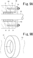
- Fig. 8 is a partial sectional perspective view of a gland packing 51 which is an embodiment of the gland packing of the invention
- Fig. 9A is a sectional view showing an example of a use state of the gland packing 51
- Fig. 9B is a schematic perspective view of the gland packing 51 of Fig. 9A
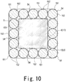
- Fig. 10 is a sectional view of the gland packing 51.
- the gland packing 51 is diagrammatically illustrated.
- the gland packing 51 is a string-like sealing material configured by using the sealing material composition 1.
- the gland packing 51 is configured so as to be able to seal a gap between an inner sealed portion (a shaft member of a predetermined apparatus) 101 and outer sealed portion (a stationary portion of the predetermined apparatus) 102 which are opposed to each other during use, in a state where the gland packing 51 is compressed in a direction (the axial direction of the shaft member) that is substantially perpendicular to the opposing direction of the portions.
- the gland packing 51 comprises an inner core member 53 configured by the sealing material composition 1.
- the gland packing 51 further comprises a plurality of yarns 54 which are disposed in the periphery of the inner core member 53 as other sealing material compositions in a state where the yarns are twisted or braided together.
- the gland packing 51 is formed into a string-like shape having a predetermined longitudinal length.
- the gland packing 51 When the gland packing 51 is to be used, as shown in Fig. 9B , for example, the packing is firstly formed or compression molded into a ring-like shape which corresponds to the inner sealed portion 101. As shown in Fig. 9A , then, the gland packing 51 is stuffed into a stuffing box 103 of the outer sealed portion 102. The stuffing box 103 is located in the periphery of the inner sealed portion 101. Thereafter, the gland packing 51 is held in a state where the packing is tightened by a gland (packing gland) 104.
- a direction intersecting with the longitudinal direction of the surrounding body 6 of the sealing material composition 1 constituting the inner core member 53 i.e., the stacking direction of the plurality of sheet-like members 10 (the stacked body 5) may be set as the vertical direction (substantially coincident with a radial direction of the inner sealed portion 101) in Fig. 10 , the lateral direction (substantially coincident with the axial direction of the inner sealed portion 101) in Fig. 10 , or a diagonal direction in Fig. 10 .
- the stacking direction is set as the lateral direction in Fig. 10 (in other words, the sheet-like members 10 are arranged in a vertical direction (a direction which is substantially perpendicular) with respect to the axial direction of the inner sealed portion 101).
- the yarns 54 are disposed in a plural number, i.e., 16 yarns.
- the yarns 54 are elongated along the inner core member 53 in the longitudinal direction of the member, and twisted or braided together so as to be bundled (disposed) around the inner core member 53, thereby forming the string-like gland packing 51 having an elongated shape.
- the yarns 54 are 16-strand hollow braided so as to cover the inner core member 53.
- the yarns 54 which constitute the gland packing 51 together with the inner core member 53 have the configuration in which the 16-strand hollow braiding using 16 yarns is employed
- the configuration of the yarns is not limited to this.
- the yarns may have a configuration in which the 4-strand square braiding using four yarns or the 8-strand square braiding using eight yarns is employed.
- the yarns 54 are formed to be thinner than the string-like inner core member 53.
- (the content rate of) the inner core member 53 in the gland packing 51 is set so as to be 5 mass% or more and 70 mass% or less based on the total mass of the gland packing 51, and therefore the yarns 54 have a content rate (mass ratio) corresponding to the content rate of the inner core member.
- the rate (the remaining percentage of the tightening force) at which the initial tightening force remains after completion of tightening is lowered (in the specification, this phenomenon is also referred to as "stress relaxation").
- the sealing property is lowered with occurrence of the stress relaxation, and therefore it is necessary that the content rate of the inner core member 53 in the gland packing 51 is 5 mass% or more.
- One of causes of the phenomenon that the initial tightening force is not maintained and the stress relaxation occurs is that the gland packing 51 itself protrudes through a gap of the apparatus, and the volume of the gland packing 51 is reduced.
- the content rate of the inner core member 53 in the gland packing 51 exceeds 70 mass%, by contrast, the rate of the yarns 54 with respect to the gland packing 51 is increased, and the amount of a lubricant becomes inadequate, whereby the sealing property is lowered. In order to prevent this from occurring, it is necessary to set the content rate of the inner core member 53 in the gland packing 51 to 70 mass% or less.
- the content rate of the inner core member 53 in the gland packing 51 is set to 5 mass% or more and 50 mass% or less based on the total mass of the gland packing 51, and, further preferably, is set to 20 mass% or more and 50 mass% or less.
- the leakage amount can be further reduced, and a remaining percentage of the tightening force which is higher than a predetermined value can be easily ensured.
- all of the yarns 54 have a substantially same structure.
- a part of the yarns 54 may have a structure which is different from that of the other yarns 54.
- each of yarns 54 is configured by an expanded graphite material 151, a lubricant, and a reinforcing material 152 for reinforcing the expanded graphite material 151.
- the expanded graphite material 151 is formed in an elongated shape.
- the lubricant is disposed so as to be generally interposed between adjacent ones of the yarns 54.
- An example of the lubricant is fluorine resin powder (PTFE dispersion or the like).
- the reinforcing material 152 is configured by using at least one wire member for reinforcing outwardly or inwardly the expanded graphite material 151.
- the reinforcing material 152 reinforces outwardly the expanded graphite material 151, and is formed to be thinner than the expanded graphite material 151.
- the at least one wire member constituting the reinforcing material 152 are a metal wire of a nickel alloy, stainless steel, or the like, and a non-metal wire configured by organic fibers (cotton or the like) or inorganic fibers (carbon fibers or the like).
- the expanded graphite material 151 is configured by a plurality of fibrous expanded graphites, and the reinforcing material 152 is a tubular member which is formed by the loop-forming knitting method using at least one wire member, and into which the expanded graphite material 151 is filled.
- the outward reinforcement structure is not limited to this.
- the outward reinforcement structure may be formed so that the expanded graphite material 151 is folded in mountain folds and valley folds, or mountain folds, or valley folds, and the reinforcing material 152 is a braided body which is configured by the above-described at least one wire member, and which covers the expanded graphite material 151 in the folded state.
- an inward reinforcement structure in which the reinforcing material 152 reinforces inwardly the expanded graphite material 151 may be employed.
- an inward reinforcement structure may be employed in which the reinforcing material 152 is disposed so to be elongated along the expanded graphite material 151, and the expanded graphite material 151 in this state is formed into a string-like body in which the expanded graphite is folded in mountain folds and valley folds, or mountain folds, or valley folds so as to envelop the reinforcing material 152.
- an inward reinforcement structure may be employed in which the reinforcing material 152 is disposed so to be elongated along the expanded graphite material 151, and the expanded graphite material 151 in this state is formed into a string-like body in which the expanded graphite material is twisted.
- the gland packing 51 in the case where, when the gland packing 51 is to be used, the gland packing is curved into a ring-like shape in order that the packing is placed between the inner sealed portion and the outer sealed portion, i.e., in order that the packing is stuffed into a stuffing box of a predetermined apparatus, the inner core member 53 (the sealing material composition 1) of the gland packing 51 enables adjacent sheet-like members 10 to be slid in the longitudinal direction of the surrounding body 6 so that the sheet-like members are positionally displaced from each other, as described above.
- the gland packing 51 when the gland packing 51 is to be used as shown in, for example, Fig. 10 , the gland packing 51 is formed into a ring-like shape so that the stacking direction of the sheet-like members 10 in the inner core member 53 coincides with the axial direction of the inner sealed portion, the stacked sheet-like members 10 can be held in a state where the sheet-like members are folded in a complex manner, and the sealing property of the inner core member 53 can be improved. Therefore, the sealing property of the gland packing 51 can be further improved.
- the inner core member 53 in which a lubricant is not used is employed, and hence the used amount of a lubricant which is a cause of the stress relaxation can be reduced in the gland packing 51. Therefore, the stress relaxation can be suppressed, and hence the lowering of the tightening force due to the gland can be suppressed. As a result, a gap is hardly formed between the gland packing 51 and the inner surface of the stuffing box, and an excellent sealing property can be ensured for a long period of time.
- the experimental apparatus 70 comprises a hydraulic unit 72 including a hydraulic cylinder 71, a first load transducer 73 for measuring the axial load, a second load transducer 74 for measuring the tightening force, a packing box 75, a heater 76, and a controller 77.
- a sealing device 80 such as shown in Fig. 9A can be incorporated in the packing box 75.
- the experimental apparatus 70 is configured so that a fluid to be sealed is introduced into a box basal portion 82 through an inlet path 81, the temperature of the introduced fluid to be sealed is raised by the heater 76, the fluid to be sealed is then supplied to the sealing device which is incorporated in the packing box 75, and the fluid that leaks from the sealing device to which the fluid to be sealed is supplied is discharged from a box main portion 83 through a discharge path 84.
- the experimental apparatus 70 further comprises: a pressure gauge 86 for detecting the pressure of the fluid to be sealed which is supplied to the sealing device; a pressure transducer 87 for transducing the detected pressure to a control signal; and a temperature sensor 88 for detecting the temperature of the fluid to be sealed.
- the experimental apparatus 70 further comprises a load cell (not shown) for measuring the remaining percentage of the tightening force, in the sealing device.
- the sealing device comprises: the stuffing box 103 of the outer sealed portion 102 (the packing box 75); gland packings (members which are placed like the gland packing 51) which are stuffed into the stuffing box 103 in a state where the packings surround the inner sealed portion (stem) 101; and the gland (packing gland) 104 for tightening the gland packings in the state where the gland packings are stuffed into the stuffing box 103.
- the sealing device is configured so that, when bolts which are disposed on the side of the gland 104 are fastened, the plurality of gland packings (of one of Examples 3 to 7, and Comparative Examples 2 and 3) that are arranged in the axial direction of the stem 101 are pressed in the axial direction of the stem 101, and a sealing portion that seals the gap between the inner surface of the stuffing box 103 and the outer surface of the stem 101 is formed.
- the gland packings of Examples 3 to 7 and Comparative Examples 2 and 3 are compress-molded into a ring-like shape corresponding to the stem 101. Then, the plurality of gland packings of one of Examples 3 to 7 and Comparative Examples 2 and 3 are disposed in the sealing device so as to surround the stem 101. Next, the sealing device comprising the gland packings is incorporated in the packing box 75.
- the temperature of the fluid to be sealed which has been introduced into the box basal portion 82 through the inlet path 81 is raised by the heater 76.
- the fluid to be sealed in which the temperature has been raised is supplied from the box basal portion 82 to the sealing device that is incorporated in the packing box 75.
- the hydraulic cylinder 71 of the hydraulic unit 72 is driven, thereby causing the stem 101 to be reciprocally slid.
- the leakage amount (the leakage amount per unit time) of the fluid from the discharge path 84 is measured, the remaining percentage of the tightening force is measured by the load cell, and the measured values are stored in the controller 77.
- the pressure and temperature of the fluid, the tightening force applied to the sealing device (gland packings), and the axial load acting on the stem 101 are measured, and the measured values are collected in the controller 77 to be stored therein.
- each of the gland packings which are compress-molded into a ring-like shape has dimensions of ⁇ 24 (inner diameter) ⁇ ⁇ 37 (outer diameter) ⁇ t6.4 (height), the liquid temperature is 400°C, and the liquid pressure is 15.5 MPa.
- the gland packing of the invention is configured by the inner core member 53 (the sealing material composition 1) and the yarns 54
- the configuration of the gland packing is not limited to this.
- the gland packing may be formed by only the sealing material composition 1 without using the yarns 54.
Description
- The present invention relates to a sealing material composition, and also to a gland packing containing the sealing material composition.
- As a sealing material composition which is used for producing a sealing material, for example, known is a yarn which is disclosed in
Patent Literature 1. A yarn of this kind is configured by a tubular member which is formed by knitting or braiding a fibrous material, and a plurality of fibrous members (fibrous expanded graphites) which are filled into the tubular member. - Each of the plurality of fibrous expanded graphites is a flexible long member. The fibrous expanded graphites are charged into the tubular member so that their longitudinal directions approximately coincide with the longitudinal direction of the tubular member, and then filled into the tubular member while being flexurally deformed, in a state where the fibrous expanded graphites are randomly arranged (see
Fig. 6 ). - In the tubular member, therefore, uneven gaps are easily formed between adjacent ones of the plurality of fibrous expanded graphites. In a usual sealing material composition, consequently, such gaps are contained in a large number. Moreover, these gaps tend to exist at relatively short intervals in the longitudinal direction of the tubular member.
- In the case where, for example, a sealing material is to be produced by using the yarn, or the yarn is to be conveyed while being wound around a round rod-like member such as a bobbin, when the yarn is flexed and curved, therefore, there is a case where the yarn is sharply bent in the curved portion, and one(s) of the plurality of fibrous expanded graphites is broken.
- In such a yarn, when a bending action is applied by an external force, namely, a predetermined amount of flexure is allowed in accordance with the external force, but, when an external force greater than a permissible amount is applied, breakage may possibly occur in the plurality of fibrous expanded graphites. Therefore, there is a possibility that breakage in the plurality of fibrous expanded graphites may cause the performance of a sealing material which is produced by using the yarn, to be lowered.
- Conventionally, a fluid apparatus such as a pump or a valve is provided with a gland packing as the above-described sealing material. A gland packing of this kind is configured by using an inner core member, and a plurality of yarns which are bundled around the inner core member in a state where the yarns are twisted or braided together (for example, see Patent Literature 2).
- When the gland packing is to be used, the gland packing is firstly adjusted so as to have a predetermined longitudinal length. While maintaining the state, then, the gland packing is formed into a ring-like shape or compress-molded into a ring-like shape according to the shaft member of a predetermined fluid apparatus. Thereafter, the gland packing is stuffed and disposed into a stuffing box which is located in the periphery of the shaft member in the fluid apparatus.
- In the gland packing, the inner core member is configured by the tubular member formed by knitting or braiding fibrous materials, and the plurality of fibrous expanded graphites filled into the tubular member. Therefore, there sometimes occurs a case where, when the gland packing is curved so as to exhibit a ring-like shape, the inner core member is sharply bent in the curved portion, and one(s) of the plurality of fibrous expanded graphites is broken.
- In the inner core member, when a bending action is applied by an external force, namely, a predetermined amount of flexure is allowed in accordance with the external force, but, when an external force greater than a permissible amount is applied, breakage may possibly occur in the plurality of fibrous expanded graphites. Therefore, there is a fear that breakage in the plurality of fibrous expanded graphites may cause the sealing property of the inner core member and hence that of the gland packing, to be lowered.
-
Patent Literature 3 discloses a yarn production process for enabling a yarn formed by filling the interior of a tubular member configured by knitting or braiding a fibrous material with expanded graphite material. The process has a fine cutting step of successively cutting an expanded graphite sheet and a supplying step of guiding and supplying a strip-like expanded graphite material produced by the fine cutting step. -
- Patent Literature 1: Japanese Patent Application Laid-Open No.
2007-138315 - Patent Literature 2: Japanese Patent Application Laid-Open No.
2007-191803 - Patent Literature 3: European Patent Application No.
1 980 658 A1 - The invention has been conducted in view of these circumstances. It is an object of the invention to provide a sealing material composition which comprises sheet-like members containing expanded graphite, and which hardly causes the sheet-like members to be broken. It is another object of the invention to provide a gland packing in which the sealing property can be improved.
- The sealing material composition of the invention is a composition wherein
the composition comprises: - a stacked body; and
- a long surrounding body which surrounds the stacked body,
- the stacked body has
- a plurality of sheet-like members each of which is formed into a tape-like shape by expanded graphite,
- the plurality of sheet-like members are stacked in a direction which intersects with a longitudinal direction of the surrounding body,
- in the plurality of sheet-like members, sheet-like members which are adjacent to each other in the stacking direction are disposed to be displaced from each other in the longitudinal direction of the surrounding body, in a relatively movable manner, and
- the surrounding body allows
- the adjacent sheet-like members to be relatively moved in the longitudinal direction of the surrounding body, while maintaining the stacked state of the adjacent sheet-like members.
- In another mode of the sealing material composition of the invention,
each of the sheet-like members has: - one longitudinal end portion; another longitudinal end portion; and a longitudinal middle portion through which the one longitudinal end portion and the other longitudinal end portion are connected to each other, and
- the one longitudinal end portion is contacted with one side of the surrounding body, and the other longitudinal end portion is contacted with another side of the surrounding body, the one side and the other side being opposite to each other across the longitudinal middle portion.
- In a further mode of the sealing material composition of the invention,
the one and other longitudinal end portions of each of the sheet-like members are elongated in a direction which is inclined with respect to the longitudinal direction of the surrounding body. - In a still further mode of the sealing material composition of the invention,
the longitudinal middle portion of each of the sheet-like members is disposed to be inclined with respect to the longitudinal direction of the surrounding body, and
at least one of the one and other longitudinal end portions of the sheet-like member is disposed along the longitudinal direction of the surrounding body. - The gland packing of the invention
contains the above-described sealing material composition. - In another mode of the gland packing of the invention,
the gland packing comprises: - an inner core member in which the sealing material composition is used; and
- yarns which are disposed in a periphery of the inner core member in a state where the yarns are twisted or braided together.
- In a further mode of the gland packing of the invention,
the surrounding body of the sealing material composition is formed by metal wires, and
each of the yarns comprises an expanded graphite material, and a reinforcing material which reinforces the expanded graphite material. - In a still further mode of the gland packing of the invention,
the inner core member is 5 mass% or more and 70 mass% or less based on a total mass of the gland packing. - In a still further mode of the gland packing of the invention,
the gland packing is formed by only the sealing material composition. - According to the invention, it is possible to provide a sealing material composition containing expanded graphite, and which hardly causes the sheet-like members to be broken. According to the invention, furthermore, it is possible to provide a gland packing in which the sealing property can be improved.
-
-
Fig. 1 is a perspective view of a sealing material composition of an embodiment of the invention. -
Fig. 2 is a schematic plan view of the sealing material composition ofFig. 1 . -
Fig. 3 is a schematic partial sectional view of the sealing material composition ofFig. 1 . -
Fig. 4 is a schematic partial sectional view of the sealing material composition ofFig. 1 in the case where the composition is flexed. -
Fig. 5 is a schematic partial sectional view of a sealing material composition of another embodiment of the invention. -
Fig. 6 is a schematic partial sectional view of a conventional sealing material composition which is a comparative example. -
Fig. 7 is a view showing experimental results. -
Fig. 8 is a partial sectional perspective view of a gland packing of a further embodiment of the invention. -
Fig. 9A is a sectional view showing an example of a use state of the gland packing ofFig. 8 , andFig. 9B is a schematic perspective view of the gland packing ofFig. 9A . -
Fig. 10 is a sectional view of the gland packing ofFig. 8 . -
Fig. 11 is a diagram schematically showing an experimental apparatus. -
Fig. 12 is a view of results of experiments using the experimental apparatus ofFig. 11 . - Firstly, an embodiment of the sealing material composition of the invention will be described with reference to the drawings.
-
Fig. 1 is a perspective view of a sealingmaterial composition 1 of an embodiment of the sealing material of the invention,Fig. 2 is a schematic plan view of the sealingmaterial composition 1, andFig. 3 is a schematic partial sectional view of the sealingmaterial composition 1. - In the sealing material composition 1 (a stacked body 5 (sheet-like members 10) and surrounding
body 6 which will be described later), it is assumed that the direction of the arrow X inFig. 1 is the longitudinal direction, that of the arrow Y is the short direction, and that of the arrow Z is the thickness direction (vertical direction). In the drawings, the dimension ratios are adequately exaggerated for the sake of convenience in description, and may be sometimes different from the actual ratios. - The sealing
material composition 1 contains expanded graphite as a material, is a member for forming a sealing material, and used for producing a sealing material such as a gland packing or a gasket. A part or whole of the sealingmaterial composition 1 can be used for forming a part (for example, an inner core member) of the sealing material or the whole (for example, a molded packing) of the sealing material. - As shown in
Figs. 1 to 3 , the sealingmaterial composition 1 comprises thestacked body 5 and the surroundingbody 6. The surroundingbody 6 is formed into a long body, and disposed so as to surround thestacked body 5. In the embodiment, the sealingmaterial composition 1 is a string-like (long) member exhibiting a rectangular parallelepiped shape, and has a longitudinal length which enables at least one sealing material such as a gland packing or a gasket to be produced. - The
stacked body 5 has a plurality of sheet-like members 10. Each of the sheet-like members 10 is formed into a tape-like (belt-like) shape by, for example, expanded graphite. The sheet-like members 10 are stacked in a direction which intersects with the longitudinal direction of the surroundingbody 6, and placed at predetermined intervals in the longitudinal direction. In the plurality of sheet-like members 10, sheet-like members 10 which are adjacent to each other in the stacking direction are disposed to be displaced from each other in the longitudinal direction of the surroundingbody 6, in a relatively movable manner. - In the embodiment, each of the sheet-
like members 10 is an expanded graphite-made tape-like member in which expanded graphite is the main component. The sheet-like member 10 is a belt-like member which has a rectangular parallelepiped shape that is substantially flat, and has an approximately constant thickness and a longitudinal length which is shorter than that of the surroundingbody 6. The sheet-like members 10 may not be strictly identical in shape with one another, and may have a production error. The sheet-like members may have any shape, as far as the shape allows thestacked body 5 to be molded. - The plurality of sheet-
like members 10 are placed so as to be elongated in a substantially same direction. The plurality of sheet-like members 10 are stacked so that thestacked body 5 has a rectangular parallelepiped shape except the both longitudinal end portions in a state where one of adjacent sheet-like members 10 is displaced by a predetermined distance from the other of the adjacent sheet-like members 10 in the longitudinal of the surroundingbody 6. - Here, the above-described direction which intersects with the longitudinal direction of the surrounding
body 6, i.e., the stacking direction of the plurality of sheet-like members 10 is a direction which is inclined with respect to the thickness direction that is perpendicular to the longitudinal and short directions of the surroundingbody 6. - In adjacent sheet-
like members 10, specifically, one sheet-like member 10 and another sheet-like member 10 are stacked so that they are relatively slidable in a direction (the longitudinal direction of the surrounding body 6) which is substantially perpendicular to the stacking direction. Irrespective of their slidings, the stacked state of the one and other sheet-like members 10 is maintained by the surroundingbody 6. - As shown particularly in
Fig. 3 , in all places where a positional displacement occurs in thestacked body 5, the displacement distances G of adjacent sheet-like members 10 (namely, the displacement distances of the one sheet-like member 10 and the other sheet-like member 10) are set so as to be substantially same as one another along the longitudinal direction of the surroundingbody 6 in the initial state shown inFig. 3 so as to avoid a state wherein external force is applied to the sealingmaterial composition 1, and the sealing material composition is flexed. - Between each pair of sheet-
like members 10 which are adjacent to each other in the stacked state, astep portion 11 is formed in accordance with the thickness of the sheet-like member 10 of one side (or the sheet-like member 10 of the other side). Thestep portions 11 are formed in both upper and lower surface portions 8, 9 of thestacked body 5, respectively, and arranged along the longitudinal direction of the surroundingbody 6 at substantially regular intervals. - The displacement distance G of adjacent sheet-
like members 10 in the initial state is not particularly limited, and may be set so that the stacked state is maintained even when the displacement distance is increased from the displacement distance G in the initial state by a relative movement (relative sliding) of the adjacent sheet-like members 10. For example, the displacement distances G may be different from one another. - In the embodiment, each of the sheet-
like members 10 has: onelongitudinal end portion 13 which is exposed in the upper surface portion 8; anotherlongitudinal end portion 14 which is exposed in the lower surface portion 9; and a longitudinalmiddle portion 15 through which the onelongitudinal end portion 13 and the otherlongitudinal end portion 14 are connected to each other. The one and otherlongitudinal end portions like member 10 are elongated in a direction which is inclined with respect to the longitudinal direction of the surroundingbody 6 so that the onelongitudinal end portion 13 is contacted with one side of the surroundingbody 6, and the otherlongitudinal end portion 14 is contacted with another side of the surroundingbody 6. The one side (the side of the upper surface portion 8 of the stacked body 5) and the other side (the side of the lower surface portion 9) are opposite to each other across the longitudinalmiddle portion 15. - As shown in
Fig. 3 , in the upper and lower surface portions 8, 9 of thestacked body 5, specifically, thestep portions 11 are formed by the one and otherlongitudinal end portions like members 10. The longitudinalmiddle portion 15 constituting the major part of each of the sheet-like members 10 has a predetermined inclination angle θ1 with respect to the longitudinal direction of the surroundingbody 6. - Each of the sheet-
like members 10 configures one layer of thestacked body 5. In the embodiment, thestacked body 5 has a structure in which seven sheet-like members 10 are stacked. The number of stacked sheet-like members 10 is not particularly limited, and may be adequately set in accordance with the thickness of each sheet-like member 10 or the like. It is requested to stack at least two sheet-like members 10. - In
Figs. 1 and3 , the gaps are exaggeratingly illustrated between adjacent sheet-like members 10. Actually, the plurality of sheet-like members 10 are stacked so as to form substantially no gaps (seeFig. 4 ), and therefore thestacked body 5 is more flattened as compared with the stacked body shownFigs. 1 and3 . - In the embodiment, at least one of the one and other
longitudinal end portions like members 10 is disposed so as to be elongated along the longitudinal direction of the surroundingbody 6. Specifically, both the one and otherlongitudinal end portions middle portion 15 so as to be elongated in substantially parallel to the longitudinal direction of the surroundingbody 6. - For example, each of the sheet-
like members 10 has a length in the longitudinal direction of about 100 mm or more and 300 mm or less (preferably, 150 mm or more and 250 mm or less), a length in the short direction (the direction which is perpendicular to both the longitudinal direction and the thickness direction Z) of about 1 mm or more and 30 mm or less (preferably, 3 mm or more and 15 mm or less), and a thickness of about 0.01 mm or more and 3.0 mm or less (preferably, 0.1 mm or more and 1.0 mm or less). - The longitudinal, short, and thickness directions of the sheet-
like members 10 are identical with those of the sealingmaterial composition 1, respectively. - As shown in the figures, the surrounding
body 6 is configured so as to allow adjacent sheet-like members 10 (the stacked body 5) to be relatively moved in the longitudinal direction of the surroundingbody 6, while maintaining the stacked state of the sheet-like members. In the embodiment, the surroundingbody 6 has a tubular shape in which thestacked body 5 can be inserted in the longitudinal direction of the surrounding body. The both longitudinal end portions of the surroundingbody 6 are configured so as to be able to have a released state where those of thestacked body 5 are exposed. - The surrounding
body 6 is a net-like member having a mesh structure, and elongated in the longitudinal direction in a state where the surroundingbody 6 is substantially in contact with the surface layers of thestacked body 5 which is surrounded by the surroundingbody 6. The surroundingbody 6 is formed so that its external shape in a state where the surroundingbody 6 surrounds thestacked body 5 substantially forms the external shape of the sealingmaterial composition 1. The surroundingbody 6 is configured by usingwire members 17 which are knitted by an adequate knitting method (for example, the loop-forming knitting method), or which are braided by an appropriate braiding method. - Although, in the embodiment, the surrounding
body 6 comprises thewire members 17 which are twisted at predetermined angle with respect to the longitudinal direction, the surrounding body is not limited to this, and may comprise wire members which are elongated in a direction that is approximately identical with the longitudinal direction. The intervals of thewire members 17 may be uneven as shown in the figures, or approximately even. - As the
wire members 17, for example, useful are: metal wires configured by a nickel alloy, or an alloy or the like in which iron is the main component, such as stainless steel; a natural resin such as natural rubber; a synthetic resin; a fluorine resin such as polytetrafluoroethylene; natural or synthetic resin fibers; and the like. In the embodiment, metal wires are used as thewire members 17. Thewire members 17 are round wires having a diameter of, for example, about 0.01 mm or more and 1 mm or less. Actually, the surroundingbody 6 surrounds thestacked body 5 which is more flattened as compared with the stacked body shown inFigs. 1 and3 so that gaps are not substantially formed between adjacent sheet-like members 10 as described above. - In this configuration, when the sealing
material composition 1 is flexed and curved in order to, for example, produce a sealing material by using the sealingmaterial composition 1, or convey the sealingmaterial composition 1 while winding the composition around a round rod member, each of adjacent sheet-like members 10 can be slid in the longitudinal direction of the surroundingbody 6 so that the sheet-like members are positionally displaced from each other. - In the sealing
material composition 1, namely, adjacent sheet-like members 10, i.e., one sheet-like member 10 and the other sheet-like member 10 can be relatively moved along the longitudinal direction of the surroundingbody 6 while the adjacent sheet-like members 10 are flexed. In this case, moreover, the stacked state of the adjacent sheet-like members 10 can be maintained. - As shown in
Fig. 4 , while maintaining the stacked state of the plurality of sheet-like members 10, specifically, the onelongitudinal end portions 13 can be slid as indicated by thearrows 18 in the upper (on the side of the outer circumferential surface) surface portion 8 of thestacked body 5, and the otherlongitudinal end portions 14 can be slid as indicated by thearrows 19 in the lower (on the side of the inner circumferential surface) surface portion 9 of thestacked body 5. - Therefore, it is possible to, when an external force is applied to the sealing
material composition 1 in order to curve it, block a portion which is sharply bent, from being formed in the sealingmaterial composition 1, and hence it is further possible to prevent one of the sheet-like members 10 from being broken because of such a bent portion. Consequently, a defect which may cause the performance to be lowered can be prevented from occurring in the sealingmaterial composition 1. - The sealing
material composition 1 of the invention is not limited to the above-described embodiment. As shown inFig. 5 , for example, sheet-like members 20 may have a longitudinal length which is shorter than that of the sheet-like members 10, and an inclination angle θ2 which is larger than the inclination angle θ1 in the embodiment. Although not illustrated, the sheet-like members 20 may have a longitudinal length which is longer than that of the sheet-like members 10, and an inclination angle which is smaller than the inclination angle θ1, with respect to the longitudinal direction of the surroundingbody 6. - An experiment on the flexibility of the the sealing material composition confirmed that the above-described effects are attained. The experiment was performed by the following method. In the experiment, as sheet-like members, Example 1 of the invention, Example 2 of the invention, and Comparative Example 1 having a structure which is similar to that of a conventional sheet-like member were prepared. Moreover, first and second round rod members were prepared.
- Example 1 has a structure similar to that of the sealing
material composition 1. The plurality of sheet-like members 10 in thestacked body 5 have a longitudinal length of about 200 mm, and constitute a structure in which seven layers of sheet-like members are stacked. The plurality of sheet-like members 10 are placed with the displacement distances G which enable the sheet-like members to form fivestep portions 11 at intervals of 10 cm in the longitudinal direction of the surroundingbody 6. - Example 2 has a structure similar to that of the sealing material composition shown in
Fig. 5 . The plurality of sheet-like members 20 in thestacked body 5 have a longitudinal length of about 100 mm, and constitute a structure in which seven layers of sheet-like members are stacked. The plurality of sheet-like members 20 are placed with the displacement distances G which enable the sheet-like members to form sevenstep portions 11 at intervals of 10 cm in the longitudinal direction of the surroundingbody 6. - Comparative Example 1 has a structure similar to that of the conventional sealing material composition shown in
Fig. 6 . A plurality offibrous members 30 are filled into a surroundingbody 32 so as to be randomly arranged. Thefibrous members 30 are placed so that a step portion is not formed in the vicinity of the surroundingbody 32, and many (a large area) gaps are produced in the surroundingbody 32. - The first round rod member is configured so that Example 1, Example 2, and Comparative Example 1 can be wound around the member over the whole circumference, and has a diameter of 10 mm. The second round rod member is configured so that Example 1, Example 2, and Comparative Example 1 can be wound around the member over the whole circumference, and has a diameter of 30 mm.
- Each of Example 1, Example 2, and Comparative Example 1 was wound around each of the first and second round rod members over a substantially whole circumference while being flexed and curved. Thereafter, each of Example 1, Example 2, and Comparative Example 1 was detached from the first and second round rod members, and the states of the sheet-
like members fibrous members 30 were checked. -
Fig. 7 shows the results of the experiment. In Example 1 and Example 2, no breakage was observed (in the figure, this is indicated by the symbol "O") in all of the sheet-like members body 32. - In the embodiment, as described above, the sheet-
like members 10 are elongated in the direction inclined with respect to the longitudinal direction of the surroundingbody 6. When a bending action is applied to the sealingmaterial composition 1, therefore, adjacent sheet-like members 10 can be smoothly slid. Consequently, it is possible to cause breakage to more hardly occur in the plurality of sheet-like members 10. - In the embodiment, the one and other
longitudinal end portions like members 10 are disposed so as to be elongated along the longitudinal direction of the surroundingbody 6. Therefore, theend portions body 6 toward the outside. Consequently, the one and otherlongitudinal end portions - Next, an embodiment of the gland packing of the invention containing the above-described
sealing material composition 1 will be described with reference to the drawings. -
Fig. 8 is a partial sectional perspective view of a gland packing 51 which is an embodiment of the gland packing of the invention,Fig. 9A is a sectional view showing an example of a use state of the gland packing 51,Fig. 9B is a schematic perspective view of the gland packing 51 ofFig. 9A , andFig. 10 is a sectional view of the gland packing 51. In these figures, for the sake of convenience of description, the gland packing 51 is diagrammatically illustrated. - As shown in
Fig. 8 , the gland packing 51 is a string-like sealing material configured by using the sealingmaterial composition 1. As shown inFig. 9A , the gland packing 51 is configured so as to be able to seal a gap between an inner sealed portion (a shaft member of a predetermined apparatus) 101 and outer sealed portion (a stationary portion of the predetermined apparatus) 102 which are opposed to each other during use, in a state where the gland packing 51 is compressed in a direction (the axial direction of the shaft member) that is substantially perpendicular to the opposing direction of the portions. - In the embodiment, as shown in
Figs. 8 and10 , the gland packing 51 comprises aninner core member 53 configured by the sealingmaterial composition 1. The gland packing 51 further comprises a plurality ofyarns 54 which are disposed in the periphery of theinner core member 53 as other sealing material compositions in a state where the yarns are twisted or braided together. The gland packing 51 is formed into a string-like shape having a predetermined longitudinal length. - When the gland packing 51 is to be used, as shown in
Fig. 9B , for example, the packing is firstly formed or compression molded into a ring-like shape which corresponds to the inner sealedportion 101. As shown inFig. 9A , then, the gland packing 51 is stuffed into astuffing box 103 of the outer sealedportion 102. Thestuffing box 103 is located in the periphery of the inner sealedportion 101. Thereafter, the gland packing 51 is held in a state where the packing is tightened by a gland (packing gland) 104. - In the case where, as shown in
Fig. 9B , the gland packing 51 is formed into a ring-like shape which corresponds to the inner sealedportion 101, a direction intersecting with the longitudinal direction of the surroundingbody 6 of the sealingmaterial composition 1 constituting theinner core member 53, i.e., the stacking direction of the plurality of sheet-like members 10 (the stacked body 5) may be set as the vertical direction (substantially coincident with a radial direction of the inner sealed portion 101) inFig. 10 , the lateral direction (substantially coincident with the axial direction of the inner sealed portion 101) inFig. 10 , or a diagonal direction inFig. 10 . Preferably, the stacking direction is set as the lateral direction inFig. 10 (in other words, the sheet-like members 10 are arranged in a vertical direction (a direction which is substantially perpendicular) with respect to the axial direction of the inner sealed portion 101). - In the embodiment, as shown in
Figs. 8 and10 , theyarns 54 are disposed in a plural number, i.e., 16 yarns. Theyarns 54 are elongated along theinner core member 53 in the longitudinal direction of the member, and twisted or braided together so as to be bundled (disposed) around theinner core member 53, thereby forming the string-like gland packing 51 having an elongated shape. - The
yarns 54 are 16-strand hollow braided so as to cover theinner core member 53. Although, in the embodiment, theyarns 54 which constitute the gland packing 51 together with theinner core member 53 have the configuration in which the 16-strand hollow braiding using 16 yarns is employed, the configuration of the yarns is not limited to this. For example, the yarns may have a configuration in which the 4-strand square braiding using four yarns or the 8-strand square braiding using eight yarns is employed. - The
yarns 54 are formed to be thinner than the string-likeinner core member 53. In the embodiment, (the content rate of) theinner core member 53 in the gland packing 51 is set so as to be 5 mass% or more and 70 mass% or less based on the total mass of the gland packing 51, and therefore theyarns 54 have a content rate (mass ratio) corresponding to the content rate of the inner core member. - Although the detail will be described later with reference to
Fig. 12 , when the content rate of theinner core member 53 in the gland packing 51 is less than 5 mass%, the rate (the remaining percentage of the tightening force) at which the initial tightening force remains after completion of tightening is lowered (in the specification, this phenomenon is also referred to as "stress relaxation"). The sealing property is lowered with occurrence of the stress relaxation, and therefore it is necessary that the content rate of theinner core member 53 in the gland packing 51 is 5 mass% or more. One of causes of the phenomenon that the initial tightening force is not maintained and the stress relaxation occurs is that the gland packing 51 itself protrudes through a gap of the apparatus, and the volume of the gland packing 51 is reduced. When the content rate of theinner core member 53 in the gland packing 51 exceeds 70 mass%, by contrast, the rate of theyarns 54 with respect to the gland packing 51 is increased, and the amount of a lubricant becomes inadequate, whereby the sealing property is lowered. In order to prevent this from occurring, it is necessary to set the content rate of theinner core member 53 in the gland packing 51 to 70 mass% or less. - More preferably, the content rate of the
inner core member 53 in the gland packing 51 is set to 5 mass% or more and 50 mass% or less based on the total mass of the gland packing 51, and, further preferably, is set to 20 mass% or more and 50 mass% or less. When the content rate of theinner core member 53 in the gland packing 51 is set to 20 mass% or more and 50 mass% or less, the leakage amount can be further reduced, and a remaining percentage of the tightening force which is higher than a predetermined value can be easily ensured. - In the above, it is assumed that all of the
yarns 54 have a substantially same structure. Alternatively, for example, a part of theyarns 54 may have a structure which is different from that of theother yarns 54. - In the embodiment, as shown in
Fig. 10 , each ofyarns 54 is configured by an expandedgraphite material 151, a lubricant, and a reinforcingmaterial 152 for reinforcing the expandedgraphite material 151. The expandedgraphite material 151 is formed in an elongated shape. The lubricant is disposed so as to be generally interposed between adjacent ones of theyarns 54. An example of the lubricant is fluorine resin powder (PTFE dispersion or the like). - The reinforcing
material 152 is configured by using at least one wire member for reinforcing outwardly or inwardly the expandedgraphite material 151. In the embodiment, the reinforcingmaterial 152 reinforces outwardly the expandedgraphite material 151, and is formed to be thinner than the expandedgraphite material 151. Examples of the at least one wire member constituting the reinforcingmaterial 152 are a metal wire of a nickel alloy, stainless steel, or the like, and a non-metal wire configured by organic fibers (cotton or the like) or inorganic fibers (carbon fibers or the like). - In the case where an outward reinforcement structure in which the reinforcing
material 152 reinforces outwardly the expandedgraphite material 151 is employed as in the embodiment, the expandedgraphite material 151 is configured by a plurality of fibrous expanded graphites, and the reinforcingmaterial 152 is a tubular member which is formed by the loop-forming knitting method using at least one wire member, and into which the expandedgraphite material 151 is filled. The outward reinforcement structure is not limited to this. For example, the outward reinforcement structure may be formed so that the expandedgraphite material 151 is folded in mountain folds and valley folds, or mountain folds, or valley folds, and the reinforcingmaterial 152 is a braided body which is configured by the above-described at least one wire member, and which covers the expandedgraphite material 151 in the folded state. - In place of the outward reinforcement structure, an inward reinforcement structure in which the reinforcing
material 152 reinforces inwardly the expandedgraphite material 151 may be employed. In this case, for example, an inward reinforcement structure may be employed in which the reinforcingmaterial 152 is disposed so to be elongated along the expandedgraphite material 151, and the expandedgraphite material 151 in this state is formed into a string-like body in which the expanded graphite is folded in mountain folds and valley folds, or mountain folds, or valley folds so as to envelop the reinforcingmaterial 152. Alternatively, an inward reinforcement structure may be employed in which the reinforcingmaterial 152 is disposed so to be elongated along the expandedgraphite material 151, and the expandedgraphite material 151 in this state is formed into a string-like body in which the expanded graphite material is twisted. - According to the configuration, in the case where, when the gland packing 51 is to be used, the gland packing is curved into a ring-like shape in order that the packing is placed between the inner sealed portion and the outer sealed portion, i.e., in order that the packing is stuffed into a stuffing box of a predetermined apparatus, the inner core member 53 (the sealing material composition 1) of the gland packing 51 enables adjacent sheet-
like members 10 to be slid in the longitudinal direction of the surroundingbody 6 so that the sheet-like members are positionally displaced from each other, as described above. - While preventing the expanded graphite of the sheet-
like members 10 from being partly broken, therefore, it is possible to improve the flexibility of theinner core member 53, i.e., that of the gland packing 51 using the inner core member. When the gland packing 51 is curved, consequently, the lowering of the sealing property of theinner core member 53 which is due to partial breakage of the expanded graphite of the sheet-like members 10 can be suppressed from occurring. Therefore, the sealing property of the gland packing 51 can be improved. - In the case where, when the gland packing 51 is to be used as shown in, for example,
Fig. 10 , the gland packing 51 is formed into a ring-like shape so that the stacking direction of the sheet-like members 10 in theinner core member 53 coincides with the axial direction of the inner sealed portion, the stacked sheet-like members 10 can be held in a state where the sheet-like members are folded in a complex manner, and the sealing property of theinner core member 53 can be improved. Therefore, the sealing property of the gland packing 51 can be further improved. - In the embodiment, the
inner core member 53 in which a lubricant is not used is employed, and hence the used amount of a lubricant which is a cause of the stress relaxation can be reduced in the gland packing 51. Therefore, the stress relaxation can be suppressed, and hence the lowering of the tightening force due to the gland can be suppressed. As a result, a gap is hardly formed between the gland packing 51 and the inner surface of the stuffing box, and an excellent sealing property can be ensured for a long period of time. - When the following experiment was performed, it was confirmed that the use of the gland packing of the invention can suppress reduction of the leakage amount of the fluid per unit time (the sealing property), and the lowering of the remaining percentage of the tightening force (the stress relaxation). In the experiment, Examples 3 to 7 of the invention were prepared, and Comparative Examples 2 and 3 were prepared. Moreover, an
experimental apparatus 70 corresponding to the examples and the comparative examples was prepared. - Example 3 is a gland packing which comprises: an inner core member having a mass ratio of the stacked body (expanded graphite) : the surrounding body (metal wires) = 85:15; and a plurality of yarns having a mass ratio of the expanded graphite material : the reinforcing material (metal wire) : the lubricant = 80:10:10, and which has a mass ratio of the inner core member : the plurality of yarns = 5:95.
- Example 4 is a gland packing which comprises: an inner core member having a mass ratio of the stacked body (expanded graphite) : the surrounding body (metal wires) = 85:15; and a plurality of yarns having a mass ratio of the expanded graphite material : the reinforcing material (metal wire) : the lubricant = 80:10:10, and which has a mass ratio of the inner core member : the plurality of yarns = 20:80.
- Example 5 is a gland packing which comprises: an inner core member having a mass ratio of the stacked body (expanded graphite) : the surrounding body (metal wires) = 85:15; and a plurality of yarns having a mass ratio of the expanded graphite material : the reinforcing material (metal wire) : the lubricant = 80:10:10, and which has a mass ratio of the inner core member : the plurality of yarns = 30:70.
- Example 6 is a gland packing which comprises: an inner core member having a mass ratio of the stacked body (expanded graphite) : the surrounding body (metal wires) = 85:15; and a plurality of yarns having a mass ratio of the expanded graphite material : the reinforcing material (metal wire) : the lubricant = 80:10:10, and which has a mass ratio of the inner core member : the plurality of yarns = 50:50.
- Example 7 is a gland packing which comprises: an inner core member having a mass ratio of the stacked body (expanded graphite) : the surrounding body (metal wires) = 85:15; and a plurality of yarns having a mass ratio of the expanded graphite material : the reinforcing material (metal wire) : the lubricant = 80:10:10, and which has a mass ratio of the inner core member : the plurality of yarns = 70:30.
- Comparative Example 2 is a gland packing which comprises: an inner core member having a mass ratio of the stacked body (expanded graphite) : the surrounding body (metal wires) = 85:15; and a plurality of yarns having a mass ratio of the expanded graphite material : the reinforcing material (metal wire) : the lubricant = 80:10:10, and which has a mass ratio of the inner core member : the plurality of yarns = 4:96.
- Comparative Example 3 is a gland packing which comprises: an inner core member having a mass ratio of the stacked body (expanded graphite) : the surrounding body (metal wires) = 85:15; and a plurality of yarns having a mass ratio of the expanded graphite material : the reinforcing material (metal wire) : the lubricant = 80:10:10, and which has a mass ratio of the inner core member : the plurality of yarns = 71:29.
- As shown in
Fig. 11 , theexperimental apparatus 70 comprises ahydraulic unit 72 including ahydraulic cylinder 71, a first load transducer 73 for measuring the axial load, asecond load transducer 74 for measuring the tightening force, apacking box 75, aheater 76, and acontroller 77. A sealingdevice 80 such as shown inFig. 9A can be incorporated in thepacking box 75. - The
experimental apparatus 70 is configured so that a fluid to be sealed is introduced into a boxbasal portion 82 through aninlet path 81, the temperature of the introduced fluid to be sealed is raised by theheater 76, the fluid to be sealed is then supplied to the sealing device which is incorporated in thepacking box 75, and the fluid that leaks from the sealing device to which the fluid to be sealed is supplied is discharged from a boxmain portion 83 through adischarge path 84. - The
experimental apparatus 70 further comprises: apressure gauge 86 for detecting the pressure of the fluid to be sealed which is supplied to the sealing device; apressure transducer 87 for transducing the detected pressure to a control signal; and a temperature sensor 88 for detecting the temperature of the fluid to be sealed. Theexperimental apparatus 70 further comprises a load cell (not shown) for measuring the remaining percentage of the tightening force, in the sealing device. - Referring to
Fig. 9A , the sealing device comprises: thestuffing box 103 of the outer sealed portion 102 (the packing box 75); gland packings (members which are placed like the gland packing 51) which are stuffed into thestuffing box 103 in a state where the packings surround the inner sealed portion (stem) 101; and the gland (packing gland) 104 for tightening the gland packings in the state where the gland packings are stuffed into thestuffing box 103. - The sealing device is configured so that, when bolts which are disposed on the side of the
gland 104 are fastened, the plurality of gland packings (of one of Examples 3 to 7, and Comparative Examples 2 and 3) that are arranged in the axial direction of thestem 101 are pressed in the axial direction of thestem 101, and a sealing portion that seals the gap between the inner surface of thestuffing box 103 and the outer surface of thestem 101 is formed. - In the experiment, firstly, the gland packings of Examples 3 to 7 and Comparative Examples 2 and 3 are compress-molded into a ring-like shape corresponding to the
stem 101. Then, the plurality of gland packings of one of Examples 3 to 7 and Comparative Examples 2 and 3 are disposed in the sealing device so as to surround thestem 101. Next, the sealing device comprising the gland packings is incorporated in thepacking box 75. - Then, the temperature of the fluid to be sealed which has been introduced into the box
basal portion 82 through theinlet path 81 is raised by theheater 76. Next, the fluid to be sealed in which the temperature has been raised is supplied from the boxbasal portion 82 to the sealing device that is incorporated in thepacking box 75. When the supply of the fluid to be sealed is to be supplied, thehydraulic cylinder 71 of thehydraulic unit 72 is driven, thereby causing thestem 101 to be reciprocally slid. - In the
experimental apparatus 70, during the above, the leakage amount (the leakage amount per unit time) of the fluid from thedischarge path 84 is measured, the remaining percentage of the tightening force is measured by the load cell, and the measured values are stored in thecontroller 77. The pressure and temperature of the fluid, the tightening force applied to the sealing device (gland packings), and the axial load acting on thestem 101 are measured, and the measured values are collected in thecontroller 77 to be stored therein. - The conditions of the experiment using the
experimental apparatus 70 are as follows. In Examples 3 to 7 and Comparative Examples 2 and 3, each of the gland packings which are compress-molded into a ring-like shape has dimensions of ϕ24 (inner diameter) × ϕ37 (outer diameter) × t6.4 (height), the liquid temperature is 400°C, and the liquid pressure is 15.5 MPa. - According to the experiment, the experimental results shown in
Fig. 12 were obtained. From the experimental results shown inFig. 12 , it was revealed that, in each of Examples 3 to 7, the leakage amount (the leakage amount per unit time) from thedischarge path 84, and the lowering of the remaining percentage of the tightening force (stress relaxation) can be suppressed, and are within predetermined reference values (in the figure, this is indicated by the symbol "○"). Namely, it became apparent that the examples have an effect that the leakage amount (sealing property) of the fluid per unit time, and the lowering of the remaining percentage of the tightening force can be suppressed, i.e., an effect that the sealing property can be improved. - From the experimental results shown in
Fig. 12 , it was revealed that, in Comparative Example 2, it is difficult to suppress the lowering of the remaining percentage of the tightening force, and the remaining percentage is deviated from the predetermined reference values (in the figure, this is indicated by the symbol "×"). Moreover, it was revealed that, in Comparative Example 3, it is difficult to suppress the leakage amount (the leakage amount per unit time) from thedischarge path 84, and the leakage amount is largely deviated from the predetermined reference values (in the figure, this is indicated by the symbol "×"). Namely, it became apparent that, in a configuration such as that of Comparative Example 2 or 3, the improvement of the sealing property cannot be expected. - Although, in the embodiment, the gland packing of the invention is configured by the inner core member 53 (the sealing material composition 1) and the
yarns 54, the configuration of the gland packing is not limited to this. The gland packing may be formed by only the sealingmaterial composition 1 without using theyarns 54. - Obviously, numerous modifications and variations of the present invention are possible in light of the above teachings. It is therefore to be understood that within the scope of the appended claims, the invention may be practiced otherwise than as specifically described herein.
-
- 1
- sealing material composition
- 5
- stacked body
- 6
- surrounding body
- 10
- sheet-like member
- 13
- one longitudinal end portion of sheet-like member
- 14
- other longitudinal end portion of sheet-like member
- 15
- longitudinal middle portion of sheet-like member
- 51
- gland packing
- 53
- inner core member
- 54
- yarn
- 151
- expanded graphite material
- 152
- reinforcing material
Claims (16)
- A sealing material composition which is a composition of a sealing material, characterized in that
the composition comprises:a stacked body; anda long surrounding body which surrounds the stacked body,the stacked body hasa plurality of sheet-like members each of which is formed into a tape-like shape by expanded graphite, characterised in that said plurality of sheet-like members are stacked in a direction which intersects with a longitudinal direction of the surrounding body,in the plurality of sheet-like members, sheet-like members which are adjacent to each other in the stacking direction are disposed, in use, to be displaced from each other in the longitudinal direction of the surrounding body, in a relatively movable manner, andthe surrounding body allows the adjacent sheet-like members to be relatively moved in the longitudinal direction of the surrounding body, while maintaining the stacked state of the adjacent sheet-like members. - The sealing material composition according to claim 1, wherein
the sheet-like members are placed at predetermined intervals along the longitudinal direction of the surrounding body. - The sealing material composition according to claim 1, wherein
each of the sheet-like members has:one longitudinal end portion; another longitudinal end portion; and a longitudinal middle portion through which the one longitudinal end portion and the other longitudinal end portion are connected to each other, andthe one longitudinal end portion is contacted with one side of the surrounding body, and the other longitudinal end portion is contacted with another side of the surrounding body, the one side and the other side being opposite to each other across the longitudinal middle portion. - The sealing material composition according to claim 2, wherein
each of the sheet-like members has:one longitudinal end portion; another longitudinal end portion; and a longitudinal middle portion through which the one longitudinal end portion and the other longitudinal end portion are connected to each other, andthe one longitudinal end portion is contacted with one side of the surrounding body, and the other longitudinal end portion is contacted with another side of the surrounding body, the one side and the other side being opposite to each other across the longitudinal middle portion. - The sealing material composition according to claim 3, wherein the one and other longitudinal end portions of each of the sheet-like members are elongated in a direction which is inclined with respect to the longitudinal direction of the surrounding body.
- The sealing material composition according to claim 4, wherein the one and other longitudinal end portions of each of the sheet-like members are elongated in a direction which is inclined with respect to the longitudinal direction of the surrounding body.
- The sealing material composition according to claim 3, wherein
the longitudinal middle portion of each of the sheet-like members is disposed to be inclined with respect to the longitudinal direction of the surrounding body, and
at least one of the one and other longitudinal end portions of the sheet-like member is disposed along the longitudinal direction of the surrounding body. - The sealing material composition according to claim 4, wherein
the longitudinal middle portion of each of the sheet-like members is disposed to be inclined with respect to the longitudinal direction of the surrounding body, and
at least one of the one and other longitudinal end portions of the sheet-like member is disposed along the longitudinal direction of the surrounding body. - The sealing material composition according to claim 5, wherein
the longitudinal middle portion of each of the sheet-like members is disposed to be inclined with respect to the longitudinal direction of the surrounding body, and
at least one of the one and other longitudinal end portions of the sheet-like member is disposed along the longitudinal direction of the surrounding body. - The sealing material composition according to claim 6, wherein
the longitudinal middle portion of each of the sheet-like members is disposed to be inclined with respect to the longitudinal direction of the surrounding body, and
at least one of the one and other longitudinal end portions of the sheet-like member is disposed along the longitudinal direction of the surrounding body. - A gland packing characterized in that the gland packing contains the sealing material composition according to claim 1.
- The gland packing according to claim 11, wherein
the gland packing comprises:an inner core member in which the sealing material composition is used; andyarns which are disposed in a periphery of the inner core member in a state where the yarns are twisted or braided together. - The gland packing according to claim 12, wherein
the surrounding body of the sealing material composition is formed by metal wires, and
each of the yarns comprises an expanded graphite material, and a reinforcing material which reinforces the expanded graphite material. - The gland packing according to claim 12, characterized in that the inner core member is 5 mass% or more and 70 mass% or less based on a total mass of the gland packing.
- The gland packing according to claim 13, characterized in that the inner core member is 5 mass% or more and 70 mass% or less based on a total mass of the gland packing.
- The gland packing according to claim 11, characterized in that the gland packing is formed by only the sealing material composition.
Applications Claiming Priority (2)
| Application Number | Priority Date | Filing Date | Title |
|---|---|---|---|
| JP2016212846A JP6749214B2 (en) | 2016-10-31 | 2016-10-31 | Sealing material composition |
| JP2016212847A JP6749215B2 (en) | 2016-10-31 | 2016-10-31 | Gland packing |
Publications (2)
| Publication Number | Publication Date |
|---|---|
| EP3315828A1 EP3315828A1 (en) | 2018-05-02 |
| EP3315828B1 true EP3315828B1 (en) | 2019-10-16 |
Family
ID=60201342
Family Applications (1)
| Application Number | Title | Priority Date | Filing Date |
|---|---|---|---|
| EP17198588.0A Active EP3315828B1 (en) | 2016-10-31 | 2017-10-26 | Sealing material composition and gland packing containing the sealing material composition |
Country Status (3)
| Country | Link |
|---|---|
| US (1) | US10533268B2 (en) |
| EP (1) | EP3315828B1 (en) |
| CN (1) | CN108019517B (en) |
Family Cites Families (13)
| Publication number | Priority date | Publication date | Assignee | Title |
|---|---|---|---|---|
| JPS631863A (en) * | 1986-06-18 | 1988-01-06 | Nippon Pillar Packing Co Ltd | Gland packing |
| US5240769A (en) * | 1986-11-25 | 1993-08-31 | Nippon Pillar Packing Co. Ltd. | Packing material and packing made of the same |
| JPS63135653A (en) * | 1986-11-25 | 1988-06-08 | Nippon Pillar Packing Co Ltd | Packing material |
| CN1019681B (en) * | 1991-03-12 | 1992-12-30 | 山东滨州柔性石墨密封件厂 | Expanded graphite and carbon fiber bar braided composite packing material |
| JP4252669B2 (en) * | 1999-05-14 | 2009-04-08 | ジャパンマテックス株式会社 | Material used for expanded graphite gland packing, expanded graphite gland packing made of this material, and method for producing the expanded graphite gland packing |
| JP4164210B2 (en) * | 1999-11-08 | 2008-10-15 | 日本ピラー工業株式会社 | Expanded graphite knitting yarn and gland packing |
| TW200535356A (en) * | 2004-03-31 | 2005-11-01 | Nippon Pillar Packing | Expanding graphite yarn, and gland packing |
| JP4340647B2 (en) | 2005-11-16 | 2009-10-07 | 日本ピラー工業株式会社 | Yarn and gland packing |
| JP4378351B2 (en) | 2006-01-17 | 2009-12-02 | 日本ピラー工業株式会社 | Yarn manufacturing method |
| EP1980658B1 (en) * | 2006-01-17 | 2016-04-13 | Nippon Pillar Packing Co., Ltd. | Process and apparatus for producing yarn and gland packing |
| JP4857151B2 (en) * | 2007-03-08 | 2012-01-18 | 日本ピラー工業株式会社 | Gland packing |
| JP5853086B1 (en) * | 2014-11-18 | 2016-02-09 | 日本ピラー工業株式会社 | Yarn manufacturing method |
| US10100444B2 (en) * | 2014-11-18 | 2018-10-16 | Nippon Pillar Packing Co., Ltd. | Yarn and gland packing |
-
2017
- 2017-10-17 CN CN201710961426.7A patent/CN108019517B/en active Active
- 2017-10-25 US US15/793,094 patent/US10533268B2/en active Active
- 2017-10-26 EP EP17198588.0A patent/EP3315828B1/en active Active
Non-Patent Citations (1)
| Title |
|---|
| None * |
Also Published As
| Publication number | Publication date |
|---|---|
| EP3315828A1 (en) | 2018-05-02 |
| US10533268B2 (en) | 2020-01-14 |
| CN108019517B (en) | 2020-12-01 |
| CN108019517A (en) | 2018-05-11 |
| US20180119316A1 (en) | 2018-05-03 |
Similar Documents
| Publication | Publication Date | Title |
|---|---|---|
| EP0340303B1 (en) | Packing material and packing made of the same | |
| EP1582785B1 (en) | Braiding yarn made of expanded graphite, and gland packing | |
| EP0794367A2 (en) | Seal Material | |
| US5499827A (en) | Seal for shafts and valve stems | |
| TW457345B (en) | Expanded graphite-made knitting yarn | |
| CN101300381B (en) | Yarn and gland packing | |
| US20130307229A1 (en) | Compressible packing | |
| EP3315828B1 (en) | Sealing material composition and gland packing containing the sealing material composition | |
| EP1098116A3 (en) | Expanded graphite knitting yarn and a gland packing | |
| US9239115B2 (en) | Gland packing and packing set | |
| JP6749215B2 (en) | Gland packing | |
| EP3222777B1 (en) | Method for producing yarn | |
| EP3222774B1 (en) | Yarn and gland packing | |
| EP1179697B1 (en) | Expanded graphite-made knitting yarn | |
| JPH078928Y2 (en) | Puckkin | |
| JP2005282772A (en) | Gland packing | |
| JP2836615B2 (en) | Gland packing | |
| JP3927963B2 (en) | Expanded graphite knitting yarn and gland packing | |
| JPH046234B2 (en) | ||
| JP2002022023A (en) | Yarn for gland packing and gland packing using the same | |
| JP2000170920A (en) | Gland packing and manufacture thereof | |
| BG4497U1 (en) | Diagonally braided packing | |
| JP2005291264A (en) | Expanding graphite yarn and gland packing | |
| JP2021011667A (en) | Yarn, gland packing, and method for producing yarn | |
| JP2001330154A (en) | Ring packing made of expansion graphite and its manufacturing method |
Legal Events
| Date | Code | Title | Description |
|---|---|---|---|
| PUAI | Public reference made under article 153(3) epc to a published international application that has entered the european phase |
Free format text: ORIGINAL CODE: 0009012 |
|
| STAA | Information on the status of an ep patent application or granted ep patent |
Free format text: STATUS: THE APPLICATION HAS BEEN PUBLISHED |
|
| AK | Designated contracting states |
Kind code of ref document: A1 Designated state(s): AL AT BE BG CH CY CZ DE DK EE ES FI FR GB GR HR HU IE IS IT LI LT LU LV MC MK MT NL NO PL PT RO RS SE SI SK SM TR |
|
| AX | Request for extension of the european patent |
Extension state: BA ME |
|
| STAA | Information on the status of an ep patent application or granted ep patent |
Free format text: STATUS: REQUEST FOR EXAMINATION WAS MADE |
|
| 17P | Request for examination filed |
Effective date: 20180910 |
|
| RBV | Designated contracting states (corrected) |
Designated state(s): AL AT BE BG CH CY CZ DE DK EE ES FI FR GB GR HR HU IE IS IT LI LT LU LV MC MK MT NL NO PL PT RO RS SE SI SK SM TR |
|
| GRAP | Despatch of communication of intention to grant a patent |
Free format text: ORIGINAL CODE: EPIDOSNIGR1 |
|
| STAA | Information on the status of an ep patent application or granted ep patent |
Free format text: STATUS: GRANT OF PATENT IS INTENDED |
|
| INTG | Intention to grant announced |
Effective date: 20190506 |
|
| GRAS | Grant fee paid |
Free format text: ORIGINAL CODE: EPIDOSNIGR3 |
|
| GRAA | (expected) grant |
Free format text: ORIGINAL CODE: 0009210 |
|
| STAA | Information on the status of an ep patent application or granted ep patent |
Free format text: STATUS: THE PATENT HAS BEEN GRANTED |
|
| AK | Designated contracting states |
Kind code of ref document: B1 Designated state(s): AL AT BE BG CH CY CZ DE DK EE ES FI FR GB GR HR HU IE IS IT LI LT LU LV MC MK MT NL NO PL PT RO RS SE SI SK SM TR |
|
| REG | Reference to a national code |
Ref country code: GB Ref legal event code: FG4D |
|
| REG | Reference to a national code |
Ref country code: CH Ref legal event code: EP |
|
| REG | Reference to a national code |
Ref country code: DE Ref legal event code: R096 Ref document number: 602017007829 Country of ref document: DE |
|
| REG | Reference to a national code |
Ref country code: IE Ref legal event code: FG4D |
|
| REG | Reference to a national code |
Ref country code: AT Ref legal event code: REF Ref document number: 1191600 Country of ref document: AT Kind code of ref document: T Effective date: 20191115 |
|
| REG | Reference to a national code |
Ref country code: NL Ref legal event code: MP Effective date: 20191016 |
|
| REG | Reference to a national code |
Ref country code: LT Ref legal event code: MG4D |
|
| REG | Reference to a national code |
Ref country code: AT Ref legal event code: MK05 Ref document number: 1191600 Country of ref document: AT Kind code of ref document: T Effective date: 20191016 |
|
| PG25 | Lapsed in a contracting state [announced via postgrant information from national office to epo] |
Ref country code: NL Free format text: LAPSE BECAUSE OF FAILURE TO SUBMIT A TRANSLATION OF THE DESCRIPTION OR TO PAY THE FEE WITHIN THE PRESCRIBED TIME-LIMIT Effective date: 20191016 Ref country code: AT Free format text: LAPSE BECAUSE OF FAILURE TO SUBMIT A TRANSLATION OF THE DESCRIPTION OR TO PAY THE FEE WITHIN THE PRESCRIBED TIME-LIMIT Effective date: 20191016 Ref country code: FI Free format text: LAPSE BECAUSE OF FAILURE TO SUBMIT A TRANSLATION OF THE DESCRIPTION OR TO PAY THE FEE WITHIN THE PRESCRIBED TIME-LIMIT Effective date: 20191016 Ref country code: BG Free format text: LAPSE BECAUSE OF FAILURE TO SUBMIT A TRANSLATION OF THE DESCRIPTION OR TO PAY THE FEE WITHIN THE PRESCRIBED TIME-LIMIT Effective date: 20200116 Ref country code: GR Free format text: LAPSE BECAUSE OF FAILURE TO SUBMIT A TRANSLATION OF THE DESCRIPTION OR TO PAY THE FEE WITHIN THE PRESCRIBED TIME-LIMIT Effective date: 20200117 Ref country code: LT Free format text: LAPSE BECAUSE OF FAILURE TO SUBMIT A TRANSLATION OF THE DESCRIPTION OR TO PAY THE FEE WITHIN THE PRESCRIBED TIME-LIMIT Effective date: 20191016 Ref country code: PT Free format text: LAPSE BECAUSE OF FAILURE TO SUBMIT A TRANSLATION OF THE DESCRIPTION OR TO PAY THE FEE WITHIN THE PRESCRIBED TIME-LIMIT Effective date: 20200217 Ref country code: PL Free format text: LAPSE BECAUSE OF FAILURE TO SUBMIT A TRANSLATION OF THE DESCRIPTION OR TO PAY THE FEE WITHIN THE PRESCRIBED TIME-LIMIT Effective date: 20191016 Ref country code: SE Free format text: LAPSE BECAUSE OF FAILURE TO SUBMIT A TRANSLATION OF THE DESCRIPTION OR TO PAY THE FEE WITHIN THE PRESCRIBED TIME-LIMIT Effective date: 20191016 Ref country code: NO Free format text: LAPSE BECAUSE OF FAILURE TO SUBMIT A TRANSLATION OF THE DESCRIPTION OR TO PAY THE FEE WITHIN THE PRESCRIBED TIME-LIMIT Effective date: 20200116 Ref country code: LV Free format text: LAPSE BECAUSE OF FAILURE TO SUBMIT A TRANSLATION OF THE DESCRIPTION OR TO PAY THE FEE WITHIN THE PRESCRIBED TIME-LIMIT Effective date: 20191016 |
|
| PG25 | Lapsed in a contracting state [announced via postgrant information from national office to epo] |
Ref country code: RS Free format text: LAPSE BECAUSE OF FAILURE TO SUBMIT A TRANSLATION OF THE DESCRIPTION OR TO PAY THE FEE WITHIN THE PRESCRIBED TIME-LIMIT Effective date: 20191016 Ref country code: HR Free format text: LAPSE BECAUSE OF FAILURE TO SUBMIT A TRANSLATION OF THE DESCRIPTION OR TO PAY THE FEE WITHIN THE PRESCRIBED TIME-LIMIT Effective date: 20191016 Ref country code: IS Free format text: LAPSE BECAUSE OF FAILURE TO SUBMIT A TRANSLATION OF THE DESCRIPTION OR TO PAY THE FEE WITHIN THE PRESCRIBED TIME-LIMIT Effective date: 20200224 |
|
| PG25 | Lapsed in a contracting state [announced via postgrant information from national office to epo] |
Ref country code: AL Free format text: LAPSE BECAUSE OF FAILURE TO SUBMIT A TRANSLATION OF THE DESCRIPTION OR TO PAY THE FEE WITHIN THE PRESCRIBED TIME-LIMIT Effective date: 20191016 |
|
| REG | Reference to a national code |
Ref country code: DE Ref legal event code: R097 Ref document number: 602017007829 Country of ref document: DE |
|
| PG2D | Information on lapse in contracting state deleted |
Ref country code: IS |
|
| PG25 | Lapsed in a contracting state [announced via postgrant information from national office to epo] |
Ref country code: CZ Free format text: LAPSE BECAUSE OF FAILURE TO SUBMIT A TRANSLATION OF THE DESCRIPTION OR TO PAY THE FEE WITHIN THE PRESCRIBED TIME-LIMIT Effective date: 20191016 Ref country code: RO Free format text: LAPSE BECAUSE OF FAILURE TO SUBMIT A TRANSLATION OF THE DESCRIPTION OR TO PAY THE FEE WITHIN THE PRESCRIBED TIME-LIMIT Effective date: 20191016 Ref country code: LU Free format text: LAPSE BECAUSE OF NON-PAYMENT OF DUE FEES Effective date: 20191026 Ref country code: ES Free format text: LAPSE BECAUSE OF FAILURE TO SUBMIT A TRANSLATION OF THE DESCRIPTION OR TO PAY THE FEE WITHIN THE PRESCRIBED TIME-LIMIT Effective date: 20191016 Ref country code: MC Free format text: LAPSE BECAUSE OF FAILURE TO SUBMIT A TRANSLATION OF THE DESCRIPTION OR TO PAY THE FEE WITHIN THE PRESCRIBED TIME-LIMIT Effective date: 20191016 Ref country code: EE Free format text: LAPSE BECAUSE OF FAILURE TO SUBMIT A TRANSLATION OF THE DESCRIPTION OR TO PAY THE FEE WITHIN THE PRESCRIBED TIME-LIMIT Effective date: 20191016 Ref country code: DK Free format text: LAPSE BECAUSE OF FAILURE TO SUBMIT A TRANSLATION OF THE DESCRIPTION OR TO PAY THE FEE WITHIN THE PRESCRIBED TIME-LIMIT Effective date: 20191016 Ref country code: IS Free format text: LAPSE BECAUSE OF FAILURE TO SUBMIT A TRANSLATION OF THE DESCRIPTION OR TO PAY THE FEE WITHIN THE PRESCRIBED TIME-LIMIT Effective date: 20200216 |
|
| REG | Reference to a national code |
Ref country code: BE Ref legal event code: MM Effective date: 20191031 |
|
| PLBE | No opposition filed within time limit |
Free format text: ORIGINAL CODE: 0009261 |
|
| STAA | Information on the status of an ep patent application or granted ep patent |
Free format text: STATUS: NO OPPOSITION FILED WITHIN TIME LIMIT |
|
| PG25 | Lapsed in a contracting state [announced via postgrant information from national office to epo] |
Ref country code: SK Free format text: LAPSE BECAUSE OF FAILURE TO SUBMIT A TRANSLATION OF THE DESCRIPTION OR TO PAY THE FEE WITHIN THE PRESCRIBED TIME-LIMIT Effective date: 20191016 Ref country code: BE Free format text: LAPSE BECAUSE OF NON-PAYMENT OF DUE FEES Effective date: 20191031 Ref country code: SM Free format text: LAPSE BECAUSE OF FAILURE TO SUBMIT A TRANSLATION OF THE DESCRIPTION OR TO PAY THE FEE WITHIN THE PRESCRIBED TIME-LIMIT Effective date: 20191016 |
|
| 26N | No opposition filed |
Effective date: 20200717 |
|
| PG25 | Lapsed in a contracting state [announced via postgrant information from national office to epo] |
Ref country code: IE Free format text: LAPSE BECAUSE OF NON-PAYMENT OF DUE FEES Effective date: 20191026 Ref country code: FR Free format text: LAPSE BECAUSE OF NON-PAYMENT OF DUE FEES Effective date: 20191216 |
|
| PG25 | Lapsed in a contracting state [announced via postgrant information from national office to epo] |
Ref country code: SI Free format text: LAPSE BECAUSE OF FAILURE TO SUBMIT A TRANSLATION OF THE DESCRIPTION OR TO PAY THE FEE WITHIN THE PRESCRIBED TIME-LIMIT Effective date: 20191016 |
|
| PG25 | Lapsed in a contracting state [announced via postgrant information from national office to epo] |
Ref country code: CY Free format text: LAPSE BECAUSE OF FAILURE TO SUBMIT A TRANSLATION OF THE DESCRIPTION OR TO PAY THE FEE WITHIN THE PRESCRIBED TIME-LIMIT Effective date: 20191016 |
|
| REG | Reference to a national code |
Ref country code: CH Ref legal event code: PL |
|
| PG25 | Lapsed in a contracting state [announced via postgrant information from national office to epo] |
Ref country code: CH Free format text: LAPSE BECAUSE OF FAILURE TO SUBMIT A TRANSLATION OF THE DESCRIPTION OR TO PAY THE FEE WITHIN THE PRESCRIBED TIME-LIMIT Effective date: 20201031 Ref country code: LI Free format text: LAPSE BECAUSE OF FAILURE TO SUBMIT A TRANSLATION OF THE DESCRIPTION OR TO PAY THE FEE WITHIN THE PRESCRIBED TIME-LIMIT Effective date: 20201031 |
|
| PG25 | Lapsed in a contracting state [announced via postgrant information from national office to epo] |
Ref country code: MT Free format text: LAPSE BECAUSE OF FAILURE TO SUBMIT A TRANSLATION OF THE DESCRIPTION OR TO PAY THE FEE WITHIN THE PRESCRIBED TIME-LIMIT Effective date: 20191016 Ref country code: HU Free format text: LAPSE BECAUSE OF FAILURE TO SUBMIT A TRANSLATION OF THE DESCRIPTION OR TO PAY THE FEE WITHIN THE PRESCRIBED TIME-LIMIT; INVALID AB INITIO Effective date: 20171026 |
|
| PG25 | Lapsed in a contracting state [announced via postgrant information from national office to epo] |
Ref country code: TR Free format text: LAPSE BECAUSE OF FAILURE TO SUBMIT A TRANSLATION OF THE DESCRIPTION OR TO PAY THE FEE WITHIN THE PRESCRIBED TIME-LIMIT Effective date: 20191016 |
|
| GBPC | Gb: european patent ceased through non-payment of renewal fee |
Effective date: 20211026 |
|
| PG25 | Lapsed in a contracting state [announced via postgrant information from national office to epo] |
Ref country code: MK Free format text: LAPSE BECAUSE OF FAILURE TO SUBMIT A TRANSLATION OF THE DESCRIPTION OR TO PAY THE FEE WITHIN THE PRESCRIBED TIME-LIMIT Effective date: 20191016 |
|
| PG25 | Lapsed in a contracting state [announced via postgrant information from national office to epo] |
Ref country code: GB Free format text: LAPSE BECAUSE OF NON-PAYMENT OF DUE FEES Effective date: 20211026 |
|
| PGFP | Annual fee paid to national office [announced via postgrant information from national office to epo] |
Ref country code: IT Payment date: 20231026 Year of fee payment: 7 Ref country code: DE Payment date: 20231020 Year of fee payment: 7 |