EP3315809A1 - Device suitable for eliminating the axial and radial play in a connection between a shaft and a mechanical transmission hub - Google Patents
Device suitable for eliminating the axial and radial play in a connection between a shaft and a mechanical transmission hub Download PDFInfo
- Publication number
- EP3315809A1 EP3315809A1 EP16425099.5A EP16425099A EP3315809A1 EP 3315809 A1 EP3315809 A1 EP 3315809A1 EP 16425099 A EP16425099 A EP 16425099A EP 3315809 A1 EP3315809 A1 EP 3315809A1
- Authority
- EP
- European Patent Office
- Prior art keywords
- shaped pin
- hub
- pin
- power take
- tooth
- Prior art date
- Legal status (The legal status is an assumption and is not a legal conclusion. Google has not performed a legal analysis and makes no representation as to the accuracy of the status listed.)
- Withdrawn
Links
- 230000009347 mechanical transmission Effects 0.000 title claims 2
- 230000005540 biological transmission Effects 0.000 description 8
- 230000008878 coupling Effects 0.000 description 2
- 238000010168 coupling process Methods 0.000 description 2
- 238000005859 coupling reaction Methods 0.000 description 2
- 230000008030 elimination Effects 0.000 description 1
- 238000003379 elimination reaction Methods 0.000 description 1
- 238000000034 method Methods 0.000 description 1
- 238000000926 separation method Methods 0.000 description 1
Images


Classifications
-
- F—MECHANICAL ENGINEERING; LIGHTING; HEATING; WEAPONS; BLASTING
- F16—ENGINEERING ELEMENTS AND UNITS; GENERAL MEASURES FOR PRODUCING AND MAINTAINING EFFECTIVE FUNCTIONING OF MACHINES OR INSTALLATIONS; THERMAL INSULATION IN GENERAL
- F16D—COUPLINGS FOR TRANSMITTING ROTATION; CLUTCHES; BRAKES
- F16D3/00—Yielding couplings, i.e. with means permitting movement between the connected parts during the drive
- F16D3/16—Universal joints in which flexibility is produced by means of pivots or sliding or rolling connecting parts
- F16D3/26—Hooke's joints or other joints with an equivalent intermediate member to which each coupling part is pivotally or slidably connected
- F16D3/38—Hooke's joints or other joints with an equivalent intermediate member to which each coupling part is pivotally or slidably connected with a single intermediate member with trunnions or bearings arranged on two axes perpendicular to one another
- F16D3/382—Hooke's joints or other joints with an equivalent intermediate member to which each coupling part is pivotally or slidably connected with a single intermediate member with trunnions or bearings arranged on two axes perpendicular to one another constructional details of other than the intermediate member
- F16D3/387—Fork construction; Mounting of fork on shaft; Adapting shaft for mounting of fork
-
- F—MECHANICAL ENGINEERING; LIGHTING; HEATING; WEAPONS; BLASTING
- F16—ENGINEERING ELEMENTS AND UNITS; GENERAL MEASURES FOR PRODUCING AND MAINTAINING EFFECTIVE FUNCTIONING OF MACHINES OR INSTALLATIONS; THERMAL INSULATION IN GENERAL
- F16D—COUPLINGS FOR TRANSMITTING ROTATION; CLUTCHES; BRAKES
- F16D1/00—Couplings for rigidly connecting two coaxial shafts or other movable machine elements
- F16D1/10—Quick-acting couplings in which the parts are connected by simply bringing them together axially
- F16D1/108—Quick-acting couplings in which the parts are connected by simply bringing them together axially having retaining means rotating with the coupling and acting by interengaging parts, i.e. positive coupling
- F16D1/116—Quick-acting couplings in which the parts are connected by simply bringing them together axially having retaining means rotating with the coupling and acting by interengaging parts, i.e. positive coupling the interengaging parts including a continuous or interrupted circumferential groove in the surface of one of the coupling parts
-
- F—MECHANICAL ENGINEERING; LIGHTING; HEATING; WEAPONS; BLASTING
- F16—ENGINEERING ELEMENTS AND UNITS; GENERAL MEASURES FOR PRODUCING AND MAINTAINING EFFECTIVE FUNCTIONING OF MACHINES OR INSTALLATIONS; THERMAL INSULATION IN GENERAL
- F16D—COUPLINGS FOR TRANSMITTING ROTATION; CLUTCHES; BRAKES
- F16D1/00—Couplings for rigidly connecting two coaxial shafts or other movable machine elements
- F16D1/10—Quick-acting couplings in which the parts are connected by simply bringing them together axially
- F16D2001/103—Quick-acting couplings in which the parts are connected by simply bringing them together axially the torque is transmitted via splined connections
Definitions
- the invention lies in the field of mechanical power transmission systems, in particular of a power transmission between a tractor and an agricultural machine.
- the main drawback in the known devices is that the shaped pin is forced against a sharp edge of said groove so that, if the clamping force is even slightly higher than the recommended value, the pin is deformed in the section in contact with the groove and it can not be reused in subsequent assembling steps.
Landscapes
- Engineering & Computer Science (AREA)
- General Engineering & Computer Science (AREA)
- Mechanical Engineering (AREA)
- Snaps, Bayonet Connections, Set Pins, And Snap Rings (AREA)
Abstract
Description
- The invention lies in the field of mechanical power transmission systems, in particular of a power transmission between a tractor and an agricultural machine.
- In this field of technique there are several devices that use a cardan transmission where a pin in tangential position with respect to the axis of a power take off (PTO in the following) is in sliding condition into a hole of a hub to be forced into the groove of the PTO tooth to tighten the hub on the PTO itself. The Italian patent N °
1,198,976 - The main drawback in the known devices is that the shaped pin is forced against a sharp edge of said groove so that, if the clamping force is even slightly higher than the recommended value, the pin is deformed in the section in contact with the groove and it can not be reused in subsequent assembling steps.
- Whereas
- the term - shaped pin - is intended as a pin with a section varying from a maximum diameter at the distal end to a minimum diameter at the proximal end, designed so that a bottom part thereof engages in sliding condition the surface of a tooth groove in the PTO.
- the PTO has a splined section provided with a variable number of teeth, suitable for coupling with corresponding recesses formed in the hub of a yoke,
- the term - hub.- is intended as the hub of a yoke or of other mechanical connection means,
the invented device includes:- a transverse hole in the yoke hub in which hole a shaped pin is received in sliding condition, the pin wall facing the PTO engaging in the groove of a tooth;
- a longitudinal hole in the hub in which the recesses that receive the teeth of the PTO are in a position such that the tooth of the PTO in contact with the shaped pin has its longitudinal median plane spaced of a negative angle with respect to the vertical median plane of the yoke. To achieve the advantages set forth below, the negative angle varies between 5° and 15°, the negative angle being intended that viewed in
Fig. 1 , - a threaded axial cavity in the shaped pin;
- a traction screw screwed into the pin threaded cavity suitable to drag the shaped pin to cause the desired clamping of the hub on the PTO by the contact between the shaped pin and the surface of a groove,
- as an alternative to the traction screw, the shaped pin bears a longitudinal screw thread into its proximal portion on which thread a nut is screwed that drags. the pin in engagement with the PTO and, when necessary, to release the shaped pin from the engagement with the PTO.
- in particular, the shaped pin arched segment in contact with the PTO realizes a contact between the shaped pin and the surface of a groove of the PTO that eliminates the interference of the pin with the sharp edges of said groove and, consequently, any possible permanent deformation in the shaped pin. A tightening torque properly metered when screwing the traction screw in the hole of the shaped pin ensures a power transmission without axial and radial play.
-
- The advantages of the invention are the following:
- a). The device is free from protrusions that may cause entanglement, the head of the pin, in particular, remaining inside the hub dimensions in the yoke, the requirement of UNI EN 12965 for CE marking of the cardan transmission.
- b) The assembly and disassembly of the drive shaft provided with the shaped pin device does not entail the separation of the different parts, so reducing the risk of loss of elements and the assembly being more maneuverable and equipped with remarkable ergonomics, appreciable in the confined spaces where generally the mounting of the cardan transmission is effected.
- - c) The elimination of the axial and radial play entails a reduction of the impacts between the different parts in the device and a consequent reduction of vibrations, which results in a greater useful life of all parts connected to the cardan transmission and the cardan transmission itself.
- - d). Also in case of excess of the clamping force the device as a whole suffers less damages compared to those of conventional devices and can also be reused after a number of mounting and dismounting cycles, showing a high margin of safety.
-
- The invention will now be described more in detail with an example of embodiment and the help of the drawing in which:
-
Fig. 1 is a first cross section, the -
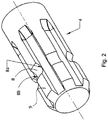
Fig. 2 is a perspective view, the -
Fig. 3 is a longitudinal view, the -
Fig. 3 a is a section along B-B ofFig. 3 and the -
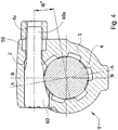
Fig. 4 is a second cross section.
-
-
Fig. 1 shows theshaped pin 3 with a distal cylindrical surface coupling with and sliding into atransverse hole 2 and shows a threaded axial hole 5 adapted to receive a tractionsocket head screw 6 whosehead 6a is substantially contained within the perimeter of the device. By means of the applied clamping action through thesocket head screw 6 theshaped pin 3 is dragged along thetransverse hole 2 up to realize in a point C a clamping contact between its lower surface (3a inFig. 3 ) and thetoroidal groove 8 formed on a tooth, not visible in the figure, of theshaft 4 where the vertical median plane B-B of the yoke and the median plane A-A of the tooth are angularly spaced by a negative angle α ranging from 5° to 15°. The recesses receiving the teeth of theshaft 4 are shown by 90. -
Fig. 2 shows thesplined drive shaft 4 with itsteeth 9 and with atoroidal groove 8 in which thelower surface 3a of theshaped pin 3, not shown in the figure, will engage. The contact between thesharp edges 8a of thegroove 8 and theshaped pin 3 is avoided. -
Fig. 3 shows ashaped pin 3 with the threaded axial hole 5a partially occupied by the tractionsocket head screw 6b. Thebottom part 3a suitable for engaging in the groove of a PTO tooth and the distalcylindrical portion 3b suitable to slide in thehole 2 are visible. -
Fig. 3 a shows theparts Fig. 3 . -
Fig. 4 shows how thehub 1 of a yoke Y has atransverse hole 2 in which ashaped pin 60 is housed which bears on theproximal end 60a alongitudinal screw thread 50 on which anut 6c is screwed that clamps thehub 1 on theshaft 4, also in this solution the condition of the angle α between the plane A - A of the tooth and the plane B - B of the yoke is respected.
Claims (4)
- Device for eliminating the axial and radial play in a connection between a hub (1) and a power take off (4) in a mechanical transmission in which the hub (1) has a transverse hole (2) that receives in sliding condition a clamping pin (3) characterized in that are comprised:- the transverse hole (2) in the hub (1) of a yoke (Y) in which hole a shaped pin (3) is received in sliding condition, the lower surface (3a) of the sliding pin that faces the power take off (4) engaging in a groove (8) of a power take off tooth (9);- a longitudinal hole in the hub (1) whose vertical median plane (B-B) is angularly spaced of a negative angle (α) with respect to the median plane (A-A) of the tooth (9),- a threaded axial cavity (5) in the shaped pin (3);- a traction screw (6) screwed into said threaded axial cavity (5) suitable for dragging the shaped pin (3) to create the desired clamping of the hub (1) on the power take off (4) through a contact between the shaped pin (3) and the surface of a groove (8).
- Device according to claim 1 characterized in that the negative angle (α) ranges from 5° to 15°.
- Device according to claims 1, 2 characterized in that the head (6a) of the traction screw (6) is substantially contained within the perimeter of the device.
- Device according to claim 1 characterized in that the shaped pin (60) is provided with a longitudinal thread (50) into its proximal portion on which thread a nut (6c) is screwed that drags the shaped pin (60) in engagement with the power take off (4).
Priority Applications (1)
| Application Number | Priority Date | Filing Date | Title |
|---|---|---|---|
| EP16425099.5A EP3315809A1 (en) | 2016-10-25 | 2016-10-25 | Device suitable for eliminating the axial and radial play in a connection between a shaft and a mechanical transmission hub |
Applications Claiming Priority (1)
| Application Number | Priority Date | Filing Date | Title |
|---|---|---|---|
| EP16425099.5A EP3315809A1 (en) | 2016-10-25 | 2016-10-25 | Device suitable for eliminating the axial and radial play in a connection between a shaft and a mechanical transmission hub |
Publications (1)
| Publication Number | Publication Date |
|---|---|
| EP3315809A1 true EP3315809A1 (en) | 2018-05-02 |
Family
ID=57570223
Family Applications (1)
| Application Number | Title | Priority Date | Filing Date |
|---|---|---|---|
| EP16425099.5A Withdrawn EP3315809A1 (en) | 2016-10-25 | 2016-10-25 | Device suitable for eliminating the axial and radial play in a connection between a shaft and a mechanical transmission hub |
Country Status (1)
| Country | Link |
|---|---|
| EP (1) | EP3315809A1 (en) |
Citations (4)
| Publication number | Priority date | Publication date | Assignee | Title |
|---|---|---|---|---|
| IT1198976B (en) | 1984-12-07 | 1988-12-21 | Edi Bondioli | LOCKING DEVICE BETWEEN HUB AND SHAFT PROVIDED WITH ANULAR STOP THROAT |
| JPH07317793A (en) * | 1994-05-31 | 1995-12-08 | Fuji Kiko Co Ltd | Universal joint shaft tightening structure |
| US5580184A (en) * | 1995-04-28 | 1996-12-03 | The Torrington Company | Angular adjustable clamp yoke |
| WO1998006953A1 (en) * | 1996-08-14 | 1998-02-19 | Edi Bondioli | Fork for mechanical transmission with splined shaft |
-
2016
- 2016-10-25 EP EP16425099.5A patent/EP3315809A1/en not_active Withdrawn
Patent Citations (4)
| Publication number | Priority date | Publication date | Assignee | Title |
|---|---|---|---|---|
| IT1198976B (en) | 1984-12-07 | 1988-12-21 | Edi Bondioli | LOCKING DEVICE BETWEEN HUB AND SHAFT PROVIDED WITH ANULAR STOP THROAT |
| JPH07317793A (en) * | 1994-05-31 | 1995-12-08 | Fuji Kiko Co Ltd | Universal joint shaft tightening structure |
| US5580184A (en) * | 1995-04-28 | 1996-12-03 | The Torrington Company | Angular adjustable clamp yoke |
| WO1998006953A1 (en) * | 1996-08-14 | 1998-02-19 | Edi Bondioli | Fork for mechanical transmission with splined shaft |
Similar Documents
| Publication | Publication Date | Title |
|---|---|---|
| US8590417B1 (en) | Trailer landing gear apparatus | |
| US9618051B2 (en) | Method and apparatus for mounting a machine element onto a shaft | |
| US8020472B2 (en) | Nut capturing socket assembly | |
| US20110079484A1 (en) | Quick disconnect coupling | |
| US20170101124A1 (en) | Steering Wheel Connection Assembly | |
| EP2805078B1 (en) | Shaft-hub coupling, adapter and drive motor | |
| KR20170009762A (en) | Fastener, fastening structure and fastening method | |
| EP3202533A1 (en) | Clamping device | |
| EP2905199A1 (en) | Coupling | |
| US20040182206A1 (en) | Noback bolt | |
| WO2016209854A1 (en) | Tightening tool for coaxial connectors | |
| US3752514A (en) | Socket retaining means | |
| US10145406B2 (en) | Self-locking screwing attachment devices and assemblies provided with same | |
| EP3740690A1 (en) | Drive device, having at least one clutch and one shaft | |
| CN108568772B (en) | Assembly comprising a support bracket for steering a counteracting torque and a powered screw drive | |
| DE102016209537A1 (en) | Brake pressure control device | |
| US4131039A (en) | Tightening force limiting device | |
| US20170312892A1 (en) | Screwing tool for an impact wrench for screwing wheel nuts onto and off from a hub body for securing a vehicle wheel, especially in motorsport, and an impact wrench | |
| US5243749A (en) | Transmission pump removal tool | |
| EP3740689A1 (en) | Drive device, comprising at least one clutch and a shaft | |
| CN206544133U (en) | A kind of electric screw driver of adjustable output torque | |
| DE102014002629B4 (en) | System for adjusting a bearing arrangement for a transmission with a tool | |
| US11458603B2 (en) | Tool for installing and removing a highly-torqued fastener | |
| DE102013100986A1 (en) | Screwdriver has sensor that is arranged for monitoring tool spindle in response to acceleration of tool spindle in axial direction, and controller for controlling drive based on sensor signal | |
| CN210034127U (en) | Drive shaft nut anti loosening structure |
Legal Events
| Date | Code | Title | Description |
|---|---|---|---|
| PUAI | Public reference made under article 153(3) epc to a published international application that has entered the european phase |
Free format text: ORIGINAL CODE: 0009012 |
|
| AK | Designated contracting states |
Kind code of ref document: A1 Designated state(s): AL AT BE BG CH CY CZ DE DK EE ES FI FR GB GR HR HU IE IS IT LI LT LU LV MC MK MT NL NO PL PT RO RS SE SI SK SM TR |
|
| AX | Request for extension of the european patent |
Extension state: BA ME |
|
| 17P | Request for examination filed |
Effective date: 20180914 |
|
| RBV | Designated contracting states (corrected) |
Designated state(s): AL AT BE BG CH CY CZ DE DK EE ES FI FR GB GR HR HU IE IS IT LI LT LU LV MC MK MT NL NO PL PT RO RS SE SI SK SM TR |
|
| 17Q | First examination report despatched |
Effective date: 20181015 |
|
| STAA | Information on the status of an ep patent application or granted ep patent |
Free format text: STATUS: THE APPLICATION IS DEEMED TO BE WITHDRAWN |
|
| 18D | Application deemed to be withdrawn |
Effective date: 20200603 |