EP3315792A1 - Hydraulic drive device and method for controlling same - Google Patents
Hydraulic drive device and method for controlling same Download PDFInfo
- Publication number
- EP3315792A1 EP3315792A1 EP16814100.0A EP16814100A EP3315792A1 EP 3315792 A1 EP3315792 A1 EP 3315792A1 EP 16814100 A EP16814100 A EP 16814100A EP 3315792 A1 EP3315792 A1 EP 3315792A1
- Authority
- EP
- European Patent Office
- Prior art keywords
- opening degree
- command value
- degree command
- pressure
- valve
- Prior art date
- Legal status (The legal status is an assumption and is not a legal conclusion. Google has not performed a legal analysis and makes no representation as to the accuracy of the status listed.)
- Withdrawn
Links
Images


Classifications
-
- F—MECHANICAL ENGINEERING; LIGHTING; HEATING; WEAPONS; BLASTING
- F15—FLUID-PRESSURE ACTUATORS; HYDRAULICS OR PNEUMATICS IN GENERAL
- F15B—SYSTEMS ACTING BY MEANS OF FLUIDS IN GENERAL; FLUID-PRESSURE ACTUATORS, e.g. SERVOMOTORS; DETAILS OF FLUID-PRESSURE SYSTEMS, NOT OTHERWISE PROVIDED FOR
- F15B11/00—Servomotor systems without provision for follow-up action; Circuits therefor
- F15B11/02—Systems essentially incorporating special features for controlling the speed or actuating force of an output member
- F15B11/024—Systems essentially incorporating special features for controlling the speed or actuating force of an output member by means of differential connection of the servomotor lines, e.g. regenerative circuits
-
- B—PERFORMING OPERATIONS; TRANSPORTING
- B29—WORKING OF PLASTICS; WORKING OF SUBSTANCES IN A PLASTIC STATE IN GENERAL
- B29B—PREPARATION OR PRETREATMENT OF THE MATERIAL TO BE SHAPED; MAKING GRANULES OR PREFORMS; RECOVERY OF PLASTICS OR OTHER CONSTITUENTS OF WASTE MATERIAL CONTAINING PLASTICS
- B29B7/00—Mixing; Kneading
- B29B7/02—Mixing; Kneading non-continuous, with mechanical mixing or kneading devices, i.e. batch type
- B29B7/22—Component parts, details or accessories; Auxiliary operations
-
- F—MECHANICAL ENGINEERING; LIGHTING; HEATING; WEAPONS; BLASTING
- F15—FLUID-PRESSURE ACTUATORS; HYDRAULICS OR PNEUMATICS IN GENERAL
- F15B—SYSTEMS ACTING BY MEANS OF FLUIDS IN GENERAL; FLUID-PRESSURE ACTUATORS, e.g. SERVOMOTORS; DETAILS OF FLUID-PRESSURE SYSTEMS, NOT OTHERWISE PROVIDED FOR
- F15B11/00—Servomotor systems without provision for follow-up action; Circuits therefor
- F15B11/02—Systems essentially incorporating special features for controlling the speed or actuating force of an output member
- F15B11/028—Systems essentially incorporating special features for controlling the speed or actuating force of an output member for controlling the actuating force
-
- F—MECHANICAL ENGINEERING; LIGHTING; HEATING; WEAPONS; BLASTING
- F15—FLUID-PRESSURE ACTUATORS; HYDRAULICS OR PNEUMATICS IN GENERAL
- F15B—SYSTEMS ACTING BY MEANS OF FLUIDS IN GENERAL; FLUID-PRESSURE ACTUATORS, e.g. SERVOMOTORS; DETAILS OF FLUID-PRESSURE SYSTEMS, NOT OTHERWISE PROVIDED FOR
- F15B13/00—Details of servomotor systems ; Valves for servomotor systems
- F15B13/02—Fluid distribution or supply devices characterised by their adaptation to the control of servomotors
- F15B13/04—Fluid distribution or supply devices characterised by their adaptation to the control of servomotors for use with a single servomotor
- F15B13/0401—Valve members; Fluid interconnections therefor
-
- B—PERFORMING OPERATIONS; TRANSPORTING
- B29—WORKING OF PLASTICS; WORKING OF SUBSTANCES IN A PLASTIC STATE IN GENERAL
- B29B—PREPARATION OR PRETREATMENT OF THE MATERIAL TO BE SHAPED; MAKING GRANULES OR PREFORMS; RECOVERY OF PLASTICS OR OTHER CONSTITUENTS OF WASTE MATERIAL CONTAINING PLASTICS
- B29B7/00—Mixing; Kneading
- B29B7/02—Mixing; Kneading non-continuous, with mechanical mixing or kneading devices, i.e. batch type
- B29B7/22—Component parts, details or accessories; Auxiliary operations
- B29B7/28—Component parts, details or accessories; Auxiliary operations for measuring, controlling or regulating, e.g. viscosity control
-
- B—PERFORMING OPERATIONS; TRANSPORTING
- B29—WORKING OF PLASTICS; WORKING OF SUBSTANCES IN A PLASTIC STATE IN GENERAL
- B29B—PREPARATION OR PRETREATMENT OF THE MATERIAL TO BE SHAPED; MAKING GRANULES OR PREFORMS; RECOVERY OF PLASTICS OR OTHER CONSTITUENTS OF WASTE MATERIAL CONTAINING PLASTICS
- B29B7/00—Mixing; Kneading
- B29B7/74—Mixing; Kneading using other mixers or combinations of mixers, e.g. of dissimilar mixers ; Plant
- B29B7/7476—Systems, i.e. flow charts or diagrams; Plants
- B29B7/7495—Systems, i.e. flow charts or diagrams; Plants for mixing rubber
-
- F—MECHANICAL ENGINEERING; LIGHTING; HEATING; WEAPONS; BLASTING
- F15—FLUID-PRESSURE ACTUATORS; HYDRAULICS OR PNEUMATICS IN GENERAL
- F15B—SYSTEMS ACTING BY MEANS OF FLUIDS IN GENERAL; FLUID-PRESSURE ACTUATORS, e.g. SERVOMOTORS; DETAILS OF FLUID-PRESSURE SYSTEMS, NOT OTHERWISE PROVIDED FOR
- F15B11/00—Servomotor systems without provision for follow-up action; Circuits therefor
- F15B11/08—Servomotor systems without provision for follow-up action; Circuits therefor with only one servomotor
- F15B11/10—Servomotor systems without provision for follow-up action; Circuits therefor with only one servomotor in which the servomotor position is a function of the pressure also pressure regulators as operating means for such systems, the device itself may be a position indicating system
-
- F—MECHANICAL ENGINEERING; LIGHTING; HEATING; WEAPONS; BLASTING
- F15—FLUID-PRESSURE ACTUATORS; HYDRAULICS OR PNEUMATICS IN GENERAL
- F15B—SYSTEMS ACTING BY MEANS OF FLUIDS IN GENERAL; FLUID-PRESSURE ACTUATORS, e.g. SERVOMOTORS; DETAILS OF FLUID-PRESSURE SYSTEMS, NOT OTHERWISE PROVIDED FOR
- F15B19/00—Testing; Calibrating; Fault detection or monitoring; Simulation or modelling of fluid-pressure systems or apparatus not otherwise provided for
- F15B19/007—Simulation or modelling
-
- F—MECHANICAL ENGINEERING; LIGHTING; HEATING; WEAPONS; BLASTING
- F15—FLUID-PRESSURE ACTUATORS; HYDRAULICS OR PNEUMATICS IN GENERAL
- F15B—SYSTEMS ACTING BY MEANS OF FLUIDS IN GENERAL; FLUID-PRESSURE ACTUATORS, e.g. SERVOMOTORS; DETAILS OF FLUID-PRESSURE SYSTEMS, NOT OTHERWISE PROVIDED FOR
- F15B13/00—Details of servomotor systems ; Valves for servomotor systems
- F15B13/02—Fluid distribution or supply devices characterised by their adaptation to the control of servomotors
- F15B13/04—Fluid distribution or supply devices characterised by their adaptation to the control of servomotors for use with a single servomotor
- F15B13/0401—Valve members; Fluid interconnections therefor
- F15B2013/041—Valve members; Fluid interconnections therefor with two positions
-
- F—MECHANICAL ENGINEERING; LIGHTING; HEATING; WEAPONS; BLASTING
- F15—FLUID-PRESSURE ACTUATORS; HYDRAULICS OR PNEUMATICS IN GENERAL
- F15B—SYSTEMS ACTING BY MEANS OF FLUIDS IN GENERAL; FLUID-PRESSURE ACTUATORS, e.g. SERVOMOTORS; DETAILS OF FLUID-PRESSURE SYSTEMS, NOT OTHERWISE PROVIDED FOR
- F15B21/00—Common features of fluid actuator systems; Fluid-pressure actuator systems or details thereof, not covered by any other group of this subclass
- F15B21/08—Servomotor systems incorporating electrically operated control means
- F15B21/087—Control strategy, e.g. with block diagram
-
- F—MECHANICAL ENGINEERING; LIGHTING; HEATING; WEAPONS; BLASTING
- F15—FLUID-PRESSURE ACTUATORS; HYDRAULICS OR PNEUMATICS IN GENERAL
- F15B—SYSTEMS ACTING BY MEANS OF FLUIDS IN GENERAL; FLUID-PRESSURE ACTUATORS, e.g. SERVOMOTORS; DETAILS OF FLUID-PRESSURE SYSTEMS, NOT OTHERWISE PROVIDED FOR
- F15B2211/00—Circuits for servomotor systems
- F15B2211/30—Directional control
- F15B2211/305—Directional control characterised by the type of valves
- F15B2211/30505—Non-return valves, i.e. check valves
-
- F—MECHANICAL ENGINEERING; LIGHTING; HEATING; WEAPONS; BLASTING
- F15—FLUID-PRESSURE ACTUATORS; HYDRAULICS OR PNEUMATICS IN GENERAL
- F15B—SYSTEMS ACTING BY MEANS OF FLUIDS IN GENERAL; FLUID-PRESSURE ACTUATORS, e.g. SERVOMOTORS; DETAILS OF FLUID-PRESSURE SYSTEMS, NOT OTHERWISE PROVIDED FOR
- F15B2211/00—Circuits for servomotor systems
- F15B2211/30—Directional control
- F15B2211/305—Directional control characterised by the type of valves
- F15B2211/30525—Directional control valves, e.g. 4/3-directional control valve
-
- F—MECHANICAL ENGINEERING; LIGHTING; HEATING; WEAPONS; BLASTING
- F15—FLUID-PRESSURE ACTUATORS; HYDRAULICS OR PNEUMATICS IN GENERAL
- F15B—SYSTEMS ACTING BY MEANS OF FLUIDS IN GENERAL; FLUID-PRESSURE ACTUATORS, e.g. SERVOMOTORS; DETAILS OF FLUID-PRESSURE SYSTEMS, NOT OTHERWISE PROVIDED FOR
- F15B2211/00—Circuits for servomotor systems
- F15B2211/30—Directional control
- F15B2211/305—Directional control characterised by the type of valves
- F15B2211/3056—Assemblies of multiple valves
- F15B2211/30565—Assemblies of multiple valves having multiple valves for a single output member, e.g. for creating higher valve function by use of multiple valves like two 2/2-valves replacing a 5/3-valve
- F15B2211/3058—Assemblies of multiple valves having multiple valves for a single output member, e.g. for creating higher valve function by use of multiple valves like two 2/2-valves replacing a 5/3-valve having additional valves for interconnecting the fluid chambers of a double-acting actuator, e.g. for regeneration mode or for floating mode
-
- F—MECHANICAL ENGINEERING; LIGHTING; HEATING; WEAPONS; BLASTING
- F15—FLUID-PRESSURE ACTUATORS; HYDRAULICS OR PNEUMATICS IN GENERAL
- F15B—SYSTEMS ACTING BY MEANS OF FLUIDS IN GENERAL; FLUID-PRESSURE ACTUATORS, e.g. SERVOMOTORS; DETAILS OF FLUID-PRESSURE SYSTEMS, NOT OTHERWISE PROVIDED FOR
- F15B2211/00—Circuits for servomotor systems
- F15B2211/30—Directional control
- F15B2211/31—Directional control characterised by the positions of the valve element
- F15B2211/3144—Directional control characterised by the positions of the valve element the positions being continuously variable, e.g. as realised by proportional valves
-
- F—MECHANICAL ENGINEERING; LIGHTING; HEATING; WEAPONS; BLASTING
- F15—FLUID-PRESSURE ACTUATORS; HYDRAULICS OR PNEUMATICS IN GENERAL
- F15B—SYSTEMS ACTING BY MEANS OF FLUIDS IN GENERAL; FLUID-PRESSURE ACTUATORS, e.g. SERVOMOTORS; DETAILS OF FLUID-PRESSURE SYSTEMS, NOT OTHERWISE PROVIDED FOR
- F15B2211/00—Circuits for servomotor systems
- F15B2211/30—Directional control
- F15B2211/32—Directional control characterised by the type of actuation
- F15B2211/327—Directional control characterised by the type of actuation electrically or electronically
-
- F—MECHANICAL ENGINEERING; LIGHTING; HEATING; WEAPONS; BLASTING
- F15—FLUID-PRESSURE ACTUATORS; HYDRAULICS OR PNEUMATICS IN GENERAL
- F15B—SYSTEMS ACTING BY MEANS OF FLUIDS IN GENERAL; FLUID-PRESSURE ACTUATORS, e.g. SERVOMOTORS; DETAILS OF FLUID-PRESSURE SYSTEMS, NOT OTHERWISE PROVIDED FOR
- F15B2211/00—Circuits for servomotor systems
- F15B2211/30—Directional control
- F15B2211/35—Directional control combined with flow control
- F15B2211/351—Flow control by regulating means in feed line, i.e. meter-in control
-
- F—MECHANICAL ENGINEERING; LIGHTING; HEATING; WEAPONS; BLASTING
- F15—FLUID-PRESSURE ACTUATORS; HYDRAULICS OR PNEUMATICS IN GENERAL
- F15B—SYSTEMS ACTING BY MEANS OF FLUIDS IN GENERAL; FLUID-PRESSURE ACTUATORS, e.g. SERVOMOTORS; DETAILS OF FLUID-PRESSURE SYSTEMS, NOT OTHERWISE PROVIDED FOR
- F15B2211/00—Circuits for servomotor systems
- F15B2211/30—Directional control
- F15B2211/365—Directional control combined with flow control and pressure control
-
- F—MECHANICAL ENGINEERING; LIGHTING; HEATING; WEAPONS; BLASTING
- F15—FLUID-PRESSURE ACTUATORS; HYDRAULICS OR PNEUMATICS IN GENERAL
- F15B—SYSTEMS ACTING BY MEANS OF FLUIDS IN GENERAL; FLUID-PRESSURE ACTUATORS, e.g. SERVOMOTORS; DETAILS OF FLUID-PRESSURE SYSTEMS, NOT OTHERWISE PROVIDED FOR
- F15B2211/00—Circuits for servomotor systems
- F15B2211/40—Flow control
- F15B2211/405—Flow control characterised by the type of flow control means or valve
- F15B2211/40507—Flow control characterised by the type of flow control means or valve with constant throttles or orifices
-
- F—MECHANICAL ENGINEERING; LIGHTING; HEATING; WEAPONS; BLASTING
- F15—FLUID-PRESSURE ACTUATORS; HYDRAULICS OR PNEUMATICS IN GENERAL
- F15B—SYSTEMS ACTING BY MEANS OF FLUIDS IN GENERAL; FLUID-PRESSURE ACTUATORS, e.g. SERVOMOTORS; DETAILS OF FLUID-PRESSURE SYSTEMS, NOT OTHERWISE PROVIDED FOR
- F15B2211/00—Circuits for servomotor systems
- F15B2211/60—Circuit components or control therefor
- F15B2211/63—Electronic controllers
- F15B2211/6303—Electronic controllers using input signals
- F15B2211/6306—Electronic controllers using input signals representing a pressure
- F15B2211/6309—Electronic controllers using input signals representing a pressure the pressure being a pressure source supply pressure
-
- F—MECHANICAL ENGINEERING; LIGHTING; HEATING; WEAPONS; BLASTING
- F15—FLUID-PRESSURE ACTUATORS; HYDRAULICS OR PNEUMATICS IN GENERAL
- F15B—SYSTEMS ACTING BY MEANS OF FLUIDS IN GENERAL; FLUID-PRESSURE ACTUATORS, e.g. SERVOMOTORS; DETAILS OF FLUID-PRESSURE SYSTEMS, NOT OTHERWISE PROVIDED FOR
- F15B2211/00—Circuits for servomotor systems
- F15B2211/60—Circuit components or control therefor
- F15B2211/63—Electronic controllers
- F15B2211/6303—Electronic controllers using input signals
- F15B2211/6306—Electronic controllers using input signals representing a pressure
- F15B2211/6313—Electronic controllers using input signals representing a pressure the pressure being a load pressure
-
- F—MECHANICAL ENGINEERING; LIGHTING; HEATING; WEAPONS; BLASTING
- F15—FLUID-PRESSURE ACTUATORS; HYDRAULICS OR PNEUMATICS IN GENERAL
- F15B—SYSTEMS ACTING BY MEANS OF FLUIDS IN GENERAL; FLUID-PRESSURE ACTUATORS, e.g. SERVOMOTORS; DETAILS OF FLUID-PRESSURE SYSTEMS, NOT OTHERWISE PROVIDED FOR
- F15B2211/00—Circuits for servomotor systems
- F15B2211/60—Circuit components or control therefor
- F15B2211/63—Electronic controllers
- F15B2211/6303—Electronic controllers using input signals
- F15B2211/6336—Electronic controllers using input signals representing a state of the output member, e.g. position, speed or acceleration
-
- F—MECHANICAL ENGINEERING; LIGHTING; HEATING; WEAPONS; BLASTING
- F15—FLUID-PRESSURE ACTUATORS; HYDRAULICS OR PNEUMATICS IN GENERAL
- F15B—SYSTEMS ACTING BY MEANS OF FLUIDS IN GENERAL; FLUID-PRESSURE ACTUATORS, e.g. SERVOMOTORS; DETAILS OF FLUID-PRESSURE SYSTEMS, NOT OTHERWISE PROVIDED FOR
- F15B2211/00—Circuits for servomotor systems
- F15B2211/60—Circuit components or control therefor
- F15B2211/63—Electronic controllers
- F15B2211/6303—Electronic controllers using input signals
- F15B2211/6346—Electronic controllers using input signals representing a state of input means, e.g. joystick position
-
- F—MECHANICAL ENGINEERING; LIGHTING; HEATING; WEAPONS; BLASTING
- F15—FLUID-PRESSURE ACTUATORS; HYDRAULICS OR PNEUMATICS IN GENERAL
- F15B—SYSTEMS ACTING BY MEANS OF FLUIDS IN GENERAL; FLUID-PRESSURE ACTUATORS, e.g. SERVOMOTORS; DETAILS OF FLUID-PRESSURE SYSTEMS, NOT OTHERWISE PROVIDED FOR
- F15B2211/00—Circuits for servomotor systems
- F15B2211/60—Circuit components or control therefor
- F15B2211/665—Methods of control using electronic components
- F15B2211/6653—Pressure control
-
- F—MECHANICAL ENGINEERING; LIGHTING; HEATING; WEAPONS; BLASTING
- F15—FLUID-PRESSURE ACTUATORS; HYDRAULICS OR PNEUMATICS IN GENERAL
- F15B—SYSTEMS ACTING BY MEANS OF FLUIDS IN GENERAL; FLUID-PRESSURE ACTUATORS, e.g. SERVOMOTORS; DETAILS OF FLUID-PRESSURE SYSTEMS, NOT OTHERWISE PROVIDED FOR
- F15B2211/00—Circuits for servomotor systems
- F15B2211/60—Circuit components or control therefor
- F15B2211/665—Methods of control using electronic components
- F15B2211/6654—Flow rate control
-
- F—MECHANICAL ENGINEERING; LIGHTING; HEATING; WEAPONS; BLASTING
- F15—FLUID-PRESSURE ACTUATORS; HYDRAULICS OR PNEUMATICS IN GENERAL
- F15B—SYSTEMS ACTING BY MEANS OF FLUIDS IN GENERAL; FLUID-PRESSURE ACTUATORS, e.g. SERVOMOTORS; DETAILS OF FLUID-PRESSURE SYSTEMS, NOT OTHERWISE PROVIDED FOR
- F15B2211/00—Circuits for servomotor systems
- F15B2211/60—Circuit components or control therefor
- F15B2211/665—Methods of control using electronic components
- F15B2211/6656—Closed loop control, i.e. control using feedback
-
- F—MECHANICAL ENGINEERING; LIGHTING; HEATING; WEAPONS; BLASTING
- F15—FLUID-PRESSURE ACTUATORS; HYDRAULICS OR PNEUMATICS IN GENERAL
- F15B—SYSTEMS ACTING BY MEANS OF FLUIDS IN GENERAL; FLUID-PRESSURE ACTUATORS, e.g. SERVOMOTORS; DETAILS OF FLUID-PRESSURE SYSTEMS, NOT OTHERWISE PROVIDED FOR
- F15B2211/00—Circuits for servomotor systems
- F15B2211/70—Output members, e.g. hydraulic motors or cylinders or control therefor
- F15B2211/705—Output members, e.g. hydraulic motors or cylinders or control therefor characterised by the type of output members or actuators
- F15B2211/7051—Linear output members
- F15B2211/7053—Double-acting output members
- F15B2211/7054—Having equal piston areas
-
- F—MECHANICAL ENGINEERING; LIGHTING; HEATING; WEAPONS; BLASTING
- F15—FLUID-PRESSURE ACTUATORS; HYDRAULICS OR PNEUMATICS IN GENERAL
- F15B—SYSTEMS ACTING BY MEANS OF FLUIDS IN GENERAL; FLUID-PRESSURE ACTUATORS, e.g. SERVOMOTORS; DETAILS OF FLUID-PRESSURE SYSTEMS, NOT OTHERWISE PROVIDED FOR
- F15B2211/00—Circuits for servomotor systems
- F15B2211/70—Output members, e.g. hydraulic motors or cylinders or control therefor
- F15B2211/76—Control of force or torque of the output member
-
- F—MECHANICAL ENGINEERING; LIGHTING; HEATING; WEAPONS; BLASTING
- F15—FLUID-PRESSURE ACTUATORS; HYDRAULICS OR PNEUMATICS IN GENERAL
- F15B—SYSTEMS ACTING BY MEANS OF FLUIDS IN GENERAL; FLUID-PRESSURE ACTUATORS, e.g. SERVOMOTORS; DETAILS OF FLUID-PRESSURE SYSTEMS, NOT OTHERWISE PROVIDED FOR
- F15B2211/00—Circuits for servomotor systems
- F15B2211/80—Other types of control related to particular problems or conditions
- F15B2211/86—Control during or prevention of abnormal conditions
- F15B2211/8609—Control during or prevention of abnormal conditions the abnormal condition being cavitation
Landscapes
- Engineering & Computer Science (AREA)
- Mechanical Engineering (AREA)
- Physics & Mathematics (AREA)
- Fluid Mechanics (AREA)
- General Engineering & Computer Science (AREA)
- Fluid-Pressure Circuits (AREA)
Abstract
Description
- The present invention relates to a hydraulic drive device and a method for controlling the same.
- Hitherto, as a drive device commonly used in an industrial machine, and the like, a hydraulic drive device has been known. The hydraulic drive device includes a cylinder, a piston, a rod, a hydraulic pump, a valve, and a tank. In this device, a hydraulic oil discharged from the hydraulic pump is supplied to a head chamber or a rod chamber of the cylinder by the switching of the valve. A pressure of the hydraulic oil at that time allows the piston and the rod to move in a reciprocating manner.
- Such a hydraulic drive device is used, for example, for a kneader which kneads rubber for a tire. Specifically, a drive portion (ram) which kneads rubber is connected to a top end of the rod, and the ram kneads rubber in accordance with a reciprocating movement of the piston and the rod.
- Incidentally, a kneading quality in a kneader for a tire rubber depends on whether a ram is pushed onto rubber as a target constantly at a desired pressure and speed (uniformization of an agitation effect on rubber), and to achieve the same, in a hydraulic cylinder system, an extremely high pressure control performance is required.
- Incidentally, in such a hydraulic drive device, depending on an operation situation of the ram, a volume expansion of the head chamber of the cylinder fails to be followed by a flow rate of the hydraulic oil supplied to the head chamber from the hydraulic pump, which may generate a negative pressure in the head chamber. In such a case, cavitation occurs in the head chamber, and hydraulic equipment and a hydraulic circuit may suffer from various troubles.
- As a technique for preventing such a problem (negative pressure generated in the head chamber), a hydraulic drive device as described in Patent Document 1 has been known. The hydraulic drive device described in Patent Document 1 includes two respective hydraulic pumps which can supply a hydraulic oil independently of each other to a head chamber and a rod chamber of a cylinder. These hydraulic pumps are each controlled in an independent manner, thereby preventing a head pressure from becoming a negative pressure regardless of an operation situation of a load connected to a rod.
- In the hydraulic drive device as described in Patent Document 1, the two pumps are each required to be controlled in an independent manner so that the control over the whole device becomes complicated.
- Patent Document 1:
JP 2001-214903 A - An object of the present invention is to provide a hydraulic drive device having a simple structure which can prevent a negative pressure from being generated in a head chamber, and a control method to follow changes in a control characteristic caused due to the structure.
- A hydraulic drive device according to one aspect of the present invention includes a cylinder; a rod expandable and contractible with respect to the cylinder; a piston which is connected to the rod and divides the cylinder internally into a rod chamber and a head chamber; a hydraulic pump which delivers a hydraulic oil to the cylinder; a tank which stores the hydraulic oil flown from the cylinder; a valve switchable between a positive state in which the hydraulic pump and the head chamber are connected to each other and the rod chamber and the tank are connected to each other and a negative state in which the hydraulic pump and the rod chamber are connected to each other and the head chamber and the tank are connected to each other; and a merging flow passage which allows at least a portion of the hydraulic oil from the rod chamber toward the tank to be merged into the hydraulic oil from the hydraulic pump toward the head chamber when the valve is in the positive state.
- A method for controlling a hydraulic drive device according to one aspect of the present invention, in which the hydraulic drive device includes: a cylinder; a rod expandable and contractible with respect to the cylinder; a piston which is connected to the rod and divides the cylinder internally into a rod chamber and a head chamber; a hydraulic pump which delivers a hydraulic oil to the cylinder; a tank which stores the hydraulic oil flown from the cylinder; a valve switchable between a positive state in which the hydraulic pump and the head chamber are connected to each other and the rod chamber and the tank are connected to each other and a negative state in which the hydraulic pump and the rod chamber are connected to each other and the head chamber and the tank are connected to each other; and a merging flow passage which allows at least a portion of the hydraulic oil from the rod chamber toward the tank to be merged into the hydraulic oil from the hydraulic pump toward the head chamber when the valve is in the positive state, includes: a determination step of determining whether or not an inflow condition which indicates that the hydraulic oil flows into the head chamber through the merging flow passage is satisfied; and an opening degree command value calculation step of calculating the opening degree command value on the basis of a predetermined relational expression and transmitting the opening degree command value to the valve when it is determined in the determination step that the inflow condition is satisfied, and calculating the opening degree command value on the basis of a relational expression different from the predetermined relational expression and transmitting the opening degree command value to the valve when it is not determined in the determination step that the inflow condition is satisfied.
-
- [
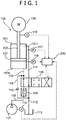
FIG. 1] FIG. 1 is a diagram schematically illustrating a hydraulic drive device according to a first embodiment of the present invention. - [
FIG. 2] FIG. 2 is a diagram schematically illustrating the hydraulic drive device according to the first embodiment of the present invention. - [
FIG. 3] FIG. 3 is a block diagram of a control unit of the hydraulic drive device as illustrated inFIG. 1 . - [
FIG. 4] FIG. 4 is a graph illustrating a relationship between an opening degree command value and a flow rate of a hydraulic oil. - [
FIG. 5] FIG. 5 is a graph illustrating a relationship between the opening degree command value and a piston speed. - [
FIG. 6] FIG. 6 is a flowchart of the control unit as illustrated inFIG. 3 . - [
FIG. 7] FIG. 7 is a block diagram of the control unit of the hydraulic drive device according to a second embodiment of the present invention. - [
FIG. 8] FIG. 8 is a graph illustrating a relationship between the opening degree command value and the piston speed when the opening degree command value is a positive value and a head pressure is greater than or equal to a threshold value. - [
FIG. 9] FIG. 9 is a graph illustrating a relationship between the opening degree command value and the piston speed when the opening degree command value is a positive value and the head pressure is less than the threshold value. - [
FIG. 10] FIG. 10 is a graph illustrating a relationship between the opening degree command value and the piston speed when the opening degree command value is a negative value. - [
FIG. 11] FIG. 11 is a flowchart of the control unit as illustrated inFIG. 7 . - [
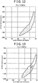
FIG. 12] FIG. 12 is a graph illustrating a relationship between the opening degree command value and the piston speed when a target cylinder pressure is 5 MPa. - [
FIG. 13] FIG. 13 is a graph illustrating a relationship between the opening degree command value and the piston speed when the target cylinder pressure is 3 MPa. - [
FIG. 14] FIG. 14 is a graph illustrating a relationship between the opening degree command value and the piston speed when the target cylinder pressure is 8 MPa. - [
FIG. 15] FIG. 15 is a block diagram of a control unit of the hydraulic drive device according to a third embodiment of the present invention. - [
FIG.16] FIG. 16 is a flowchart of the control unit as illustrated inFIG. 15 . - [
FIG. 17] FIG. 17 is a block diagram of a control unit of the hydraulic drive device according to a fourth embodiment of the present invention. - [
FIG.18] FIG. 18 is a flowchart of the control unit as illustrated inFIG. 17 . - Hereinafter, preferred embodiments of the present invention will be described with reference to the drawings.
- A hydraulic drive device according to a first embodiment of the present invention will be described with reference to
FIGS. 1 to 6 . - As illustrated in
FIGS. 1 and2 , the present hydraulic drive device includes ahydraulic unit 100 and acontrol unit 200. Thehydraulic unit 100 includes acylinder 101, arod 103, apiston 102, ahydraulic pump 107, atank 113, avalve 106, and a mergingflow passage 114. - The
cylinder 101 is a pressure vessel having a cylindrical shape. Thecylinder 101 is disposed in such a posture that a center axis of thecylinder 101 is vertical. Thiscylinder 101 is internally divided by thepiston 102 into arod chamber 101r and ahead chamber 101h. - The
rod 103 is held by thecylinder 101 so as to be expandable and contractible (in a vertical direction) with respect to thecylinder 101 along an axial direction of thecylinder 101. A base end of therod 103 is positioned inside thecylinder 101, and a top end of therod 103 is positioned outside thecylinder 101. To the top end of therod 103, aload 105 is connected. In the present embodiment, to the top end of therod 103, a ram for kneading rubber is connected as theload 105. - The
piston 102 is connected to the base end of therod 103. Thepiston 102 is formed into a disk shape. Thepiston 102 divides thecylinder 101 internally into therod chamber 101r in which therod 103 is positioned and thehead chamber 101h. - The
hydraulic pump 107 delivers a hydraulic oil into the cylinder 101 (therod chamber 101r and thehead chamber 101h). - The
tank 113 stores the hydraulic oil flown from thecylinder 101. - The
valve 106 performs switching between a positive state (state shown inFIG. 1 ) in which thehydraulic pump 107 and thehead chamber 101h are connected to each other and therod chamber 101r and thetank 113 are connected to each other and a negative state (a state shown inFIG. 2 ) in which thehydraulic pump 107 and therod chamber 101r are connected to each other and thehead chamber 101h and thetank 113 are connected to each other. Specifically, thevalve 106, in the positive state, connects a pumpconnection flow passage 108 and a head chamberconnection flow passage 110 to each other and connects a rod chamberconnection flow passage 111 and a tankconnection flow passage 112 to each other. On the other hand, thevalve 106, in the negative state, connects the pumpconnection flow passage 108 and the rod chamberconnection flow passage 111 to each other and connects the head chamberconnection flow passage 110 and the tankconnection flow passage 112 to each other. - When the
valve 106 is in the positive state, the hydraulic oil as discharged from thehydraulic pump 107 flows through the pumpconnection flow passage 108 and the head chamberconnection flow passage 110 into thehead chamber 101h, and accordingly a pressure of this hydraulic oil allows thepiston 102 and therod 103 to move up. At this time, the hydraulic oil in therod chamber 101r flows through the rod chamberconnection flow passage 111 and the tankconnection flow passage 112 into thetank 113. On the contrary, when thevalve 106 is in the negative state, the hydraulic oil as discharged from thehydraulic pump 107 flows through the pumpconnection flow passage 108 and the rod chamberconnection flow passage 111 into therod chamber 101r, and accordingly a pressure of this hydraulic oil allows thepiston 102 and therod 103 to move down. At this time, the hydraulic oil in thehead chamber 101h flows through the head chamberconnection flow passage 110 and the tankconnection flow passage 112 into thetank 113. In the present embodiment, a reciprocating movement of thepiston 102 and therod 103 in the vertical direction as described above allows the ram to knead rubber. Note that the pumpconnection flow passage 108 is provided with anadjustment valve 109 for rectification. - The merging
flow passage 114 allows at least a portion of the hydraulic oil from therod chamber 101r toward thetank 113 to be merged into the hydraulic oil from thehydraulic pump 107 toward thehead chamber 101h. Specifically, an upstream side end portion of the mergingflow passage 114 is connected to the tankconnection flow passage 112, and a downstream side end portion of the mergingflow passage 114 is connected to the head chamberconnection flow passage 110. The mergingflow passage 114 is provided with acheck valve 115. - The
control unit 200 controls an opening degree of thevalve 106. Specifically, thecontrol unit 200 calculates an opening degree command value for determining an opening degree of thevalve 106 and transmits this opening degree command value to thevalve 106. Thecontrol unit 200 is constituted by a computer, such as a personal computer and a programmable logic controller, provided to be annexed to thehydraulic unit 100, and in the interior of this computer, processes a signal in accordance with a flowchart (a program) as illustrated inFIG. 6 . As illustrated inFIG. 3 , thecontrol unit 200 includes adetermination portion 210 and an opening degree commandvalue calculation portion 215. - The
determination portion 210 determines whether or not an inflow condition which indicates that the hydraulic oil flows into thehead chamber 101h through the mergingflow passage 114 is satisfied. In the present embodiment, thedetermination portion 210 determines that the inflow condition is satisfied when a reference opening degree command value ASV which is the opening degree command value of thevalve 106 when a target cylinder pressure Psv is obtained is a positive value (a value at which thevalve 106 is in the positive state). The target cylinder pressure Psv is a target and a cylinder pressure PPV calculated on the basis of a head pressure PhPV (a pressure of the hydraulic oil which is applied to thehead chamber 101h) and a rod pressure PrPV (a pressure of the hydraulic oil which is applied to therod chamber 101r). Note that a cylinder pressure is the rod pressure PrPV minus the head pressure PhPV multiplied by a ratio of a pressure receiving area on the side of arod chamber 101r to a pressure receiving area of thehead chamber 101h of thepiston 102. Moreover, the head pressure PhPV is detected by apressure sensor 116 which can detect a pressure of thehead chamber 101h and the rod pressure PrPV is detected by apressure sensor 117 which can detect a pressure of therod chamber 101r. - Herein, a reason for employing the reference opening degree command value ASV as an index for determining whether or not the inflow condition is satisfied is as follows. In short, when the reference opening degree command value ASV is a positive value, the valve is in the positive state (in a phase in which a volume of the
head chamber 101h increases) and thus it can be considered that a negative pressure is likely to be generated in thehead chamber 101h, in other words, the hydraulic oil is likely to flow into thehead chamber 101h through the mergingflow passage 114. Thus, it is possible to determine that the inflow condition is satisfied when the reference opening degree command value ASV is a positive value. - The opening degree command
value calculation portion 215 calculates the opening degree command value on the basis of a predetermined relational expression and transmits this opening degree command value to thevalve 106 when thedetermination portion 210 determines that the inflow condition is satisfied, and calculates the opening degree command value on the basis of a relational expression different from the predetermined relational expression and transmits this opening degree command value to thevalve 106 when thedetermination portion 210 determines that the inflow condition is not satisfied. In the present embodiment, the opening degree commandvalue calculation portion 215 transmits a value less than the reference opening degree command value ASV as the opening degree command value to thevalve 106 when thedetermination portion 210 determines that the inflow condition is satisfied, and transmits the reference opening degree command value ASV to thevalve 106 when thedetermination portion 210 determines that the inflow condition is not satisfied. A reason therefor will be later described. The opening degree commandvalue calculation portion 215 includes a reference opening degree commandvalue calculation portion 220 and an opening degree commandvalue correction portion 230. - The reference opening degree command
value calculation portion 220 calculates the reference opening degree command value ASV (the opening degree command value of thevalve 106 when the target cylinder pressure Psv is obtained). Specifically, the reference opening degree commandvalue calculation portion 220 calculates a flow rate command value Vsv which is a flow rate of the hydraulic oil that is required for obtaining the target cylinder pressure Psv on the basis of the target cylinder pressure Psv and the cylinder pressure PPV (measured values) using a feedback control law, such as a PID controller, and calculates the reference opening degree command value ASV on the basis of a relationship between the flow rate command value Vsv and the reference opening degree command value ASV (seeFIG. 4 ). Note that the relationship as illustrated inFIG. 4 is determined in advance under no load and under a condition in which the hydraulic oil does not flow into thehead chamber 101h through the mergingflow passage 114. - The opening degree command
value correction portion 230 corrects the reference opening degree command value ASV to a value less than this reference opening degree command value ASV and transmits this value as the opening command value to thevalve 106. Specifically, the opening degree commandvalue correction portion 230 transmits to thevalve 106 the reference opening degree command value ASV multiplied by an inclination ratio aoff/aon of a negative side inclination aoff to a positive side inclination aon as an opening degree command value A*SV as represented by the below formula (1).
[Mathematical Formula 1]
- Herein, the negative side inclination aoff indicates an inclination represented by a ratio of an increment in a piston speed (a displacement speed of the piston 102) to an increment in the opening degree command value when this opening degree command value is a negative value. Moreover, the positive side inclination aon indicates an inclination represented by a ratio of an increment in the piston speed to an increment in the opening degree command value when this opening degree command value is a positive value.
-
FIG. 5 illustrates a scatter plot of operation data with respect to a relationship between the opening degree command value and the piston speed. InFIG. 5 , the horizontal axis indicates a measured value of the opening degree command value and the vertical axis indicates the piston speed. InFIG. 5 , a region at a right side of the horizontal axis with respect to the origin is a region when thevalve 106 is in the positive state and thedetermination portion 210 determines that the inflow condition is satisfied. On the other hand, inFIG. 5 , a region at a left side of the horizontal axis with respect to the origin is a region when thevalve 106 is in the negative state and thedetermination portion 210 determines that the inflow condition is not satisfied. Astraight line 52 indicated inFIG. 5 is a linear approximate straight line approximated in such a manner as to pass the origin on the basis of aplot 50 of measured value data when thevalve 106 is in the negative state. Similarly, astraight line 53 indicated inFIG. 5 is a linear approximate straight line approximated in such a manner as to pass the origin on the basis of aplot 51 of measured value data when thevalve 106 is in the positive state. In other words, an inclination of thestraight line 52 corresponds to the negative side inclination aoff and an inclination of thestraight line 53 corresponds to the positive side inclination aon. Note that each of the linear approximatestraight lines - From
FIG. 5 , it is apparent that the positive side inclination aon is greater than the negative side inclination aoff. Thus, the opening degree commandvalue calculation portion 215 transmits to the valve 106 a value less than the reference opening degree command value ASV, i.e., the reference opening degree command value ASV multiplied by the inclination ratio aoff/aon as the opening degree command value A*SV as represented by the above formula (1) when thedetermination portion 210 determines that the inflow condition is satisfied. Specifically, as illustrated inFIG. 3 , when the reference opening degree command value ASV which is anoutput signal 3 from the reference opening degree commandvalue calculation portion 220 is inputted to thedetermination portion 210, and adetermination result signal 4 outputted from thedetermination portion 210 is a signal indicating that the reference opening degree command value ASV is a positive value, switching to a circuit in which the reference opening degree command value ASV outputted from the reference opening degree commandvalue calculation portion 220 is inputted to the opening degree commandvalue correction portion 230 is performed. On the other hand, when thedetermination result signal 4 outputted from thedetermination portion 210 is a signal indicating that the reference opening degree command value ASV is a negative value, switching to a circuit in which the reference opening degree command value ASV outputted from the reference opening degree commandvalue calculation portion 220 is inputted as it is to thevalve 106 of thehydraulic unit 100 is performed. - The control process of the
control unit 200 as described above will be described with reference to a flowchart as illustrated inFIG. 6 . - When the present hydraulic drive device is driven (when a supply of the hydraulic oil from the
hydraulic pump 107 is started), first, parameters calculated in the past are initialized (step S1000). At this time, a measured value 1 of the hydraulic unit 100 (the cylinder pressure PPV inclusive) is inputted to the reference opening degree commandvalue calculation portion 220 of thecontrol unit 200. Then, the reference opening degree commandvalue calculation portion 220 calculates the reference opening degree command value ASV on the basis of asignal 2 including the target cylinder pressure Psv and the measured value 1 (step S100). This reference opening degree command value ASV is inputted to thedetermination portion 210. - Subsequently, the
determination portion 210 determines whether or not the reference opening degree command value ASV is a positive value (step S1200). As a result, when the reference opening degree command value ASV is a positive value (YES at step S1200), the opening degree commandvalue correction portion 230 of the opening degree commandvalue calculation portion 215 calculates the opening degree command value A*SV on the basis of the above formula (1) (step S1300) and transmits this value (a signal 5) to thevalve 106. On the other hand, when the reference opening degree command value ASV is a negative value (NO at step S1200), the opening degree commandvalue calculation portion 215 transmits the reference opening degree command value ASV (the signal 3) to thevalve 106. Then, on the basis of this value, thevalve 106 is controlled (step S1400). - Next, the
control unit 200 determines whether or not a predetermined termination condition is satisfied (step S1500). As a result, when the termination condition is satisfied (YES at step S1500), the control is terminated, and when the termination condition is not satisfied (NO at step S1500), a return to step S1100 is performed. - When the hydraulic drive device as described above is driven, the
valve 106 performs switching between the positive state and the negative state, whereby thepiston 102 and therod 103 repeats a reciprocating movement in the vertical direction. Thereby, the load 105 (the ram) kneads rubber. - Herein, although an action of the repulsive force, the inertial force, and the like applied from a
load 105 side occasionally causes the head pressure PhPV to be decreased when thevalve 106 is in the positive state, in the present embodiment, in such a case, at least a portion of the hydraulic oil from therod chamber 101r toward thetank 113 flows into thehead chamber 101h through the mergingflow passage 114. Accordingly, the head pressure PhPV is prevented from becoming a negative pressure during an operation of the device. In other words, in the present embodiment, such a simple structure as to be provided with the mergingflow passage 114 can prevent cavitation from occurring in thehead chamber 101h. - Moreover, in the above embodiment, the opening degree command
value calculation portion 215 calculates the opening degree command value on the basis of a predetermined relational expression and transmits this opening degree command value to thevalve 106 when thedetermination portion 210 determines that the inflow condition is satisfied, and calculates the opening degree command value on the basis of a relational expression different from the predetermined relational expression and transmits this opening degree command value to thevalve 106 when thedetermination portion 210 does not determine that the inflow condition is satisfied. - Accordingly, destabilization of a reciprocating movement of the
piston 102 and the rod 103 (a vertical movement in the present embodiment) is prevented. Specifically, the opening degree command value different depending on whether the inflow condition is determined to be satisfied or not determined to be satisfied is transmitted to thevalve 106, so that as compared with a case in which the same opening degree command value is transmitted to thevalve 106 regardless of whether or not the inflow condition is satisfied, a reciprocating movement of thepiston 102 and therod 103 is stabilized. - Further, in the above embodiment, the opening degree command
value calculation portion 215 transmits a value less than the reference opening degree command value ASV as the opening degree command value to thevalve 106 when thedetermination portion 210 determines that the inflow condition is satisfied, and transmits the reference opening degree command value ASV to thevalve 106 when thedetermination portion 210 determines that the inflow condition is not satisfied. - In this aspect, when the reference opening degree command value ASV is a positive value, in other words, when it is feared that the hydraulic oil flows into the
head chamber 101h through the mergingflow passage 114, a value less than the reference opening degree command value ASV at which the target cylinder pressure Psv is obtained is transmitted as the opening degree command value to the valve 106 (an opening degree of thevalve 106 is set to an opening degree less than an opening degree at which the target cylinder pressure Psv is obtained). Accordingly, disturbance of the relationship between the opening degree command value and a flow rate of the oil passing the valve 106 (a flow rate of the oil flowing into thehead chamber 101h) is prevented, whereby destabilization of a reciprocating movement of therod 103 is prevented. - Specifically, the opening degree command
value calculation portion 215 transmits to thevalve 106 the reference opening degree command value ASV multiplied by the inclination ratio aoff/aon as the opening degree command value A*SV when thedetermination portion 210 determines that the inflow condition is satisfied. - Thus, the relationship between the opening degree command value and a flow rate of the hydraulic oil flowing into the
head chamber 101h when the reference opening degree command value ASV is a positive value is substantially identical to that when the reference opening degree command value ASV is a negative value, so that destabilization of a reciprocating movement of therod 103 is further prevented. - Next, the hydraulic drive device according to a second embodiment of the present invention will be described with reference to
FIGS. 7 to 11 . Note that in the second embodiment, description will be made only on parts different from those in the first embodiment, and description of a configuration, action, and effects identical to those in the first embodiment is omitted. - In the present embodiment, a logic of determination by the
determination portion 210 and a manner to correct the reference opening degree command value ASV by the opening degree commandvalue calculation portion 215 are mainly different. Specifically, the opening degree commandvalue calculation portion 215 transmits to thevalve 106 the reference opening degree command value ASV multiplied by a first inclination ratio abase/a1 as the opening degree command value when thedetermination portion 210 determines that the inflow condition is satisfied and the head pressure PhPV is greater than or equal to a threshold value. On the other hand, the opening degree commandvalue calculation portion 215 transmits to thevalve 106 the reference opening degree command value multiplied by a second inclination ratio abase/a2 as the opening degree command value when thedetermination portion 210 determines that the inflow condition is satisfied and the head pressure PhPV is less than the threshold value. Then, the opening degree commandvalue calculation portion 215 transmits the reference opening degree command value ASV to thevalve 106 when thedetermination portion 210 determines that the inflow condition is not satisfied. - Herein, the threshold value is set to a value greater than the head pressure when the hydraulic oil flows into the
head chamber 101h through the mergingflow passage 114. - The first inclination ratio abase/a1 indicates a ratio of a negative side inclination abase to a first positive side inclination a1. The negative side inclination abase is an inclination represented by a ratio of an increment in a displacement speed of the
rod 103 to an increment in the opening degree command value when the opening degree command value is a negative value. The first positive side inclination a1 is an inclination represented by a ratio of an increment in a displacement speed of therod 103 to an increment in the opening degree command value when the opening degree command value is a positive value and the head pressure PhPV is greater than or equal to the threshold value, and is an inclination greater than the negative side inclination abase. - The second inclination ratio abase/a2 indicates a ratio of the negative side inclination abase to a second positive side inclination a2. The second positive side inclination a2 is an inclination represented by a ratio of an increment in a displacement speed of the
rod 103 to an increment in the opening degree command value when the opening degree command value is a positive value and the head pressure PhPV is less than the threshold value, and is an inclination greater than the negative side inclination abase. - In the present embodiment, as illustrated in
FIG. 7 , to thedetermination portion 210, the head pressure PhPV included in the measured value 1 of thehydraulic unit 100 and the reference opening degree command value ASV which is an output signal from the reference opening degree commandvalue calculation portion 220 are inputted. Thedetermination portion 210 determines whether or not the reference opening degree command value ASV is a positive value and whether or not the head pressure PhPV is greater than or equal to the threshold value. Specifically, thedetermination portion 210 outputs a first signal when the reference opening degree command value ASV is a positive value and the head pressure PhPV is greater than or equal to the threshold value, outputs a second signal when the reference opening degree command value ASV is a positive value and the head pressure PhPV is less than the threshold value, and outputs a third signal when the reference opening degree command value ASV is a negative value. - The opening degree command
value correction portion 230 includes a first opening degree commandvalue correction portion 231 and a second opening degree commandvalue correction portion 232. - The first opening degree command
value correction portion 231 corrects the reference opening degree command value ASV to a value less than this reference opening degree command value ASV and transmits this value (a signal 5) as the opening command value to thevalve 106. Specifically, the first opening degree commandvalue correction portion 231 transmits to thevalve 106 the reference opening degree command value ASV multiplied by the first inclination ratio abase/a1 of the negative side inclination abase to the first positive side inclination a1 as the opening degree command value A*SV as represented by the below formula (2).
[Mathematical Formula 2]
- The second opening degree command
value correction portion 232 corrects the reference opening degree command value ASV to a value less than this reference opening degree command value ASV and transmits this value (a signal 6) as the opening command value to thevalve 106. Specifically, the second opening degree commandvalue correction portion 232 transmits to thevalve 106 the reference opening degree command value ASV multiplied by the second inclination ratio abase/a2 of the negative side inclination abase to the second positive side inclination a2 as the opening degree command value A*SV as represented by the below formula (3).
[Mathematical Formula 3]
-
FIG. 8 illustrates a scatter plot of operation data when thevalve 106 is in the positive state (the opening degree command value is a positive value) and the head pressure PhPV is greater than or equal to the threshold value. Astraight line 61 indicated inFIG. 8 is a linear approximate straight line approximated in such a manner as to pass the origin on the basis of aplot 60 of measured value data. In other words, an inclination of thisstraight line 61 corresponds to the first positive side inclination a1. -
FIG. 9 illustrates a scatter plot of operation data when thevalve 106 is in the positive state (the opening degree command value is a positive value) and the head pressure PhPV is less than the threshold value. Astraight line 63 indicated inFIG. 9 is a linear approximate straight line approximated in such a manner as to pass the origin on the basis of aplot 62 of measured value data. In other words, an inclination of thisstraight line 63 corresponds to the second positive side inclination a2. -
FIG. 10 illustrates a scatter plot of operation data when thevalve 106 is in the negative state (when the opening degree command value is a negative value). Astraight line 65 indicated inFIG. 10 is a linear approximate straight line approximated in such a manner as to pass the origin on the basis of aplot 64 of measured value data. In other words, an inclination of thisstraight line 65 corresponds to the negative side inclination abase. Note that the negative side inclination abase is identical to the negative side inclination aoff in the first embodiment. - From
FIGS. 8 to 10 , it is apparent that the first positive side inclination a1 and the second positive side inclination a2 are greater than the negative side inclination aoff, and the second positive side inclination a2 is larger than the first positive side inclination a1. Thus, the opening degree commandvalue calculation portion 215 transmits to thevalve 106 the reference opening degree command value ASV multiplied by the first inclination ratio abase/a1 as the opening degree command value A*SV as represented by the above formula (2) when thedetermination portion 210 determines that the inflow condition is satisfied and the head pressure PhPV is greater than or equal to the threshold value. In other words, the first signal outputted by thedetermination portion 210 is used as a signal for switching to a circuit in which the opening degree command value ASV which is theoutput signal 3 from the reference opening degree commandvalue calculation portion 220 is inputted to the first opening degree commandvalue correction portion 231. Moreover, the opening degree commandvalue calculation portion 215 transmits to thevalve 106 the reference opening degree command value ASV multiplied by the second inclination ratio abase/a2 as the opening degree command value A*SV as represented by the above formula (3) when thedetermination portion 210 determines that the inflow condition is satisfied and the head pressure PhPV is less than the threshold value. In other words, the second signal outputted by thedetermination portion 210 is used as a signal for switching to a circuit in which the opening degree command value ASV which is the output signal from the reference opening degree commandvalue calculation portion 220 is inputted to the second opening degree commandvalue correction portion 232. Then, the opening degree commandvalue calculation portion 215 transmits the opening degree command value ASV to thevalve 106 when thedetermination portion 210 determines that the inflow condition is not satisfied. In other words, the third signal outputted by thedetermination portion 210 is used as a signal for switching to a circuit in which the opening degree command value ASV which is the output signal from the reference opening degree commandvalue calculation portion 220 is inputted as it is to thevalve 106 of thehydraulic unit 100. - The control process of the
control unit 200 as described above will be described with reference to a flowchart as illustrated inFIG. 11 . - Step S2000, step S2100, and step S2200 are respectively identical to step S1000, step S1100, and step S1200 in the first embodiment.
- In the present embodiment, when the reference opening degree command value ASV is a positive value (YES at step S2200), the
determination portion 210 determines whether or not the head pressure PhPV is greater than or equal to the threshold value (step S2300). As a result, when the head pressure PhPV is greater than or equal to the threshold value (YES at step S2300), the first opening degree commandvalue correction portion 231 of the opening degree commandvalue calculation portion 215 calculates the opening degree command value A*SV on the basis of the above formula (2) (step S2400) and transmits this value to thevalve 106. On the other hand, when the head pressure PhPV is less than the threshold value (NO at step S2300), the second opening degree commandvalue correction portion 232 of the opening degree commandvalue calculation portion 215 calculates the opening degree command value A*SV on the basis of the above formula (3) (step S2500) and transmits this value to thevalve 106. - Moreover, when the reference opening degree command value ASV is a negative value (NO at step S2200), the opening degree command
value calculation portion 215 transmits the reference opening degree command value ASV to thevalve 106. - On the basis of the command values A*SV, ASV calculated as described above, the
valve 106 is controlled (step S2500). - Subsequent step S2700 is identical to step S1500 in the first embodiment.
- As described above, in the present embodiment, the opening degree command
value calculation portion 215 transmits to thevalve 106 the reference opening degree command value ASV multiplied by a first inclination ratio abase/a1 as the opening degree command value when thedetermination portion 210 determines that the inflow condition is satisfied and the head pressure PhPV is greater than or equal to the threshold value, and transmits to thevalve 106 the reference opening degree command value ASV multiplied by a second inclination ratio abase/a2 as the opening degree command value when thedetermination portion 210 determines that the inflow condition is satisfied and the head pressure PhPV is less than the threshold value. - Accordingly, destabilization of a reciprocating movement of the
rod 103 is further reliably prevented. Specifically, the second positive side inclination a2 is greater than the first positive side inclination a1, so that when the head pressure PhPV is greater than or equal to the threshold value and when the head pressure PhPV is less than the threshold value, the reference opening degree command value ASV is multiplied by respective inclination ratios, whereby destabilization of a reciprocating movement of therod 103 is further prevented. - Next, the hydraulic drive device according to a third embodiment of the present invention will be described with reference to
FIGS. 12 to 16 . Note that in the third embodiment, description will be made only on parts different from those in the first embodiment and the second embodiment, and description of a structure, working, and effects identical to those in the first embodiment and the second embodiment is omitted. - In the first embodiment and the second embodiment, the reference opening degree command value ASV is multiplied by the inclination ratio such that the positive side inclinations aon, and a1 and a2 when the reference opening degree command value ASV is a positive value are respectively equal to the negative side inclinations aoff and abase when the reference opening degree command value ASV is a negative value, whereby the opening degree command value is calculated.
- However, the relationship between the opening degree command value and a flow rate of the oil passing the
valve 106 changes in accordance with not only the reference opening degree command value ASV but also the other factors. For example, as illustrated inFIGS. 12 to 14 , the relationship differs in accordance with a value of the target cylinder pressure Psv. Consequently, the control based on the particular target cylinder pressure Psv as in the first embodiment and the second embodiment insufficiently follows changes in the target cylinder pressure Psv. - Accordingly, in the third embodiment, a model formula in consideration of factors which influence the relationship is constructed and on the basis of the model formula, the opening degree command value is calculated. In further detail, as the model formula, a first module formula which represents a relationship between the rod pressure PrPV and the opening degree command value and a second model formula which represents a relationship between the cylinder pressure PPV and the opening degree command value are constructed, and on the basis of these model formulas, the opening degree command value is calculated.
- Herein, a reason for constructing the first model formula in consideration of the rod pressure PrPV and the second model formula in consideration of the cylinder pressure PPV is as follows. In short, since when the head pressure PhPV becomes less than or equal to a predetermined value, the hydraulic oil flows into the
head chamber 101h through the mergingflow passage 114, the head pressure remains at a substantially constant value while the hydraulic oil flows into thehead chamber 101h through the mergingflow passage 114. Thus, when the head pressure PhPV is greater than or equal to a threshold value which is greater than a value thereof, it is considered that inflow of the hydraulic oil into thehead chamber 101h through the mergingflow passage 114 and occurrence of cavitation substantially fail to happen. Accordingly, when the head pressure PhPV is greater than or equal to the threshold value, both the head pressure PhPV and the rod pressure PrPV are reliable, so that desirably, the opening degree command value is calculated on the basis of the second model formula based on the cylinder pressure PPV calculated on the basis of both the head pressure PhPV and the rod pressure PrPV. On the other hand, when the head pressure PhPV is less than the threshold value, in other words, when it is feared that cavitation occurs in thehead chamber 101h, the head pressure PhPV is not very reliable, so that desirably, the opening degree command value is calculated on the basis of the first model formula based on the rod pressure PrPV which is reliable. - Thus, it is possible to flexibly follow changes in factors which influence the relationship and realize the control having a further high versatility. Hereinafter, the present embodiment will be described in detail.
- As illustrated in
FIG. 15 , acontrol unit 201 includes adetermination portion 211 and an opening degree commandvalue calculation portion 216. - The
determination portion 211 determines whether or not the inflow condition is satisfied. In the present embodiment, to thedetermination portion 211, the head pressure PhPV from among information included in a measuredvalue 11 of thehydraulic unit 100 is inputted. Thedetermination portion 211 determines that the inflow condition is satisfied when the head pressure PhPV is less than the threshold value, and determines that the inflow condition is not satisfied when the head pressure PhPV is greater than or equal to the threshold value. Thedetermination portion 211 outputs a first signal when the head pressure PhPV is less than the threshold value (when determining that the inflow condition is satisfied), and outputs a second signal when the head pressure PhPV is greater than or equal to the threshold value (when determining that the inflow condition is not satisfied). - Herein, a reason for employing the head pressure PhPV as an index for determining whether or not the inflow condition is satisfied is as follows. In short, when the head pressure PhPV is greater than or equal to the threshold value which is greater than a value thereof, it is considered that inflow of the hydraulic oil into the
head chamber 101h through the mergingflow passage 114 and occurrence of cavitation in thehead chamber 101h substantially fail to happen. On the other hand, when the head pressure PhPV is less than the threshold value, it is possible to determine that the inflow condition is satisfied. - The opening degree command
value calculation portion 216 calculates the reference opening degree command value ASV on the basis of the first model formula when thedetermination portion 211 determines that the inflow condition is satisfied, and calculates the reference opening degree command value ASV on the basis of the second model formula when thedetermination portion 211 determines that the inflow condition is not satisfied. Specifically, the opening degree commandvalue calculation portion 216 includes a pressure differentiation commandvalue calculation unit 221, a first opening degree commandvalue calculation portion 241 which calculates the reference opening degree command value ASV on the basis of the first model formula, and a second opening degree commandvalue calculation portion 242 which calculates the reference opening degree command value ASV on the basis of the second model formula. - The pressure differentiation command
value calculation unit 221 calculates a pressure differentiation command value P'sv represented by the target cylinder pressure Psv minus the cylinder pressure PPV (a measured value). Specifically, as illustrated inFIG. 15 , to the pressure differentiation commandvalue calculation unit 221, asignal 12 including the target cylinder pressure Psv and the measured value 11 (the cylinder pressure PPV inclusive) are inputted, and the pressure differentiation commandvalue calculation unit 221 calculates the pressure differentiation command value P'sv on the basis of the below formula (4).
[Mathematical Formula 4]
- The second opening degree command
value calculation portion 242 calculates the opening degree command value ASV on the basis of the second formula representing the relationship between the cylinder pressure PPV and the opening degree command value, and transmits the opening degree command value ASV (a signal 16) to thevalve 106 when thedetermination portion 211 determines that the inflow condition is not satisfied. In other words, the second signal outputted by thedetermination portion 211 is used as a signal for switching to a circuit in which the pressure differentiation command value P'sv which is anoutput signal 13 from the pressure differentiation commandvalue calculation unit 221 is inputted to the second opening degree commandvalue calculation portion 242. A reason for employing the cylinder pressure PPV as a factor for calculating the opening degree command value ASV in the second model formula is as follows. In short, when the head pressure PhPV is greater than or equal to the threshold value, both the head pressure PhPV and the rod pressure PrPV are reliable so that the second opening degree commandvalue calculation portion 242 calculates the opening degree command value ASV on the basis of the second model formula including the cylinder pressure PPV calculated on the basis of both the head pressure PhPV and the rod pressure PrPV. - As illustrated in
FIG. 15 , to the second opening degree commandvalue calculation portion 242, in addition to the pressure differentiation command value P'sv which is theoutput signal 13 from the pressure differentiation commandvalue calculation unit 221, a measured value of an opening degree (hereinafter referred to as "opening degree measured value") of thevalve 106 from among information included in the measuredvalue 11 is inputted. The second opening degree commandvalue calculation portion 242 calculates the opening degree command value ASV on the basis of model formulas A consisting of the below formulas (5) to (7) when the opening degree measured value is a positive value, and calculates the opening degree command value ASV on the basis of model formulas B consisting of the below formulas (8) to (10) when the opening degree measured value is a negative value.
[Mathematical Formula 5]


- Herein, Sr denotes a pressure receiving area on the side of the
rod chamber 101r of thepiston 102, Sh denotes a pressure receiving area on the side of ahead chamber 101h of thepiston 102, vPV denotes a measured value of the piston speed (a rod speed), PrPV denotes a measured value of the rod pressure, PhPV denotes a measured value of the head pressure, Prmin denotes a minimum threshold value of the rod pressure, Phmin denotes a minimum threshold value of the head pressure, and PP denotes a pump pressure (a pressure of the hydraulic pump 107). Moreover, θ10, θ20, θ11, θ12, θ22, θ13, θ23, θ30, θ40, θ31, θ32, θ42, θ33, and θ43 are a coefficient for determining a model characteristic and can be determined using an approximation learning method, such as a least squares method. Note that the measured value vPV of the piston speed can be calculated, for example, by differentiation of aposition sensor 118 provided with therod 103. Moreover, the pump pressure is detected by apressure sensor 119 provided with thehydraulic pump 107. - The first opening degree command
value calculation portion 241 calculates the opening degree command value ASV on the basis of the first formula representing the relationship between the rod pressure PrPV and the opening degree command value, and transmits the opening degree command value ASV (a signal 15) to thevalve 106 when thedetermination portion 211 determines that the inflow condition is not satisfied. In other words, the first signal outputted by thedetermination portion 211 is used as a signal for switching to a circuit in which the pressure differentiation command value P'sv which is theoutput signal 13 from the pressure differentiation commandvalue calculation unit 221 is inputted to the first opening degree commandvalue calculation portion 241. A reason for employing the rod pressure PrPV in place of the cylinder pressure PPV as a factor for calculating the opening degree command value ASV in the first model formula is as follows. In short, when the head pressure PhPV is less than the threshold value, in other words, when it is feared that cavitation occurs in thehead chamber 101h, the head pressure PhPV is not very reliable, so that the first opening degree commandvalue calculation portion 241 calculates the opening degree command value ASV on the basis of the first model formula including the rod pressure PrPV which is reliable.. - As illustrated in
FIG. 15 , also to the first opening degree commandvalue calculation portion 241, in addition to the pressure differentiation command value P'sv which is theoutput signal 13 from the pressure differentiation commandvalue calculation unit 221, the opening degree measured value from among information included in the measuredvalue 11 is inputted. The first opening degree commandvalue calculation portion 241 calculates the opening degree command value ASV on the basis of a model formula C as represented by the below formula (11) when the opening degree measured value is a positive value, and calculates the opening degree command value ASV on the basis of a model formula D as represented by the below formula (12) when the opening degree measured value is a negative value.
[Mathematical Formula 11]

- Herein, P'rSV is a time differentiation value of the rod pressure as a target.
- The control process of the
control unit 201 as described above will be described with reference to a flowchart as illustrated inFIG. 16 . - When the present hydraulic drive device is driven (when a supply of the hydraulic oil from the
hydraulic pump 107 is started), first, parameters calculated in the past are initialized (step S3000). At this time, the cylinder pressure PPV from among information included in the measuredvalue 11 of thehydraulic unit 100 is inputted to the pressure differentiation commandvalue calculation unit 221, the head pressure PhPV from among information included in the measuredvalue 11 is inputted to thedetermination portion 211, and the opening degree measured value, the piston speed vPV, the pump pressure Pp, and the like from among the information included in the measuredvalue 11 are inputted to the first opening degree commandvalue calculation portion 241 and the second opening degree commandvalue calculation portion 242. - Next, the pressure differentiation command
value calculation unit 221 calculates the pressure differentiation command value P'sv on the basis of thesignal 12 including the target cylinder pressure Psv and the measured value 11 (step S3010). This pressure differentiation command value P'sv (the signal 13) is inputted to the first opening degree commandvalue calculation portion 241 and the second opening degree commandvalue calculation portion 242. - Subsequently, the
determination portion 211 determines whether or not the inflow condition is satisfied (whether or not the head pressure PhPV is less than the threshold value) (step S3020). As a result, when the head pressure PhPV is greater than or equal to the threshold value (YES at step S3020), the second opening degree commandvalue calculation portion 242 determines whether or not the opening degree measured value is a positive value (step S3030). Then, when the opening degree measured value is a positive value (YES at step S3030), the second opening degree commandvalue calculation portion 242 calculates the opening degree command value ASV on the basis of the model formulas A (step S3040) and transmits this value (the signal 16) to thevalve 106. On the other hand, when the opening degree measured value is a negative value (NO at step S3030), the second opening degree commandvalue calculation portion 242 calculates the opening degree command value ASV on the basis of the model formulas B (step S3050) and transmits this value (the signal 16) to thevalve 106. - Moreover, when the head pressure PhPV is less than the threshold value (NO at step S3020), the first opening degree command
value calculation portion 241 determines whether or not the opening degree measured value is a positive value (step S3060). Then, when the opening degree measured value is a positive value (YES at step S3060), the first opening degree commandvalue calculation portion 241 calculates the opening degree command value ASV on the basis of the model formula C (step S3070) and transmits this value (the signal 15) to thevalve 106. On the other hand, when the opening degree measured value is a negative value (NO at step S3060), the first opening degree commandvalue calculation portion 241 calculates the opening degree command value ASV on the basis of the model formula D (step S3080) and transmits this value (the signal 15) to thevalve 106. - On the basis of the opening degree command value ASV calculated as described above, the
valve 106 is controlled (step S3090). - Next, the
control unit 201 determines whether or not a predetermined termination condition is satisfied (step S3100). As a result, when the termination condition is satisfied (YES at step S3100), the control is terminated, and when the termination condition is not satisfied (NO at step S3100), a return to step S3010 is performed. - As described above, in the present embodiment, the
control unit 201 calculates the opening degree command value ASV on the basis of the first model formula (the model formulas C and D) including not the head pressure PhPV which is not reliable but the rod pressure PrPV which is reliable when the head pressure PhPV is less than the threshold value, in other words, when it is feared that cavitation occurs in thehead chamber 101h. On the other hand, thecontrol unit 201 calculates the opening degree command value ASV on the basis of the second model formula (the model formulas A and B) including the cylinder pressure PPV calculated on the basis of both the head pressure PhPV and the rod pressure PrPV, because both the head pressure PhPV and the rod pressure PrPV are reliable, when the head pressure PhPV is greater than or equal to the threshold value. Consequently, as compared with the first embodiment and the second embodiment, it is possible to calculate the opening degree command value ASV capable of flexibly following changes in factors which influence the relationship between the opening degree command value and a flow rate of the oil passing thevalve 106. Thus, destabilization of a reciprocating movement of thepiston 102 and therod 103 is further effectively prevented, and the versatility is further improved. - Moreover, in the present embodiment, the
control unit 201 calculates the opening degree command value ASV on the basis of the head pressure PhPV and the rod pressure PrPV as well as the pressure differentiation command value P'sv, the time differentiation value of the target rod pressure P'rSV, the piston speed vPV, the pump pressure Pp, a pressure difference between the pump pressure Pp and the rod pressure PrPV, and a pressure difference between the pump pressure Pp and the head pressure PhPV. Thus, the opening degree command value ASV is calculated more accurately. - Next, the hydraulic drive device according to a fourth embodiment of the present invention will be described with reference to
FIGS. 17 and18 . Note that in the fourth embodiment, description will be made only on parts different from those in the third embodiment, and description of a structure, working, and effects identical to those in the third embodiment and the second embodiment is omitted. - In the present embodiment, the time differentiation value of the target rod pressure P'rSV of the first model formula in the third embodiment is set to 0 (zero) so as to obtain a base opening degree command value A2, to which a correction command value A1 is separately added, whereby the opening degree command value ASV is calculated, and the pressure differentiation command value P'sv of the second model formula in the third embodiment is set to 0 (zero) so as to obtain the base opening degree command value A2, to which the correction command value A1 is separately added, whereby the opening degree command value ASV is calculated. Effects thus obtained are identical to those in the third embodiment. Hereinafter, the present embodiment will be described in detail.
- As illustrated in
FIG. 17 , acontrol unit 202 includes adetermination portion 212 and an opening degree commandvalue calculation portion 217. Note that thedetermination portion 212 is identical to thedetermination portion 211 in the third embodiment. - The opening degree command
value calculation portion 217 includes a zerosignal output unit 222, a first opening degree commandvalue calculation portion 251, a second opening degree commandvalue calculation portion 252, and a correction commandvalue calculation unit 253. - The zero
signal output unit 222 generates such asignal 23 that the time differentiation value of the target rod pressure P'rSV and the pressure differentiation command value P'sv are constantly 0 and outputs the same to the first opening degree commandvalue calculation portion 251 and the second opening degree commandvalue calculation portion 252. - The first opening degree command
value calculation portion 251 is identical to the first opening degree commandvalue calculation portion 241 in the third embodiment. Note thatsuch signal 23 that the time differentiation value of the target rod pressure P'rSV is 0 is inputted from the zerosignal output unit 222, and accordingly the first opening degree commandvalue calculation portion 251 calculates the base opening degree command value A2 (a signal 25) on the basis of thesignal 23 and the model formula C or the model formula D. - The second opening degree command
value calculation portion 252 is identical to the second opening degree commandvalue calculation portion 242 in the third embodiment. Note thatsuch signal 23 that the pressure differentiation command value P'sv is 0 is inputted from the zerosignal output unit 222, and accordingly the second opening degree commandvalue calculation portion 252 calculates the base opening degree command value A2 (a signal 26) on the basis of thesignal 23 and the model formulas A or the model formulas B. - The correction command
value calculation unit 253 calculates the correction command value A1 (a signal 27). Specifically, as illustrated inFIG. 17 , to the correction commandvalue calculation unit 253, a deviation between asignal 22 including the target cylinder pressure Psv and the measuredvalue 11 of the hydraulic unit 100 (the cylinder pressure PPV inclusive), in other words, a value calculated on the basis of the above formula (4) is inputted, and the correction commandvalue calculation unit 253 calculates the correction command value A2 (the signal 27) using the PID controller. - The control process of the
control unit 202 as described above will be described with reference to a flowchart as illustrated inFIG. 18 . - When the present hydraulic drive device is driven (when a supply of the hydraulic oil from the
hydraulic pump 107 is started), first, parameters calculated in the past are initialized (step S4000). At this time, the cylinder pressure PPV from among information included in the measuredvalue 21 of thehydraulic unit 100 is inputted to the correction commandvalue calculation unit 253, the head pressure PhPV from among information included in the measuredvalue 21 is inputted to thedetermination portion 212, and the opening degree measured value, the piston speed vPV, the pump pressure Pp, and the like from among the information included in the measuredvalue 21 are inputted to the first opening degree commandvalue calculation portion 251 and the second opening degree commandvalue calculation portion 252. - Next, the correction command
value calculation unit 253 calculates the correction command value A1 (the signal 27) on the basis of the deviation between thesignal 22 including the target cylinder pressure Psv and the measured value 21 (step S4010). - Step S4020, step S4030, and step S4060 are respectively identical to step S3020, step S3030, and step S3060 in the third embodiment. Moreover, step S4040, step S4050, step S4070, and step S4080 are respectively identical to step S3040, step S3050, step S3070, and step S3080 in the third embodiment except the following points.
- In other words, at step S4040, to the pressure differentiation command value P'sv of the formulas A, 0 is inputted, whereby the base opening degree command value A2 (the signal 26) is calculated. At step S4050, to the pressure differentiation command value P'sv of the formulas B, 0 is inputted, whereby the base opening degree command value A2 (the signal 26) is calculated. At step S4070, to the time differentiation value of the target rod pressure P'rSV of the formula C, 0 is inputted, whereby the base opening degree command value A2 (the signal 25) is calculated. At step S4080, to the time differentiation value of the target rod pressure P'rSV of the formula D, 0 is inputted, whereby the base opening degree command value A2 (the signal 25) is calculated.
- Then, to the base opening degree command value A2 (the
signal 25 or the signal 26) calculated at any of step S4040, step S4050, step S4070, and step S4080, the correction command value A1 (the signal 27) calculated at step S4010 is added, whereby the opening degree command value ASV (a signal 28) is calculated (step S4090). - On the basis of the opening degree command value ASV (the signal 28) calculated as described above, the
valve 106 is controlled (step S4100). - Next, the
control unit 202 determines whether or not a predetermined termination condition is satisfied (step S4110). As a result, when the termination condition is satisfied (YES at step S4110), the control is terminated, and when the termination condition is not satisfied (NO at step S4110), a return to step S4010 is performed. - As described above, in the present embodiment, without calculating the pressure differentiation command value P'sv and the time differentiation value of the target rod pressure P'rSV, the opening degree command value ASV can be calculated accurately similarly to the third embodiment.
- Note that the embodiments disclosed herein are a mere example from every aspect and should be understood as being nonlimitative. The scope of the present invention is defined not by the description of the above embodiments but by the claims, and includes meanings equivalent to the claims and any modifications within the claims.
- For example, in the above embodiments, as the
load 105, a ram for kneading rubber is described by way of example, but theload 105 is not limited to the ram. - Hereinafter, the above embodiments will be generally described.
- A hydraulic drive device according to the above embodiments includes a cylinder; a rod expandable and contractible with respect to the cylinder; a piston which is connected to the rod and divides the cylinder internally into a rod chamber and a head chamber; a hydraulic pump which delivers a hydraulic oil to the cylinder; a tank which stores the hydraulic oil flown from the cylinder; a valve switchable between a positive state in which the hydraulic pump and the head chamber are connected to each other and the rod chamber and the tank are connected to each other and a negative state in which the hydraulic pump and the rod chamber are connected to each other and the head chamber and the tank are connected to each other; and a merging flow passage which allows at least a portion of the hydraulic oil from the rod chamber toward the tank to be merged into the hydraulic oil from the hydraulic pump toward the head chamber when the valve is in the positive state.
- In the present hydraulic drive device, when a head pressure (a pressure of the hydraulic oil which is applied to the head chamber) is decreased while the valve is in the positive state, at least the part of the hydraulic oil from the rod chamber toward the tank flows into the head chamber through the merging flow passage, and accordingly, the head pressure is prevented from becoming a negative pressure. Thus, such a simple structure as to be provided with the merging flow passage can prevent cavitation from occurring in the head chamber.
- Incidentally, since there is a certain relationship between an opening degree command value for determining an opening degree of the valve and a flow rate of the hydraulic oil passing the valve (a flow rate of the hydraulic oil flowing into the head chamber), when the hydraulic oil flows into the head chamber through the merging flow passage, the hydraulic oil having a flow rate greater than or equal to a flow rate corresponding to the opening degree command value flows into the head chamber. In such a case, the certain relationship is disturbed. In other words, when the constant opening degree command value is transmitted to the valve regardless of whether or not the hydraulic oil flows into the head chamber through the merging flow passage, a reciprocating movement of the piston and the rod may be destabilized.
- Accordingly, the above hydraulic drive device further includes control unit which calculates an opening degree command value for determining an opening degree of the valve and transmits the opening degree command value to the valve. Preferably, the control unit includes: a determination portion which determines whether or not an inflow condition which indicates that the hydraulic oil flows into the head chamber through the merging flow passage is satisfied; and an opening degree command value calculation portion which calculates the opening degree command value on the basis of a predetermined relational expression and transmits the opening degree command value to the valve when the determination portion determines that the inflow condition is satisfied, and calculates the opening degree command value on the basis of a relational expression different from the predetermined relational expression and transmits the opening degree command value to the valve when the determination portion does not determine that the inflow condition is satisfied.
- Thus, destabilization of a reciprocating movement of the piston and the rod is prevented. Specifically, the opening degree command value different depending on whether the inflow condition is determined to be satisfied or not determined to be satisfied is transmitted to the valve so that as compared with a case in which the same opening degree command value is transmitted to the valve regardless of whether or not the inflow condition is satisfied, a reciprocating movement of the piston and the rod is stabilized.
- For example, the determination portion may determine that the inflow condition is satisfied when a reference opening degree command value is a positive value at which the valve is in the positive state, the reference opening degree command value being the opening degree command value of the valve when a target cylinder pressure is obtained, the target cylinder pressure being a target and a cylinder pressure calculated on the basis of a head pressure as a pressure of the hydraulic oil which is applied to the head chamber and a rod pressure as a pressure of the hydraulic oil which is applied to the rod chamber, and the opening degree command value calculation portion may transmit a value less than the reference opening degree command value as the opening degree command value to the valve when the determination portion determines that the inflow condition is satisfied, and transmit the reference opening degree command value to the valve when the determination portion determines that the inflow condition is not satisfied.
- Specifically, when the reference opening degree command value is a positive value, the valve is in the positive state (in a phase in which a volume of the head chamber increases) and thus it can be considered that a negative pressure is likely to be generated in the head chamber, in other words, the hydraulic oil is likely to flow into the head chamber through the merging flow passage. Thus, it is possible to determine that the inflow condition is satisfied when the reference opening degree command value is a positive value. Then, when the reference opening degree command value is a positive value, in other words, when it is feared that the hydraulic oil flows into the head chamber through the merging flow passage, a value less than the reference opening degree command value at which the target cylinder pressure is obtained is transmitted as the opening degree command value to the valve (an opening degree of the valve is set to an opening degree less than an opening degree at which the target cylinder pressure is obtained), so that disturbance of the certain relationship is prevented, whereby destabilization of a reciprocating movement of the rod is prevented.
- In such a case, the opening degree command value calculation portion may transmit the reference opening degree command value multiplied by an inclination ratio of a negative side inclination to a positive side inclination, as the opening degree command value to the valve when the determination portion determines that the inflow condition is satisfied, the negative side inclination being represented by a ratio of an increment in a displacement speed of the piston to an increment in the opening degree command value when the reference opening degree command value is a negative value, the positive side inclination being greater than the negative side inclination and being represented by a ratio of an increment in the displacement speed of the piston to an increment in the opening degree command value when the reference opening degree command value is a positive value.
- Thus, the relationship between the opening degree command value and a flow rate of the hydraulic oil flowing into the head chamber when the reference opening degree command value is a positive value is substantially identical to that when the reference opening degree command value is a negative value, so that destabilization of a reciprocating movement of the rod is further prevented. Generally, the positive side inclination (a ratio of an increment in the displacement speed of the piston to an increment in the opening degree command value when the reference opening degree command value is a positive value) is greater than the negative side inclination (a ratio of an increment in a displacement speed of the piston to an increment in the opening degree command value when the reference opening degree command value is a negative value). Accordingly, when the reference opening degree command value is a positive value, this reference opening degree command value is multiplied by the inclination ratio, whereby a displacement speed of the piston when the rod expands and a displacement speed of the piston when the rod contracts are substantially equal to each other, so that a reciprocating movement of the piston and the rod is stabilized.
- Alternatively, the opening degree command value calculation portion may transmit the reference opening degree command value multiplied by a first inclination ratio of a negative side inclination to a first positive side inclination, as the opening degree command value to the valve when the determination unit determination portion determines that the inflow condition is satisfied and the head pressure is greater than or equal to a threshold value, the threshold value being greater than the head pressure when the hydraulic oil flows into the head chamber through the merging flow passage, the negative side inclination being represented by a ratio of an increment in a displacement speed of the rod to an increment in the opening degree command value when the opening degree command value is a negative value, the first positive side inclination being greater than the negative side inclination and being an inclination represented by a ratio of an increment in a displacement speed of the rod to an increment in the opening degree command value when the opening degree command value is a positive value and the head pressure is greater than or equal to the threshold value, and transmit the reference opening degree command value multiplied by a second inclination ratio of the negative side inclination to a second positive side inclination, as the opening degree command value to the valve when the determination unit determination portion determines that the inflow condition is satisfied and the head pressure is less than the threshold value, the second positive side inclination being greater than the negative side inclination and being an inclination represented by a ratio of an increment in a displacement speed of the rod to an increment in the opening degree command value when the opening degree command value is a positive value and the head pressure is less than the threshold value.
- Accordingly, destabilization of a reciprocating movement of the rod is further reliably prevented. Specifically, the second positive side inclination is greater than the first positive side inclination so that when the head pressure is greater than or equal to the threshold value and when the head pressure is less than the threshold value, the reference opening degree command value is multiplied by respective inclination ratios, whereby destabilization of a reciprocating movement of the rod is further prevented.
- Moreover, for example, the determination portion may determine that the inflow condition is satisfied when a head pressure as a pressure of the hydraulic oil which is applied to the head chamber is less than a threshold value which is greater than the head pressure when the hydraulic oil flows into the head chamber through the merging flow passage, and the opening degree command value calculation portion may calculate the opening degree command value on the basis of a first model formula, as the relational expression, the first model formula representing a relationship between the opening degree command value and a rod pressure as a pressure of the hydraulic oil which is applied to the rod chamber, and transmits the opening degree command value to the valve when the determination portion determines that the inflow condition is satisfied, and calculate the opening degree command value on the basis of a second model formula, as a relational expression different from the relational expression, the second model formula representing a relationship between the opening degree command value and a cylinder pressure calculated on the basis of the head pressure and the rod pressure, and transmits the opening degree command value to the valve when the determination portion determines that the inflow condition is not satisfied.
- Specifically, since when the head pressure becomes less than or equal to a predetermined value, the hydraulic oil flows into the head chamber through the merging flow passage, the head pressure remains at a substantially constant value while the hydraulic oil flows into the head chamber through the merging flow passage. Thus, when the head pressure is greater than or equal to a threshold value which is greater than a value thereof, it is considered that inflow of the hydraulic oil into the head chamber through the merging flow passage and occurrence of cavitation in the head chamber substantially fail to happen. On the other hand, when the head pressure is less than the threshold value, it is possible to determine that the inflow condition is satisfied. Then, when the head pressure is less than the threshold value, in other words, when it is feared that cavitation occurs in the head chamber, the opening degree command value is calculated on the basis of the first model formula including not the head pressure which is not reliable but the rod pressure which is reliable. On the other hand, when the head pressure is greater than or equal to the threshold value, both the head pressure and the rod pressure are reliable so that the opening degree command value is calculated on the basis of the second model formula including both the head pressure and the rod pressure. Thus, the opening degree command value can be calculated accurately. Accordingly, destabilization of a reciprocating movement of the rod can be effectively prevented.
- In such a case, preferably, the opening degree command value calculation portion calculates the opening degree command value on the basis of a model formula, as the first model formula, the model formula representing a relationship between the rod pressure and a piston speed which is a displacement speed of the piston, and the opening degree command value, and transmits the opening degree command value to the valve when the determination portion determines that the inflow condition is satisfied, and calculates the opening degree command value on the basis of a model formula, as the second model formula, the model formula representing a relationship between the cylinder pressure and the piston speed, and the opening degree command value, and transmits the opening degree command value to the valve when the determination portion determines that the inflow condition is not satisfied.
- Thus, the opening degree command value can be calculated more accurately.
- Moreover, preferably, in the present hydraulic drive device, the opening degree command value calculation portion calculates the opening degree command value on the basis of a model formula, as the second model formula, the model formula representing a relationship between the opening degree command value and a target cylinder pressure minus the cylinder pressure, the target cylinder pressure being the cylinder pressure and a target, and transmits the opening degree command value to the valve when the determination portion determines that the inflow condition is not satisfied.
- Thus, the opening degree command value can be calculated further accurately.
- Moreover, a method for controlling a hydraulic drive device according to the above embodiments, in which the hydraulic drive device including: a cylinder; a rod expandable and contractible with respect to the cylinder; a piston which is connected to the rod and divides the cylinder internally into a rod chamber and a head chamber; a hydraulic pump which delivers a hydraulic oil to the cylinder; a tank which stores the hydraulic oil flown from the cylinder; a valve switchable between a positive state in which the hydraulic pump and the head chamber are connected to each other and the rod chamber and the tank are connected to each other and a negative state in which the hydraulic pump and the rod chamber are connected to each other and the head chamber and the tank are connected to each other; and a merging flow passage which allows at least a portion of the hydraulic oil from the rod chamber toward the tank to be merged into the hydraulic oil from the hydraulic pump toward the head chamber when the valve is in the positive state, includes: a determination step of determining whether or not an inflow condition which indicates that the hydraulic oil flows into the head chamber through the merging flow passage is satisfied; and an opening degree command value calculation step of calculating the opening degree command value on the basis of a predetermined relational expression and transmitting the opening degree command value to the valve when it is determined in the determination step that the inflow condition is satisfied, and calculating the opening degree command value on the basis of a relational expression different from the predetermined relational expression and transmitting the opening degree command value to the valve when it is not determined in the determination step that the inflow condition is satisfied.
- For example, in the determination step, it may be determined that the inflow condition is satisfied when a reference opening degree command value is a positive value at which the valve is in the positive state, the reference opening degree command value being the opening degree command value of the valve when a target cylinder pressure is obtained, the target cylinder pressure being a target and a cylinder pressure calculated on the basis of a head pressure as a pressure of the hydraulic oil which is applied to the head chamber and a rod pressure as a pressure of the hydraulic oil which is applied to the rod chamber, and in the opening degree command value calculation step, a value less than the reference opening degree command value may be transmitted as the opening degree command value to the valve when it is determined in the determination step that the inflow condition is satisfied, and the reference opening degree command value be transmitted to the valve when it is determined in the determination step that the inflow condition is not satisfied.
- Moreover, in the method for controlling the present hydraulic drive device, in the opening degree command value calculation step, the reference opening degree command value multiplied by an inclination ratio of a negative side inclination to a positive side inclination may be transmitted as the opening degree command value to the valve when it is determined in the determination step that the inflow condition is satisfied, the negative side inclination being represented by a ratio of an increment in a displacement speed of the piston to an increment in the opening degree command value when the reference opening degree command value is a negative value, the positive side inclination being greater than the negative side inclination and being represented by a ratio of an increment in the displacement speed of the piston to an increment in the opening degree command value when the reference opening degree command value is a positive value.
- Alternatively, in the opening degree command value calculation step, when it is determined in the determination step that the inflow condition is satisfied and the head pressure is greater than or equal to a threshold value, the reference opening degree command value multiplied by a first inclination ratio of a negative side inclination to a first positive side inclination may be transmitted as the opening degree command value to the valve, the threshold value being greater than the head pressure when the hydraulic oil flows into the head chamber through the merging flow passage, the negative side inclination being represented by a ratio of an increment in a displacement speed of the rod to an increment in the opening degree command value when the opening degree command value is a negative value, the first positive side inclination being greater than the negative side inclination and being an inclination represented by a ratio of an increment in a displacement speed of the rod to an increment in the opening degree command value when the opening degree command value is a positive value and the head pressure is greater than or equal to the threshold value, and when it is determined in the determination step that the inflow condition is satisfied and the head pressure is less than the threshold value, the reference opening degree command value multiplied by a second inclination ratio of the negative side inclination to a second positive side inclination may be transmitted as the opening degree command value to the valve, the second positive side inclination being greater than the negative side inclination and being an inclination represented by a ratio of an increment in a displacement speed of the rod to an increment in the opening degree command value when the opening degree command value is a positive value and the head pressure is less than the threshold value.
- Moreover, for example, in the determination step, it may be determined that the inflow condition is satisfied when a head pressure as a pressure of the hydraulic oil which is applied to the head chamber is less than a threshold value which is greater than the head pressure when the hydraulic oil flows into the head chamber through the merging flow passage, and in the opening degree command value calculation step, the opening degree command value may be calculated on the basis of a first model formula as the relational expression and be transmitted to the valve when it is determined in the determination step that the inflow condition is satisfied, the first model formula representing a relationship between the opening degree command value and a rod pressure as a pressure of the hydraulic oil which is applied to the rod chamber , and the opening degree command value may be calculated on the basis of a second model formula as a relational expression different from the relational expression and be transmitted to the valve when it is determined in the determination step that the inflow condition is not satisfied, the second model formula representing a relationship between the opening degree command value and a cylinder pressure calculated on the basis of the head pressure and the rod pressure.
- Specifically, preferably, in the opening degree command value calculation step, the opening degree command value is calculated on the basis of a model formula as the first model formula and is transmitted to the valve when it is determined in the determination step that the inflow condition is satisfied, the model formula representing a relationship between the rod pressure and a piston speed which is a displacement speed of the piston, and the opening degree command value, and the opening degree command value is calculated on the basis of a model formula as the second model formula and is transmitted to the valve when it is determined in the determination step that the inflow condition is not satisfied, the model formula representing a relationship between the cylinder pressure and the piston speed, and the opening degree command value.
- Moreover, preferably, in the method for controlling the present hydraulic drive device, in the opening degree command value calculation step, the opening degree command value is calculated on the basis of a model formula as the second model formula and is transmitted to the valve when it is determined in the determination step that the inflow condition is not satisfied, the model formula representing a relationship between the opening degree command value and a target cylinder pressure minus the cylinder pressure, the target cylinder pressure being the cylinder pressure and a target.
Claims (15)
- A hydraulic drive device, comprising:a cylinder;a rod expandable and contractible with respect to the cylinder;a piston which is connected to the rod and divides the cylinder internally into a rod chamber and a head chamber;a hydraulic pump which delivers a hydraulic oil to the cylinder;a tank which stores the hydraulic oil flown from the cylinder;a valve switchable between a positive state in which the hydraulic pump and the head chamber are connected to each other and the rod chamber and the tank are connected to each other and a negative state in which the hydraulic pump and the rod chamber are connected to each other and the head chamber and the tank are connected to each other; anda merging flow passage which allows at least a portion of the hydraulic oil from the rod chamber toward the tank to be merged into the hydraulic oil from the hydraulic pump toward the head chamber when the valve is in the positive state.
- The hydraulic drive device according to claim 1, further comprising:a control unit which calculates an opening degree command value for determining an opening degree of the valve and transmits the opening degree command value to the valve,wherein the control unit includes:a determination portion which determines whether or not an inflow condition which indicates that the hydraulic oil flows into the head chamber through the merging flow passage is satisfied; andan opening degree command value calculation portion which calculates the opening degree command value on the basis of a predetermined relational expression and transmits the opening degree command value to the valve when the determination portion determines that the inflow condition is satisfied, and calculates the opening degree command value on the basis of a relational expression different from the predetermined relational expression and transmits the opening degree command value to the valve when the determination portion does not determine that the inflow condition is satisfied.
- The hydraulic drive device according to claim 2,
wherein the determination portion determines that the inflow condition is satisfied when a reference opening degree command value is a positive value at which the valve is in the positive state, the reference opening degree command value being the opening degree command value of the valve when a target cylinder pressure is obtained, the target cylinder pressure being a target and a cylinder pressure calculated on the basis of a head pressure as a pressure of the hydraulic oil which is applied to the head chamber and a rod pressure as a pressure of the hydraulic oil which is applied to the rod chamber, and
the opening degree command value calculation portion transmits a value less than the reference opening degree command value as the opening degree command value to the valve when the determination portion determines that the inflow condition is satisfied, and transmits the reference opening degree command value to the valve when the determination portion determines that the inflow condition is not satisfied. - The hydraulic drive device according to claim 3,
wherein the opening degree command value calculation portion transmits the reference opening degree command value multiplied by an inclination ratio of a negative side inclination to a positive side inclination, as the opening degree command value to the valve when the determination portion determines that the inflow condition is satisfied, the negative side inclination being represented by a ratio of an increment in a displacement speed of the piston to an increment in the opening degree command value when the reference opening degree command value is a negative value, the positive side inclination being greater than the negative side inclination and being represented by a ratio of an increment in the displacement speed of the piston to an increment in the opening degree command value when the reference opening degree command value is a positive value. - The hydraulic drive device according to claim 3,
wherein the opening degree command value calculation portion
transmits the reference opening degree command value multiplied by a first inclination ratio of a negative side inclination to a first positive side inclination, as the opening degree command value to the valve when the determination unit determination portion determines that the inflow condition is satisfied and the head pressure is greater than or equal to a threshold value, the threshold value being greater than the head pressure when the hydraulic oil flows into the head chamber through the merging flow passage, the negative side inclination being represented by a ratio of an increment in a displacement speed of the rod to an increment in the opening degree command value when the opening degree command value is a negative value, the first positive side inclination being greater than the negative side inclination and being an inclination represented by a ratio of an increment in a displacement speed of the rod to an increment in the opening degree command value when the opening degree command value is a positive value and the head pressure is greater than or equal to the threshold value, and
transmits the reference opening degree command value multiplied by a second inclination ratio of the negative side inclination to a second positive side inclination, as the opening degree command value to the valve when the determination unit determination portion determines that the inflow condition is satisfied and the head pressure is less than the threshold value, the second positive side inclination being greater than the negative side inclination and being an inclination represented by a ratio of an increment in a displacement speed of the rod to an increment in the opening degree command value when the opening degree command value is a positive value and the head pressure is less than the threshold value. - The hydraulic drive device according to claim 2,
wherein the determination portion determines that the inflow condition is satisfied when a head pressure as a pressure of the hydraulic oil which is applied to the head chamber is less than a threshold value which is greater than the head pressure when the hydraulic oil flows into the head chamber through the merging flow passage, and
the opening degree command value calculation portion
calculates the opening degree command value on the basis of a first model formula, as the relational expression, the first model formula representing a relationship between the opening degree command value and a rod pressure as a pressure of the hydraulic oil which is applied to the rod chamber, and transmits the opening degree command value to the valve when the determination portion determines that the inflow condition is satisfied, and
calculates the opening degree command value on the basis of a second model formula, as a relational expression different from the relational expression, the second model formula representing a relationship between the opening degree command value and a cylinder pressure calculated on the basis of the head pressure and the rod pressure, and transmits the opening degree command value to the valve when the determination portion determines that the inflow condition is not satisfied. - The hydraulic drive device according to claim 6,
wherein the opening degree command value calculation portion
calculates the opening degree command value on the basis of a model formula, as the first model formula, the model formula representing a relationship between the rod pressure and a piston speed which is a displacement speed of the piston, and the opening degree command value, and transmits the opening degree command value to the valve when the determination portion determines that the inflow condition is satisfied, and
calculates the opening degree command value on the basis of a model formula, as the second model formula, the model formula representing a relationship between the cylinder pressure and the piston speed, and the opening degree command value, and transmits the opening degree command value to the valve when the determination portion determines that the inflow condition is not satisfied. - The hydraulic drive device according to claim 6 or 7,
wherein the opening degree command value calculation portion calculates the opening degree command value on the basis of a model formula, as the second model formula, the model formula representing a relationship between the opening degree command value and a target cylinder pressure minus the cylinder pressure, the target cylinder pressure being the cylinder pressure and a target, and transmits the opening degree command value to the valve when the determination portion determines that the inflow condition is not satisfied. - A method for controlling a hydraulic drive device, the hydraulic drive device comprising:a cylinder;a rod expandable and contractible with respect to the cylinder;a piston which is connected to the rod and divides the cylinder internally into a rod chamber and a head chamber;a hydraulic pump which delivers a hydraulic oil to the cylinder;a tank which stores the hydraulic oil flown from the cylinder;a valve switchable between a positive state in which the hydraulic pump and the head chamber are connected to each other and the rod chamber and the tank are connected to each other and a negative state in which the hydraulic pump and the rod chamber are connected to each other and the head chamber and the tank are connected to each other; anda merging flow passage which allows at least a portion of the hydraulic oil from the rod chamber toward the tank to be merged into the hydraulic oil from the hydraulic pump toward the head chamber when the valve is in the positive state,the method comprising:a determination step of determining whether or not an inflow condition which indicates that the hydraulic oil flows into the head chamber through the merging flow passage is satisfied; andan opening degree command value calculation step of calculating the opening degree command value on the basis of a predetermined relational expression and transmitting the opening degree command value to the valve when it is determined in the determination step that the inflow condition is satisfied, and calculating the opening degree command value on the basis of a relational expression different from the predetermined relational expression and transmitting the opening degree command value to the valve when it is not determined in the determination step that the inflow condition is satisfied.
- The method for controlling the hydraulic drive device according to claim 9,
wherein in the determination step, it is determined that the inflow condition is satisfied when a reference opening degree command value is a positive value at which the valve is in the positive state, the reference opening degree command value being the opening degree command value of the valve when a target cylinder pressure is obtained, the target cylinder pressure being a target and a cylinder pressure calculated on the basis of a head pressure as a pressure of the hydraulic oil which is applied to the head chamber and a rod pressure as a pressure of the hydraulic oil which is applied to the rod chamber, and
in the opening degree command value calculation step, a value less than the reference opening degree command value is transmitted as the opening degree command value to the valve when it is determined in the determination step that the inflow condition is satisfied, and the reference opening degree command value is transmitted to the valve when it is determined in the determination step that the inflow condition is not satisfied. - The method for controlling the hydraulic drive device according to claim 10,
wherein in the opening degree command value calculation step, the reference opening degree command value multiplied by an inclination ratio of a negative side inclination to a positive side inclination is transmitted as the opening degree command value to the valve when it is determined in the determination step that the inflow condition is satisfied, the negative side inclination being represented by a ratio of an increment in a displacement speed of the piston to an increment in the opening degree command value when the reference opening degree command value is a negative value, the positive side inclination being greater than the negative side inclination and being represented by a ratio of an increment in the displacement speed of the piston to an increment in the opening degree command value when the reference opening degree command value is a positive value. - The method for controlling the hydraulic drive device according to claim 10,
wherein in the opening degree command value calculation step,
when it is determined in the determination step that the inflow condition is satisfied and the head pressure is greater than or equal to a threshold value, the reference opening degree command value multiplied by a first inclination ratio of a negative side inclination to a first positive side inclination is transmitted as the opening degree command value to the valve, the threshold value being greater than the head pressure when the hydraulic oil flows into the head chamber through the merging flow passage, the negative side inclination being represented by a ratio of an increment in a displacement speed of the rod to an increment in the opening degree command value when the opening degree command value is a negative value, the first positive side inclination being greater than the negative side inclination and being an inclination represented by a ratio of an increment in a displacement speed of the rod to an increment in the opening degree command value when the opening degree command value is a positive value and the head pressure is greater than or equal to the threshold value, and
when it is determined in the determination step that the inflow condition is satisfied and the head pressure is less than the threshold value, the reference opening degree command value multiplied by a second inclination ratio of the negative side inclination to a second positive side inclination is transmitted as the opening degree command value to the valve, the second positive side inclination being greater than the negative side inclination and being an inclination represented by a ratio of an increment in a displacement speed of the rod to an increment in the opening degree command value when the opening degree command value is a positive value and the head pressure is less than the threshold value. - The method for controlling the hydraulic drive device according to claim 9,
wherein in the determination step, it is determined that the inflow condition is satisfied when a head pressure as a pressure of the hydraulic oil which is applied to the head chamber is less than a threshold value which is greater than the head pressure when the hydraulic oil flows into the head chamber through the merging flow passage, and
in the opening degree command value calculation step,
the opening degree command value is calculated on the basis of a first model formula as the relational expression and is transmitted to the valve when it is determined in the determination step that the inflow condition is satisfied, the first model formula representing a relationship between the opening degree command value and a rod pressure as a pressure of the hydraulic oil which is applied to the rod chamber, and
the opening degree command value is calculated on the basis of a second model formula as a relational expression different from the relational expression and is transmitted to the valve when it is determined in the determination step that the inflow condition is not satisfied, the second model formula representing a relationship between the opening degree command value and a cylinder pressure calculated on the basis of the head pressure and the rod pressure. - The method for controlling the hydraulic drive device according to claim 13,
wherein in the opening degree command value calculation step,
the opening degree command value is calculated on the basis of a model formula as the first model formula and is transmitted to the valve when it is determined in the determination step that the inflow condition is satisfied, the model formula representing a relationship between the rod pressure and a piston speed which is a displacement speed of the piston, and the opening degree command value, and
the opening degree command value is calculated on the basis of a model formula as the second model formula and is transmitted to the valve when it is determined in the determination step that the inflow condition is not satisfied, the model formula representing a relationship between the cylinder pressure and the piston speed, and the opening degree command value. - The method for controlling the hydraulic drive device according to claim 13 or 14,
wherein in the opening degree command value calculation step, the opening degree command value is calculated on the basis of a model formula as the second model formula and is transmitted to the valve when it is determined in the determination step that the inflow condition is not satisfied, the model formula representing a relationship between the opening degree command value and a target cylinder pressure minus the cylinder pressure, the target cylinder pressure being the cylinder pressure and a target.
Applications Claiming Priority (2)
| Application Number | Priority Date | Filing Date | Title |
|---|---|---|---|
| JP2015126671A JP6529836B2 (en) | 2015-06-24 | 2015-06-24 | Hydraulic drive and control method thereof |
| PCT/JP2016/065870 WO2016208329A1 (en) | 2015-06-24 | 2016-05-30 | Hydraulic drive device and method for controlling same |
Publications (2)
| Publication Number | Publication Date |
|---|---|
| EP3315792A1 true EP3315792A1 (en) | 2018-05-02 |
| EP3315792A4 EP3315792A4 (en) | 2019-03-13 |
Family
ID=57586294
Family Applications (1)
| Application Number | Title | Priority Date | Filing Date |
|---|---|---|---|
| EP16814100.0A Withdrawn EP3315792A4 (en) | 2015-06-24 | 2016-05-30 | Hydraulic drive device and method for controlling same |
Country Status (5)
| Country | Link |
|---|---|
| US (1) | US10495118B2 (en) |
| EP (1) | EP3315792A4 (en) |
| JP (1) | JP6529836B2 (en) |
| CN (1) | CN107709797B (en) |
| WO (1) | WO2016208329A1 (en) |
Families Citing this family (4)
| Publication number | Priority date | Publication date | Assignee | Title |
|---|---|---|---|---|
| WO2021115708A1 (en) * | 2019-12-13 | 2021-06-17 | Robert Bosch Gmbh | Hydraulic device for operating a stamp of an internal mixer, and method relating thereto |
| DE102019220501A1 (en) * | 2019-12-21 | 2021-06-24 | Robert Bosch Gesellschaft mit beschränkter Haftung | Method for controlling a hydraulic cylinder of a work machine |
| CN111102253A (en) * | 2019-12-25 | 2020-05-05 | 长沙中达智能科技有限公司 | Device and method for controlling speed of hydraulic driving mechanism |
| CN111895135B (en) * | 2020-09-07 | 2022-05-03 | 徐州徐工液压件有限公司 | Oil port switching structure of two-position five-way valve |
Family Cites Families (14)
| Publication number | Priority date | Publication date | Assignee | Title |
|---|---|---|---|---|
| JPH05302604A (en) * | 1992-04-23 | 1993-11-16 | Yutani Heavy Ind Ltd | Generative oil pressure circuit for hydraulic cylinder of construction machine |
| JP3329397B2 (en) * | 1993-04-20 | 2002-09-30 | 古河機械金属株式会社 | Valve block for hydraulic cylinder |
| JP2000289072A (en) * | 1999-04-07 | 2000-10-17 | Japan Steel Works Ltd:The | Hydraulic mold clamping apparatus for injection molding machine |
| JP2001214903A (en) | 2000-02-02 | 2001-08-10 | Kayaba Ind Co Ltd | Hydraulic drive unit |
| CN101402230B (en) * | 2008-04-03 | 2010-10-13 | 大连理工大学 | Top pin pressure control method and control system for internal mixing machine |
| JP5354650B2 (en) * | 2008-10-22 | 2013-11-27 | キャタピラー エス エー アール エル | Hydraulic control system for work machines |
| JP5296570B2 (en) * | 2009-02-16 | 2013-09-25 | 株式会社神戸製鋼所 | Hydraulic control device for work machine and work machine equipped with the same |
| JP5928065B2 (en) * | 2012-03-27 | 2016-06-01 | コベルコ建機株式会社 | Control device and construction machine equipped with the same |
| EP2811172B1 (en) * | 2013-06-04 | 2019-02-27 | Danfoss Power Solutions Aps | A hydraulic valve arrangement |
| JP6104728B2 (en) * | 2013-06-17 | 2017-03-29 | 住友精密工業株式会社 | Press cylinder hydraulic control method and press cylinder hydraulic control device |
| CN203614472U (en) * | 2013-12-06 | 2014-05-28 | 益阳橡胶塑料机械集团有限公司 | Internal mixer top peg oil cylinder hydraulic control device |
| CN103671293B (en) * | 2013-12-06 | 2016-05-25 | 益阳橡胶塑料机械集团有限公司 | Floating weight of banbury mixer oil cylinder hydraulic control method and device |
| CN203680578U (en) * | 2013-12-06 | 2014-07-02 | 益阳橡胶塑料机械集团有限公司 | Hydraulic control device of internal mixer |
| US10174484B2 (en) * | 2013-12-26 | 2019-01-08 | Doosan Infracore Co., Ltd. | Control circuit and control method for boom energy regeneration |
-
2015
- 2015-06-24 JP JP2015126671A patent/JP6529836B2/en not_active Expired - Fee Related
-
2016
- 2016-05-30 US US15/738,163 patent/US10495118B2/en not_active Expired - Fee Related
- 2016-05-30 WO PCT/JP2016/065870 patent/WO2016208329A1/en active Application Filing
- 2016-05-30 CN CN201680036498.4A patent/CN107709797B/en not_active Expired - Fee Related
- 2016-05-30 EP EP16814100.0A patent/EP3315792A4/en not_active Withdrawn
Also Published As
| Publication number | Publication date |
|---|---|
| JP6529836B2 (en) | 2019-06-12 |
| CN107709797B (en) | 2019-07-19 |
| EP3315792A4 (en) | 2019-03-13 |
| CN107709797A (en) | 2018-02-16 |
| WO2016208329A1 (en) | 2016-12-29 |
| US10495118B2 (en) | 2019-12-03 |
| US20180202467A1 (en) | 2018-07-19 |
| JP2017009071A (en) | 2017-01-12 |
Similar Documents
| Publication | Publication Date | Title |
|---|---|---|
| EP3315792A1 (en) | Hydraulic drive device and method for controlling same | |
| JP3801570B2 (en) | Flow control device | |
| CN104696706B (en) | The microfluid stream quantity regulating device driven based on air pressure | |
| EP2370696B1 (en) | Pump arrangement with two pump units, system, use and method | |
| US4922852A (en) | Apparatus for dispensing fluid materials | |
| DE60219365T2 (en) | Flow control device | |
| US9459128B2 (en) | Device and method for dispensing or receiving a liquid volume | |
| US8146481B2 (en) | Actuator, actuator control method, and actuator control program | |
| KR950005189B1 (en) | Apparatus and method for dispensing fluid materials | |
| CN108679448B (en) | Microfluid flow online adjusting device and detection method | |
| CN102301076A (en) | Hydraulic Control System Having Flow Force Compensation | |
| US20220274419A1 (en) | Circulation device | |
| JP2016169620A (en) | Flow control device | |
| CN104884798A (en) | High-pressure homogenizer | |
| KR20130110740A (en) | Resin applying apparatus | |
| KR101916575B1 (en) | Flowrate Measuring Type Viscous Liquid Pump | |
| JP2000027764A (en) | Liquid pressurizing device | |
| EP3046682B1 (en) | Fluid pressure regulation system for fluid-dispensing systems | |
| CN112604835A (en) | Spray gun system with fluid flow control | |
| US20030041903A1 (en) | Method of dispensing adhesive and sealant | |
| US20210205831A1 (en) | Paint supply system | |
| JP2652693B2 (en) | Control method of flow control valve | |
| KR102559604B1 (en) | Hydraulic system | |
| CN109268228A (en) | Solution dispensed device and circulation of fluid circuit system with it | |
| JP2021037992A (en) | Filling device and filling method |
Legal Events
| Date | Code | Title | Description |
|---|---|---|---|
| STAA | Information on the status of an ep patent application or granted ep patent |
Free format text: STATUS: THE INTERNATIONAL PUBLICATION HAS BEEN MADE |
|
| PUAI | Public reference made under article 153(3) epc to a published international application that has entered the european phase |
Free format text: ORIGINAL CODE: 0009012 |
|
| STAA | Information on the status of an ep patent application or granted ep patent |
Free format text: STATUS: REQUEST FOR EXAMINATION WAS MADE |
|
| 17P | Request for examination filed |
Effective date: 20171215 |
|
| AK | Designated contracting states |
Kind code of ref document: A1 Designated state(s): AL AT BE BG CH CY CZ DE DK EE ES FI FR GB GR HR HU IE IS IT LI LT LU LV MC MK MT NL NO PL PT RO RS SE SI SK SM TR |
|
| AX | Request for extension of the european patent |
Extension state: BA ME |
|
| DAV | Request for validation of the european patent (deleted) | ||
| DAX | Request for extension of the european patent (deleted) | ||
| A4 | Supplementary search report drawn up and despatched |
Effective date: 20190213 |
|
| RIC1 | Information provided on ipc code assigned before grant |
Ipc: F15B 11/024 20060101AFI20190207BHEP Ipc: B29B 7/28 20060101ALI20190207BHEP |
|
| RIC1 | Information provided on ipc code assigned before grant |
Ipc: B29B 7/22 20060101ALI20220131BHEP Ipc: F15B 11/028 20060101ALI20220131BHEP Ipc: F15B 11/024 20060101AFI20220131BHEP |
|
| GRAP | Despatch of communication of intention to grant a patent |
Free format text: ORIGINAL CODE: EPIDOSNIGR1 |
|
| STAA | Information on the status of an ep patent application or granted ep patent |
Free format text: STATUS: GRANT OF PATENT IS INTENDED |
|
| INTG | Intention to grant announced |
Effective date: 20220316 |
|
| STAA | Information on the status of an ep patent application or granted ep patent |
Free format text: STATUS: THE APPLICATION IS DEEMED TO BE WITHDRAWN |
|
| 18D | Application deemed to be withdrawn |
Effective date: 20220727 |