EP3315783A1 - A method of and an arrangement for monitoring the condition of a volute casing of a centrifugal pump - Google Patents
A method of and an arrangement for monitoring the condition of a volute casing of a centrifugal pump Download PDFInfo
- Publication number
- EP3315783A1 EP3315783A1 EP16195981.2A EP16195981A EP3315783A1 EP 3315783 A1 EP3315783 A1 EP 3315783A1 EP 16195981 A EP16195981 A EP 16195981A EP 3315783 A1 EP3315783 A1 EP 3315783A1
- Authority
- EP
- European Patent Office
- Prior art keywords
- volute casing
- blind hole
- recited
- wall
- arrangement
- Prior art date
- Legal status (The legal status is an assumption and is not a legal conclusion. Google has not performed a legal analysis and makes no representation as to the accuracy of the status listed.)
- Granted
Links
Images



Classifications
-
- F—MECHANICAL ENGINEERING; LIGHTING; HEATING; WEAPONS; BLASTING
- F04—POSITIVE - DISPLACEMENT MACHINES FOR LIQUIDS; PUMPS FOR LIQUIDS OR ELASTIC FLUIDS
- F04D—NON-POSITIVE-DISPLACEMENT PUMPS
- F04D29/00—Details, component parts, or accessories
- F04D29/40—Casings; Connections of working fluid
- F04D29/42—Casings; Connections of working fluid for radial or helico-centrifugal pumps
- F04D29/426—Casings; Connections of working fluid for radial or helico-centrifugal pumps especially adapted for liquid pumps
-
- F—MECHANICAL ENGINEERING; LIGHTING; HEATING; WEAPONS; BLASTING
- F04—POSITIVE - DISPLACEMENT MACHINES FOR LIQUIDS; PUMPS FOR LIQUIDS OR ELASTIC FLUIDS
- F04D—NON-POSITIVE-DISPLACEMENT PUMPS
- F04D15/00—Control, e.g. regulation, of pumps, pumping installations or systems
- F04D15/0088—Testing machines
-
- G—PHYSICS
- G01—MEASURING; TESTING
- G01M—TESTING STATIC OR DYNAMIC BALANCE OF MACHINES OR STRUCTURES; TESTING OF STRUCTURES OR APPARATUS, NOT OTHERWISE PROVIDED FOR
- G01M13/00—Testing of machine parts
-
- F—MECHANICAL ENGINEERING; LIGHTING; HEATING; WEAPONS; BLASTING
- F04—POSITIVE - DISPLACEMENT MACHINES FOR LIQUIDS; PUMPS FOR LIQUIDS OR ELASTIC FLUIDS
- F04D—NON-POSITIVE-DISPLACEMENT PUMPS
- F04D1/00—Radial-flow pumps, e.g. centrifugal pumps; Helico-centrifugal pumps
-
- F—MECHANICAL ENGINEERING; LIGHTING; HEATING; WEAPONS; BLASTING
- F04—POSITIVE - DISPLACEMENT MACHINES FOR LIQUIDS; PUMPS FOR LIQUIDS OR ELASTIC FLUIDS
- F04D—NON-POSITIVE-DISPLACEMENT PUMPS
- F04D15/00—Control, e.g. regulation, of pumps, pumping installations or systems
- F04D15/0077—Safety measures
-
- F—MECHANICAL ENGINEERING; LIGHTING; HEATING; WEAPONS; BLASTING
- F04—POSITIVE - DISPLACEMENT MACHINES FOR LIQUIDS; PUMPS FOR LIQUIDS OR ELASTIC FLUIDS
- F04D—NON-POSITIVE-DISPLACEMENT PUMPS
- F04D15/00—Control, e.g. regulation, of pumps, pumping installations or systems
- F04D15/02—Stopping of pumps, or operating valves, on occurrence of unwanted conditions
- F04D15/0245—Stopping of pumps, or operating valves, on occurrence of unwanted conditions responsive to a condition of the pump
- F04D15/0272—Stopping of pumps, or operating valves, on occurrence of unwanted conditions responsive to a condition of the pump the condition being wear or a position
-
- F—MECHANICAL ENGINEERING; LIGHTING; HEATING; WEAPONS; BLASTING
- F04—POSITIVE - DISPLACEMENT MACHINES FOR LIQUIDS; PUMPS FOR LIQUIDS OR ELASTIC FLUIDS
- F04D—NON-POSITIVE-DISPLACEMENT PUMPS
- F04D29/00—Details, component parts, or accessories
- F04D29/40—Casings; Connections of working fluid
- F04D29/42—Casings; Connections of working fluid for radial or helico-centrifugal pumps
- F04D29/426—Casings; Connections of working fluid for radial or helico-centrifugal pumps especially adapted for liquid pumps
- F04D29/428—Discharge tongues
-
- F—MECHANICAL ENGINEERING; LIGHTING; HEATING; WEAPONS; BLASTING
- F04—POSITIVE - DISPLACEMENT MACHINES FOR LIQUIDS; PUMPS FOR LIQUIDS OR ELASTIC FLUIDS
- F04D—NON-POSITIVE-DISPLACEMENT PUMPS
- F04D7/00—Pumps adapted for handling specific fluids, e.g. by selection of specific materials for pumps or pump parts
- F04D7/02—Pumps adapted for handling specific fluids, e.g. by selection of specific materials for pumps or pump parts of centrifugal type
- F04D7/04—Pumps adapted for handling specific fluids, e.g. by selection of specific materials for pumps or pump parts of centrifugal type the fluids being viscous or non-homogenous
-
- G—PHYSICS
- G01—MEASURING; TESTING
- G01H—MEASUREMENT OF MECHANICAL VIBRATIONS OR ULTRASONIC, SONIC OR INFRASONIC WAVES
- G01H1/00—Measuring characteristics of vibrations in solids by using direct conduction to the detector
-
- F—MECHANICAL ENGINEERING; LIGHTING; HEATING; WEAPONS; BLASTING
- F05—INDEXING SCHEMES RELATING TO ENGINES OR PUMPS IN VARIOUS SUBCLASSES OF CLASSES F01-F04
- F05B—INDEXING SCHEME RELATING TO WIND, SPRING, WEIGHT, INERTIA OR LIKE MOTORS, TO MACHINES OR ENGINES FOR LIQUIDS COVERED BY SUBCLASSES F03B, F03D AND F03G
- F05B2260/00—Function
- F05B2260/80—Diagnostics
-
- F—MECHANICAL ENGINEERING; LIGHTING; HEATING; WEAPONS; BLASTING
- F05—INDEXING SCHEMES RELATING TO ENGINES OR PUMPS IN VARIOUS SUBCLASSES OF CLASSES F01-F04
- F05B—INDEXING SCHEME RELATING TO WIND, SPRING, WEIGHT, INERTIA OR LIKE MOTORS, TO MACHINES OR ENGINES FOR LIQUIDS COVERED BY SUBCLASSES F03B, F03D AND F03G
- F05B2270/00—Control
- F05B2270/80—Devices generating input signals, e.g. transducers, sensors, cameras or strain gauges
-
- G—PHYSICS
- G01—MEASURING; TESTING
- G01B—MEASURING LENGTH, THICKNESS OR SIMILAR LINEAR DIMENSIONS; MEASURING ANGLES; MEASURING AREAS; MEASURING IRREGULARITIES OF SURFACES OR CONTOURS
- G01B7/00—Measuring arrangements characterised by the use of electric or magnetic techniques
- G01B7/16—Measuring arrangements characterised by the use of electric or magnetic techniques for measuring the deformation in a solid, e.g. by resistance strain gauge
-
- G—PHYSICS
- G01—MEASURING; TESTING
- G01B—MEASURING LENGTH, THICKNESS OR SIMILAR LINEAR DIMENSIONS; MEASURING ANGLES; MEASURING AREAS; MEASURING IRREGULARITIES OF SURFACES OR CONTOURS
- G01B7/00—Measuring arrangements characterised by the use of electric or magnetic techniques
- G01B7/26—Measuring arrangements characterised by the use of electric or magnetic techniques for measuring depth
-
- G—PHYSICS
- G01—MEASURING; TESTING
- G01N—INVESTIGATING OR ANALYSING MATERIALS BY DETERMINING THEIR CHEMICAL OR PHYSICAL PROPERTIES
- G01N27/00—Investigating or analysing materials by the use of electric, electrochemical, or magnetic means
- G01N27/02—Investigating or analysing materials by the use of electric, electrochemical, or magnetic means by investigating impedance
- G01N27/04—Investigating or analysing materials by the use of electric, electrochemical, or magnetic means by investigating impedance by investigating resistance
- G01N27/041—Investigating or analysing materials by the use of electric, electrochemical, or magnetic means by investigating impedance by investigating resistance of a solid body
Definitions
- the present invention relates to a method of and an arrangement for monitoring the condition of a volute casing of a centrifugal pump in accordance with the preambles of the independent claims. More specifically the present invention relates to monitoring the wear of the volute casing of a centrifugal pump.
- the wear of the impeller appears as a decrease in the performance of the pump, i.e. both the head and the efficiency of the pump drops resulting in the increase in the energy consumption of the pump.
- the condition of the impeller may be kept an eye on.
- the wear of the volute casing affects the performance of the pump but normally less than the impeller wear.
- the wear of the volute casing has been observed only visually as the pump starts to leak, i.e. a small jet or spray of liquid exits the volute casing.
- a small pond of liquid may be seen below or at a side of the pump indicating wear in the volute casing.
- an open leak is seldom, if ever, a desired feature, different ways to detect the beginning leak have been searched for.
- US-B2-9,062,682 discusses pump performance monitoring by using either PVDF- (Polyvinylidene Fluoride) based and/or SONAR- based sensors for sensing unsteady pressures and/or acoustic emissions. Both types of sensors are connected to a signal processing module for converting the input signal from a sensor to an output signal containing information about the performance of the pump. The document discusses also briefly the wear of a pump and says that wear is likely to induce vibrations in the pump and cause acoustic emissions. The sensors are of such a type that may be positioned on the pump casing.
- Such sensors may operate in a reliable manner in cases where the wear causes some kind of imbalance, like for instance a broken impeller vane does.
- the wear is based on, for instance, abrasive matter rotating in the volute casing resulting in even wear all over the circumference of the volute casing the wear does not result in unsteady pressures or acoustic emissions until the wear has found its way through the thinnest part of the volute casing.
- precautionary wear monitoring whereby the service of the volute casing may be timed to take place during customary service outages instead of sudden breakage of the volute casing causing an interruption in the normal production for the period of volute replacement.
- An object of the present invention is to provide such a novel method of and an arrangement for monitoring the wear of a volute casing of a centrifugal pump that overcomes at least some problems of prior art arrangements.
- Another object of the present invention is to provide such a novel method of and an arrangement for monitoring the wear of a volute casing of a centrifugal pump that takes into account different types of wear of a centrifugal pump.
- one object of the present invention is to provide such a novel method of and an arrangement for monitoring the wear of a volute casing of a centrifugal pump that is specifically aimed at cases where avoiding the leakage caused by local wear is the main concern.
- Another object of the present invention is to provide such a novel method of and an arrangement for monitoring the wear of a volute casing of a centrifugal pump that is specifically aimed at cases where avoiding the collapse of the strength of the volute casing is the main concern.
- Yet another object of the present invention is to provide such a novel method of and an arrangement for monitoring the wear of a volute casing of a centrifugal pump that takes into account different materials the volute casing is made of.
- a further object of the present invention is to provide a novel method and an arrangement for monitoring the wear of a volute casing of a centrifugal pump that is made of hard and brittle material.
- a still further object of the present invention is to provide a novel arrangement for monitoring the wear of a volute casing of a centrifugal pump that is made of ductile or high-tensile material.
- a method of monitoring the condition of a volute casing of a centrifugal pump comprising an outlet duct with a wall and an outlet opening; a centreline plane C L ; a cutwater tongue; an axis A P ; and a wall having an inner surface defining an interior of the volute casing and an outer surface, comprises the steps of:
- an arrangement for monitoring the condition of a volute casing of a centrifugal pump having a volute casing, the volute casing comprising an outlet duct, an outlet opening, a centreline plane C L running at right angles to the axis A P via , an axis A P , and a wall having and inner surface defining the interior of the volute casing and an outer surface, comprises at least one blind hole arranged to extend in a depth in the outer surface of the wall of the volute casing.
- FIG 1a illustrates a side view of a volute casing 2 of a centrifugal pump
- Figure 1b illustrates schematically a cross-sectional view of the volute casing of Figure 1 a along line A - A.
- the volute casing 2 in Figure 1b is shown as a cross-section viewed from the direction of the inlet opening 4 of the volute casing 2 and taken along a radial centreline plane C L running at right angles to the pump axis A P .
- the volute casing 2 has an inlet opening 4 with an inlet flange 6, an outlet duct 8 with an outlet opening 10 surrounded by an outlet flange 12, a support structure, i.e.
- the volute casing 2 has also an axis A P , which coincides with the axis of the shaft of the centrifugal pump when the shaft, the impeller, the volute casing, the bearings and the sealings are assembled to form a centrifugal pump.
- the inlet opening 4, the inlet flange 6, the annular rearflange 16 and the rear opening 18 therein are positioned concentrically with the axis A P .
- the volute casing has a centreline plane C L (often being common with that of the outlet opening 10 and the outlet flange 12) running usually, but not necessarily, at right angles to the axis A P via the centre of the outlet opening 10.
- the curved, usually spiral, line formed when the centreline plane C L crosses the inner wall of the volute casing 2 defines the part of the volute casing 2 usually farthest from the axis A P of the volute casing 2 (i.e. having the longest distance), whereby the flow velocity of the fluid circulating in the volute casing 2 is at its highest at or near the curved line.
- the volute casing 2 has further a cutwater tongue 20, which separates a part of the liquid to be pumped at the throat of the volute casing to the outlet duct 8 the rest of the liquid continuing its circulation within the volute casing 2, i.e. in the interior thereof.
- Figure 1c illustrates schematically a partial enlarged view of the volute casing of Figure 1b in accordance with a first preferred embodiment of the present invention.
- Figure 1c thus illustrates the part of the volute casing 2 comprising the cutwater tongue 20 and a part downstream thereof.
- the word 'downstream' refers to the direction of liquid flow circulating in the volute casing 2 past the cutwater tongue 20.
- the volute casing 2 has a wall 22 with an inner surface 24 defining the interior of the volute casing and along which the liquid to be pumped flows, and an outer surface 26 in communication with ambient air.
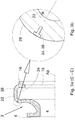
- the outer surface 26 of the volute casing 2 is, just after, or downstream of, the wall 28 (being also a part of the volute casing) of the outlet duct 8 provided with at least one blind hole 30 arranged at substantially right angles to the outer surface 26 to extend to a certain depth in the wall 22 of the volute casing 2.
- the blind hole 30 is preferably, but not necessarily, provided with a sensor 32 indicating liquid ingress in the hole 30 from inside the wall 22 of the volute casing 2, i.e. from the interior thereof.
- Figure 1c shows a second similar blind hole 30' - sensor 32' pair arranged somewhat upstream of the first one such that the blind hole is positioned at the root of the outlet duct 8.
- a third blind hole 30" - sensor 32" pair is arranged to extend deep into the cutwater tongue 20.
- a fourth blind hole 30'" - sensor 32'" pair is arranged in the wall 28 of the outlet duct 8 for monitoring the wear of the wall of the outlet duct downstream of the cutwater tongue.
- the blind holes 30, 30', 30" and 30'" are arranged to positions where the abrasive action of the liquid to be pumped is the highest. Extensive performed tests have shown that the position of maximal abrasive stress is the highest where the distance D of the inner surface 24 of the volute casing 2 from the axis A P in the axial plane (see Fig.
- centrifugal pump 2a is the longest and resulting in the flow velocity of the fluid being the highest, whereby the centrifugal force pressing the abrasive particles against the inner surface 24 of the volute casing is the highest, too.
- a position is the one shown in Figures 1c , 2a and 2b , i.e. close to the cutwater tongue and in the nearhood of or at the centreline plane C L of the volute casing 2.
- the pumps may have a kind of a double volute with a section having a shorter distance between the two wider volute halves.
- a centrifugal pump may have a, in axial direction, wide volute casing having the distance D of its inner surface growing to an end of the volute casing.
- the cutwater tongue forming a part that divides and separates the fluid into two flows is, due to its shape, position and function, the part that is subjected to the most severe wear.
- the cutwater tongue is provided with the third blind hole 30".
- the hole 30", and the possible sensor 32" positioned therein do not necessarily monitor the condition of the volute casing in view of breakage or the risk of leakage through the wall of the volute casing but the degree of wear of the cutwater tongue.
- the hole 30" may be extended in the cutwater tongue to such a position and depth that, when the wear has reached the hole, the flow conditions at the cutwater tongue are weakened to such a degree that the volute casing should be replaced or serviced until more severe reduction of efficiency is at risk.
- the above discussed and illustrated positions for the blind hole are crucial positions in such pumps that are manufactured of ductile iron or high-tensile steel, like for instance martensitic cast steel ASTM A747 Grade CBCu-2, which allows locally increased stress levels and is, thus, less sensitive to any pressure-related loads.
- One way to make a distinction between ductile/high-tensile and brittle materials is to determine the percentage of elongation after fracture of the metallic material.
- EN ISO 6892-1 specifies the method for tensile testing of metallic materials and defines the mechanical properties which can be determined at room temperature.
- a metallic material whose elongation after fracture is less than 5 may be called brittle, and a material having the elongation after fracture 5 or more is called a ductile or high-tensile material.
- the blind holes 30, 30' and 30'" extend are such that still offers some safety margin until the risk of true leakage through the wall of the volute casing is at hand. I.e. such dimensioning leaves the user sufficient time for arranging the replacement of the worn volute casing with a new one.
- the blind holes may be located such that any leak therefrom is well visible, or the blind holes may be provided with a pipe introducing the leakage to a place where it is easy to detect, or such pipe may be provided with the sensor detecting the presence of liquid.
- the sensor 32 if used, may be a pressure sensor, a conductivity sensor or some other appropriate sensor.
- the holes themselves, there is no specific dimensioning involved.
- the diameter of the holes is, preferably, as small as possible such that the holes do not reduce the strength of the volute casing.
- the hole diameter could be, for instance, 1 tenth of the thickness of the wall of the volute casing or less. The only prerequisite for the hole size is that it has to be able to indicate the leak in a reliable manner whenever it happens.
- Figure 2a illustrates schematically an enlarged view of the axial cross-section of a non-worn or non-abraded volute casing of Figure 1c in accordance with a first preferred embodiment of the present invention, the cross-section being taken along line B - B of Figure 1 c.
- Figure 2a shows how the blind hole 30 and the sensor 32 arranged therein are positioned in the outer surface 26 of the wall 22 of the volute casing in the centreline plane C L of the volute casing.
- the part of the volute casing shown here, i.e. the outer circumference thereof is preferably, but not necessarily, symmetrical to the centreline plane C L .
- Fig. 2a also shows the longest distance D from the inner surface 24 of the volute casing to the axis A P thereof.
- Figure 2b illustrates schematically a view of the volute casing of Figure 2a worn or abraded to such a condition that the blind hole 30 and the sensor 32, if used, are open to the interior of the volute casing.
- the liquid to be pumped, possibly having some abrasive solids entrained therein, circulating along the inner surface 24 of the volute casing has abraded the surface to such a degree that the blind hole 30 has now opened in the inner surface 24' allowing the liquid to enter the hole 30.
- the sensor 32 in the hole sends a signal to the control unit of the pump, which outputs a request to initiate actions for replacing the worn volute casing with a new one, or for servicing the volute casing some other way.
- the highest rate of wear is visible at the centreline plane, as the flow velocity is at its highest at the centreline plane in this kind of a centrifugal pump.
- Figures 3a and 3b illustrate schematically partial axial cross-sectional views of the volute casing in accordance with a second preferred embodiment of the present invention, the cross-sections being taken along an axial plane C - C (running along the axis A p ) of Figure 1b .
- Figure 3c illustrates schematically a partial cross-sectional views of the volute casing, the cross-sections being taken along a plane D - D of Figure 1 b.
- Figure 3a shows the volute casing 2 having an inlet opening 4, an inlet flange 6, an annular rear flange 16, a rear opening 18, and a wall 22 with an inner surface 24 and an outer surface 26.
- the volute casing 2 is made of a hard and brittle material, like for instance cast iron ASTM A532 Class III Type A, in order to better withstand the abrasive action of the liquid to be pumped.
- the elongation after fracture of this kind of a brittle material is less than 5%.
- the blind hole 34 is arranged (possibly, but not necessarily, together with the sensor 36) at substantially right angles to the outer surface 26 of the wall 22 in a position where, in accordance with the performed experiments, the volute casing 2 is subjected to the maximal principal stress.
- FIG. 3c Another position illustrated in Figure 3c where the radius of curvature of the surface of the interior of the volute casing may be very small (resulting in the principal stress being high) is the points where the cutwater tongue 20 joins to the opposite walls 22, or actually to the side walls 22' of the volute casing.
- Such points have been provided in Figure 3c with blind holes 34' corresponding in their depth, dimension and use to the blind holes 30 ... 30'" and 34 of the earlier drawings.
- the blind holes 34' arranged to such positions extend to such a depth that still offers some safety margin until the risk of breaking of the volute casing is at hand. I.e. such dimensioning leaves the user sufficient time for arranging the replacement of the worn volute casing with a new one or servicing the volute casing in an appropriate manner.
- Figure 3c shows the blind hole 34" for monitoring the wear of the cutwater tongue 20 at the centreline plane C L of the volute casing.
- the blind hole 34" may have the same position as the blind hole 30" of Figure 1 c.
- the blind hole 34" is located at a position of the maximal principal stress at the centre of the cutwater tongue 20. It is easy to imagine how the pressure tending to push the side walls 22' of the volute casing apart from one another subjects high tensile stresses to both the side corners of the cutwater tongue and at the centre thereof.
- the depth of the blind holes above and the safety margins discussed in conjunction therewith are, preferably, defined such that the one who receives the information from the sensor has sufficient time to acquire the volute casing and the service personnel to perform the replacement of the volute casing.
- the safety margin may, for instance, mean that the volute casing does not collapse or start to leak until after a week or a month after the alarm, whatever type such may be.
- the monitoring arrangement may be programmed to give an estimate of the remaining working days of the volute casing.
- the use of the above described monitoring arrangement provided with sensors offers various alternatives for performing the condition monitoring of a centrifugal pump.
- the information from the sensors may be forwarded to at least one of a local (nearby the pump) control room, a centralized control room of the industrial facility the pump is installed in, a centralized spare parts storage of a company and the warehouse of the pump manufacturer, just to name a few options.
- the information provided by the sensors may be in the form of at least one of a warning light, an audible alarm, an automated message to service personnel and a pre-programmed order for a new volute casing,
Landscapes
- Engineering & Computer Science (AREA)
- Mechanical Engineering (AREA)
- General Engineering & Computer Science (AREA)
- Physics & Mathematics (AREA)
- General Physics & Mathematics (AREA)
- Structures Of Non-Positive Displacement Pumps (AREA)
Abstract
Description
- The present invention relates to a method of and an arrangement for monitoring the condition of a volute casing of a centrifugal pump in accordance with the preambles of the independent claims. More specifically the present invention relates to monitoring the wear of the volute casing of a centrifugal pump.
- As long as centrifugal pumps have been used the components of the pump, mostly the impeller and the volute casing thereof have worn or been abraded. The degree or rate of wear or abrasion has been the higher the more abrasive material the liquid to be pumped has contained and/or the weaker the material the components have been made of has been.
- The wear of the impeller appears as a decrease in the performance of the pump, i.e. both the head and the efficiency of the pump drops resulting in the increase in the energy consumption of the pump. Thus by monitoring the specific energy consumption of the pump the condition of the impeller may be kept an eye on.
- The wear of the volute casing affects the performance of the pump but normally less than the impeller wear. Traditionally, the wear of the volute casing has been observed only visually as the pump starts to leak, i.e. a small jet or spray of liquid exits the volute casing. In case the leak or jet cannot be readily observed due to other equipment hiding the pump, a small pond of liquid may be seen below or at a side of the pump indicating wear in the volute casing. As such an open leak is seldom, if ever, a desired feature, different ways to detect the beginning leak have been searched for.
-
US-B2-9,062,682 - Such sensors may operate in a reliable manner in cases where the wear causes some kind of imbalance, like for instance a broken impeller vane does. However, in a case where the wear is based on, for instance, abrasive matter rotating in the volute casing resulting in even wear all over the circumference of the volute casing the wear does not result in unsteady pressures or acoustic emissions until the wear has found its way through the thinnest part of the volute casing. However, such is too late, as the aim should be towards precautionary wear monitoring whereby the service of the volute casing may be timed to take place during customary service outages instead of sudden breakage of the volute casing causing an interruption in the normal production for the period of volute replacement.
- An object of the present invention is to provide such a novel method of and an arrangement for monitoring the wear of a volute casing of a centrifugal pump that overcomes at least some problems of prior art arrangements.
- Another object of the present invention is to provide such a novel method of and an arrangement for monitoring the wear of a volute casing of a centrifugal pump that takes into account different types of wear of a centrifugal pump.
- Thus one object of the present invention is to provide such a novel method of and an arrangement for monitoring the wear of a volute casing of a centrifugal pump that is specifically aimed at cases where avoiding the leakage caused by local wear is the main concern.
- Thus another object of the present invention is to provide such a novel method of and an arrangement for monitoring the wear of a volute casing of a centrifugal pump that is specifically aimed at cases where avoiding the collapse of the strength of the volute casing is the main concern.
- Yet another object of the present invention is to provide such a novel method of and an arrangement for monitoring the wear of a volute casing of a centrifugal pump that takes into account different materials the volute casing is made of.
- A further object of the present invention is to provide a novel method and an arrangement for monitoring the wear of a volute casing of a centrifugal pump that is made of hard and brittle material.
- A still further object of the present invention is to provide a novel arrangement for monitoring the wear of a volute casing of a centrifugal pump that is made of ductile or high-tensile material.
- The objects of the invention can be met substantially as is disclosed in the independent claims and in the other claims describing more details of different embodiments of the present invention.
- According to an embodiment of the present invention a method of monitoring the condition of a volute casing of a centrifugal pump, the volute casing comprising an outlet duct with a wall and an outlet opening; a centreline plane CL; a cutwater tongue; an axis AP; and a wall having an inner surface defining an interior of the volute casing and an outer surface, comprises the steps of:
- a) determining, in the wall of the volute casing, at least one point, which, in view of the material the volute casing is made of, is critical to wear,
- b) providing, from outside the volute casing, a blind hole in the wall of the volute casing at said at least one point, the blind hole having a depth,
- c) receiving information from the blind hole, and
- d) taking predetermined actions to replace the volute casing with a new one after the information having indicated the opening of the blind hole into the interior of the volute casing.
- This provides a volute casing for a centrifugal pump the performance and reliability of which are considerably improved.
- According to an embodiment of the present invention an arrangement for monitoring the condition of a volute casing of a centrifugal pump, the pump having a volute casing, the volute casing comprising an outlet duct, an outlet opening, a centreline plane CL running at right angles to the axis AP via , an axis AP, and a wall having and inner surface defining the interior of the volute casing and an outer surface, comprises at least one blind hole arranged to extend in a depth in the outer surface of the wall of the volute casing.
- The exemplary embodiments of the present invention discussed in this patent application are not to be interpreted to pose limitations to the applicability of the appended claims. The verb "to comprise" is used in this patent application as an open limitation that does not exclude the existence of also non-recited features. The features recited in dependent claims are mutually freely combinable unless otherwise explicitly stated. The novel features, which are considered as characteristic of the present invention, are set forth in particular in the appended claims.
- In the following, the method of and the arrangement for monitoring the condition of a volute casing of a centrifugal pump of the present invention will be discussed in more detail with reference to the accompanying exemplary, schematic drawings, in which
-
Figure 1a illustrates a side view of a volute casing of a centrifugal pump, -
Figure 1b illustrates a radial cross-sectional view of the volute casing ofFigure1 a , the cross-section being taken along the centreline plane of the volute casing running at right angles to the pump axis, i.e. along line A - A ofFigure 1 a, -
Figure 1 c illustrates an enlarged partial view of the volute casing ofFigure 1b in accordance with a first preferred embodiment of the present invention, -
Figure 2a illustrates an axial cross-sectional view of a non-worn or non-abraded volute casing along line B - B ofFigure 1c , and -
Figure 2b illustrates an axial cross-sectional view of the volute casing ofFigure 2a worn or abraded to such a degree that the sensor is open to the inside of the volute casing, -
Figure 3a illustrates a partial axial cross-section of a volute casing ofFigure 1a in accordance with a second preferred embodiment of the present invention, the cross-section being taken along line C - C ofFigure 1 , -
Figure 3b illustrates an enlarged and partial view of the axial cross-section ofFigure 3a and -
Figure 3c illustrates a partial cross-section of a volute casing ofFigure 1a in accordance with a second preferred embodiment of the present invention, the cross-section being taken along line D - D ofFigure 1 . -
Figure 1a illustrates a side view of avolute casing 2 of a centrifugal pump andFigure 1b illustrates schematically a cross-sectional view of the volute casing ofFigure 1 a along line A - A. Thevolute casing 2 inFigure 1b is shown as a cross-section viewed from the direction of the inlet opening 4 of thevolute casing 2 and taken along a radial centreline plane CL running at right angles to the pump axis AP. Thevolute casing 2 has an inlet opening 4 with aninlet flange 6, anoutlet duct 8 with an outlet opening 10 surrounded by anoutlet flange 12, a support structure, i.e. afoot 14, and anannular flange 16 surrounding an opening 18 via which the impeller of the centrifugal pump may be installed within thevolute casing 2. Thevolute casing 2 has also an axis AP, which coincides with the axis of the shaft of the centrifugal pump when the shaft, the impeller, the volute casing, the bearings and the sealings are assembled to form a centrifugal pump. The inlet opening 4, theinlet flange 6, theannular rearflange 16 and therear opening 18 therein are positioned concentrically with the axis AP. The volute casing has a centreline plane CL (often being common with that of the outlet opening 10 and the outlet flange 12) running usually, but not necessarily, at right angles to the axis AP via the centre of the outlet opening 10. The curved, usually spiral, line formed when the centreline plane CL crosses the inner wall of thevolute casing 2 defines the part of thevolute casing 2 usually farthest from the axis AP of the volute casing 2 (i.e. having the longest distance), whereby the flow velocity of the fluid circulating in thevolute casing 2 is at its highest at or near the curved line. Thevolute casing 2 has further acutwater tongue 20, which separates a part of the liquid to be pumped at the throat of the volute casing to theoutlet duct 8 the rest of the liquid continuing its circulation within thevolute casing 2, i.e. in the interior thereof. -
Figure 1c illustrates schematically a partial enlarged view of the volute casing ofFigure 1b in accordance with a first preferred embodiment of the present invention.Figure 1c thus illustrates the part of thevolute casing 2 comprising thecutwater tongue 20 and a part downstream thereof. The word 'downstream' refers to the direction of liquid flow circulating in thevolute casing 2 past thecutwater tongue 20. Thevolute casing 2 has awall 22 with aninner surface 24 defining the interior of the volute casing and along which the liquid to be pumped flows, and anouter surface 26 in communication with ambient air. Theouter surface 26 of thevolute casing 2 is, just after, or downstream of, the wall 28 (being also a part of the volute casing) of theoutlet duct 8 provided with at least oneblind hole 30 arranged at substantially right angles to theouter surface 26 to extend to a certain depth in thewall 22 of thevolute casing 2. Theblind hole 30 is preferably, but not necessarily, provided with asensor 32 indicating liquid ingress in thehole 30 from inside thewall 22 of thevolute casing 2, i.e. from the interior thereof.Figure 1c shows a second similar blind hole 30' - sensor 32' pair arranged somewhat upstream of the first one such that the blind hole is positioned at the root of theoutlet duct 8. A thirdblind hole 30" -sensor 32" pair is arranged to extend deep into thecutwater tongue 20. And a fourth blind hole 30'" - sensor 32'" pair is arranged in thewall 28 of theoutlet duct 8 for monitoring the wear of the wall of the outlet duct downstream of the cutwater tongue. Theblind holes inner surface 24 of thevolute casing 2 from the axis AP in the axial plane (seeFig. 2a ) is the longest and resulting in the flow velocity of the fluid being the highest, whereby the centrifugal force pressing the abrasive particles against theinner surface 24 of the volute casing is the highest, too. In ordinary centrifugal pumps such a position is the one shown inFigures 1c ,2a and 2b , i.e. close to the cutwater tongue and in the nearhood of or at the centreline plane CL of thevolute casing 2. However, there are centrifugal pumps where the longest distance D is at a side of the centreline plane CL, i.e. the pumps may have a kind of a double volute with a section having a shorter distance between the two wider volute halves. Or a centrifugal pump may have a, in axial direction, wide volute casing having the distance D of its inner surface growing to an end of the volute casing. - The cutwater tongue forming a part that divides and separates the fluid into two flows is, due to its shape, position and function, the part that is subjected to the most severe wear. As the wear of the cutwater tongue has a significant influence on the efficiency of the centrifugal pump, the cutwater tongue is provided with the third
blind hole 30". In other words, thehole 30", and thepossible sensor 32" positioned therein, do not necessarily monitor the condition of the volute casing in view of breakage or the risk of leakage through the wall of the volute casing but the degree of wear of the cutwater tongue. Thehole 30" may be extended in the cutwater tongue to such a position and depth that, when the wear has reached the hole, the flow conditions at the cutwater tongue are weakened to such a degree that the volute casing should be replaced or serviced until more severe reduction of efficiency is at risk. The above discussed and illustrated positions for the blind hole are crucial positions in such pumps that are manufactured of ductile iron or high-tensile steel, like for instance martensitic cast steel ASTM A747 Grade CBCu-2, which allows locally increased stress levels and is, thus, less sensitive to any pressure-related loads. One way to make a distinction between ductile/high-tensile and brittle materials is to determine the percentage of elongation after fracture of the metallic material. EN ISO 6892-1 specifies the method for tensile testing of metallic materials and defines the mechanical properties which can be determined at room temperature. A metallic material whose elongation after fracture is less than 5 may be called brittle, and a material having the elongation after fracture 5 or more is called a ductile or high-tensile material. - However, as such ductile irons or high tensile steels are not especially hard they are sensitive to abrasion. The depth in which the
blind holes 30, 30' and 30'" extend is such that still offers some safety margin until the risk of true leakage through the wall of the volute casing is at hand. I.e. such dimensioning leaves the user sufficient time for arranging the replacement of the worn volute casing with a new one. Naturally, the blind holes may be located such that any leak therefrom is well visible, or the blind holes may be provided with a pipe introducing the leakage to a place where it is easy to detect, or such pipe may be provided with the sensor detecting the presence of liquid. Thesensor 32, if used, may be a pressure sensor, a conductivity sensor or some other appropriate sensor. As to the holes themselves, there is no specific dimensioning involved. Naturally, the diameter of the holes is, preferably, as small as possible such that the holes do not reduce the strength of the volute casing. Thus, the hole diameter could be, for instance, 1 tenth of the thickness of the wall of the volute casing or less. The only prerequisite for the hole size is that it has to be able to indicate the leak in a reliable manner whenever it happens. -
Figure 2a illustrates schematically an enlarged view of the axial cross-section of a non-worn or non-abraded volute casing ofFigure 1c in accordance with a first preferred embodiment of the present invention, the cross-section being taken along line B - B ofFigure 1 c.Figure 2a shows how theblind hole 30 and thesensor 32 arranged therein are positioned in theouter surface 26 of thewall 22 of the volute casing in the centreline plane CL of the volute casing. The part of the volute casing shown here, i.e. the outer circumference thereof is preferably, but not necessarily, symmetrical to the centreline plane CL.Fig. 2a also shows the longest distance D from theinner surface 24 of the volute casing to the axis AP thereof. -
Figure 2b illustrates schematically a view of the volute casing ofFigure 2a worn or abraded to such a condition that theblind hole 30 and thesensor 32, if used, are open to the interior of the volute casing. In other words, the liquid to be pumped, possibly having some abrasive solids entrained therein, circulating along theinner surface 24 of the volute casing has abraded the surface to such a degree that theblind hole 30 has now opened in the inner surface 24' allowing the liquid to enter thehole 30. Thesensor 32 in the hole sends a signal to the control unit of the pump, which outputs a request to initiate actions for replacing the worn volute casing with a new one, or for servicing the volute casing some other way. Here, as expected, the highest rate of wear is visible at the centreline plane, as the flow velocity is at its highest at the centreline plane in this kind of a centrifugal pump. -
Figures 3a and 3b illustrate schematically partial axial cross-sectional views of the volute casing in accordance with a second preferred embodiment of the present invention, the cross-sections being taken along an axial plane C - C (running along the axis Ap) ofFigure 1b .Figure 3c illustrates schematically a partial cross-sectional views of the volute casing, the cross-sections being taken along a plane D - D ofFigure 1 b.Figure 3a shows thevolute casing 2 having aninlet opening 4, aninlet flange 6, an annularrear flange 16, arear opening 18, and awall 22 with aninner surface 24 and anouter surface 26. In this embodiment thevolute casing 2 is made of a hard and brittle material, like for instance cast iron ASTM A532 Class III Type A, in order to better withstand the abrasive action of the liquid to be pumped. The elongation after fracture of this kind of a brittle material is less than 5%. Thus, such a material endures only a very limited amount of elongation (if any) due to the pressure load-induced deformations. Therefore, theblind hole 34 is arranged (possibly, but not necessarily, together with the sensor 36) at substantially right angles to theouter surface 26 of thewall 22 in a position where, in accordance with the performed experiments, thevolute casing 2 is subjected to the maximal principal stress. The highest principal stresses are usually found in positions where the radius R of curvature of theinner surface 24 of the volute casing in the shown axial cross section is the smallest. One such position is found in the "corners" of thevolute casing 2 where the pressure acting on theinner surface 24 tends to bend the volute casing to increase its radius of curvature in an axial plane. As the same phenomenon takes place over the entire circumference of the volute casing, more than 2, preferably 4 to 12, more preferably 6 - 8 sensors should be located to the circumference of the volute casing at equal intervals. Another position illustrated inFigure 3c where the radius of curvature of the surface of the interior of the volute casing may be very small (resulting in the principal stress being high) is the points where thecutwater tongue 20 joins to theopposite walls 22, or actually to the side walls 22' of the volute casing. Such points have been provided inFigure 3c with blind holes 34' corresponding in their depth, dimension and use to theblind holes 30 ... 30'" and 34 of the earlier drawings. The blind holes 34' arranged to such positions extend to such a depth that still offers some safety margin until the risk of breaking of the volute casing is at hand. I.e. such dimensioning leaves the user sufficient time for arranging the replacement of the worn volute casing with a new one or servicing the volute casing in an appropriate manner.Figure 3c shows theblind hole 34" for monitoring the wear of thecutwater tongue 20 at the centreline plane CL of the volute casing. Theblind hole 34" may have the same position as theblind hole 30" ofFigure 1 c. When brittle material is in question, theblind hole 34" is located at a position of the maximal principal stress at the centre of thecutwater tongue 20. It is easy to imagine how the pressure tending to push the side walls 22' of the volute casing apart from one another subjects high tensile stresses to both the side corners of the cutwater tongue and at the centre thereof. - The depth of the blind holes above and the safety margins discussed in conjunction therewith are, preferably, defined such that the one who receives the information from the sensor has sufficient time to acquire the volute casing and the service personnel to perform the replacement of the volute casing. Thus, the safety margin may, for instance, mean that the volute casing does not collapse or start to leak until after a week or a month after the alarm, whatever type such may be. Also, based on the rate of wear from the installation of the volute casing to the alarm, the monitoring arrangement may be programmed to give an estimate of the remaining working days of the volute casing.
- The use of the above described monitoring arrangement provided with sensors offers various alternatives for performing the condition monitoring of a centrifugal pump. The information from the sensors may be forwarded to at least one of a local (nearby the pump) control room, a centralized control room of the industrial facility the pump is installed in, a centralized spare parts storage of a company and the warehouse of the pump manufacturer, just to name a few options. The information provided by the sensors may be in the form of at least one of a warning light, an audible alarm, an automated message to service personnel and a pre-programmed order for a new volute casing,
- While the invention has been described herein by way of examples in connection with what are, at present, considered to be the most preferred embodiments, it is to be understood that the invention is not limited to the disclosed embodiments, but is intended to cover various combinations or modifications of its features, and several other applications included within the scope of the invention, as defined in the appended claims. The details mentioned in connection with any embodiment above may be used in connection with another embodiment when such combination is technically feasible.
Claims (20)
- A method of monitoring the condition of a volute casing of a centrifugal pump, the volute casing (2) comprising an outlet duct (8) with a wall (28) and an outlet opening (10); a centreline plane (CL); a cutwater tongue (20); an axis (AP); and a wall (22) having an inner surface (24) defining an interior of the volute casing (2) and an outer surface (26), the method being characterized by the steps ofa) determining, in the wall (22,28) of the volute casing (2), at least one point, which, in view of the material the volute casing is made of, is critical to wear,b) providing, from outside the volute casing, a blind hole (30, 30', 30", 30"', 34, 34', 34") in the wall (22, 28) of the volute casing (2) at said at least one point, the blind hole (30, 30', 30", 30"', 34, 34', 34") having a depth,c) receiving information from the blind hole (30, 30', 30", 30"', 34, 34', 34"), andd) taking predetermined actions to replace the volute casing (2) with a new one after the information having indicated the opening of the blind hole (30, 30', 30", 30"', 34, 34', 34") into the interior of the volute casing (2).
- The method as recited in claim 1, characterized by, in step a), determining the at least one point for a pump made of a high-tensile steel or ductile iron to such a position in the volute casing (2) that has, in the axial cross section of the volute casing, the longest distance D from the axis AP, i.e. a position where the volute casing (2) is subjected to maximal abrasive load.
- The method as recited in claim 1 or 2, characterized by, in step b), positioning the blind hole (30, 30', 30", 30"', 34', 34") in the wall (22, 28) of the volute casing (2) in close proximity of the cutwater tongue (20).
- The method as recited in claim 1, characterized by, in step a), determining the at least one point for a pump made of a hard and brittle cast iron, to at such a position in the volute casing (2) that the radius R of the inner surface (24) of the volute casing (2), in an axial cross section, is at its smallest, i.e. a position where the volute casing is subjected to maximal principal stress, and in step b), providing, from outside the volute casing, a blind hole (34) in the wall (22, 28) of the volute casing (2) at said at least one point.
- The method as recited in claim 1, characterized by, in step a), determining the at least one point for a pump made of a hard and brittle cast iron to such a position that the cutwater tongue (20) joins to the side wall (22') of the volute casing (2), and in step b), providing, from outside the volute casing, a blind hole (34') in the wall (22) of the volute casing (2) at said at least one point.
- The method as recited in claim 1, characterized by, in step a), determining the at least one point for a pump made of a hard and brittle cast iron in the cutwater tongue (20) at the centreline plane CL of the volute casing (2), and in step b), providing, from outside the volute casing, a blind hole (34") in the cutwater tongue (20) of the volute casing (2) at said at least one point.
- The method as recited in claim 1, characterized by, in step b), determining the depth of the blind hole (30, 30', 30"', 34, 34', 34") to correspond to the smallest safe thickness of the wall (22) of the volute casing (2) in relation to either the strength requirements or the resistance to wear of the volute casing (2) in said point.
- The method as recited in claim 1, characterized by, in step b), determining the depth of the blind hole (30") to correspond to the smallest usable thickness of the wall (22) of the volute casing in view of the flow conditions at the cutwater tongue (20).
- The method as recited in claim 1, characterized by, between steps b) and c), arranging a sensor (32, 32', 32", 32"', 36) in communication with the blind hole (30, 30', 30", 30"', 34, 34', 34") for sending a signal when the blind hole (30, 30', 30", 30"', 34, 34', 34") has opened to the interior of the volute casing (2).
- The method as recited in claim 1, characterized by, in step c), receiving visual information from the blind hole (30, 30', 30", 30"', 34, 34', 34") or a signal from a sensor (32, 32', 32", 32"', 36) provided in communication with the blind hole (30, 30', 30", 30"', 34, 34', 34").
- An arrangement for monitoring the condition of a volute casing of a centrifugal pump, the pump having a volute casing (2), the volute casing (2) comprising an outlet duct (8), an outlet opening (10), a centreline plane (CL) running at right angles to the axis (AP) via , an axis (AP), and a wall (22) having and inner surface (24) defining the interior of the volute casing (2) and an outer surface (26), characterized in at least one blind hole (30, 30', 30", 30"', 34, 34', 34") arranged to extend in a depth in the outer surface (26) of the wall (22) of the volute casing (2).
- The arrangement as recited in claim 11, characterized in that the at least one blind hole (34, 34') is arranged to a position where the principal stress subjected to the volute casing (2) is maximal.
- The arrangement as recited in claim 11, characterized in that the at least one blind hole (30, 30', 30"') is arranged to a position where the abrasion subjected to the volute casing (2) is maximal.
- The arrangement as recited in claim 13, characterized in that the at least one blind hole (30, 30', 30"') is arranged in the volute casing (2) to such a position that has, in the axial cross section of the volute casing, the longest distance D from the axis AP.
- An arrangement as recited in claim 11, characterized in that the depth of the blind hole (30") is arranged to correspond to the smallest usable thickness of the wall (22) of the volute casing in view of the flow conditions at the cutwater tongue (20).
- An arrangement as recited in claim 11, characterized in that the at least one blind hole (34, 34') is arranged to a position where the radius R of curvature of the inner surface (24) of the wall (22) of the volute casing (2) in an axial cross section of the volute casing is at its smallest.
- An arrangement as recited in claim 11, characterized in that the at least one blind hole (34") is arranged to the cutwater tongue (20) at the centreline plane CL of the volute casing (2).
- An arrangement as recited in claim 16, characterized in several blind holes (34) arranged to the entire circumference of the volute casing (2).
- An arrangement as recited in any one of the claims 11 - 18, characterized in a sensor (32, 32', 32", 32"', 36) provided in communication with at least one blind hole (30, 30', 30", 30"', 34, 34', 34").
- An arrangement as recited in claim 19, characterized in that the sensor (32, 32', 32", 32"', 36) is one of a pressure sensor and a conductivity sensor.
Priority Applications (5)
| Application Number | Priority Date | Filing Date | Title |
|---|---|---|---|
| EP16195981.2A EP3315783B1 (en) | 2016-10-27 | 2016-10-27 | A method of and an arrangement for monitoring the condition of a volute casing of a centrifugal pump |
| US15/720,893 US10480517B2 (en) | 2016-10-27 | 2017-09-29 | Method of and arrangement for monitoring the condition of a volute casing of a centrifugal pump |
| RU2017134119A RU2739933C2 (en) | 2016-10-27 | 2017-10-03 | Method and design for centrifugal pump spiral casing condition monitoring |
| BR102017021392-7A BR102017021392B1 (en) | 2016-10-27 | 2017-10-05 | METHOD AND ARRANGEMENT FOR MONITORING THE CONDITION OF A VOLUTE CASING OF A CENTRIFUGAL PUMP |
| CN201710954317.2A CN108005955B (en) | 2016-10-27 | 2017-10-13 | Method and arrangement for monitoring the condition of the volute of a centrifugal pump |
Applications Claiming Priority (1)
| Application Number | Priority Date | Filing Date | Title |
|---|---|---|---|
| EP16195981.2A EP3315783B1 (en) | 2016-10-27 | 2016-10-27 | A method of and an arrangement for monitoring the condition of a volute casing of a centrifugal pump |
Publications (2)
| Publication Number | Publication Date |
|---|---|
| EP3315783A1 true EP3315783A1 (en) | 2018-05-02 |
| EP3315783B1 EP3315783B1 (en) | 2021-09-29 |
Family
ID=57208211
Family Applications (1)
| Application Number | Title | Priority Date | Filing Date |
|---|---|---|---|
| EP16195981.2A Active EP3315783B1 (en) | 2016-10-27 | 2016-10-27 | A method of and an arrangement for monitoring the condition of a volute casing of a centrifugal pump |
Country Status (4)
| Country | Link |
|---|---|
| US (1) | US10480517B2 (en) |
| EP (1) | EP3315783B1 (en) |
| CN (1) | CN108005955B (en) |
| RU (1) | RU2739933C2 (en) |
Citations (4)
| Publication number | Priority date | Publication date | Assignee | Title |
|---|---|---|---|---|
| DE19647967A1 (en) * | 1996-11-20 | 1998-05-28 | Wilo Gmbh | Pump esp. motor driven centrifugal pump with sensor determining pressure differences |
| EP2626567A1 (en) * | 2012-02-08 | 2013-08-14 | Grundfos Holding A/S | Pump casing |
| US20130243578A1 (en) * | 2010-11-29 | 2013-09-19 | Gp Enterprises Co., Ltd. | Pipeline Pump with Thermal Protection |
| US9062682B2 (en) | 2008-05-20 | 2015-06-23 | Cidra Corporate Services Inc. | Applications of pump performance monitoring |
Family Cites Families (11)
| Publication number | Priority date | Publication date | Assignee | Title |
|---|---|---|---|---|
| SU418635A1 (en) * | 1972-09-05 | 1974-03-05 | ||
| US4442707A (en) * | 1982-12-20 | 1984-04-17 | Allis-Chalmers Corporation | Method and centrifugal apparatus for slurry erosion testing |
| JPH0197810A (en) * | 1987-10-09 | 1989-04-17 | Hitachi Ltd | Detecting method of wear of hydraulic machine due to earth and sand |
| JP2000097192A (en) * | 1998-09-21 | 2000-04-04 | Yoshitani Kikai Seisakusho:Kk | Seal box for pump |
| JP4792930B2 (en) * | 2005-11-16 | 2011-10-12 | 株式会社日立プラントテクノロジー | Double suction centrifugal pump pressure resistance test equipment |
| US7871241B2 (en) * | 2008-01-15 | 2011-01-18 | Weir Slurry Group, Inc. | Self-monitoring system for evaluating and controlling adjustment requirements of leakage restricting devices in rotodynamic pumps |
| RU2382907C1 (en) * | 2008-08-18 | 2010-02-27 | Станислав Викторович Попов | Deep-well pump for abrasive-containing, aggressive and infammable liquids |
| FR2981131B1 (en) * | 2011-10-07 | 2013-11-01 | Turbomeca | CENTRIFUGAL COMPRESSOR EQUIPPED WITH A WEAR MEASUREMENT MARKER AND WEAR FOLLOWING METHOD USING THE MARKER |
| CN204386904U (en) * | 2014-12-02 | 2015-06-10 | 江苏大学 | A kind of mechanical shield pump bearing gauge wear real-time monitoring device |
| AU2017205172B2 (en) * | 2016-01-06 | 2022-02-10 | Bivacor Inc. | Heart pump |
| CN106151053B (en) * | 2016-08-23 | 2019-01-25 | 杭州大路实业有限公司 | A kind of lined oil-slurry pump and its assembly and liner wear monitoring method |
-
2016
- 2016-10-27 EP EP16195981.2A patent/EP3315783B1/en active Active
-
2017
- 2017-09-29 US US15/720,893 patent/US10480517B2/en active Active
- 2017-10-03 RU RU2017134119A patent/RU2739933C2/en active
- 2017-10-13 CN CN201710954317.2A patent/CN108005955B/en active Active
Patent Citations (4)
| Publication number | Priority date | Publication date | Assignee | Title |
|---|---|---|---|---|
| DE19647967A1 (en) * | 1996-11-20 | 1998-05-28 | Wilo Gmbh | Pump esp. motor driven centrifugal pump with sensor determining pressure differences |
| US9062682B2 (en) | 2008-05-20 | 2015-06-23 | Cidra Corporate Services Inc. | Applications of pump performance monitoring |
| US20130243578A1 (en) * | 2010-11-29 | 2013-09-19 | Gp Enterprises Co., Ltd. | Pipeline Pump with Thermal Protection |
| EP2626567A1 (en) * | 2012-02-08 | 2013-08-14 | Grundfos Holding A/S | Pump casing |
Also Published As
| Publication number | Publication date |
|---|---|
| CN108005955A (en) | 2018-05-08 |
| US20180119700A1 (en) | 2018-05-03 |
| RU2017134119A3 (en) | 2020-11-23 |
| RU2017134119A (en) | 2019-04-03 |
| RU2739933C2 (en) | 2020-12-29 |
| BR102017021392A2 (en) | 2018-05-15 |
| EP3315783B1 (en) | 2021-09-29 |
| US10480517B2 (en) | 2019-11-19 |
| CN108005955B (en) | 2021-05-18 |
Similar Documents
| Publication | Publication Date | Title |
|---|---|---|
| US10711802B2 (en) | Pump monitoring | |
| McKee et al. | A review of major centrifugal pump failure modes with application to the water supply and sewerage industries | |
| EP3615809B1 (en) | System and method for monitoring operating condition in a hydraulic turbocharger | |
| KR101639038B1 (en) | Pull-out type vertical pump | |
| WO2013143446A1 (en) | Charging pump for nuclear power plant | |
| Al Thobiani | The non-intrusive detection of incipient cavitation in centrifugal pumps | |
| US10480517B2 (en) | Method of and arrangement for monitoring the condition of a volute casing of a centrifugal pump | |
| US20120282085A1 (en) | Pump Impeller | |
| Chernobrova et al. | Influence of different volute casings theoretical methods design on pump working processes | |
| US11661948B2 (en) | Compressor with vibration sensor | |
| KR101453972B1 (en) | Submersible pump with a spacer | |
| BR102017021392B1 (en) | METHOD AND ARRANGEMENT FOR MONITORING THE CONDITION OF A VOLUTE CASING OF A CENTRIFUGAL PUMP | |
| EP3018360B1 (en) | An intake channel arrangement for a volute casing of a centrifugal pump, a flange member, a volute casing for a centrifugal pump and a centrifugal pump | |
| EP3236080B1 (en) | Rotary machine system | |
| Mostafa et al. | Condition monitoring as a pathway for sustainable operation: a case study for vibration analysis on centrifugal pumps | |
| WO2022075856A1 (en) | Method of preventing damage to a pump | |
| KR101904679B1 (en) | Centrifugal compressor and supercharger with same | |
| JP2015010566A (en) | Centrifugal pump | |
| EP4047186A1 (en) | Gas expander | |
| Yogesh et al. | Reliability improvement of cooling water pump | |
| Hirschberger et al. | A Review Of NSS Limitations: New Opportunities | |
| Bloch | Reliability tips for centrifugal process pumps | |
| Cronin et al. | Design considerations for nonclog pumps | |
| JP2006029228A (en) | Francis type hydraulic machine | |
| Pore et al. | Design and Leak-tightness Analysis of Volute Casing for Axially Split Multistage Centrifugal Pump |
Legal Events
| Date | Code | Title | Description |
|---|---|---|---|
| PUAI | Public reference made under article 153(3) epc to a published international application that has entered the european phase |
Free format text: ORIGINAL CODE: 0009012 |
|
| STAA | Information on the status of an ep patent application or granted ep patent |
Free format text: STATUS: THE APPLICATION HAS BEEN PUBLISHED |
|
| AK | Designated contracting states |
Kind code of ref document: A1 Designated state(s): AL AT BE BG CH CY CZ DE DK EE ES FI FR GB GR HR HU IE IS IT LI LT LU LV MC MK MT NL NO PL PT RO RS SE SI SK SM TR |
|
| AX | Request for extension of the european patent |
Extension state: BA ME |
|
| STAA | Information on the status of an ep patent application or granted ep patent |
Free format text: STATUS: REQUEST FOR EXAMINATION WAS MADE |
|
| 17P | Request for examination filed |
Effective date: 20181102 |
|
| RBV | Designated contracting states (corrected) |
Designated state(s): AL AT BE BG CH CY CZ DE DK EE ES FI FR GB GR HR HU IE IS IT LI LT LU LV MC MK MT NL NO PL PT RO RS SE SI SK SM TR |
|
| RIC1 | Information provided on ipc code assigned before grant |
Ipc: G01M 13/00 20190101ALI20210325BHEP Ipc: F04D 29/42 20060101ALI20210325BHEP Ipc: F04D 15/02 20060101ALI20210325BHEP Ipc: F04D 7/04 20060101AFI20210325BHEP |
|
| GRAP | Despatch of communication of intention to grant a patent |
Free format text: ORIGINAL CODE: EPIDOSNIGR1 |
|
| STAA | Information on the status of an ep patent application or granted ep patent |
Free format text: STATUS: GRANT OF PATENT IS INTENDED |
|
| INTG | Intention to grant announced |
Effective date: 20210511 |
|
| GRAS | Grant fee paid |
Free format text: ORIGINAL CODE: EPIDOSNIGR3 |
|
| GRAA | (expected) grant |
Free format text: ORIGINAL CODE: 0009210 |
|
| STAA | Information on the status of an ep patent application or granted ep patent |
Free format text: STATUS: THE PATENT HAS BEEN GRANTED |
|
| AK | Designated contracting states |
Kind code of ref document: B1 Designated state(s): AL AT BE BG CH CY CZ DE DK EE ES FI FR GB GR HR HU IE IS IT LI LT LU LV MC MK MT NL NO PL PT RO RS SE SI SK SM TR |
|
| REG | Reference to a national code |
Ref country code: GB Ref legal event code: FG4D |
|
| REG | Reference to a national code |
Ref country code: CH Ref legal event code: EP Ref country code: AT Ref legal event code: REF Ref document number: 1434428 Country of ref document: AT Kind code of ref document: T Effective date: 20211015 |
|
| REG | Reference to a national code |
Ref country code: DE Ref legal event code: R096 Ref document number: 602016064253 Country of ref document: DE |
|
| REG | Reference to a national code |
Ref country code: IE Ref legal event code: FG4D |
|
| REG | Reference to a national code |
Ref country code: FI Ref legal event code: FGE |
|
| REG | Reference to a national code |
Ref country code: LT Ref legal event code: MG9D |
|
| REG | Reference to a national code |
Ref country code: SE Ref legal event code: TRGR |
|
| PG25 | Lapsed in a contracting state [announced via postgrant information from national office to epo] |
Ref country code: LT Free format text: LAPSE BECAUSE OF FAILURE TO SUBMIT A TRANSLATION OF THE DESCRIPTION OR TO PAY THE FEE WITHIN THE PRESCRIBED TIME-LIMIT Effective date: 20210929 Ref country code: BG Free format text: LAPSE BECAUSE OF FAILURE TO SUBMIT A TRANSLATION OF THE DESCRIPTION OR TO PAY THE FEE WITHIN THE PRESCRIBED TIME-LIMIT Effective date: 20211229 Ref country code: NO Free format text: LAPSE BECAUSE OF FAILURE TO SUBMIT A TRANSLATION OF THE DESCRIPTION OR TO PAY THE FEE WITHIN THE PRESCRIBED TIME-LIMIT Effective date: 20211229 Ref country code: RS Free format text: LAPSE BECAUSE OF FAILURE TO SUBMIT A TRANSLATION OF THE DESCRIPTION OR TO PAY THE FEE WITHIN THE PRESCRIBED TIME-LIMIT Effective date: 20210929 Ref country code: HR Free format text: LAPSE BECAUSE OF FAILURE TO SUBMIT A TRANSLATION OF THE DESCRIPTION OR TO PAY THE FEE WITHIN THE PRESCRIBED TIME-LIMIT Effective date: 20210929 |
|
| REG | Reference to a national code |
Ref country code: NL Ref legal event code: MP Effective date: 20210929 |
|
| PG25 | Lapsed in a contracting state [announced via postgrant information from national office to epo] |
Ref country code: LV Free format text: LAPSE BECAUSE OF FAILURE TO SUBMIT A TRANSLATION OF THE DESCRIPTION OR TO PAY THE FEE WITHIN THE PRESCRIBED TIME-LIMIT Effective date: 20210929 Ref country code: GR Free format text: LAPSE BECAUSE OF FAILURE TO SUBMIT A TRANSLATION OF THE DESCRIPTION OR TO PAY THE FEE WITHIN THE PRESCRIBED TIME-LIMIT Effective date: 20211230 |
|
| REG | Reference to a national code |
Ref country code: AT Ref legal event code: UEP Ref document number: 1434428 Country of ref document: AT Kind code of ref document: T Effective date: 20210929 |
|
| REG | Reference to a national code |
Ref country code: CH Ref legal event code: PL |
|
| PG25 | Lapsed in a contracting state [announced via postgrant information from national office to epo] |
Ref country code: IS Free format text: LAPSE BECAUSE OF FAILURE TO SUBMIT A TRANSLATION OF THE DESCRIPTION OR TO PAY THE FEE WITHIN THE PRESCRIBED TIME-LIMIT Effective date: 20220129 Ref country code: SK Free format text: LAPSE BECAUSE OF FAILURE TO SUBMIT A TRANSLATION OF THE DESCRIPTION OR TO PAY THE FEE WITHIN THE PRESCRIBED TIME-LIMIT Effective date: 20210929 Ref country code: RO Free format text: LAPSE BECAUSE OF FAILURE TO SUBMIT A TRANSLATION OF THE DESCRIPTION OR TO PAY THE FEE WITHIN THE PRESCRIBED TIME-LIMIT Effective date: 20210929 Ref country code: PT Free format text: LAPSE BECAUSE OF FAILURE TO SUBMIT A TRANSLATION OF THE DESCRIPTION OR TO PAY THE FEE WITHIN THE PRESCRIBED TIME-LIMIT Effective date: 20220131 Ref country code: PL Free format text: LAPSE BECAUSE OF FAILURE TO SUBMIT A TRANSLATION OF THE DESCRIPTION OR TO PAY THE FEE WITHIN THE PRESCRIBED TIME-LIMIT Effective date: 20210929 Ref country code: NL Free format text: LAPSE BECAUSE OF FAILURE TO SUBMIT A TRANSLATION OF THE DESCRIPTION OR TO PAY THE FEE WITHIN THE PRESCRIBED TIME-LIMIT Effective date: 20210929 Ref country code: ES Free format text: LAPSE BECAUSE OF FAILURE TO SUBMIT A TRANSLATION OF THE DESCRIPTION OR TO PAY THE FEE WITHIN THE PRESCRIBED TIME-LIMIT Effective date: 20210929 Ref country code: EE Free format text: LAPSE BECAUSE OF FAILURE TO SUBMIT A TRANSLATION OF THE DESCRIPTION OR TO PAY THE FEE WITHIN THE PRESCRIBED TIME-LIMIT Effective date: 20210929 Ref country code: CZ Free format text: LAPSE BECAUSE OF FAILURE TO SUBMIT A TRANSLATION OF THE DESCRIPTION OR TO PAY THE FEE WITHIN THE PRESCRIBED TIME-LIMIT Effective date: 20210929 Ref country code: AL Free format text: LAPSE BECAUSE OF FAILURE TO SUBMIT A TRANSLATION OF THE DESCRIPTION OR TO PAY THE FEE WITHIN THE PRESCRIBED TIME-LIMIT Effective date: 20210929 |
|
| PG25 | Lapsed in a contracting state [announced via postgrant information from national office to epo] |
Ref country code: MC Free format text: LAPSE BECAUSE OF FAILURE TO SUBMIT A TRANSLATION OF THE DESCRIPTION OR TO PAY THE FEE WITHIN THE PRESCRIBED TIME-LIMIT Effective date: 20210929 |
|
| REG | Reference to a national code |
Ref country code: DE Ref legal event code: R097 Ref document number: 602016064253 Country of ref document: DE |
|
| PG25 | Lapsed in a contracting state [announced via postgrant information from national office to epo] |
Ref country code: LU Free format text: LAPSE BECAUSE OF NON-PAYMENT OF DUE FEES Effective date: 20211027 Ref country code: DK Free format text: LAPSE BECAUSE OF FAILURE TO SUBMIT A TRANSLATION OF THE DESCRIPTION OR TO PAY THE FEE WITHIN THE PRESCRIBED TIME-LIMIT Effective date: 20210929 |
|
| PLBE | No opposition filed within time limit |
Free format text: ORIGINAL CODE: 0009261 |
|
| STAA | Information on the status of an ep patent application or granted ep patent |
Free format text: STATUS: NO OPPOSITION FILED WITHIN TIME LIMIT |
|
| GBPC | Gb: european patent ceased through non-payment of renewal fee |
Effective date: 20211229 |
|
| PG25 | Lapsed in a contracting state [announced via postgrant information from national office to epo] |
Ref country code: LI Free format text: LAPSE BECAUSE OF NON-PAYMENT OF DUE FEES Effective date: 20211031 Ref country code: CH Free format text: LAPSE BECAUSE OF NON-PAYMENT OF DUE FEES Effective date: 20211031 |
|
| 26N | No opposition filed |
Effective date: 20220630 |
|
| PG25 | Lapsed in a contracting state [announced via postgrant information from national office to epo] |
Ref country code: IE Free format text: LAPSE BECAUSE OF NON-PAYMENT OF DUE FEES Effective date: 20211027 Ref country code: GB Free format text: LAPSE BECAUSE OF NON-PAYMENT OF DUE FEES Effective date: 20211229 |
|
| PG25 | Lapsed in a contracting state [announced via postgrant information from national office to epo] |
Ref country code: SI Free format text: LAPSE BECAUSE OF FAILURE TO SUBMIT A TRANSLATION OF THE DESCRIPTION OR TO PAY THE FEE WITHIN THE PRESCRIBED TIME-LIMIT Effective date: 20210929 |
|
| PG25 | Lapsed in a contracting state [announced via postgrant information from national office to epo] |
Ref country code: IT Free format text: LAPSE BECAUSE OF FAILURE TO SUBMIT A TRANSLATION OF THE DESCRIPTION OR TO PAY THE FEE WITHIN THE PRESCRIBED TIME-LIMIT Effective date: 20210929 |
|
| PG25 | Lapsed in a contracting state [announced via postgrant information from national office to epo] |
Ref country code: HU Free format text: LAPSE BECAUSE OF FAILURE TO SUBMIT A TRANSLATION OF THE DESCRIPTION OR TO PAY THE FEE WITHIN THE PRESCRIBED TIME-LIMIT; INVALID AB INITIO Effective date: 20161027 |
|
| P01 | Opt-out of the competence of the unified patent court (upc) registered |
Effective date: 20230412 |
|
| PG25 | Lapsed in a contracting state [announced via postgrant information from national office to epo] |
Ref country code: CY Free format text: LAPSE BECAUSE OF FAILURE TO SUBMIT A TRANSLATION OF THE DESCRIPTION OR TO PAY THE FEE WITHIN THE PRESCRIBED TIME-LIMIT Effective date: 20210929 |
|
| PG25 | Lapsed in a contracting state [announced via postgrant information from national office to epo] |
Ref country code: SM Free format text: LAPSE BECAUSE OF FAILURE TO SUBMIT A TRANSLATION OF THE DESCRIPTION OR TO PAY THE FEE WITHIN THE PRESCRIBED TIME-LIMIT Effective date: 20210929 |
|
| PG25 | Lapsed in a contracting state [announced via postgrant information from national office to epo] |
Ref country code: MK Free format text: LAPSE BECAUSE OF FAILURE TO SUBMIT A TRANSLATION OF THE DESCRIPTION OR TO PAY THE FEE WITHIN THE PRESCRIBED TIME-LIMIT Effective date: 20210929 |
|
| PG25 | Lapsed in a contracting state [announced via postgrant information from national office to epo] |
Ref country code: MT Free format text: LAPSE BECAUSE OF FAILURE TO SUBMIT A TRANSLATION OF THE DESCRIPTION OR TO PAY THE FEE WITHIN THE PRESCRIBED TIME-LIMIT Effective date: 20210929 |
|
| PG25 | Lapsed in a contracting state [announced via postgrant information from national office to epo] |
Ref country code: TR Free format text: LAPSE BECAUSE OF FAILURE TO SUBMIT A TRANSLATION OF THE DESCRIPTION OR TO PAY THE FEE WITHIN THE PRESCRIBED TIME-LIMIT Effective date: 20210929 |
|
| PGFP | Annual fee paid to national office [announced via postgrant information from national office to epo] |
Ref country code: DE Payment date: 20251021 Year of fee payment: 10 |
|
| PGFP | Annual fee paid to national office [announced via postgrant information from national office to epo] |
Ref country code: AT Payment date: 20251022 Year of fee payment: 10 |
|
| PGFP | Annual fee paid to national office [announced via postgrant information from national office to epo] |
Ref country code: FI Payment date: 20251028 Year of fee payment: 10 |
|
| PGFP | Annual fee paid to national office [announced via postgrant information from national office to epo] |
Ref country code: FR Payment date: 20251030 Year of fee payment: 10 |
|
| PGFP | Annual fee paid to national office [announced via postgrant information from national office to epo] |
Ref country code: BE Payment date: 20251021 Year of fee payment: 10 |
|
| PGFP | Annual fee paid to national office [announced via postgrant information from national office to epo] |
Ref country code: SE Payment date: 20251021 Year of fee payment: 10 |