EP3315761A1 - Electromagnetic valve - Google Patents
Electromagnetic valve Download PDFInfo
- Publication number
- EP3315761A1 EP3315761A1 EP16817746.7A EP16817746A EP3315761A1 EP 3315761 A1 EP3315761 A1 EP 3315761A1 EP 16817746 A EP16817746 A EP 16817746A EP 3315761 A1 EP3315761 A1 EP 3315761A1
- Authority
- EP
- European Patent Office
- Prior art keywords
- iron core
- valve
- movable iron
- gap
- valve element
- Prior art date
- Legal status (The legal status is an assumption and is not a legal conclusion. Google has not performed a legal analysis and makes no representation as to the accuracy of the status listed.)
- Granted
Links
Images



Classifications
-
- F—MECHANICAL ENGINEERING; LIGHTING; HEATING; WEAPONS; BLASTING
- F02—COMBUSTION ENGINES; HOT-GAS OR COMBUSTION-PRODUCT ENGINE PLANTS
- F02M—SUPPLYING COMBUSTION ENGINES IN GENERAL WITH COMBUSTIBLE MIXTURES OR CONSTITUENTS THEREOF
- F02M51/00—Fuel-injection apparatus characterised by being operated electrically
- F02M51/06—Injectors peculiar thereto with means directly operating the valve needle
- F02M51/061—Injectors peculiar thereto with means directly operating the valve needle using electromagnetic operating means
- F02M51/0625—Injectors peculiar thereto with means directly operating the valve needle using electromagnetic operating means characterised by arrangement of mobile armatures
- F02M51/0664—Injectors peculiar thereto with means directly operating the valve needle using electromagnetic operating means characterised by arrangement of mobile armatures having a cylindrically or partly cylindrically shaped armature, e.g. entering the winding; having a plate-shaped or undulated armature entering the winding
- F02M51/0685—Injectors peculiar thereto with means directly operating the valve needle using electromagnetic operating means characterised by arrangement of mobile armatures having a cylindrically or partly cylindrically shaped armature, e.g. entering the winding; having a plate-shaped or undulated armature entering the winding the armature and the valve being allowed to move relatively to each other or not being attached to each other
-
- F—MECHANICAL ENGINEERING; LIGHTING; HEATING; WEAPONS; BLASTING
- F02—COMBUSTION ENGINES; HOT-GAS OR COMBUSTION-PRODUCT ENGINE PLANTS
- F02M—SUPPLYING COMBUSTION ENGINES IN GENERAL WITH COMBUSTIBLE MIXTURES OR CONSTITUENTS THEREOF
- F02M63/00—Other fuel-injection apparatus having pertinent characteristics not provided for in groups F02M39/00 - F02M57/00 or F02M67/00; Details, component parts, or accessories of fuel-injection apparatus, not provided for in, or of interest apart from, the apparatus of groups F02M39/00 - F02M61/00 or F02M67/00; Combination of fuel pump with other devices, e.g. lubricating oil pump
- F02M63/0012—Valves
- F02M63/007—Details not provided for in, or of interest apart from, the apparatus of the groups F02M63/0014 - F02M63/0059
- F02M63/0075—Stop members in valves, e.g. plates or disks limiting the movement of armature, valve or spring
-
- F—MECHANICAL ENGINEERING; LIGHTING; HEATING; WEAPONS; BLASTING
- F02—COMBUSTION ENGINES; HOT-GAS OR COMBUSTION-PRODUCT ENGINE PLANTS
- F02M—SUPPLYING COMBUSTION ENGINES IN GENERAL WITH COMBUSTIBLE MIXTURES OR CONSTITUENTS THEREOF
- F02M47/00—Fuel-injection apparatus operated cyclically with fuel-injection valves actuated by fluid pressure
- F02M47/02—Fuel-injection apparatus operated cyclically with fuel-injection valves actuated by fluid pressure of accumulator-injector type, i.e. having fuel pressure of accumulator tending to open, and fuel pressure in other chamber tending to close, injection valves and having means for periodically releasing that closing pressure
- F02M47/027—Electrically actuated valves draining the chamber to release the closing pressure
-
- F—MECHANICAL ENGINEERING; LIGHTING; HEATING; WEAPONS; BLASTING
- F02—COMBUSTION ENGINES; HOT-GAS OR COMBUSTION-PRODUCT ENGINE PLANTS
- F02M—SUPPLYING COMBUSTION ENGINES IN GENERAL WITH COMBUSTIBLE MIXTURES OR CONSTITUENTS THEREOF
- F02M51/00—Fuel-injection apparatus characterised by being operated electrically
- F02M51/06—Injectors peculiar thereto with means directly operating the valve needle
- F02M51/061—Injectors peculiar thereto with means directly operating the valve needle using electromagnetic operating means
- F02M51/0625—Injectors peculiar thereto with means directly operating the valve needle using electromagnetic operating means characterised by arrangement of mobile armatures
- F02M51/0664—Injectors peculiar thereto with means directly operating the valve needle using electromagnetic operating means characterised by arrangement of mobile armatures having a cylindrically or partly cylindrically shaped armature, e.g. entering the winding; having a plate-shaped or undulated armature entering the winding
- F02M51/0671—Injectors peculiar thereto with means directly operating the valve needle using electromagnetic operating means characterised by arrangement of mobile armatures having a cylindrically or partly cylindrically shaped armature, e.g. entering the winding; having a plate-shaped or undulated armature entering the winding the armature having an elongated valve body attached thereto
- F02M51/0675—Injectors peculiar thereto with means directly operating the valve needle using electromagnetic operating means characterised by arrangement of mobile armatures having a cylindrically or partly cylindrically shaped armature, e.g. entering the winding; having a plate-shaped or undulated armature entering the winding the armature having an elongated valve body attached thereto the valve body having cylindrical guiding or metering portions, e.g. with fuel passages
-
- F—MECHANICAL ENGINEERING; LIGHTING; HEATING; WEAPONS; BLASTING
- F02—COMBUSTION ENGINES; HOT-GAS OR COMBUSTION-PRODUCT ENGINE PLANTS
- F02M—SUPPLYING COMBUSTION ENGINES IN GENERAL WITH COMBUSTIBLE MIXTURES OR CONSTITUENTS THEREOF
- F02M63/00—Other fuel-injection apparatus having pertinent characteristics not provided for in groups F02M39/00 - F02M57/00 or F02M67/00; Details, component parts, or accessories of fuel-injection apparatus, not provided for in, or of interest apart from, the apparatus of groups F02M39/00 - F02M61/00 or F02M67/00; Combination of fuel pump with other devices, e.g. lubricating oil pump
- F02M63/0012—Valves
- F02M63/0014—Valves characterised by the valve actuating means
- F02M63/0015—Valves characterised by the valve actuating means electrical, e.g. using solenoid
- F02M63/0017—Valves characterised by the valve actuating means electrical, e.g. using solenoid using electromagnetic operating means
-
- F—MECHANICAL ENGINEERING; LIGHTING; HEATING; WEAPONS; BLASTING
- F16—ENGINEERING ELEMENTS AND UNITS; GENERAL MEASURES FOR PRODUCING AND MAINTAINING EFFECTIVE FUNCTIONING OF MACHINES OR INSTALLATIONS; THERMAL INSULATION IN GENERAL
- F16K—VALVES; TAPS; COCKS; ACTUATING-FLOATS; DEVICES FOR VENTING OR AERATING
- F16K27/00—Construction of housing; Use of materials therefor
- F16K27/02—Construction of housing; Use of materials therefor of lift valves
- F16K27/029—Electromagnetically actuated valves
-
- F—MECHANICAL ENGINEERING; LIGHTING; HEATING; WEAPONS; BLASTING
- F16—ENGINEERING ELEMENTS AND UNITS; GENERAL MEASURES FOR PRODUCING AND MAINTAINING EFFECTIVE FUNCTIONING OF MACHINES OR INSTALLATIONS; THERMAL INSULATION IN GENERAL
- F16K—VALVES; TAPS; COCKS; ACTUATING-FLOATS; DEVICES FOR VENTING OR AERATING
- F16K31/00—Actuating devices; Operating means; Releasing devices
- F16K31/02—Actuating devices; Operating means; Releasing devices electric; magnetic
- F16K31/06—Actuating devices; Operating means; Releasing devices electric; magnetic using a magnet, e.g. diaphragm valves, cutting off by means of a liquid
- F16K31/0675—Electromagnet aspects, e.g. electric supply therefor
-
- F—MECHANICAL ENGINEERING; LIGHTING; HEATING; WEAPONS; BLASTING
- F16—ENGINEERING ELEMENTS AND UNITS; GENERAL MEASURES FOR PRODUCING AND MAINTAINING EFFECTIVE FUNCTIONING OF MACHINES OR INSTALLATIONS; THERMAL INSULATION IN GENERAL
- F16K—VALVES; TAPS; COCKS; ACTUATING-FLOATS; DEVICES FOR VENTING OR AERATING
- F16K31/00—Actuating devices; Operating means; Releasing devices
- F16K31/02—Actuating devices; Operating means; Releasing devices electric; magnetic
- F16K31/06—Actuating devices; Operating means; Releasing devices electric; magnetic using a magnet, e.g. diaphragm valves, cutting off by means of a liquid
- F16K31/0686—Braking, pressure equilibration, shock absorbing
- F16K31/0689—Braking of the valve element
-
- H—ELECTRICITY
- H01—ELECTRIC ELEMENTS
- H01F—MAGNETS; INDUCTANCES; TRANSFORMERS; SELECTION OF MATERIALS FOR THEIR MAGNETIC PROPERTIES
- H01F3/00—Cores, Yokes, or armatures
Definitions
- the present invention relates to a solenoid valve that is used in an internal combustion engine and mainly injects fuel.
- a fuel injection nozzle is provided with a movable stopper that slides with both a movable iron core and a valve element, and forms a gap between the movable iron core and the valve element in a displacement direction in a valve closed state.
- This causes the movable iron core to collide with the valve element when the valve is opened, which enables reduction of a moving time for a distance required to open the injection hole, and allows relative motion between the movable iron core and a valve after opening and closing of the valve, improving controllability of an injection amount.
- a degradation factor of spray atomization is that a fuel flow rate becomes slow in a low lift period at the beginning of opening of a valve element.
- a degradation factor of injection amount stabilization is that convergence of a valve operation is slow after valve opening. Therefore, it is necessary for the fuel injection device to quickly converge the operation of the valve element after valve opening, while making a start of the opening sharp.
- PTL 1 by providing a gap in the displacement direction between the movable iron core and the valve element, only the movable iron core is operated before a start of energization, an impact force at the time of a collision is applied to the valve element upon valve opening, and a low lift engine is shortened. Further, by providing a stopper between the valve elements of the movable iron core, the valve element and the movable iron core can relatively move, enabling stabilization of an injection amount.
- a movable element continues to be displaced downward after valve closing, a speed of the movable element is high in returning to a valve-closed standby state, and a member on an upper part of the valve element is lifted. Accordingly, there has been a problem that, when an injection interval is shortened, the gap in the displacement direction becomes small, and a valve opening behavior is not stabilized.
- the solenoid valve of the present invention includes: a valve element that abuts against and separates from a valve seat to seal fuel; a movable iron core capable of being separated from the valve element; and a fixed iron core arranged opposed to the movable iron core.
- the solenoid valve also includes: a first spring member that energizes the valve element toward a side of the valve seat; a second spring member that energizes the movable iron core toward the fixed iron core; and a stopper part disposed on the side of the valve seat with respect to the movable iron core, and arranged with the movable iron core via a gap in a displacement direction in a valve closed state.
- the gap is set such that the movable iron core collides with the stopper part when being displaced in the valve closing direction after the valve element is opened.
- An object of this embodiment is to provide a structure that improves a stability of an operation of a valve element at valve opening and promotes stabilization of an injection amount even when an injection interval is shortened, in a fuel injection device (solenoid valve) in which the valve element receives an impact force from a movable iron core at the valve opening, and the low lift period at the valve opening can be shortened.
- FIG. 1 is a cross-sectional view showing a structure of the fuel injection device according to an embodiment of the present invention, and is a longitudinal cross-sectional view showing a cut surface parallel to a center axis 100a.
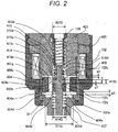
- FIG. 2 is an enlarged cross-sectional view of an electromagnetic drive part 400 shown in FIG. 1 .
- FIG. 3 is a view for describing an operation of a movable portion.
- FIG. 3 (a) shows an ON/OFF state of an injection command pulse
- FIG. 3 (b) shows displacement of a plunger rod 102 and a movable iron core 404 with a valve closed state of the plunger rod 102 as displacement 0.
- the fuel injection device 100 is configured by a fuel supply part 200 that supplies fuel, a nozzle part 300 provided with a valve part 300a at a tip portion to permit or interrupt a flow of the fuel, and the electromagnetic drive part 400 that drives the valve part 300a.
- a fuel supply part 200 that supplies fuel
- a nozzle part 300 provided with a valve part 300a at a tip portion to permit or interrupt a flow of the fuel
- the electromagnetic drive part 400 that drives the valve part 300a.
- an electromagnetic fuel injection device for an internal combustion engine that uses gasoline as fuel will be described as an example.
- the fuel supply part 200, the valve part 300a, the nozzle part 300, and the electromagnetic drive part 400 indicate corresponding portions with respect to the cross section shown in FIG. 1 , and do not indicate a single component.
- the fuel supply part 200 is formed at an upper end side of the figure
- the nozzle part 300 is formed at a lower end side
- the electromagnetic drive part 400 is formed between the fuel supply part 200 and the nozzle part 300. That is, the fuel supply part 200, the electromagnetic drive part 400, and the nozzle part 300 are arranged in this order along a direction of the center axis 100a.
- An end portion of the fuel supply part 200 on an opposite side to the nozzle part 300 is connected to a fuel pipe (not shown).
- An end portion of the nozzle part 300 on an opposite side to the fuel supply part 200 is inserted into a mounting hole (insertion hole) formed in an intake pipe (not shown) or a combustion-chamber forming member (cylinder block, cylinder head, or the like) of the internal combustion engine.
- the electromagnetic fuel injection device 100 receives fuel supply from the fuel pipe through the fuel supply part 200, and injects fuel from the tip portion of the nozzle part 300 into the intake pipe or the combustion chamber.
- a fuel passage 101 (101a to 101f) is formed such that the fuel flows substantially along the center axis 100a direction of the electromagnetic fuel injection device 100.
- the end portion or the end portion side positioned on the opposite side to the nozzle part 300, of the fuel supply part 200 is referred to as a base end portion or a base end side
- the end portion or the end portion side positioned on the opposite side to the fuel supply part 200, of the nozzle part 300 is referred to as a tip portion or a tip side.
- the fuel supply part 200 is configured by a fuel pipe 201.
- One end portion (upper end portion) of the fuel pipe 201 is provided with a fuel supply port 201a, and the fuel passage 101a is formed inside the fuel pipe 201 to penetrate in the direction along the center axis 100a.
- Another end potion (lower end portion) of the fuel pipe 201 is joined to one end portion (upper end portion) of a fixed iron core 401.
- an O-ring 202 and a backup ring 203 are provided on an outer peripheral side of the upper end portion of the fuel pipe 201.
- the O-ring 202 functions as a seal to prevent fuel leakage when the fuel supply port 201a is mounted to the fuel pipe.
- the backup ring 203 is for backing up the O-ring 202.
- the backup ring 203 may be formed by laminating a plurality of ring-shaped members. Inside the fuel supply port 201a, there is disposed a filter 204 that filters foreign matter mixed in the fuel.
- the nozzle part 300 includes a nozzle body 300b, and the valve part 300a is formed at a tip portion (lower end portion) of the nozzle body 300b.
- the nozzle body 300b is a hollow cylindrical body, and forms a fuel passage 101f on an upstream side of the valve part 300a.
- a stopper part 311 is formed in the lower fuel passage portion 101e portion of the electromagnetic drive part 400.
- the valve part 300a includes an injection-hole forming member 301, a guide member 302, and a valve element 303 provided at one end portion (lower end side tip portion) of the plunger rod 102.
- the injection-hole forming member 301 is configured by a valve seat 301a that is in contact with the valve element to seal the fuel, and a fuel injection hole 301b that injects the fuel.
- the injection-hole forming member 301 is inserted and fixed into a recess inner peripheral surface 300ba formed at the tip portion of the nozzle body 300b.
- an outer periphery of a tip end face of the injection-hole forming member 301 and an inner periphery of a tip end face of the nozzle body 300b are welded to seal the fuel.
- the guide part 302 is on an inner peripheral side of the injection-hole forming member 301, and forms a guide surface on the tip end side (lower end side) of the plunger rod 102 to guide a movement of the plunger rod 102 in the direction along the center axis 100a (valve opening/closing direction).
- the electromagnetic drive part 400 is configured by the fixed iron core 401, a coil 402, a housing 403, the movable iron core 404, an intermediate member 414, a plunger cap 410, a first spring member 405, a third spring member 406, and a second spring member 407.
- the fixed iron core 401 is also referred to as a fixed core.
- the movable iron core 404 is also referred to as a movable core, a movable element, or an armature.
- the fixed iron core 401 has the fuel passage 101c in a center portion, and a joint part 401a with the fuel pipe 201.
- An outer peripheral surface 401b of the fixed iron core 401 is fitted and joined to a large diameter inner peripheral portion 300c of the nozzle body 300b, and an outer peripheral surface 401e having a larger diameter than the outer peripheral surface 401b is fitted and joined to an outer-peripheral-side fixed iron core 401d.
- the coil 402 is wound around an outer peripheral side of the fixed iron core 401 and a large diameter portion 300c of the cylindrical member.
- the housing 403 is provided to surround an outer peripheral side of the coil 402, and forms an outer periphery of the electromagnetic fuel injection device 100.
- An upper-end-side inner peripheral surface 403a of the housing 403 is connected to an outer peripheral surface 401f of the outer-peripheral-side fixed iron core 401d joined to the outer peripheral surface 401e of the fixed iron core 401.
- the movable iron core 404 is disposed on a lower end face 401g side of the fixed iron core 401.
- An upper end face 404c of the movable iron core 404 is opposed to a lower end face 401g of the fixed iron core 401 with a gap g2 in a valve closed state.
- the outer peripheral surface of the movable iron core 404 is opposed to the inner peripheral surface of the large diameter portion 300c of the nozzle body 300b via a slight gap, and the movable iron core 404 is provided inside the large diameter portion 300c of the cylindrical member to be movable in the direction along the center axis 100a.
- a magnetic path is formed such that a magnetic flux circulates in the fixed iron core 401, the movable iron core 404, the housing 403, and the large diameter portion 300c of the cylindrical member.
- the movable iron core 404 is attracted in a direction of the fixed iron core 401 by a magnetic attraction force generated by the magnetic flux flowing between the lower end face 401g of the fixed iron core 401 and the upper end face 404c of the movable iron core 404.
- a recessed part 404b recessed from the upper end face 404c side to a lower end face 404a side.
- a fuel passage hole 404d is formed as the fuel passage 101d penetrating to the lower end face 404a side in the direction along the center axis 100a.
- a through hole 404e penetrating to the lower end face 404a side is formed in the direction along the center axis 100a.
- the plunger rod 102 is provided to pass through the through hole 404e.
- the plunger rod 102 is fixed with the plunger cap 410 by fitting, and has a thick diameter part 102a.
- the intermediate member 414 is a cylindrical member having a recessed part serving as a step on inner and outer peripheries, in which an inner peripheral surface 414a abuts against an upper face 102b of the plunger rod thick diameter part 102a, and an outer peripheral surface 414b abuts against the bottom face 404b' of the recess part of the movable iron core. Between a lower face 102c of the thick diameter part and the bottom face 404b' of the movable iron core recessed part 404b, a gap g1 (pre-stroke gap) is provided.
- a length obtained by subtracting height h between the upper face 102b and the lower face 102c of the plunger rod thick diameter part from height 414h of the recessed part step of the intermediate member 414 is the gap g1 described above.
- the stopper part 311 that is a part of the nozzle body 300b and extends from the outer peripheral side of the nozzle body 300b to the inner peripheral side to an inner peripheral side cavity, to a diameter portion 311a.
- An upper end portion of the first spring member 405 abuts against a lower end face of a spring force adjusting member 106, and a lower end portion of the first spring member 405 abuts against an upper spring bearing 410a of the plunger cap 410, to energize the plunger rod 102 downward via the plunger cap 410.
- An upper end portion of the third spring member 406 abuts against a lower spring bearing part 410b of the plunger cap 410, and a lower end portion of the third spring member 406 abuts against an upper face 414c of the intermediate member 414, to energize the intermediate member 414 downward.
- An upper end portion of the second spring 407 abuts against the lower face 404a of the movable iron core 404, and a lower end portion of the second spring 407 abuts against a stepped portion 300d of the nozzle body 300b, to energize the movable iron core 404 upward.
- the coil 402 is wound on a bobbin and assembled to the outer peripheral side of the fixed iron core 401 and the large diameter portion 300b of the cylindrical member, and a resin material is molded around the coil 402.
- a resin material used for this molding a connector 105 having a terminal 104 drawn out from the coil 402 is integrally molded.
- FIG. 2 is an enlarged view of the electromagnetic drive part 400
- FIG. 3 which describes an operation of the movable portion.
- the plunger rod 102 In a valve closed state where the coil 402 is not energized, the plunger rod 102 abuts against the valve seat 301a to close the valve, by a force obtained by subtracting an energizing force of the third spring member 406, from an energizing force of the first spring member 405 energizing the plunger rod 102 in the valve closing direction and the second spring member 407.
- This state is called a valve-closed stationary state.
- the movable iron core 404 abuts against an outer peripheral stepped portion 414b of the intermediate member 414, and is disposed in a valve closing position.
- a gap g2 is provided between the upper end face 404c of the movable iron core 404 and the lower end face 401g of the fixed iron core 401. Between a flat surface 404b' of the recessed part 404b of the movable iron core 404 and the lower face 102c of the plunger rod thick diameter part, the gap g1 is provided. A relationship between g1 and g2 is g2 > g1.
- the gap g3 is set such that only the movable iron core 404 collide with the stopper part 311 when being displaced downward after the opening and closing valve operation of the plunger rod 102.
- the solenoid valve (fuel injection device) of this embodiment includes the valve element 303 that abuts against and separates from the valve seat 301a to seal the fuel, the movable iron core 404 capable of being separated from the valve element 303, and the fixed iron core 401 arranged opposed to the movable iron core 404.
- the first spring member 405 that energizes the valve element 303 toward a side of the valve seat 301a
- the second spring member 407 that energizes the movable iron core 404 toward the fixed iron core 401
- the stopper part 311 disposed on the side of the valve seat 301a with respect to the movable iron core 404, and disposed with the movable iron core 404 via the valve-closed-state gap g3 in a displacement direction in the valve closed state.
- the valve-closed-state gap g3 is set such that the movable iron core 404 collides with the stopper part 311 when being displaced in the valve closing direction after opening of the valve element 303.
- the solenoid valve of this embodiment is arranged with the valve element 303 via the pre-stroke gap g1 in an axial direction in the valve closed state, and provided with the movable iron core 404 that moves in the valve opening direction to axially contact with the valve element 303, and the stopper part 311 disposed on a side of a valve seat part (valve seat 301a) with respect to the movable iron core 404, and arranged in an axial direction with the movable iron core 404 via the valve-closed-state gap g3 in the valve closed state.
- This valve-closed-state gap g3 is set such that the movable iron core 404 collides with the stopper part 311 when returning to the valve closing direction after valve opening, in the solenoid valve.
- a magnetomotive force is generated by the electromagnet formed by the fixed iron core 401, the coil 402, and the housing 403.
- This magnetomotive force causes a flow of a magnetic flux that is formed to surround the coil 402, and circulates the magnetic path formed by the fixed iron core 401, the housing 403, the thick diameter part 300d of the nozzle body, and the movable iron core 404.
- a magnetic attractive force acts between the upper end face 404c of the movable iron core 404 and the lower end face 401g of the fixed iron core 401, and the movable iron core 404 and the intermediate member 414 are displaced toward the fixed iron core 401.
- the movable iron core 404 is displaced by g1 (404D1) until abutting against the lower face 102c of the thick diameter part of the plunger rod.
- the plunger rod 102 does not move (102D1).
- the plunger rod 102 receives an impact force from the movable iron core 404 and is lifted, and the plunger rod 102 is separated from the valve seat 301a. This causes a gap to be formed in the valve seat part, to open the fuel passage. Since the valve is opened by receiving the impact force, the plunger rod 102 rises sharply (3A).
- the intermediate member 414 is provided below the third spring 406 that applies a spring force to the movable iron core 404 and the plunger rod 102, and disposed to abut against the surface 404b' of the recessed part of the movable iron core 404, and the upper face 102b of the thick diameter part of the plunger rod 102. Accordingly, the movable iron core 404, the plunger rod 102, and the intermediate member 414 perform the valve opening operation, and when the movable iron core 404 and the fixed iron core 401 collide with each other at timing t2, the movable iron core 404 moves downward, but the intermediate member 414 and the plunger rod 102 continue to move upward.
- the gap g1 in which the movable element 404 is displaced is defined by a difference between height 414h of the recessed part of the intermediate member 414 and height h of the plunger rod thick diameter part (height h between the upper face 102b and the lower face 102c of 102a), which is determined by dimensions of parts, eliminating necessity of adjustment in assembling process, and enabling simple assembly process.
- the movable iron core 404 After moving to the initial position g1 (404D2) after the valve closing, the movable iron core 404 is further displaced downward and collides with the stopper part 311 at a position of g3 + g1. This collision reduces kinetic energy possessed during the downward movement after the valve closing to decrease the speed, and the movable iron core 404 bounds and stops at the position g1 (404D3). Since this action prevents a state where the gap g1 is shortened, improving the stability of the valve opening operation. Namely, using a valve-opened-state gap g3 enables energy dissipation by the collision or a squeeze effect when the movable iron core 404 approaches the stopper part 311. This allows the pre-stroke gap g1 to be secured, enabling injection even at short pulse intervals.
- the movable iron core 404 continues the downward displacement and returns to the g1 with speed, and is displaced upward without stopping at g1, causing a state where the gap, of the movable iron core 404 and the plunger rod 102, is small in the displacement direction in the valve closed state.
- the gap g3 between the lower face 404a of the movable iron core 404 and the stopper part 311 needs to be equal to or smaller than expression 1 in the valve closed state.
- Symbols in the formula are the following physical quantities.
- the downward energizing force of the first spring member 405 is Fssp
- the downward energizing force of the third spring member 406 is Fmsp
- the upward energizing force of the second spring member 407 is Fzsp
- sum of the spring forces acting on the movable iron core 404, the plunger rod 102, and the intermediate member 414 in the valve closed state is F with the downward direction defined as positive
- mass of the plunger rod 102 is mp
- mass of the intermediate member 414 is ms
- mass of the movable iron core 404 is ma
- total mass of the movable part is M.
- g1 and g2 have the following relationship as described above.
- the gap g1 is between the flat surface 404b' of the recessed part 404b of the movable iron core 404 and the lower face 102c of the plunger rod thick diameter part, and the gap g2 is between the upper end face 404c of the movable iron core 404 and the lower end face 401g of the fixed iron core 401.
- g 3 ⁇ F / M * ma / Fzsp * g 2 ⁇ g 1 ⁇ g 1
- setting g3 to be shorter than a downward displacement length of the movable iron core 404 after the valve closing causes the movable iron core 404 to collide with the stopper part 311, and reduces the kinetic energy possessed during the downward displacement after valve closing to decrease the speed, enabling the movable iron core 404 to bound at the stopper part 311 and stop at the position g1. Since this action prevents a state where the gap g1 is shortened, improving the stability of the valve opening operation.
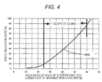
- a horizontal cross-sectional area of an opposing surface, in the stopper part 311, opposed to the lower face 404a of the movable iron core 404 is preferably 25 to 60% of a horizontal cross-sectional area of the lower face 404a of the movable iron core 404.
- a horizontal axis indicates a ratio of an area of the stopper part 311 to the lower face 404a of the movable iron core 404
- a vertical axis indicates a speed reduction rate of the movable iron core 404 as 1400, with respect to a speed at a start of downward displacement after valve closing.
- the stopper part 311 by integrally forming the stopper part 311 with the nozzle body 300b including the movable iron core 404 and the valve element 303 from the outer peripheral direction toward the inner peripheral direction, it is possible to determine the valve-closed-state gap g3 of the movable iron core 404 and the stopper part 311 in the valve closed state by processing of the nozzle body 300b, enabling improvement of performance with a simple method without adding parts or the like.
- the outer diameter 414D of the intermediate member is made smaller than the inner diameter 401D of the fixed iron core. Accordingly, in assembling the fuel injection device, after the gap g1 is determined by the step height 414h of the intermediate member and height h of the plunger rod thick diameter part, the plunger cap 410, the plunger rod 102, the third spring member 406, and the intermediate member 414 can be integrally incorporated into the fuel injection device in advance in a state where the spring force adjusting member 106 and the first spring member 405 are not inserted, enabling stable management of the gap g1 while simplifying the assembly.
- a thick diameter part 414D of the intermediate member 414 is made smaller than the inner diameter 401D of the fixed iron core 401.
- an outermost diameter of a member to be assembled in advance is small, and when an outermost diameter of the plunger cap 410 is larger than an outermost diameter 414D of the intermediate member, the outermost diameter of the plunger cap 410 may be made smaller than the inner diameter 401D of the fixed iron core 401.
- the present invention is not limited to the above embodiments, and various modifications may be included.
- the embodiments described above have been illustrated in detail to facilitate description for easy understanding, and are not necessarily limited to the embodiments that include all the configurations.
- a part of a configuration of an embodiment may be replaced with a configuration of another embodiment, and a configuration of an embodiment may be added with a configuration of another embodiment.
- a part of a configuration of each embodiment may be deleted, replaced, added with another configuration.
- FIG. 5 A second embodiment of the present invention will be described with reference to FIG. 5 .
- explanation of the components having same numerals as those of the first embodiment is omitted since there is no difference in the configuration and effect.
- a difference from the first embodiment is that a stopper member 2400 is joined to a plunger rod 102, and the stopper part 2400 is formed from an inner peripheral side to an outer peripheral side.
- a lower face 404a of a movable iron core 404 collides with an upper face 2311 of the stopper part 2400.
- a second spring member 2407 energizing the movable iron core 404 upward has an indicated position supported by a flat surface portion 2300d provided on the nozzle body 300b, and energizes the movable iron core 404 upward.
- a position of the stopper member 2400 that collides with the movable iron core 404 can be determined in an adjustment process of component assembly, allowing relaxing of requirement of accuracy to an individual component to simplify the component.
Landscapes
- Engineering & Computer Science (AREA)
- General Engineering & Computer Science (AREA)
- Mechanical Engineering (AREA)
- Physics & Mathematics (AREA)
- Chemical & Material Sciences (AREA)
- Combustion & Propulsion (AREA)
- Electromagnetism (AREA)
- Fluid Mechanics (AREA)
- Fuel-Injection Apparatus (AREA)
- Magnetically Actuated Valves (AREA)
Abstract
Description
- The present invention relates to a solenoid valve that is used in an internal combustion engine and mainly injects fuel.
- As a background technology in this technical field, there is
JP 2012-97728A - PTL 1:
JP 2012-97728A - In a fuel injection device, it is required to promote spray atomization and to stabilize an injection amount. A degradation factor of spray atomization is that a fuel flow rate becomes slow in a low lift period at the beginning of opening of a valve element. A degradation factor of injection amount stabilization is that convergence of a valve operation is slow after valve opening. Therefore, it is necessary for the fuel injection device to quickly converge the operation of the valve element after valve opening, while making a start of the opening sharp. In PTL 1, by providing a gap in the displacement direction between the movable iron core and the valve element, only the movable iron core is operated before a start of energization, an impact force at the time of a collision is applied to the valve element upon valve opening, and a low lift engine is shortened. Further, by providing a stopper between the valve elements of the movable iron core, the valve element and the movable iron core can relatively move, enabling stabilization of an injection amount.
- However, a movable element continues to be displaced downward after valve closing, a speed of the movable element is high in returning to a valve-closed standby state, and a member on an upper part of the valve element is lifted. Accordingly, there has been a problem that, when an injection interval is shortened, the gap in the displacement direction becomes small, and a valve opening behavior is not stabilized.
- It is an object of the present invention to make it possible to stably perform a valve opening operation of the valve element even when an injection interval is shortened.
- In order to achieve the above object, the solenoid valve of the present invention includes: a valve element that abuts against and separates from a valve seat to seal fuel; a movable iron core capable of being separated from the valve element; and a fixed iron core arranged opposed to the movable iron core. The solenoid valve also includes: a first spring member that energizes the valve element toward a side of the valve seat; a second spring member that energizes the movable iron core toward the fixed iron core; and a stopper part disposed on the side of the valve seat with respect to the movable iron core, and arranged with the movable iron core via a gap in a displacement direction in a valve closed state. In the solenoid valve, the gap is set such that the movable iron core collides with the stopper part when being displaced in the valve closing direction after the valve element is opened.
- According to a configuration of the present invention, it is possible to stably perform a valve opening operation of the valve element even when an injection interval is shortened.
-
- [
FIG. 1] FIG. 1 is a cross-sectional view showing a structure of a fuel injection device according to a first embodiment of the present invention, and is a longitudinal cross-sectional view showing a cut surface parallel to acenter axis 100a. - [
FIG. 2] FIG. 2 is an enlarged cross-sectional view of an electromagnetic drive part of the fuel injection device shown inFIG. 1 . - [
FIG. 3] FIG. 3 is a graph describing an operation of a movable portion, corresponding to an injection command pulse in an embodiment of the present invention. - [
FIG. 4] FIG. 4 is a graph showing an effect of the invention according to the first embodiment of the present invention. - [
FIG. 5] FIG. 5 is a cross-sectional view showing a structure of a fuel injection device according to a second embodiment of the present invention, and is an enlarged cross-sectional view showing an electromagnetic drive part of the fuel injection device. - Embodiments of the present invention will be described below.
- With reference to
FIGS. 1 and3 , a configuration of a fuel injection device 100 (solenoid valve) as a first embodiment of the present invention will be described. An object of this embodiment is to provide a structure that improves a stability of an operation of a valve element at valve opening and promotes stabilization of an injection amount even when an injection interval is shortened, in a fuel injection device (solenoid valve) in which the valve element receives an impact force from a movable iron core at the valve opening, and the low lift period at the valve opening can be shortened. -
FIG. 1 is a cross-sectional view showing a structure of the fuel injection device according to an embodiment of the present invention, and is a longitudinal cross-sectional view showing a cut surface parallel to acenter axis 100a.FIG. 2 is an enlarged cross-sectional view of anelectromagnetic drive part 400 shown inFIG. 1 .FIG. 3 is a view for describing an operation of a movable portion.FIG. 3 (a) shows an ON/OFF state of an injection command pulse, andFIG. 3 (b) shows displacement of aplunger rod 102 and amovable iron core 404 with a valve closed state of theplunger rod 102 asdisplacement 0. - The
fuel injection device 100 is configured by afuel supply part 200 that supplies fuel, anozzle part 300 provided with avalve part 300a at a tip portion to permit or interrupt a flow of the fuel, and theelectromagnetic drive part 400 that drives thevalve part 300a. In this embodiment, an electromagnetic fuel injection device for an internal combustion engine that uses gasoline as fuel will be described as an example. Note that thefuel supply part 200, thevalve part 300a, thenozzle part 300, and theelectromagnetic drive part 400 indicate corresponding portions with respect to the cross section shown inFIG. 1 , and do not indicate a single component. - In the
fuel injection device 100 of this embodiment, thefuel supply part 200 is formed at an upper end side of the figure, thenozzle part 300 is formed at a lower end side, and theelectromagnetic drive part 400 is formed between thefuel supply part 200 and thenozzle part 300. That is, thefuel supply part 200, theelectromagnetic drive part 400, and thenozzle part 300 are arranged in this order along a direction of thecenter axis 100a. - An end portion of the
fuel supply part 200 on an opposite side to thenozzle part 300 is connected to a fuel pipe (not shown). An end portion of thenozzle part 300 on an opposite side to thefuel supply part 200 is inserted into a mounting hole (insertion hole) formed in an intake pipe (not shown) or a combustion-chamber forming member (cylinder block, cylinder head, or the like) of the internal combustion engine. The electromagneticfuel injection device 100 receives fuel supply from the fuel pipe through thefuel supply part 200, and injects fuel from the tip portion of thenozzle part 300 into the intake pipe or the combustion chamber. Inside thefuel injection device 100, from the end portion of thefuel supply part 200 to the tip portion of thenozzle part 300, a fuel passage 101 (101a to 101f) is formed such that the fuel flows substantially along thecenter axis 100a direction of the electromagneticfuel injection device 100. - In the following description, for both end portions of the
fuel injection device 100 in the direction along thecenter axis 100a, the end portion or the end portion side positioned on the opposite side to thenozzle part 300, of thefuel supply part 200, is referred to as a base end portion or a base end side, and the end portion or the end portion side positioned on the opposite side to thefuel supply part 200, of thenozzle part 300, is referred to as a tip portion or a tip side. Further, with reference to a vertical direction inFIG. 1 , description is given with "upper" or "lower" added to each part forming the electromagnetic fuel injection device. This is done to make the description easy to understand, and a mounting configuration of the electromagnetic fuel injection device for the internal combustion engine is not limited to this vertical direction. - Hereinafter, configurations of the
fuel supply part 200, theelectromagnetic drive part 400, and thenozzle part 300 will be described in detail. - The
fuel supply part 200 is configured by afuel pipe 201. One end portion (upper end portion) of thefuel pipe 201 is provided with afuel supply port 201a, and thefuel passage 101a is formed inside thefuel pipe 201 to penetrate in the direction along thecenter axis 100a. Another end potion (lower end portion) of thefuel pipe 201 is joined to one end portion (upper end portion) of a fixediron core 401. - On an outer peripheral side of the upper end portion of the
fuel pipe 201, an O-ring 202 and abackup ring 203 are provided. The O-ring 202 functions as a seal to prevent fuel leakage when thefuel supply port 201a is mounted to the fuel pipe. In addition, thebackup ring 203 is for backing up the O-ring 202. Thebackup ring 203 may be formed by laminating a plurality of ring-shaped members. Inside thefuel supply port 201a, there is disposed afilter 204 that filters foreign matter mixed in the fuel. - The
nozzle part 300 includes anozzle body 300b, and thevalve part 300a is formed at a tip portion (lower end portion) of thenozzle body 300b. Thenozzle body 300b is a hollow cylindrical body, and forms afuel passage 101f on an upstream side of thevalve part 300a. Astopper part 311 is formed in the lowerfuel passage portion 101e portion of theelectromagnetic drive part 400. On an outer peripheral surface of the tip portion of thenozzle body 300b, there is provided atip seal 103 that maintains airtightness in mounting to the internal combustion engine. - The
valve part 300a includes an injection-hole forming member 301, aguide member 302, and avalve element 303 provided at one end portion (lower end side tip portion) of theplunger rod 102. The injection-hole forming member 301 is configured by avalve seat 301a that is in contact with the valve element to seal the fuel, and afuel injection hole 301b that injects the fuel. The injection-hole forming member 301 is inserted and fixed into a recess inner peripheral surface 300ba formed at the tip portion of thenozzle body 300b. Here, an outer periphery of a tip end face of the injection-hole forming member 301 and an inner periphery of a tip end face of thenozzle body 300b are welded to seal the fuel. - The
guide part 302 is on an inner peripheral side of the injection-hole forming member 301, and forms a guide surface on the tip end side (lower end side) of theplunger rod 102 to guide a movement of theplunger rod 102 in the direction along the center axis 100a (valve opening/closing direction). - The
electromagnetic drive part 400 is configured by the fixediron core 401, acoil 402, ahousing 403, themovable iron core 404, anintermediate member 414, aplunger cap 410, afirst spring member 405, athird spring member 406, and asecond spring member 407. The fixediron core 401 is also referred to as a fixed core. Themovable iron core 404 is also referred to as a movable core, a movable element, or an armature. - The fixed
iron core 401 has thefuel passage 101c in a center portion, and ajoint part 401a with thefuel pipe 201. An outerperipheral surface 401b of the fixediron core 401 is fitted and joined to a large diameter innerperipheral portion 300c of thenozzle body 300b, and an outerperipheral surface 401e having a larger diameter than the outerperipheral surface 401b is fitted and joined to an outer-peripheral-side fixediron core 401d. Thecoil 402 is wound around an outer peripheral side of the fixediron core 401 and alarge diameter portion 300c of the cylindrical member. - The
housing 403 is provided to surround an outer peripheral side of thecoil 402, and forms an outer periphery of the electromagneticfuel injection device 100. An upper-end-side innerperipheral surface 403a of thehousing 403 is connected to an outerperipheral surface 401f of the outer-peripheral-side fixediron core 401d joined to the outerperipheral surface 401e of the fixediron core 401. - The
movable iron core 404 is disposed on alower end face 401g side of the fixediron core 401. Anupper end face 404c of themovable iron core 404 is opposed to alower end face 401g of the fixediron core 401 with a gap g2 in a valve closed state. The outer peripheral surface of themovable iron core 404 is opposed to the inner peripheral surface of thelarge diameter portion 300c of thenozzle body 300b via a slight gap, and themovable iron core 404 is provided inside thelarge diameter portion 300c of the cylindrical member to be movable in the direction along thecenter axis 100a. - A magnetic path is formed such that a magnetic flux circulates in the fixed
iron core 401, themovable iron core 404, thehousing 403, and thelarge diameter portion 300c of the cylindrical member. Themovable iron core 404 is attracted in a direction of the fixediron core 401 by a magnetic attraction force generated by the magnetic flux flowing between thelower end face 401g of the fixediron core 401 and theupper end face 404c of themovable iron core 404. - In a center portion of the
movable iron core 404, there is formed a recessedpart 404b recessed from the upper end face 404c side to alower end face 404a side. On theupper end face 404c and a bottom face of the recessedpart 404b, afuel passage hole 404d is formed as thefuel passage 101d penetrating to thelower end face 404a side in the direction along thecenter axis 100a. On the bottom face of the recessedpart 404b, a throughhole 404e penetrating to thelower end face 404a side is formed in the direction along thecenter axis 100a. Theplunger rod 102 is provided to pass through the throughhole 404e. - The
plunger rod 102 is fixed with theplunger cap 410 by fitting, and has athick diameter part 102a. Theintermediate member 414 is a cylindrical member having a recessed part serving as a step on inner and outer peripheries, in which an innerperipheral surface 414a abuts against anupper face 102b of the plunger rodthick diameter part 102a, and an outerperipheral surface 414b abuts against thebottom face 404b' of the recess part of the movable iron core. Between alower face 102c of the thick diameter part and thebottom face 404b' of the movable iron core recessedpart 404b, a gap g1 (pre-stroke gap) is provided. A length obtained by subtracting height h between theupper face 102b and thelower face 102c of the plunger rod thick diameter part fromheight 414h of the recessed part step of theintermediate member 414 is the gap g1 described above. Below themovable iron core 404, there is formed thestopper part 311 that is a part of thenozzle body 300b and extends from the outer peripheral side of thenozzle body 300b to the inner peripheral side to an inner peripheral side cavity, to adiameter portion 311a. In the valve closed state, there is a gap g3 between alower face 404a of themovable iron core 404 and thestopper part 311. - An upper end portion of the
first spring member 405 abuts against a lower end face of a springforce adjusting member 106, and a lower end portion of thefirst spring member 405 abuts against an upper spring bearing 410a of theplunger cap 410, to energize theplunger rod 102 downward via theplunger cap 410. An upper end portion of thethird spring member 406 abuts against a lowerspring bearing part 410b of theplunger cap 410, and a lower end portion of thethird spring member 406 abuts against anupper face 414c of theintermediate member 414, to energize theintermediate member 414 downward. An upper end portion of thesecond spring 407 abuts against thelower face 404a of themovable iron core 404, and a lower end portion of thesecond spring 407 abuts against a steppedportion 300d of thenozzle body 300b, to energize themovable iron core 404 upward. - The
coil 402 is wound on a bobbin and assembled to the outer peripheral side of the fixediron core 401 and thelarge diameter portion 300b of the cylindrical member, and a resin material is molded around thecoil 402. By a resin material used for this molding, aconnector 105 having a terminal 104 drawn out from thecoil 402 is integrally molded. - Next, an operation of the
fuel injection device 100 in this embodiment and features of this embodiment will be described. Description is given mainly with reference toFIG. 2 , which is an enlarged view of theelectromagnetic drive part 400, andFIG. 3 , which describes an operation of the movable portion. - In a valve closed state where the
coil 402 is not energized, theplunger rod 102 abuts against thevalve seat 301a to close the valve, by a force obtained by subtracting an energizing force of thethird spring member 406, from an energizing force of thefirst spring member 405 energizing theplunger rod 102 in the valve closing direction and thesecond spring member 407. This state is called a valve-closed stationary state. Here, themovable iron core 404 abuts against an outer peripheral steppedportion 414b of theintermediate member 414, and is disposed in a valve closing position. In the valve closed state of the fuel injection device of this embodiment, gaps associated with a movable part relating to a valve opening operation are configured as follows. - Between the
upper end face 404c of themovable iron core 404 and thelower end face 401g of the fixediron core 401, a gap g2 is provided. Between aflat surface 404b' of the recessedpart 404b of themovable iron core 404 and thelower face 102c of the plunger rod thick diameter part, the gap g1 is provided. A relationship between g1 and g2 is g2 > g1. - In the valve closed state, there is the gap g3 between the
lower face 404a of themovable iron core 404 and thestopper part 311. The gap g3 is set such that only themovable iron core 404 collide with thestopper part 311 when being displaced downward after the opening and closing valve operation of theplunger rod 102. - Namely, the solenoid valve (fuel injection device) of this embodiment includes the
valve element 303 that abuts against and separates from thevalve seat 301a to seal the fuel, themovable iron core 404 capable of being separated from thevalve element 303, and the fixediron core 401 arranged opposed to themovable iron core 404. There are also provided thefirst spring member 405 that energizes thevalve element 303 toward a side of thevalve seat 301a, thesecond spring member 407 that energizes themovable iron core 404 toward the fixediron core 401, and thestopper part 311 disposed on the side of thevalve seat 301a with respect to themovable iron core 404, and disposed with themovable iron core 404 via the valve-closed-state gap g3 in a displacement direction in the valve closed state. Additionally, the valve-closed-state gap g3 is set such that themovable iron core 404 collides with thestopper part 311 when being displaced in the valve closing direction after opening of thevalve element 303. - Namely, the solenoid valve of this embodiment is arranged with the
valve element 303 via the pre-stroke gap g1 in an axial direction in the valve closed state, and provided with themovable iron core 404 that moves in the valve opening direction to axially contact with thevalve element 303, and thestopper part 311 disposed on a side of a valve seat part (valve seat 301a) with respect to themovable iron core 404, and arranged in an axial direction with themovable iron core 404 via the valve-closed-state gap g3 in the valve closed state. This valve-closed-state gap g3 is set such that themovable iron core 404 collides with thestopper part 311 when returning to the valve closing direction after valve opening, in the solenoid valve. - After energization to the coil 402 (P1), a magnetomotive force is generated by the electromagnet formed by the fixed
iron core 401, thecoil 402, and thehousing 403. This magnetomotive force causes a flow of a magnetic flux that is formed to surround thecoil 402, and circulates the magnetic path formed by the fixediron core 401, thehousing 403, thethick diameter part 300d of the nozzle body, and themovable iron core 404. Here, a magnetic attractive force acts between theupper end face 404c of themovable iron core 404 and thelower end face 401g of the fixediron core 401, and themovable iron core 404 and theintermediate member 414 are displaced toward the fixediron core 401. Then, themovable iron core 404 is displaced by g1 (404D1) until abutting against thelower face 102c of the thick diameter part of the plunger rod. Here, theplunger rod 102 does not move (102D1). - Then, when the
movable iron core 404 abuts against thelower face 102c of the thick diameter part of the plunger rod at timing t1, theplunger rod 102 receives an impact force from themovable iron core 404 and is lifted, and theplunger rod 102 is separated from thevalve seat 301a. This causes a gap to be formed in the valve seat part, to open the fuel passage. Since the valve is opened by receiving the impact force, theplunger rod 102 rises sharply (3A). - After that, when the
plunger rod 102 is displaced by g2 - g1, and anupper face 404c of themovable iron core 404 abuts against alower face 401g of the fixediron core 401 at timing t2, theplunger rod 102 is displaced upward (3B), themovable iron core 404 is displaced downward (3B'). Then, theplunger rod 102 and themovable iron core 404 come into contact with each other again (3C) and then separate from each other again, the plunger rod is displaced upward (3D), themovable iron core 404 is displaced downward (3D'), and then the displacement is stabilized at g2 - g1 (3E). - In this embodiment, the
intermediate member 414 is provided below thethird spring 406 that applies a spring force to themovable iron core 404 and theplunger rod 102, and disposed to abut against thesurface 404b' of the recessed part of themovable iron core 404, and theupper face 102b of the thick diameter part of theplunger rod 102. Accordingly, themovable iron core 404, theplunger rod 102, and theintermediate member 414 perform the valve opening operation, and when themovable iron core 404 and the fixediron core 401 collide with each other at timing t2, themovable iron core 404 moves downward, but theintermediate member 414 and theplunger rod 102 continue to move upward. - In this state, no spring force acting between the
movable iron core 404 and theplunger rod 102 is generated, and the spring force is separated. Therefore, the spring force that changes according to the movement of themovable iron core 404 is not transmitted to theplunger rod 102, on the contrary, there is no possibility of transmitting a spring force that changes with the movement of theplunger rod 102 to themovable iron core 404, causing each other's independent oscillation along with the collision (3B, 3B'). Further, in an additional collision (3C), while themovable iron core 404 bounds downward (3D') and theplunger rod 102 bounds upward (3D) again, themovable iron core 404 and theplunger rod 102 do not transmit or receive the force, but move without applying a spring force that changes along with the each other's movement, and the force of theplunger rod 102 and themovable iron core 404 is small. Therefore, the convergence of the bounding of the movable part becomes faster (3E) than that in a case where a spring force that changes along with the each other's movement is applied. This effect enables stabilization of the fuel injection amount. - Further, in the valve closed state, the gap g1 in which the
movable element 404 is displaced is defined by a difference betweenheight 414h of the recessed part of theintermediate member 414 and height h of the plunger rod thick diameter part (height h between theupper face 102b and thelower face 102c of 102a), which is determined by dimensions of parts, eliminating necessity of adjustment in assembling process, and enabling simple assembly process. - When the energization to the
coil 402 is interrupted (P2) at timing t3, the magnetic force starts to disappear, and the valve closing operation is performed by an energizing force of the spring in a downward direction. After the displacement of theplunger rod 102 becomes zero at timing t4, the plunger rod abuts against thevalve seat 301a to complete the valve closing (102D2). - After moving to the initial position g1 (404D2) after the valve closing, the
movable iron core 404 is further displaced downward and collides with thestopper part 311 at a position of g3 + g1. This collision reduces kinetic energy possessed during the downward movement after the valve closing to decrease the speed, and themovable iron core 404 bounds and stops at the position g1 (404D3). Since this action prevents a state where the gap g1 is shortened, improving the stability of the valve opening operation. Namely, using a valve-opened-state gap g3 enables energy dissipation by the collision or a squeeze effect when themovable iron core 404 approaches thestopper part 311. This allows the pre-stroke gap g1 to be secured, enabling injection even at short pulse intervals. - In the valve closed state, there is the gap g3 between the
lower face 404a of themovable iron core 404 and thestopper part 311. Therefore, when themovable iron core 404 collides with thestopper part 311 during the downward movement after the opening/closing valve operation, the gap of theflat surface 404b' of the recessedpart 404b of themovable iron core 404 and thelower face 102c of the plunger rod thick diameter part is larger than the gap g1 in the valve closed state. Consequently, it is possible to dissipate the kinetic energy that has been possessed during the downward displacement before returning to the position of g1, and to stop at the position of g1. This prevents the gap g1 from being shortened, improving the stability of the valve opening operation. - In the absence of the
stopper part 311, as indicated by 404D4, themovable iron core 404 continues the downward displacement and returns to the g1 with speed, and is displaced upward without stopping at g1, causing a state where the gap, of themovable iron core 404 and theplunger rod 102, is small in the displacement direction in the valve closed state. - The inventors of the present invention have found that the gap g3 between the
lower face 404a of themovable iron core 404 and thestopper part 311 needs to be equal to or smaller than expression 1 in the valve closed state. Symbols in the formula are the following physical quantities. In the valve closed state, the downward energizing force of thefirst spring member 405 is Fssp, the downward energizing force of thethird spring member 406 is Fmsp, the upward energizing force of thesecond spring member 407 is Fzsp, sum of the spring forces acting on themovable iron core 404, theplunger rod 102, and theintermediate member 414 in the valve closed state is F with the downward direction defined as positive, mass of theplunger rod 102 is mp, mass of theintermediate member 414 is ms, mass of themovable iron core 404 is ma, and total mass of the movable part is M. Note that g1 and g2 have the following relationship as described above. The gap g1 is between theflat surface 404b' of the recessedpart 404b of themovable iron core 404 and thelower face 102c of the plunger rod thick diameter part, and the gap g2 is between theupper end face 404c of themovable iron core 404 and thelower end face 401g of the fixediron core 401.
- Namely, setting g3 to be shorter than a downward displacement length of the
movable iron core 404 after the valve closing causes themovable iron core 404 to collide with thestopper part 311, and reduces the kinetic energy possessed during the downward displacement after valve closing to decrease the speed, enabling themovable iron core 404 to bound at thestopper part 311 and stop at the position g1. Since this action prevents a state where the gap g1 is shortened, improving the stability of the valve opening operation. - The present inventors have further found that, in the configuration of this embodiment, a horizontal cross-sectional area of an opposing surface, in the
stopper part 311, opposed to thelower face 404a of themovable iron core 404 is preferably 25 to 60% of a horizontal cross-sectional area of thelower face 404a of themovable iron core 404. - In
FIG. 5 , a horizontal axis indicates a ratio of an area of thestopper part 311 to thelower face 404a of themovable iron core 404, and a vertical axis indicates a speed reduction rate of themovable iron core 404 as 1400, with respect to a speed at a start of downward displacement after valve closing. As the cross-sectional area of thestopper part 311 becomes larger than the cross-sectional area of thelower face 404a of themovable iron core 404, an effect of the fluid damper acts in the collision to decrease the speed. In a state where the speed is decreased, themovable iron core 404 collides with thestopper part 311, and returns to g1, which is the valve-closed standby state. This prevents the pre-stroke gap g1 from being shortened in the valve closed state of themovable iron core 404 and thevalve element 102, improving the stability of the valve opening operation. - Additionally, in the configuration of this embodiment, by integrally forming the
stopper part 311 with thenozzle body 300b including themovable iron core 404 and thevalve element 303 from the outer peripheral direction toward the inner peripheral direction, it is possible to determine the valve-closed-state gap g3 of themovable iron core 404 and thestopper part 311 in the valve closed state by processing of thenozzle body 300b, enabling improvement of performance with a simple method without adding parts or the like. - Moreover, in the configuration of this embodiment, the
outer diameter 414D of the intermediate member is made smaller than theinner diameter 401D of the fixed iron core. Accordingly, in assembling the fuel injection device, after the gap g1 is determined by thestep height 414h of the intermediate member and height h of the plunger rod thick diameter part, theplunger cap 410, theplunger rod 102, thethird spring member 406, and theintermediate member 414 can be integrally incorporated into the fuel injection device in advance in a state where the springforce adjusting member 106 and thefirst spring member 405 are not inserted, enabling stable management of the gap g1 while simplifying the assembly. In this embodiment, athick diameter part 414D of theintermediate member 414 is made smaller than theinner diameter 401D of the fixediron core 401. However, it is only necessary that an outermost diameter of a member to be assembled in advance is small, and when an outermost diameter of theplunger cap 410 is larger than anoutermost diameter 414D of the intermediate member, the outermost diameter of theplunger cap 410 may be made smaller than theinner diameter 401D of the fixediron core 401. - In this embodiment, even if the recessed
part 404b of the movable iron core does not exist but is the same surface as 404c, it is possible to obtain the same operation effect as this embodiment. This is because providing the recessedpart 404b of the movable iron core allows theintermediate member 414 to be arranged further downward, a vertical length of theplunger rod 102 to be shortened, and theplunger rod 102 to be configured with high accuracy. - Note that the present invention is not limited to the above embodiments, and various modifications may be included. For example, the embodiments described above have been illustrated in detail to facilitate description for easy understanding, and are not necessarily limited to the embodiments that include all the configurations. Additionally, a part of a configuration of an embodiment may be replaced with a configuration of another embodiment, and a configuration of an embodiment may be added with a configuration of another embodiment. Moreover, a part of a configuration of each embodiment may be deleted, replaced, added with another configuration.
- A second embodiment of the present invention will be described with reference to
FIG. 5 . In the figure, explanation of the components having same numerals as those of the first embodiment is omitted since there is no difference in the configuration and effect. - A difference from the first embodiment is that a
stopper member 2400 is joined to aplunger rod 102, and thestopper part 2400 is formed from an inner peripheral side to an outer peripheral side. In addition, alower face 404a of amovable iron core 404 collides with anupper face 2311 of thestopper part 2400. Further, asecond spring member 2407 energizing themovable iron core 404 upward has an indicated position supported by aflat surface portion 2300d provided on thenozzle body 300b, and energizes themovable iron core 404 upward. - Due to the configuration of this embodiment, a position of the
stopper member 2400 that collides with themovable iron core 404 can be determined in an adjustment process of component assembly, allowing relaxing of requirement of accuracy to an individual component to simplify the component. - According to the present invention as well, after the opening/closing valve operation, only the
movable iron core 404 collides with thestopper part 2400 during downward displacement. This collision reduces the kinetic energy possessed during the downward movement after the valve closing to decrease the speed, and themovable iron core 404 stops at the position g1, which prevents the pre-stroke gap g1 from being shortened in valve closing, enabling improvement of stability of an injection amount. -
- 100
- fuel injection device
- 101
- fuel passage
- 102
- plunger rod
- 200
- fuel supply part
- 300
- nozzle part
- 301a
- valve seat
- 301b
- fuel injection hole
- 311
- stopper part
- 400
- electromagnetic drive part
- 401
- fixed iron core
- 402
- coil
- 403
- housing
- 404
- movable iron core
- 405
- first spring member
- 406
- third spring member
- 407
- second spring member
- 414
- intermediate member
Claims (8)
- A solenoid valve provided with a valve element that abuts against and separates from a valve seat to seal fuel, a movable iron core capable of being separated from the valve element, and a fixed iron core arranged opposed to the movable iron core, the solenoid valve comprising:a first spring member that energizes the valve element toward a side of the valve seat;a second spring member that energizes the movable iron core toward the fixed iron core; anda stopper part disposed on the side of the valve seat with respect to the movable iron core, and arranged with the movable iron core via a gap in a displacement direction in a valve closed state, whereinthe gap is set such that the movable iron core collides with the stopper part when being displaced in the valve closing direction after the valve element is opened.
- A solenoid valve comprising:a movable iron core that is arranged with a valve element via a pre-stroke gap in an axial direction in a valve closed state, and moves in a valve opening direction to axially contact with the valve element; anda stopper part arranged on a side of a valve seat with respect to the movable iron core, and arranged with the movable iron core via a gap in an axial direction in a valve closed state.
- The solenoid valve according to claim 2, wherein
the gap is set such that the movable iron core collides with the stopper part when returning to the valve closing direction after valve opening. - The solenoid valve according to claim 1, wherein
a pre-stroke gap is formed between the valve element and the movable iron core in a displacement direction in the valve closed state. - The solenoid valve according to claim 1 or 2, wherein
an area of an opposing surface, in the stopper part, opposed to the movable iron core is 25 to 60% of an area of the movable iron core in a horizontal direction. - The solenoid valve according to claim 1, wherein
when the gap is defined as g3, a direction toward the side of the valve seat is defined as positive, a total of an energizing force acting on a movable member is F, an upward energizing force of the second spring member is Fzsp, total mass of the movable member is M, mass of the movable iron core is ma, a gap of the movable iron core and the fixed iron core in a valve closed state in a displacement direction is g2, and a gap of the valve element and the movable iron core in a valve closed state in a displacement direction is g1, g3 < F/M * ma/Fzsp * (g2 - g1) - g1 ··· (1). - The solenoid valve according to claim 1, wherein
the stopper part is joined to the fixed iron core, and is integrally formed with a nozzle holder containing the movable iron core and the valve element, from an outer peripheral direction to an inner peripheral direction. - The solenoid valve according to claim 1, wherein
the stopper part is integrally formed with the valve element, from an inner peripheral direction to an outer peripheral direction.
Applications Claiming Priority (2)
| Application Number | Priority Date | Filing Date | Title |
|---|---|---|---|
| JP2015129463A JP6571410B2 (en) | 2015-06-29 | 2015-06-29 | solenoid valve |
| PCT/JP2016/068026 WO2017002638A1 (en) | 2015-06-29 | 2016-06-17 | Electromagnetic valve |
Publications (3)
| Publication Number | Publication Date |
|---|---|
| EP3315761A1 true EP3315761A1 (en) | 2018-05-02 |
| EP3315761A4 EP3315761A4 (en) | 2019-02-20 |
| EP3315761B1 EP3315761B1 (en) | 2021-04-07 |
Family
ID=57608772
Family Applications (1)
| Application Number | Title | Priority Date | Filing Date |
|---|---|---|---|
| EP16817746.7A Active EP3315761B1 (en) | 2015-06-29 | 2016-06-17 | Electromagnetic valve |
Country Status (5)
| Country | Link |
|---|---|
| US (1) | US10267283B2 (en) |
| EP (1) | EP3315761B1 (en) |
| JP (1) | JP6571410B2 (en) |
| CN (1) | CN107709751B (en) |
| WO (1) | WO2017002638A1 (en) |
Families Citing this family (10)
| Publication number | Priority date | Publication date | Assignee | Title |
|---|---|---|---|---|
| SE540880C2 (en) * | 2016-09-28 | 2018-12-11 | Freevalve Ab | Multi-way valve as well as actuator comprising such a multi-way valve |
| US10641410B2 (en) * | 2017-02-09 | 2020-05-05 | Beijingwest Industries Co., Ltd. | Pneumatic valve for air suspension systems |
| CN111344483B (en) | 2017-11-22 | 2022-03-08 | 日立安斯泰莫株式会社 | fuel injection device |
| WO2019163383A1 (en) * | 2018-02-23 | 2019-08-29 | 日立オートモティブシステムズ株式会社 | Fuel injection valve and method for assembling same |
| DE102019103207A1 (en) * | 2018-02-27 | 2019-08-29 | Borgwarner Inc. | ELECTROMAGNETIC VALVE AND HYDRAULIC CONTROL MODULE THAT INCLUDES THIS |
| JP7377035B2 (en) * | 2019-09-09 | 2023-11-09 | カヤバ株式会社 | Solenoids, solenoid valves, and shock absorbers |
| CN112696522B (en) | 2019-10-22 | 2022-05-03 | 浙江三花制冷集团有限公司 | Electromagnetic valve |
| US11721465B2 (en) | 2020-04-24 | 2023-08-08 | Rain Bird Corporation | Solenoid apparatus and methods of assembly |
| JP7724495B2 (en) * | 2021-07-27 | 2025-08-18 | 三菱重工エンジン&ターボチャージャ株式会社 | Solenoid device and solenoid valve of fuel injection device |
| DE102022202027A1 (en) * | 2022-02-28 | 2023-08-31 | Robert Bosch Gesellschaft mit beschränkter Haftung | Method for controlling an electromagnetically controllable gas valve, control unit |
Family Cites Families (11)
| Publication number | Priority date | Publication date | Assignee | Title |
|---|---|---|---|---|
| JP2568514Y2 (en) * | 1992-06-19 | 1998-04-15 | 本田技研工業株式会社 | Electromagnetic fuel injection valve |
| DE19650865A1 (en) * | 1996-12-07 | 1998-06-10 | Bosch Gmbh Robert | magnetic valve |
| DE19708104A1 (en) * | 1997-02-28 | 1998-09-03 | Bosch Gmbh Robert | magnetic valve |
| EP2077389B1 (en) * | 2006-09-25 | 2013-01-30 | Hitachi Ltd. | Fuel injection valve |
| JP4483940B2 (en) * | 2007-12-21 | 2010-06-16 | 株式会社デンソー | Fuel injection valve |
| JP5218487B2 (en) * | 2009-12-04 | 2013-06-26 | 株式会社デンソー | Fuel injection valve |
| US8453951B2 (en) * | 2010-09-22 | 2013-06-04 | Delphi Technologies, Inc. | Fuel injector |
| JP5768536B2 (en) * | 2010-10-05 | 2015-08-26 | 株式会社デンソー | Fuel injection valve |
| JP5822269B2 (en) * | 2011-11-11 | 2015-11-24 | 株式会社ケーヒン | Electromagnetic fuel injection valve |
| JP5982210B2 (en) * | 2012-07-27 | 2016-08-31 | 日立オートモティブシステムズ株式会社 | Electromagnetic fuel injection valve |
| JP2013064414A (en) * | 2013-01-18 | 2013-04-11 | Denso Corp | Fuel injection valve |
-
2015
- 2015-06-29 JP JP2015129463A patent/JP6571410B2/en active Active
-
2016
- 2016-06-17 US US15/579,682 patent/US10267283B2/en active Active
- 2016-06-17 EP EP16817746.7A patent/EP3315761B1/en active Active
- 2016-06-17 CN CN201680035881.8A patent/CN107709751B/en active Active
- 2016-06-17 WO PCT/JP2016/068026 patent/WO2017002638A1/en not_active Ceased
Also Published As
| Publication number | Publication date |
|---|---|
| EP3315761B1 (en) | 2021-04-07 |
| JP2017014921A (en) | 2017-01-19 |
| US10267283B2 (en) | 2019-04-23 |
| US20180163685A1 (en) | 2018-06-14 |
| CN107709751B (en) | 2020-04-24 |
| WO2017002638A1 (en) | 2017-01-05 |
| CN107709751A (en) | 2018-02-16 |
| JP6571410B2 (en) | 2019-09-04 |
| EP3315761A4 (en) | 2019-02-20 |
Similar Documents
| Publication | Publication Date | Title |
|---|---|---|
| EP3315761B1 (en) | Electromagnetic valve | |
| JP6345557B2 (en) | Fuel injection device | |
| US10030621B2 (en) | Fuel injection valve | |
| US10280886B2 (en) | Fuel injection valve | |
| EP3343079B1 (en) | Solenoid valve | |
| EP2851551B1 (en) | Fluid injection valve | |
| US11629678B2 (en) | Fuel injection valve and method for assembling same | |
| JP6861297B2 (en) | Fuel injection device | |
| JP6101610B2 (en) | Electromagnetic fuel injection valve | |
| US10815949B2 (en) | Fuel injection device | |
| JP6282175B2 (en) | Switchgear | |
| JP6800238B2 (en) | Fuel injection device | |
| US11242830B2 (en) | Fuel injection valve | |
| JP7171448B2 (en) | fuel injector |
Legal Events
| Date | Code | Title | Description |
|---|---|---|---|
| STAA | Information on the status of an ep patent application or granted ep patent |
Free format text: STATUS: THE INTERNATIONAL PUBLICATION HAS BEEN MADE |
|
| PUAI | Public reference made under article 153(3) epc to a published international application that has entered the european phase |
Free format text: ORIGINAL CODE: 0009012 |
|
| STAA | Information on the status of an ep patent application or granted ep patent |
Free format text: STATUS: REQUEST FOR EXAMINATION WAS MADE |
|
| 17P | Request for examination filed |
Effective date: 20180129 |
|
| AK | Designated contracting states |
Kind code of ref document: A1 Designated state(s): AL AT BE BG CH CY CZ DE DK EE ES FI FR GB GR HR HU IE IS IT LI LT LU LV MC MK MT NL NO PL PT RO RS SE SI SK SM TR |
|
| AX | Request for extension of the european patent |
Extension state: BA ME |
|
| DAV | Request for validation of the european patent (deleted) | ||
| DAX | Request for extension of the european patent (deleted) | ||
| A4 | Supplementary search report drawn up and despatched |
Effective date: 20190118 |
|
| RIC1 | Information provided on ipc code assigned before grant |
Ipc: F02M 51/06 20060101AFI20190114BHEP |
|
| GRAP | Despatch of communication of intention to grant a patent |
Free format text: ORIGINAL CODE: EPIDOSNIGR1 |
|
| STAA | Information on the status of an ep patent application or granted ep patent |
Free format text: STATUS: GRANT OF PATENT IS INTENDED |
|
| INTG | Intention to grant announced |
Effective date: 20201214 |
|
| GRAS | Grant fee paid |
Free format text: ORIGINAL CODE: EPIDOSNIGR3 |
|
| GRAA | (expected) grant |
Free format text: ORIGINAL CODE: 0009210 |
|
| STAA | Information on the status of an ep patent application or granted ep patent |
Free format text: STATUS: THE PATENT HAS BEEN GRANTED |
|
| AK | Designated contracting states |
Kind code of ref document: B1 Designated state(s): AL AT BE BG CH CY CZ DE DK EE ES FI FR GB GR HR HU IE IS IT LI LT LU LV MC MK MT NL NO PL PT RO RS SE SI SK SM TR |
|
| REG | Reference to a national code |
Ref country code: GB Ref legal event code: FG4D |
|
| REG | Reference to a national code |
Ref country code: AT Ref legal event code: REF Ref document number: 1379995 Country of ref document: AT Kind code of ref document: T Effective date: 20210415 Ref country code: CH Ref legal event code: EP |
|
| REG | Reference to a national code |
Ref country code: DE Ref legal event code: R096 Ref document number: 602016055765 Country of ref document: DE |
|
| REG | Reference to a national code |
Ref country code: IE Ref legal event code: FG4D |
|
| REG | Reference to a national code |
Ref country code: LT Ref legal event code: MG9D |
|
| REG | Reference to a national code |
Ref country code: NL Ref legal event code: MP Effective date: 20210407 Ref country code: AT Ref legal event code: MK05 Ref document number: 1379995 Country of ref document: AT Kind code of ref document: T Effective date: 20210407 |
|
| REG | Reference to a national code |
Ref country code: DE Ref legal event code: R081 Ref document number: 602016055765 Country of ref document: DE Owner name: HITACHI ASTEMO, LTD., HITACHINAKA-SHI, JP Free format text: FORMER OWNER: HITACHI AUTOMOTIVE SYSTEMS, LTD., HITACHINAKA-SHI, LBARAKI, JP |
|
| RAP4 | Party data changed (patent owner data changed or rights of a patent transferred) |
Owner name: HITACHI ASTEMO, LTD. |
|
| PG25 | Lapsed in a contracting state [announced via postgrant information from national office to epo] |
Ref country code: FI Free format text: LAPSE BECAUSE OF FAILURE TO SUBMIT A TRANSLATION OF THE DESCRIPTION OR TO PAY THE FEE WITHIN THE PRESCRIBED TIME-LIMIT Effective date: 20210407 Ref country code: LT Free format text: LAPSE BECAUSE OF FAILURE TO SUBMIT A TRANSLATION OF THE DESCRIPTION OR TO PAY THE FEE WITHIN THE PRESCRIBED TIME-LIMIT Effective date: 20210407 Ref country code: NL Free format text: LAPSE BECAUSE OF FAILURE TO SUBMIT A TRANSLATION OF THE DESCRIPTION OR TO PAY THE FEE WITHIN THE PRESCRIBED TIME-LIMIT Effective date: 20210407 Ref country code: HR Free format text: LAPSE BECAUSE OF FAILURE TO SUBMIT A TRANSLATION OF THE DESCRIPTION OR TO PAY THE FEE WITHIN THE PRESCRIBED TIME-LIMIT Effective date: 20210407 Ref country code: BG Free format text: LAPSE BECAUSE OF FAILURE TO SUBMIT A TRANSLATION OF THE DESCRIPTION OR TO PAY THE FEE WITHIN THE PRESCRIBED TIME-LIMIT Effective date: 20210707 Ref country code: AT Free format text: LAPSE BECAUSE OF FAILURE TO SUBMIT A TRANSLATION OF THE DESCRIPTION OR TO PAY THE FEE WITHIN THE PRESCRIBED TIME-LIMIT Effective date: 20210407 |
|
| PG25 | Lapsed in a contracting state [announced via postgrant information from national office to epo] |
Ref country code: IS Free format text: LAPSE BECAUSE OF FAILURE TO SUBMIT A TRANSLATION OF THE DESCRIPTION OR TO PAY THE FEE WITHIN THE PRESCRIBED TIME-LIMIT Effective date: 20210807 Ref country code: GR Free format text: LAPSE BECAUSE OF FAILURE TO SUBMIT A TRANSLATION OF THE DESCRIPTION OR TO PAY THE FEE WITHIN THE PRESCRIBED TIME-LIMIT Effective date: 20210708 Ref country code: LV Free format text: LAPSE BECAUSE OF FAILURE TO SUBMIT A TRANSLATION OF THE DESCRIPTION OR TO PAY THE FEE WITHIN THE PRESCRIBED TIME-LIMIT Effective date: 20210407 Ref country code: NO Free format text: LAPSE BECAUSE OF FAILURE TO SUBMIT A TRANSLATION OF THE DESCRIPTION OR TO PAY THE FEE WITHIN THE PRESCRIBED TIME-LIMIT Effective date: 20210707 Ref country code: PL Free format text: LAPSE BECAUSE OF FAILURE TO SUBMIT A TRANSLATION OF THE DESCRIPTION OR TO PAY THE FEE WITHIN THE PRESCRIBED TIME-LIMIT Effective date: 20210407 Ref country code: PT Free format text: LAPSE BECAUSE OF FAILURE TO SUBMIT A TRANSLATION OF THE DESCRIPTION OR TO PAY THE FEE WITHIN THE PRESCRIBED TIME-LIMIT Effective date: 20210809 Ref country code: RS Free format text: LAPSE BECAUSE OF FAILURE TO SUBMIT A TRANSLATION OF THE DESCRIPTION OR TO PAY THE FEE WITHIN THE PRESCRIBED TIME-LIMIT Effective date: 20210407 Ref country code: SE Free format text: LAPSE BECAUSE OF FAILURE TO SUBMIT A TRANSLATION OF THE DESCRIPTION OR TO PAY THE FEE WITHIN THE PRESCRIBED TIME-LIMIT Effective date: 20210407 |
|
| REG | Reference to a national code |
Ref country code: DE Ref legal event code: R097 Ref document number: 602016055765 Country of ref document: DE |
|
| PG25 | Lapsed in a contracting state [announced via postgrant information from national office to epo] |
Ref country code: MC Free format text: LAPSE BECAUSE OF FAILURE TO SUBMIT A TRANSLATION OF THE DESCRIPTION OR TO PAY THE FEE WITHIN THE PRESCRIBED TIME-LIMIT Effective date: 20210407 Ref country code: EE Free format text: LAPSE BECAUSE OF FAILURE TO SUBMIT A TRANSLATION OF THE DESCRIPTION OR TO PAY THE FEE WITHIN THE PRESCRIBED TIME-LIMIT Effective date: 20210407 Ref country code: DK Free format text: LAPSE BECAUSE OF FAILURE TO SUBMIT A TRANSLATION OF THE DESCRIPTION OR TO PAY THE FEE WITHIN THE PRESCRIBED TIME-LIMIT Effective date: 20210407 Ref country code: CZ Free format text: LAPSE BECAUSE OF FAILURE TO SUBMIT A TRANSLATION OF THE DESCRIPTION OR TO PAY THE FEE WITHIN THE PRESCRIBED TIME-LIMIT Effective date: 20210407 Ref country code: ES Free format text: LAPSE BECAUSE OF FAILURE TO SUBMIT A TRANSLATION OF THE DESCRIPTION OR TO PAY THE FEE WITHIN THE PRESCRIBED TIME-LIMIT Effective date: 20210407 Ref country code: RO Free format text: LAPSE BECAUSE OF FAILURE TO SUBMIT A TRANSLATION OF THE DESCRIPTION OR TO PAY THE FEE WITHIN THE PRESCRIBED TIME-LIMIT Effective date: 20210407 Ref country code: SM Free format text: LAPSE BECAUSE OF FAILURE TO SUBMIT A TRANSLATION OF THE DESCRIPTION OR TO PAY THE FEE WITHIN THE PRESCRIBED TIME-LIMIT Effective date: 20210407 Ref country code: SK Free format text: LAPSE BECAUSE OF FAILURE TO SUBMIT A TRANSLATION OF THE DESCRIPTION OR TO PAY THE FEE WITHIN THE PRESCRIBED TIME-LIMIT Effective date: 20210407 |
|
| REG | Reference to a national code |
Ref country code: CH Ref legal event code: PL |
|
| PLBE | No opposition filed within time limit |
Free format text: ORIGINAL CODE: 0009261 |
|
| STAA | Information on the status of an ep patent application or granted ep patent |
Free format text: STATUS: NO OPPOSITION FILED WITHIN TIME LIMIT |
|
| REG | Reference to a national code |
Ref country code: BE Ref legal event code: MM Effective date: 20210630 |
|
| 26N | No opposition filed |
Effective date: 20220110 |
|
| GBPC | Gb: european patent ceased through non-payment of renewal fee |
Effective date: 20210707 |
|
| PG25 | Lapsed in a contracting state [announced via postgrant information from national office to epo] |
Ref country code: LU Free format text: LAPSE BECAUSE OF NON-PAYMENT OF DUE FEES Effective date: 20210617 |
|
| PG25 | Lapsed in a contracting state [announced via postgrant information from national office to epo] |
Ref country code: LI Free format text: LAPSE BECAUSE OF NON-PAYMENT OF DUE FEES Effective date: 20210630 Ref country code: IE Free format text: LAPSE BECAUSE OF NON-PAYMENT OF DUE FEES Effective date: 20210617 Ref country code: GB Free format text: LAPSE BECAUSE OF NON-PAYMENT OF DUE FEES Effective date: 20210707 Ref country code: CH Free format text: LAPSE BECAUSE OF NON-PAYMENT OF DUE FEES Effective date: 20210630 |
|
| PG25 | Lapsed in a contracting state [announced via postgrant information from national office to epo] |
Ref country code: IS Free format text: LAPSE BECAUSE OF FAILURE TO SUBMIT A TRANSLATION OF THE DESCRIPTION OR TO PAY THE FEE WITHIN THE PRESCRIBED TIME-LIMIT Effective date: 20210807 Ref country code: FR Free format text: LAPSE BECAUSE OF NON-PAYMENT OF DUE FEES Effective date: 20210630 Ref country code: AL Free format text: LAPSE BECAUSE OF FAILURE TO SUBMIT A TRANSLATION OF THE DESCRIPTION OR TO PAY THE FEE WITHIN THE PRESCRIBED TIME-LIMIT Effective date: 20210407 |
|
| PG25 | Lapsed in a contracting state [announced via postgrant information from national office to epo] |
Ref country code: IT Free format text: LAPSE BECAUSE OF FAILURE TO SUBMIT A TRANSLATION OF THE DESCRIPTION OR TO PAY THE FEE WITHIN THE PRESCRIBED TIME-LIMIT Effective date: 20210407 Ref country code: BE Free format text: LAPSE BECAUSE OF NON-PAYMENT OF DUE FEES Effective date: 20210630 |
|
| PG25 | Lapsed in a contracting state [announced via postgrant information from national office to epo] |
Ref country code: CY Free format text: LAPSE BECAUSE OF FAILURE TO SUBMIT A TRANSLATION OF THE DESCRIPTION OR TO PAY THE FEE WITHIN THE PRESCRIBED TIME-LIMIT Effective date: 20210407 |
|
| PG25 | Lapsed in a contracting state [announced via postgrant information from national office to epo] |
Ref country code: HU Free format text: LAPSE BECAUSE OF FAILURE TO SUBMIT A TRANSLATION OF THE DESCRIPTION OR TO PAY THE FEE WITHIN THE PRESCRIBED TIME-LIMIT; INVALID AB INITIO Effective date: 20160617 |
|
| PG25 | Lapsed in a contracting state [announced via postgrant information from national office to epo] |
Ref country code: MK Free format text: LAPSE BECAUSE OF FAILURE TO SUBMIT A TRANSLATION OF THE DESCRIPTION OR TO PAY THE FEE WITHIN THE PRESCRIBED TIME-LIMIT Effective date: 20210407 |
|
| PG25 | Lapsed in a contracting state [announced via postgrant information from national office to epo] |
Ref country code: TR Free format text: LAPSE BECAUSE OF FAILURE TO SUBMIT A TRANSLATION OF THE DESCRIPTION OR TO PAY THE FEE WITHIN THE PRESCRIBED TIME-LIMIT Effective date: 20210407 |
|
| PG25 | Lapsed in a contracting state [announced via postgrant information from national office to epo] |
Ref country code: MT Free format text: LAPSE BECAUSE OF FAILURE TO SUBMIT A TRANSLATION OF THE DESCRIPTION OR TO PAY THE FEE WITHIN THE PRESCRIBED TIME-LIMIT Effective date: 20210407 |
|
| PGFP | Annual fee paid to national office [announced via postgrant information from national office to epo] |
Ref country code: DE Payment date: 20250429 Year of fee payment: 10 |