EP3315753A1 - Thrust vectoring nozzle - Google Patents
Thrust vectoring nozzle Download PDFInfo
- Publication number
- EP3315753A1 EP3315753A1 EP17194709.6A EP17194709A EP3315753A1 EP 3315753 A1 EP3315753 A1 EP 3315753A1 EP 17194709 A EP17194709 A EP 17194709A EP 3315753 A1 EP3315753 A1 EP 3315753A1
- Authority
- EP
- European Patent Office
- Prior art keywords
- arrangement
- actuator
- annular ring
- exhaust
- petals
- Prior art date
- Legal status (The legal status is an assumption and is not a legal conclusion. Google has not performed a legal analysis and makes no representation as to the accuracy of the status listed.)
- Granted
Links
- 230000000712 assembly Effects 0.000 claims description 6
- 238000000429 assembly Methods 0.000 claims description 6
- 238000011144 upstream manufacturing Methods 0.000 description 11
- 239000003570 air Substances 0.000 description 10
- 230000001141 propulsive effect Effects 0.000 description 4
- 238000002485 combustion reaction Methods 0.000 description 3
- 241000985905 Candidatus Phytoplasma solani Species 0.000 description 2
- 238000001816 cooling Methods 0.000 description 2
- 230000001133 acceleration Effects 0.000 description 1
- 239000012080 ambient air Substances 0.000 description 1
- 230000006835 compression Effects 0.000 description 1
- 238000007906 compression Methods 0.000 description 1
- 230000000694 effects Effects 0.000 description 1
- 239000000446 fuel Substances 0.000 description 1
- 239000000203 mixture Substances 0.000 description 1
- 238000012986 modification Methods 0.000 description 1
- 230000004048 modification Effects 0.000 description 1
Images


Classifications
-
- F—MECHANICAL ENGINEERING; LIGHTING; HEATING; WEAPONS; BLASTING
- F02—COMBUSTION ENGINES; HOT-GAS OR COMBUSTION-PRODUCT ENGINE PLANTS
- F02K—JET-PROPULSION PLANTS
- F02K1/00—Plants characterised by the form or arrangement of the jet pipe or nozzle; Jet pipes or nozzles peculiar thereto
- F02K1/54—Nozzles having means for reversing jet thrust
- F02K1/64—Reversing fan flow
- F02K1/70—Reversing fan flow using thrust reverser flaps or doors mounted on the fan housing
-
- F—MECHANICAL ENGINEERING; LIGHTING; HEATING; WEAPONS; BLASTING
- F02—COMBUSTION ENGINES; HOT-GAS OR COMBUSTION-PRODUCT ENGINE PLANTS
- F02K—JET-PROPULSION PLANTS
- F02K1/00—Plants characterised by the form or arrangement of the jet pipe or nozzle; Jet pipes or nozzles peculiar thereto
- F02K1/002—Plants characterised by the form or arrangement of the jet pipe or nozzle; Jet pipes or nozzles peculiar thereto with means to modify the direction of thrust vector
- F02K1/004—Plants characterised by the form or arrangement of the jet pipe or nozzle; Jet pipes or nozzles peculiar thereto with means to modify the direction of thrust vector by using one or more swivable nozzles rotating about their own axis
-
- F—MECHANICAL ENGINEERING; LIGHTING; HEATING; WEAPONS; BLASTING
- F02—COMBUSTION ENGINES; HOT-GAS OR COMBUSTION-PRODUCT ENGINE PLANTS
- F02K—JET-PROPULSION PLANTS
- F02K1/00—Plants characterised by the form or arrangement of the jet pipe or nozzle; Jet pipes or nozzles peculiar thereto
- F02K1/06—Varying effective area of jet pipe or nozzle
- F02K1/12—Varying effective area of jet pipe or nozzle by means of pivoted flaps
- F02K1/1207—Varying effective area of jet pipe or nozzle by means of pivoted flaps of one series of flaps hinged at their upstream ends on a fixed structure
-
- F—MECHANICAL ENGINEERING; LIGHTING; HEATING; WEAPONS; BLASTING
- F02—COMBUSTION ENGINES; HOT-GAS OR COMBUSTION-PRODUCT ENGINE PLANTS
- F02K—JET-PROPULSION PLANTS
- F02K1/00—Plants characterised by the form or arrangement of the jet pipe or nozzle; Jet pipes or nozzles peculiar thereto
- F02K1/06—Varying effective area of jet pipe or nozzle
- F02K1/12—Varying effective area of jet pipe or nozzle by means of pivoted flaps
- F02K1/1261—Varying effective area of jet pipe or nozzle by means of pivoted flaps of one series of flaps hinged at their upstream ends on a substantially axially movable structure
-
- F—MECHANICAL ENGINEERING; LIGHTING; HEATING; WEAPONS; BLASTING
- F02—COMBUSTION ENGINES; HOT-GAS OR COMBUSTION-PRODUCT ENGINE PLANTS
- F02K—JET-PROPULSION PLANTS
- F02K1/00—Plants characterised by the form or arrangement of the jet pipe or nozzle; Jet pipes or nozzles peculiar thereto
- F02K1/06—Varying effective area of jet pipe or nozzle
-
- F—MECHANICAL ENGINEERING; LIGHTING; HEATING; WEAPONS; BLASTING
- F02—COMBUSTION ENGINES; HOT-GAS OR COMBUSTION-PRODUCT ENGINE PLANTS
- F02K—JET-PROPULSION PLANTS
- F02K1/00—Plants characterised by the form or arrangement of the jet pipe or nozzle; Jet pipes or nozzles peculiar thereto
- F02K1/28—Plants characterised by the form or arrangement of the jet pipe or nozzle; Jet pipes or nozzles peculiar thereto using fluid jets to influence the jet flow
- F02K1/30—Plants characterised by the form or arrangement of the jet pipe or nozzle; Jet pipes or nozzles peculiar thereto using fluid jets to influence the jet flow for varying effective area of jet pipe or nozzle
-
- F—MECHANICAL ENGINEERING; LIGHTING; HEATING; WEAPONS; BLASTING
- F02—COMBUSTION ENGINES; HOT-GAS OR COMBUSTION-PRODUCT ENGINE PLANTS
- F02K—JET-PROPULSION PLANTS
- F02K9/00—Rocket-engine plants, i.e. plants carrying both fuel and oxidant therefor; Control thereof
- F02K9/80—Rocket-engine plants, i.e. plants carrying both fuel and oxidant therefor; Control thereof characterised by thrust or thrust vector control
-
- F—MECHANICAL ENGINEERING; LIGHTING; HEATING; WEAPONS; BLASTING
- F05—INDEXING SCHEMES RELATING TO ENGINES OR PUMPS IN VARIOUS SUBCLASSES OF CLASSES F01-F04
- F05D—INDEXING SCHEME FOR ASPECTS RELATING TO NON-POSITIVE-DISPLACEMENT MACHINES OR ENGINES, GAS-TURBINES OR JET-PROPULSION PLANTS
- F05D2220/00—Application
- F05D2220/90—Application in vehicles adapted for vertical or short take off and landing (v/stol vehicles)
-
- F—MECHANICAL ENGINEERING; LIGHTING; HEATING; WEAPONS; BLASTING
- F05—INDEXING SCHEMES RELATING TO ENGINES OR PUMPS IN VARIOUS SUBCLASSES OF CLASSES F01-F04
- F05D—INDEXING SCHEME FOR ASPECTS RELATING TO NON-POSITIVE-DISPLACEMENT MACHINES OR ENGINES, GAS-TURBINES OR JET-PROPULSION PLANTS
- F05D2250/00—Geometry
- F05D2250/90—Variable geometry
-
- F—MECHANICAL ENGINEERING; LIGHTING; HEATING; WEAPONS; BLASTING
- F05—INDEXING SCHEMES RELATING TO ENGINES OR PUMPS IN VARIOUS SUBCLASSES OF CLASSES F01-F04
- F05D—INDEXING SCHEME FOR ASPECTS RELATING TO NON-POSITIVE-DISPLACEMENT MACHINES OR ENGINES, GAS-TURBINES OR JET-PROPULSION PLANTS
- F05D2260/00—Function
- F05D2260/50—Kinematic linkage, i.e. transmission of position
Definitions
- the present disclosure concerns a nozzle such as a gas turbine engine nozzle which can provide thrust vectoring in flight.
- Prior designs are known which comprise a plurality of hinged petals, positioned by a series of linkages. The linkages are in turn mounted to a gimballed ring, controlled by actuators. Such an arrangement is sometimes referred to as an "iris" design, and may permit both thrust vectoring and exhaust nozzle area adjustment.
- An example prior design is disclosed in US 4994660 .
- Vectoring nozzles are also known for directing aircraft exhausts for providing vertical / short takeoff and landing (V/STOL).
- V/STOL vectoring nozzle is described in US 3429509 , which uses a three-bearing swivel nozzle.
- Prior "petal” type vectorable exhaust nozzles controlled by a gimballing ring allow gaps to form between petals during movement, since the linkage arrangement is unable to evenly distribute the petals. Some designs use an additional link to reduce this effect. However, significant petal gaps still form.
- three-bearing swivel nozzles can provide for exhaust vectoring, but separate provision must be made for exhaust nozzle area modulation, and vectoring can only generally be provided for in one axis.
- variable geometry exhaust nozzle arrangement comprising:
- the arrangement of the present disclosure provides for both variable exhaust area and variable exhaust vectoring by translating the annular ring in a longitudinal direction and a lateral direction respectively. Since the ring is mounted for substantially translating movement only (and not gimballing movement), gaps are not formed between the petals at any exhaust nozzle position, thereby reducing the requirement for cooling air, and increasing propulsive performance. Furthermore, fewer petals may be required in view of the relatively constant gap / overlap between petals at different nozzle positions, thereby reducing weight, complexity, part count and cost.
- the exhaust nozzle arrangement may comprise two actuator assemblies spaced approximately 180° from one another. Such an arrangement provides for both exhaust nozzle area adjustment and thrust vector control in one axis.
- the nozzle may comprise three or more actuator assemblies. Such an arrangement provides for both exhaust nozzle area adjustment and thrust vector control in two axes.
- Each slide arrangement may be independently actuable by a respective actuator.
- Each actuator arrangement may comprise one or more of a linear motor, hydraulic actuator and pneumatic actuator.
- the annular ring may be slidably mounted to one of a convergent portion and a divergent portion of the exhaust duct.
- the lengths of the first actuator arms may be substantially equal to one another.
- the exhaust nozzle arrangement may be mounted to one of a gas turbine engine and a pump jet.
- an aircraft gas turbine engine comprising an exhaust nozzle arrangement in accordance with the first aspect.
- a pump jet comprising an exhaust nozzle arrangement in accordance with the first aspect.
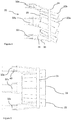
- Figure 7 is a rear view of the variable geometry exhaust nozzle of figure 2 in a fifth position.
- a gas turbine engine is generally indicated at 10, having a principal and rotational axis 11.
- the engine 10 comprises, in axial flow series, an air intake 12, a propulsive fan 13, an intermediate pressure compressor 14, a high-pressure compressor 15, combustion equipment 16, a high-pressure turbine 17, an intermediate pressure turbine 18, a low-pressure turbine 19 and an exhaust nozzle arrangement 20.
- a nacelle 21 generally surrounds the engine 10 and defines both the intake 12 and the exhaust nozzle arrangement 20.
- the gas turbine engine 10 works in the conventional manner so that air entering the intake 12 is accelerated by the fan 13 to produce two air flows: a first air flow into the intermediate pressure compressor 14 and a second air flow which passes through a bypass duct 23 to provide propulsive thrust.
- the intermediate pressure compressor 14 compresses the air flow directed into it before delivering that air to the high pressure compressor 15 where further compression takes place.
- the compressed air exhausted from the high-pressure compressor 15 is directed into the combustion equipment 16 where it is mixed with fuel and the mixture combusted.
- the resultant hot combustion products then expand through, and thereby drive the high, intermediate and low-pressure turbines 17, 18, 19 before being exhausted through the nozzle arrangement 20 to provide additional propulsive thrust.
- the high 17, intermediate 18 and low 19 pressure turbines drive respectively the high pressure compressor 15, intermediate pressure compressor 14 and fan 13, each by suitable interconnecting shaft.
- the nozzle arrangement 20 is shown in more detail in a first position in figures 2 and 3 .
- the arrangement comprises a plurality of petals 23, which project in a generally longitudinal direction X to define the perimeter of an annular duct through which gas turbine exhaust flows in use.
- Each petal 22 overlaps slightly with an adjacent petal 22 in order to minimise gaps therebetween, whilst permitting relative movement.
- the petals 22 comprise radially inner “slave” petals 22a, and radially outer “master” petals 22b.
- the outer petals 22b overlap adjacent inner petals 22a, with the inner and outer petals 22a, 22b being arranged in an alternating fashion. Only the outer master petals are directly mounted to the ring 24 by the guide rails 30, such that movement of the outer petals 22b drives movement of the inner petals 22a, while allowing sliding movement therebetween.
- Each petal is mounted by a hinge 25 at an upstream 26 end, which permits each petal to pivot about a generally circumferential axis, such that a downstream end 22 of each petal is moveable in a generally radial direction.
- each petal widens in a generally circumferential direction from an upstream to a downstream end.
- Upstream of the hinge 25 may be a convergent nozzle section (not shown), which is configured to accelerate gas turbine engine exhaust to sonic or supersonic speeds.
- the petals are provided at a downstream end of the engine, such that exhaust flows out of the duct defined by the petals to ambient air. Therefore it will be understood that the positioning of the petals 22 will define both the duct final area, and the vector of thrust exiting the nozzle 20, and therefore will define the expansion ratio of the nozzle, and the thrust vector.
- the nozzle arrangement 20 further comprises an annular ring 24 provided annularly outward of, and surrounding the petals 22.
- a diameter of the ring 24 extends in a direction parallel to a radial plane of the engine, i.e. normal to the longitudinal axis X.
- the ring 24 in this embodiment has a larger inner diameter than the outer diameter of the upstream end 26 of the duct. It will be understood however that embodiments in which the ring 24 has a smaller diameter than the upstream end of the duct are envisaged.
- the annular ring 24 slidably engages against an outer surface of at least a subset of the petals 22, and in this case to the radially outer petals 22.
- the ring 24 pivotably and slidably engages with each petal 22 by a guide rail 30, such that the ring 24 can move in a direction generally parallel to the engine longitudinal axis X, with the petals being urged inwardly by longitudinal movement of the ring 24, and outwardly by duct pressure.
- Other mounting arrangements could be envisaged, provided that longitudinal translation of the ring 24 causes radial movement of the petals 22.
- the annular ring 24 is translatable by a plurality of (three in this embodiment) actuator arrangements 32a, 32b, 32c.
- Each actuator arrangement 32a-c comprises first and second circumferentially spaced actuator arms 34, 36, which are pivotably mounted at a first, downstream end to the ring 24, and at a second, upstream end to a slide arrangement 38 at an upstream end.
- Each of the arms 34, 36 is mounted with fixed spacing spacing between the first and second arms 34, 36, that each of the arms 34, 36 are parallel to the other of that arrangement 32a-c, such that the arms 34, 36 pivot in unison.
- Each of the arms 34, 36 of each actuator arrangement 32a-c is also of the same length.
- the slide arrangement 38 comprises a shuttle 40 slidably mounted to one or more rails 42.
- the rails are generally parallel to the engine longitudinal axis X, such that the shuttle 40 is slidably moveable along the axis X.
- One or more hydraulic actuators 44 are provided for axially moving a respective shuttle 40 in the axial direction X (only one of which is shown for clarity).
- Each hydraulic actuator 44 is controlled by a controller 46, which can provide for independent or collective actuation of the actuators 44, as will be described in further detail below.
- Figure 5 shows the nozzle arrangement 20 in a second position.
- the shuttles 40 of the actuator arrangements 32a-c have been urged axially rearwardly (i.e. in a downstream direction) from their positions shown in figure 2 .
- the longitudinal distance each shuttle 40 has been moved between the first and second positions is substantially equal, and so the actuator arrangements 32a-c can be said to have been moved collectively or synchronously.
- each of the pairs of actuator arms 34, 36 is moved axially, whilst also pivoting relative to the shuttle and the ring 24, to maintain their parallelism. Consequently, the ring 24 is slid rearwardly along the rails 30 in the downstream direction, while maintaining the same orientation (i.e.
- the ring 24 does not tilt / pivot / gimbal away from a radial plane).
- the downstream end of the petals are urged inwardly, thereby reducing the divergence of the duct, and so the final area of the nozzle 20. Since the ring 24 maintains its radial orientation, the petals 22 are each urged inwardly to the same extent, such that gaps do not appear between the petals in either the first or second position.
- figure 6 shows the nozzle arrangement in a third position, in which the shuttles 40 of the actuator arrangements 32a-c have been urged axially rearwardly (i.e. in a downstream direction) from their positions shown in figure 2 .
- the ring 24 is moved axially forwardly, thereby urging the petals 22 outwardly, to increase the divergence of the nozzle, and so increase the final area.
- Figure 4 shows the nozzle arrangement 20 in a fourth position corresponding to a downward vectored thrust nozzle position.
- the petals 22 are oriented toward the ground when the aircraft is in level flight, to provide either a downward pitching moment, or to increase lift to assist with takeoff.
- the controller 46 controls each of the actuator arrangement 32a-c independently, i.e. asynchronously.
- the actuator arrangement 32a closest to top dead centre of the engine is moved rearwardly parallel to the longitudinal direction X.
- the actuator arrangement 32b located at a mid-location is moved rearwardly to a lesser extent.
- the actuator arrangement 32c is moved forwardly somewhat, then rearwardly, though to a less extent than the actuator arrangement 32a. Consequently, the arms 34, 36 the upstream end of the first and second arms 34, 36 of the first actuator arrangement 32a are moved axially rearwardly, and are pivoted, whereas the downstream ends are pivoted relative to the ring 24, while staying the same axial position.
- the arms 32, 34 of the other actuator arrangements move in a similar fashion, with their downstream ends pivoting and moving downwardly, whilst remaining in the same longitudinal position. Consequently, the ring 24 is moved downwardly in a direction normal to the engine longitudinal axis X, whilst again remaining in the same orientation, such that the centre of the ring 24 is no longer coaxial with the centreline of the engine 10.
- the petals 22 are pivotably mounted to the ring 24 at a point downstream of the hinges, the petals 22 are pivoted about their respective hinges 26, and so re-oriented in a downward direction by the lateral movement of the ring 24. Consequently, thrust from the nozzle 20 is vectored downwardly in the fourth position.
- the petals 22 are moved evenly. Consequently, gaps between the petals 22 do not open up when the nozzle is moved from the first to the third position. It will be understood that the nozzle 20 can be moved to an upward thrust vectoring position in a similar manner, or in a port or starboard orientation using differential movement of the actuator arrangements 32a-c. Similarly, the actuators 32a-c can be moved both collectively and differentially to both adjust the final area and the nozzle vector simultaneously.
- figure 7 shows the nozzle arrangement 20 in a fifth position corresponding to a laterally vectored thrust nozzle position.
- the petals 22 are oriented toward the port side when the aircraft is in level flight, to provide either a lateral force to assist with aircraft manoeuvres, by providing a yaw moment.
- the actuator arrangements 32a-c are move asynchronously, with the shuttle 40 of the second actuator arrangement 32b being moved forward, while the shuttles of the first and third actuator arrangements are moved rearward. Consequently, the centre of the ring 24 is moved to one side of the engine longitudinal axis, thereby vectoring the thrust to one side, off the engine axis. It will be understood that similar movement in the opposite direction will provide yawing in the opposite direction. Similarly, it will be understood that a combination of these movements can provide both final area adjustment and nozzle vector adjustment simultaneously.
- gas turbine engines to which the present disclosure may be applied may have alternative configurations.
- such engines may have an alternative number of interconnecting shafts (e.g. two) and/or an alternative number of compressors and/or turbines.
- the engine may comprise a gearbox provided in the drive train from a turbine to a compressor and/or fan.
- the fan may be omitted, with all flow passing through the compressors.
- Such an arrangement is known as a "turbojet”.
- the engine may comprise a "low bypass" turbofan, comprising a multi-stage, high pressure ratio fan, which passes a greater portion of flow to the compressors than in the case of a high bypass ratio, single stage fan design.
- the actuators may be hydraulically, electrically, or pneumatically driven.
Landscapes
- Engineering & Computer Science (AREA)
- Chemical & Material Sciences (AREA)
- Combustion & Propulsion (AREA)
- Mechanical Engineering (AREA)
- General Engineering & Computer Science (AREA)
- Control Of Turbines (AREA)
- Supercharger (AREA)
Abstract
Description
- The present disclosure concerns a nozzle such as a gas turbine engine nozzle which can provide thrust vectoring in flight.
- In order to increase aircraft manoeuvrability, it is known to provide aircraft having vectorable exhaust nozzles, so that exhaust from the engine can be directed in a desired direction. Prior designs are known which comprise a plurality of hinged petals, positioned by a series of linkages. The linkages are in turn mounted to a gimballed ring, controlled by actuators. Such an arrangement is sometimes referred to as an "iris" design, and may permit both thrust vectoring and exhaust nozzle area adjustment. An example prior design is disclosed in
US 4994660 . Vectoring nozzles are also known for directing aircraft exhausts for providing vertical / short takeoff and landing (V/STOL). An example prior V/STOL vectoring nozzle is described inUS 3429509 , which uses a three-bearing swivel nozzle. - Prior "petal" type vectorable exhaust nozzles controlled by a gimballing ring allow gaps to form between petals during movement, since the linkage arrangement is unable to evenly distribute the petals. Some designs use an additional link to reduce this effect. However, significant petal gaps still form. On the other hand, three-bearing swivel nozzles can provide for exhaust vectoring, but separate provision must be made for exhaust nozzle area modulation, and vectoring can only generally be provided for in one axis.
- Similar considerations apply for pump jets, where smaller nozzle areas are desirable to provide for high acceleration and larger areas for efficient cruising, while thrust vectoring is desirable to provide steering. Again, conventional vectorable designs may suffer from similar disadvantages as the above jet engine nozzle designs.
- Where gaps form in the nozzle, additional cooling air is required, reducing the performance of the engine. In addition the nozzle has greater losses and is less effective.
- According to a first aspect there is provided a variable geometry exhaust nozzle arrangement comprising:
- a plurality of hingeable exhaust petals defining a perimeter of an exhaust duct;
- an annular ring slidably engagable against a radially outer surface of each petal;
- the annular ring being coupled to a plurality of circumferentially spaced actuator assemblies;
- each actuator arrangement comprising first and second circumferentially spaced parallel actuator arms pivotably coupled to the annular ring at a first end and to a slide arrangement at a second end;
- each slide arrangement being mounted for linear sliding movement relative to the annular ring, such that sliding movement of each slide arrangement causes pivoting of the first and second actuator arms to thereby translate the annular ring in one or both of a longitudinal direction and a lateral direction.
- Advantageously, the arrangement of the present disclosure provides for both variable exhaust area and variable exhaust vectoring by translating the annular ring in a longitudinal direction and a lateral direction respectively. Since the ring is mounted for substantially translating movement only (and not gimballing movement), gaps are not formed between the petals at any exhaust nozzle position, thereby reducing the requirement for cooling air, and increasing propulsive performance. Furthermore, fewer petals may be required in view of the relatively constant gap / overlap between petals at different nozzle positions, thereby reducing weight, complexity, part count and cost.
- The exhaust nozzle arrangement may comprise two actuator assemblies spaced approximately 180° from one another. Such an arrangement provides for both exhaust nozzle area adjustment and thrust vector control in one axis. The nozzle may comprise three or more actuator assemblies. Such an arrangement provides for both exhaust nozzle area adjustment and thrust vector control in two axes.
- Each slide arrangement may be independently actuable by a respective actuator. Each actuator arrangement may comprise one or more of a linear motor, hydraulic actuator and pneumatic actuator.
- The annular ring may be slidably mounted to one of a convergent portion and a divergent portion of the exhaust duct.
- The lengths of the first actuator arms may be substantially equal to one another.
- The exhaust nozzle arrangement may be mounted to one of a gas turbine engine and a pump jet.
- According to a second aspect of the disclosure there is provided an aircraft gas turbine engine comprising an exhaust nozzle arrangement in accordance with the first aspect.
- According to a third aspect of the disclosure there is provided a pump jet comprising an exhaust nozzle arrangement in accordance with the first aspect.
- The skilled person will appreciate that except where mutually exclusive, a feature described in relation to any one of the above aspects may be applied mutatis mutandis to any other aspect. Furthermore except where mutually exclusive any feature described herein may be applied to any aspect and/or combined with any other feature described herein.
- Embodiments will now be described by way of example only, with reference to the Figures, in which:
-
Figure 1 is a sectional side view of a gas turbine engine; -
Figure 2 is a side view of a variable geometry exhaust nozzle of the gas turbine engine offigure 1 in a first position; -
Figure 3 is a rear view of the variable geometry exhaust nozzle offigure 2 ; -
Figure 4 is a side view the variable geometry exhaust nozzle offigure 2 in a fourth position; -
Figure 5 is a side view of the variable geometry exhaust nozzle offigure 2 in a second position; -
Figure 6 is a side view of the variable geometry exhaust nozzle offigure 2 in a third position; and -
Figure 7 is a rear view of the variable geometry exhaust nozzle offigure 2 in a fifth position. - With reference to
Figure 1 , a gas turbine engine is generally indicated at 10, having a principal androtational axis 11. Theengine 10 comprises, in axial flow series, anair intake 12, apropulsive fan 13, anintermediate pressure compressor 14, a high-pressure compressor 15,combustion equipment 16, a high-pressure turbine 17, anintermediate pressure turbine 18, a low-pressure turbine 19 and anexhaust nozzle arrangement 20. Anacelle 21 generally surrounds theengine 10 and defines both theintake 12 and theexhaust nozzle arrangement 20. - The
gas turbine engine 10 works in the conventional manner so that air entering theintake 12 is accelerated by thefan 13 to produce two air flows: a first air flow into theintermediate pressure compressor 14 and a second air flow which passes through abypass duct 23 to provide propulsive thrust. Theintermediate pressure compressor 14 compresses the air flow directed into it before delivering that air to thehigh pressure compressor 15 where further compression takes place. - The compressed air exhausted from the high-
pressure compressor 15 is directed into thecombustion equipment 16 where it is mixed with fuel and the mixture combusted. The resultant hot combustion products then expand through, and thereby drive the high, intermediate and low-pressure turbines nozzle arrangement 20 to provide additional propulsive thrust. The high 17, intermediate 18 and low 19 pressure turbines drive respectively thehigh pressure compressor 15,intermediate pressure compressor 14 andfan 13, each by suitable interconnecting shaft. - The
nozzle arrangement 20 is shown in more detail in a first position infigures 2 and3 . The arrangement comprises a plurality ofpetals 23, which project in a generally longitudinal direction X to define the perimeter of an annular duct through which gas turbine exhaust flows in use. Eachpetal 22 overlaps slightly with anadjacent petal 22 in order to minimise gaps therebetween, whilst permitting relative movement. Thepetals 22 comprise radially inner "slave"petals 22a, and radially outer "master"petals 22b. Theouter petals 22b overlap adjacentinner petals 22a, with the inner andouter petals ring 24 by theguide rails 30, such that movement of theouter petals 22b drives movement of theinner petals 22a, while allowing sliding movement therebetween. - Each petal is mounted by a
hinge 25 at an upstream 26 end, which permits each petal to pivot about a generally circumferential axis, such that adownstream end 22 of each petal is moveable in a generally radial direction. Typically, each petal widens in a generally circumferential direction from an upstream to a downstream end. Upstream of thehinge 25 may be a convergent nozzle section (not shown), which is configured to accelerate gas turbine engine exhaust to sonic or supersonic speeds. The petals are provided at a downstream end of the engine, such that exhaust flows out of the duct defined by the petals to ambient air. Therefore it will be understood that the positioning of thepetals 22 will define both the duct final area, and the vector of thrust exiting thenozzle 20, and therefore will define the expansion ratio of the nozzle, and the thrust vector. - The
nozzle arrangement 20 further comprises anannular ring 24 provided annularly outward of, and surrounding thepetals 22. A diameter of thering 24 extends in a direction parallel to a radial plane of the engine, i.e. normal to the longitudinal axis X. Thering 24 in this embodiment has a larger inner diameter than the outer diameter of theupstream end 26 of the duct. It will be understood however that embodiments in which thering 24 has a smaller diameter than the upstream end of the duct are envisaged. - The
annular ring 24 slidably engages against an outer surface of at least a subset of thepetals 22, and in this case to the radiallyouter petals 22. In this embodiment, thering 24 pivotably and slidably engages with eachpetal 22 by aguide rail 30, such that thering 24 can move in a direction generally parallel to the engine longitudinal axis X, with the petals being urged inwardly by longitudinal movement of thering 24, and outwardly by duct pressure. Other mounting arrangements could be envisaged, provided that longitudinal translation of thering 24 causes radial movement of thepetals 22. Since the inner diameter of thering 24 is greater than the outer diameter of the duct at theupstream end 26, axial translation in a downstream direction causes the petals to move inwardly, thereby reducing nozzle final area, while axial translation in an upstream direction causes the petals to move radially outwardly, thereby increasing nozzle final area. - The
annular ring 24 is translatable by a plurality of (three in this embodiment)actuator arrangements actuator arrangement 32a-c comprises first and second circumferentially spacedactuator arms ring 24, and at a second, upstream end to aslide arrangement 38 at an upstream end. Each of thearms second arms arms arrangement 32a-c, such that thearms arms actuator arrangement 32a-c is also of the same length. - The
slide arrangement 38 comprises ashuttle 40 slidably mounted to one or more rails 42. The rails are generally parallel to the engine longitudinal axis X, such that theshuttle 40 is slidably moveable along the axis X. One or morehydraulic actuators 44 are provided for axially moving arespective shuttle 40 in the axial direction X (only one of which is shown for clarity). Eachhydraulic actuator 44 is controlled by acontroller 46, which can provide for independent or collective actuation of theactuators 44, as will be described in further detail below. -
Figure 5 shows thenozzle arrangement 20 in a second position. Theshuttles 40 of theactuator arrangements 32a-c have been urged axially rearwardly (i.e. in a downstream direction) from their positions shown infigure 2 . The longitudinal distance eachshuttle 40 has been moved between the first and second positions is substantially equal, and so theactuator arrangements 32a-c can be said to have been moved collectively or synchronously. As a consequence, each of the pairs ofactuator arms ring 24, to maintain their parallelism. Consequently, thering 24 is slid rearwardly along therails 30 in the downstream direction, while maintaining the same orientation (i.e. thering 24 does not tilt / pivot / gimbal away from a radial plane). In view of the smaller inner diameter of thering 24 relative to theupstream end 26 of thepetals 22, and the engagement of thering 24 against thepetals 22, the downstream end of the petals are urged inwardly, thereby reducing the divergence of the duct, and so the final area of thenozzle 20. Since thering 24 maintains its radial orientation, thepetals 22 are each urged inwardly to the same extent, such that gaps do not appear between the petals in either the first or second position. - Similarly,
figure 6 shows the nozzle arrangement in a third position, in which theshuttles 40 of theactuator arrangements 32a-c have been urged axially rearwardly (i.e. in a downstream direction) from their positions shown infigure 2 . In this case, thering 24 is moved axially forwardly, thereby urging thepetals 22 outwardly, to increase the divergence of the nozzle, and so increase the final area. -
Figure 4 shows thenozzle arrangement 20 in a fourth position corresponding to a downward vectored thrust nozzle position. In this position, thepetals 22 are oriented toward the ground when the aircraft is in level flight, to provide either a downward pitching moment, or to increase lift to assist with takeoff. - In moving the
nozzle arrangement 20 from the first position to the fourth position, thecontroller 46 controls each of theactuator arrangement 32a-c independently, i.e. asynchronously. In this case, theactuator arrangement 32a closest to top dead centre of the engine is moved rearwardly parallel to the longitudinal direction X. Theactuator arrangement 32b located at a mid-location is moved rearwardly to a lesser extent. Theactuator arrangement 32c is moved forwardly somewhat, then rearwardly, though to a less extent than theactuator arrangement 32a. Consequently, thearms second arms first actuator arrangement 32a are moved axially rearwardly, and are pivoted, whereas the downstream ends are pivoted relative to thering 24, while staying the same axial position. Similarly, thearms 32, 34 of the other actuator arrangements move in a similar fashion, with their downstream ends pivoting and moving downwardly, whilst remaining in the same longitudinal position. Consequently, thering 24 is moved downwardly in a direction normal to the engine longitudinal axis X, whilst again remaining in the same orientation, such that the centre of thering 24 is no longer coaxial with the centreline of theengine 10. - Since the
petals 22 are pivotably mounted to thering 24 at a point downstream of the hinges, thepetals 22 are pivoted about theirrespective hinges 26, and so re-oriented in a downward direction by the lateral movement of thering 24. Consequently, thrust from thenozzle 20 is vectored downwardly in the fourth position. - Since the
ring 24 moves laterally while maintaining an orientation in a radial plane, thepetals 22 are moved evenly. Consequently, gaps between thepetals 22 do not open up when the nozzle is moved from the first to the third position. It will be understood that thenozzle 20 can be moved to an upward thrust vectoring position in a similar manner, or in a port or starboard orientation using differential movement of theactuator arrangements 32a-c. Similarly, theactuators 32a-c can be moved both collectively and differentially to both adjust the final area and the nozzle vector simultaneously. - Similarly,
figure 7 shows thenozzle arrangement 20 in a fifth position corresponding to a laterally vectored thrust nozzle position. In this position, thepetals 22 are oriented toward the port side when the aircraft is in level flight, to provide either a lateral force to assist with aircraft manoeuvres, by providing a yaw moment. - Again, the
actuator arrangements 32a-c are move asynchronously, with theshuttle 40 of thesecond actuator arrangement 32b being moved forward, while the shuttles of the first and third actuator arrangements are moved rearward. Consequently, the centre of thering 24 is moved to one side of the engine longitudinal axis, thereby vectoring the thrust to one side, off the engine axis. It will be understood that similar movement in the opposite direction will provide yawing in the opposite direction. Similarly, it will be understood that a combination of these movements can provide both final area adjustment and nozzle vector adjustment simultaneously. - It will be understood that the invention is not limited to the embodiments above-described and various modifications and improvements can be made without departing from the concepts described herein. Except where mutually exclusive, any of the features may be employed separately or in combination with any other features and the disclosure extends to and includes all combinations and subcombinations of one or more features described herein.
- For example, other gas turbine engines to which the present disclosure may be applied may have alternative configurations. By way of example such engines may have an alternative number of interconnecting shafts (e.g. two) and/or an alternative number of compressors and/or turbines. Further the engine may comprise a gearbox provided in the drive train from a turbine to a compressor and/or fan. Similarly, the fan may be omitted, with all flow passing through the compressors. Such an arrangement is known as a "turbojet". Alternatively, the engine may comprise a "low bypass" turbofan, comprising a multi-stage, high pressure ratio fan, which passes a greater portion of flow to the compressors than in the case of a high bypass ratio, single stage fan design.
- As a further example, the actuators may be hydraulically, electrically, or pneumatically driven.
Claims (10)
- A variable geometry exhaust nozzle arrangement (20) comprising:a plurality of hingeable exhaust petals (22) defining a perimeter of an exhaust duct (21);an annular ring (24) slidably engagable against a radially outer surface of each petal (22);the annular ring (24) being coupled to a plurality of circumferentially spaced actuator assemblies (32);each actuator arrangement comprising first and second circumferentially spaced parallel actuator arms (34, 36) pivotably coupled to the annular ring (24) at a first end and to a slide arrangement (38) at a second end;each slide arrangement (38) being mounted for linear sliding movement relative to the annular ring (24), such that sliding movement of each slide arrangement (38) causes pivoting of the first and second actuator arms (34, 36) to thereby translate the annular ring (24) in one or both of a longitudinal direction and a lateral direction.
- An arrangement according to claim 1 comprising two actuator assemblies spaced approximately 180° from one another.
- An arrangement according to claim 2 comprising three or more actuator assemblies.
- An arrangement according to any of the preceding claims, wherein each slide arrangement is independently actuable by a respective actuator.
- An arrangement according to any of the preceding claims, wherein each actuator arrangement comprises one or more of a linear motor, hydraulic actuator and pneumatic actuator.
- An arrangement according to any of the preceding claims, wherein the annular ring is slidably mounted to one of a convergent portion and a divergent portion of the exhaust duct.
- An arrangement according to any of the preceding claims, wherein the lengths of the first actuator arms may be substantially equal to one another.
- An arrangement according to any of the preceding claims, wherein the exhaust nozzle arrangement is mounted to one of a gas turbine engine and a pump jet.
- An aircraft gas turbine engine comprising an exhaust nozzle arrangement in accordance with any of the preceding claims.
- A pump jet comprising an exhaust nozzle arrangement in accordance with any of claims 1 to 8.
Applications Claiming Priority (1)
| Application Number | Priority Date | Filing Date | Title |
|---|---|---|---|
| GBGB1618339.4A GB201618339D0 (en) | 2016-10-31 | 2016-10-31 | Thrust vectoring nozzle |
Publications (2)
| Publication Number | Publication Date |
|---|---|
| EP3315753A1 true EP3315753A1 (en) | 2018-05-02 |
| EP3315753B1 EP3315753B1 (en) | 2019-08-21 |
Family
ID=57963774
Family Applications (1)
| Application Number | Title | Priority Date | Filing Date |
|---|---|---|---|
| EP17194709.6A Active EP3315753B1 (en) | 2016-10-31 | 2017-10-04 | Thrust vectoring nozzle |
Country Status (3)
| Country | Link |
|---|---|
| US (1) | US10385805B2 (en) |
| EP (1) | EP3315753B1 (en) |
| GB (1) | GB201618339D0 (en) |
Cited By (3)
| Publication number | Priority date | Publication date | Assignee | Title |
|---|---|---|---|---|
| CN115077839A (en) * | 2022-06-08 | 2022-09-20 | 东北大学 | Dynamic loading device for vector deflection aerodynamic force simulation of vectoring nozzle expansion sheet |
| CN115163328A (en) * | 2022-04-24 | 2022-10-11 | 中国航发四川燃气涡轮研究院 | Improved external adjusting structure for binary vector nozzle |
| CN116202774A (en) * | 2023-04-28 | 2023-06-02 | 中国航发四川燃气涡轮研究院 | Exhaust full-containment structure for high-altitude bench vector test |
Families Citing this family (1)
| Publication number | Priority date | Publication date | Assignee | Title |
|---|---|---|---|---|
| US20230021836A1 (en) * | 2021-07-22 | 2023-01-26 | General Electric Company | Unducted thrust producing system |
Citations (4)
| Publication number | Priority date | Publication date | Assignee | Title |
|---|---|---|---|---|
| US3429509A (en) | 1967-05-31 | 1969-02-25 | United Aircraft Corp | Cooling scheme for a three bearing swivel nozzle |
| US4994660A (en) | 1989-04-11 | 1991-02-19 | Hitachi, Ltd. | Axisymmetric vectoring exhaust nozzle |
| US5261605A (en) * | 1990-08-23 | 1993-11-16 | United Technologies Corporation | Axisymmetric nozzle with gimbled unison ring |
| US5437411A (en) * | 1992-12-14 | 1995-08-01 | General Electric Company | Vectoring exhaust nozzle flap and seal positioning apparatus |
Family Cites Families (10)
| Publication number | Priority date | Publication date | Assignee | Title |
|---|---|---|---|---|
| US2693078A (en) * | 1949-03-18 | 1954-11-02 | Westinghouse Electric Corp | Exhaust orifice control for jet engines |
| US5174502A (en) | 1991-05-10 | 1992-12-29 | General Electric Company | Support for a translating nozzle vectoring ring |
| US5238189A (en) * | 1992-07-16 | 1993-08-24 | United Technologies Corporation | Convergent-to-divergent seal hinge for a convergent/divergent nozzle |
| US5267436A (en) * | 1992-09-28 | 1993-12-07 | United Technologies Corporation | Vectoring nozzle control of gas turbine engines |
| IL115248A (en) * | 1994-09-29 | 2000-07-16 | Gen Electric | Hydraulic failsafe system and method for an axisymmetric vectoring nozzle |
| FR2790791B1 (en) | 1999-03-10 | 2001-04-13 | Snecma | EJECTION NOZZLE OF AXISYMMETRIC TURBOREACTOR WITH GLOBAL ORIENTATION |
| WO2008045062A1 (en) | 2006-10-12 | 2008-04-17 | United Technologies Corporation | Fan variable area nozzle for a gas turbine engine fan nacelle with sliding actuation system |
| JP5673405B2 (en) | 2011-07-12 | 2015-02-18 | 株式会社Ihi | Variable exhaust nozzle for jet engine |
| US9341140B2 (en) * | 2012-02-09 | 2016-05-17 | The Boeing Company | Variable area mechanism with angular trailing edges |
| US9650991B2 (en) | 2013-06-27 | 2017-05-16 | The Boeing Company | Pivoting ring petal actuation for variable area fan nozzle |
-
2016
- 2016-10-31 GB GBGB1618339.4A patent/GB201618339D0/en not_active Ceased
-
2017
- 2017-10-04 US US15/725,238 patent/US10385805B2/en active Active
- 2017-10-04 EP EP17194709.6A patent/EP3315753B1/en active Active
Patent Citations (4)
| Publication number | Priority date | Publication date | Assignee | Title |
|---|---|---|---|---|
| US3429509A (en) | 1967-05-31 | 1969-02-25 | United Aircraft Corp | Cooling scheme for a three bearing swivel nozzle |
| US4994660A (en) | 1989-04-11 | 1991-02-19 | Hitachi, Ltd. | Axisymmetric vectoring exhaust nozzle |
| US5261605A (en) * | 1990-08-23 | 1993-11-16 | United Technologies Corporation | Axisymmetric nozzle with gimbled unison ring |
| US5437411A (en) * | 1992-12-14 | 1995-08-01 | General Electric Company | Vectoring exhaust nozzle flap and seal positioning apparatus |
Cited By (4)
| Publication number | Priority date | Publication date | Assignee | Title |
|---|---|---|---|---|
| CN115163328A (en) * | 2022-04-24 | 2022-10-11 | 中国航发四川燃气涡轮研究院 | Improved external adjusting structure for binary vector nozzle |
| CN115077839A (en) * | 2022-06-08 | 2022-09-20 | 东北大学 | Dynamic loading device for vector deflection aerodynamic force simulation of vectoring nozzle expansion sheet |
| CN116202774A (en) * | 2023-04-28 | 2023-06-02 | 中国航发四川燃气涡轮研究院 | Exhaust full-containment structure for high-altitude bench vector test |
| CN116202774B (en) * | 2023-04-28 | 2023-08-18 | 中国航发四川燃气涡轮研究院 | Exhaust full-containment structure for high-altitude bench vector test |
Also Published As
| Publication number | Publication date |
|---|---|
| GB201618339D0 (en) | 2016-12-14 |
| EP3315753B1 (en) | 2019-08-21 |
| US20180119641A1 (en) | 2018-05-03 |
| US10385805B2 (en) | 2019-08-20 |
Similar Documents
| Publication | Publication Date | Title |
|---|---|---|
| US8615980B2 (en) | Gas turbine engine with noise attenuating variable area fan nozzle | |
| US10385805B2 (en) | Thrust vectoring nozzle | |
| US8769925B2 (en) | Thrust vectorable fan variable area nozzle for a gas turbine engine fan nacelle | |
| US8061119B2 (en) | Actuation mechanism for a convertible gas turbine propulsion system | |
| EP2578864B1 (en) | Variable area fan nozzle with bypass flow | |
| US6938408B2 (en) | Thrust vectoring and variable exhaust area for jet engine nozzle | |
| EP2074312B1 (en) | Fan variable area nozzle for a gas turbine engine fan nacelle with sliding actuation system | |
| EP3825538B1 (en) | Variable area fan nozzle bearing track | |
| US5054285A (en) | Thrust reverser for turbofan engine | |
| EP3023623B1 (en) | Gas turbine engine with thrust reversal and method of assembling the same | |
| US20090053058A1 (en) | Gas turbine engine with axial movable fan variable area nozzle | |
| EP3816424B1 (en) | An exhaust nozzle for a gas turbine engine | |
| EP3816425B1 (en) | An exhaust nozzle for a gas turbine engine | |
| US11286878B2 (en) | Variable area nozzle exhaust system with integrated thrust reverser | |
| US5740988A (en) | Axisymmetric vectoring nozzle actuating system having multiple power control circuits | |
| EP3495650B1 (en) | Method of varying an annular fan exit area of a gas turbine engine | |
| EP2971728B1 (en) | Twin target thrust reverser module | |
| EP0091786A1 (en) | Variable geometry nozzles for turbomachines | |
| US11585280B2 (en) | Aircraft and method of operating same | |
| US20230258147A1 (en) | Thrust reverser having three gates | |
| GB2143483A (en) | Compound helicopter and powerplant therefor |
Legal Events
| Date | Code | Title | Description |
|---|---|---|---|
| PUAI | Public reference made under article 153(3) epc to a published international application that has entered the european phase |
Free format text: ORIGINAL CODE: 0009012 |
|
| STAA | Information on the status of an ep patent application or granted ep patent |
Free format text: STATUS: THE APPLICATION HAS BEEN PUBLISHED |
|
| AK | Designated contracting states |
Kind code of ref document: A1 Designated state(s): AL AT BE BG CH CY CZ DE DK EE ES FI FR GB GR HR HU IE IS IT LI LT LU LV MC MK MT NL NO PL PT RO RS SE SI SK SM TR |
|
| AX | Request for extension of the european patent |
Extension state: BA ME |
|
| STAA | Information on the status of an ep patent application or granted ep patent |
Free format text: STATUS: REQUEST FOR EXAMINATION WAS MADE |
|
| 17P | Request for examination filed |
Effective date: 20180514 |
|
| RBV | Designated contracting states (corrected) |
Designated state(s): AL AT BE BG CH CY CZ DE DK EE ES FI FR GB GR HR HU IE IS IT LI LT LU LV MC MK MT NL NO PL PT RO RS SE SI SK SM TR |
|
| STAA | Information on the status of an ep patent application or granted ep patent |
Free format text: STATUS: EXAMINATION IS IN PROGRESS |
|
| 17Q | First examination report despatched |
Effective date: 20181121 |
|
| GRAP | Despatch of communication of intention to grant a patent |
Free format text: ORIGINAL CODE: EPIDOSNIGR1 |
|
| STAA | Information on the status of an ep patent application or granted ep patent |
Free format text: STATUS: GRANT OF PATENT IS INTENDED |
|
| INTG | Intention to grant announced |
Effective date: 20190506 |
|
| GRAS | Grant fee paid |
Free format text: ORIGINAL CODE: EPIDOSNIGR3 |
|
| GRAA | (expected) grant |
Free format text: ORIGINAL CODE: 0009210 |
|
| STAA | Information on the status of an ep patent application or granted ep patent |
Free format text: STATUS: THE PATENT HAS BEEN GRANTED |
|
| AK | Designated contracting states |
Kind code of ref document: B1 Designated state(s): AL AT BE BG CH CY CZ DE DK EE ES FI FR GB GR HR HU IE IS IT LI LT LU LV MC MK MT NL NO PL PT RO RS SE SI SK SM TR |
|
| REG | Reference to a national code |
Ref country code: GB Ref legal event code: FG4D |
|
| REG | Reference to a national code |
Ref country code: CH Ref legal event code: EP |
|
| REG | Reference to a national code |
Ref country code: DE Ref legal event code: R096 Ref document number: 602017006315 Country of ref document: DE |
|
| REG | Reference to a national code |
Ref country code: AT Ref legal event code: REF Ref document number: 1170039 Country of ref document: AT Kind code of ref document: T Effective date: 20190915 |
|
| REG | Reference to a national code |
Ref country code: IE Ref legal event code: FG4D |
|
| REG | Reference to a national code |
Ref country code: LT Ref legal event code: MG4D |
|
| REG | Reference to a national code |
Ref country code: NL Ref legal event code: MP Effective date: 20190821 |
|
| PG25 | Lapsed in a contracting state [announced via postgrant information from national office to epo] |
Ref country code: SE Free format text: LAPSE BECAUSE OF FAILURE TO SUBMIT A TRANSLATION OF THE DESCRIPTION OR TO PAY THE FEE WITHIN THE PRESCRIBED TIME-LIMIT Effective date: 20190821 Ref country code: BG Free format text: LAPSE BECAUSE OF FAILURE TO SUBMIT A TRANSLATION OF THE DESCRIPTION OR TO PAY THE FEE WITHIN THE PRESCRIBED TIME-LIMIT Effective date: 20191121 Ref country code: NL Free format text: LAPSE BECAUSE OF FAILURE TO SUBMIT A TRANSLATION OF THE DESCRIPTION OR TO PAY THE FEE WITHIN THE PRESCRIBED TIME-LIMIT Effective date: 20190821 Ref country code: HR Free format text: LAPSE BECAUSE OF FAILURE TO SUBMIT A TRANSLATION OF THE DESCRIPTION OR TO PAY THE FEE WITHIN THE PRESCRIBED TIME-LIMIT Effective date: 20190821 Ref country code: NO Free format text: LAPSE BECAUSE OF FAILURE TO SUBMIT A TRANSLATION OF THE DESCRIPTION OR TO PAY THE FEE WITHIN THE PRESCRIBED TIME-LIMIT Effective date: 20191121 Ref country code: LT Free format text: LAPSE BECAUSE OF FAILURE TO SUBMIT A TRANSLATION OF THE DESCRIPTION OR TO PAY THE FEE WITHIN THE PRESCRIBED TIME-LIMIT Effective date: 20190821 Ref country code: PT Free format text: LAPSE BECAUSE OF FAILURE TO SUBMIT A TRANSLATION OF THE DESCRIPTION OR TO PAY THE FEE WITHIN THE PRESCRIBED TIME-LIMIT Effective date: 20191223 Ref country code: FI Free format text: LAPSE BECAUSE OF FAILURE TO SUBMIT A TRANSLATION OF THE DESCRIPTION OR TO PAY THE FEE WITHIN THE PRESCRIBED TIME-LIMIT Effective date: 20190821 |
|
| RAP2 | Party data changed (patent owner data changed or rights of a patent transferred) |
Owner name: ROLLS-ROYCE PLC |
|
| PG25 | Lapsed in a contracting state [announced via postgrant information from national office to epo] |
Ref country code: LV Free format text: LAPSE BECAUSE OF FAILURE TO SUBMIT A TRANSLATION OF THE DESCRIPTION OR TO PAY THE FEE WITHIN THE PRESCRIBED TIME-LIMIT Effective date: 20190821 Ref country code: GR Free format text: LAPSE BECAUSE OF FAILURE TO SUBMIT A TRANSLATION OF THE DESCRIPTION OR TO PAY THE FEE WITHIN THE PRESCRIBED TIME-LIMIT Effective date: 20191122 Ref country code: ES Free format text: LAPSE BECAUSE OF FAILURE TO SUBMIT A TRANSLATION OF THE DESCRIPTION OR TO PAY THE FEE WITHIN THE PRESCRIBED TIME-LIMIT Effective date: 20190821 Ref country code: AL Free format text: LAPSE BECAUSE OF FAILURE TO SUBMIT A TRANSLATION OF THE DESCRIPTION OR TO PAY THE FEE WITHIN THE PRESCRIBED TIME-LIMIT Effective date: 20190821 Ref country code: RS Free format text: LAPSE BECAUSE OF FAILURE TO SUBMIT A TRANSLATION OF THE DESCRIPTION OR TO PAY THE FEE WITHIN THE PRESCRIBED TIME-LIMIT Effective date: 20190821 Ref country code: IS Free format text: LAPSE BECAUSE OF FAILURE TO SUBMIT A TRANSLATION OF THE DESCRIPTION OR TO PAY THE FEE WITHIN THE PRESCRIBED TIME-LIMIT Effective date: 20191221 |
|
| REG | Reference to a national code |
Ref country code: AT Ref legal event code: MK05 Ref document number: 1170039 Country of ref document: AT Kind code of ref document: T Effective date: 20190821 |
|
| PG25 | Lapsed in a contracting state [announced via postgrant information from national office to epo] |
Ref country code: TR Free format text: LAPSE BECAUSE OF FAILURE TO SUBMIT A TRANSLATION OF THE DESCRIPTION OR TO PAY THE FEE WITHIN THE PRESCRIBED TIME-LIMIT Effective date: 20190821 |
|
| PG25 | Lapsed in a contracting state [announced via postgrant information from national office to epo] |
Ref country code: AT Free format text: LAPSE BECAUSE OF FAILURE TO SUBMIT A TRANSLATION OF THE DESCRIPTION OR TO PAY THE FEE WITHIN THE PRESCRIBED TIME-LIMIT Effective date: 20190821 Ref country code: EE Free format text: LAPSE BECAUSE OF FAILURE TO SUBMIT A TRANSLATION OF THE DESCRIPTION OR TO PAY THE FEE WITHIN THE PRESCRIBED TIME-LIMIT Effective date: 20190821 Ref country code: IT Free format text: LAPSE BECAUSE OF FAILURE TO SUBMIT A TRANSLATION OF THE DESCRIPTION OR TO PAY THE FEE WITHIN THE PRESCRIBED TIME-LIMIT Effective date: 20190821 Ref country code: DK Free format text: LAPSE BECAUSE OF FAILURE TO SUBMIT A TRANSLATION OF THE DESCRIPTION OR TO PAY THE FEE WITHIN THE PRESCRIBED TIME-LIMIT Effective date: 20190821 Ref country code: RO Free format text: LAPSE BECAUSE OF FAILURE TO SUBMIT A TRANSLATION OF THE DESCRIPTION OR TO PAY THE FEE WITHIN THE PRESCRIBED TIME-LIMIT Effective date: 20190821 Ref country code: PL Free format text: LAPSE BECAUSE OF FAILURE TO SUBMIT A TRANSLATION OF THE DESCRIPTION OR TO PAY THE FEE WITHIN THE PRESCRIBED TIME-LIMIT Effective date: 20190821 |
|
| PG25 | Lapsed in a contracting state [announced via postgrant information from national office to epo] |
Ref country code: IS Free format text: LAPSE BECAUSE OF FAILURE TO SUBMIT A TRANSLATION OF THE DESCRIPTION OR TO PAY THE FEE WITHIN THE PRESCRIBED TIME-LIMIT Effective date: 20200224 Ref country code: MC Free format text: LAPSE BECAUSE OF FAILURE TO SUBMIT A TRANSLATION OF THE DESCRIPTION OR TO PAY THE FEE WITHIN THE PRESCRIBED TIME-LIMIT Effective date: 20190821 Ref country code: SK Free format text: LAPSE BECAUSE OF FAILURE TO SUBMIT A TRANSLATION OF THE DESCRIPTION OR TO PAY THE FEE WITHIN THE PRESCRIBED TIME-LIMIT Effective date: 20190821 Ref country code: CZ Free format text: LAPSE BECAUSE OF FAILURE TO SUBMIT A TRANSLATION OF THE DESCRIPTION OR TO PAY THE FEE WITHIN THE PRESCRIBED TIME-LIMIT Effective date: 20190821 Ref country code: SM Free format text: LAPSE BECAUSE OF FAILURE TO SUBMIT A TRANSLATION OF THE DESCRIPTION OR TO PAY THE FEE WITHIN THE PRESCRIBED TIME-LIMIT Effective date: 20190821 |
|
| REG | Reference to a national code |
Ref country code: DE Ref legal event code: R097 Ref document number: 602017006315 Country of ref document: DE |
|
| PLBE | No opposition filed within time limit |
Free format text: ORIGINAL CODE: 0009261 |
|
| STAA | Information on the status of an ep patent application or granted ep patent |
Free format text: STATUS: NO OPPOSITION FILED WITHIN TIME LIMIT |
|
| PG2D | Information on lapse in contracting state deleted |
Ref country code: IS |
|
| PG25 | Lapsed in a contracting state [announced via postgrant information from national office to epo] |
Ref country code: LU Free format text: LAPSE BECAUSE OF NON-PAYMENT OF DUE FEES Effective date: 20191004 |
|
| 26N | No opposition filed |
Effective date: 20200603 |
|
| REG | Reference to a national code |
Ref country code: BE Ref legal event code: MM Effective date: 20191031 |
|
| PG25 | Lapsed in a contracting state [announced via postgrant information from national office to epo] |
Ref country code: SI Free format text: LAPSE BECAUSE OF FAILURE TO SUBMIT A TRANSLATION OF THE DESCRIPTION OR TO PAY THE FEE WITHIN THE PRESCRIBED TIME-LIMIT Effective date: 20190821 Ref country code: BE Free format text: LAPSE BECAUSE OF NON-PAYMENT OF DUE FEES Effective date: 20191031 |
|
| PG25 | Lapsed in a contracting state [announced via postgrant information from national office to epo] |
Ref country code: IE Free format text: LAPSE BECAUSE OF NON-PAYMENT OF DUE FEES Effective date: 20191004 |
|
| PG25 | Lapsed in a contracting state [announced via postgrant information from national office to epo] |
Ref country code: CY Free format text: LAPSE BECAUSE OF FAILURE TO SUBMIT A TRANSLATION OF THE DESCRIPTION OR TO PAY THE FEE WITHIN THE PRESCRIBED TIME-LIMIT Effective date: 20190821 |
|
| REG | Reference to a national code |
Ref country code: CH Ref legal event code: PL |
|
| PG25 | Lapsed in a contracting state [announced via postgrant information from national office to epo] |
Ref country code: CH Free format text: LAPSE BECAUSE OF FAILURE TO SUBMIT A TRANSLATION OF THE DESCRIPTION OR TO PAY THE FEE WITHIN THE PRESCRIBED TIME-LIMIT Effective date: 20201031 Ref country code: LI Free format text: LAPSE BECAUSE OF FAILURE TO SUBMIT A TRANSLATION OF THE DESCRIPTION OR TO PAY THE FEE WITHIN THE PRESCRIBED TIME-LIMIT Effective date: 20201031 |
|
| PG25 | Lapsed in a contracting state [announced via postgrant information from national office to epo] |
Ref country code: HU Free format text: LAPSE BECAUSE OF FAILURE TO SUBMIT A TRANSLATION OF THE DESCRIPTION OR TO PAY THE FEE WITHIN THE PRESCRIBED TIME-LIMIT; INVALID AB INITIO Effective date: 20171004 Ref country code: MT Free format text: LAPSE BECAUSE OF FAILURE TO SUBMIT A TRANSLATION OF THE DESCRIPTION OR TO PAY THE FEE WITHIN THE PRESCRIBED TIME-LIMIT Effective date: 20190821 |
|
| PG25 | Lapsed in a contracting state [announced via postgrant information from national office to epo] |
Ref country code: MK Free format text: LAPSE BECAUSE OF FAILURE TO SUBMIT A TRANSLATION OF THE DESCRIPTION OR TO PAY THE FEE WITHIN THE PRESCRIBED TIME-LIMIT Effective date: 20190821 |
|
| P01 | Opt-out of the competence of the unified patent court (upc) registered |
Effective date: 20230528 |
|
| PGFP | Annual fee paid to national office [announced via postgrant information from national office to epo] |
Ref country code: GB Payment date: 20231024 Year of fee payment: 7 |
|
| PGFP | Annual fee paid to national office [announced via postgrant information from national office to epo] |
Ref country code: FR Payment date: 20231026 Year of fee payment: 7 Ref country code: DE Payment date: 20231027 Year of fee payment: 7 |