EP3315738A1 - Engine - Google Patents
Engine Download PDFInfo
- Publication number
- EP3315738A1 EP3315738A1 EP17196287.1A EP17196287A EP3315738A1 EP 3315738 A1 EP3315738 A1 EP 3315738A1 EP 17196287 A EP17196287 A EP 17196287A EP 3315738 A1 EP3315738 A1 EP 3315738A1
- Authority
- EP
- European Patent Office
- Prior art keywords
- oil
- compartment
- engine
- oil compartment
- lubricating oil
- Prior art date
- Legal status (The legal status is an assumption and is not a legal conclusion. Google has not performed a legal analysis and makes no representation as to the accuracy of the status listed.)
- Granted
Links
Images






Classifications
-
- F—MECHANICAL ENGINEERING; LIGHTING; HEATING; WEAPONS; BLASTING
- F01—MACHINES OR ENGINES IN GENERAL; ENGINE PLANTS IN GENERAL; STEAM ENGINES
- F01M—LUBRICATING OF MACHINES OR ENGINES IN GENERAL; LUBRICATING INTERNAL COMBUSTION ENGINES; CRANKCASE VENTILATING
- F01M5/00—Heating, cooling, or controlling temperature of lubricant; Lubrication means facilitating engine starting
- F01M5/02—Conditioning lubricant for aiding engine starting, e.g. heating
-
- F—MECHANICAL ENGINEERING; LIGHTING; HEATING; WEAPONS; BLASTING
- F01—MACHINES OR ENGINES IN GENERAL; ENGINE PLANTS IN GENERAL; STEAM ENGINES
- F01M—LUBRICATING OF MACHINES OR ENGINES IN GENERAL; LUBRICATING INTERNAL COMBUSTION ENGINES; CRANKCASE VENTILATING
- F01M11/00—Component parts, details or accessories, not provided for in, or of interest apart from, groups F01M1/00 - F01M9/00
- F01M11/0004—Oilsumps
-
- F—MECHANICAL ENGINEERING; LIGHTING; HEATING; WEAPONS; BLASTING
- F01—MACHINES OR ENGINES IN GENERAL; ENGINE PLANTS IN GENERAL; STEAM ENGINES
- F01M—LUBRICATING OF MACHINES OR ENGINES IN GENERAL; LUBRICATING INTERNAL COMBUSTION ENGINES; CRANKCASE VENTILATING
- F01M5/00—Heating, cooling, or controlling temperature of lubricant; Lubrication means facilitating engine starting
- F01M5/02—Conditioning lubricant for aiding engine starting, e.g. heating
- F01M5/021—Conditioning lubricant for aiding engine starting, e.g. heating by heating
- F01M2005/023—Oil sump with partition for facilitating heating of oil during starting
-
- F—MECHANICAL ENGINEERING; LIGHTING; HEATING; WEAPONS; BLASTING
- F01—MACHINES OR ENGINES IN GENERAL; ENGINE PLANTS IN GENERAL; STEAM ENGINES
- F01M—LUBRICATING OF MACHINES OR ENGINES IN GENERAL; LUBRICATING INTERNAL COMBUSTION ENGINES; CRANKCASE VENTILATING
- F01M11/00—Component parts, details or accessories, not provided for in, or of interest apart from, groups F01M1/00 - F01M9/00
- F01M11/0004—Oilsumps
- F01M2011/0037—Oilsumps with different oil compartments
- F01M2011/0045—Oilsumps with different oil compartments for controlling the oil temperature
-
- F—MECHANICAL ENGINEERING; LIGHTING; HEATING; WEAPONS; BLASTING
- F01—MACHINES OR ENGINES IN GENERAL; ENGINE PLANTS IN GENERAL; STEAM ENGINES
- F01M—LUBRICATING OF MACHINES OR ENGINES IN GENERAL; LUBRICATING INTERNAL COMBUSTION ENGINES; CRANKCASE VENTILATING
- F01M11/00—Component parts, details or accessories, not provided for in, or of interest apart from, groups F01M1/00 - F01M9/00
- F01M11/0004—Oilsumps
- F01M2011/007—Oil pickup tube to oil pump, e.g. strainer
- F01M2011/0075—Oil pickup tube to oil pump, e.g. strainer with a plurality of tubes
-
- F—MECHANICAL ENGINEERING; LIGHTING; HEATING; WEAPONS; BLASTING
- F01—MACHINES OR ENGINES IN GENERAL; ENGINE PLANTS IN GENERAL; STEAM ENGINES
- F01M—LUBRICATING OF MACHINES OR ENGINES IN GENERAL; LUBRICATING INTERNAL COMBUSTION ENGINES; CRANKCASE VENTILATING
- F01M11/00—Component parts, details or accessories, not provided for in, or of interest apart from, groups F01M1/00 - F01M9/00
- F01M11/02—Arrangements of lubricant conduits
- F01M2011/023—Arrangements of lubricant conduits between oil sump and cylinder head
Definitions
- the present invention relates to an engine and a method for supplying lubricating oil to a cylinder head of an engine.
- an engine described in JP 2006-77697 A includes an oil pan divided into a main compartment located on a lower side and a sub compartment located on an upper side.
- a thermostat valve is provided between the main compartment and the sub compartment.
- the thermostat valve When the lubricating oil has a temperature of less than or equal to a predetermined value, the thermostat valve is closed. With this configuration, the lubricating oil flows only from the sub compartment and circulates through the interior of the engine. Accordingly, the lubricating oil can be warmed quickly. On the other hand, when the lubricating oil has a temperature of greater than the predetermined value, the thermostat valve is opened. With this configuration, the lubricating oil flows from the main compartment as well as the sub compartment and circulates through the interior of the engine. Accordingly, excessive increase in temperature of the lubricating oil can be inhibited.
- said object is solved by engine having the features of independent claim 1.
- said object is also solved by method for supplying lubricating oil to a cylinder head of an engine having the features of independent claim 15.
- Preferred embodiments are laid down in the dependent claims.
- An engine includes a cylinder head, a cylinder, a crankcase and an oil tank.
- the cylinder is connected to the cylinder head.
- the crankcase is connected to the cylinder.
- the oil tank includes a first oil compartment and a second oil compartment, and is disposed below the crankcase.
- the cylinder head is supplied with a lubricating oil from the first oil compartment when the lubricating oil has a temperature of less than a predetermined value.
- the cylinder head is supplied with the lubricating oil at least from the second oil compartment when the lubricating oil has a temperature of greater than or equal to the predetermined value.
- An outer surface of the first oil compartment is exposed outside the engine.
- An outer surface of the second oil compartment is exposed outside the engine.
- a sum of a surface area of an inner surface and a surface area of the outer surface of the first oil compartment is less than a sum of a surface area of an inner surface and a surface area of the outer surface of the second oil compartment.
- the first oil compartment and the second oil compartment are disposed such that the outer surface of the first oil compartment and that of the second oil compartment are exposed outside the engine. Therefore, increase in up-and-down directional dimension of the engine can be inhibited compared to a configuration that the first and second compartments are disposed up and down to overlap one another.
- the sum of the surface areas of the inner and outer surfaces of the first oil compartment is smaller than that of the second oil compartment. Therefore, when the lubricating oil has a low temperature, the lubricating oil is circulated from the first oil compartment, whereby the amount of heat released from the outer surface of the first oil compartment can be reduced low. Accordingly, the lubricating oil can be warmed quickly. On the other hand, when the lubricating oil has a high temperature, the lubricating oil is circulated from the second oil compartment, whereby the heat release amount can be increased. Accordingly, excessive increase in temperature of the lubricating oil can be inhibited.
- the lubricating oil from the cylinder head may return to the first oil compartment.
- the cylinder head, the cylinder and the crankcase may be provided with a cam chain compartment inside thereof.
- the first oil compartment may be disposed adjacently to the cam chain compartment.
- the lubricating oil from the cylinder head may return to the first oil compartment through the cam chain compartment.
- the lubricating oil from the cylinder and/or the crankcase may return to the first oil compartment.
- the lubricating oil may return to the first oil compartment via the second oil compartment.
- the lubricating oil may return to the first oil compartment without via the second oil compartment.
- the engine may further include an oil guide pathway.
- the oil guide pathway may lead the lubricating oil from the cylinder and/or the crankcase to flow to the first oil compartment.
- the first oil compartment may have a smaller capacity than the second oil compartment.
- the outer surface of the first oil compartment may have a smaller area than the outer surface of the second oil compartment.
- the inner surface of the first oil compartment may have a smaller area than the inner surface of the second oil compartment.
- the second oil compartment may include a fin protruding from the inner surface or the outer surface of the second oil compartment.
- the first oil compartment and the second oil compartment may be provided adjacently to each other.
- the engine may further include a partition and a switch valve.
- the partition may be disposed between the first oil compartment and the second oil compartment, and may divide the first oil compartment and the second oil compartment.
- the switch valve may be provided in the partition, and may allow or block communication between the first oil compartment and the second oil compartment.
- the switch valve may block the communication between the first oil compartment and the second oil compartment when the lubricating oil supplied to the cylinder head has the temperature of less than the predetermined value.
- the switch valve may allow the communication between the first oil compartment and the second oil compartment when the lubricating oil supplied to the cylinder head has the temperature of greater than or equal to the predetermined value.
- a suction port of a supply pathway for supplying the lubricating oil to the cylinder head from the oil tank may be opened inside the first oil compartment.
- the switch may be a thermostat that is closed when the lubricating oil has the temperature of less than the predetermined value and is opened when the lubricating oil has the temperature of greater than or equal to the predetermined value.
- the engine may further include a cover attached to the crankcase.
- the partition may be integrated with the crankcase or the cover.
- At least portion of the oil tank may be integrated with the crankcase.
- the cylinder may be disposed in front of the crankcase.
- the cylinder head may be disposed in front of the cylinder.
- the cylinder may have a cylinder axis extending forward and obliquely upward.
- the first oil compartment may be disposed in front of the second oil compartment.
- FIG. 1 is a schematic diagram of a configuration of an engine 1 according to the preferred embodiment. It should be noted that in the following explanation, front, rear, left, right, up and down directions are defined as meaning the front, rear, left, right, up and down directions, respectively, based on a condition that the engine 1 is installed in a straddled vehicle to be described.
- the engine 1 includes a cylinder head 2, a cylinder 3, a crankcase 4 and an oil tank 5.
- the cylinder head 2 is disposed in front of the cylinder 3.
- a cylinder axis Ax1 of the cylinder 3 extends forward and obliquely upward.
- the cylinder 3 is connected to the cylinder head 2.
- the cylinder 3 is disposed in front of the crankcase 4.
- the crankcase 4 is connected to the cylinder 3.
- the oil tank 5 is disposed below the crankcase 4.
- the oil tank 5 stores lubricating oil.
- the oil tank 5 includes a first oil compartment 5a and a second oil compartment 5b. The outer surface of the first oil compartment 5a and that of the second oil compartment 5b are exposed outside the engine 1. Each of the first and second oil compartments 5a and 5b is opened upward.
- the first and second oil compartments 5a and 5b are provided adjacently to each other.
- a partition 6 is disposed between the first oil compartment 5a and the second oil compartment 5b, whereby the first and second oil compartment 5a and 5b are divided through the partition 6.
- the partition 6 includes a communication hole 7. The first and second oil compartments 5a and 5b are communicated through the communication hole 7.
- the engine 1 includes a supply pathway 8 for the lubricating oil, and is switchable between a first state and a second state.
- the cylinder head 2 In the first state of the engine 1, the cylinder head 2 is supplied with the lubricating oil from the first oil compartment 5a through the supply pathway 8.
- the cylinder head 2 In the second state of the engine 1, the cylinder head 2 is supplied with the lubricating oil from the second oil compartment 5b through the supply pathway 8.
- the lubricating oil supplied to the cylinder head 2 returns therefrom to the first oil compartment 5a through, for instance, a cam chain compartment to be described. Additionally, the lubricating oil supplied to the cylinder 3 and the crankcase 4 also returns therefrom to the first oil compartment 5a.
- the supply pathway 8 includes a first suction port 11 and a second suction port 12.
- the first suction port 11 is opened in the first oil compartment 5a.
- the second suction port 12 is opened in the second oil compartment 5b.
- the engine 1 includes an oil pump 13 and a switch valve 14.
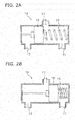
- FIG. 2 is a cross-sectional view of a structure of the switch valve 14.
- the switch valve 14 is a thermostat that is switched in accordance with the temperature of the lubricating oil to be supplied to the cylinder head 2, and includes a thermo-element 15 and an urging member 16.
- the thermo-element 15 is held in a position shown in diagram (A) of FIG. 2 by the urging force of the urging member 16.
- the switch valve 14 connects the first suction port 11 and a connecting port 17 leading to the oil pump 13. Accordingly, the lubricating oil is sucked from the first oil compartment 5a through the first suction port 11 by the oil pump 13, and is supplied to the cylinder head 2 through the supply pathway 8.
- thermo-element 15 displaces against the urging force of the urging member 16 and moves to a position shown in diagram (B) of FIG. 2 .
- the switch valve 14 connects the second suction port 12 and the connecting port 17 leading to the oil pump 13. Accordingly, the lubricating oil is sucked from the second oil compartment 5b through the second suction port 12 by the oil pump 13, and is supplied to the cylinder head 2 through the supply pathway 8.
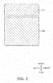
- FIG. 3 is a schematic diagram showing a top view layout of the first and second oil compartments 5a and 5b. As shown in FIG. 3 , the first and second oil compartments 5a and 5b are disposed back and forth (this layout will be hereinafter referred to as "a first exemplary layout"). The capacity of the first oil compartment 5a is smaller than that of the second oil compartment 5b. It should be noted that the capacity of each oil compartment is defined as meaning the volume of the lubricating oil stored in each oil compartment when the engine 1 in an idling state.
- the surface area of the outer surface of the first oil compartment 5a is smaller than that of the second oil compartment 5b.
- the surface area of the inner surface of the first oil compartment 5a is smaller than that of the second oil compartment 5b. Therefore, the sum of the surface areas of the inner and outer surfaces of the first oil compartment 5a is smaller than that of the second oil compartment 5b.
- the surface area of each oil compartment is defined as meaning the surface area of a spatial region in which the lubricating oil is stored when the engine 1 is in the idling state.
- the first and second oil compartments 5a and 5b are disposed such that the outer surface of the first oil compartment 5a and that of the second oil compartment 5b are exposed outside the engine 1. Therefore, increase in up-and-down directional dimension of the engine 1 can be herein inhibited compared to a configuration that the first and second oil compartments 5a and 5b are disposed up and down to overlap one another.
- the sum of the surface areas of the inner and outer surfaces of the first oil compartment 5a is smaller than that of the second oil compartment 5b. Therefore, when the lubricating oil to be supplied to the cylinder head 2 has a temperature of less than the predetermined value, the lubricating oil is circulated from the first oil compartment 5a, whereby the amount of heat released from the outer wall surface of the first oil compartment 5a can be reduced low. Accordingly, the lubricating oil can be warmed quickly.
- the amount of discharge from the oil pump 13 is increased when engine rotational velocity becomes greater than or equal to idling rotational velocity. Because of this, the volume of the lubricating oil is reduced more in the first oil compartment 5a. Hence, the lubricating oil is unlikely to be cooled by the outside air. As a result, the lubricating oil can be warmed quickly.
- the lubricating oil when the lubricating oil has a temperature of greater than or equal to the predetermined value, the lubricating oil is circulated from the second oil compartment 5b, whereby the heat release amount can be increased. Accordingly, excessive increase in temperature of the lubricating oil can be inhibited.
- first and second oil compartments 5a and 5b are disposed back and forth as shown in the first exemplary layout of FIG. 3 .
- the layout of the first and second oil compartments 5a and 5b is not limited to the first exemplary layout and may be changed.
- Diagram (A) of FIG. 4 shows a second exemplary layout.
- Diagram (B) of FIG. 4 shows a third exemplary layout.
- the first and second oil compartments 5a and 5b may be disposed right and left.
- the first oil compartment 5a may be disposed on the left side, whereas the second oil compartment 5b may be disposed on the right side.
- the first oil compartment 5a may be disposed on the right side, whereas the second oil compartment 5b may be disposed on the left side.
- Diagram (C) of FIG. 4 show a fourth exemplary layout.
- Diagram (D) of FIG. 4 shows a fifth exemplary layout.
- the second oil compartment 5b may be continuously provided to be disposed behind and lateral to the first oil compartment 5a.
- the second oil compartment 5b may be continuously provided to be disposed behind and on the right of the first oil compartment 5a.
- the second oil compartment 5b may be continuously provided to be disposed behind and on the left of the first oil compartment 5a.
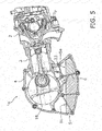
- FIGS. 5 and 6 are cross-sectional views of an engine 1a according to a first practical example.
- the first oil compartment 5a is disposed in front of the second oil compartment 5b.
- the partition 6 extends in the right-and-left direction on the bottom portion of the crankcase 4, and divides the first and second oil compartments 5a and 5b back and forth.
- the first and second oil compartments 5a and 5b are integrated with the crankcase 4.
- the engine 1a includes a cam chain compartment 22 in which a cam chain 21 is disposed.
- the cam chain compartment 22 is provided inside the cylinder head 2, the cylinder 3 and the crankcase 4.
- the lubricating oil supplied to the cylinder head 2 flows therefrom through the cam chain compartment 22 and then returns to the first oil compartment 5a.
- the engine 1a includes an oil guide pathway 23.
- the oil guide pathway 23 leads the lubricating oil from the cylinder 3 and the crankcase 4 to the first oil compartment 5a.
- Part of the partition 6 composes the oil guide pathway 23.
- the partition 6 divides the first and second oil compartments 5a and 5b, and extends to a position between the second oil compartment 5b and a crankshaft 18 disposed inside the crankcase 4. Accordingly, the lubricating oil dripping from the crankshaft 18 flows along the partition 6 and is lead to the first oil compartment 5a.
- the partition 6 is integrated with the crankcase 4. It should be noted that the partition 6 may be provided separately from the crankcase 4.
- FIG. 7 is a cross-sectional view of an engine 1b according to a second practical example.
- the first and second oil compartments 5a and 5b are disposed right and left.
- the partition 6 extends in the back-and-forth direction on the bottom portion of the crankcase 4, and divides the first and second oil compartments 5a and 5b right and left.
- the engine 1b according to the second practical example includes the cam chain compartment 22.
- the first oil compartment 5a is disposed adjacently to the cam chain compartment 22, and the lubricating oil supplied to the cylinder head 2 flows through the cam chain compartment 22 and then returns to the first oil compartment 5a.
- the crankcase 4 has a structure divided right and left. In this case, it is difficult to integrally form the partition 6 and the crankcase 4 by casting. Therefore, it is preferred that the partition 6 is provided separately from the crankcase 4 as a member made of sheet metal or so forth. In this case, it is preferred that the partition 6 is fixed to the crankcase 4 by fastening means such as bolts.
- first and second oil compartments 5a and 5b may be disposed in the fourth exemplary layout described above.
- FIGS. 8 and 9 are cross-sectional views of an engine 1c according to a third practical example.
- the first and second oil compartments 5a and 5b are disposed right and left.
- a cover 24, provided separately from the crankcase 4, is attached to the crankcase 4.
- the engine 1 c according to the third practical example includes an electric power generator 25, and the electric power generator 25 is covered with the cover 24.
- the first oil compartment 5a is disposed adjacently to a space in which the electric power generator 25 is disposed.
- portion of the first oil compartment 5a is integrated with the cover 24.
- the first oil compartment 5a is provided in the crankcase 4 as well as in the cover 24. It should be noted that portion of the second oil compartment 5b may be integrated with the cover 24.
- the first and second oil compartments 5a and 5b may be disposed in the fifth exemplary layout described above.
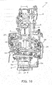
- FIGS. 10 and 11 are cross-sectional views of an engine 1d according to a fourth practical example.
- the engine 1d according to the fourth practical example similarly to the third exemplary layout described above, the first and second oil compartments 5a and 5b are disposed right and left.
- the engine 1d according to the fourth practical example is a single-cylinder engine including a manual transmission 26.
- the manual transmission 26 includes a plurality of shift gears 27 and a clutch 28.
- the clutch 28 is covered with the cover 24.
- reference sign 27 is assigned to only part of the plural shift gears 27.
- the first oil compartment 5a is disposed adjacently to a space in which the clutch 28 is disposed.
- the second oil compartment 5b is disposed adjacently to a space in which the shift gears 27 are disposed.
- the first oil compartment 5a is provided in the cover 24 as well as in the crankcase 4.
- the second oil compartment 5b is integrated with the crankcase 4.
- the oil guide pathway 23 is disposed between the second oil compartment 5b and the space in which the shift gears 27 are disposed.
- the lubricating oil dripping from the shift gears 27 flows along the oil guide pathway 23, and is thus led to the first oil compartment 5a.
- the first and second oil compartments 5a and 5b may be disposed in the fifth exemplary layout described above.
- FIG. 12 is a cross-sectional view of an engine 1e according to a fifth practical example.
- the engine 1e according to the fifth practical example similarly to the third exemplary layout described above, the first and second oil compartments 5a and 5b are disposed right and left.
- the engine 1e according to the fifth practical example is a multicylinder engine including the manual transmission 26.
- an oil pan 29, provided separately from the crankcase 4, is attached to the crankcase 4.
- the first and second oil compartments 5a and 5b are integrated with the oil pan 29.
- the partition 6 is integrated with the oil pan 29. Alternatively, the partition 6 may be provided separately from the oil pan 29.
- the first oil compartment 5a is disposed adjacently to a space in which the clutch 28 is disposed.
- the second oil compartment 5b is disposed adjacently to a space in which the plural shift gears 27 of the manual transmission 26 are disposed.
- the oil guide pathway 23 is disposed between the second oil compartment 5b and the space in which the plural shift gears 27 are disposed, and leads the lubricating oil dripping from the plural shift gears 27 to the first oil compartment 5a.
- the first and second oil compartments 5a and 5b may be disposed in the fifth exemplary layout described above.
- the first and second oil compartments 5a and 5b may be disposed in the first exemplary layout described above.
- FIG. 13 is a side view of a straddled vehicle 100 that is an exemplary straddled vehicle in which the engine 1 is installed.
- the straddled vehicle 100 is a motorcycle of a scooter type.
- the straddled vehicle 100 includes a steering device 101, a vehicle body 102, a power unit 103, a front wheel 104, a rear wheel 105 and a seat 106.
- the steering device 101 includes a front fork 107.
- the front fork 107 supports the front wheel 104 such that the front wheel 104 is rotatable.
- a handle 108 is provided on the upper portion of the steering device 101.
- the vehicle body 102 includes a front cover 131, a rear cover 133 and a lower cover 134.
- the front cover 131 covers the steering device 101 from the front and the back.
- the rear cover 133 is disposed below the seat 106.
- the lower cover 134 is disposed between the front cover 131 and the rear cover 133.
- the upper surface of the lower cover 134 includes a footboard 135.
- the footboard 135 is disposed such that the legs of a rider are put thereon.
- the footboard 135 has a flat shape.
- the footboard 135 may be entirely flat in a vehicle width direction. Alternatively, the footboard 135 may have an upwardly protruding shape in the vehicle width directional middle portion thereof.
- the power unit 103 is disposed below the seat 106.
- the power unit 103 is pivotably supported by the vehicle body 102.
- the power unit 103 supports the rear wheel 105 such that the rear wheel 105 is rotatable.
- the power unit 103 includes the engine 1.
- the engine 1 is disposed below the seat 106.
- the cylinder axis Ax1 of the engine 1 tilts forward and upward.
- FIG. 14 is a side view of a straddled vehicle 200 that is another exemplary straddled vehicle in which the engine 1 according to the aforementioned preferred embodiment is installed.
- the straddled vehicle 200 is a motorcycle of a so-called sport type.
- the straddled vehicle 200 includes a fuel tank 201, a seat 202 and a vehicle body frame 203.
- the fuel tank 201, the seat 202 and the engine 1 are supported by the vehicle body frame 203.
- the fuel tank 201 is disposed in front of the seat 202.
- the engine 1 is disposed below the fuel tank 2.
- the straddled vehicle 200 includes a steering device 204, a front wheel 205, a handle 206 and a headlight unit 207.
- the steering device 204 includes a front fork 209.
- the front fork 209 supports the front wheel 205 such that the front wheel 205 is rotatable.
- the handle 206 is provided on the upper portion of the steering device 204.
- the headlight unit 207 is disposed in front of the fuel tank 201.
- the straddled vehicle 200 includes a swing arm 211 and a rear wheel 212.
- the swing arm 211 backwardly extends from the vehicle body frame 203.
- the swing arm 211 is connected to the vehicle body frame 203 while being pivotable up and down.
- the rear wheel 212 is rotatably supported by the rear portion of the swing arm 211.
- the switch valve 14 is not limited to the thermostat, and alternatively, may be an electrically actuated valve or a hydraulically actuated valve.
- the oil guide pathway 23 may lead the lubricating oil to the first oil compartment 5a only when the lubricating oil flows thereto from the cylinder 3. Alternatively, the oil guide pathway 23 may lead the lubricating oil to the first oil compartment 5a only when the lubricating oil flows thereto from the crankcase 4.
- FIG. 15 is a schematic diagram of the engine 1 according to a first modification.
- the engine 1 according to the first modification includes the switch valve 14 provided in the partition 6.
- the switch valve 14 allows or blocks communication between the first oil compartment 5a and the second oil compartment 5b.
- the switch valve 14 is a thermostat that is closed when the lubricating oil has a temperature of less than a predetermined value and is opened when the lubricating oil has a temperature of greater than or equal to the predetermined value.
- a suction port 31 of the supply pathway 8 for supplying the lubricating oil from the oil tank 5 to the cylinder head 2 is opened inside the first oil compartment 5a.
- the switch valve 14 blocks communication between the first oil compartment 5a and the second oil compartment 5b. Accordingly, the oil pump 13 supplies the lubricating oil to the cylinder head 2 from the first oil compartment 5a. The lubricating oil is thus circulated from the first oil compartment 5a, whereby the lubricating oil can be warmed quickly.
- the switch valve 14 allows communication between the first oil compartment 5a and the second oil compartment 5b. Accordingly, the oil pump 13 supplies the lubricating oil to the cylinder head 2 from both the first oil compartment 5a and the second oil compartment 5b. The lubricating oil is thus circulated from both the first oil compartment 5a and the second oil compartment 5b, whereby excessive increase in temperature of the lubricating oil can be inhibited.
- FIG. 16 is a schematic diagram of the engine 1 according to a second modification.
- oil pumps 13a and 13b which are independent from each other, are provided in the first and second oil compartments 5a and 5b, respectively.
- the engine 1 according to the second modification includes a first oil pump 13a and a second oil pump 13b.
- the first oil pump 13a sucks the lubricating oil from the first oil compartment 5a through the first suction port 11.
- the second oil pump 13b sucks the lubricating oil from the second oil compartment 5b through the second suction port 12.
- the first oil pump 13a When the lubricating oil to be supplied to the cylinder head 2 has a temperature of less than a predetermined value, the first oil pump 13a is driven. Accordingly, the lubricating oil is supplied to the cylinder head 2 from the first oil compartment 5a. When the lubricating oil to be supplied to the cylinder head 2 has a temperature of greater than or equal to the predetermined value, the first and second oil pumps 13a and 13b are driven. Accordingly, the lubricating oil is supplied to the cylinder head 2 from the first oil compartment 5a and the second oil compartment 5b.
- FIG. 17 is a schematic diagram of the engine 1 according to a third modification.
- the first oil compartment 5a is disposed behind the second oil compartment 5b. Additionally, an oil guide pathway 32 is disposed above the second oil compartment 5b. The oil guide pathway 32 leads the lubricating oil from the cylinder head 2, the cylinder 3 or the crankcase 4 to the first oil compartment 5a.
- the surface area of the second oil compartment 5b may be expanded by providing the second oil compartment 5b with fins.
- FIG. 18 is a schematic diagram of the engine 1 according to a fourth modification. As shown in FIG. 18 , the second oil compartment 5b is provided with a plurality of fins 33 protruding from the inner surface of the second oil compartment 5b. The surface area of the inner surface of the second oil compartment 5b is expanded by providing the second oil compartment 5b with the fins 33. Accordingly, the amount of heat released in the second oil compartment 5b can be increased.
- the fins 33 may protrude from the outer surface of the second oil compartment 5b. Accordingly, the surface area of the outer surface of the second oil compartment 5b can be expanded. Alternatively, the fins 33 may be provided to protrude from both the outer surface and the inner surface of the second oil compartment 5b.
- the structure of the switch valve 14 may be changed.
- the switch valve 14 may be switched to a state in which the thermo-element 15 is set in an intermediate position so as to suck the lubricating oil from both the first oil compartment 5a and the second oil compartment 5b.
- the switch valve 14 connects the first suction port 11 and the connecting port 17, and simultaneously, connects the second suction port 12 and the connecting port 17. Accordingly, the lubricating oil is sucked from the first oil compartment 5a and the second oil compartment 5b by the oil pump 13, and is supplied to the cylinder head 2 through the supply pathway 8.
- crankcase and the oil tank are configured as one unit.
- crankcase and the oil tank are configured separately.
Landscapes
- Engineering & Computer Science (AREA)
- Mechanical Engineering (AREA)
- General Engineering & Computer Science (AREA)
- Lubrication Of Internal Combustion Engines (AREA)
- Lubrication Details And Ventilation Of Internal Combustion Engines (AREA)
Abstract
compartment (5A,5B) are exposed outside an engine (1). A sum of a surface area of an inner surface and a surface area of the outer surface of the first oil compartment (5Am5B) is smaller than a sum of a surface area of an inner surface and a surface area of the outer surface of the second oil compartment (5A,5B).
Description
- The present invention relates to an engine and a method for supplying lubricating oil to a cylinder head of an engine.
- It is preferred to warm lubricating oil quickly when the lubricating oil has a low temperature in such a condition as engine starting. Friction loss due to the lubricating oil is quickly reduced by quickly warming the lubricating oil, whereby enhancement in fuel consumption or reduction in exhaust gas can be achieved.
- Because of the above, it has been proposed to use a double sump oil pan in the field of automobiles. For example, an engine described in
JP 2006-77697 A - When the lubricating oil has a temperature of less than or equal to a predetermined value, the thermostat valve is closed. With this configuration, the lubricating oil flows only from the sub compartment and circulates through the interior of the engine. Accordingly, the lubricating oil can be warmed quickly. On the other hand, when the lubricating oil has a temperature of greater than the predetermined value, the thermostat valve is opened. With this configuration, the lubricating oil flows from the main compartment as well as the sub compartment and circulates through the interior of the engine. Accordingly, excessive increase in temperature of the lubricating oil can be inhibited.
- However, when the oil pan has a structure divided up and down as described above, increase in up-and-down directional dimension of the engine is inevitable. It is true of straddled vehicles, but is not the case for automobiles, that the up-and-down directional dimension of the engine affects the vehicle lowest height from the ground. Therefore, increase in up-and-down directional dimension of the engine is not preferred.
- It is an object of the present invention to provide engine and a method for supplying lubricating oil to a cylinder head of an engine which can achieve quick warming of lubricating oil and inhibition of excessive increase in temperature of the lubricating oil with a compact structure. According to the present invention said object is solved by engine having the features of
independent claim 1. Moreover, said object is also solved by method for supplying lubricating oil to a cylinder head of an engine having the features ofindependent claim 15. Preferred embodiments are laid down in the dependent claims. With said teaching applied to an engine in a straddled vehicle, inhibition of increase in up-and-down directional dimension of the engine, and besides, quick warming of lubricating oil and inhibition of excessive increase in temperature of the lubricating oil can be achieved. - An engine according to an aspect includes a cylinder head, a cylinder, a crankcase and an oil tank. The cylinder is connected to the cylinder head. The crankcase is connected to the cylinder. The oil tank includes a first oil compartment and a second oil compartment, and is disposed below the crankcase.
- The cylinder head is supplied with a lubricating oil from the first oil compartment when the lubricating oil has a temperature of less than a predetermined value. The cylinder head is supplied with the lubricating oil at least from the second oil compartment when the lubricating oil has a temperature of greater than or equal to the predetermined value.
- An outer surface of the first oil compartment is exposed outside the engine. An outer surface of the second oil compartment is exposed outside the engine. A sum of a surface area of an inner surface and a surface area of the outer surface of the first oil compartment is less than a sum of a surface area of an inner surface and a surface area of the outer surface of the second oil compartment.
- In the engine according to the present aspect, the first oil compartment and the second oil compartment are disposed such that the outer surface of the first oil compartment and that of the second oil compartment are exposed outside the engine. Therefore, increase in up-and-down directional dimension of the engine can be inhibited compared to a configuration that the first and second compartments are disposed up and down to overlap one another.
- Additionally, the sum of the surface areas of the inner and outer surfaces of the first oil compartment is smaller than that of the second oil compartment. Therefore, when the lubricating oil has a low temperature, the lubricating oil is circulated from the first oil compartment, whereby the amount of heat released from the outer surface of the first oil compartment can be reduced low. Accordingly, the lubricating oil can be warmed quickly. On the other hand, when the lubricating oil has a high temperature, the lubricating oil is circulated from the second oil compartment, whereby the heat release amount can be increased. Accordingly, excessive increase in temperature of the lubricating oil can be inhibited.
- The lubricating oil from the cylinder head may return to the first oil compartment.
- The cylinder head, the cylinder and the crankcase may be provided with a cam chain compartment inside thereof. The first oil compartment may be disposed adjacently to the cam chain compartment. The lubricating oil from the cylinder head may return to the first oil compartment through the cam chain compartment.
- The lubricating oil from the cylinder and/or the crankcase may return to the first oil compartment.
- It should be noted that in returning to the first oil compartment, the lubricating oil may return to the first oil compartment via the second oil compartment. Alternatively, the lubricating oil may return to the first oil compartment without via the second oil compartment.
- The engine may further include an oil guide pathway. The oil guide pathway may lead the lubricating oil from the cylinder and/or the crankcase to flow to the first oil compartment.
- The first oil compartment may have a smaller capacity than the second oil compartment.
- The outer surface of the first oil compartment may have a smaller area than the outer surface of the second oil compartment.
- The inner surface of the first oil compartment may have a smaller area than the inner surface of the second oil compartment.
- The second oil compartment may include a fin protruding from the inner surface or the outer surface of the second oil compartment.
- The first oil compartment and the second oil compartment may be provided adjacently to each other. The engine may further include a partition and a switch valve. The partition may be disposed between the first oil compartment and the second oil compartment, and may divide the first oil compartment and the second oil compartment. The switch valve may be provided in the partition, and may allow or block communication between the first oil compartment and the second oil compartment. The switch valve may block the communication between the first oil compartment and the second oil compartment when the lubricating oil supplied to the cylinder head has the temperature of less than the predetermined value. The switch valve may allow the communication between the first oil compartment and the second oil compartment when the lubricating oil supplied to the cylinder head has the temperature of greater than or equal to the predetermined value. A suction port of a supply pathway for supplying the lubricating oil to the cylinder head from the oil tank may be opened inside the first oil compartment.
- The switch may be a thermostat that is closed when the lubricating oil has the temperature of less than the predetermined value and is opened when the lubricating oil has the temperature of greater than or equal to the predetermined value.
- The engine may further include a cover attached to the crankcase. The partition may be integrated with the crankcase or the cover.
- At least portion of the oil tank may be integrated with the crankcase.
- The cylinder may be disposed in front of the crankcase. The cylinder head may be disposed in front of the cylinder. The cylinder may have a cylinder axis extending forward and obliquely upward. The first oil compartment may be disposed in front of the second oil compartment.
-
-
FIG. 1 is a schematic diagram of a configuration of an engine according to a preferred embodiment. -
FIG. 2 is a cross-sectional view of a structure of a switch valve. -
FIG. 3 is a schematic diagram showing a top view layout of a first oil compartment and a second oil compartment. -
FIG. 4 is a schematic diagram showing another exemplary top view layout of the first oil compartment and the second oil compartment. -
FIG. 5 is a cross-sectional view of an engine according to a first practical example. -
FIG. 6 is a cross-sectional view of the engine according to the first practical example. -
FIG. 7 is a cross-sectional view of an engine according to a second practical example. -
FIG. 8 is a cross-sectional view of an engine according to a third practical example. -
FIG. 9 is a cross-sectional view of the engine according to the third practical example. -
FIG. 10 is a cross-sectional view of an engine according to a fourth practical example. -
FIG. 11 is a cross-sectional view of the engine according to the fourth practical example. -
FIG. 12 is a cross-sectional view of an engine according to a fifth practical example. -
FIG. 13 is a side view of an exemplary straddled vehicle in which the engine according to the preferred embodiment is installed. -
FIG. 14 is a side view of another exemplary straddled vehicle in which the engine according to the preferred embodiment is installed. -
FIG. 15 is a schematic diagram of an engine according to a first modification. -
FIG. 16 is a schematic diagram of an engine according to a second modification. -
FIG. 17 is a schematic diagram of an engine according to a third modification. -
FIG. 18 is a schematic diagram of an engine according to a fourth modification. -
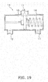
FIG. 19 is a cross-sectional view of a switch valve according to a modification. - A preferred embodiment will be hereinafter explained with reference to drawings.
FIG. 1 is a schematic diagram of a configuration of anengine 1 according to the preferred embodiment. It should be noted that in the following explanation, front, rear, left, right, up and down directions are defined as meaning the front, rear, left, right, up and down directions, respectively, based on a condition that theengine 1 is installed in a straddled vehicle to be described. - As shown in
FIG. 1 , theengine 1 includes acylinder head 2, acylinder 3, acrankcase 4 and anoil tank 5. Thecylinder head 2 is disposed in front of thecylinder 3. A cylinder axis Ax1 of thecylinder 3 extends forward and obliquely upward. Thecylinder 3 is connected to thecylinder head 2. Thecylinder 3 is disposed in front of thecrankcase 4. Thecrankcase 4 is connected to thecylinder 3. - The
oil tank 5 is disposed below thecrankcase 4. Theoil tank 5 stores lubricating oil. Theoil tank 5 includes afirst oil compartment 5a and asecond oil compartment 5b. The outer surface of thefirst oil compartment 5a and that of thesecond oil compartment 5b are exposed outside theengine 1. Each of the first andsecond oil compartments - The first and
second oil compartments partition 6 is disposed between thefirst oil compartment 5a and thesecond oil compartment 5b, whereby the first andsecond oil compartment partition 6. Thepartition 6 includes acommunication hole 7. The first andsecond oil compartments communication hole 7. - The
engine 1 includes asupply pathway 8 for the lubricating oil, and is switchable between a first state and a second state. In the first state of theengine 1, thecylinder head 2 is supplied with the lubricating oil from thefirst oil compartment 5a through thesupply pathway 8. In the second state of theengine 1, thecylinder head 2 is supplied with the lubricating oil from thesecond oil compartment 5b through thesupply pathway 8. The lubricating oil supplied to thecylinder head 2 returns therefrom to thefirst oil compartment 5a through, for instance, a cam chain compartment to be described. Additionally, the lubricating oil supplied to thecylinder 3 and thecrankcase 4 also returns therefrom to thefirst oil compartment 5a. - The
supply pathway 8 includes afirst suction port 11 and asecond suction port 12. Thefirst suction port 11 is opened in thefirst oil compartment 5a. Thesecond suction port 12 is opened in thesecond oil compartment 5b. Theengine 1 includes anoil pump 13 and aswitch valve 14.FIG. 2 is a cross-sectional view of a structure of theswitch valve 14. - The
switch valve 14 is a thermostat that is switched in accordance with the temperature of the lubricating oil to be supplied to thecylinder head 2, and includes a thermo-element 15 and an urgingmember 16. When the lubricating oil to be supplied to thecylinder head 2 has a temperature of less than the predetermined value, the thermo-element 15 is held in a position shown in diagram (A) ofFIG. 2 by the urging force of the urgingmember 16. In this state, theswitch valve 14 connects thefirst suction port 11 and a connectingport 17 leading to theoil pump 13. Accordingly, the lubricating oil is sucked from thefirst oil compartment 5a through thefirst suction port 11 by theoil pump 13, and is supplied to thecylinder head 2 through thesupply pathway 8. - When the lubricating oil has a temperature of greater than or equal to the predetermined value, the thermo-
element 15 displaces against the urging force of the urgingmember 16 and moves to a position shown in diagram (B) ofFIG. 2 . In this state, theswitch valve 14 connects thesecond suction port 12 and the connectingport 17 leading to theoil pump 13. Accordingly, the lubricating oil is sucked from thesecond oil compartment 5b through thesecond suction port 12 by theoil pump 13, and is supplied to thecylinder head 2 through thesupply pathway 8. -
FIG. 3 is a schematic diagram showing a top view layout of the first andsecond oil compartments FIG. 3 , the first andsecond oil compartments first oil compartment 5a is smaller than that of thesecond oil compartment 5b. It should be noted that the capacity of each oil compartment is defined as meaning the volume of the lubricating oil stored in each oil compartment when theengine 1 in an idling state. - The surface area of the outer surface of the
first oil compartment 5a is smaller than that of thesecond oil compartment 5b. The surface area of the inner surface of thefirst oil compartment 5a is smaller than that of thesecond oil compartment 5b. Therefore, the sum of the surface areas of the inner and outer surfaces of thefirst oil compartment 5a is smaller than that of thesecond oil compartment 5b. It should be noted that the surface area of each oil compartment is defined as meaning the surface area of a spatial region in which the lubricating oil is stored when theengine 1 is in the idling state. - In the
engine 1 according to the present preferred embodiment, the first andsecond oil compartments first oil compartment 5a and that of thesecond oil compartment 5b are exposed outside theengine 1. Therefore, increase in up-and-down directional dimension of theengine 1 can be herein inhibited compared to a configuration that the first andsecond oil compartments - Additionally, the sum of the surface areas of the inner and outer surfaces of the
first oil compartment 5a is smaller than that of thesecond oil compartment 5b. Therefore, when the lubricating oil to be supplied to thecylinder head 2 has a temperature of less than the predetermined value, the lubricating oil is circulated from thefirst oil compartment 5a, whereby the amount of heat released from the outer wall surface of thefirst oil compartment 5a can be reduced low. Accordingly, the lubricating oil can be warmed quickly. - Especially in traveling of the vehicle, the amount of discharge from the
oil pump 13 is increased when engine rotational velocity becomes greater than or equal to idling rotational velocity. Because of this, the volume of the lubricating oil is reduced more in thefirst oil compartment 5a. Hence, the lubricating oil is unlikely to be cooled by the outside air. As a result, the lubricating oil can be warmed quickly. - On the other hand, when the lubricating oil has a temperature of greater than or equal to the predetermined value, the lubricating oil is circulated from the
second oil compartment 5b, whereby the heat release amount can be increased. Accordingly, excessive increase in temperature of the lubricating oil can be inhibited. - In the aforementioned preferred embodiment, the first and
second oil compartments FIG. 3 . However, the layout of the first andsecond oil compartments - Diagram (A) of
FIG. 4 shows a second exemplary layout. Diagram (B) ofFIG. 4 shows a third exemplary layout. As shown in diagrams (A) and (B) ofFIG. 4 , the first andsecond oil compartments FIG. 4 , thefirst oil compartment 5a may be disposed on the left side, whereas thesecond oil compartment 5b may be disposed on the right side. Alternatively, as shown in diagram (B) ofFIG. 4 , thefirst oil compartment 5a may be disposed on the right side, whereas thesecond oil compartment 5b may be disposed on the left side. - Diagram (C) of
FIG. 4 show a fourth exemplary layout. Diagram (D) ofFIG. 4 shows a fifth exemplary layout. As shown in diagrams (C) and (D) ofFIG. 4 , thesecond oil compartment 5b may be continuously provided to be disposed behind and lateral to thefirst oil compartment 5a. As shown in diagram (C) ofFIG. 4 , thesecond oil compartment 5b may be continuously provided to be disposed behind and on the right of thefirst oil compartment 5a. Alternatively, as shown in diagram (D) ofFIG. 4 , thesecond oil compartment 5b may be continuously provided to be disposed behind and on the left of thefirst oil compartment 5a. -
FIGS. 5 and6 are cross-sectional views of anengine 1a according to a first practical example. In theengine 1a according to the first practical example, similarly to the first exemplary layout described above, thefirst oil compartment 5a is disposed in front of thesecond oil compartment 5b. Thepartition 6 extends in the right-and-left direction on the bottom portion of thecrankcase 4, and divides the first andsecond oil compartments second oil compartments crankcase 4. - As shown in
FIG. 6 , theengine 1a according to the first practical example includes acam chain compartment 22 in which acam chain 21 is disposed. Thecam chain compartment 22 is provided inside thecylinder head 2, thecylinder 3 and thecrankcase 4. The lubricating oil supplied to thecylinder head 2 flows therefrom through thecam chain compartment 22 and then returns to thefirst oil compartment 5a. - As shown in
FIG. 5 , theengine 1a according to the first practical example includes anoil guide pathway 23. Theoil guide pathway 23 leads the lubricating oil from thecylinder 3 and thecrankcase 4 to thefirst oil compartment 5a. Part of thepartition 6 composes theoil guide pathway 23. Thepartition 6 divides the first andsecond oil compartments second oil compartment 5b and acrankshaft 18 disposed inside thecrankcase 4. Accordingly, the lubricating oil dripping from thecrankshaft 18 flows along thepartition 6 and is lead to thefirst oil compartment 5a. Thepartition 6 is integrated with thecrankcase 4. It should be noted that thepartition 6 may be provided separately from thecrankcase 4. -
FIG. 7 is a cross-sectional view of anengine 1b according to a second practical example. In theengine 1 b according to the second practical example, similarly to the second exemplary layout described above, the first andsecond oil compartments partition 6 extends in the back-and-forth direction on the bottom portion of thecrankcase 4, and divides the first andsecond oil compartments - Similarly to the
engine 1a according to the first practical example, theengine 1b according to the second practical example includes thecam chain compartment 22. Thefirst oil compartment 5a is disposed adjacently to thecam chain compartment 22, and the lubricating oil supplied to thecylinder head 2 flows through thecam chain compartment 22 and then returns to thefirst oil compartment 5a. - In the
engine 1 b according to the second practical example, thecrankcase 4 has a structure divided right and left. In this case, it is difficult to integrally form thepartition 6 and thecrankcase 4 by casting. Therefore, it is preferred that thepartition 6 is provided separately from thecrankcase 4 as a member made of sheet metal or so forth. In this case, it is preferred that thepartition 6 is fixed to thecrankcase 4 by fastening means such as bolts. - It should be noted that in the
engine 1 b according to the second practical example, the first andsecond oil compartments -
FIGS. 8 and9 are cross-sectional views of anengine 1c according to a third practical example. In theengine 1c according to the third practical example, similarly to the third exemplary layout described above, the first andsecond oil compartments engine 1c according to the third practical example, acover 24, provided separately from thecrankcase 4, is attached to thecrankcase 4. Theengine 1 c according to the third practical example includes anelectric power generator 25, and theelectric power generator 25 is covered with thecover 24. Thefirst oil compartment 5a is disposed adjacently to a space in which theelectric power generator 25 is disposed. - portion of the
first oil compartment 5a is integrated with thecover 24. Thefirst oil compartment 5a is provided in thecrankcase 4 as well as in thecover 24. It should be noted that portion of thesecond oil compartment 5b may be integrated with thecover 24. - It should be noted that in the
engine 1c according to the third practical example, the first andsecond oil compartments -
FIGS. 10 and11 are cross-sectional views of anengine 1d according to a fourth practical example. In theengine 1d according to the fourth practical example, similarly to the third exemplary layout described above, the first andsecond oil compartments engine 1d according to the fourth practical example is a single-cylinder engine including amanual transmission 26. As shown inFIG. 10 , themanual transmission 26 includes a plurality of shift gears 27 and a clutch 28. The clutch 28 is covered with thecover 24. It should be noted that in the drawings,reference sign 27 is assigned to only part of the plural shift gears 27. - In the
engine 1d according to the fourth practical example, thefirst oil compartment 5a is disposed adjacently to a space in which the clutch 28 is disposed. Thesecond oil compartment 5b is disposed adjacently to a space in which the shift gears 27 are disposed. Thefirst oil compartment 5a is provided in thecover 24 as well as in thecrankcase 4. Thesecond oil compartment 5b is integrated with thecrankcase 4. - The
oil guide pathway 23 is disposed between thesecond oil compartment 5b and the space in which the shift gears 27 are disposed. The lubricating oil dripping from the shift gears 27 flows along theoil guide pathway 23, and is thus led to thefirst oil compartment 5a. - It should be noted that in the
engine 1d according to the fourth practical example, the first andsecond oil compartments -
FIG. 12 is a cross-sectional view of anengine 1e according to a fifth practical example. In theengine 1e according to the fifth practical example, similarly to the third exemplary layout described above, the first andsecond oil compartments engine 1e according to the fifth practical example is a multicylinder engine including themanual transmission 26. - In the
engine 1e according to the fifth practical example, anoil pan 29, provided separately from thecrankcase 4, is attached to thecrankcase 4. The first andsecond oil compartments oil pan 29. Thepartition 6 is integrated with theoil pan 29. Alternatively, thepartition 6 may be provided separately from theoil pan 29. - In the
engine 1 e according to the fifth practical example, similarly to theengine 1d according to the fourth practical example, thefirst oil compartment 5a is disposed adjacently to a space in which the clutch 28 is disposed. Thesecond oil compartment 5b is disposed adjacently to a space in which the plural shift gears 27 of themanual transmission 26 are disposed. Additionally, theoil guide pathway 23 is disposed between thesecond oil compartment 5b and the space in which the plural shift gears 27 are disposed, and leads the lubricating oil dripping from the plural shift gears 27 to thefirst oil compartment 5a. - It should be noted that in the
engine 1 e according to the fifth practical example, the first andsecond oil compartments engine 1e according to the fifth practical example, the first andsecond oil compartments - Next, a straddled vehicle, in which the
engine 1 according to the aforementioned preferred embodiment is installed, will be explained.FIG. 13 is a side view of a straddledvehicle 100 that is an exemplary straddled vehicle in which theengine 1 is installed. The straddledvehicle 100 is a motorcycle of a scooter type. The straddledvehicle 100 includes asteering device 101, avehicle body 102, apower unit 103, afront wheel 104, arear wheel 105 and aseat 106. - The
steering device 101 includes afront fork 107. Thefront fork 107 supports thefront wheel 104 such that thefront wheel 104 is rotatable. Ahandle 108 is provided on the upper portion of thesteering device 101. - The
vehicle body 102 includes afront cover 131, arear cover 133 and alower cover 134. Thefront cover 131 covers thesteering device 101 from the front and the back. Therear cover 133 is disposed below theseat 106. Thelower cover 134 is disposed between thefront cover 131 and therear cover 133. The upper surface of thelower cover 134 includes afootboard 135. Thefootboard 135 is disposed such that the legs of a rider are put thereon. Thefootboard 135 has a flat shape. Thefootboard 135 may be entirely flat in a vehicle width direction. Alternatively, thefootboard 135 may have an upwardly protruding shape in the vehicle width directional middle portion thereof. - The
power unit 103 is disposed below theseat 106. Thepower unit 103 is pivotably supported by thevehicle body 102. Thepower unit 103 supports therear wheel 105 such that therear wheel 105 is rotatable. Thepower unit 103 includes theengine 1. Theengine 1 is disposed below theseat 106. The cylinder axis Ax1 of theengine 1 tilts forward and upward. -
FIG. 14 is a side view of a straddledvehicle 200 that is another exemplary straddled vehicle in which theengine 1 according to the aforementioned preferred embodiment is installed. The straddledvehicle 200 is a motorcycle of a so-called sport type. The straddledvehicle 200 includes afuel tank 201, aseat 202 and avehicle body frame 203. - The
fuel tank 201, theseat 202 and theengine 1 are supported by thevehicle body frame 203. Thefuel tank 201 is disposed in front of theseat 202. Theengine 1 is disposed below thefuel tank 2. - The straddled
vehicle 200 includes asteering device 204, afront wheel 205, ahandle 206 and aheadlight unit 207. Thesteering device 204 includes afront fork 209. Thefront fork 209 supports thefront wheel 205 such that thefront wheel 205 is rotatable. Thehandle 206 is provided on the upper portion of thesteering device 204. Theheadlight unit 207 is disposed in front of thefuel tank 201. - The straddled
vehicle 200 includes aswing arm 211 and arear wheel 212. Theswing arm 211 backwardly extends from thevehicle body frame 203. Theswing arm 211 is connected to thevehicle body frame 203 while being pivotable up and down. Therear wheel 212 is rotatably supported by the rear portion of theswing arm 211. - One preferred embodiment has been explained above. However, the present teaching is not limited to the aforementioned preferred embodiment, and a variety of changes can be made without departing from the gist of the present teaching.
- The
switch valve 14 is not limited to the thermostat, and alternatively, may be an electrically actuated valve or a hydraulically actuated valve. Theoil guide pathway 23 may lead the lubricating oil to thefirst oil compartment 5a only when the lubricating oil flows thereto from thecylinder 3. Alternatively, theoil guide pathway 23 may lead the lubricating oil to thefirst oil compartment 5a only when the lubricating oil flows thereto from thecrankcase 4. - In the aforementioned preferred embodiment, when the lubricating oil to be supplied to the
cylinder head 2 has a temperature of greater than or equal to the predetermined value, the lubricating oil is supplied from thesecond oil compartment 5b. However, when the lubricating oil to be supplied to thecylinder head 2 has a temperature of greater than or equal to the predetermined value, the lubricating oil may be supplied from both thefirst oil compartment 5a and thesecond oil compartment 5b.FIG. 15 is a schematic diagram of theengine 1 according to a first modification. - As shown in
FIG. 15 , theengine 1 according to the first modification includes theswitch valve 14 provided in thepartition 6. Theswitch valve 14 allows or blocks communication between thefirst oil compartment 5a and thesecond oil compartment 5b. Theswitch valve 14 is a thermostat that is closed when the lubricating oil has a temperature of less than a predetermined value and is opened when the lubricating oil has a temperature of greater than or equal to the predetermined value. - A
suction port 31 of thesupply pathway 8 for supplying the lubricating oil from theoil tank 5 to thecylinder head 2 is opened inside thefirst oil compartment 5a. When the lubricating oil to be supplied to thecylinder head 2 has a temperature of less than the predetermined value, theswitch valve 14 blocks communication between thefirst oil compartment 5a and thesecond oil compartment 5b. Accordingly, theoil pump 13 supplies the lubricating oil to thecylinder head 2 from thefirst oil compartment 5a. The lubricating oil is thus circulated from thefirst oil compartment 5a, whereby the lubricating oil can be warmed quickly. - When the lubricating oil to be supplied to the
cylinder head 2 has a temperature of greater than or equal to the predetermined value, theswitch valve 14 allows communication between thefirst oil compartment 5a and thesecond oil compartment 5b. Accordingly, theoil pump 13 supplies the lubricating oil to thecylinder head 2 from both thefirst oil compartment 5a and thesecond oil compartment 5b. The lubricating oil is thus circulated from both thefirst oil compartment 5a and thesecond oil compartment 5b, whereby excessive increase in temperature of the lubricating oil can be inhibited. - In the aforementioned preferred embodiment, supplying the lubricating oil in the
engine 1 is switched by theswitch valve 14, but may be switched by means other than theswitch valve 14. For example,FIG. 16 is a schematic diagram of theengine 1 according to a second modification. - In the
engine 1 according to the second modification, oil pumps 13a and 13b, which are independent from each other, are provided in the first andsecond oil compartments engine 1 according to the second modification includes afirst oil pump 13a and asecond oil pump 13b. Thefirst oil pump 13a sucks the lubricating oil from thefirst oil compartment 5a through thefirst suction port 11. Thesecond oil pump 13b sucks the lubricating oil from thesecond oil compartment 5b through thesecond suction port 12. - When the lubricating oil to be supplied to the
cylinder head 2 has a temperature of less than a predetermined value, thefirst oil pump 13a is driven. Accordingly, the lubricating oil is supplied to thecylinder head 2 from thefirst oil compartment 5a. When the lubricating oil to be supplied to thecylinder head 2 has a temperature of greater than or equal to the predetermined value, the first and second oil pumps 13a and 13b are driven. Accordingly, the lubricating oil is supplied to thecylinder head 2 from thefirst oil compartment 5a and thesecond oil compartment 5b. - It should be noted that when the lubricating oil to be supplied to the
cylinder head 2 has a temperature of greater than or equal to the predetermined value, only thesecond oil pump 13b may be driven without driving of thefirst oil pump 13a. - In the aforementioned preferred embodiment, the
first oil compartment 5a is disposed in front of thesecond oil compartment 5b. However, thefirst oil compartment 5a may be disposed behind thesecond oil compartment 5b. For example,FIG. 17 is a schematic diagram of theengine 1 according to a third modification. - As shown in
FIG. 17 , in theengine 1 according to the third modification, thefirst oil compartment 5a is disposed behind thesecond oil compartment 5b. Additionally, anoil guide pathway 32 is disposed above thesecond oil compartment 5b. Theoil guide pathway 32 leads the lubricating oil from thecylinder head 2, thecylinder 3 or thecrankcase 4 to thefirst oil compartment 5a. - The surface area of the
second oil compartment 5b may be expanded by providing thesecond oil compartment 5b with fins. For example,FIG. 18 is a schematic diagram of theengine 1 according to a fourth modification. As shown inFIG. 18 , thesecond oil compartment 5b is provided with a plurality offins 33 protruding from the inner surface of thesecond oil compartment 5b. The surface area of the inner surface of thesecond oil compartment 5b is expanded by providing thesecond oil compartment 5b with thefins 33. Accordingly, the amount of heat released in thesecond oil compartment 5b can be increased. - It should be noted that the
fins 33 may protrude from the outer surface of thesecond oil compartment 5b. Accordingly, the surface area of the outer surface of thesecond oil compartment 5b can be expanded. Alternatively, thefins 33 may be provided to protrude from both the outer surface and the inner surface of thesecond oil compartment 5b. - The structure of the
switch valve 14 may be changed. For example, theswitch valve 14 may be switched to a state in which the thermo-element 15 is set in an intermediate position so as to suck the lubricating oil from both thefirst oil compartment 5a and thesecond oil compartment 5b. Specifically, when the thermo-element 15 is set in the intermediate position shown inFIG. 19 , theswitch valve 14 connects thefirst suction port 11 and the connectingport 17, and simultaneously, connects thesecond suction port 12 and the connectingport 17. Accordingly, the lubricating oil is sucked from thefirst oil compartment 5a and thesecond oil compartment 5b by theoil pump 13, and is supplied to thecylinder head 2 through thesupply pathway 8. - In the aforementioned preferred embodiments, the crankcase and the oil tank are configured as one unit. However, within an alternative embodiment, crankcase and the oil tank are configured separately.
Claims (15)
- An engine (1) comprising:a cylinder head (2);a cylinder (3) connected to the cylinder head (2);a crankcase (4) connected to the cylinder (3); andan oil tank (5) including a first oil compartment (5a) and a second oil compartment (5b), the oil tank (5) being disposed below the crankcase (4), whereinthe engine comprises means (14) configured to supply the cylinder head (2) with a lubricating oil from the first oil compartment (5a) when the lubricating oil has a temperature of less than a predetermined value,the engine comprises means (14) configured to supply the cylinder head (2) with the lubricating oil at least from the second oil compartment (5b) when the lubricating oil has a temperature of greater than or equal to the predetermined value,an outer surface of the first oil compartment (5a) is exposed outside the engine (1), an outer surface of the second oil compartment (5b) is exposed outside the engine (1), anda sum of a surface area of an inner surface and a surface area of the outer surface of the first oil compartment (5a) is less than a sum of a surface area of an inner surface and a surface area of the outer surface of the second oil compartment (5b).
- An engine (1) according to claim 1, wherein the engine comprises means configured to return the lubricating oil from the cylinder head (2) to the first oil compartment (5a).
- An engine (1) according to claim 1 or 2, wherein the cylinder head (2), the cylinder (3) and the crankcase (4) are provided with a cam chain compartment (22) inside thereof, the first oil compartment (5a) is disposed adjacently to the cam chain compartment (22), and the engine comprises means configured to return the lubricating oil from the cylinder head (2) returns to the first oil compartment (5a) through the cam chain compartment (22).
- An engine (1) according to any of claims 1 to 3, wherein the engine comprises means (14) configured to return the lubricating oil from the cylinder (3) and/or the crankcase (4) to the first oil compartment (5a).
- An engine (1) according to any of claims 1 to 4, further comprising an oil guide pathway (23) configured to lead the lubricating oil from the cylinder (3) and/or the crankcase (4) to flow to the first oil compartment (5a).
- An engine (1) according to any of claims 1 to 5, wherein the first oil compartment (5a) has a smaller capacity than the second oil compartment (5b).
- An engine (1) according to any of claims 1 to 6, wherein the outer surface of the first oil compartment (5a) has a smaller area than the outer surface of the second oil compartment (5b).
- An engine (1) according to any of claims 1 to 7, wherein the inner surface of the first oil compartment (5a) has a smaller area than the inner surface of the second oil compartment (5b).
- An engine (1) according to any of claims 1 to 8, wherein the second oil compartment (5b) includes at least one fin (33) protruding from the inner surface or the outer surface of the second oil compartment (5b).
- An engine (1) according to any of claims 1 to 9, wherein the first oil compartment (5a) and the second oil compartment (5b) are provided adjacently to each other,
the engine (1) further comprises
a partition (6) disposed between the first oil compartment (5a) and the second oil compartment (5b), the partition (6) dividing the first oil compartment (5a) and the second oil compartment (5b), and
a switch valve (14) provided in the partition (6), the switch valve (14) is configured to allow or block communication between the first oil compartment (5a) and the second oil compartment (5b),
the switch valve (14) is configured to block the communication between the first oil compartment (5a) and the second oil compartment (5b) when the lubricating oil supplied to the cylinder head (2) has the temperature of less than the predetermined value,
the switch valve (14) is configured to allow the communication between the first oil compartment (5a) and the second oil compartment (5b) when the lubricating oil supplied to the cylinder head (2) has the temperature of greater than or equal to the predetermined value, and
a suction port (11) of a supply pathway (8) for supplying the lubricating oil to the cylinder head (2) from the oil tank (5) is opened inside the first oil compartment (5a). - An engine (1) according to claim 10, wherein the switch valve (14) is a thermostat, the thermostat is configured to be closed when the lubricating oil has the temperature of less than the predetermined value, the thermostat is configured to be opened when the lubricating oil has the temperature of greater than or equal to the predetermined value.
- An engine (1) according to claim 10 or 11, further comprising a cover (24) attached to the crankcase (4), wherein the partition (6) is integrated with the crankcase (4) or the cover (24).
- An engine (1) according to any of claims 1 to 11, wherein at least portion of the oil tank (5) is integrated with the crankcase (4).
- A vehicle provided with an engine (1) according to any of claims 1 to 13, wherein the cylinder (3) is disposed in front of the crankcase (4),
the cylinder head (2) is disposed in front of the cylinder (3),
the cylinder (3) has a cylinder (3) axis extending forward and obliquely upward, and
the first oil compartment (5a) is disposed in front of the second oil compartment (5b). - A method for supplying lubricating oil to a cylinder head (2) of an engine (1) with a cylinder (3) connected to the cylinder head (2), a crankcase (4) connected to the cylinder (3), and an oil tank (5) including a first oil compartment (5a) and a second oil compartment (5b), preferably the oil tank (5) being disposed below the crankcase (4), an outer surface of the first oil compartment (5a) is exposed outside the engine (1), and an outer surface of the second oil compartment (5b) is exposed outside the engine (1), and a sum of a surface area of an inner surface and a surface area of the outer surface of the first oil compartment (5a) is less than a sum of a surface area of an inner surface and a surface area of the outer surface of the second oil compartment (5b), according to the method the cylinder head (2) is supplied with a lubricating oil from the first oil compartment (5a) when the lubricating oil has a temperature of less than a predetermined value, and the cylinder head (2) is supplied with the lubricating oil at least from the second oil compartment (5b) when the lubricating oil has a temperature of greater than or equal to the predetermined value.
Applications Claiming Priority (1)
| Application Number | Priority Date | Filing Date | Title |
|---|---|---|---|
| JP2016204497A JP2018066294A (en) | 2016-10-18 | 2016-10-18 | engine |
Publications (2)
| Publication Number | Publication Date |
|---|---|
| EP3315738A1 true EP3315738A1 (en) | 2018-05-02 |
| EP3315738B1 EP3315738B1 (en) | 2020-05-06 |
Family
ID=60083841
Family Applications (1)
| Application Number | Title | Priority Date | Filing Date |
|---|---|---|---|
| EP17196287.1A Active EP3315738B1 (en) | 2016-10-18 | 2017-10-13 | Engine |
Country Status (2)
| Country | Link |
|---|---|
| EP (1) | EP3315738B1 (en) |
| JP (1) | JP2018066294A (en) |
Families Citing this family (1)
| Publication number | Priority date | Publication date | Assignee | Title |
|---|---|---|---|---|
| JP6843172B2 (en) * | 2019-03-29 | 2021-03-17 | 本田技研工業株式会社 | Internal combustion engine |
Citations (4)
| Publication number | Priority date | Publication date | Assignee | Title |
|---|---|---|---|---|
| JPS57191812U (en) * | 1981-05-31 | 1982-12-04 | ||
| JPS5881306U (en) * | 1981-11-30 | 1983-06-02 | いすゞ自動車株式会社 | Internal combustion engine lubrication system |
| JP2006063925A (en) * | 2004-08-27 | 2006-03-09 | Aichi Mach Ind Co Ltd | Oil passage structure of internal combustion engine |
| JP2006077697A (en) | 2004-09-10 | 2006-03-23 | Toyota Motor Corp | Two tank oil pan |
-
2016
- 2016-10-18 JP JP2016204497A patent/JP2018066294A/en active Pending
-
2017
- 2017-10-13 EP EP17196287.1A patent/EP3315738B1/en active Active
Patent Citations (4)
| Publication number | Priority date | Publication date | Assignee | Title |
|---|---|---|---|---|
| JPS57191812U (en) * | 1981-05-31 | 1982-12-04 | ||
| JPS5881306U (en) * | 1981-11-30 | 1983-06-02 | いすゞ自動車株式会社 | Internal combustion engine lubrication system |
| JP2006063925A (en) * | 2004-08-27 | 2006-03-09 | Aichi Mach Ind Co Ltd | Oil passage structure of internal combustion engine |
| JP2006077697A (en) | 2004-09-10 | 2006-03-23 | Toyota Motor Corp | Two tank oil pan |
Also Published As
| Publication number | Publication date |
|---|---|
| EP3315738B1 (en) | 2020-05-06 |
| JP2018066294A (en) | 2018-04-26 |
Similar Documents
| Publication | Publication Date | Title |
|---|---|---|
| JP3971082B2 (en) | Lubricating device for internal combustion engine | |
| EP1990508B1 (en) | Oil feeding system | |
| EP1258424B1 (en) | Vehicle, especially snowmobile, with an engine and and oil tank | |
| US9863295B2 (en) | Engine unit | |
| US7104242B2 (en) | Internal combustion engine including splash-resistant oil storage structure | |
| EP3315738B1 (en) | Engine | |
| JP2005163570A (en) | Lubricating device for internal combustion engine | |
| US7314115B2 (en) | Lubricating system for internal combustion engine | |
| JP2010216416A (en) | Oil cooler mounting structure and v-type engine equipped with the same | |
| US9599063B2 (en) | Engine unit for vehicle | |
| EP3321480A1 (en) | Straddled vehicle | |
| JP4519747B2 (en) | Small internal combustion engine | |
| US5588406A (en) | Structure for lubricating cam sliding surface in an internal combustion engine | |
| US8522742B2 (en) | Multi-cylinder internal combustion engine | |
| EP2447140A1 (en) | Straddle-ride type vehicle | |
| EP1775433B1 (en) | Adaptor in combination with a crankcase, oil filter in combination with the crankcase and motorcycle including the oil filter | |
| JP6205974B2 (en) | Engine oil strainer structure | |
| JP6299422B2 (en) | Internal combustion engine crankcase and internal combustion engine | |
| US20160017842A1 (en) | Vehicle | |
| JP2010151086A (en) | Vehicle mounted with engine and the engine | |
| US8522743B2 (en) | Multi-cylinder internal combustion engine | |
| JPH11141400A (en) | Oil storage structure of 4-cycle engine | |
| CN204386696U (en) | The oil cooler of internal combustion engine used in saddle vehicle | |
| JP2006316627A (en) | Engine structure | |
| JP6892475B2 (en) | Internal combustion engine |
Legal Events
| Date | Code | Title | Description |
|---|---|---|---|
| PUAI | Public reference made under article 153(3) epc to a published international application that has entered the european phase |
Free format text: ORIGINAL CODE: 0009012 |
|
| STAA | Information on the status of an ep patent application or granted ep patent |
Free format text: STATUS: REQUEST FOR EXAMINATION WAS MADE |
|
| 17P | Request for examination filed |
Effective date: 20171013 |
|
| AK | Designated contracting states |
Kind code of ref document: A1 Designated state(s): AL AT BE BG CH CY CZ DE DK EE ES FI FR GB GR HR HU IE IS IT LI LT LU LV MC MK MT NL NO PL PT RO RS SE SI SK SM TR |
|
| AX | Request for extension of the european patent |
Extension state: BA ME |
|
| RBV | Designated contracting states (corrected) |
Designated state(s): AL AT BE BG CH CY CZ DE DK EE ES FI FR GB GR HR HU IE IS IT LI LT LU LV MC MK MT NL NO PL PT RO RS SE SI SK SM TR |
|
| STAA | Information on the status of an ep patent application or granted ep patent |
Free format text: STATUS: EXAMINATION IS IN PROGRESS |
|
| 17Q | First examination report despatched |
Effective date: 20180928 |
|
| GRAP | Despatch of communication of intention to grant a patent |
Free format text: ORIGINAL CODE: EPIDOSNIGR1 |
|
| STAA | Information on the status of an ep patent application or granted ep patent |
Free format text: STATUS: GRANT OF PATENT IS INTENDED |
|
| RIC1 | Information provided on ipc code assigned before grant |
Ipc: F01M 11/02 20060101ALN20200103BHEP Ipc: F01M 11/00 20060101AFI20200103BHEP Ipc: F01M 5/02 20060101ALN20200103BHEP |
|
| INTG | Intention to grant announced |
Effective date: 20200203 |
|
| GRAS | Grant fee paid |
Free format text: ORIGINAL CODE: EPIDOSNIGR3 |
|
| GRAA | (expected) grant |
Free format text: ORIGINAL CODE: 0009210 |
|
| STAA | Information on the status of an ep patent application or granted ep patent |
Free format text: STATUS: THE PATENT HAS BEEN GRANTED |
|
| AK | Designated contracting states |
Kind code of ref document: B1 Designated state(s): AL AT BE BG CH CY CZ DE DK EE ES FI FR GB GR HR HU IE IS IT LI LT LU LV MC MK MT NL NO PL PT RO RS SE SI SK SM TR |
|
| REG | Reference to a national code |
Ref country code: GB Ref legal event code: FG4D |
|
| REG | Reference to a national code |
Ref country code: CH Ref legal event code: EP Ref country code: AT Ref legal event code: REF Ref document number: 1267069 Country of ref document: AT Kind code of ref document: T Effective date: 20200515 |
|
| REG | Reference to a national code |
Ref country code: DE Ref legal event code: R096 Ref document number: 602017016104 Country of ref document: DE |
|
| REG | Reference to a national code |
Ref country code: IE Ref legal event code: FG4D |
|
| REG | Reference to a national code |
Ref country code: LT Ref legal event code: MG4D |
|
| REG | Reference to a national code |
Ref country code: NL Ref legal event code: MP Effective date: 20200506 |
|
| PG25 | Lapsed in a contracting state [announced via postgrant information from national office to epo] |
Ref country code: SE Free format text: LAPSE BECAUSE OF FAILURE TO SUBMIT A TRANSLATION OF THE DESCRIPTION OR TO PAY THE FEE WITHIN THE PRESCRIBED TIME-LIMIT Effective date: 20200506 Ref country code: FI Free format text: LAPSE BECAUSE OF FAILURE TO SUBMIT A TRANSLATION OF THE DESCRIPTION OR TO PAY THE FEE WITHIN THE PRESCRIBED TIME-LIMIT Effective date: 20200506 Ref country code: IS Free format text: LAPSE BECAUSE OF FAILURE TO SUBMIT A TRANSLATION OF THE DESCRIPTION OR TO PAY THE FEE WITHIN THE PRESCRIBED TIME-LIMIT Effective date: 20200906 Ref country code: PT Free format text: LAPSE BECAUSE OF FAILURE TO SUBMIT A TRANSLATION OF THE DESCRIPTION OR TO PAY THE FEE WITHIN THE PRESCRIBED TIME-LIMIT Effective date: 20200907 Ref country code: GR Free format text: LAPSE BECAUSE OF FAILURE TO SUBMIT A TRANSLATION OF THE DESCRIPTION OR TO PAY THE FEE WITHIN THE PRESCRIBED TIME-LIMIT Effective date: 20200807 Ref country code: NO Free format text: LAPSE BECAUSE OF FAILURE TO SUBMIT A TRANSLATION OF THE DESCRIPTION OR TO PAY THE FEE WITHIN THE PRESCRIBED TIME-LIMIT Effective date: 20200806 Ref country code: LT Free format text: LAPSE BECAUSE OF FAILURE TO SUBMIT A TRANSLATION OF THE DESCRIPTION OR TO PAY THE FEE WITHIN THE PRESCRIBED TIME-LIMIT Effective date: 20200506 |
|
| PG25 | Lapsed in a contracting state [announced via postgrant information from national office to epo] |
Ref country code: LV Free format text: LAPSE BECAUSE OF FAILURE TO SUBMIT A TRANSLATION OF THE DESCRIPTION OR TO PAY THE FEE WITHIN THE PRESCRIBED TIME-LIMIT Effective date: 20200506 Ref country code: RS Free format text: LAPSE BECAUSE OF FAILURE TO SUBMIT A TRANSLATION OF THE DESCRIPTION OR TO PAY THE FEE WITHIN THE PRESCRIBED TIME-LIMIT Effective date: 20200506 Ref country code: BG Free format text: LAPSE BECAUSE OF FAILURE TO SUBMIT A TRANSLATION OF THE DESCRIPTION OR TO PAY THE FEE WITHIN THE PRESCRIBED TIME-LIMIT Effective date: 20200806 Ref country code: HR Free format text: LAPSE BECAUSE OF FAILURE TO SUBMIT A TRANSLATION OF THE DESCRIPTION OR TO PAY THE FEE WITHIN THE PRESCRIBED TIME-LIMIT Effective date: 20200506 |
|
| REG | Reference to a national code |
Ref country code: AT Ref legal event code: MK05 Ref document number: 1267069 Country of ref document: AT Kind code of ref document: T Effective date: 20200506 |
|
| PG25 | Lapsed in a contracting state [announced via postgrant information from national office to epo] |
Ref country code: NL Free format text: LAPSE BECAUSE OF FAILURE TO SUBMIT A TRANSLATION OF THE DESCRIPTION OR TO PAY THE FEE WITHIN THE PRESCRIBED TIME-LIMIT Effective date: 20200506 Ref country code: AL Free format text: LAPSE BECAUSE OF FAILURE TO SUBMIT A TRANSLATION OF THE DESCRIPTION OR TO PAY THE FEE WITHIN THE PRESCRIBED TIME-LIMIT Effective date: 20200506 |
|
| PG25 | Lapsed in a contracting state [announced via postgrant information from national office to epo] |
Ref country code: CZ Free format text: LAPSE BECAUSE OF FAILURE TO SUBMIT A TRANSLATION OF THE DESCRIPTION OR TO PAY THE FEE WITHIN THE PRESCRIBED TIME-LIMIT Effective date: 20200506 Ref country code: RO Free format text: LAPSE BECAUSE OF FAILURE TO SUBMIT A TRANSLATION OF THE DESCRIPTION OR TO PAY THE FEE WITHIN THE PRESCRIBED TIME-LIMIT Effective date: 20200506 Ref country code: SM Free format text: LAPSE BECAUSE OF FAILURE TO SUBMIT A TRANSLATION OF THE DESCRIPTION OR TO PAY THE FEE WITHIN THE PRESCRIBED TIME-LIMIT Effective date: 20200506 Ref country code: EE Free format text: LAPSE BECAUSE OF FAILURE TO SUBMIT A TRANSLATION OF THE DESCRIPTION OR TO PAY THE FEE WITHIN THE PRESCRIBED TIME-LIMIT Effective date: 20200506 Ref country code: DK Free format text: LAPSE BECAUSE OF FAILURE TO SUBMIT A TRANSLATION OF THE DESCRIPTION OR TO PAY THE FEE WITHIN THE PRESCRIBED TIME-LIMIT Effective date: 20200506 Ref country code: AT Free format text: LAPSE BECAUSE OF FAILURE TO SUBMIT A TRANSLATION OF THE DESCRIPTION OR TO PAY THE FEE WITHIN THE PRESCRIBED TIME-LIMIT Effective date: 20200506 Ref country code: ES Free format text: LAPSE BECAUSE OF FAILURE TO SUBMIT A TRANSLATION OF THE DESCRIPTION OR TO PAY THE FEE WITHIN THE PRESCRIBED TIME-LIMIT Effective date: 20200506 |
|
| REG | Reference to a national code |
Ref country code: DE Ref legal event code: R097 Ref document number: 602017016104 Country of ref document: DE |
|
| PG25 | Lapsed in a contracting state [announced via postgrant information from national office to epo] |
Ref country code: SK Free format text: LAPSE BECAUSE OF FAILURE TO SUBMIT A TRANSLATION OF THE DESCRIPTION OR TO PAY THE FEE WITHIN THE PRESCRIBED TIME-LIMIT Effective date: 20200506 Ref country code: PL Free format text: LAPSE BECAUSE OF FAILURE TO SUBMIT A TRANSLATION OF THE DESCRIPTION OR TO PAY THE FEE WITHIN THE PRESCRIBED TIME-LIMIT Effective date: 20200506 |
|
| PLBE | No opposition filed within time limit |
Free format text: ORIGINAL CODE: 0009261 |
|
| STAA | Information on the status of an ep patent application or granted ep patent |
Free format text: STATUS: NO OPPOSITION FILED WITHIN TIME LIMIT |
|
| 26N | No opposition filed |
Effective date: 20210209 |
|
| PG25 | Lapsed in a contracting state [announced via postgrant information from national office to epo] |
Ref country code: SI Free format text: LAPSE BECAUSE OF FAILURE TO SUBMIT A TRANSLATION OF THE DESCRIPTION OR TO PAY THE FEE WITHIN THE PRESCRIBED TIME-LIMIT Effective date: 20200506 |
|
| REG | Reference to a national code |
Ref country code: CH Ref legal event code: PL |
|
| PG25 | Lapsed in a contracting state [announced via postgrant information from national office to epo] |
Ref country code: MC Free format text: LAPSE BECAUSE OF FAILURE TO SUBMIT A TRANSLATION OF THE DESCRIPTION OR TO PAY THE FEE WITHIN THE PRESCRIBED TIME-LIMIT Effective date: 20200506 Ref country code: LU Free format text: LAPSE BECAUSE OF NON-PAYMENT OF DUE FEES Effective date: 20201013 |
|
| REG | Reference to a national code |
Ref country code: BE Ref legal event code: MM Effective date: 20201031 |
|
| PG25 | Lapsed in a contracting state [announced via postgrant information from national office to epo] |
Ref country code: LI Free format text: LAPSE BECAUSE OF NON-PAYMENT OF DUE FEES Effective date: 20201031 Ref country code: CH Free format text: LAPSE BECAUSE OF NON-PAYMENT OF DUE FEES Effective date: 20201031 Ref country code: BE Free format text: LAPSE BECAUSE OF NON-PAYMENT OF DUE FEES Effective date: 20201031 |
|
| PG25 | Lapsed in a contracting state [announced via postgrant information from national office to epo] |
Ref country code: IE Free format text: LAPSE BECAUSE OF NON-PAYMENT OF DUE FEES Effective date: 20201013 |
|
| PG25 | Lapsed in a contracting state [announced via postgrant information from national office to epo] |
Ref country code: TR Free format text: LAPSE BECAUSE OF FAILURE TO SUBMIT A TRANSLATION OF THE DESCRIPTION OR TO PAY THE FEE WITHIN THE PRESCRIBED TIME-LIMIT Effective date: 20200506 Ref country code: MT Free format text: LAPSE BECAUSE OF FAILURE TO SUBMIT A TRANSLATION OF THE DESCRIPTION OR TO PAY THE FEE WITHIN THE PRESCRIBED TIME-LIMIT Effective date: 20200506 Ref country code: CY Free format text: LAPSE BECAUSE OF FAILURE TO SUBMIT A TRANSLATION OF THE DESCRIPTION OR TO PAY THE FEE WITHIN THE PRESCRIBED TIME-LIMIT Effective date: 20200506 |
|
| GBPC | Gb: european patent ceased through non-payment of renewal fee |
Effective date: 20211013 |
|
| PG25 | Lapsed in a contracting state [announced via postgrant information from national office to epo] |
Ref country code: MK Free format text: LAPSE BECAUSE OF FAILURE TO SUBMIT A TRANSLATION OF THE DESCRIPTION OR TO PAY THE FEE WITHIN THE PRESCRIBED TIME-LIMIT Effective date: 20200506 |
|
| PG25 | Lapsed in a contracting state [announced via postgrant information from national office to epo] |
Ref country code: GB Free format text: LAPSE BECAUSE OF NON-PAYMENT OF DUE FEES Effective date: 20211013 |
|
| P01 | Opt-out of the competence of the unified patent court (upc) registered |
Effective date: 20230527 |
|
| PGFP | Annual fee paid to national office [announced via postgrant information from national office to epo] |
Ref country code: IT Payment date: 20231026 Year of fee payment: 7 Ref country code: FR Payment date: 20231026 Year of fee payment: 7 Ref country code: DE Payment date: 20231020 Year of fee payment: 7 |
|
| REG | Reference to a national code |
Ref country code: DE Ref legal event code: R119 Ref document number: 602017016104 Country of ref document: DE |
|
| PG25 | Lapsed in a contracting state [announced via postgrant information from national office to epo] |
Ref country code: DE Free format text: LAPSE BECAUSE OF NON-PAYMENT OF DUE FEES Effective date: 20250501 |
|
| PG25 | Lapsed in a contracting state [announced via postgrant information from national office to epo] |
Ref country code: FR Free format text: LAPSE BECAUSE OF NON-PAYMENT OF DUE FEES Effective date: 20241031 |
|
| PG25 | Lapsed in a contracting state [announced via postgrant information from national office to epo] |
Ref country code: IT Free format text: LAPSE BECAUSE OF NON-PAYMENT OF DUE FEES Effective date: 20241013 |