EP3315733A1 - Turbinenzwischengehäuse für eine gasturbine - Google Patents
Turbinenzwischengehäuse für eine gasturbine Download PDFInfo
- Publication number
- EP3315733A1 EP3315733A1 EP17197918.0A EP17197918A EP3315733A1 EP 3315733 A1 EP3315733 A1 EP 3315733A1 EP 17197918 A EP17197918 A EP 17197918A EP 3315733 A1 EP3315733 A1 EP 3315733A1
- Authority
- EP
- European Patent Office
- Prior art keywords
- turbine
- connecting element
- annular channel
- radially
- intermediate housing
- Prior art date
- Legal status (The legal status is an assumption and is not a legal conclusion. Google has not performed a legal analysis and makes no representation as to the accuracy of the status listed.)
- Granted
Links
- 230000008878 coupling Effects 0.000 claims description 20
- 238000010168 coupling process Methods 0.000 claims description 20
- 238000005859 coupling reaction Methods 0.000 claims description 20
- 239000000725 suspension Substances 0.000 description 3
- 230000005540 biological transmission Effects 0.000 description 2
- 238000007789 sealing Methods 0.000 description 2
- 230000007704 transition Effects 0.000 description 2
- 125000004122 cyclic group Chemical group 0.000 description 1
- 230000008719 thickening Effects 0.000 description 1
- 238000011144 upstream manufacturing Methods 0.000 description 1
Images

Classifications
-
- F—MECHANICAL ENGINEERING; LIGHTING; HEATING; WEAPONS; BLASTING
- F01—MACHINES OR ENGINES IN GENERAL; ENGINE PLANTS IN GENERAL; STEAM ENGINES
- F01D—NON-POSITIVE DISPLACEMENT MACHINES OR ENGINES, e.g. STEAM TURBINES
- F01D25/00—Component parts, details, or accessories, not provided for in, or of interest apart from, other groups
- F01D25/28—Supporting or mounting arrangements, e.g. for turbine casing
-
- F—MECHANICAL ENGINEERING; LIGHTING; HEATING; WEAPONS; BLASTING
- F01—MACHINES OR ENGINES IN GENERAL; ENGINE PLANTS IN GENERAL; STEAM ENGINES
- F01D—NON-POSITIVE DISPLACEMENT MACHINES OR ENGINES, e.g. STEAM TURBINES
- F01D25/00—Component parts, details, or accessories, not provided for in, or of interest apart from, other groups
- F01D25/16—Arrangement of bearings; Supporting or mounting bearings in casings
- F01D25/162—Bearing supports
-
- F—MECHANICAL ENGINEERING; LIGHTING; HEATING; WEAPONS; BLASTING
- F02—COMBUSTION ENGINES; HOT-GAS OR COMBUSTION-PRODUCT ENGINE PLANTS
- F02C—GAS-TURBINE PLANTS; AIR INTAKES FOR JET-PROPULSION PLANTS; CONTROLLING FUEL SUPPLY IN AIR-BREATHING JET-PROPULSION PLANTS
- F02C7/00—Features, components parts, details or accessories, not provided for in, or of interest apart form groups F02C1/00 - F02C6/00; Air intakes for jet-propulsion plants
- F02C7/20—Mounting or supporting of plant; Accommodating heat expansion or creep
-
- F—MECHANICAL ENGINEERING; LIGHTING; HEATING; WEAPONS; BLASTING
- F05—INDEXING SCHEMES RELATING TO ENGINES OR PUMPS IN VARIOUS SUBCLASSES OF CLASSES F01-F04
- F05D—INDEXING SCHEME FOR ASPECTS RELATING TO NON-POSITIVE-DISPLACEMENT MACHINES OR ENGINES, GAS-TURBINES OR JET-PROPULSION PLANTS
- F05D2250/00—Geometry
- F05D2250/30—Arrangement of components
- F05D2250/31—Arrangement of components according to the direction of their main axis or their axis of rotation
- F05D2250/314—Arrangement of components according to the direction of their main axis or their axis of rotation the axes being inclined in relation to each other
-
- F—MECHANICAL ENGINEERING; LIGHTING; HEATING; WEAPONS; BLASTING
- F05—INDEXING SCHEMES RELATING TO ENGINES OR PUMPS IN VARIOUS SUBCLASSES OF CLASSES F01-F04
- F05D—INDEXING SCHEME FOR ASPECTS RELATING TO NON-POSITIVE-DISPLACEMENT MACHINES OR ENGINES, GAS-TURBINES OR JET-PROPULSION PLANTS
- F05D2250/00—Geometry
- F05D2250/30—Arrangement of components
- F05D2250/38—Arrangement of components angled, e.g. sweep angle
Definitions
- the present invention relates to a turbine intermediate housing for a gas turbine, in particular an aircraft gas turbine, with a hot gas segmented annular channel, a radial outer housing, which is arranged at a distance around the annular channel, a hub member which is arranged radially inwardly at a distance from the annular channel, a plurality of substantially radially extending through the annular channel extending struts which are radially inwardly coupled to the hub member and which are radially outwardly coupled to the outer housing, and at least one inclined to the struts formed connecting member which extends through the annular channel and radially inwardly coupled to a seal carrier member, wherein the seal carrier member is axially supported on the front of the hub member.
- Such a turbine intermediate housing is for example from the US 2013 / 0011242A1 known, wherein the connecting element and the struts are coupled to the outer housing and wherein the connecting element and the struts crossing each other are arranged.
- This arrangement of the connecting element leads to force transmission at a plurality of closely spaced points of the outer housing, which results in the occurrence of stresses in the outer housing. Since the strut and the support element intersect in the region of the annular channel, the lining must be dimensioned large there or very "thick" running. This means a large obstacle or a large obstruction for the gas flow, so that corresponding losses occur, in particular also with regard to the overall efficiency of the turbine.
- the object of the invention is to provide a turbine intermediate housing in which the above disadvantages can be avoided.
- At least one connecting element be coupled radially outwardly with one of the struts.
- a relevant strut By coupling with a relevant strut can on another Force introduction in the area of the outer housing are dispensed with. Accordingly, voltages in the outer housing can be reduced.
- the structure of the outer housing is simplified compared with a known outer housing on which the connecting element is supported.
- the connecting element extends in the radial direction and the axial direction. Relative to the radial direction, the connecting element can be arranged at an angle of about 30 ° to 60 °, preferably about 40 ° to 50 °.
- a radially outer end of the connecting element is covered by the outer housing.
- the radially outer end of the connecting element is located radially inside the outer housing. The connecting element is thus not visible from the outside.
- the respective strut has a receiving portion in which the radially outer end of the connecting element is received and supported.
- the receiving portion may be a kind of hollow thickening of the strut, through which the connecting element is guided.
- At a radially outer region of the receiving portion may have a bearing portion on which the connecting element is supported on the strut.
- the connecting element and the respective strut may be arranged in alignment with each other in the axial direction.
- the connecting element and the respective strut thus form a kind of V-shape in the axial direction. If the connecting element and the respective strut are arranged in the axial direction in alignment with each other, form in the annular channel in the flow direction successively arranged elements that can be easily provided with a common sheath.
- the connecting element may have radially inside at least one coupling portion which is coupled to the seal carrier element.
- the coupling portion may be connected in particular as by means of a screw, in particular also screw-nut connection with the seal carrier element.
- the connecting element has two coupling sections, which are formed inclined to each other, preferably such that the connecting element is formed substantially Y-shaped.
- the two coupling sections can be coupled along the circumferential direction at different coupling points with the seal carrier.
- the connecting element may have at its radially outer end a clamping device, by which a force acting on the connecting element biasing force, in particular tensile force is adjustable.
- a clamping device may be formed for example by a nut which is screwed onto an external thread provided on the connecting element. The mother can rest with their edges on the above-mentioned bearing portion of the receiving portion of the strut.
- the connecting element and the relevant strut can be accommodated in the region of the annular channel in a common casing, which is formed on a relevant annular channel segment.
- a common casing which is formed on a relevant annular channel segment.
- Such an annular channel segment, which has a casing for the strut and the connecting element, is also referred to in the jargon as fairing.
- the invention also relates to a gas turbine, in particular an aircraft gas turbine with a first turbine and at least one further turbine, wherein an above-described turbine intermediate housing is arranged between the first turbine and the further turbine.
- Fig. 1 shows a turbine intermediate housing 1 of a gas turbine with an along the axial direction AR upstream high-pressure turbine 2 (first turbine) and a downstream low-pressure turbine 3 (further turbine).
- the turbine intermediate housing has an outer housing 4, which surrounds a segmented annular channel 6 carrying hot gas.
- MA denotes a machine axis of the gas turbine.
- a hub member 7 Radially inside a hub member 7 is provided.
- the hub element 7 and the outer housing 4 are arranged concentrically to the machine axis MA of the gas turbine.
- the hub member 7 is connected by means of a plurality of struts 5 with the outer housing 4.
- the struts 5 extend through the hot gas leading annular channel 6 therethrough.
- the annular channel 6 is formed in particular by annular channel segments which are connected to the outer housing 4 by means of a front flow channel suspension 9 and a rear flow channel suspension 10.
- a sealing air chamber is formed in the sealing air at a higher pressure compared to the pressure in the annular channel 6 is introduced. This ensures that the structural parts and supply lines of a storage chamber 8 do not come into contact with hot gas.
- Axially behind a guide grid 15 is provided before the transition to the low-pressure turbine 3.
- the guide grid 15 is fixed by means of Leitgitterhaken 17 on the outer housing 4.
- a radially inner Leitgitterdichtung 16 prevents a flow of hot gas around the guide grid 15th
- the hub member 7 is designed as a particular box-shaped ring.
- the box-shaped hub member 7 accordingly has a high torsional rigidity.
- the bearing chamber 8 is attached to a seal carrier for a shaft seal 19.
- a (vane) seal carrier member 20 is disposed on the hub member 7.
- a shaft seal carrier is referred to, which is also connected to the hub member 7.
- the seal carrier 20 has a large extent, in particular in the axial direction AR and in the radial direction RR. This leads to a large area on which in particular the pressure difference between P2 and P3 acts.
- the seal carrier 20 is supported in addition to its attachment to the hub member 7 by means of a connecting element 30.
- the support of the seal carrier 20 is effected by connecting elements 30, which are supported on a respective (relevant) strut 5. It is clear that a plurality of connecting elements 30 are arranged distributed in the circumferential direction in order to effectively support the entire seal carrier 20.
- the connecting element 30 By the connecting element 30, a part of the forces is not passed through the hub 7 to the struts 5, but in a direct way on the struts 5 in the outer housing 4.
- the junction of the struts 5 to the hub 7 relieved and thus their life can be extended .
- the affected components, in particular the seal carrier 20, can be made less massive, in particular lighter.
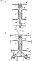
- Fig. 2A shows in a sectional view corresponding to the section line 11-11 of Fig. 1 a first embodiment of the connecting element 30.
- the connecting element 30 is designed as a pull rod.
- the connecting element 30 has, radially on the outside, a threaded section 32 which is connected to a nut 34.
- the nut 34 lies with its radial inner edge on a bearing portion 36 which is formed in a receiving portion 38 of the strut 5.
- biasing force in particular tensile force can be adjusted.
- the screw-nut connection 32, 34 thus forms a kind of tensioning device for the connecting element 30.
- the connecting element has a coupling portion 40.
- the coupling portion 40 also includes a non-visible threaded portion connected to a nut 42.
- the coupling portion 40 is coupled to the seal carrier 20.
- FIG Fig. 2B An alternative embodiment of the connecting element 30 is shown in FIG Fig. 2B ). Radially outward, the connecting element 30 is designed the same, as with respect to the Fig. 2A ) has already been described. Radially inside or at its radially inner end, the connecting element 30 has two coupling sections 40a, 40b. The two coupling portions 40a, 40b are inclined to each other. Accordingly, the coupling of the connecting element 30 takes place on the seal carrier 20 at two spaced apart in the circumferential direction UR points 46a, 46b. In other words, the connecting element 30 is widened fork-shaped or V-shaped in the region below (radially inward) of the annular channel 6.
- the connection element 30 with two coupling sections 40a, 40b makes it possible to make the introduction of force to the seal carrier more uniform due to the increased number of connection points 46a, 46b in order to avoid local stress peaks in the seal carrier 20.
- a turbine intermediate housing which can be used in particular in gas turbines with multiple shafts, in particular between individual turbines can be arranged, such as low-pressure turbine and high-pressure turbine or low-pressure turbine and medium-pressure turbine or high-pressure turbine and medium-pressure turbine.
- the proposed connecting element allows by its support on a respective strut with respect to the outer housing low-tension power transmission.
- the strut in question and the associated connecting element in the annular channel do not constitute an unnecessarily enlarged obstacle, because they are arranged in alignment with one another in the axial direction or main flow direction.
Landscapes
- Engineering & Computer Science (AREA)
- Mechanical Engineering (AREA)
- General Engineering & Computer Science (AREA)
- Chemical & Material Sciences (AREA)
- Combustion & Propulsion (AREA)
- Gasket Seals (AREA)
- Turbine Rotor Nozzle Sealing (AREA)
Abstract
Description
- Die vorliegende Erfindung betrifft ein Turbinenzwischengehäuse für eine Gasturbine, insbesondere Fluggasturbine, mit einem Heißgas führenden, segmentierten Ringkanal, einem radialen Außengehäuse, das in einem Abstand um den Ringkanal herum angeordnet ist, einem Nabenelement, das radial innen in einem Abstand zum Ringkanal angeordnet ist, mehreren sich im Wesentlichen in Radialrichtung durch den Ringkanal hindurch erstreckenden Streben, die radial innen mit dem Nabenelement gekoppelt sind und die radial außen mit dem Außengehäuse gekoppelt sind, und mit wenigstens einem geneigt zu den Streben ausgebildeten Verbindungselement, das sich durch den Ringkanal hindurch erstreckt und radial innen mit einem Dichtungsträgerelement gekoppelt ist, wobei das Dichtungsträgerelement axial vorne am Nabenelement abgestützt ist.
- Richtungsangaben wie "Axial-" bzw. "axial", "Radial-" bzw. "radial" und "Umfangs-" sind grundsätzlich auf die Maschinenachse der Gasturbine bezogen zu verstehen, sofern sich aus dem Kontext nicht explizit oder implizit etwas anderes ergibt.
- Ein derartiges Turbinenzwischengehäuse ist beispielsweise aus der
US 2013/0011242A1 bekannt, wobei das Verbindungselement und die Streben mit dem Außengehäuse gekoppelt sind und wobei das Verbindungselement und die Streben kreuzend nebeneinander angeordnet sind. Diese Anordnung des Verbindungselements führt an mehreren eng beieinander liegenden Punkten des Außengehäuses zu Kraftübertragungen, was das Auftreten von Spannungen im Außengehäuse zur Folge hat. Da sich die Strebe und das Stützelement im Bereich des Ringkanals kreuzen, muss die Verkleidung dort groß dimensioniert bzw. sehr "dick" ausgeführt werden. Dies bedeutet ein großes Hindernis bzw. eine große Versperrung für die Gasströmung, so dass entsprechend Verluste auftreten, insbesondere auch im Hinblick auf den Gesamtwirkungsgrad der Turbine. - Aufgabe der Erfindung ist es, ein Turbinenzwischengehäuse bereitzustellen, bei dem die obigen Nachteile vermieden werden können.
- Zur Lösung dieser Aufgabe wird vorgeschlagen, dass bei einem Turbinenzwischengehäuse der genannten Art, das wenigstens eine Verbindungselement radial außen mit einer der Streben gekoppelt ist. Durch die Kopplung mit einer betreffenden Strebe kann auf eine weitere Krafteinleitung im Bereich des Außengehäuses verzichtet werden. Entsprechend können Spannungen im Außengehäuse reduziert werden. Schließlich ist auch der Aufbau des Außengehäuses vereinfacht verglichen mit einem bekannten Außengehäuse, an dem das Verbindungselement abgestützt ist. In Bezug auf die relative Lage des Verbindungselements zu der betreffenden Strebe ist anzumerken, dass sich die Streben im Wesentlichen in radialer Richtung erstrecken und keine oder nur eine kleine Richtungskomponente in Axialrichtung aufweisen. Das Verbindungselement erstreckt sich in Radialrichtung und Axialrichtung. Bezogen auf die Radialrichtung kann das Verbindungselement unter einem Winkel von etwa 30° bis 60°, vorzugsweise etwa 40° bis 50° angeordnet sein.
- Weiterbildend wird vorgeschlagen, dass ein radial äußeres Ende des Verbindungselements vom Außengehäuse abgedeckt ist. Anders ausgedrückt befindet sich das radial äußere Ende des Verbindungselements radial innerhalb des Außengehäuses. Das Verbindungselement ist somit von außen nicht sichtbar.
- Hierzu wird weiter vorgeschlagen, dass die betreffende Strebe einen Aufnahmeabschnitt aufweist, in dem das radial äußere Ende des Verbindungselements aufgenommen und abgestützt ist. Der Aufnahmeabschnitt kann eine Art hohle Verdickung der Strebe sein, durch die das Verbindungselement hindurch geführt ist. An einem radial äußeren Bereich kann der Aufnahmeabschnitt einen Lagerabschnitt aufweisen, an dem das Verbindungselement an der Strebe abgestützt ist.
- Damit insbesondere im Bereich des Ringkanals der Strömungsquerschnitt nicht übermäßig verkleinert wird, können das Verbindungselement und die betreffende Strebe in Axialrichtung fluchtend zueinander angeordnet sein. Das Verbindungselement und die betreffende Strebe bilden somit in Axialrichtung eine Art V-Form. Wenn das Verbindungselement und die betreffende Strebe in Axialrichtung fluchtend zueinander angeordnet sind, bilden Sie im Ringkanal in Strömungsrichtung hintereinander angeordnete Elemente, die einfach mit einer gemeinsamen Ummantelung versehen werden können.
- Das Verbindungselement kann radial innen wenigstens einen Kopplungsabschnitt aufweisen, der mit dem Dichtungsträgerelement gekoppelt ist. Der Kopplungsabschnitt kann dabei insbesondere als mittels einer Schraubverbindung, insbesondere auch Schrauben-Mutter-Verbindung mit dem Dichtungsträgerelement verbunden sein.
- Hierzu wird weiterbildend vorgeschlagen, dass das Verbindungselement zwei Kopplungsabschnitte aufweist, die geneigt zueinander ausgebildet sind, vorzugsweise derart, dass das Verbindungselement im Wesentlichen Y-förmig ausgebildet ist. Dabei können die zwei Kopplungsabschnitte entlang der Umfangsrichtung an unterschiedlichen Kopplungsstellen mit dem Dichtungsträger gekoppelt sein. Mittels eines Verbindungselements, das zwei Kopplungsabschnitte aufweist, können auf das Dichtungsträgerelement wirkende Kräfte spannungsarm übertragen werden.
- Das Verbindungselement kann an seinem radial äußeren Ende eine Spannvorrichtung aufweisen, durch die eine auf das Verbindungselement wirkende Vorspannkraft, insbesondere Zugkraft, einstellbar ist. Eine solche Spannvorrichtung kann beispielsweise durch eine Mutter gebildet sein, die auf ein am Verbindungselement vorgesehene Außengewinde geschraubt ist. Die Mutter kann dabei mit ihren Rändern am oben bereits erwähnten Lagerabschnitt des Aufnahmeabschnitts der Strebe anliegen.
- Das Verbindungselement und die betreffende Strebe können im Bereich des Ringkanals in einer gemeinsamen Ummantelung aufgenommen sein, die an einem betreffenden Ringkanalsegment ausgebildet ist. Ein solches Ringkanalsegment, das eine Ummantelung für die Strebe und das Verbindungselement aufweist, wird im Fachjargon auch als Fairing bezeichnet.
- Die Erfindung betriff ferner auch eine Gasturbine, insbesondere Fluggasturbine mit einer ersten Turbine und wenigstens einer weiteren Turbine wobei zwischen der ersten Turbine und der weiteren Turbine ein oben beschriebenes Turbinenzwischengehäuse angeordnet ist.
- Nachfolgend wird die Erfindung unter Bezugnahme auf die anliegenden Figuren beispielhaft und nicht einschränkend beschrieben.
-
Fig. 1 zeigt eine vereinfachte und schematische Schnittansicht einer Ausführungsform eines Turbinenzwischengehäuses und teilweise einer Niederdruckturbine und einer Hochdruckturbine. -
Fig. 2 zeigt in den Teilfiguren A) und B) zwei Ausführungsformen eines Verbindungselements in einer Schnittansicht entsprechend der Schnittlinie 11-11 derFig. 1 -
Fig. 1 zeigt ein Turbinenzwischengehäuse 1 einer Gasturbine mit einer entlang der Axialrichtung AR stromaufwärtigen Hochdruckturbine 2 (erste Turbine) und einer stromabwärtigen Niederdruckturbine 3 (weitere Turbine). Das Turbinenzwischengehäuse weist ein Außengehäuse 4 auf, das einen Heißgas führenden, segmentierten Ringkanal 6 umgibt.Mit MA ist eine Maschinenachse der Gasturbine bezeichnet. - Radial innen ist ein Nabenelement 7 vorgesehen. Das Nabenelement 7 und das Außengehäuse 4 sind konzentrisch zur Maschinenachse MA der Gasturbine angeordnet. Das Nabenelement 7 ist mittels mehrerer Streben 5 mit dem Außengehäuse 4 verbunden. Die Streben 5 erstrecken sich dabei durch den Heißgas führenden Ringkanal 6 hindurch.
- Der Ringkanal 6 ist insbesondere durch Ringkanalsegmente gebildet, die mittels einer vorderen Strömungskanalaufhängung 9 und einer hinteren Strömungskanalaufhängung 10 mit dem Außengehäuse 4 verbunden sind.
- Durch verschiedene Dichtungen 11, 12, 13 und 14 wird eine Sperrluftkammer gebildet in die Sperrluft mit höherem Druck verglichen mit dem Druck im Ringkanal 6 eingebracht wird. Hierdurch wird gewährleistet, dass die Strukturteile und Versorgungsleitungen einer Lagerkammer 8 nicht mit Heißgas in Berührung kommen.
- Axial hinten ist vor dem Übergang in die Niederdruckturbine 3 ein Leitgitter 15 vorgesehen. Das Leitgitter 15 ist mittels Leitgitterhaken 17 an dem Außengehäuse 4 fixiert. Einen radial innen vorgesehene Leitgitterdichtung 16 verhindert ein Umströmen von Heißgas um das Leitgitter 15.
- Im gezeigten Beispiel ist das Nabenelement 7 als insbesondere kastenförmiger Ring ausgeführt. Das kastenförmige Nabenelement 7 weist entsprechend eine hohe Torsionssteifigkeit auf. An dem Nabenelement 7 ist die Lagerkammer 8 mit einem Dichtungsträger für eine Wellendichtung 19 angebracht. Ferner ist am Nabenelement 7 ein (Leitschaufel-)Dichtungsträgerelement 20 angeordnet. Mit 22 ist ein Wellendichtungsträger bezeichnet, der auch mit dem Nabenelement 7 verbunden ist.
- Die oben genannten Bauteile sind mit unterschiedlichen Drücken beaufschlagt, die in der
Fig. 1 mit P1 bis P4 (eingerahmt) angedeutet sind, wobei P1 > P2 > P3 > P4 ist. Die auf die Bauteile wirkenden Drücke verursachen resultierende Kräfte (mit Fp gekennzeichnet) in axialer Richtung AR, die auf das Nabenelement 7 übertragen werden. Von dort werden die Kräfte über die Streben 5 in das Außengehäuse 4 geleitet. An den Übergängen bzw. Verbindungen zwischen dem Nabenelement 7 und den Streben 5 entstehen deshalb hohe Kräfte (mit F gekennzeichnet). Diese können bei zyklischer Beanspruchung in ihrer Lebensdauer beschränkt sein. - Der Dichtungsträger 20 weist insbesondere in Axialrichtung AR und in Radialrichtung RR eine große Erstreckung auf. Dies führt zu einer großen Fläche auf der insbesondere die Druckdifferenz zwischen P2 und P3 wirkt. Um große Spannungen und Verformungen an dem Dichtungsträger 20 zu vermeiden, wird der Dichtungsträger 20 neben seiner Anbringung am Nabenelement 7 auch mittels eines Verbindungselements 30 abgestützt. Dabei erfolgt die Abstützung des Dichtungsträgers 20 durch Verbindungselemente 30, die an einer jeweiligen (betreffenden) Strebe 5 abgestützt sind. Es ist klar, dass in Umfangrichtung mehrere Verbindungselement 30 verteilt angeordnet sind, um den gesamten Dichtungsträger 20 wirkungsvoll abzustützen. Durch das Verbindungselement 30 wird ein Teil der Kräfte nicht über die Nabe 7 zu den Streben 5 geleitet, sondern auf direktem Weg über die Streben 5 in das Außengehäuse 4. Somit kann die Verbindungsstelle der Streben 5 zur Nabe 7 entlastet und damit deren Lebensdauer verlängert werden. Zudem können die betroffenen Bauteile, insbesondere der Dichtungsträger 20, weniger massiv, insbesondere leichter ausgeführt werden.
-
Fig. 2A ) zeigt in einer Schnittdarstellung entsprechend der Schnittlinie 11-11 derFig. 1 eine erste Ausführungsform des Verbindungselements 30. Das Verbindungselement 30 ist als Zugstab ausgeführt. Das Verbindungselement 30 weist radial außen einen Gewindeabschnitt 32 auf, der mit einer Mutter 34 verbunden ist. Die Mutter 34 liegt mit ihrem radialen Innenrand auf einem Lagerabschnitt 36 auf, der in in einem Aufnahmeabschnitt 38 der Strebe 5 ausgebildet ist. Mittels der Mutter 34 kann eine auf das Verbindungselement 30 wirkende Vorspannkraft, insbesondere Zugkraft, eingestellt werden. Die Schrauben-Mutter-Verbindung 32, 34 bildet also eine Art Spannvorrichtung für das Verbindungselement 30. - An seinem radial inneren Ende weist das Verbindungselement einen Kopplungsabschnitt 40 auf. Der Kopplungsabschnitt 40 umfasst ebenfalls einen nicht sichtbaren Gewindeabschnitt, der mit einer Mutter 42 verbunden ist. Hierducht ist der Kopplungsabschnitt 40 mit dem Dichtungsträger 20 gekoppelt.
- Eine alternative Ausführungsform des Verbindungselements 30 ist in der
Fig. 2B ) dargestellt. Radial außen ist das Verbindungselement 30 gleich ausgestaltet, wie dies in Bezug auf dieFig. 2A ) bereits beschrieben worden ist. Radial innen bzw. an seinem radial inneren Ende weist das Verbindungselement 30 zwei Kopplungsabschnitte 40a, 40b auf. Die beiden Kopplungsabschnitte 40a, 40b sind zueinander geneigt ausgeführt. Entsprechend erfolgt die Kopplung des Verbindungselements 30 am Dichtungsträger 20 an zwei in Umfangsrichtung UR voneinander beabstandeten Stellen 46a, 46b. Anders ausgedrückt ist das Verbindungselement 30 im Bereich unterhalb (radial innen) des Ringkanals 6 gabelförmig oder V-förmig erweitert. Das Verbindungselement 30 mit zwei Kopplungsabschnitten 40a, 40b ermöglicht es, die Krafteinleitung zum Dichtungsträger aufgrund der erhöhten Anzahl von Verbindungstellen 46a, 46b gleichmäßiger zu gestalten, um lokale Spannungsspitzen im Dichtungsträger 20 zu vermeiden. - Insgesamt ergibt sich ein Turbinenzwischengehäuse, das insbesondere bei Gasturbinen mit mehreren Wellen eingesetzt werden kann, insbesondere zwischen einzelnen Turbinen angeordnet werden kann, wie etwa Niederdruckturbine und Hochdruckturbine oder Niederdruckturbine und Mitteldruckturbine oder Hochdruckturbine und Mitteldruckturbine. Das vorgeschlagenen Verbindungselement ermöglicht durch seine Abstützung an einer betreffenden Strebe eine bezogen auf das Außengehäuse spannungsarme Kraftübertragung. Ferner stellen die betreffende Strebe und das zugehörige Verbindungselement im Ringkanal kein unnötig vergrößertes Hindernis dar, weil sie in Axialrichtung bzw. Hauptströmungsrichtung fluchtend zueinander angeordnet sind.
-
- 1 Turbinenzwischengehäuse
- 2 Hochdruckturbine
- 3 Niederdruckturbine
- 4 Außengehäuse
- 5 Strebe
- 6 Ringkanalsegmente
- 7 Nabenelement
- 8 Lagerkammer
- 9 vordere Gaskanalaufhängung
- 10 hintere Gaskanalaufhängung
- 11 Dichtung
- 12 Dichtung
- 13 Dichtung
- 14 Dichtung
- 15 Leitgitter
- 16 Leitgitterdichtung
- 17 Leitgitterhaken
- 19 vordere Wellendichtung
- 20 (Leitschaufel-) Dichtungsträgerelement
- 21 hintere Wellendichtung
- 22 Wellendichtungsträger
- 30 Verbindungselement
- 32 Gewindeabschnitt
- 34 Mutter
- 36 Lagerabschnitt
- 38 Aufnahmeabschnitt
- 40, 40a, 40b Kopplungsabschnitt
- 42 Mutter
- 46a, 46b Befestigungsstelle Kopplungsabschnitt
Claims (10)
- Turbinenzwischengehäuse für eine Gasturbine, insbesondere Fluggasturbine, mit einem Heißgas führenden, segmentierten Ringkanal (6),
einem radialen Außengehäuse (4), das in einem Abstand um den Ringkanal (6) herum angeordnet ist,
einem Nabenelement (7), das radial innen in einem Abstand zum Ringkanal (6) angeordnet ist,
mehreren sich im Wesentlichen in Radialrichtung (RR) durch den Ringkanal (6) hindurch erstreckenden Streben (5), die radial innen mit dem Nabenelement (7) gekoppelt sind und die radial außen mit dem Außengehäuse (4) gekoppelt sind, und
mit wenigstens einem geneigt zu den Streben (5) ausgebildeten Verbindungselement (30), das sich durch den Ringkanal (6) hindurch erstreckt und radial innen mit einem Dichtungsträgerelement (20) gekoppelt ist, wobei das Dichtungsträgerelement (20) axial vorne am Nabenelement (7) abgestützt ist,
dadurch gekennzeichnet, dass
das wenigstens eine Verbindungselement (30) radial außen mit einer der Streben (5) gekoppelt ist. - Turbinenzwischengehäuse nach Anspruch 1, dadurch gekennzeichnet, dass ein radial äußeres Ende des Verbindungselements (30) vom Außengehäuse (4) abgedeckt ist.
- Turbinenzwischengehäuse nach Anspruch 2, dadurch gekennzeichnet, dass die betreffende Strebe (5) einen Aufnahmeabschnitt (38) aufweist, in dem das radial äußere Ende des Verbindungselements (30) aufgenommen und abgestützt ist.
- Turbinenzwischengehäuse nach einem der vorhergehenden Ansprüche, dadurch gekennzeichnet, dass das Verbindungselement (30) und die betreffende Strebe (5) in Axialrichtung (AR) fluchtend zueinander angeordnet sind.
- Turbinenzwischengehäuse nach einem der vorhergehenden Ansprüche, dadurch gekennzeichnet, dass das Verbindungselement (30) radial innen wenigstens einen Kopplungsabschnitt (40, 40a, 40b) aufweist, der mit dem Dichtungsträgerelement (20) gekoppelt ist.
- Turbinenzwischengehäuse nach Anspruch 5, dadurch gekennzeichnet, dass das Verbindungselement (30) zwei Kopplungsabschnitte (40a, 40b) aufweist, die geneigt zueinander ausgebildet sind, vorzugsweise derart, dass das Verbindungselement (30) im Wesentlichen Y-förmig ausgebildet ist.
- Turbinenzwischengehäuse nach Anspruch 6, dadurch gekennzeichnet, dass die zwei Kopplungsabschnitte (40a, 40b) entlang der Umfangsrichtung (UR) an unterschiedlichen Kopplungsstellen (46a, 46b) mit dem Dichtungsträger (20) gekoppelt sind.
- Turbinenzwischengehäuse nach einem der vorhergehenden Ansprüche, dadurch gekennzeichnet, dass das Verbindungselement (30) an seinem radial äußeren Ende eine Spannvorrichtung (32, 34) aufweist, durch die eine auf das Verbindungselement (30) wirkende Vorspannkraft, insbesondere Zugkraft, einstellbar ist.
- Turbinenzwischengehäuse nach einem der vorhergehenden Ansprüche, dadurch gekennzeichnet, dass das Verbindungselement (30) und die betreffende Strebe (5) im Bereich des Ringkanals (6) in einer gemeinsamen Ummantelung aufgenommen sind, die an einem betreffenden Ringkanalsegment ausgebildet ist.
- Gasturbine, insbesondere Fluggasturbine mit ersten Turbine und wenigstens einer weiteren Turbine, dadurch gekennzeichnet, dass zwischen der ersten Turbine und der weiteren Turbine ein Turbinenzwischengehäuse nach einem der vorhergehenden Ansprüche angeordnet ist.
Applications Claiming Priority (1)
| Application Number | Priority Date | Filing Date | Title |
|---|---|---|---|
| DE102016221129.3A DE102016221129A1 (de) | 2016-10-26 | 2016-10-26 | Turbinenzwischengehäuse mit Verbindungselement |
Publications (2)
| Publication Number | Publication Date |
|---|---|
| EP3315733A1 true EP3315733A1 (de) | 2018-05-02 |
| EP3315733B1 EP3315733B1 (de) | 2020-04-29 |
Family
ID=60162092
Family Applications (1)
| Application Number | Title | Priority Date | Filing Date |
|---|---|---|---|
| EP17197918.0A Active EP3315733B1 (de) | 2016-10-26 | 2017-10-24 | Turbinenzwischengehäuse für eine gasturbine |
Country Status (4)
| Country | Link |
|---|---|
| US (1) | US10539042B2 (de) |
| EP (1) | EP3315733B1 (de) |
| DE (1) | DE102016221129A1 (de) |
| ES (1) | ES2800290T3 (de) |
Citations (4)
| Publication number | Priority date | Publication date | Assignee | Title |
|---|---|---|---|---|
| EP1854962A2 (de) * | 2006-05-09 | 2007-11-14 | United Technologies Corporation | Mitteldruckturbinenrahmen eines Turbinentriebwerkes |
| US20130011242A1 (en) * | 2011-07-07 | 2013-01-10 | Alexander Beeck | Gas turbine engine with angled and radial supports |
| DE102014215693A1 (de) * | 2014-08-07 | 2016-02-11 | Technische Universität Dresden | Belastungsangepasstes Triebwerkzwischengehäuse in Verbundbauweise und modulares System für ein Triebwerkzwischengehäuse |
| EP3045665A1 (de) * | 2015-01-09 | 2016-07-20 | United Technologies Corporation | Mittelturbinenrahmenanordnung mit stützstrebe für ein gasturbinentriebwerk |
Family Cites Families (9)
| Publication number | Priority date | Publication date | Assignee | Title |
|---|---|---|---|---|
| US5609467A (en) * | 1995-09-28 | 1997-03-11 | Cooper Cameron Corporation | Floating interturbine duct assembly for high temperature power turbine |
| US8316523B2 (en) | 2009-10-01 | 2012-11-27 | Pratt & Whitney Canada Corp. | Method for centering engine structures |
| US9194252B2 (en) * | 2012-02-23 | 2015-11-24 | United Technologies Corporation | Turbine frame fairing for a gas turbine engine |
| US9217371B2 (en) | 2012-07-13 | 2015-12-22 | United Technologies Corporation | Mid-turbine frame with tensioned spokes |
| EP2900973B1 (de) | 2012-09-28 | 2018-12-12 | United Technologies Corporation | Mittelturbinenrahmen mit verkleidungsbefestigung |
| EP2946083B1 (de) | 2013-01-21 | 2023-07-19 | Raytheon Technologies Corporation | Turbinengehäuseeinstellung mit einstellbaren zugstangen |
| US10233781B2 (en) | 2014-02-26 | 2019-03-19 | United Technologies Corporation | Tie rod connection for mid-turbine frame |
| US20160201512A1 (en) | 2015-01-09 | 2016-07-14 | United Technologies Corporation | Gas turbine engine mid-turbine frame tie rod arrangement |
| ES2774176T3 (es) | 2015-10-20 | 2020-07-17 | MTU Aero Engines AG | Carcasa intermedia para una turbina de gas |
-
2016
- 2016-10-26 DE DE102016221129.3A patent/DE102016221129A1/de not_active Withdrawn
-
2017
- 2017-10-24 ES ES17197918T patent/ES2800290T3/es active Active
- 2017-10-24 US US15/791,911 patent/US10539042B2/en not_active Expired - Fee Related
- 2017-10-24 EP EP17197918.0A patent/EP3315733B1/de active Active
Patent Citations (4)
| Publication number | Priority date | Publication date | Assignee | Title |
|---|---|---|---|---|
| EP1854962A2 (de) * | 2006-05-09 | 2007-11-14 | United Technologies Corporation | Mitteldruckturbinenrahmen eines Turbinentriebwerkes |
| US20130011242A1 (en) * | 2011-07-07 | 2013-01-10 | Alexander Beeck | Gas turbine engine with angled and radial supports |
| DE102014215693A1 (de) * | 2014-08-07 | 2016-02-11 | Technische Universität Dresden | Belastungsangepasstes Triebwerkzwischengehäuse in Verbundbauweise und modulares System für ein Triebwerkzwischengehäuse |
| EP3045665A1 (de) * | 2015-01-09 | 2016-07-20 | United Technologies Corporation | Mittelturbinenrahmenanordnung mit stützstrebe für ein gasturbinentriebwerk |
Also Published As
| Publication number | Publication date |
|---|---|
| US20180112556A1 (en) | 2018-04-26 |
| US10539042B2 (en) | 2020-01-21 |
| EP3315733B1 (de) | 2020-04-29 |
| ES2800290T3 (es) | 2020-12-29 |
| DE102016221129A1 (de) | 2018-04-26 |
Similar Documents
| Publication | Publication Date | Title |
|---|---|---|
| DE10210866C5 (de) | Leitschaufelbefestigung in einem Strömungskanal einer Fluggasturbine | |
| EP2960437B1 (de) | Leitschaufelvorrichtung für eine gasturbine sowie gasturbine mit einer solchen leitschaufelvorrichtung | |
| EP2846003A1 (de) | Gasturbine, zugehörige Montage- und Demontageverfahren eines Laufgitters einer Gasturbine. | |
| EP3069051A1 (de) | Planetenträger mit integrierter schmierstoffversorgung | |
| EP2818643B1 (de) | Dichteinrichtung und Strömungsmaschine | |
| EP3287611A1 (de) | Gasturbine und verfahren zum aufhängen eines turbinen-leitschaufelsegments einer gasturbine | |
| WO2015120925A1 (de) | Verbindungselement zum verbinden einer lagereinrichtung eines mit einer rotornabe einer windturbine zu verbindenden rotorblatts mit einem montageflansch der rotornabe | |
| DE102012008723A1 (de) | Leitrad für Turbomaschinen und Herstellungsverfahren | |
| EP3153667A1 (de) | Sicherungsvorrichtung zur axialen sicherung einer laufschaufel und rotorvorrichtung mit einer derartigen sicherungsvorrichtung | |
| DE102018202082A1 (de) | Verbindungseinrichtung für eine verstellbare Schaufel einer Gasturbine | |
| DE102015214330A1 (de) | Großwälzlager | |
| EP2591213B1 (de) | Verdichter und zugehörige gasturbine | |
| DE102010007724A1 (de) | Schraubenlose Zwischenstufendichtung einer Gasturbine | |
| WO1998004810A1 (de) | Turbinenanlage mit schubelement sowie schubelement | |
| EP3159505B1 (de) | Zwischengehàuse für eine gasturbine | |
| EP3155226B1 (de) | Dampfturbine und verfahren zum betrieb einer dampfturbine | |
| EP1653049B1 (de) | Leitschaufelring einer Strömungsmaschine und zugehöriges Modifikationsverfahren | |
| EP3315733B1 (de) | Turbinenzwischengehäuse für eine gasturbine | |
| DE602005001641T2 (de) | Turbomaschine mit zwei unter axialer Spannung stehenden Unterteilen | |
| WO2015024696A1 (de) | Rotor für eine thermische strömungsmaschine | |
| EP2824278B1 (de) | Vorrichtung, Schaufel-Vorrichtungs-Verbund, Verfahren sowie Strömungsmaschine | |
| EP2881545B1 (de) | Dichtelement, Dichteinrichtung und Strömungsmaschine | |
| EP0754856B1 (de) | Rohrturbinenanlage | |
| DE1601548A1 (de) | Rahmen,insbesondere fuer Gasturbinen | |
| EP3225789A1 (de) | Triebwerksbaugruppe mit fangehäuse und einlaufdiffusor |
Legal Events
| Date | Code | Title | Description |
|---|---|---|---|
| PUAI | Public reference made under article 153(3) epc to a published international application that has entered the european phase |
Free format text: ORIGINAL CODE: 0009012 |
|
| STAA | Information on the status of an ep patent application or granted ep patent |
Free format text: STATUS: THE APPLICATION HAS BEEN PUBLISHED |
|
| AK | Designated contracting states |
Kind code of ref document: A1 Designated state(s): AL AT BE BG CH CY CZ DE DK EE ES FI FR GB GR HR HU IE IS IT LI LT LU LV MC MK MT NL NO PL PT RO RS SE SI SK SM TR |
|
| AX | Request for extension of the european patent |
Extension state: BA ME |
|
| STAA | Information on the status of an ep patent application or granted ep patent |
Free format text: STATUS: REQUEST FOR EXAMINATION WAS MADE |
|
| 17P | Request for examination filed |
Effective date: 20181029 |
|
| RBV | Designated contracting states (corrected) |
Designated state(s): AL AT BE BG CH CY CZ DE DK EE ES FI FR GB GR HR HU IE IS IT LI LT LU LV MC MK MT NL NO PL PT RO RS SE SI SK SM TR |
|
| STAA | Information on the status of an ep patent application or granted ep patent |
Free format text: STATUS: EXAMINATION IS IN PROGRESS |
|
| 17Q | First examination report despatched |
Effective date: 20190220 |
|
| GRAP | Despatch of communication of intention to grant a patent |
Free format text: ORIGINAL CODE: EPIDOSNIGR1 |
|
| STAA | Information on the status of an ep patent application or granted ep patent |
Free format text: STATUS: GRANT OF PATENT IS INTENDED |
|
| INTG | Intention to grant announced |
Effective date: 20200110 |
|
| GRAS | Grant fee paid |
Free format text: ORIGINAL CODE: EPIDOSNIGR3 |
|
| GRAA | (expected) grant |
Free format text: ORIGINAL CODE: 0009210 |
|
| STAA | Information on the status of an ep patent application or granted ep patent |
Free format text: STATUS: THE PATENT HAS BEEN GRANTED |
|
| AK | Designated contracting states |
Kind code of ref document: B1 Designated state(s): AL AT BE BG CH CY CZ DE DK EE ES FI FR GB GR HR HU IE IS IT LI LT LU LV MC MK MT NL NO PL PT RO RS SE SI SK SM TR |
|
| REG | Reference to a national code |
Ref country code: GB Ref legal event code: FG4D Free format text: NOT ENGLISH |
|
| REG | Reference to a national code |
Ref country code: CH Ref legal event code: EP |
|
| REG | Reference to a national code |
Ref country code: AT Ref legal event code: REF Ref document number: 1263642 Country of ref document: AT Kind code of ref document: T Effective date: 20200515 |
|
| REG | Reference to a national code |
Ref country code: DE Ref legal event code: R096 Ref document number: 502017004962 Country of ref document: DE |
|
| REG | Reference to a national code |
Ref country code: IE Ref legal event code: FG4D Free format text: LANGUAGE OF EP DOCUMENT: GERMAN |
|
| REG | Reference to a national code |
Ref country code: NL Ref legal event code: MP Effective date: 20200429 |
|
| REG | Reference to a national code |
Ref country code: LT Ref legal event code: MG4D |
|
| PG25 | Lapsed in a contracting state [announced via postgrant information from national office to epo] |
Ref country code: SE Free format text: LAPSE BECAUSE OF FAILURE TO SUBMIT A TRANSLATION OF THE DESCRIPTION OR TO PAY THE FEE WITHIN THE PRESCRIBED TIME-LIMIT Effective date: 20200429 Ref country code: LT Free format text: LAPSE BECAUSE OF FAILURE TO SUBMIT A TRANSLATION OF THE DESCRIPTION OR TO PAY THE FEE WITHIN THE PRESCRIBED TIME-LIMIT Effective date: 20200429 Ref country code: PT Free format text: LAPSE BECAUSE OF FAILURE TO SUBMIT A TRANSLATION OF THE DESCRIPTION OR TO PAY THE FEE WITHIN THE PRESCRIBED TIME-LIMIT Effective date: 20200831 Ref country code: NO Free format text: LAPSE BECAUSE OF FAILURE TO SUBMIT A TRANSLATION OF THE DESCRIPTION OR TO PAY THE FEE WITHIN THE PRESCRIBED TIME-LIMIT Effective date: 20200729 Ref country code: IS Free format text: LAPSE BECAUSE OF FAILURE TO SUBMIT A TRANSLATION OF THE DESCRIPTION OR TO PAY THE FEE WITHIN THE PRESCRIBED TIME-LIMIT Effective date: 20200829 Ref country code: GR Free format text: LAPSE BECAUSE OF FAILURE TO SUBMIT A TRANSLATION OF THE DESCRIPTION OR TO PAY THE FEE WITHIN THE PRESCRIBED TIME-LIMIT Effective date: 20200730 Ref country code: FI Free format text: LAPSE BECAUSE OF FAILURE TO SUBMIT A TRANSLATION OF THE DESCRIPTION OR TO PAY THE FEE WITHIN THE PRESCRIBED TIME-LIMIT Effective date: 20200429 |
|
| PG25 | Lapsed in a contracting state [announced via postgrant information from national office to epo] |
Ref country code: LV Free format text: LAPSE BECAUSE OF FAILURE TO SUBMIT A TRANSLATION OF THE DESCRIPTION OR TO PAY THE FEE WITHIN THE PRESCRIBED TIME-LIMIT Effective date: 20200429 Ref country code: HR Free format text: LAPSE BECAUSE OF FAILURE TO SUBMIT A TRANSLATION OF THE DESCRIPTION OR TO PAY THE FEE WITHIN THE PRESCRIBED TIME-LIMIT Effective date: 20200429 Ref country code: BG Free format text: LAPSE BECAUSE OF FAILURE TO SUBMIT A TRANSLATION OF THE DESCRIPTION OR TO PAY THE FEE WITHIN THE PRESCRIBED TIME-LIMIT Effective date: 20200729 Ref country code: RS Free format text: LAPSE BECAUSE OF FAILURE TO SUBMIT A TRANSLATION OF THE DESCRIPTION OR TO PAY THE FEE WITHIN THE PRESCRIBED TIME-LIMIT Effective date: 20200429 |
|
| PG25 | Lapsed in a contracting state [announced via postgrant information from national office to epo] |
Ref country code: NL Free format text: LAPSE BECAUSE OF FAILURE TO SUBMIT A TRANSLATION OF THE DESCRIPTION OR TO PAY THE FEE WITHIN THE PRESCRIBED TIME-LIMIT Effective date: 20200429 Ref country code: AL Free format text: LAPSE BECAUSE OF FAILURE TO SUBMIT A TRANSLATION OF THE DESCRIPTION OR TO PAY THE FEE WITHIN THE PRESCRIBED TIME-LIMIT Effective date: 20200429 |
|
| PG25 | Lapsed in a contracting state [announced via postgrant information from national office to epo] |
Ref country code: IT Free format text: LAPSE BECAUSE OF FAILURE TO SUBMIT A TRANSLATION OF THE DESCRIPTION OR TO PAY THE FEE WITHIN THE PRESCRIBED TIME-LIMIT Effective date: 20200429 Ref country code: RO Free format text: LAPSE BECAUSE OF FAILURE TO SUBMIT A TRANSLATION OF THE DESCRIPTION OR TO PAY THE FEE WITHIN THE PRESCRIBED TIME-LIMIT Effective date: 20200429 Ref country code: CZ Free format text: LAPSE BECAUSE OF FAILURE TO SUBMIT A TRANSLATION OF THE DESCRIPTION OR TO PAY THE FEE WITHIN THE PRESCRIBED TIME-LIMIT Effective date: 20200429 Ref country code: DK Free format text: LAPSE BECAUSE OF FAILURE TO SUBMIT A TRANSLATION OF THE DESCRIPTION OR TO PAY THE FEE WITHIN THE PRESCRIBED TIME-LIMIT Effective date: 20200429 Ref country code: SM Free format text: LAPSE BECAUSE OF FAILURE TO SUBMIT A TRANSLATION OF THE DESCRIPTION OR TO PAY THE FEE WITHIN THE PRESCRIBED TIME-LIMIT Effective date: 20200429 Ref country code: EE Free format text: LAPSE BECAUSE OF FAILURE TO SUBMIT A TRANSLATION OF THE DESCRIPTION OR TO PAY THE FEE WITHIN THE PRESCRIBED TIME-LIMIT Effective date: 20200429 |
|
| PGFP | Annual fee paid to national office [announced via postgrant information from national office to epo] |
Ref country code: DE Payment date: 20201022 Year of fee payment: 4 Ref country code: FR Payment date: 20201020 Year of fee payment: 4 Ref country code: ES Payment date: 20201117 Year of fee payment: 4 |
|
| REG | Reference to a national code |
Ref country code: DE Ref legal event code: R097 Ref document number: 502017004962 Country of ref document: DE |
|
| PG25 | Lapsed in a contracting state [announced via postgrant information from national office to epo] |
Ref country code: SK Free format text: LAPSE BECAUSE OF FAILURE TO SUBMIT A TRANSLATION OF THE DESCRIPTION OR TO PAY THE FEE WITHIN THE PRESCRIBED TIME-LIMIT Effective date: 20200429 Ref country code: PL Free format text: LAPSE BECAUSE OF FAILURE TO SUBMIT A TRANSLATION OF THE DESCRIPTION OR TO PAY THE FEE WITHIN THE PRESCRIBED TIME-LIMIT Effective date: 20200429 |
|
| PLBE | No opposition filed within time limit |
Free format text: ORIGINAL CODE: 0009261 |
|
| STAA | Information on the status of an ep patent application or granted ep patent |
Free format text: STATUS: NO OPPOSITION FILED WITHIN TIME LIMIT |
|
| 26N | No opposition filed |
Effective date: 20210201 |
|
| PG25 | Lapsed in a contracting state [announced via postgrant information from national office to epo] |
Ref country code: SI Free format text: LAPSE BECAUSE OF FAILURE TO SUBMIT A TRANSLATION OF THE DESCRIPTION OR TO PAY THE FEE WITHIN THE PRESCRIBED TIME-LIMIT Effective date: 20200429 |
|
| REG | Reference to a national code |
Ref country code: CH Ref legal event code: PL |
|
| PG25 | Lapsed in a contracting state [announced via postgrant information from national office to epo] |
Ref country code: LU Free format text: LAPSE BECAUSE OF NON-PAYMENT OF DUE FEES Effective date: 20201024 Ref country code: MC Free format text: LAPSE BECAUSE OF FAILURE TO SUBMIT A TRANSLATION OF THE DESCRIPTION OR TO PAY THE FEE WITHIN THE PRESCRIBED TIME-LIMIT Effective date: 20200429 |
|
| REG | Reference to a national code |
Ref country code: BE Ref legal event code: MM Effective date: 20201031 |
|
| PG25 | Lapsed in a contracting state [announced via postgrant information from national office to epo] |
Ref country code: LI Free format text: LAPSE BECAUSE OF NON-PAYMENT OF DUE FEES Effective date: 20201031 Ref country code: CH Free format text: LAPSE BECAUSE OF NON-PAYMENT OF DUE FEES Effective date: 20201031 Ref country code: BE Free format text: LAPSE BECAUSE OF NON-PAYMENT OF DUE FEES Effective date: 20201031 |
|
| PG25 | Lapsed in a contracting state [announced via postgrant information from national office to epo] |
Ref country code: IE Free format text: LAPSE BECAUSE OF NON-PAYMENT OF DUE FEES Effective date: 20201024 |
|
| REG | Reference to a national code |
Ref country code: DE Ref legal event code: R119 Ref document number: 502017004962 Country of ref document: DE |
|
| PG25 | Lapsed in a contracting state [announced via postgrant information from national office to epo] |
Ref country code: TR Free format text: LAPSE BECAUSE OF FAILURE TO SUBMIT A TRANSLATION OF THE DESCRIPTION OR TO PAY THE FEE WITHIN THE PRESCRIBED TIME-LIMIT Effective date: 20200429 Ref country code: MT Free format text: LAPSE BECAUSE OF FAILURE TO SUBMIT A TRANSLATION OF THE DESCRIPTION OR TO PAY THE FEE WITHIN THE PRESCRIBED TIME-LIMIT Effective date: 20200429 Ref country code: CY Free format text: LAPSE BECAUSE OF FAILURE TO SUBMIT A TRANSLATION OF THE DESCRIPTION OR TO PAY THE FEE WITHIN THE PRESCRIBED TIME-LIMIT Effective date: 20200429 |
|
| GBPC | Gb: european patent ceased through non-payment of renewal fee |
Effective date: 20211024 |
|
| PG25 | Lapsed in a contracting state [announced via postgrant information from national office to epo] |
Ref country code: MK Free format text: LAPSE BECAUSE OF FAILURE TO SUBMIT A TRANSLATION OF THE DESCRIPTION OR TO PAY THE FEE WITHIN THE PRESCRIBED TIME-LIMIT Effective date: 20200429 |
|
| PG25 | Lapsed in a contracting state [announced via postgrant information from national office to epo] |
Ref country code: GB Free format text: LAPSE BECAUSE OF NON-PAYMENT OF DUE FEES Effective date: 20211024 Ref country code: DE Free format text: LAPSE BECAUSE OF NON-PAYMENT OF DUE FEES Effective date: 20220503 |
|
| PG25 | Lapsed in a contracting state [announced via postgrant information from national office to epo] |
Ref country code: FR Free format text: LAPSE BECAUSE OF NON-PAYMENT OF DUE FEES Effective date: 20211031 |
|
| REG | Reference to a national code |
Ref country code: ES Ref legal event code: FD2A Effective date: 20230202 |
|
| PG25 | Lapsed in a contracting state [announced via postgrant information from national office to epo] |
Ref country code: ES Free format text: LAPSE BECAUSE OF NON-PAYMENT OF DUE FEES Effective date: 20211025 |
|
| REG | Reference to a national code |
Ref country code: AT Ref legal event code: MM01 Ref document number: 1263642 Country of ref document: AT Kind code of ref document: T Effective date: 20221024 |
|
| PG25 | Lapsed in a contracting state [announced via postgrant information from national office to epo] |
Ref country code: AT Free format text: LAPSE BECAUSE OF NON-PAYMENT OF DUE FEES Effective date: 20221024 |