EP3315447A1 - Method for checking the integrity of composite load bearing member - Google Patents
Method for checking the integrity of composite load bearing member Download PDFInfo
- Publication number
- EP3315447A1 EP3315447A1 EP16196570.2A EP16196570A EP3315447A1 EP 3315447 A1 EP3315447 A1 EP 3315447A1 EP 16196570 A EP16196570 A EP 16196570A EP 3315447 A1 EP3315447 A1 EP 3315447A1
- Authority
- EP
- European Patent Office
- Prior art keywords
- composite member
- elongated composite
- temperature
- elongated
- rope
- Prior art date
- Legal status (The legal status is an assumption and is not a legal conclusion. Google has not performed a legal analysis and makes no representation as to the accuracy of the status listed.)
- Granted
Links
Images



Classifications
-
- G—PHYSICS
- G01—MEASURING; TESTING
- G01N—INVESTIGATING OR ANALYSING MATERIALS BY DETERMINING THEIR CHEMICAL OR PHYSICAL PROPERTIES
- G01N25/00—Investigating or analyzing materials by the use of thermal means
- G01N25/72—Investigating presence of flaws
-
- B—PERFORMING OPERATIONS; TRANSPORTING
- B66—HOISTING; LIFTING; HAULING
- B66B—ELEVATORS; ESCALATORS OR MOVING WALKWAYS
- B66B7/00—Other common features of elevators
- B66B7/12—Checking, lubricating, or cleaning means for ropes, cables or guides
- B66B7/1207—Checking means
- B66B7/1215—Checking means specially adapted for ropes or cables
-
- B—PERFORMING OPERATIONS; TRANSPORTING
- B29—WORKING OF PLASTICS; WORKING OF SUBSTANCES IN A PLASTIC STATE IN GENERAL
- B29L—INDEXING SCHEME ASSOCIATED WITH SUBCLASS B29C, RELATING TO PARTICULAR ARTICLES
- B29L2031/00—Other particular articles
- B29L2031/707—Cables, i.e. two or more filaments combined together, e.g. ropes, cords, strings, yarns
Definitions
- the invention relates to inspecting condition of an elongated composite member of a rope of a hoisting apparatus.
- the hoisting apparatus is preferably an elevator for vertically transporting passengers and/or goods.
- Each elevator rope typically includes one or more load bearing members that are elongated in the longitudinal direction of the rope, each forming a structure that continues unbroken throughout the length of the rope.
- Load bearing members are the members of the rope which are able to bear together the load exerted on the rope in its longitudinal direction.
- the load such as a weight suspended by the rope, causes tension on the load bearing member, which tension can be transmitted by the load bearing member in question all the way from one end of the rope to the other end of the rope.
- Ropes may further comprise non-bearing components, such as a coating, which cannot transmit tension in the above described way.
- the coating can be utilized for protection of the load bearing members and/or facilitating contact with rope wheels and/or for positioning adjacent load bearing members relative to each other, for example.
- Such ropes exist, where the load bearing members are made of composite material wherein reinforcing fibers are embedded in a polymer matrix.
- Such load bearing members are structurally very different, when compared to conventional steel rope technology. Therefore, they are also prone to different kind of defects, caused already in manufacturing or degradation in use. These typically appear as transverse cracking of the matrix and/or the fibres or internal delamination of the load bearing member in longitudinal direction of the load bearing member. Beside delamination and cracks, other examples of significant flaws in composites are: voids, porosity, inclusions, wear, impact damage, incorrect cure and fibre breakage, wrinkling or waviness. Many of the flaws and failures occur first without being detrimental for the integrity of the structure. Accumulation of structural failures under load results leads in a progressively increasing number of detectable failures before final catastrophic failure.
- the quality and/or condition of the composite load bearing members has been inspected by monitoring electrical properties of the load bearing members, such as the resistance of a circuit formed partially by the load bearing members or the resistance of a circuit formed partially by conductor wires embedded inside the load bearing members.
- the object of the invention is to introduce an improved method whereby quality and/or condition of an elongated composite member can be inspected, which elongated composite member is a load bearing member of a rope of a hoisting apparatus, such as an elevator, or a precursor of such a load bearing member.
- An object is to introduce a solution by which one or more of the above defined problems of prior art and/or problems discussed or implied elsewhere in the description can be solved.
- An object is particularly to introduce a solution by which initial flaws or failures inside a composite member can be detected, localized and reacted to before they become catastrophic.
- An object is to introduce such solutions which are simply usable as part of the manufacturing process before completion of the product, as well as solutions usable for inspection of a completed product.
- Embodiments are presented, inter alia, which enable detection of the size, shape, orientation and type of the initial flaws or failures inside the elongated composite member. Embodiments are presented, inter alia, by which particularly delamination of internal structures of the elongated composite member can be effectively be detected, localized and reacted to.
- an elongated composite member which is a load bearing member of a rope of a hoisting apparatus, such as an elevator, or a precursor of such a load bearing member
- the method comprising providing an elongated composite member; and changing the temperature of said elongated composite member by heating or cooling said elongated composite member via a flank thereof; and scanning said elongated composite member from a lateral side thereof with a thermal imaging device after said changing of the temperature; and creating thermographic images of said elongated composite member.
- said elongated composite member comprises non-metallic reinforcing fibers embedded in a polymer matrix, said reinforcing fibers preferably being carbon fibers or glass fibers.
- Quality and/or condition inspection by the method as defined is particularly advantageous with composite members as defined, because they are fragile and sensitive to formation of internal flaws or failures that are otherwise difficult to notice and localize.
- the method further comprises, after said creating, detecting temperature deviations, such as temperature peaks and/or temperature dips, in the thermographic images of said elongated composite member.
- detecting temperature deviations such as temperature peaks and/or temperature dips
- said thermographic images of said elongated composite member comprises detecting in the thermographic images areas where temperature exceeds a predetermined limit.
- said detecting temperature dips comprises detecting in the thermographic images areas where temperature is below a predetermined limit.
- said detecting temperature peaks and/or temperature dips in the thermographic images comprises comparing zones of a thermographic image or thermographic images with each other.
- zones that are in longitudinal direction of said elongated composite member from consecutive sections of the composite member are compared, and said detecting comprises detecting substantial temperature differences between such zones, such as temperature differences of predetermined magnitude, i.e. temperature differences that exceed a predetermined threshold.
- said detecting temperature deviations is performed by a computer.
- the method further comprises performing one or more predefined actions when a temperature deviation, such as a temperature peak or temperature dip, is detected in the thermographic images.
- Said one or more predefined actions include one or more of producing an alarm signal, storing data indicating location of the elongated composite member wherein a temperature deviation such as a temperature peak or temperature dip was detected, storing thermographic image(s) of the location of the elongated composite member wherein temperature deviation such as a temperature peak or temperature dip was detected, making a marking on the location of the elongated composite member wherein temperature deviation such as a temperature peak or temperature dip was detected.
- the composite member is substantially larger in its width direction than in its thickness direction. This facilitates use of a flank of the composite member for the temperature changing and/or the scanning. This advantage is considerable particularly when the width/thickness ratio said composite member is substantially greater than one, such as more than 2.
- the changing of the temperature is performed via a flank of the composite member, which flank faces in thickness direction of the composite member.
- the scanning is performed in thickness direction of the composite member, scanning a flank thereof, which flank faces in thickness direction of the composite member.
- the scanned area will be large in size and temperature deviations stand out clearly.
- the width/thickness ratio said composite member is preferably more than 2.
- said elongated composite member is scanned while it is in a heated state produced by said heating or in a cooled state produced by said cooling, respectively.
- said changing the temperature of said elongated composite member is directed on only a length of said elongated composite member at a time, which length is substantially shorter than the overall length of the elongated composite member, preferably less than 10 % of the overall length of the elongated composite member.
- the method is performed during the manufacturing of the rope.
- the method is performed as an on-line inspection method in the manufacturing line of the composite member or the rope.
- the method is performed in a factory manufacturing ropes or composite members therefor.
- said elongated composite member is guided to run via a stationary inspection station comprising said thermal imaging device.
- said elongated composite member is arranged to pass past said thermal imaging device, which continuously or intermittently performs scanning of said elongated composite member.
- the temperature of said elongated composite member is changed by cooling said elongated composite member.
- an elongated composite member which has a core temperature at least 50 Celsius degrees or more.
- the core temperature is at least 50 Celsius degrees or more when starting said changing.
- cooling in said cooling heat accumulated in said elongated composite member during manufacturing process of said elongated composite member or a rope comprising said elongated composite member is removed from said elongated composite member.
- said providing comprises forming said elongated composite member, preferably by pultrusion, and at least part of said heat accumulated in said elongated composite member has been accumulated in said elongated composite member in said forming (by pultrusion).
- the manufacturing process of the rope comprises surface treatment of said elongated composite member, such as plasma treatment, wherein temperature of said elongated composite member rises, and at least part of said heat accumulated has been accumulated in said elongated composite member in said surface treatment.
- the manufacturing process (of the rope) comprises applying of heated coating, eg. having temperature over 100 deg Celsius, on said elongated composite member, such as by extrusion coating, and at least part of said heat accumulated has been accumulated in said elongated composite member in said applying, preferably said extrusion coating.
- said cooling is performed by aid of a cooling device.
- a device for producing the temperature change is advantageous so that the temperature change produced in the composite member can be space-efficiently achieved, simply controlled, and the response is adequately swift and substantial to enable easy detection of temperature deviations in the thermographic images of said elongated composite member.
- said elongated composite member or a rope comprising said elongated composite member is cooled with fluid of substantially lower temperature than the temperature of said elongated composite member.
- said fluid is sprayed or blown against the said elongated composite member or a rope comprising said elongated composite member by a spraying or blowing machine, in particular against the surface of said elongated composite member or a rope comprising said elongated composite member.
- Said fluid is preferably gaseous fluid, such as ambient air, but alternatively it can be liquid.
- said heating comprises a step of manufacturing process of the rope, wherein temperature of said elongated composite member rises.
- said step of manufacturing process of the rope is a surface treatment of said elongated composite member, such as plasma treatment.
- said step of manufacturing process of the rope is forming of said elongated composite member by pultrusion.
- said step of manufacturing process of the rope is applying of hot coating on said elongated composite member, such as by extrusion coating.
- said heating is performed by aid of a heating device.
- a device for producing the temperature change is advantageous so that the temperature change produced in the composite member can be space-efficiently achieved, simply controlled, and the response is adequately swift and substantial to enable easy detection of temperature deviations in the thermographic images of said elongated composite member.
- Said heating device can be an induction heater, for example.
- said heating comprises electromagnetic induction heating.
- said heating device could be a flash light heater.
- said heating can comprise heating by pulses.
- said heating can comprise heating by pulsed phase thermography (PPT).
- said heating could comprise flash light pulsing. Heating by pulses facilitates detection of flaws or failures as these will cause a local phase shift in the heat waves.
- the detection temperature deviations can comprises detection of local phase shift in the heat waves. This step of the detection can be most simply implemented by a computer.
- said heating or cooling comprises directing heating or cooling from one side of said elongated composite member, and in said scanning said elongated composite member is scanned with a thermal imaging device from the opposite side.
- said changing the temperature of said elongated composite member, i.e. said heating or cooling, and said scanning are directed on opposite flanks of said elongated composite member.
- the reinforcing fibers are distributed substantially evenly in the polymer matrix. They are bound to each other by the polymer matrix. Furthermore, preferably, over 50% of the cross-sectional square area of the composite member consists of said reinforcing fibers. Thereby, load bearing ability with high tensile stiffness can be facilitated.
- the reinforcing fibers f are preferably long continuous fibers in the longitudinal direction of the elongated composite member, preferably continuing unbroken throughout the whole length of the elongated composite member. Preferably, substantially all the reinforcing fibers f of each composite member are parallel with the longitudinal direction of the composite member.
- the composite member formed is a solid elongated rod-like one-piece structure.
- the composite member is inspected either naked of additional rope components, such as other composite members or substantial amount of coating, or while it has additional rope components attached thereto, said additional rope components including one or more composite members and/or a coating.
- the composite member is comprised in a rope and embedded in a coating forming the outer surface of the rope and said scanning is performed through the coating.
- the coating is preferably made of polymer material. Presence of the coating on the composite member may be in some cases advantageous as in this way defects in the coating can also detected. Then, the method is used also to inspect quality and/or condition of the coating. This may be advantageous particularly when the coating has a complicated contoured structure, such as grooved structure.
- water phase transition is utilized for increasing the thermal contrast.
- the core temperature of the elongated composite member 1 when starting said heat changing by heating, is zero Celsius degrees or below, and in said heating the core temperature of the elongated composite member 1 is brought substantially, such as plurality of degrees, above zero Celsius degrees so that water inside the composite member 1 would undergo a phase transition in the heating.
- the core temperature of the elongated composite member 1 when starting said heat changing by cooling, is substantially, such as plurality of degrees, above zero Celsius degrees, and in said cooling the core temperature of the elongated composite member is brought to zero Celsius degrees or below, so that water inside the composite member would undergo a phase transition in the cooling.
- a hoisting rope of a hoisting apparatus such as an elevator
- which rope comprises one or more composite members as load bearing members of the rope, said elongated composite member preferably comprising non-metallic reinforcing fibers embedded in polymer matrix, said reinforcing fibers preferably being carbon fibers or glass fibers, the method comprising inspecting quality and/or condition of one or more of the elongated composite members with a method as defined anywhere above or elsewhere in the application such as in the claims.
- the method comprises forming said elongated composite member.
- said forming comprises pultrusion, in particular pultrusion of the reinforcing fibers and fluid material of the polymer matrix through a die.
- the method further comprises applying coating on the composite member.
- the coating can be applied on more than one of said composite members whereby a rope containing more than one composite members as load bearing members embedded in common coating can be manufactured.
- said rope is such that each composite member continues unbroken throughout the length of the rope.
- said rope is such that each composite member is parallel with the longitudinal direction of the rope.
- the rope is a suspension rope of an elevator for suspending an elevator car.
- an elongated composite member which is a load bearing member of a rope of a hoisting apparatus, such as an elevator, or a precursor of such a load bearing member.
- the arrangement is arranged to change the temperature of an elongated composite member by heating or cooling said elongated composite member via a flank thereof; and scan said elongated composite member from a lateral side thereof with a thermal imaging device after said changing of the temperature; and create thermographic images of said elongated composite member.
- said elongated composite member comprises non-metallic reinforcing fibers embedded in a polymer matrix, said reinforcing fibers preferably being carbon fibers or glass fibers.
- the arrangement is preferably arranged to perform further method steps as described in the above.
- the arrangement can be arranged to perform individual further method steps as described in the above or plurality of method steps as described in the above in any combination, particularly to achieve advantages related to the method step(s) in question.
- the arrangement is preferably either an arrangement of inspecting quality and/or condition of an elongated composite member during manufacturing of a rope or an arrangement of inspecting quality and/or condition of an elongated composite member already forming part of an elevator.
- Figure 1 illustrates steps of a preferred embodiment of a method for inspecting quality and/or condition of an elongated composite member 1, which is a load bearing member of a rope 2,2' of a hoisting apparatus, such as an elevator, or a precursor of such a load bearing member.
- the method comprises providing 100 an elongated composite member 1, said elongated composite member 1 being made of composite material comprising non-metallic reinforcing fibers f embedded in polymer matrix m, said reinforcing fibers preferably being carbon fibers or glass fibers.
- the elongated composite member 1 is a load bearing member of a rope 2,2' of a hoisting apparatus, such as an elevator, or a precursor of such a load bearing member.
- the method comprises changing 200 the temperature of said elongated composite member 1 substantially by heating or cooling from a lateral side thereof said elongated composite member 1 via a flank 1a,1b thereof, which flank 1a,1b faces in transverse direction of the elongated composite member 1 relative to the longitudinal direction of the elongated composite member 1.
- the composite member 1 is substantially larger in its width direction w than in its thickness direction t, and said transverse direction is thickness direction t of the composite member 1.
- the method comprises scanning 300 said elongated composite member 1 from a lateral side thereof with a thermal imaging device 3.
- thermographic images 4 so called thermograms, of said elongated composite member 1 based on output of said scanning.
- a thermographic image reveals uneven changing of temperature, if there are temperature peaks or dips within the scanned length of the composite member 1.
- the method further comprises, after said creating 400 thermographic images 4, detecting temperature peaks or temperature dips in the thermographic images 4 of said elongated composite member 1.
- This detecting is preferably performed by a computer, whereby automatic execution of the method is facilitated.
- the method can be implemented as an automated on-line inspection method forming a part of a production line of a rope 2,2', for instance.
- Said reinforcing fibers f are most preferably carbon fibers, but alternatively they can be glass fibers, or possibly some other fibers.
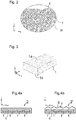
- Figure 2 illustrates a preferred inner structure of such a composite member 1, showing inside the circle an enlarged view of the cross section of the composite member 1 close to the surface thereof, as viewed in the longitudinal direction 1 of the composite member 1. The parts of the composite 1 not showed in Figure 7 have a similar structure.
- Figure 3 illustrates the composite member 1 three-dimensionally.
- the composite member 1 is made of composite material comprising reinforcing fibers f embedded in polymer matrix m.
- the reinforcing fibers f in the polymer matrix m are bound to each other with a polymer matrix m. This has been done e.g.
- the reinforcing fibers f are distributed substantially evenly in polymer matrix m and bound to each other by the polymer matrix m.
- the composite member 1 formed is a solid elongated rod-like one-piece structure.
- substantially all the reinforcing fibers f of each composite member 1 are parallel with the longitudinal direction of the composite member 1.
- the fibers f are also parallel with the longitudinal direction of the rope 2,2' as each composite member 1 are to be oriented parallel with the longitudinal direction of the rope 2,2'. This is advantageous for the rigidity as well as behavior in bending. Owing to the parallel structure, the fibers in the rope 2,2' will be aligned with the force when the rope 2,2' is pulled, which ensures that the structure provides high tensile stiffness.
- the composite member 1 can be inspected during the manufacturing of a rope, while the composite member 1 is naked of additional rope components, such as other composite members or substantial amount of coating around it. Then, to the composite member 1 can later, i.e. after said inspection, be attached additional rope components, such as other composite members or substantial amount of coating. Alternatively, the composite member 1 can be inspected while it already forms a part of a larger entity, i.e. a rope 2,2', and thereby has additional rope components attached thereto. Also when scanned together with other components described, a thermogram reveals without considerable disturbation the internal flaws or failures of the composite member 1.
- FIGs 4a and 4b illustrates each a completed rope 2,2' as viewed in longitudinal direction 1 of the composite member 1 and the rope 2,2'.
- Each rope 2,2' is belt-shaped. It is substantially larger in its width direction w than in its thickness direction t.
- elongated composite members 1 of the like illustrated in Figures 1 and 2 are embedded in a coating c forming the outer surface of the rope 2,2'.
- Each composite member 1 is parallel with the longitudinal direction of the rope 2,2'.
- Each composite member 1 continues unbroken throughout the length of the rope 2,2' forming a load bearing member of the rope 2,2'.
- the rope comprises plurality of composite members 1 adjacent each other in width direction of the rope 2,2', but alternatively it could comprise only one.
- the coating c is preferably made of polymer material.
- the coating c can be intended for protection of the composite members and/or facilitating contact with rope wheels and/or for positioning adjacent composite members 1 relative to each other, for example.
- the coating c is preferably furthermore preferably elastic, for which purpose the polymer material is preferably elastomer, such as polyurethane or silicon or rubber.
- the rope 2 of Figure 4a is more specifically such that it has a smooth outer surface without grooves or teeth.
- the rope 2' of Figure 4b is more specifically such that it has a contoured outer surface.
- the particular rope 2' illustrated in Figure 4b is grooved.
- the ribs r and grooves g are preferably suitable for lateral guiding of the rope 2' along a circumference of a rope wheel comprising a counterpart shape for said ribs r and grooves g of the rope 2'.
- the composite member 1 is preferably substantially larger in its width direction w than in its thickness direction t. This facilitates the inspection, because the temperature changing 200 can be performed via a flank 1a, 1b thereof, which flank 1a,1b faces in thickness direction of the composite member 1 and which is thereby large in area. Likewise, the scanning can be done in thickness direction t of the composite member 1, scanning a flank 1a, 1b thereof, which flank 1a,1b faces in thickness direction of the composite member 1, so the scanned area will be large in size and temperature deviations stand out clearly. To facilitate the temperature changing 200 and/or scanning 300, the width/thickness ratio of said composite member 1 is preferably more than 2.
- Figure 5 shows a cross section of a length of said elongated composite member 1 as viewed in width direction of the composite member 1.
- a humidity spot F' exists within the section of the composite member 1 illustrated.
- Figure 6 shows a thermographic image 4 taken in thickness direction of the composite member 1 of the section illustrated in Figure 5 .
- the thermographic image 4 reveals that the surface temperature is different at the point of the composite member 1 where the humidity spot F is located, compared to surface temperature of locations surrounding said point. In Figure 6 this is visible as a temperature deviation P.
- the temperature deviation P is in this case a temperature dip.
- Figure 7 shows a cross section of a length of said elongated composite member 1 as viewed in width direction of the composite member 1.
- a delamination spot F' exists within the section of the composite member 1 illustrated.
- Figure 8 shows a thermographic image 4 taken in thickness direction of the composite member 1 of the section illustrated in Figure 5 .
- the thermographic image 4 reveals that the surface temperature is different at the point of the composite member 1 where the delamination spot F' is located, compared to surface temperature of locations surrounding said point. This is because a discontinuation in the material, such as an airgap, will not conduct heat in same manner than solid construction. In Figure 8 this is visible as a temperature deviation P'.
- the surface temperature is lower at the point of the composite member 1 where the delamination spot F is located, compared to surface temperature of locations surrounding said point. Accordingly, the temperature deviation P' is in this case a temperature dip.
- said detecting temperature deviations P,P' comprises detecting temperature peaks and/or temperature dips, in the thermographic images of said elongated composite member 1. Then, preferably said detecting temperature peaks comprises detecting in the thermographic images areas where temperature exceeds a predetermined limit. Then, preferably said detecting temperature dips comprises detecting in the thermographic images areas where temperature is below a predetermined limit. In addition, or as an alternative to detecting said dips and/or peaks, preferably said detecting temperature peaks and/or temperature dips in the thermographic images comprises comparing zones of a thermographic image or thermographic images with each other.
- zones that are in longitudinal direction of said elongated composite member 1 from consecutive sections of the composite member 1 are compared, and said detecting comprises detecting substantial temperature differences between such zones, such as temperature differences of predetermined magnitude, i.e. temperature differences that exceed a predetermined threshold.
- the method further comprises performing one or more predefined actions when a temperature deviation P,P', such as a temperature peak or temperature dip is detected in the one or more thermographic images.
- Said one or more predefined actions may include one or more of producing an alarm signal; storing data indicating location of the elongated composite member 1 wherein a temperature deviation P,P', such as a temperature peak or temperature dip was detected; storing thermographic image(s) of the location of the elongated composite member 1 wherein a temperature deviation P,P', such as a temperature peak or temperature dip was detected and making a marking on the location of the elongated composite member 1 wherein a temperature deviation P,P', such as a temperature peak or temperature dip was detected.
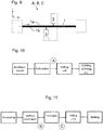
- Figure 9 illustrates a first preferred embodiment of the method.
- the method is performed during the manufacturing of a rope, such as a rope 2,2' illustrated in Figure 4a or 4b .
- the inspection can be carried out basically in any point of a manufacturing line of the rope 2,2' after formation of the composite member 1.
- the elongated composite member may or may not have a coating c.
- the elongated composite member 1 to be inspected is guided to run via a stationary inspection station A,B,C comprising said thermal imaging device 3. Said elongated composite member 1 passes past said thermal imaging device 3, which continuously or intermittently performs scanning of said elongated composite member 1.
- the whole length of the composite member 1 can be guided to run via a stationary inspection station A,B,C comprising said thermal imaging device 3 so the whole length thereof can be inspected.
- the method can this way be performed as an on-line inspection method in a factory in a manufacturing line of the rope 2,2' that the composite member 1 is to form part of.
- the temperature of said elongated composite member 1 is changed by cooling said elongated composite member 1 before the scanning 300 with a thermal imaging device 3.
- Figure 9 illustrates with broken line boxes the process steps preceding and following the inspection station A,B,C. Preferred details of these process steps are described later referring to Figures 10 and 11 .
- the stationary inspection station A,B,C can comprise a cooling device 5 arranged to cool the composite member 1 before it is guided to pass past said thermal imaging device 3, as illustrated in Figure 9 .
- a cooling device 5 arranged to cool the composite member 1 before it is guided to pass past said thermal imaging device 3, as illustrated in Figure 9 .
- said elongated composite member 1 or a rope 2,2' comprising said elongated composite member 1 is cooled with fluid of substantially lower temperature than the temperature of said elongated composite member 1.
- said fluid is sprayed or blown by a spraying or blowing machine against said elongated composite member 1, or a rope 2,2' comprising said elongated composite member 1 (if the composite member 1 is already part of a rope), in particular against the surface of said elongated composite member 1 or a rope 2,2' comprising said elongated composite member 1.
- Said fluid can be gaseous fluid, such as ambient air, or liquid.
- the deviations of temperature of the composite member 1 produced in flaw or failure spots within the composite member are best visible when the changing of temperature is swift so that the temperature differences do not have time to even out.
- the cooling is performed by aid of a cooling device 5.
- presence of a cooling device 5 is optional, because it is possible to make the ambient air to provide adequately swift and substantial cooling effect, e.g. by aid of high-speed movement of the composite member 1 itself.
- an elongated composite member 1 which has a high temperature, preferably such that a core temperature of the elongated composite member 1 is at least 50 Celsius degrees or more.
- Another advantage in cooling from a high temperatures is also that thus it is possible to achieve considerable cooling with simple means while avoiding unnecessary freezing of the composite member 1.
- Another advantage in cooling from a relatively high temperature is also that the heat accumulated in the composite member 1 can be utilized in the method.
- the composite member 1 is in a heated state, typically such that a core temperature of the elongated composite member 1 is at least 50 Celsius degrees or more. After one of these process stages, it is particularly preferable to carry out said temperature changing 200 and the subsequent scanning 300.
- Figure 10 illustrates a preferred point in the manufacturing line of the composite member 1, where the inspection station A is located, and thus where the temperature changing 200 by cooling and the subsequent scanning 300 with the thermal imaging device 3 is to be performed.
- heat accumulated in said elongated composite member 1 during manufacturing process of said elongated composite member 1 is removed from said elongated composite member 1.
- the aforementioned method step of providing 100 an elongated composite member 1 comprises in this embodiment forming said elongated composite member 1, particularly by pultrusion where reinforcing fibers f are embedded in a matrix material m and driven through a die. Then, in said cooling heat accumulated in said forming (by pultrusion) is removed from said elongated composite member 1.
- the changing 200 of the temperature by cooling and the subsequent scanning 300 are then performed right after the forming, i.e. in this case pultrusion, but at least before winding of the composite member 1 on a reel because these steps are performed in the manufacturing line of the composite member 1.
- the elongated composite member does not have a coating c yet at the time when the steps 200 and 300 are performed.
- Figure 11 illustrates a preferred point in the manufacturing line of the rope 2,2', in which point the inspection station B,C is located, and thus where the temperature changing 200 by cooling and the subsequent scanning 300 with the thermal imaging device 3 is to be performed.
- the composite member 1 has already been formed earlier.
- heat accumulated in said elongated composite member 1 during manufacturing process of said elongated composite member 1 is removed from said elongated composite member 1. This can be simply done by locating an inspection station B after a surface treatment station, or by locating an inspection station C after an extrusion station.
- the manufacturing process of the rope 2,2' comprises surface treatment of said elongated composite member 1, such as plasma treatment, wherein temperature of said elongated composite member 1 rises. At least part of the aforementioned accumulated heat to be removed has been accumulated in said elongated composite member 1 in said surface treatment. In other words, in said cooling heat accumulated in said surface treatment is removed from said elongated composite member 1.
- the changing of temperature 200 by cooling and the subsequent scanning 300 are then performed after the surface treatment and before the following process for applying of a coating c on the composite member 1, i.e. in this case extrusion.
- the inspection stations B the elongated composite member does not have a coating c yet at the time when the steps 200 and 300 are performed.
- the manufacturing process of the rope 2,2' comprises applying of heated coating c, eg. having temperature over 100 deg Celsius, on said elongated composite member 1, such as by extrusion coating, in which applying temperature of said elongated composite member 1 rises. At least part of the aforementioned accumulated heat to be removed has been accumulated in said elongated composite member 1 in said applying, said applying preferably being in the form of extrusion coating. In other words, in said cooling heat accumulated in said applying of heated coating c is removed from said elongated composite member 1.
- heated coating c eg. having temperature over 100 deg Celsius
- the changing of temperature 200 by cooling and the subsequent scanning 300 are then performed after the applying of heated coating on said elongated composite member 1, and before the following step of winding the rope 2,2' on a reel, because these steps are performed in the manufacturing line of the rope 2,2'.
- the inspection station C With the inspection station C, the elongated composite member already has a coating c at the time when the step 300 is performed.
- said cooling comprises directing cooling from one side of said elongated composite member 1 on a flank 1b of the composite member 1 that faces away from the thermal imaging device 3, as illustrated in Figure 9 for instance.
- the cooling and scanning 300 are performed from opposite lateral sides of the composite member 1. Said changing 200 the temperature of said elongated composite member 1 and said scanning 300 are directed on opposite flanks 1a,1b of said elongated composite member 1. Thereby, in the scanning 300 the effect of the cooling from the opposite side will be seen. Any flaws or failures, such as delaminations, large voids, holes etc., that affect through-thickness thermal conductivity of the composite member 1 will be seen as deviations of temperature of the composite member 1. Defects in the coating on the detector side can also detected.
- Figure 12 illustrates a second preferred embodiment of the method.
- the method is performed during the manufacturing of a rope, such as a rope 2,2' illustrated in Figure 4a or 4b .
- the inspection can be carried out basically in any point of a manufacturing line of the rope 2,2' after formation of the elongated composite member 1.
- the elongated composite member may or may not have a coating c.
- the elongated composite member 1 to be inspected is guided to run via a stationary inspection station D, E, F, G, H, I comprising said thermal imaging device 3.
- Said elongated composite member 1 passes past said thermal imaging device 3, which continuously or intermittently performs scanning of said elongated composite member 1.
- the whole length of the composite member 1 can be guided to run via a stationary inspection station D, E, F, G, H, I comprising said thermal imaging device 3 so the whole length thereof can be inspected.
- the method can this way be performed as an on-line inspection method in a factory in a manufacturing line of the rope 2,2' that the composite member 1 is to form part of.
- the temperature of said elongated composite member 1 is changed by heating said elongated composite member 1 before the scanning 300 with a thermal imaging device 3.
- Figure 9 illustrates with broken line boxes the process steps preceding and following the inspection station D, E, F, G, H, I. Preferred details of these process steps are described later referring to Figures 13 and 14 .
- the stationary inspection station D, E, F, G, H, I can comprise a heating device 6 arranged to heat the composite member 1 before it is guided to pass past said thermal imaging device 3, as illustrated in Figure 12 .
- said heating comprises electromagnetic induction heating, in which case the heating device 6 of Figure 12 is an electromagnetic induction heater.
- said heating comprises directing heating from one side of said elongated composite member 1 on a flank 1b of the composite member 1 that faces away from the thermal imaging device 3, as illustrated in Figure 12 for instance.
- the heating and scanning 300 are performed from opposite lateral sides of the composite member 1.
- Said changing 200 the temperature of said elongated composite member 1 and said scanning 300 are directed on opposite flanks 1a,1b of said elongated composite member 1.
- Any flaws or failures, such as delaminations, large voids, holes etc., that affect through-thickness thermal conductivity of the composite member 1 will be seen as deviations of temperature of the composite member 1. Defects in the coating on the detector side can also detected.
- Said induction heating most preferably comprises heating by pulsed phase thermography (PPT), such as pulsed phase thermography using a planar coil optimized for the anisotropic conductivity of the composite member.
- PPT pulsed phase thermography
- Induction frequency is preferably 5-20 MHz whereby the coating, if any, can be penetrated and the induced currents can be concentrated on the flank surface (skin effect). This gives pulses of heat that traverse across the thickness of the specimen and are imaged on the other side.
- Figure 13 illustrates two preferred alternative points in the manufacturing line of the composite member 1, where the inspection station D,E is to be located, and thus where the temperature changing 200 by heating and the subsequent scanning 300 with the thermal imaging device 3 is to be performed.
- said temperature changing 200 by heating is preferably performed by aid of a heating device 6.
- the aforementioned method step of providing 100 an elongated composite member 1 comprises in this embodiment forming said elongated composite member 1, particularly by pultrusion where reinforcing fibers f are embedded in a matrix material m and driven through a die.
- the aforementioned method steps of changing 200 by heating and the subsequent scanning 300 are in this embodiment performed after the forming, i.e. in this case pultrusion.
- the steps are performed in the manufacturing line of the composite member 1, so they are performed before winding of the composite member 1 on a reel.
- the elongated composite member does not have a coating c yet at the time when the steps 200 and 300 are performed.
- Figure 14 illustrates four preferred alternative points in the manufacturing line of the rope 2,2', where the inspection station F,G,H,I is to be located, and thus where the scanning 300 with the thermal imaging device 3 is to be performed.
- the composite member 1 has already been formed earlier.
- the inspection stations F and G the elongated composite member does not have a coating c yet at the time when the steps 200 and 300 are performed.
- the inspection stations H and I the elongated composite member 1 already has a coating c at the time when the step 300 is performed.
- said temperature changing 200 by heating is preferably performed by aid of a heating device 6.
- presence of a separate heating device can be omitted if a process stage preceding the inspection station itself comprises a heating device which can heat the composite member 1 such that the temperature change can be used for detection of temperature deviations P,P' in thermographic images of the composite member 1.
- said changing 200 the temperature of said elongated composite member 1 by heating can comprise a step of manufacturing process of the rope 2,2', wherein temperature of said elongated composite member 1 rises.
- said step of manufacturing process of the rope 2,2', wherein temperature of said elongated composite member 1 rises can be pultrusion. This can be implemented by locating the inspection station in point D in Figure 13 .
- said step of manufacturing process of the rope 2,2', wherein temperature of said elongated composite member 1 rises can be a surface treatment of said elongated composite member 1, such as plasma treatment or alternatively applying of hot coating on said elongated composite member 1, such as by extrusion coating.
- a surface treatment of said elongated composite member 1 such as plasma treatment or alternatively applying of hot coating on said elongated composite member 1, such as by extrusion coating.
- said changing 200 the temperature of said elongated composite member 1 by heating or cooling said elongated composite member 1 particularly via a flank 1a,1b thereof is advantageous as it enables that said changing 200 of the temperature needs to be directed on only a length of said elongated composite member 1 at a time, which length is substantially shorter than the overall length of the elongated composite member 1, preferably less than 10 % of the overall length of the elongated composite member 1.
- the inspection can be performed for a very short length of the composite member 1, whereby only small part of the manufacturing process of the rope will be affected by the inspection.
- the inspection method described is advantageous because it can be performed in a small space and without considerably disturbing the surroundings of the section under inspection, such as other parts of the manufacturing process. Moreover, the method is advantageously simple to implement, and it can be performed energy efficiently.
- Using the flank 1a,1b also provides that the temperature changing 200 can be performed utilizing heat generated in the manufacturing process, but also that cooling can be used, instead of heating for producing a temperature change.
- the composite member 1 is preferably more specifically as described hereinafter.
- the fibers f are preferably substantially untwisted in relation to each other, which provides them said orientation parallel with the composite member 1, and finally so with the longitudinal direction of the rope 2,2' as well.
- the reinforcing fibers f are preferably long continuous fibers in the longitudinal direction of the elongated composite member 1, preferably continuing unbroken throughout the whole length of the elongated composite member 1.
- the reinforcing fibers f are preferably distributed in the matrix m substantially evenly.
- the fibers f are then arranged so that the composite member 1 would be as homogeneous as possible in the transverse direction thereof. Owing to the even distribution, the fiber density in the cross-section of the elongated composite member 1 is substantially constant.
- the composite matrix m into which the individual fibers f are distributed, is most preferably made of epoxy, which has good adhesiveness to the reinforcement fibers f and which is known to behave advantageously with reinforcing fibers such as carbon fiber particularly.
- reinforcing fibers such as carbon fiber particularly.
- polyester or vinyl ester can be used, but any other suitable alternative materials can be used.
- the matrix m has been applied on the fibers f such that a chemical bond exists between each individual reinforcing fiber f and the matrix m. Thereby a uniform structure is achieved.
- each fiber can have a thin coating, e.g.
- the properties of the polymer matrix m can also be optimized as it is common in polymer technology.
- the matrix m can comprise a base polymer material (e.g. epoxy) as well as additives, which fine-tune the properties of the base polymer such that the properties of the matrix are optimized.
- the polymer matrix m is preferably of a hard non-elastomer, such as said epoxy, as in this case a risk of buckling can be reduced for instance.
- the polymer matrix need not be non-elastomer necessarily, e.g. if the downsides of this kind of material are deemed acceptable or irrelevant for the intended use.
- the polymer matrix m can be made of elastomer material such as polyurethane or rubber for instance.
- the matrix m of the elongated composite member 1 is most preferably hard in its material properties.
- a hard matrix m helps to support the reinforcing fibers f, especially when the rope bends, preventing buckling of the reinforcing fibers f of the bent rope, because the hard material supports the fibers f efficiently.
- the polymer matrix m is hard, and in particular non-elastomeric.
- the most preferred materials for the matrix are epoxy resin, polyester, phenolic plastic or vinyl ester.
- the polymer matrix m is preferably such that its modulus of elasticity E is over 2 GPa, most preferably over 2.5 GPa.
- the modulus of elasticity E is preferably in the range 2.5-10 GPa, most preferably in the range 2.5-4.5 GPa.
- the matrix m which can provide these material properties.
- Preferably over 50% proportion of the area of the cross-section of the elongated composite member 1 is of the aforementioned reinforcing fiber, preferably such that 50%-80% proportion is of the aforementioned reinforcing fiber, more preferably such that 55%-70% proportion is of the aforementioned reinforcing fiber, and substantially all the remaining area is of polymer matrix m. Most preferably, this is carried out such that approx. 60% of the area is of reinforcing fiber and approx. 40% is of matrix material (preferably epoxy material).
- the elongated composite member 1 is preferably completely non-metallic, i.e. made not to comprise metal.
- a rope 2,2' is manufactured, which comprises one or more composite members 1 as load bearing members of the rope 2,2', said elongated composite member 1 comprising non-metallic reinforcing fibers f embedded in polymer matrix m, said reinforcing fibers preferably being carbon fibers or glass fibers.
- An embodiment of the rope 2,2' is illustrated in Figure 4 .
- the rope 2,2' manufactured is such that each composite member 1 continues unbroken throughout the length of the rope 2,2'.
- the rope 2,2' manufactured is such that each composite member 1 is parallel with the longitudinal direction of the rope 2,2'.
- an elongated composite member 1 is formed.
- the method for manufacturing the hoisting rope 2,2' comprises inspecting quality and/or condition of one or more of the elongated composite members 1 with a method as described above. Accordingly, inspecting quality and/or condition of one or more of the elongated composite members 1 is performed during the manufacturing of the rope 2,2'. Preferred details of the manufacturing process have been illustrated in Figures 10-11 and 13-14 .
- an advantageous shape of the composite member 1 and an advantageous shape and internal layout of the rope 2,2' have been disclosed.
- the invention can also be utilized with differently shaped composite members and with ropes which comprise differently shaped composite members or a different number of them.
- the method, and the various embodiments thereof presented, can be used to obtain one or more advantages mentioned in the application.
- the methods can for instance be used to reveal the location and the kind of damage of a composite member very accurately.
- the methods can be used for catching manufacturing errors, to monitor quality within or at the end of the rope production line.
- the methods can be used to evaluate possible rope component damage before elevator installation (if, for example, rope has been damaged during transport and damage is seen visually).
- the methods can be also used to evaluate rope condition during regular maintenance of an elevator. It is not necessary that the method is performed as part of a manufacturing process of the rope. In its broadest sense, the method can be also used to inspect composite member(s) of a rope already forming part of an elevator.
- said changing 200 the temperature of said elongated composite member 1 and said scanning 300 can be directed on opposite flanks 1a,1b of said elongated composite member 1. Any flaws or failures affect through-thickness thermal conductivity of the composite member 1 will be seen as deviations of temperature of the composite member 1.
- This kind of implementation is however not necessary, because alternatively said changing the temperature of said elongated composite member 1 and said scanning can be directed on the same flank of said elongated composite member, in which case reflections of temperature changes, such as reflections of heat waves, can be detected in the thermographic images created based on output of said scanning.
- heating effect has been described.
- the aforementioned heating could be performed by bending the composite member rapidly one or more times, or by producing vibration in the composite member particularly to cause more heating around highly stressed areas (defective areas).
- mechanical loading can be used for adiabatically heating the composite member.
- the core temperature of the elongated composite member 1, when starting said temperature changing by cooling is relatively high. This is however not necessary, particularly when low temperature is acceptable. Cooling as far as to zero Celsius degrees or below, is advantageous if more clear deviations are wanted.
- the contrast generated by differences in volumetric heat capacity would be much higher if a phase transition is introduced. If there is a water inclusion inside the composite member 1, and the water undergoes a phase transition, a significant improvement in thermal contrast is achieved.
- the phase transition could likewise be used in the embodiment where said temperature changing is performed by heating. Then, the core temperature of the elongated composite member 1, when starting said heat changing by heating, is zero Celsius degrees or below so that water inside the composite member 1 would undergo a phase transition in the heating.
- the method steps can additionally or alternatively be used for inspecting quality and/or condition of a coating provided on an elongated member 1, which may, or may not, be a composite member as described above. This may be advantageous particularly when the coating c has a complicated contoured structure, such as grooved structure illustrated in Figure 4b . It is to be understood that the above description and the accompanying Figures are only intended to teach the best way known to the inventors to make and use the invention. It will be apparent to a person skilled in the art that the inventive concept can be implemented in various ways.
Landscapes
- Chemical & Material Sciences (AREA)
- Immunology (AREA)
- Pathology (AREA)
- Health & Medical Sciences (AREA)
- Analytical Chemistry (AREA)
- Biochemistry (AREA)
- General Health & Medical Sciences (AREA)
- General Physics & Mathematics (AREA)
- Physics & Mathematics (AREA)
- Life Sciences & Earth Sciences (AREA)
- Investigating Or Analyzing Materials Using Thermal Means (AREA)
- Ropes Or Cables (AREA)
- Mechanical Engineering (AREA)
- Engineering & Computer Science (AREA)
- Composite Materials (AREA)
- Testing Of Devices, Machine Parts, Or Other Structures Thereof (AREA)
- Lift-Guide Devices, And Elevator Ropes And Cables (AREA)
- Support Of The Bearing (AREA)
Abstract
Description
- The invention relates to inspecting condition of an elongated composite member of a rope of a hoisting apparatus. The hoisting apparatus is preferably an elevator for vertically transporting passengers and/or goods.
- In hoisting devices such as elevators, one or more ropes are used as the means by which the load to be hoisted is suspended. Each elevator rope typically includes one or more load bearing members that are elongated in the longitudinal direction of the rope, each forming a structure that continues unbroken throughout the length of the rope. Load bearing members are the members of the rope which are able to bear together the load exerted on the rope in its longitudinal direction. The load, such as a weight suspended by the rope, causes tension on the load bearing member, which tension can be transmitted by the load bearing member in question all the way from one end of the rope to the other end of the rope. Ropes may further comprise non-bearing components, such as a coating, which cannot transmit tension in the above described way. The coating can be utilized for protection of the load bearing members and/or facilitating contact with rope wheels and/or for positioning adjacent load bearing members relative to each other, for example.
- Such ropes exist, where the load bearing members are made of composite material wherein reinforcing fibers are embedded in a polymer matrix. Such load bearing members are structurally very different, when compared to conventional steel rope technology. Therefore, they are also prone to different kind of defects, caused already in manufacturing or degradation in use. These typically appear as transverse cracking of the matrix and/or the fibres or internal delamination of the load bearing member in longitudinal direction of the load bearing member. Beside delamination and cracks, other examples of significant flaws in composites are: voids, porosity, inclusions, wear, impact damage, incorrect cure and fibre breakage, wrinkling or waviness. Many of the flaws and failures occur first without being detrimental for the integrity of the structure. Accumulation of structural failures under load results leads in a progressively increasing number of detectable failures before final catastrophic failure.
- In prior art, the quality and/or condition of the composite load bearing members has been inspected by monitoring electrical properties of the load bearing members, such as the resistance of a circuit formed partially by the load bearing members or the resistance of a circuit formed partially by conductor wires embedded inside the load bearing members.
- It has been now found out that prior art inspection methods, such as those monitoring electric properties, do not reliably reveal all kinds of defects in fiber-composite members.
- The object of the invention is to introduce an improved method whereby quality and/or condition of an elongated composite member can be inspected, which elongated composite member is a load bearing member of a rope of a hoisting apparatus, such as an elevator, or a precursor of such a load bearing member. An object is to introduce a solution by which one or more of the above defined problems of prior art and/or problems discussed or implied elsewhere in the description can be solved. An object is particularly to introduce a solution by which initial flaws or failures inside a composite member can be detected, localized and reacted to before they become catastrophic. An object is to introduce such solutions which are simply usable as part of the manufacturing process before completion of the product, as well as solutions usable for inspection of a completed product. Embodiments are presented, inter alia, which enable detection of the size, shape, orientation and type of the initial flaws or failures inside the elongated composite member. Embodiments are presented, inter alia, by which particularly delamination of internal structures of the elongated composite member can be effectively be detected, localized and reacted to.
- It is brought forward a new method for inspecting quality and/or condition of an elongated composite member, which is a load bearing member of a rope of a hoisting apparatus, such as an elevator, or a precursor of such a load bearing member, the method comprising providing an elongated composite member; and changing the temperature of said elongated composite member by heating or cooling said elongated composite member via a flank thereof; and scanning said elongated composite member from a lateral side thereof with a thermal imaging device after said changing of the temperature; and creating thermographic images of said elongated composite member. With this solution one or more of the above mentioned objects can be achieved. Preferable further details are introduced in the following, which further details can be combined with the method individually or in any combination.
- In a preferred embodiment, said elongated composite member comprises non-metallic reinforcing fibers embedded in a polymer matrix, said reinforcing fibers preferably being carbon fibers or glass fibers. Quality and/or condition inspection by the method as defined is particularly advantageous with composite members as defined, because they are fragile and sensitive to formation of internal flaws or failures that are otherwise difficult to notice and localize.
- In a preferred embodiment, the method further comprises, after said creating, detecting temperature deviations, such as temperature peaks and/or temperature dips, in the thermographic images of said elongated composite member. Then, preferably said detecting temperature peaks comprises detecting in the thermographic images areas where temperature exceeds a predetermined limit. Then, preferably said detecting temperature dips comprises detecting in the thermographic images areas where temperature is below a predetermined limit. In addition, or as an alternative to detecting said dips and/or peaks, preferably said detecting temperature peaks and/or temperature dips in the thermographic images comprises comparing zones of a thermographic image or thermographic images with each other. In said comparing, zones that are in longitudinal direction of said elongated composite member from consecutive sections of the composite member are compared, and said detecting comprises detecting substantial temperature differences between such zones, such as temperature differences of predetermined magnitude, i.e. temperature differences that exceed a predetermined threshold.
- In a preferred embodiment, said detecting temperature deviations is performed by a computer.
- In a preferred embodiment, the method further comprises performing one or more predefined actions when a temperature deviation, such as a temperature peak or temperature dip, is detected in the thermographic images. Said one or more predefined actions include one or more of producing an alarm signal, storing data indicating location of the elongated composite member wherein a temperature deviation such as a temperature peak or temperature dip was detected, storing thermographic image(s) of the location of the elongated composite member wherein temperature deviation such as a temperature peak or temperature dip was detected, making a marking on the location of the elongated composite member wherein temperature deviation such as a temperature peak or temperature dip was detected.
- In a preferred embodiment, the composite member is substantially larger in its width direction than in its thickness direction. This facilitates use of a flank of the composite member for the temperature changing and/or the scanning. This advantage is considerable particularly when the width/thickness ratio said composite member is substantially greater than one, such as more than 2.
- In a preferred embodiment, the changing of the temperature is performed via a flank of the composite member, which flank faces in thickness direction of the composite member.
- In a preferred embodiment, the scanning is performed in thickness direction of the composite member, scanning a flank thereof, which flank faces in thickness direction of the composite member. Thus, the scanned area will be large in size and temperature deviations stand out clearly. To facilitate the temperature changing and/or scanning, the width/thickness ratio said composite member is preferably more than 2.
- In a preferred embodiment, said elongated composite member is scanned while it is in a heated state produced by said heating or in a cooled state produced by said cooling, respectively.
- In a preferred embodiment, said changing the temperature of said elongated composite member is directed on only a length of said elongated composite member at a time, which length is substantially shorter than the overall length of the elongated composite member, preferably less than 10 % of the overall length of the elongated composite member.
- In a preferred embodiment, the method is performed during the manufacturing of the rope. Preferably, the method is performed as an on-line inspection method in the manufacturing line of the composite member or the rope. Preferably, the method is performed in a factory manufacturing ropes or composite members therefor.
- In a preferred embodiment, said elongated composite member is guided to run via a stationary inspection station comprising said thermal imaging device. Preferably, said elongated composite member is arranged to pass past said thermal imaging device, which continuously or intermittently performs scanning of said elongated composite member.
- In a preferred embodiment, in said changing, the temperature of said elongated composite member is changed by cooling said elongated composite member.
- In a preferred embodiment utilizing cooling, in said providing, an elongated composite member is provided which has a core temperature at least 50 Celsius degrees or more. Particularly, the core temperature is at least 50 Celsius degrees or more when starting said changing.
- In a preferred embodiment utilizing cooling, in said cooling heat accumulated in said elongated composite member during manufacturing process of said elongated composite member or a rope comprising said elongated composite member is removed from said elongated composite member. In this case, one preferred option is that said providing comprises forming said elongated composite member, preferably by pultrusion, and at least part of said heat accumulated in said elongated composite member has been accumulated in said elongated composite member in said forming (by pultrusion). Another preferred option is that the manufacturing process of the rope comprises surface treatment of said elongated composite member, such as plasma treatment, wherein temperature of said elongated composite member rises, and at least part of said heat accumulated has been accumulated in said elongated composite member in said surface treatment. A third preferred option is that the manufacturing process (of the rope) comprises applying of heated coating, eg. having temperature over 100 deg Celsius, on said elongated composite member, such as by extrusion coating, and at least part of said heat accumulated has been accumulated in said elongated composite member in said applying, preferably said extrusion coating.
- In a preferred embodiment utilizing cooling, said cooling is performed by aid of a cooling device. Using a device for producing the temperature change is advantageous so that the temperature change produced in the composite member can be space-efficiently achieved, simply controlled, and the response is adequately swift and substantial to enable easy detection of temperature deviations in the thermographic images of said elongated composite member.
- In a preferred embodiment utilizing cooling, in said cooling said elongated composite member or a rope comprising said elongated composite member is cooled with fluid of substantially lower temperature than the temperature of said elongated composite member. Preferably, said fluid is sprayed or blown against the said elongated composite member or a rope comprising said elongated composite member by a spraying or blowing machine, in particular against the surface of said elongated composite member or a rope comprising said elongated composite member. Said fluid is preferably gaseous fluid, such as ambient air, but alternatively it can be liquid.
- In a preferred embodiment utilizing heating, in said changing the temperature of said elongated composite member is changed by heating said elongated composite member.
- In one kind of preferred embodiment utilizing heating, said heating comprises a step of manufacturing process of the rope, wherein temperature of said elongated composite member rises. In this case, one preferred option is that said step of manufacturing process of the rope is a surface treatment of said elongated composite member, such as plasma treatment. Another preferred option is that said step of manufacturing process of the rope is forming of said elongated composite member by pultrusion. A third preferred option is that said step of manufacturing process of the rope is applying of hot coating on said elongated composite member, such as by extrusion coating.
- In another kind of preferred embodiment utilizing heating, said heating is performed by aid of a heating device. Using a device for producing the temperature change is advantageous so that the temperature change produced in the composite member can be space-efficiently achieved, simply controlled, and the response is adequately swift and substantial to enable easy detection of temperature deviations in the thermographic images of said elongated composite member. Said heating device can be an induction heater, for example. In this case, said heating comprises electromagnetic induction heating. Alternatively, said heating device could be a flash light heater. Generally, said heating can comprise heating by pulses. Then, said heating can comprise heating by pulsed phase thermography (PPT). Alternatively, said heating could comprise flash light pulsing. Heating by pulses facilitates detection of flaws or failures as these will cause a local phase shift in the heat waves. Then, the detection temperature deviations can comprises detection of local phase shift in the heat waves. This step of the detection can be most simply implemented by a computer.
- In a preferred embodiment utilizing heating or cooling, said heating or cooling comprises directing heating or cooling from one side of said elongated composite member, and in said scanning said elongated composite member is scanned with a thermal imaging device from the opposite side.
- In a preferred embodiment, said changing the temperature of said elongated composite member, i.e. said heating or cooling, and said scanning are directed on opposite flanks of said elongated composite member.
- In a preferred embodiment, the reinforcing fibers are distributed substantially evenly in the polymer matrix. They are bound to each other by the polymer matrix. Furthermore, preferably, over 50% of the cross-sectional square area of the composite member consists of said reinforcing fibers. Thereby, load bearing ability with high tensile stiffness can be facilitated. The reinforcing fibers f are preferably long continuous fibers in the longitudinal direction of the elongated composite member, preferably continuing unbroken throughout the whole length of the elongated composite member. Preferably, substantially all the reinforcing fibers f of each composite member are parallel with the longitudinal direction of the composite member. The composite member formed is a solid elongated rod-like one-piece structure.
- In a preferred embodiment, the composite member is inspected either naked of additional rope components, such as other composite members or substantial amount of coating, or while it has additional rope components attached thereto, said additional rope components including one or more composite members and/or a coating. In the latter case, the composite member is comprised in a rope and embedded in a coating forming the outer surface of the rope and said scanning is performed through the coating. The coating is preferably made of polymer material. Presence of the coating on the composite member may be in some cases advantageous as in this way defects in the coating can also detected. Then, the method is used also to inspect quality and/or condition of the coating. This may be advantageous particularly when the coating has a complicated contoured structure, such as grooved structure.
- In a preferred embodiment, water phase transition is utilized for increasing the thermal contrast. When utilizing heating for said temperature changing, the core temperature of the elongated
composite member 1, when starting said heat changing by heating, is zero Celsius degrees or below, and in said heating the core temperature of the elongatedcomposite member 1 is brought substantially, such as plurality of degrees, above zero Celsius degrees so that water inside thecomposite member 1 would undergo a phase transition in the heating. Correspondingly, when utilizing cooling for said temperature changing the core temperature of the elongatedcomposite member 1, when starting said heat changing by cooling, is substantially, such as plurality of degrees, above zero Celsius degrees, and in said cooling the core temperature of the elongated composite member is brought to zero Celsius degrees or below, so that water inside the composite member would undergo a phase transition in the cooling. - It is also brought forward a new method for manufacturing a hoisting rope of a hoisting apparatus, such as an elevator, which rope comprises one or more composite members as load bearing members of the rope, said elongated composite member preferably comprising non-metallic reinforcing fibers embedded in polymer matrix, said reinforcing fibers preferably being carbon fibers or glass fibers, the method comprising inspecting quality and/or condition of one or more of the elongated composite members with a method as defined anywhere above or elsewhere in the application such as in the claims. With this solution one or more of the above mentioned objects can be achieved. Preferable further details have been introduced above and in the following, which further details can be combined with the method individually or in any combination.
- In a preferred embodiment, the method comprises forming said elongated composite member.
- In a preferred embodiment, said forming comprises pultrusion, in particular pultrusion of the reinforcing fibers and fluid material of the polymer matrix through a die.
- In a preferred embodiment, the method further comprises applying coating on the composite member. The coating can be applied on more than one of said composite members whereby a rope containing more than one composite members as load bearing members embedded in common coating can be manufactured.
- Preferably, said rope is such that each composite member continues unbroken throughout the length of the rope.
- Preferably, said rope is such that each composite member is parallel with the longitudinal direction of the rope.
- In a preferred embodiment, the rope is a suspension rope of an elevator for suspending an elevator car.
- It is also brought forward a new arrangement for inspecting quality and/or condition of an elongated composite member, which is a load bearing member of a rope of a hoisting apparatus, such as an elevator, or a precursor of such a load bearing member. The arrangement is arranged to change the temperature of an elongated composite member by heating or cooling said elongated composite member via a flank thereof; and scan said elongated composite member from a lateral side thereof with a thermal imaging device after said changing of the temperature; and create thermographic images of said elongated composite member. Preferably, said elongated composite member comprises non-metallic reinforcing fibers embedded in a polymer matrix, said reinforcing fibers preferably being carbon fibers or glass fibers. With this solution one or more of the above mentioned objects can be achieved. The arrangement is preferably arranged to perform further method steps as described in the above. The arrangement can be arranged to perform individual further method steps as described in the above or plurality of method steps as described in the above in any combination, particularly to achieve advantages related to the method step(s) in question. The arrangement is preferably either an arrangement of inspecting quality and/or condition of an elongated composite member during manufacturing of a rope or an arrangement of inspecting quality and/or condition of an elongated composite member already forming part of an elevator.
- In the following, the present invention will be described in more detail by way of example and with reference to the attached drawings, in which
-
Figure 1 illustrates steps of an embodiment of a method for inspecting quality and/or condition of an elongated composite member. -
Figure 2 illustrates a preferred inner structure of the elongated composite member. -
Figure 3 illustrates preferred embodiment of the elongated composite member three-dimensionally. -
Figure 4a illustrates preferred embodiment of a belt-shaped rope of a first kind comprising elongated composite members. -
Figure 4b illustrates preferred embodiment of a belt-shaped rope of a second kind comprising elongated composite members. -
Figure 5 illustrates a cross section of a section of an elongated composite member as viewed in width direction of the elongated composite member, wherein a humidity spot exists inside the elongated composite member. -
Figure 6 illustrates a thermographic image taken in thickness direction of the composite member of the section illustrated inFigure 5 . -
Figure 7 illustrates a cross section of a section of an elongated composite member as viewed in width direction of the elongated composite member, wherein a delamination spot exists inside the elongated composite member. -
Figure 8 illustrates a thermographic image taken in thickness direction of the composite member of the section illustrated inFigure 7 . -
Figure 9 illustrates a first preferred embodiment of an arrangement implementing the method. -
Figure 10 illustrates a preferred point in the manufacturing line of the composite member where an inspection station can be located. -
Figure 11 illustrates preferred alternative points in the manufacturing line of the rope where an inspection station can be located. -
Figure 12 illustrates a second preferred embodiment of an arrangement implementing the method. -
Figure 13 illustrates preferred alternative points in the manufacturing line of the composite member where an inspection station can be located. -
Figure 14 illustrates preferred alternative points in the manufacturing line of the rope where an inspection station can be located. - The foregoing aspects, features and advantages of the invention will be apparent from the drawings and the detailed description related thereto.
-
Figure 1 illustrates steps of a preferred embodiment of a method for inspecting quality and/or condition of an elongatedcomposite member 1, which is a load bearing member of arope 2,2' of a hoisting apparatus, such as an elevator, or a precursor of such a load bearing member. The method comprises providing 100 an elongatedcomposite member 1, said elongatedcomposite member 1 being made of composite material comprising non-metallic reinforcing fibers f embedded in polymer matrix m, said reinforcing fibers preferably being carbon fibers or glass fibers. The elongatedcomposite member 1 is a load bearing member of arope 2,2' of a hoisting apparatus, such as an elevator, or a precursor of such a load bearing member. After this, the method comprises changing 200 the temperature of said elongatedcomposite member 1 substantially by heating or cooling from a lateral side thereof said elongatedcomposite member 1 via aflank composite member 1 relative to the longitudinal direction of the elongatedcomposite member 1. Preferably, thecomposite member 1 is substantially larger in its width direction w than in its thickness direction t, and said transverse direction is thickness direction t of thecomposite member 1. After changing 200 the temperature of said elongatedcomposite member 1, the method comprises scanning 300 said elongatedcomposite member 1 from a lateral side thereof with athermal imaging device 3. In thescanning 300, said elongatedcomposite member 1 is scanned while it is in a heated state produced by said heating or in a cooled state produced by said cooling, respectively. The method furthermore comprises a step of creating 400thermographic images 4, so called thermograms, of said elongatedcomposite member 1 based on output of said scanning. A thermographic image reveals uneven changing of temperature, if there are temperature peaks or dips within the scanned length of thecomposite member 1. In general, it is possible to perform said changing 200 the temperature of said elongatedcomposite member 1 by heating or cooling using any known way, such as utilizing convection, conduction, radiation or induction, for example. - Preferably, the method further comprises, after said creating 400
thermographic images 4, detecting temperature peaks or temperature dips in thethermographic images 4 of said elongatedcomposite member 1. This detecting is preferably performed by a computer, whereby automatic execution of the method is facilitated. Thus, the method can be implemented as an automated on-line inspection method forming a part of a production line of arope 2,2', for instance. - Said reinforcing fibers f are most preferably carbon fibers, but alternatively they can be glass fibers, or possibly some other fibers.
Figure 2 illustrates a preferred inner structure of such acomposite member 1, showing inside the circle an enlarged view of the cross section of thecomposite member 1 close to the surface thereof, as viewed in thelongitudinal direction 1 of thecomposite member 1. The parts of the composite 1 not showed inFigure 7 have a similar structure.Figure 3 illustrates thecomposite member 1 three-dimensionally. Thecomposite member 1 is made of composite material comprising reinforcing fibers f embedded in polymer matrix m. The reinforcing fibers f in the polymer matrix m are bound to each other with a polymer matrix m. This has been done e.g. in an earlier manufacturing phase by immersing them together in the fluid material of the polymer matrix which is thereafter solidified. Said immersing can be done in the form of pultrusion through a die. The reinforcing fibers f are distributed substantially evenly in polymer matrix m and bound to each other by the polymer matrix m. Thecomposite member 1 formed is a solid elongated rod-like one-piece structure. Preferably, substantially all the reinforcing fibers f of eachcomposite member 1 are parallel with the longitudinal direction of thecomposite member 1. Thereby, the fibers f are also parallel with the longitudinal direction of therope 2,2' as eachcomposite member 1 are to be oriented parallel with the longitudinal direction of therope 2,2'. This is advantageous for the rigidity as well as behavior in bending. Owing to the parallel structure, the fibers in therope 2,2' will be aligned with the force when therope 2,2' is pulled, which ensures that the structure provides high tensile stiffness. - The
composite member 1 can be inspected during the manufacturing of a rope, while thecomposite member 1 is naked of additional rope components, such as other composite members or substantial amount of coating around it. Then, to thecomposite member 1 can later, i.e. after said inspection, be attached additional rope components, such as other composite members or substantial amount of coating. Alternatively, thecomposite member 1 can be inspected while it already forms a part of a larger entity, i.e. arope 2,2', and thereby has additional rope components attached thereto. Also when scanned together with other components described, a thermogram reveals without considerable disturbation the internal flaws or failures of thecomposite member 1.Figures 4a and 4b illustrates each a completedrope 2,2' as viewed inlongitudinal direction 1 of thecomposite member 1 and therope 2,2'. Eachrope 2,2' is belt-shaped. It is substantially larger in its width direction w than in its thickness direction t. As presented inFigure 3 , elongatedcomposite members 1 of the like illustrated inFigures 1 and2 , are embedded in a coating c forming the outer surface of therope 2,2'. Eachcomposite member 1 is parallel with the longitudinal direction of therope 2,2'. Eachcomposite member 1 continues unbroken throughout the length of therope 2,2' forming a load bearing member of therope 2,2'. In the presented case the rope comprises plurality ofcomposite members 1 adjacent each other in width direction of therope 2,2', but alternatively it could comprise only one. The coating c is preferably made of polymer material. The coating c can be intended for protection of the composite members and/or facilitating contact with rope wheels and/or for positioning adjacentcomposite members 1 relative to each other, for example. The coating c is preferably furthermore preferably elastic, for which purpose the polymer material is preferably elastomer, such as polyurethane or silicon or rubber. Therope 2 ofFigure 4a is more specifically such that it has a smooth outer surface without grooves or teeth. The rope 2' ofFigure 4b is more specifically such that it has a contoured outer surface. The particular rope 2' illustrated inFigure 4b is grooved. In particular, it comprises a grooved side face facing in thickness direction t of the rope 2', said side face comprising ribs r and grooves g between adjacent ribs r. The ribs r and grooves g are preferably suitable for lateral guiding of the rope 2' along a circumference of a rope wheel comprising a counterpart shape for said ribs r and grooves g of the rope 2'. - The
composite member 1 is preferably substantially larger in its width direction w than in its thickness direction t. This facilitates the inspection, because the temperature changing 200 can be performed via aflank composite member 1 and which is thereby large in area. Likewise, the scanning can be done in thickness direction t of thecomposite member 1, scanning aflank composite member 1, so the scanned area will be large in size and temperature deviations stand out clearly. To facilitate the temperature changing 200 and/orscanning 300, the width/thickness ratio of saidcomposite member 1 is preferably more than 2. - Generally, at the point of the
composite member 1, where internal flaw or failure F is located, surface temperature of thecomposite member 1 will react to temperature changes differently than surface temperature of locations surrounding said point. This can be seen on thermal imaging. Scale (size) of the flaw or failure can be seen as well. -
Figure 5 shows a cross section of a length of said elongatedcomposite member 1 as viewed in width direction of thecomposite member 1. A humidity spot F' exists within the section of thecomposite member 1 illustrated.Figure 6 shows athermographic image 4 taken in thickness direction of thecomposite member 1 of the section illustrated inFigure 5 . Thethermographic image 4 reveals that the surface temperature is different at the point of thecomposite member 1 where the humidity spot F is located, compared to surface temperature of locations surrounding said point. InFigure 6 this is visible as a temperature deviation P. Assuming the temperature change in this case has been caused by heating the composite member, the surface temperature is lower at the point of thecomposite member 1 where the humidity spot F is located, compared to surface temperature of locations surrounding said point. This is because penetrated water causes surface temperature decrease due water and humidity soaks all heat. Therefore this location will be cooler compared to surrounding temperature. Accordingly, the temperature deviation P is in this case a temperature dip. -
Figure 7 shows a cross section of a length of said elongatedcomposite member 1 as viewed in width direction of thecomposite member 1. A delamination spot F' exists within the section of thecomposite member 1 illustrated.Figure 8 shows athermographic image 4 taken in thickness direction of thecomposite member 1 of the section illustrated inFigure 5 . Thethermographic image 4 reveals that the surface temperature is different at the point of thecomposite member 1 where the delamination spot F' is located, compared to surface temperature of locations surrounding said point. This is because a discontinuation in the material, such as an airgap, will not conduct heat in same manner than solid construction. InFigure 8 this is visible as a temperature deviation P'. Assuming the temperature change in this case has been caused by heating the composite member from behind of the composite member and the thermal imaging device takes the thermal image from the front side, the surface temperature is lower at the point of thecomposite member 1 where the delamination spot F is located, compared to surface temperature of locations surrounding said point. Accordingly, the temperature deviation P' is in this case a temperature dip. - Preferably, said detecting temperature deviations P,P' comprises detecting temperature peaks and/or temperature dips, in the thermographic images of said elongated
composite member 1. Then, preferably said detecting temperature peaks comprises detecting in the thermographic images areas where temperature exceeds a predetermined limit. Then, preferably said detecting temperature dips comprises detecting in the thermographic images areas where temperature is below a predetermined limit. In addition, or as an alternative to detecting said dips and/or peaks, preferably said detecting temperature peaks and/or temperature dips in the thermographic images comprises comparing zones of a thermographic image or thermographic images with each other. In said comparing, zones that are in longitudinal direction of said elongatedcomposite member 1 from consecutive sections of thecomposite member 1 are compared, and said detecting comprises detecting substantial temperature differences between such zones, such as temperature differences of predetermined magnitude, i.e. temperature differences that exceed a predetermined threshold. - As, a temperature deviation P,P' gives indication that there is likely a structural discontinuity at the point of the temperature deviation P,P', it is advisable to respond to detection of a temperature deviation P,P' appropriately. Thus, it is preferred, the method further comprises performing one or more predefined actions when a temperature deviation P,P', such as a temperature peak or temperature dip is detected in the one or more thermographic images. Said one or more predefined actions may include one or more of producing an alarm signal; storing data indicating location of the elongated
composite member 1 wherein a temperature deviation P,P', such as a temperature peak or temperature dip was detected; storing thermographic image(s) of the location of the elongatedcomposite member 1 wherein a temperature deviation P,P', such as a temperature peak or temperature dip was detected and making a marking on the location of the elongatedcomposite member 1 wherein a temperature deviation P,P', such as a temperature peak or temperature dip was detected. -
Figure 9 illustrates a first preferred embodiment of the method. In this embodiment, the method is performed during the manufacturing of a rope, such as arope 2,2' illustrated inFigure 4a or 4b . The inspection can be carried out basically in any point of a manufacturing line of therope 2,2' after formation of thecomposite member 1. The elongated composite member may or may not have a coating c. The elongatedcomposite member 1 to be inspected is guided to run via a stationary inspection station A,B,C comprising saidthermal imaging device 3. Said elongatedcomposite member 1 passes past saidthermal imaging device 3, which continuously or intermittently performs scanning of said elongatedcomposite member 1. The whole length of thecomposite member 1 can be guided to run via a stationary inspection station A,B,C comprising saidthermal imaging device 3 so the whole length thereof can be inspected. The method can this way be performed as an on-line inspection method in a factory in a manufacturing line of therope 2,2' that thecomposite member 1 is to form part of. In the first embodiment of the method illustrated inFigure 9 , in said changing 200, the temperature of said elongatedcomposite member 1 is changed by cooling said elongatedcomposite member 1 before thescanning 300 with athermal imaging device 3.Figure 9 illustrates with broken line boxes the process steps preceding and following the inspection station A,B,C. Preferred details of these process steps are described later referring toFigures 10 and 11 . - For the purpose of said cooling, the stationary inspection station A,B,C can comprise a
cooling device 5 arranged to cool thecomposite member 1 before it is guided to pass past saidthermal imaging device 3, as illustrated inFigure 9 . Preferably, in said cooling said elongatedcomposite member 1 or arope 2,2' comprising said elongatedcomposite member 1 is cooled with fluid of substantially lower temperature than the temperature of said elongatedcomposite member 1. Preferably, said fluid is sprayed or blown by a spraying or blowing machine against said elongatedcomposite member 1, or arope 2,2' comprising said elongated composite member 1 (if thecomposite member 1 is already part of a rope), in particular against the surface of said elongatedcomposite member 1 or arope 2,2' comprising said elongatedcomposite member 1. Said fluid can be gaseous fluid, such as ambient air, or liquid. - The deviations of temperature of the
composite member 1 produced in flaw or failure spots within the composite member are best visible when the changing of temperature is swift so that the temperature differences do not have time to even out. For facilitating swiftness of said temperature changing 200, it is preferable that the cooling is performed by aid of acooling device 5. However, presence of acooling device 5 is optional, because it is possible to make the ambient air to provide adequately swift and substantial cooling effect, e.g. by aid of high-speed movement of thecomposite member 1 itself. - The deviations of temperature caused by flaw or failure spots within the
composite member 1 are best visible when the temperature change is considerable. This is simply facilitated if the core temperature of the elongatedcomposite member 1 when starting said changing 200 is high, preferably at least 50 deg or more. For this end, it is preferable that in said providing 100, an elongatedcomposite member 1 is provided which has a high temperature, preferably such that a core temperature of the elongatedcomposite member 1 is at least 50 Celsius degrees or more. Another advantage in cooling from a high temperatures is also that thus it is possible to achieve considerable cooling with simple means while avoiding unnecessary freezing of thecomposite member 1. Another advantage in cooling from a relatively high temperature is also that the heat accumulated in thecomposite member 1 can be utilized in the method. Particularly, after pultrusion process forming said elongatedcomposite member 1, after a surface treatment process of the surface of thecomposite member 1 and after an extrusion process for applying coating on thecomposite member 1, thecomposite member 1 is in a heated state, typically such that a core temperature of the elongatedcomposite member 1 is at least 50 Celsius degrees or more. After one of these process stages, it is particularly preferable to carry out said temperature changing 200 and thesubsequent scanning 300. -
Figure 10 illustrates a preferred point in the manufacturing line of thecomposite member 1, where the inspection station A is located, and thus where the temperature changing 200 by cooling and thesubsequent scanning 300 with thethermal imaging device 3 is to be performed. In this embodiment, in said cooling 200, heat accumulated in said elongatedcomposite member 1 during manufacturing process of said elongatedcomposite member 1 is removed from said elongatedcomposite member 1. The aforementioned method step of providing 100 an elongatedcomposite member 1 comprises in this embodiment forming said elongatedcomposite member 1, particularly by pultrusion where reinforcing fibers f are embedded in a matrix material m and driven through a die. Then, in said cooling heat accumulated in said forming (by pultrusion) is removed from said elongatedcomposite member 1. The changing 200 of the temperature by cooling and thesubsequent scanning 300 are then performed right after the forming, i.e. in this case pultrusion, but at least before winding of thecomposite member 1 on a reel because these steps are performed in the manufacturing line of thecomposite member 1. In the embodiment ofFigure 10 , the elongated composite member does not have a coating c yet at the time when thesteps -
Figure 11 illustrates a preferred point in the manufacturing line of therope 2,2', in which point the inspection station B,C is located, and thus where the temperature changing 200 by cooling and thesubsequent scanning 300 with thethermal imaging device 3 is to be performed. In this case thecomposite member 1 has already been formed earlier. In this embodiment, there are two alternative points in the manufacturing line of therope 2,2'. In this embodiment, in said cooling 200, heat accumulated in said elongatedcomposite member 1 during manufacturing process of said elongatedcomposite member 1 is removed from said elongatedcomposite member 1. This can be simply done by locating an inspection station B after a surface treatment station, or by locating an inspection station C after an extrusion station. - In the option where the inspection station B is located after a surface treatment station, the manufacturing process of the
rope 2,2' comprises surface treatment of said elongatedcomposite member 1, such as plasma treatment, wherein temperature of said elongatedcomposite member 1 rises. At least part of the aforementioned accumulated heat to be removed has been accumulated in said elongatedcomposite member 1 in said surface treatment. In other words, in said cooling heat accumulated in said surface treatment is removed from said elongatedcomposite member 1. The changing oftemperature 200 by cooling and thesubsequent scanning 300 are then performed after the surface treatment and before the following process for applying of a coating c on thecomposite member 1, i.e. in this case extrusion. With the inspection stations B, the elongated composite member does not have a coating c yet at the time when thesteps - In the option where the inspection station C is located after an extrusion station, the manufacturing process of the
rope 2,2' comprises applying of heated coating c, eg. having temperature over 100 deg Celsius, on said elongatedcomposite member 1, such as by extrusion coating, in which applying temperature of said elongatedcomposite member 1 rises. At least part of the aforementioned accumulated heat to be removed has been accumulated in said elongatedcomposite member 1 in said applying, said applying preferably being in the form of extrusion coating. In other words, in said cooling heat accumulated in said applying of heated coating c is removed from said elongatedcomposite member 1. The changing oftemperature 200 by cooling and thesubsequent scanning 300 are then performed after the applying of heated coating on said elongatedcomposite member 1, and before the following step of winding therope 2,2' on a reel, because these steps are performed in the manufacturing line of therope 2,2'. With the inspection station C, the elongated composite member already has a coating c at the time when thestep 300 is performed. - As for the direction of the cooling, it is preferable that said cooling comprises directing cooling from one side of said elongated
composite member 1 on aflank 1b of thecomposite member 1 that faces away from thethermal imaging device 3, as illustrated inFigure 9 for instance. Thus, the cooling andscanning 300 are performed from opposite lateral sides of thecomposite member 1. Said changing 200 the temperature of said elongatedcomposite member 1 and saidscanning 300 are directed onopposite flanks composite member 1. Thereby, in thescanning 300 the effect of the cooling from the opposite side will be seen. Any flaws or failures, such as delaminations, large voids, holes etc., that affect through-thickness thermal conductivity of thecomposite member 1 will be seen as deviations of temperature of thecomposite member 1. Defects in the coating on the detector side can also detected. -
Figure 12 illustrates a second preferred embodiment of the method. In this embodiment, the method is performed during the manufacturing of a rope, such as arope 2,2' illustrated inFigure 4a or 4b . The inspection can be carried out basically in any point of a manufacturing line of therope 2,2' after formation of the elongatedcomposite member 1. The elongated composite member may or may not have a coating c. The elongatedcomposite member 1 to be inspected is guided to run via a stationary inspection station D, E, F, G, H, I comprising saidthermal imaging device 3. Said elongatedcomposite member 1 passes past saidthermal imaging device 3, which continuously or intermittently performs scanning of said elongatedcomposite member 1. The whole length of thecomposite member 1 can be guided to run via a stationary inspection station D, E, F, G, H, I comprising saidthermal imaging device 3 so the whole length thereof can be inspected. The method can this way be performed as an on-line inspection method in a factory in a manufacturing line of therope 2,2' that thecomposite member 1 is to form part of. In the second embodiment of the method illustrated inFigure 12 , in said changing 200, the temperature of said elongatedcomposite member 1 is changed by heating said elongatedcomposite member 1 before thescanning 300 with athermal imaging device 3.Figure 9 illustrates with broken line boxes the process steps preceding and following the inspection station D, E, F, G, H, I. Preferred details of these process steps are described later referring toFigures 13 and 14 . - For the purpose of said heating, the stationary inspection station D, E, F, G, H, I can comprise a
heating device 6 arranged to heat thecomposite member 1 before it is guided to pass past saidthermal imaging device 3, as illustrated inFigure 12 . - In one preferred option, said heating comprises electromagnetic induction heating, in which case the
heating device 6 ofFigure 12 is an electromagnetic induction heater. - As for the direction of the heating, it is preferable that said heating comprises directing heating from one side of said elongated
composite member 1 on aflank 1b of thecomposite member 1 that faces away from thethermal imaging device 3, as illustrated inFigure 12 for instance. Thus, the heating andscanning 300 are performed from opposite lateral sides of thecomposite member 1. Said changing 200 the temperature of said elongatedcomposite member 1 and saidscanning 300 are directed onopposite flanks composite member 1. Thereby, in thescanning 300 the effect of the heating from the opposite side will be seen. Any flaws or failures, such as delaminations, large voids, holes etc., that affect through-thickness thermal conductivity of thecomposite member 1 will be seen as deviations of temperature of thecomposite member 1. Defects in the coating on the detector side can also detected. - Said induction heating most preferably comprises heating by pulsed phase thermography (PPT), such as pulsed phase thermography using a planar coil optimized for the anisotropic conductivity of the composite member. Induction frequency is preferably 5-20 MHz whereby the coating, if any, can be penetrated and the induced currents can be concentrated on the flank surface (skin effect). This gives pulses of heat that traverse across the thickness of the specimen and are imaged on the other side.
-
Figure 13 illustrates two preferred alternative points in the manufacturing line of thecomposite member 1, where the inspection station D,E is to be located, and thus where the temperature changing 200 by heating and thesubsequent scanning 300 with thethermal imaging device 3 is to be performed. When the inspection station D,E is located in the process as illustrated inFigure 13 , said temperature changing 200 by heating is preferably performed by aid of aheating device 6. The aforementioned method step of providing 100 an elongatedcomposite member 1 comprises in this embodiment forming said elongatedcomposite member 1, particularly by pultrusion where reinforcing fibers f are embedded in a matrix material m and driven through a die. The aforementioned method steps of changing 200 by heating and thesubsequent scanning 300 are in this embodiment performed after the forming, i.e. in this case pultrusion. These steps are performed in the manufacturing line of thecomposite member 1, so they are performed before winding of thecomposite member 1 on a reel. In the embodiment ofFigure 13 , the elongated composite member does not have a coating c yet at the time when thesteps -
Figure 14 illustrates four preferred alternative points in the manufacturing line of therope 2,2', where the inspection station F,G,H,I is to be located, and thus where thescanning 300 with thethermal imaging device 3 is to be performed. In this case thecomposite member 1 has already been formed earlier. With the inspection stations F and G, the elongated composite member does not have a coating c yet at the time when thesteps composite member 1 already has a coating c at the time when thestep 300 is performed. - When the inspection station D,E,F,G,H,I is located in the process as illustrated in
Figures 13 and 14 , said temperature changing 200 by heating is preferably performed by aid of aheating device 6. However, presence of a separate heating device can be omitted if a process stage preceding the inspection station itself comprises a heating device which can heat thecomposite member 1 such that the temperature change can be used for detection of temperature deviations P,P' in thermographic images of thecomposite member 1. Accordingly, said changing 200 the temperature of said elongatedcomposite member 1 by heating can comprise a step of manufacturing process of therope 2,2', wherein temperature of said elongatedcomposite member 1 rises. - In the process of
Figure 13 said step of manufacturing process of therope 2,2', wherein temperature of said elongatedcomposite member 1 rises, can be pultrusion. This can be implemented by locating the inspection station in point D inFigure 13 . In the process ofFigure 14 said step of manufacturing process of therope 2,2', wherein temperature of said elongatedcomposite member 1 rises, can be a surface treatment of said elongatedcomposite member 1, such as plasma treatment or alternatively applying of hot coating on said elongatedcomposite member 1, such as by extrusion coating. These alternatives can be implemented by locating the inspection station in point G or H, respectively as illustrated inFigure 14 . - Generally, said changing 200 the temperature of said elongated
composite member 1 by heating or cooling said elongatedcomposite member 1 particularly via aflank composite member 1 at a time, which length is substantially shorter than the overall length of the elongatedcomposite member 1, preferably less than 10 % of the overall length of the elongatedcomposite member 1. At simplest, the inspection can be performed for a very short length of thecomposite member 1, whereby only small part of the manufacturing process of the rope will be affected by the inspection. Generally, the inspection method described is advantageous because it can be performed in a small space and without considerably disturbing the surroundings of the section under inspection, such as other parts of the manufacturing process. Moreover, the method is advantageously simple to implement, and it can be performed energy efficiently. Using theflank - The
composite member 1 is preferably more specifically as described hereinafter. The fibers f are preferably substantially untwisted in relation to each other, which provides them said orientation parallel with thecomposite member 1, and finally so with the longitudinal direction of therope 2,2' as well. The reinforcing fibers f are preferably long continuous fibers in the longitudinal direction of the elongatedcomposite member 1, preferably continuing unbroken throughout the whole length of the elongatedcomposite member 1. As mentioned, the reinforcing fibers f are preferably distributed in the matrix m substantially evenly. The fibers f are then arranged so that thecomposite member 1 would be as homogeneous as possible in the transverse direction thereof. Owing to the even distribution, the fiber density in the cross-section of the elongatedcomposite member 1 is substantially constant. The composite matrix m, into which the individual fibers f are distributed, is most preferably made of epoxy, which has good adhesiveness to the reinforcement fibers f and which is known to behave advantageously with reinforcing fibers such as carbon fiber particularly. Alternatively, e.g. polyester or vinyl ester can be used, but any other suitable alternative materials can be used. The matrix m has been applied on the fibers f such that a chemical bond exists between each individual reinforcing fiber f and the matrix m. Thereby a uniform structure is achieved. To improve the chemical adhesion of the reinforcing fiber to the matrix m, in particular to strengthen the chemical bond between the reinforcing fiber f and the matrix m, each fiber can have a thin coating, e.g. a primer (not presented) on the actual fiber structure between the reinforcing fiber structure and the polymer matrix m. However, this kind of thin coating is not necessary. The properties of the polymer matrix m can also be optimized as it is common in polymer technology. For example, the matrix m can comprise a base polymer material (e.g. epoxy) as well as additives, which fine-tune the properties of the base polymer such that the properties of the matrix are optimized. The polymer matrix m is preferably of a hard non-elastomer, such as said epoxy, as in this case a risk of buckling can be reduced for instance. However, the polymer matrix need not be non-elastomer necessarily, e.g. if the downsides of this kind of material are deemed acceptable or irrelevant for the intended use. In that case, the polymer matrix m can be made of elastomer material such as polyurethane or rubber for instance. - As above mentioned, the matrix m of the elongated
composite member 1 is most preferably hard in its material properties. A hard matrix m helps to support the reinforcing fibers f, especially when the rope bends, preventing buckling of the reinforcing fibers f of the bent rope, because the hard material supports the fibers f efficiently. To reduce the buckling and to facilitate a small bending radius of the elongatedcomposite member 1, among other things, it is therefore preferred that the polymer matrix m is hard, and in particular non-elastomeric. The most preferred materials for the matrix are epoxy resin, polyester, phenolic plastic or vinyl ester. The polymer matrix m is preferably such that its modulus of elasticity E is over 2 GPa, most preferably over 2.5 GPa. In this case the modulus of elasticity E is preferably in the range 2.5-10 GPa, most preferably in the range 2.5-4.5 GPa. There are commercially available various material alternatives for the matrix m which can provide these material properties. Preferably over 50% proportion of the area of the cross-section of the elongatedcomposite member 1 is of the aforementioned reinforcing fiber, preferably such that 50%-80% proportion is of the aforementioned reinforcing fiber, more preferably such that 55%-70% proportion is of the aforementioned reinforcing fiber, and substantially all the remaining area is of polymer matrix m. Most preferably, this is carried out such that approx. 60% of the area is of reinforcing fiber and approx. 40% is of matrix material (preferably epoxy material). In this way a good longitudinal stiffness for the elongatedcomposite member 1 is achieved. As mentioned carbon fiber is the most preferred fiber to be used as said reinforcing fiber due to its excellent properties in hoisting appliances, particularly in elevators. However, this is not necessary as alternative fibers could be used, such as glass fiber, which has been found to be suitable for the hoisting ropes as well. The elongatedcomposite member 1 is preferably completely non-metallic, i.e. made not to comprise metal. - In the method for manufacturing a
hoisting rope 2,2' of a hoisting apparatus, such as an elevator, arope 2,2' is manufactured, which comprises one or morecomposite members 1 as load bearing members of therope 2,2', said elongatedcomposite member 1 comprising non-metallic reinforcing fibers f embedded in polymer matrix m, said reinforcing fibers preferably being carbon fibers or glass fibers. An embodiment of therope 2,2' is illustrated inFigure 4 . Therope 2,2' manufactured is such that eachcomposite member 1 continues unbroken throughout the length of therope 2,2'. Therope 2,2' manufactured is such that eachcomposite member 1 is parallel with the longitudinal direction of therope 2,2'. In the method an elongatedcomposite member 1 is formed. The method for manufacturing the hoistingrope 2,2' comprises inspecting quality and/or condition of one or more of the elongatedcomposite members 1 with a method as described above. Accordingly, inspecting quality and/or condition of one or more of the elongatedcomposite members 1 is performed during the manufacturing of therope 2,2'. Preferred details of the manufacturing process have been illustrated inFigures 10-11 and13-14 . - In the preferred embodiments, an advantageous shape of the
composite member 1 and an advantageous shape and internal layout of therope 2,2' have been disclosed. However, the invention can also be utilized with differently shaped composite members and with ropes which comprise differently shaped composite members or a different number of them. - The method, and the various embodiments thereof presented, can be used to obtain one or more advantages mentioned in the application. The methods can for instance be used to reveal the location and the kind of damage of a composite member very accurately. The methods can be used for catching manufacturing errors, to monitor quality within or at the end of the rope production line. The methods can be used to evaluate possible rope component damage before elevator installation (if, for example, rope has been damaged during transport and damage is seen visually). The methods can be also used to evaluate rope condition during regular maintenance of an elevator. It is not necessary that the method is performed as part of a manufacturing process of the rope. In its broadest sense, the method can be also used to inspect composite member(s) of a rope already forming part of an elevator.
- As it was described above, said changing 200 the temperature of said elongated
composite member 1 and saidscanning 300 can be directed onopposite flanks composite member 1. Any flaws or failures affect through-thickness thermal conductivity of thecomposite member 1 will be seen as deviations of temperature of thecomposite member 1. This kind of implementation is however not necessary, because alternatively said changing the temperature of said elongatedcomposite member 1 and said scanning can be directed on the same flank of said elongated composite member, in which case reflections of temperature changes, such as reflections of heat waves, can be detected in the thermographic images created based on output of said scanning. - In the above, preferred ways of producing heating effect have been described. Alternatively, the aforementioned heating could be performed by bending the composite member rapidly one or more times, or by producing vibration in the composite member particularly to cause more heating around highly stressed areas (defective areas). Also alternatively, mechanical loading can be used for adiabatically heating the composite member.
- In the preferred embodiment described above, where said temperature changing is performed by cooling, the core temperature of the elongated
composite member 1, when starting said temperature changing by cooling, is relatively high. This is however not necessary, particularly when low temperature is acceptable. Cooling as far as to zero Celsius degrees or below, is advantageous if more clear deviations are wanted. The contrast generated by differences in volumetric heat capacity would be much higher if a phase transition is introduced. If there is a water inclusion inside thecomposite member 1, and the water undergoes a phase transition, a significant improvement in thermal contrast is achieved. The phase transition could likewise be used in the embodiment where said temperature changing is performed by heating. Then, the core temperature of the elongatedcomposite member 1, when starting said heat changing by heating, is zero Celsius degrees or below so that water inside thecomposite member 1 would undergo a phase transition in the heating. - In the above, it is disclosed a method for inspecting quality and/or condition of an elongated
composite member 1. However, the method steps can additionally or alternatively be used for inspecting quality and/or condition of a coating provided on anelongated member 1, which may, or may not, be a composite member as described above. This may be advantageous particularly when the coating c has a complicated contoured structure, such as grooved structure illustrated inFigure 4b . It is to be understood that the above description and the accompanying Figures are only intended to teach the best way known to the inventors to make and use the invention. It will be apparent to a person skilled in the art that the inventive concept can be implemented in various ways. The above-described embodiments of the invention may thus be modified or varied, without departing from the invention, as appreciated by those skilled in the art in light of the above teachings. It is therefore to be understood that the invention and its embodiments are not limited to the examples described above but may vary within the scope of the claims.
Claims (24)
- Method for inspecting quality and/or condition of an elongated composite member (1), which is a load bearing member of a hoisting rope (2,2') of a hoisting apparatus, such as an elevator, or a precursor of such a load bearing member, the method comprisingproviding (100) an elongated composite member (1); andchanging (200) the temperature of said elongated composite member (1) by heating or cooling said elongated composite member (1) via a flank (1a,1b) thereof; andscanning (300) said elongated composite member (1) from a lateral side thereof with a thermal imaging device (3) after said changing (200) of the temperature; andcreating (400) thermographic images (4) of said elongated composite member (1).
- A method according to any of the preceding claims, wherein the changing (200) of the temperature is performed via a flank (1a,1b) of the composite member (1), which flank (1a,1b) faces in thickness direction (t) of the elongated composite member (1).
- A method according to any of the preceding claims, wherein, the scanning (300) is performed in thickness direction (t) of the composite member (1), scanning a flank (1a, 1b) thereof, which flank (1a,1b) faces in thickness direction (t) of the elongated composite member (1).
- A method according to any of the preceding claims, wherein the composite member (1) is substantially larger in its width direction (w) than in its thickness direction (t).
- A method according to any of the preceding claims, wherein said elongated composite member (1) comprises non-metallic reinforcing fibers (f) embedded in polymer matrix (m), said reinforcing fibers (f) preferably being carbon fibers or glass fibers.
- A method according to any of the preceding claims, wherein said elongated composite member (1) is scanned while it is in a heated state produced by said heating or in a cooled state produced by said cooling, respectively.
- A method according to any of the preceding claims, wherein said changing the temperature of said elongated composite member (1) is directed on only a length of said elongated composite member (1) at a time, which length is substantially shorter than the overall length of the elongated composite member (1), preferably less than 10 % of the overall length of the elongated composite member (1).
- A method according to any of the preceding claims, wherein the method is performed during the manufacturing of the rope (2,2').
- A method according to any of the preceding claims, wherein said elongated composite member (1) is guided to run via a stationary inspection station comprising said thermal imaging device (3).
- A method according to any of the preceding claims, wherein the method further comprises detecting temperature deviations (P,P'), such as temperature peaks and/or temperature dips, in the thermographic images of said elongated composite member (1).
- A method according to claim 10, wherein the method further comprises performing one or more predefined actions when a temperature deviation (P,P'), such as a temperature peak or temperature dip, is detected in the thermographic images.
- A method according to any of the preceding claims, wherein in said changing (200) the temperature of said elongated composite member (1) is changed by cooling said elongated composite member (1).
- A method according to claim 12, wherein in said providing (100), an elongated composite member (1) is provided which has a core temperature at least 50 Celsius degrees or more.
- A method according to any of the preceding claims 12-13, wherein in said cooling heat accumulated in said elongated composite member (1) during manufacturing process of said elongated composite member (1) or a rope (2,2') comprising said elongated composite member (1), is removed from said elongated composite member (1).
- A method according to claim 14, wherein said providing (100) comprises forming said elongated composite member (1), preferably by pultrusion, and at least part of said heat accumulated in said elongated composite member (1) has been accumulated in said elongated composite member (1) in said forming.
- A method according to claim 14, wherein manufacturing process of the rope (2,2') comprises surface treatment of said elongated composite member (1), such as plasma treatment, wherein temperature of said elongated composite member (1) rises, and at least part of said heat accumulated has been accumulated in said elongated composite member (1) in said surface treatment.
- A method according to claim 14, wherein the manufacturing process of the rope (2) comprises applying of heated coating (c) on said elongated composite member (1), such as by extrusion coating, and at least part of said heat accumulated has been accumulated in said elongated composite member (1) in said applying of heated coating (c).
- A method according to any of the preceding claims 1-11, wherein in said changing (200) the temperature of said elongated composite member (1) is changed by heating said elongated composite member (1).
- A method according to claim 18, wherein said heating comprises a step of manufacturing process of the rope (2,2'), wherein temperature of said elongated composite member (1) rises.
- A method according to any of the preceding claims, wherein said heating is performed by aid of a heating device (6) or the cooling is performed by aid of a cooling device (5).
- A method according to claim 20, wherein said heating comprises electromagnetic induction heating, such as pulsed phase thermography (PPT) heating.
- A method according to any of the preceding claims, wherein said heating comprises directing heating, such as induction heating, from one side of said elongated composite member (1), and in said scanning (300) said elongated composite member (1) is scanned with the thermal imaging device (3) from the opposite side.
- A method according to any of the preceding claims, wherein said changing (200) the temperature of said elongated composite member (1), i.e. said heating or cooling, and said scanning (300) are directed on opposite flanks (1a,1b) of said elongated composite member (1).
- A method for manufacturing a hoisting rope (2,2') of a hoisting apparatus, such as an elevator, which rope (2,2') comprises one or more composite members (1) as load bearing members of the rope (2,2'), the method comprising inspecting quality and/or condition of one or more of said elongated composite members (1) with a method as defined in any of the preceding claims.
Priority Applications (5)
| Application Number | Priority Date | Filing Date | Title |
|---|---|---|---|
| FIEP16196570.2T FI3315447T3 (en) | 2016-10-31 | 2016-10-31 | Method for checking the integrity of composite load bearing member |
| EP16196570.2A EP3315447B1 (en) | 2016-10-31 | 2016-10-31 | Method for checking the integrity of composite load bearing member |
| PCT/EP2017/077888 WO2018078180A2 (en) | 2016-10-31 | 2017-10-31 | Method |
| CN201780066266.8A CN109890742A (en) | 2016-10-31 | 2017-10-31 | The method for checking composite bearing member integrity |
| US16/367,426 US11921071B2 (en) | 2016-10-31 | 2019-03-28 | Method for checking the integrity of composite load bearing member |
Applications Claiming Priority (1)
| Application Number | Priority Date | Filing Date | Title |
|---|---|---|---|
| EP16196570.2A EP3315447B1 (en) | 2016-10-31 | 2016-10-31 | Method for checking the integrity of composite load bearing member |
Publications (2)
| Publication Number | Publication Date |
|---|---|
| EP3315447A1 true EP3315447A1 (en) | 2018-05-02 |
| EP3315447B1 EP3315447B1 (en) | 2024-05-22 |
Family
ID=57211424
Family Applications (1)
| Application Number | Title | Priority Date | Filing Date |
|---|---|---|---|
| EP16196570.2A Active EP3315447B1 (en) | 2016-10-31 | 2016-10-31 | Method for checking the integrity of composite load bearing member |
Country Status (5)
| Country | Link |
|---|---|
| US (1) | US11921071B2 (en) |
| EP (1) | EP3315447B1 (en) |
| CN (1) | CN109890742A (en) |
| FI (1) | FI3315447T3 (en) |
| WO (1) | WO2018078180A2 (en) |
Cited By (1)
| Publication number | Priority date | Publication date | Assignee | Title |
|---|---|---|---|---|
| EP3457119B1 (en) * | 2017-09-18 | 2021-02-24 | United Technologies Corporation | Method and system for detecting precursor to thermal barrier coating spallation |
Families Citing this family (2)
| Publication number | Priority date | Publication date | Assignee | Title |
|---|---|---|---|---|
| EP3336036B1 (en) * | 2016-12-16 | 2021-02-03 | KONE Corporation | Method and arrangement for condition monitoring of a hoisting rope of a hoisting apparatus |
| RU2763987C1 (en) * | 2021-03-24 | 2022-01-12 | Московский автомобильно-дорожный государственный технический университет (МАДИ) | Device for infrared thermography of polymer composite materials in a constant magnetic field environment |
Citations (4)
| Publication number | Priority date | Publication date | Assignee | Title |
|---|---|---|---|---|
| US20050063449A1 (en) * | 2003-04-11 | 2005-03-24 | Martin Lustenberger | Method of and equipment for checking support means |
| EP2141489A1 (en) * | 2008-06-30 | 2010-01-06 | Montanuniversität Leoben | Thermographic inspection apparatus |
| US20110088981A1 (en) * | 2008-04-14 | 2011-04-21 | Franco Urbani | Method and device for producing a support belt for an elevator installation |
| EP3015413A1 (en) * | 2014-11-03 | 2016-05-04 | Kone Corporation | Hoisting rope and hoisting apparatus |
Family Cites Families (25)
| Publication number | Priority date | Publication date | Assignee | Title |
|---|---|---|---|---|
| JPS6297835A (en) * | 1985-10-25 | 1987-05-07 | 東レ株式会社 | Composite material |
| US4924096A (en) * | 1988-07-13 | 1990-05-08 | Mroczkowski Jacek A | Non-contact testing of photovoltaic detector arrays |
| US5039572A (en) * | 1989-07-24 | 1991-08-13 | Phillips Petroleum Company | High strength thermoplastic resin/carbon fiber composites and methods |
| JPH03115817A (en) * | 1989-09-29 | 1991-05-16 | Jeol Ltd | Electron-cooling type detector |
| JPH03154857A (en) * | 1989-11-13 | 1991-07-02 | Univ Osaka | Nondestructive inspecting method |
| US5640667A (en) * | 1995-11-27 | 1997-06-17 | Board Of Regents, The University Of Texas System | Laser-directed fabrication of full-density metal articles using hot isostatic processing |
| US6000844A (en) * | 1997-03-04 | 1999-12-14 | The United States Of America As Represented By The Administrator Of The National Aeronautics And Space Administration | Method and apparatus for the portable identification of material thickness and defects using spatially controlled heat application |
| US6013915A (en) * | 1998-02-10 | 2000-01-11 | Philip Morris Incorporated | Process control by transient thermography |
| EP1538439A1 (en) * | 2003-12-01 | 2005-06-08 | Alstom Technology Ltd | Method to determine the internal structure of a heat conducting body |
| ITBO20060416A1 (en) * | 2006-05-26 | 2007-11-27 | Alma Mater Studiorum Uni Di Bologna | PROCEDURE AND PLANT FOR REALIZING COMPOSITE MATERIALS. |
| DE102006043339B4 (en) * | 2006-09-15 | 2010-11-11 | Siemens Ag | Method and device for determining component wall thicknesses by means of thermography |
| KR100855325B1 (en) * | 2006-12-27 | 2008-09-04 | 세메스 주식회사 | Load lock chamber, substrate processing apparatus and substrate processing method |
| ES2336166B1 (en) * | 2007-04-11 | 2011-02-10 | Fundacion Centro De Tecnologias Aeronauticas | METHOD OF INSPECTION OF DEFECTS PRODUCED IN CARBON FIBER COMPOSITE MATERIAL BY PICKING IN THE BAG DURING THE MANUFACTURING PROCESS. |
| CN101276150B (en) * | 2008-03-21 | 2010-06-02 | 上海微电子装备有限公司 | A step and repeat exposure device |
| CN101576600B (en) * | 2009-05-15 | 2011-11-16 | 重庆大学 | Self-walking underground cable failure detection intelligent instrument |
| SG10201601903YA (en) * | 2010-06-08 | 2016-04-28 | Dcg Systems Inc | Three-dimensional hot spot localization |
| US8878926B2 (en) * | 2010-09-17 | 2014-11-04 | Applied Materials, Inc. | Apparatus and method for analyzing thermal properties of composite structures |
| FI125572B (en) * | 2013-03-11 | 2015-11-30 | Exel Composites Oyj | Process for producing flexible composite bands or cords |
| US10810730B2 (en) * | 2013-03-12 | 2020-10-20 | Rolls-Royce Corporation | Nondestructive testing of a component |
| US10048133B2 (en) * | 2014-03-07 | 2018-08-14 | United Technologies Corporation | Thermal inspection system |
| CN104359944A (en) * | 2014-11-05 | 2015-02-18 | 中国人民解放军第二炮兵工程大学 | Non-destructive detection method of pulse-excited infrared thermal wave phase of fixed viewing field |
| US9519844B1 (en) * | 2016-01-22 | 2016-12-13 | The Boeing Company | Infrared thermographic methods for wrinkle characterization in composite structures |
| CN205603125U (en) * | 2016-04-19 | 2016-09-28 | 五冶集团上海有限公司 | Special hoist device that horizontal water tube cooler heat exchange tube was changed |
| US11529774B2 (en) * | 2017-12-29 | 2022-12-20 | II John Tyson | In-situ monitoring of thermoformable composites |
| CN219730382U (en) * | 2023-05-11 | 2023-09-22 | 山东琅玡科技有限公司 | Monitoring device for safe hoisting of tower crane |
-
2016
- 2016-10-31 FI FIEP16196570.2T patent/FI3315447T3/en active
- 2016-10-31 EP EP16196570.2A patent/EP3315447B1/en active Active
-
2017
- 2017-10-31 CN CN201780066266.8A patent/CN109890742A/en active Pending
- 2017-10-31 WO PCT/EP2017/077888 patent/WO2018078180A2/en not_active Ceased
-
2019
- 2019-03-28 US US16/367,426 patent/US11921071B2/en active Active
Patent Citations (4)
| Publication number | Priority date | Publication date | Assignee | Title |
|---|---|---|---|---|
| US20050063449A1 (en) * | 2003-04-11 | 2005-03-24 | Martin Lustenberger | Method of and equipment for checking support means |
| US20110088981A1 (en) * | 2008-04-14 | 2011-04-21 | Franco Urbani | Method and device for producing a support belt for an elevator installation |
| EP2141489A1 (en) * | 2008-06-30 | 2010-01-06 | Montanuniversität Leoben | Thermographic inspection apparatus |
| EP3015413A1 (en) * | 2014-11-03 | 2016-05-04 | Kone Corporation | Hoisting rope and hoisting apparatus |
Cited By (1)
| Publication number | Priority date | Publication date | Assignee | Title |
|---|---|---|---|---|
| EP3457119B1 (en) * | 2017-09-18 | 2021-02-24 | United Technologies Corporation | Method and system for detecting precursor to thermal barrier coating spallation |
Also Published As
| Publication number | Publication date |
|---|---|
| WO2018078180A3 (en) | 2018-06-14 |
| FI3315447T3 (en) | 2024-06-13 |
| US20190219530A1 (en) | 2019-07-18 |
| US11921071B2 (en) | 2024-03-05 |
| EP3315447B1 (en) | 2024-05-22 |
| CN109890742A (en) | 2019-06-14 |
| WO2018078180A2 (en) | 2018-05-03 |
Similar Documents
| Publication | Publication Date | Title |
|---|---|---|
| US11921071B2 (en) | Method for checking the integrity of composite load bearing member | |
| Okabe et al. | Detection of microscopic damages in composite laminates | |
| JP2017062230A (en) | Device and method for performing load inspection of plate component having brittle material | |
| EP3230054B1 (en) | Apparatus and method for manufacturing flexible pipe | |
| US20120219034A1 (en) | Method of detecting wrinkles in a fiber reinforced laminated structure and auxiliary device for performing thermal scans of a fiber reinforced laminated structure | |
| Salvetti et al. | On the mechanical response of CFRP composite with embedded optical fibre when subjected to low velocity impact and CAI tests | |
| Schmidt et al. | Monitoring of multiaxial fatigue damage evolution in impacted composite tubes using non-destructive evaluation | |
| CN103018324A (en) | Automatic electromagnetic nondestructive testing method and device for in-use steel rail | |
| Shahkhosravi et al. | Fatigue life reduction of GFRP composites due to delamination associated with the introduction of functional discontinuities | |
| US10823704B2 (en) | Inspecting condition of load bearing member | |
| Juarez et al. | Advances in in situ inspection of automated fiber placement systems | |
| US10774950B2 (en) | Layer repair | |
| Droździel et al. | Failure analysis of GFRP columns subjected to axial compression manufactured under various curing-process conditions | |
| JP2020529025A (en) | Non-destructive method for detecting defects in unidirectional composite intermediates | |
| Venkatachalam et al. | Damage characterization and fatigue modeling of CFRP subjected to cyclic loading | |
| JP5265152B2 (en) | Monitoring method of fatigue crack growth in CFRP plate | |
| CN102161429B (en) | On-line monitoring device and method of belt conveyor fault based on optical fiber technology | |
| Ning | Structural health condition monitoring of carbon-fibre based composite materials using acoustic emission techniques | |
| Sonnenfeld et al. | Mechanical strength of microstructured optical fibers | |
| Prakash et al. | Material characterization of GFRP by ultrasonics | |
| Wahjudi et al. | A comprehensive review on the non-destructive test for polymer matrix composite | |
| Ökten | Use of Carbon/Epoxy Towpregs during Dry Filament Winding of Composite Flat Specimens and Pressure Vessels | |
| KR102936893B1 (en) | Wire rod coil abnormal temperature prediction system and method | |
| Muddebihal et al. | Performance of glass epoxy composites under combined effect of in‐plane fiber waviness with circular cutout through tensile test, and image processing technique | |
| Shen et al. | Research and experiment on detection methods for elevator wire rope damage |
Legal Events
| Date | Code | Title | Description |
|---|---|---|---|
| PUAI | Public reference made under article 153(3) epc to a published international application that has entered the european phase |
Free format text: ORIGINAL CODE: 0009012 |
|
| STAA | Information on the status of an ep patent application or granted ep patent |
Free format text: STATUS: THE APPLICATION HAS BEEN PUBLISHED |
|
| AK | Designated contracting states |
Kind code of ref document: A1 Designated state(s): AL AT BE BG CH CY CZ DE DK EE ES FI FR GB GR HR HU IE IS IT LI LT LU LV MC MK MT NL NO PL PT RO RS SE SI SK SM TR |
|
| AX | Request for extension of the european patent |
Extension state: BA ME |
|
| STAA | Information on the status of an ep patent application or granted ep patent |
Free format text: STATUS: REQUEST FOR EXAMINATION WAS MADE |
|
| 17P | Request for examination filed |
Effective date: 20181102 |
|
| RBV | Designated contracting states (corrected) |
Designated state(s): AL AT BE BG CH CY CZ DE DK EE ES FI FR GB GR HR HU IE IS IT LI LT LU LV MC MK MT NL NO PL PT RO RS SE SI SK SM TR |
|
| STAA | Information on the status of an ep patent application or granted ep patent |
Free format text: STATUS: EXAMINATION IS IN PROGRESS |
|
| 17Q | First examination report despatched |
Effective date: 20210325 |
|
| P01 | Opt-out of the competence of the unified patent court (upc) registered |
Effective date: 20230525 |
|
| GRAP | Despatch of communication of intention to grant a patent |
Free format text: ORIGINAL CODE: EPIDOSNIGR1 |
|
| STAA | Information on the status of an ep patent application or granted ep patent |
Free format text: STATUS: GRANT OF PATENT IS INTENDED |
|
| INTG | Intention to grant announced |
Effective date: 20231220 |
|
| GRAS | Grant fee paid |
Free format text: ORIGINAL CODE: EPIDOSNIGR3 |
|
| GRAA | (expected) grant |
Free format text: ORIGINAL CODE: 0009210 |
|
| STAA | Information on the status of an ep patent application or granted ep patent |
Free format text: STATUS: THE PATENT HAS BEEN GRANTED |
|
| AK | Designated contracting states |
Kind code of ref document: B1 Designated state(s): AL AT BE BG CH CY CZ DE DK EE ES FI FR GB GR HR HU IE IS IT LI LT LU LV MC MK MT NL NO PL PT RO RS SE SI SK SM TR |
|
| REG | Reference to a national code |
Ref country code: GB Ref legal event code: FG4D |
|
| REG | Reference to a national code |
Ref country code: CH Ref legal event code: EP |
|
| REG | Reference to a national code |
Ref country code: FI Ref legal event code: FGE Ref country code: DE Ref legal event code: R096 Ref document number: 602016087608 Country of ref document: DE |
|
| REG | Reference to a national code |
Ref country code: IE Ref legal event code: FG4D |
|
| REG | Reference to a national code |
Ref country code: LT Ref legal event code: MG9D |
|
| REG | Reference to a national code |
Ref country code: NL Ref legal event code: MP Effective date: 20240522 |
|
| PG25 | Lapsed in a contracting state [announced via postgrant information from national office to epo] |
Ref country code: IS Free format text: LAPSE BECAUSE OF FAILURE TO SUBMIT A TRANSLATION OF THE DESCRIPTION OR TO PAY THE FEE WITHIN THE PRESCRIBED TIME-LIMIT Effective date: 20240922 |
|
| PG25 | Lapsed in a contracting state [announced via postgrant information from national office to epo] |
Ref country code: BG Free format text: LAPSE BECAUSE OF FAILURE TO SUBMIT A TRANSLATION OF THE DESCRIPTION OR TO PAY THE FEE WITHIN THE PRESCRIBED TIME-LIMIT Effective date: 20240522 |
|
| PG25 | Lapsed in a contracting state [announced via postgrant information from national office to epo] |
Ref country code: HR Free format text: LAPSE BECAUSE OF FAILURE TO SUBMIT A TRANSLATION OF THE DESCRIPTION OR TO PAY THE FEE WITHIN THE PRESCRIBED TIME-LIMIT Effective date: 20240522 |
|
| PG25 | Lapsed in a contracting state [announced via postgrant information from national office to epo] |
Ref country code: GR Free format text: LAPSE BECAUSE OF FAILURE TO SUBMIT A TRANSLATION OF THE DESCRIPTION OR TO PAY THE FEE WITHIN THE PRESCRIBED TIME-LIMIT Effective date: 20240823 |
|
| PG25 | Lapsed in a contracting state [announced via postgrant information from national office to epo] |
Ref country code: PT Free format text: LAPSE BECAUSE OF FAILURE TO SUBMIT A TRANSLATION OF THE DESCRIPTION OR TO PAY THE FEE WITHIN THE PRESCRIBED TIME-LIMIT Effective date: 20240923 |
|
| REG | Reference to a national code |
Ref country code: AT Ref legal event code: MK05 Ref document number: 1688642 Country of ref document: AT Kind code of ref document: T Effective date: 20240522 |
|
| PG25 | Lapsed in a contracting state [announced via postgrant information from national office to epo] |
Ref country code: NL Free format text: LAPSE BECAUSE OF FAILURE TO SUBMIT A TRANSLATION OF THE DESCRIPTION OR TO PAY THE FEE WITHIN THE PRESCRIBED TIME-LIMIT Effective date: 20240522 |
|
| PG25 | Lapsed in a contracting state [announced via postgrant information from national office to epo] |
Ref country code: ES Free format text: LAPSE BECAUSE OF FAILURE TO SUBMIT A TRANSLATION OF THE DESCRIPTION OR TO PAY THE FEE WITHIN THE PRESCRIBED TIME-LIMIT Effective date: 20240522 |
|
| PG25 | Lapsed in a contracting state [announced via postgrant information from national office to epo] |
Ref country code: AT Free format text: LAPSE BECAUSE OF FAILURE TO SUBMIT A TRANSLATION OF THE DESCRIPTION OR TO PAY THE FEE WITHIN THE PRESCRIBED TIME-LIMIT Effective date: 20240522 |
|
| PG25 | Lapsed in a contracting state [announced via postgrant information from national office to epo] |
Ref country code: PL Free format text: LAPSE BECAUSE OF FAILURE TO SUBMIT A TRANSLATION OF THE DESCRIPTION OR TO PAY THE FEE WITHIN THE PRESCRIBED TIME-LIMIT Effective date: 20240522 |
|
| PG25 | Lapsed in a contracting state [announced via postgrant information from national office to epo] |
Ref country code: LV Free format text: LAPSE BECAUSE OF FAILURE TO SUBMIT A TRANSLATION OF THE DESCRIPTION OR TO PAY THE FEE WITHIN THE PRESCRIBED TIME-LIMIT Effective date: 20240522 |
|
| PG25 | Lapsed in a contracting state [announced via postgrant information from national office to epo] |
Ref country code: PT Free format text: LAPSE BECAUSE OF FAILURE TO SUBMIT A TRANSLATION OF THE DESCRIPTION OR TO PAY THE FEE WITHIN THE PRESCRIBED TIME-LIMIT Effective date: 20240923 Ref country code: PL Free format text: LAPSE BECAUSE OF FAILURE TO SUBMIT A TRANSLATION OF THE DESCRIPTION OR TO PAY THE FEE WITHIN THE PRESCRIBED TIME-LIMIT Effective date: 20240522 Ref country code: NO Free format text: LAPSE BECAUSE OF FAILURE TO SUBMIT A TRANSLATION OF THE DESCRIPTION OR TO PAY THE FEE WITHIN THE PRESCRIBED TIME-LIMIT Effective date: 20240822 Ref country code: NL Free format text: LAPSE BECAUSE OF FAILURE TO SUBMIT A TRANSLATION OF THE DESCRIPTION OR TO PAY THE FEE WITHIN THE PRESCRIBED TIME-LIMIT Effective date: 20240522 Ref country code: LV Free format text: LAPSE BECAUSE OF FAILURE TO SUBMIT A TRANSLATION OF THE DESCRIPTION OR TO PAY THE FEE WITHIN THE PRESCRIBED TIME-LIMIT Effective date: 20240522 Ref country code: IS Free format text: LAPSE BECAUSE OF FAILURE TO SUBMIT A TRANSLATION OF THE DESCRIPTION OR TO PAY THE FEE WITHIN THE PRESCRIBED TIME-LIMIT Effective date: 20240922 Ref country code: HR Free format text: LAPSE BECAUSE OF FAILURE TO SUBMIT A TRANSLATION OF THE DESCRIPTION OR TO PAY THE FEE WITHIN THE PRESCRIBED TIME-LIMIT Effective date: 20240522 Ref country code: GR Free format text: LAPSE BECAUSE OF FAILURE TO SUBMIT A TRANSLATION OF THE DESCRIPTION OR TO PAY THE FEE WITHIN THE PRESCRIBED TIME-LIMIT Effective date: 20240823 Ref country code: ES Free format text: LAPSE BECAUSE OF FAILURE TO SUBMIT A TRANSLATION OF THE DESCRIPTION OR TO PAY THE FEE WITHIN THE PRESCRIBED TIME-LIMIT Effective date: 20240522 Ref country code: BG Free format text: LAPSE BECAUSE OF FAILURE TO SUBMIT A TRANSLATION OF THE DESCRIPTION OR TO PAY THE FEE WITHIN THE PRESCRIBED TIME-LIMIT Effective date: 20240522 Ref country code: AT Free format text: LAPSE BECAUSE OF FAILURE TO SUBMIT A TRANSLATION OF THE DESCRIPTION OR TO PAY THE FEE WITHIN THE PRESCRIBED TIME-LIMIT Effective date: 20240522 Ref country code: RS Free format text: LAPSE BECAUSE OF FAILURE TO SUBMIT A TRANSLATION OF THE DESCRIPTION OR TO PAY THE FEE WITHIN THE PRESCRIBED TIME-LIMIT Effective date: 20240822 |
|
| PG25 | Lapsed in a contracting state [announced via postgrant information from national office to epo] |
Ref country code: DK Free format text: LAPSE BECAUSE OF FAILURE TO SUBMIT A TRANSLATION OF THE DESCRIPTION OR TO PAY THE FEE WITHIN THE PRESCRIBED TIME-LIMIT Effective date: 20240522 |
|
| PG25 | Lapsed in a contracting state [announced via postgrant information from national office to epo] |
Ref country code: EE Free format text: LAPSE BECAUSE OF FAILURE TO SUBMIT A TRANSLATION OF THE DESCRIPTION OR TO PAY THE FEE WITHIN THE PRESCRIBED TIME-LIMIT Effective date: 20240522 |
|
| PG25 | Lapsed in a contracting state [announced via postgrant information from national office to epo] |
Ref country code: CZ Free format text: LAPSE BECAUSE OF FAILURE TO SUBMIT A TRANSLATION OF THE DESCRIPTION OR TO PAY THE FEE WITHIN THE PRESCRIBED TIME-LIMIT Effective date: 20240522 |
|
| PG25 | Lapsed in a contracting state [announced via postgrant information from national office to epo] |
Ref country code: RO Free format text: LAPSE BECAUSE OF FAILURE TO SUBMIT A TRANSLATION OF THE DESCRIPTION OR TO PAY THE FEE WITHIN THE PRESCRIBED TIME-LIMIT Effective date: 20240522 Ref country code: SK Free format text: LAPSE BECAUSE OF FAILURE TO SUBMIT A TRANSLATION OF THE DESCRIPTION OR TO PAY THE FEE WITHIN THE PRESCRIBED TIME-LIMIT Effective date: 20240522 |
|
| PG25 | Lapsed in a contracting state [announced via postgrant information from national office to epo] |
Ref country code: SM Free format text: LAPSE BECAUSE OF FAILURE TO SUBMIT A TRANSLATION OF THE DESCRIPTION OR TO PAY THE FEE WITHIN THE PRESCRIBED TIME-LIMIT Effective date: 20240522 |
|
| PG25 | Lapsed in a contracting state [announced via postgrant information from national office to epo] |
Ref country code: SM Free format text: LAPSE BECAUSE OF FAILURE TO SUBMIT A TRANSLATION OF THE DESCRIPTION OR TO PAY THE FEE WITHIN THE PRESCRIBED TIME-LIMIT Effective date: 20240522 Ref country code: SK Free format text: LAPSE BECAUSE OF FAILURE TO SUBMIT A TRANSLATION OF THE DESCRIPTION OR TO PAY THE FEE WITHIN THE PRESCRIBED TIME-LIMIT Effective date: 20240522 Ref country code: RO Free format text: LAPSE BECAUSE OF FAILURE TO SUBMIT A TRANSLATION OF THE DESCRIPTION OR TO PAY THE FEE WITHIN THE PRESCRIBED TIME-LIMIT Effective date: 20240522 Ref country code: EE Free format text: LAPSE BECAUSE OF FAILURE TO SUBMIT A TRANSLATION OF THE DESCRIPTION OR TO PAY THE FEE WITHIN THE PRESCRIBED TIME-LIMIT Effective date: 20240522 Ref country code: DK Free format text: LAPSE BECAUSE OF FAILURE TO SUBMIT A TRANSLATION OF THE DESCRIPTION OR TO PAY THE FEE WITHIN THE PRESCRIBED TIME-LIMIT Effective date: 20240522 Ref country code: CZ Free format text: LAPSE BECAUSE OF FAILURE TO SUBMIT A TRANSLATION OF THE DESCRIPTION OR TO PAY THE FEE WITHIN THE PRESCRIBED TIME-LIMIT Effective date: 20240522 |
|
| PG25 | Lapsed in a contracting state [announced via postgrant information from national office to epo] |
Ref country code: IT Free format text: LAPSE BECAUSE OF FAILURE TO SUBMIT A TRANSLATION OF THE DESCRIPTION OR TO PAY THE FEE WITHIN THE PRESCRIBED TIME-LIMIT Effective date: 20240522 |
|
| REG | Reference to a national code |
Ref country code: DE Ref legal event code: R097 Ref document number: 602016087608 Country of ref document: DE |
|
| PLBE | No opposition filed within time limit |
Free format text: ORIGINAL CODE: 0009261 |
|
| STAA | Information on the status of an ep patent application or granted ep patent |
Free format text: STATUS: NO OPPOSITION FILED WITHIN TIME LIMIT |
|
| PG25 | Lapsed in a contracting state [announced via postgrant information from national office to epo] |
Ref country code: SI Free format text: LAPSE BECAUSE OF FAILURE TO SUBMIT A TRANSLATION OF THE DESCRIPTION OR TO PAY THE FEE WITHIN THE PRESCRIBED TIME-LIMIT Effective date: 20240522 |
|
| 26N | No opposition filed |
Effective date: 20250225 |
|
| REG | Reference to a national code |
Ref country code: CH Ref legal event code: PL |
|
| GBPC | Gb: european patent ceased through non-payment of renewal fee |
Effective date: 20241031 |
|
| PG25 | Lapsed in a contracting state [announced via postgrant information from national office to epo] |
Ref country code: MC Free format text: LAPSE BECAUSE OF FAILURE TO SUBMIT A TRANSLATION OF THE DESCRIPTION OR TO PAY THE FEE WITHIN THE PRESCRIBED TIME-LIMIT Effective date: 20240522 |
|
| PG25 | Lapsed in a contracting state [announced via postgrant information from national office to epo] |
Ref country code: GB Free format text: LAPSE BECAUSE OF NON-PAYMENT OF DUE FEES Effective date: 20241031 |
|
| PG25 | Lapsed in a contracting state [announced via postgrant information from national office to epo] |
Ref country code: BE Free format text: LAPSE BECAUSE OF NON-PAYMENT OF DUE FEES Effective date: 20241031 Ref country code: LU Free format text: LAPSE BECAUSE OF NON-PAYMENT OF DUE FEES Effective date: 20241031 |
|
| PG25 | Lapsed in a contracting state [announced via postgrant information from national office to epo] |
Ref country code: CH Free format text: LAPSE BECAUSE OF NON-PAYMENT OF DUE FEES Effective date: 20241031 |
|
| REG | Reference to a national code |
Ref country code: BE Ref legal event code: MM Effective date: 20241031 |
|
| PG25 | Lapsed in a contracting state [announced via postgrant information from national office to epo] |
Ref country code: SE Free format text: LAPSE BECAUSE OF FAILURE TO SUBMIT A TRANSLATION OF THE DESCRIPTION OR TO PAY THE FEE WITHIN THE PRESCRIBED TIME-LIMIT Effective date: 20240522 |
|
| PG25 | Lapsed in a contracting state [announced via postgrant information from national office to epo] |
Ref country code: IE Free format text: LAPSE BECAUSE OF NON-PAYMENT OF DUE FEES Effective date: 20241031 |
|
| PGFP | Annual fee paid to national office [announced via postgrant information from national office to epo] |
Ref country code: DE Payment date: 20251021 Year of fee payment: 10 |
|
| PGFP | Annual fee paid to national office [announced via postgrant information from national office to epo] |
Ref country code: FI Payment date: 20251028 Year of fee payment: 10 |
|
| PGFP | Annual fee paid to national office [announced via postgrant information from national office to epo] |
Ref country code: FR Payment date: 20251030 Year of fee payment: 10 |
|
| PG25 | Lapsed in a contracting state [announced via postgrant information from national office to epo] |
Ref country code: HU Free format text: LAPSE BECAUSE OF FAILURE TO SUBMIT A TRANSLATION OF THE DESCRIPTION OR TO PAY THE FEE WITHIN THE PRESCRIBED TIME-LIMIT; INVALID AB INITIO Effective date: 20161031 |
|
| PG25 | Lapsed in a contracting state [announced via postgrant information from national office to epo] |
Ref country code: CY Free format text: LAPSE BECAUSE OF FAILURE TO SUBMIT A TRANSLATION OF THE DESCRIPTION OR TO PAY THE FEE WITHIN THE PRESCRIBED TIME-LIMIT; INVALID AB INITIO Effective date: 20161031 |