EP3315396B1 - Frictional resistance-reducing device and ship including same - Google Patents
Frictional resistance-reducing device and ship including same Download PDFInfo
- Publication number
- EP3315396B1 EP3315396B1 EP16818091.7A EP16818091A EP3315396B1 EP 3315396 B1 EP3315396 B1 EP 3315396B1 EP 16818091 A EP16818091 A EP 16818091A EP 3315396 B1 EP3315396 B1 EP 3315396B1
- Authority
- EP
- European Patent Office
- Prior art keywords
- housing
- outer panel
- air
- unit
- frictional resistance
- Prior art date
- Legal status (The legal status is an assumption and is not a legal conclusion. Google has not performed a legal analysis and makes no representation as to the accuracy of the status listed.)
- Active
Links
Images






Classifications
-
- B—PERFORMING OPERATIONS; TRANSPORTING
- B63—SHIPS OR OTHER WATERBORNE VESSELS; RELATED EQUIPMENT
- B63B—SHIPS OR OTHER WATERBORNE VESSELS; EQUIPMENT FOR SHIPPING
- B63B1/00—Hydrodynamic or hydrostatic features of hulls or of hydrofoils
- B63B1/32—Other means for varying the inherent hydrodynamic characteristics of hulls
- B63B1/34—Other means for varying the inherent hydrodynamic characteristics of hulls by reducing surface friction
- B63B1/38—Other means for varying the inherent hydrodynamic characteristics of hulls by reducing surface friction using air bubbles or air layers gas filled volumes
-
- B—PERFORMING OPERATIONS; TRANSPORTING
- B63—SHIPS OR OTHER WATERBORNE VESSELS; RELATED EQUIPMENT
- B63B—SHIPS OR OTHER WATERBORNE VESSELS; EQUIPMENT FOR SHIPPING
- B63B19/00—Arrangements or adaptations of ports, doors, windows, port-holes, or other openings or covers
-
- B—PERFORMING OPERATIONS; TRANSPORTING
- B63—SHIPS OR OTHER WATERBORNE VESSELS; RELATED EQUIPMENT
- B63B—SHIPS OR OTHER WATERBORNE VESSELS; EQUIPMENT FOR SHIPPING
- B63B3/00—Hulls characterised by their structure or component parts
- B63B3/14—Hull parts
-
- B—PERFORMING OPERATIONS; TRANSPORTING
- B63—SHIPS OR OTHER WATERBORNE VESSELS; RELATED EQUIPMENT
- B63B—SHIPS OR OTHER WATERBORNE VESSELS; EQUIPMENT FOR SHIPPING
- B63B59/00—Hull protection specially adapted for vessels; Cleaning devices specially adapted for vessels
- B63B59/04—Preventing hull fouling
-
- B—PERFORMING OPERATIONS; TRANSPORTING
- B63—SHIPS OR OTHER WATERBORNE VESSELS; RELATED EQUIPMENT
- B63B—SHIPS OR OTHER WATERBORNE VESSELS; EQUIPMENT FOR SHIPPING
- B63B1/00—Hydrodynamic or hydrostatic features of hulls or of hydrofoils
- B63B1/32—Other means for varying the inherent hydrodynamic characteristics of hulls
- B63B1/34—Other means for varying the inherent hydrodynamic characteristics of hulls by reducing surface friction
- B63B1/38—Other means for varying the inherent hydrodynamic characteristics of hulls by reducing surface friction using air bubbles or air layers gas filled volumes
- B63B2001/387—Other means for varying the inherent hydrodynamic characteristics of hulls by reducing surface friction using air bubbles or air layers gas filled volumes using means for producing a film of air or air bubbles over at least a significant portion of the hull surface
-
- Y—GENERAL TAGGING OF NEW TECHNOLOGICAL DEVELOPMENTS; GENERAL TAGGING OF CROSS-SECTIONAL TECHNOLOGIES SPANNING OVER SEVERAL SECTIONS OF THE IPC; TECHNICAL SUBJECTS COVERED BY FORMER USPC CROSS-REFERENCE ART COLLECTIONS [XRACs] AND DIGESTS
- Y02—TECHNOLOGIES OR APPLICATIONS FOR MITIGATION OR ADAPTATION AGAINST CLIMATE CHANGE
- Y02T—CLIMATE CHANGE MITIGATION TECHNOLOGIES RELATED TO TRANSPORTATION
- Y02T70/00—Maritime or waterways transport
- Y02T70/10—Measures concerning design or construction of watercraft hulls
Definitions
- the present invention relates to a frictional resistance-reducing device and a ship including the same.
- Frictional resistance is generated at a hull of a sailing ship due to water.
- the frictional resistance is proportional to a submerged area of a hull submerged under water.
- a ship, especially a large ship, has a hull with a flat bottom surface. The bottom surface is a large portion of a surface area of the hull submerged under water.
- An air layer may be formed at the bottom surface by air being discharged toward the bottom surface in order to reduce frictional resistance applied to the bottom surface as is known e.g. from EP 0 903 287 A2 , JP HI 1 227675 A or WO 213/002182 A1 .
- air is supplied to a chamber installed on the bottom surface of the hull, and the air supplied to the chamber may be discharged toward the bottom surface through a plurality of air discharge ports provided at a lower portion of the chamber.
- EP0903287 A1 describes a ship with reduced skin friction, which achieves its friction reducing effects by blowing out gas as micro-bubbles from gas jet outlets into the water at the interface with the submerged surface of the ship's hull.
- the ship has laminar protrusion sections on both lateral surfaces of its bulbous bow.
- the laminar protrusion sections are integrally formed with and protrude from the outer plate of the ship.
- a plurality of gas jet outlets are provided which are connected to a gas supply pipe.
- JP H11 227675 A describes a ship bottom strake where longitudinal reinforcements are installed, and where a number of air blowoff parts are furnished in such a way as arranged in line across the hull width.
- a sea chest stretching continuously in the direction across the hull width is attached to the inside of the side strake so that the air blowoff parts are put in communications.
- the sea chest strides the longitudinals by threading them through notches.
- An air supplying pipe is connected with the sea chest. The pressurized air fed into the sea chest through the pipe is dispersed in the direction across the width and blown off to outside the ship from the air blowoff parts.
- WO 2013/002182 A1 describes an air lubrication system of a ship, which is provided with an air supply device, an air blowing unit, and an air cooler.
- the air blowing unit blows air supplied from the air supply device into the water.
- the air cooler uses sea water to cool said air.
- JP 2015 081043 A describes a friction drag reduction device including: a chamber provided in a draft portion of a hull, a plurality of blowoff holes blowing off air into water outboard from different positions in a height direction of the hull being formed in the chamber; a supply pipe supplying the air into an internal space of the chamber; and distributors each provided per blowoff hole, and each introducing part of the air supplied into the chamber from the supply pipe, to the corresponding blowoff hole.
- Each of the distributors includes a flow regulation unit regulating the air to be introduced to the blowoff hole corresponding to the distributor so that the blowoff holes can blow off the air with a uniform flow.
- US 2014 331912 A1 describes an apparatus for friction reduction and biofouling prevention, which consists of an anodic electro-catalytic layer and a cathodic electro-catalytic layer installed on the submerged surface of a carrier. There is an insulating filling between the anodic layer and the cathodic layer. The layered coatings are applied with the use of electric arc spraying technique.
- a first DC power supply unit is connected to the anodic layer and the cathodic layer.
- the anodic layer, the cathodic layer, the DC power supply unit, and water together form the conducting path for water electro-catalysis. Hydrogen and oxygen gases are produced to form a thin gas film on the submerged surface to reduce friction and prevent biofouling on the carrier.
- US 2006/231004 A1 describes an apparatus and method for reducing surface friction drag on the hull of a surface vessel by entraining air into water flowing in the boundary layer flow along the hull.
- a hemispherical protrusion creates flow separation by diverting a portion of the water flow away from the surface of the hull, which results in a reduced pressure region downstream from the protrusion.
- a vent located on the protrusion allow air to flow into the reduced pressure region. The air in the reduced pressure region is entrained into the water due to turbulent mixing from vortices shed on to the rear of the protrusion.
- US 2011/259440 A1 describes A inject gas control device that performs, for example, control reflecting variation in vessel velocity over time without adversely affecting the main engine. That is, it is prevented that gas is drawn too much and thereby a gas supply or charged air rate becomes insufficient, efficiency of the main engine is decreased and exhaust gas is deteriorated, and analogous events occur because the gas supply or charged air rate is too much instead.
- a hull has a reinforcement member installed at a bottom surface thereof in a longitudinal direction or a transverse direction to have sufficient structural strength.
- a chamber installed at the bottom surface may have a relatively large size. Therefore, while a large chamber is installed at the bottom surface, the reinforcement member should be removed or changed. Therefore, it is hard to maintain structural strength of the hull according to a design.
- the present invention is directed to providing a frictional resistance-reducing device installed on a bottom surface of a hull while maintaining structural strength of a hull.
- the present invention is directed to providing a ship in which the frictional resistance-reducing device is installed.
- One aspect of the present invention provides a ship according to claim 4.
- the air outlet may include a plurality of air outlets, the air inlet may be formed in the other surface or a side surface of the housing, and the plurality of air outlets may be disposed in the outer panel at regular intervals with respect to a virtual line in a circumferential direction.
- the housing may include a body unit having a hollow shape with both side surfaces open, and one of the surfaces thereof perpendicularly coupled to the inner surface of the outer panel, and a cover unit having an air inlet formed in the center thereof and configured to cover the other surface of the body unit.
- the body unit and the cover unit may be coupled to each other through a flange or welding.
- the cover unit may be a blocking valve configured to prevent water outside a hull from being introduced into the hull.
- the body unit may include a large diameter part having a cylinder shape, a small diameter part having a cylinder shape with a diameter relatively smaller than that of the large diameter, and a diameter changing part configured to connect the large diameter part with the small diameter part.
- the housing may have a regular polygon-shaped cross section, and the number of the plurality of air outlets may be provided to be the same as that of sides of the regular polygon-shaped cross section of the housing.
- the housing may have a rectangular cross section and be perpendicularly coupled to the inner side surface of the outer panel, the air inlet may be formed in the center of the other surface of the housing, and a plurality of air outlets may be disposed at an edge of the housing and positioned to be perpendicular to the outer panel at a regular distance from a virtual line.
- the housing may include a plurality of housings, and the plurality of housings may be disposed in a longitudinal direction of the reinforcement member or a direction perpendicular to the longitudinal direction of the reinforcement member.
- a specific area of the outer panel facing the one open surface of the housing may include a base unit having a through hole connected with an inside of the housing, and a door unit coupled to the base unit to open and close the through hole.
- the air outlet may be formed in at least one location among the door unit, the base unit, and a boundary between the base unit and the door unit.
- the door unit may be coupled with the base unit through a bolt.
- the door unit may be hinge-coupled to the base unit to rotate toward the inside of the housing.
- a boundary part of the door unit and a boundary part of the through hole may have a tapered shape to prevent the door unit from rotating outside the housing.
- Another aspect of the present invention provides a frictional resistance-reducing according to claim 1.
- a specific area of the outer panel facing the one open surface of the housing may include a base unit having a through hole connected with an inside of the housing, and a door unit coupled to the base unit to open or close the through hole.
- the housing may include an antifouling device installed therein.
- a ship according to some embodiments of the present invention can prevent structural strength thereof from being degraded by having a housing installed between a pair of immediately adjacent reinforcement members. Therefore, an additional process for reinforcing a structure of a hull can be omitted, and thus costs and time for manufacturing and installation can be reduced.
- a ship includes a through hole formed in a predetermined area of an outer panel facing one open surface of a housing, and the through hole can be opened or closed via a door unit.
- a worker can easily perform maintenance work on the inside of the housing.
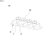
- FIG. 1 is a view showing a frictional resistance-reducing device according to some embodiments of the present disclosure, not covered by the present invention
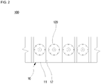
- FIG. 2 is a view of the frictional resistance-reducing device of FIG.1 viewed from above.
- a frictional resistance-reducing device 100 may reduce frictional resistance relative to a hull 10 by discharging air toward a surface of the hull 10 to form an air layer on the surface of the hull 10.
- the hull 10 includes an outer panel 11.
- the outer panel 11 includes a horizontal outer panel of a ship bottom and an inclined or vertical outer panel of a ship side.
- the outer panel 11 is an outer panel of the ship bottom, but the outer panel 11 is not limited thereto.
- an upper side of the outer panel 11 of the hull 10 represents an inner side of the outer panel 11, and a lower side of the outer panel 11 of the hull 10 represents an outer side of the outer panel 11.
- a plurality of reinforcement members 12 are separately installed on the inner side of the outer panel 11.
- the reinforcement members 12 are designed so that the hull 10 has sufficient structural strength.
- the reinforcement members 12 have a T-shaped or L-shaped cross section, but are not limited thereto.
- the frictional resistance-reducing device 100 is installed between immediately adjacent reinforcement members 12 of the plurality of reinforcement members 12 installed on the hull 10.
- FIG. 3 is a perspective view of a frictional resistance-reducing device according to a first embodiment of the present disclosure, not covered by the present invention
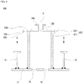
- FIG. 4 is a cross-sectional view of the frictional resistance-reducing device according to the first embodiment of the present disclosure, not covered by the present invention
- FIG. 5 is a view showing one modified example of the housing of Fig. 4 according to the present invention
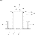
- FIG. 6 is a view showing another modified example of the housing of FIG. 4 .
- a frictional resistance-reducing device 100 includes a housing 120 and an air inlet 130.
- the housing 120 covers an air outlet 15 formed in the outer panel 11.
- the air outlet 15 covered by the housing 120 is located between the adjacent reinforcement members 12 of the reinforcement members 12 installed on the outer panel 11.
- the air outlet 15 may be formed to pass through the outer panel 11.
- the air outlet 15 discharges air to the outside of the outer panel 11.
- the air discharged through the air outlet 15 forms an air layer along an outer surface of the outer panel 11.
- the air layer may reduce frictional resistance relative to the hull 10.
- the air outlet 15 may extend in a direction perpendicular to the outer panel 11. Although not shown, the air outlet 15 may extend to be inclined relative to the outer panel 11.
- a discharge direction of the air discharged from the air outlet may be determined depending on a formation direction of the air outlet 15.
- the formation direction of the air outlet may be experimentally and experientially determined to efficiently form an air layer.
- the air outlet 15 may include a plurality of air outlets.
- the housing 120 may cover the plurality of air outlets 15.
- the housing 120 may have a hollow shape with one surface that is open.
- the housing 120 may have a circular cross section.
- the housing 120 may have a circular cylinder shape with a vertically uniform diameter.
- the housing 120 may include a large diameter part 126, a small diameter part 127, and a diameter changing part 128.
- the large diameter part 126 may have a cylinder shape with a predetermined diameter.
- the small diameter part 127 may have a cylinder shape with a diameter relatively smaller than that of the large diameter part 126.
- the diameter changing part 128 connects the large diameter part 126 with the small diameter part 127 and has a cone shape with a diameter smaller in an inward direction of the outer panel 11.
- the housing may be configured of only a large diameter part or only a cone-shaped diameter changing part. Further, the housing may have a curved-pipe shape. In addition, the housing may have a hollow form with a circular cross section and various shapes.
- the air inlet 130 is formed at one side of the housing 120.
- the air inlet 130 is formed at the other surface of the housing 120.
- the housing 120 is disposed so that the one open surface between the pair of reinforcement members 12 covers the plurality of air outlets 15.
- the housing 120 functions as a type of chamber.
- the housing 120 disposed as described above may be treated as fittings in accordance with a regulation of a ship's classification. In this case, an additional process for reinforcing a structure generated when the housing 120 is treated as a part of the hull 10 may be omitted. Therefore, costs and time for manufacturing and installing the housing 120 may be reduced.
- the housing 120 is coupled to the inner surface of the outer panel 11.
- the housing 120 may be coupled to the inner surface of the outer panel 11 through welding.
- the housing 120 may be perpendicularly coupled to the inner surface of the outer panel 11.
- the housing 120 may include a body unit 121 and a cover unit 122.
- the body unit 121 has a hollow shape with both surfaces open.
- the body unit 121 may have a circular cylinder shape.
- the body unit 121 is perpendicularly coupled to the inner surface of the outer panel 11 so that the one of the open surfaces covers the plurality of air outlets 15.
- the cover unit 122 covers the other open surface of the body unit 121.
- the cover unit 122 may be separately manufactured and coupled to the body unit 121.
- the body unit 121 may be coupled with the cover unit 122 through a flange.
- the flange 123 is formed at an end of the body unit 121 to which the cover unit 122 is coupled, and the cover unit 122 is coupled to the flange of the body unit 121 through a bolt 124 and a nut 125.
- a sealing member may be interposed between the cover unit 122 and the flange 123.
- the body unit 121 and the cover unit 122 may be coupled and welded to each other, as shown in FIG. 6 .
- the housing may have a body unit and a cover unit integrally coupled with each other.
- the air inlet 130 may be formed at the other surface of the housing 120 (or the cover unit 122). In this case, the air inlet 130 may be formed in the center of the other surface of the housing 120, but the air inlet 130 is not limited thereto.
- the air inlet 130 may be formed at one side of the other surface of the housing 120.
- the air inlet 130 may be formed in a side wall (that is, the body unit 121) of the housing 120.
- there may be two or more air inlets 130.
- at least two air inlets 130 may be formed in the other surface of the housing 120, may be formed in both side walls thereof, and may be formed in the other surface and the side wall.
- connection unit 140 connected with the air inlet 130 may be formed on the housing 120.
- the connection unit 140 may have a flange form.
- the connection unit 140 is connected with an air supply line (not shown) supplying air generated by an air supply source (not shown).
- a blocking valve (not shown) may be interposed between the connection unit 140 and the air supply line (not shown) to prevent water outside the hull from being introduced into the hull.
- the air inlet may be directly connected to the air supply line without the connection unit.
- the blocking valve may be installed in the air supply line to prevent the water outside the hull from being introduced into the hull.
- the air inlet 130 provides a path through which air supplied through the air supply line (not shown) is introduced into the housing 120.
- the air introduced into the housing 120 may be discharged to the outside of the outer panel 11 through the plurality of air outlets 15.
- the cover unit may be the blocking valve. That is, the blocking valve may be substitute for the cover unit.
- the blocking valve may be installed to cover the other surface of the body unit.
- the blocking valve may be coupled to the other surface of the body unit via a flange.
- the blocking valve is connected to the air supply line.
- the blocking valve allows air to flow into the housing when the blocking valve is opened.
- the blocking valve prevents the water outside the hull from being introduced into the hull when the blocking valve is closed. For example, when operation of the frictional resistance-reducing device according to the embodiment of the present invention is stopped, the blocking valve is closed to block the water outside the hull from flowing into the hull backward.
- FIG. 7 is a cross-sectional view taken along line A-A of FIG. 4 .
- the plurality of air outlets 15 that the housing 120 covers are formed in the outer panel 11 between the pair of adjacent reinforcement members 12.
- FIG. 7 shows the housing 120 covering the four air outlets 15, the example is illustrative in purpose only.
- the number of air outlets 15 may be determined in consideration of a size of the hull 10 or an effect of discharging air.
- a virtual line C passing through the center of the air inlet 130 may be formed to be perpendicular to the outer panel 11.
- FIG. 4 shows that the virtual line C passes through the air inlet 130, but the virtual line C is not limited thereto.
- the air inlet 130 may be disposed at a side wall of the housing 120, and there may be two or more air inlets 130.
- the plurality of air outlets 15 may be disposed in a circumferential direction with respect to the virtual line C at regular intervals.
- centers of the air outlets 15 are disposed on a virtual circle R with a predetermined radius with respect to the virtual line C and have regular intervals.
- the plurality of air outlets 15 have a structure symmetrical with respect to the virtual line C, and air introduced through the air inlet 130 and moving along the virtual line C may be uniformly discharged toward the outer panel 11 through the plurality of air outlets 15 with the symmetrical structure.
- the frictional resistance-reducing device 100 may include a plurality of housings 120.
- the plurality of air outlets are formed in the outer panel 11 to pass therethrough.
- the plurality of air outlets formed in the outer panel 11 may be distributed in at least one direction of a longitudinal direction of the reinforcement member 12 and a direction perpendicular to the longitudinal direction of the reinforcement member 12.
- the plurality of housings 120 may be separately distributed in at least one direction of the longitudinal direction of the reinforcement member 12 and the direction perpendicular to the longitudinal direction of the reinforcement member 12 to cover at least one of the plurality of air outlets formed on the outer panel 11.
- the plurality of housings 120 are disposed in the direction perpendicular to the longitudinal direction of the reinforcement members 12 and, as shown in FIG. 2 , each of the housings 120 is disposed between a pair of adjacent reinforcement members among the reinforcement members 12, or, although not shown, a plurality of housings 120 may be disposed between a pair of adjacent reinforcement members.
- FIG. 8 is a view for describing a frictional resistance-reducing device according to a second embodiment of the present disclosure, not covered by the present invention, and for convenience of description, the following description will focus on differences with descriptions based on FIGS. 1 to 7 .
- a housing 220 may be provided in a hollow shape with a regular polygon-shaped cross section.
- the cross section of the housing 220 may include a regular polygon, as shown in FIG. 8 , but this shape is illustrative in purpose only, and the housing 220 may have various regular polygon-shaped cross sections.
- the housing 220 has one surface that is open and has an air inlet (not shown) formed in the center of the other surface thereof.
- the housing 220 may be disposed so that the one open surface between a pair of reinforcement members 12 covers the plurality of air outlets 15.
- the housing 220 may be perpendicularly coupled to an inner surface of the outer panel 11.
- the number of the plurality of air outlets 15 that the housing 220 covers may be provided to be the same as the number of sides of the regular polygon-shaped cross section of the housing 220.
- the housing 200 has a square-shaped cross section, as shown in FIG. 8 , the four air outlets 15 that the housing 220 covers may be provided.
- the plurality of air outlets 15 are disposed to be perpendicular to the outer panel 11 at regular intervals about a virtual line C in a circumferential direction.
- air introduced into the housing 220 through an air inlet may be uniformly discharged toward the outer panel 11 through the air outlets 15.
- the housing may include a large area part, a small area part, and an area changing part.
- the large area part may have a predetermined area and may be disposed to cover the air outlet 15, and the small area part may have a relatively smaller area than the large area part.
- the area changing part may connect the large area part with the small area part and may be provided to have an area smaller toward an inward direction of the outer panel.
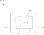
- FIG. 9 is a view for describing a frictional resistance-reducing device according to a third embodiment of the present disclosure, not covered by the present invention. For convenience of description, the following description will focus on differences with descriptions based on FIGS. 1 to 7 .
- a housing 320 may have a rectangular cross section and a hollow shape.
- the housing 320 has one surface that is open and an air inlet (not shown) formed in the center of the other surface thereof.
- the number of the plurality of air outlets 15 that the housing 320 covers may be four, which is the same number of sides of the rectangular cross section of the housing 320. In this case, the plurality of air outlets 15 may be disposed on an edge of the housing 320.
- the plurality of air outlets 15 are positioned to be perpendicular to the outer panel 11 at the same distance from a virtual line C.
- the plurality of air outlets 15 may have a structure symmetrical with respect to the center of the virtual line C.
- the housing may include a large area part, a small area part, and an area changing part.
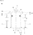
- FIG. 10 is a cross-sectional view of a frictional resistance-reducing device according to a fourth embodiment of the present disclosure, not covered by the present invention
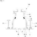
- FIG. 11 is a view showing one modified example of the housing of Fig. 10 according to an embodiment of the present invention
- FIG. 12 is a view showing another modified example of the housing of FIG. 10
- FIG. 13 is a cross-sectional view taken along line B-B of FIG. 10 .
- a frictional resistance-reducing device 100 includes a housing 120 and an air inlet 130.
- the housing 120 covers the air outlet 15 formed on the outer panel 11.
- the air outlet 15 that the housing 120 covers is located between a pair adjacent of reinforcement members 12 among the reinforcement members 12 installed on the outer panel 11.
- the air outlet 15 may be formed to pass through the outer panel 11.
- Air is discharged to the outside of the outer panel 11 through the air outlet 15.
- the air discharged through the air outlet 15 forms an air layer along an outer surface of the outer panel 11.
- the air layer may reduce frictional resistance relative to the hull 10.
- An antifouling device may be installed in the housing 120.
- the antifouling device may include an anode 20.
- the housing 120 may have a hollow shape with one surface that is open.
- the housing 120 may have a circular cross section.
- the housing 120 may have a circular cross section.
- the housing 120 may have a circular cylinder shape with a predetermined diameter in a vertical direction.
- the housing 120 may include a large diameter part 126, a small diameter part 127, and a diameter changing part 128.
- the housing 120 may include an air inlet 130.
- the air inlet 130 may be formed on the other surface facing the one open surface of the housing 120.
- the air inlet 130 may be formed in a lateral surface that does not face the one open surface of the housing 120.
- the housing 120 is coupled to the inner surface of the outer panel 11.
- the housing 120 may include a body unit 121 and a cover unit 122.
- the body unit 121 has a hollow shape with both surfaces open.
- the body unit 121 is perpendicularly coupled to the inner surface of the outer panel 11 so that the one of the open surfaces covers the plurality of air outlets 15.
- the cover unit 122 covers the other open surface of the body unit 121.
- the cover unit 122 may be separately manufactured and may be coupled to the body unit 121.
- the body unit 121 and the cover unit 122 may be coupled through a flange.
- the body unit 121 and the cover unit 122 may be coupled through welding, as shown in FIG. 12 .
- the housing may include a body unit and an cover unit that are integrally formed.
- a specific area 30 of the outer panel 11 facing the one open surface of the housing 120 may include a base unit 31 and a door unit 32.
- a through hole 40 connected with the inside of the housing 120 may be formed in the base unit 31.
- a worker may perform work on the inside of the housing 120 through the through hole 40 formed in the base unit 31.
- the worker may use the through hole 40 formed in the base unit 31 to replace the anode 20 in the housing 120.
- the worker may easily perform maintenance and repair work on the inside of the housing 120 through the through hole 40.
- the through hole 40 may have a circular shape, as shown in FIG. 13 , but is not limited thereto.
- the door unit 32 opens or closes the through hole 40.
- the air outlets 15 may be formed on the door unit 32.
- the door unit 32 may be coupled to the base unit 31.
- the door unit 32 may be coupled to the base unit 31 through a bolt, as shown in FIG. 13 .
- a support unit 50 extending in a direction toward the center of the through hole 40 may be formed on the base unit 31.
- the door unit 32 may be coupled to the support unit 50 via a bolt.
- An insertion groove (not shown) into which a head of the bolt is inserted so that the bolt is not exposed to the outside may be formed in the door unit 32.
- a plurality of support units 50 may be provided, as shown in FIG. 13 .
- the plurality of support units 50 may be formed in a radial direction relative to the through hole 40.
- the support unit may have a ring shape as a single member.
- the support unit 50 may be disposed in the housing 120, as shown in FIG. 13 . In this case, a portion exposed to the outside of the outer panel 11 may be minimized.
- FIG. 14 is a view for describing a frictional resistance-reducing device according to a fifth embodiment of the present disclosure, not covered by the present invention. For convenience of description, the following description will focus on differences with descriptions based on FIGS. 10 to 13 .
- a door unit 32 may be hinge-coupled to the base unit 31. That is, the door unit 32 may be hinge-coupled to the base unit 31 to rotate in the housing 120.
- a hinge axis X may be located in the housing 120.
- the hinge axis X may be located in the housing 120. In this case, a portion exposed to the outside of the outer panel 11 may be minimized.
- a boundary part of the door unit 32 and a boundary part of the through hole 40 may have a tapered shape to prevent the door unit 32 from rotating outside the housing 120.
- the door unit 32 hinge-coupled to the base unit 31 When the door unit 32 hinge-coupled to the base unit 31 is closed, the door unit 32 may be coupled to the base unit 31 in a bolt-coupling method, as shown in FIG. 13 .
- FIG. 15 is a view for describing a frictional resistance-reducing device according to a sixth embodiment of the present disclosure, not covered by the present invention
- FIG. 16 is a view for describing a frictional resistance-reducing device according to a seventh embodiment of the present disclosure, not covered by the present invention.
- FIGS. 10 to 13 For convenience of description, the following description will focus on differences with descriptions based on FIGS. 10 to 13 .
- the air outlet 15 may be formed on the base unit 31, as shown in FIG. 15 .
- the air outlet 15 may be formed in both the base unit 31 and the door unit 32. That is, the air outlet 15 may be formed at a boundary between the base unit 31 and the door unit 32.
Landscapes
- Chemical & Material Sciences (AREA)
- Engineering & Computer Science (AREA)
- Combustion & Propulsion (AREA)
- Mechanical Engineering (AREA)
- Ocean & Marine Engineering (AREA)
- Physics & Mathematics (AREA)
- Fluid Mechanics (AREA)
- Pressure Vessels And Lids Thereof (AREA)
- Patch Boards (AREA)
- Casings For Electric Apparatus (AREA)
- Air-Flow Control Members (AREA)
Description
- The present invention relates to a frictional resistance-reducing device and a ship including the same.
- Frictional resistance is generated at a hull of a sailing ship due to water. The frictional resistance is proportional to a submerged area of a hull submerged under water. A ship, especially a large ship, has a hull with a flat bottom surface. The bottom surface is a large portion of a surface area of the hull submerged under water.
- An air layer may be formed at the bottom surface by air being discharged toward the bottom surface in order to reduce frictional resistance applied to the bottom surface as is known e.g. from
EP 0 903 287 A2 ,JP HI 1 227675 A WO 213/002182 A1 -
EP0903287 A1 describes a ship with reduced skin friction, which achieves its friction reducing effects by blowing out gas as micro-bubbles from gas jet outlets into the water at the interface with the submerged surface of the ship's hull. The ship has laminar protrusion sections on both lateral surfaces of its bulbous bow. The laminar protrusion sections are integrally formed with and protrude from the outer plate of the ship. At the apex region of the laminar protrusion sections a plurality of gas jet outlets are provided which are connected to a gas supply pipe. -
JP H11 227675 A -
WO 2013/002182 A1 describes an air lubrication system of a ship, which is provided with an air supply device, an air blowing unit, and an air cooler. The air blowing unit blows air supplied from the air supply device into the water. The air cooler uses sea water to cool said air. -
JP 2015 081043 A -
US 2014 331912 A1 describes an apparatus for friction reduction and biofouling prevention, which consists of an anodic electro-catalytic layer and a cathodic electro-catalytic layer installed on the submerged surface of a carrier. There is an insulating filling between the anodic layer and the cathodic layer. The layered coatings are applied with the use of electric arc spraying technique. A first DC power supply unit is connected to the anodic layer and the cathodic layer. The anodic layer, the cathodic layer, the DC power supply unit, and water together form the conducting path for water electro-catalysis. Hydrogen and oxygen gases are produced to form a thin gas film on the submerged surface to reduce friction and prevent biofouling on the carrier. -
US 2006/231004 A1 describes an apparatus and method for reducing surface friction drag on the hull of a surface vessel by entraining air into water flowing in the boundary layer flow along the hull. A hemispherical protrusion creates flow separation by diverting a portion of the water flow away from the surface of the hull, which results in a reduced pressure region downstream from the protrusion. A vent located on the protrusion allow air to flow into the reduced pressure region. The air in the reduced pressure region is entrained into the water due to turbulent mixing from vortices shed on to the rear of the protrusion. -
US 2011/259440 A1 describes A inject gas control device that performs, for example, control reflecting variation in vessel velocity over time without adversely affecting the main engine. That is, it is prevented that gas is drawn too much and thereby a gas supply or charged air rate becomes insufficient, efficiency of the main engine is decreased and exhaust gas is deteriorated, and analogous events occur because the gas supply or charged air rate is too much instead. - A hull has a reinforcement member installed at a bottom surface thereof in a longitudinal direction or a transverse direction to have sufficient structural strength. However, a chamber installed at the bottom surface may have a relatively large size. Therefore, while a large chamber is installed at the bottom surface, the reinforcement member should be removed or changed. Therefore, it is hard to maintain structural strength of the hull according to a design.
- The present invention is directed to providing a frictional resistance-reducing device installed on a bottom surface of a hull while maintaining structural strength of a hull.
- The present invention is directed to providing a ship in which the frictional resistance-reducing device is installed.
- Objects of the present invention are not limited to the above-described objects and other objects that have not been described should be understood by those skilled in the art from the following description.
- One aspect of the present invention provides a ship according to claim 4.
- The air outlet may include a plurality of air outlets, the air inlet may be formed in the other surface or a side surface of the housing, and the plurality of air outlets may be disposed in the outer panel at regular intervals with respect to a virtual line in a circumferential direction.
- The housing may include a body unit having a hollow shape with both side surfaces open, and one of the surfaces thereof perpendicularly coupled to the inner surface of the outer panel, and a cover unit having an air inlet formed in the center thereof and configured to cover the other surface of the body unit.
- The body unit and the cover unit may be coupled to each other through a flange or welding.
- The cover unit may be a blocking valve configured to prevent water outside a hull from being introduced into the hull.
- The body unit may include a large diameter part having a cylinder shape, a small diameter part having a cylinder shape with a diameter relatively smaller than that of the large diameter, and a diameter changing part configured to connect the large diameter part with the small diameter part.
- The housing may have a regular polygon-shaped cross section, and the number of the plurality of air outlets may be provided to be the same as that of sides of the regular polygon-shaped cross section of the housing.
- The housing may have a rectangular cross section and be perpendicularly coupled to the inner side surface of the outer panel, the air inlet may be formed in the center of the other surface of the housing, and a plurality of air outlets may be disposed at an edge of the housing and positioned to be perpendicular to the outer panel at a regular distance from a virtual line.
- The housing may include a plurality of housings, and the plurality of housings may be disposed in a longitudinal direction of the reinforcement member or a direction perpendicular to the longitudinal direction of the reinforcement member.
- A specific area of the outer panel facing the one open surface of the housing may include a base unit having a through hole connected with an inside of the housing, and a door unit coupled to the base unit to open and close the through hole.
- The air outlet may be formed in at least one location among the door unit, the base unit, and a boundary between the base unit and the door unit.
- The door unit may be coupled with the base unit through a bolt.
- The door unit may be hinge-coupled to the base unit to rotate toward the inside of the housing.
- A boundary part of the door unit and a boundary part of the through hole may have a tapered shape to prevent the door unit from rotating outside the housing.
- Another aspect of the present invention provides a frictional resistance-reducing according to
claim 1. - A specific area of the outer panel facing the one open surface of the housing may include a base unit having a through hole connected with an inside of the housing, and a door unit coupled to the base unit to open or close the through hole.
- The housing may include an antifouling device installed therein.
- Details of other embodiments are included in the detailed description and the accompanying drawings.
- A ship according to some embodiments of the present invention can prevent structural strength thereof from being degraded by having a housing installed between a pair of immediately adjacent reinforcement members. Therefore, an additional process for reinforcing a structure of a hull can be omitted, and thus costs and time for manufacturing and installation can be reduced.
- A ship according to some embodiments of the present invention includes a through hole formed in a predetermined area of an outer panel facing one open surface of a housing, and the through hole can be opened or closed via a door unit. Thus, a worker can easily perform maintenance work on the inside of the housing.
-
-
FIG. 1 is a view showing a frictional resistance-reducing device according to some embodiments of the present disclosure, not covered by the present invention. -
FIG. 2 is a view of the frictional resistance-reducing device ofFIG.1 viewed from above. -
FIG. 3 is a perspective view of a frictional resistance-reducing device according to a first embodiment of the present disclosure, not covered by the present invention. -
FIG. 4 is a cross-sectional view of the frictional resistance-reducing device according to the first embodiment of the present disclosure, not covered by the present invention. -
FIG. 5 is a view showing one modified example of the housing ofFig. 4 according to the present invention. -
FIG. 6 is a view showing another modified example of the housing ofFIG. 4 . -
FIG. 7 is a cross-sectional view taken along line A-A ofFIG. 4 . -
FIG. 8 is a view for describing a frictional resistance-reducing device according to a second embodiment of the present disclosure, not covered by the present invention. -
FIG. 9 is a view for describing a frictional resistance-reducing device according to a third embodiment of the present disclosure, not covered by the present invention. -
FIG. 10 is a cross-sectional view of a frictional resistance-reducing device according to a fourth embodiment of the present disclosure, not covered by the present invention. -
FIG. 11 is a view showing one modified example of the housing ofFig. 10 according to an embodiment of the present invention . -
FIG. 12 is a view showing another modified example of the housing ofFIG. 10 . -
FIG. 13 is a cross-sectional view taken along line B-B ofFIG. 10 . -
FIG. 14 is a view for describing a frictional resistance-reducing device according to a fifth embodiment of the present disclosure, not covered by the present invention. -
FIG. 15 is a view for describing a frictional resistance-reducing device according to a sixth embodiment of the present disclosure, not covered by the present invention. -
FIG. 16 is a view for describing a frictional resistance-reducing device according to a seventh embodiment of the present disclosure, not covered by the present invention. - Exemplary embodiments of the present invention will be illustrated in the drawings and described in detail in the written description, but the embodiments may be changed and have many alternative forms. However, the present invention is not limited to particular modes of practice, and it should be appreciated that all changes, equivalents, and substitutes not departing from the technical scope of embodiments are encompassed in embodiments. In the description of the embodiments, certain detailed descriptions of a related art will be omitted when it is deemed that they unnecessarily obscure the essence of the inventive concept.
- Hereinafter, embodiments of the present invention will be described in detail with reference to the accompanying drawings. When describing the invention with reference to the accompanying drawings, the same or similar elements are designated with the same numeral references, and redundant descriptions thereof will be omitted.
-
FIG. 1 is a view showing a frictional resistance-reducing device according to some embodiments of the present disclosure, not covered by the present invention, andFIG. 2 is a view of the frictional resistance-reducing device ofFIG.1 viewed from above. - Referring to
FIGS. 1 and2 , a frictional resistance-reducingdevice 100 according to some embodiments of the present invention may reduce frictional resistance relative to ahull 10 by discharging air toward a surface of thehull 10 to form an air layer on the surface of thehull 10. - The
hull 10 includes anouter panel 11. Theouter panel 11 includes a horizontal outer panel of a ship bottom and an inclined or vertical outer panel of a ship side. Hereinafter, in the embodiment, it is assumed that theouter panel 11 is an outer panel of the ship bottom, but theouter panel 11 is not limited thereto. For reference, inFIG. 1 , an upper side of theouter panel 11 of thehull 10 represents an inner side of theouter panel 11, and a lower side of theouter panel 11 of thehull 10 represents an outer side of theouter panel 11. - A plurality of
reinforcement members 12 are separately installed on the inner side of theouter panel 11. Thereinforcement members 12 are designed so that thehull 10 has sufficient structural strength. Thereinforcement members 12 have a T-shaped or L-shaped cross section, but are not limited thereto. - The frictional resistance-reducing
device 100 according to the embodiments of the present invention is installed between immediatelyadjacent reinforcement members 12 of the plurality ofreinforcement members 12 installed on thehull 10. -
FIG. 3 is a perspective view of a frictional resistance-reducing device according to a first embodiment of the present disclosure, not covered by the present invention,FIG. 4 is a cross-sectional view of the frictional resistance-reducing device according to the first embodiment of the present disclosure, not covered by the present invention,FIG. 5 is a view showing one modified example of the housing ofFig. 4 according to the present invention, andFIG. 6 is a view showing another modified example of the housing ofFIG. 4 . - First, referring to
FIGS. 3 and4 , a frictional resistance-reducingdevice 100 according to the first embodiment of the present disclosure, not covered by the present invention, includes ahousing 120 and anair inlet 130. - The
housing 120 covers anair outlet 15 formed in theouter panel 11. Theair outlet 15 covered by thehousing 120 is located between theadjacent reinforcement members 12 of thereinforcement members 12 installed on theouter panel 11. Theair outlet 15 may be formed to pass through theouter panel 11. - The
air outlet 15 discharges air to the outside of theouter panel 11. The air discharged through theair outlet 15 forms an air layer along an outer surface of theouter panel 11. The air layer may reduce frictional resistance relative to thehull 10. - The
air outlet 15 may extend in a direction perpendicular to theouter panel 11. Although not shown, theair outlet 15 may extend to be inclined relative to theouter panel 11. - A discharge direction of the air discharged from the air outlet may be determined depending on a formation direction of the
air outlet 15. For example, the formation direction of the air outlet may be experimentally and experientially determined to efficiently form an air layer. - The
air outlet 15 may include a plurality of air outlets. In this case, thehousing 120 may cover the plurality ofair outlets 15. - The
housing 120 may have a hollow shape with one surface that is open. For example, thehousing 120 may have a circular cross section. - For example, as shown in
FIG. 4 , thehousing 120 may have a circular cylinder shape with a vertically uniform diameter. - According to the present invention, as shown in
FIG. 5 , thehousing 120 may include alarge diameter part 126, asmall diameter part 127, and adiameter changing part 128. Thelarge diameter part 126 may have a cylinder shape with a predetermined diameter. Thesmall diameter part 127 may have a cylinder shape with a diameter relatively smaller than that of thelarge diameter part 126. Thediameter changing part 128 connects thelarge diameter part 126 with thesmall diameter part 127 and has a cone shape with a diameter smaller in an inward direction of theouter panel 11. - Although not shown, the housing may be configured of only a large diameter part or only a cone-shaped diameter changing part. Further, the housing may have a curved-pipe shape. In addition, the housing may have a hollow form with a circular cross section and various shapes.
- Referring to
FIGS. 3 and4 , theair inlet 130 is formed at one side of thehousing 120. For example, theair inlet 130 is formed at the other surface of thehousing 120. - The
housing 120 is disposed so that the one open surface between the pair ofreinforcement members 12 covers the plurality ofair outlets 15. Thehousing 120 functions as a type of chamber. - When the
housing 120 functioning as a chamber is disposed between the pair ofreinforcement members 12, it is not necessary for the reinforcement members installed on theouter panel 11 to be removed or changed, and thus structural strength of thehull 10 for a design is not degraded. - The
housing 120 disposed as described above may be treated as fittings in accordance with a regulation of a ship's classification. In this case, an additional process for reinforcing a structure generated when thehousing 120 is treated as a part of thehull 10 may be omitted. Therefore, costs and time for manufacturing and installing thehousing 120 may be reduced. - The
housing 120 is coupled to the inner surface of theouter panel 11. In this case, thehousing 120 may be coupled to the inner surface of theouter panel 11 through welding. Thehousing 120 may be perpendicularly coupled to the inner surface of theouter panel 11. - Meanwhile, the
housing 120 may include abody unit 121 and acover unit 122. - The
body unit 121 has a hollow shape with both surfaces open. For example, as shown inFIG. 4 , thebody unit 121 may have a circular cylinder shape. - The
body unit 121 is perpendicularly coupled to the inner surface of theouter panel 11 so that the one of the open surfaces covers the plurality ofair outlets 15. Thecover unit 122 covers the other open surface of thebody unit 121. - The
cover unit 122 may be separately manufactured and coupled to thebody unit 121. - For example, the
body unit 121 may be coupled with thecover unit 122 through a flange. In this case, theflange 123 is formed at an end of thebody unit 121 to which thecover unit 122 is coupled, and thecover unit 122 is coupled to the flange of thebody unit 121 through abolt 124 and anut 125. In this case, although not shown, a sealing member may be interposed between thecover unit 122 and theflange 123. - Alternatively, the
body unit 121 and thecover unit 122 may be coupled and welded to each other, as shown inFIG. 6 . - Meanwhile, although not shown, the housing may have a body unit and a cover unit integrally coupled with each other.
- Referring to
FIG. 4 , theair inlet 130 may be formed at the other surface of the housing 120 (or the cover unit 122). In this case, theair inlet 130 may be formed in the center of the other surface of thehousing 120, but theair inlet 130 is not limited thereto. - For example, the
air inlet 130 may be formed at one side of the other surface of thehousing 120. Theair inlet 130 may be formed in a side wall (that is, the body unit 121) of thehousing 120. Further, there may be two ormore air inlets 130. For example, at least twoair inlets 130 may be formed in the other surface of thehousing 120, may be formed in both side walls thereof, and may be formed in the other surface and the side wall. - In this case, a
connection unit 140 connected with theair inlet 130 may be formed on thehousing 120. Theconnection unit 140 may have a flange form. Theconnection unit 140 is connected with an air supply line (not shown) supplying air generated by an air supply source (not shown). A blocking valve (not shown) may be interposed between theconnection unit 140 and the air supply line (not shown) to prevent water outside the hull from being introduced into the hull. - Alternatively, although not shown, the air inlet may be directly connected to the air supply line without the connection unit. In this case, the blocking valve may be installed in the air supply line to prevent the water outside the hull from being introduced into the hull.
- The
air inlet 130 provides a path through which air supplied through the air supply line (not shown) is introduced into thehousing 120. The air introduced into thehousing 120 may be discharged to the outside of theouter panel 11 through the plurality ofair outlets 15. - Meanwhile, although not shown, the cover unit may be the blocking valve. That is, the blocking valve may be substitute for the cover unit. In this case, the blocking valve may be installed to cover the other surface of the body unit. In this case, the blocking valve may be coupled to the other surface of the body unit via a flange.
- The blocking valve is connected to the air supply line. The blocking valve allows air to flow into the housing when the blocking valve is opened.
- The blocking valve prevents the water outside the hull from being introduced into the hull when the blocking valve is closed. For example, when operation of the frictional resistance-reducing device according to the embodiment of the present invention is stopped, the blocking valve is closed to block the water outside the hull from flowing into the hull backward.
-
FIG. 7 is a cross-sectional view taken along line A-A ofFIG. 4 . - Referring to
FIG. 7 , the plurality ofair outlets 15 that thehousing 120 covers are formed in theouter panel 11 between the pair ofadjacent reinforcement members 12. For reference, althoughFIG. 7 shows thehousing 120 covering the fourair outlets 15, the example is illustrative in purpose only. The number ofair outlets 15 may be determined in consideration of a size of thehull 10 or an effect of discharging air. - When the
housing 120 is perpendicularly coupled to theouter panel 11 and theair inlet 130 is formed in the center of the other surface of thehousing 120, a virtual line C (seeFIGS. 4 and7 ) passing through the center of theair inlet 130 may be formed to be perpendicular to theouter panel 11. - Further,
FIG. 4 shows that the virtual line C passes through theair inlet 130, but the virtual line C is not limited thereto. As described above, theair inlet 130 may be disposed at a side wall of thehousing 120, and there may be two ormore air inlets 130. - The plurality of
air outlets 15 may be disposed in a circumferential direction with respect to the virtual line C at regular intervals. - In other words, as shown in
FIG. 7 , centers of theair outlets 15 are disposed on a virtual circle R with a predetermined radius with respect to the virtual line C and have regular intervals. - In this case, the plurality of
air outlets 15 have a structure symmetrical with respect to the virtual line C, and air introduced through theair inlet 130 and moving along the virtual line C may be uniformly discharged toward theouter panel 11 through the plurality ofair outlets 15 with the symmetrical structure. - The air uniformly discharged through the plurality of air outlets forms an optimal air layer on the surface of the
hull 10 or is maintained to reduce the frictional resistance relative to thehull 10. Meanwhile, referring toFIGS. 1 and2 , the frictional resistance-reducingdevice 100 may include a plurality ofhousings 120. In this regard, the plurality of air outlets (not shown) are formed in theouter panel 11 to pass therethrough. The plurality of air outlets formed in theouter panel 11 may be distributed in at least one direction of a longitudinal direction of thereinforcement member 12 and a direction perpendicular to the longitudinal direction of thereinforcement member 12. - In this case, the plurality of
housings 120 may be separately distributed in at least one direction of the longitudinal direction of thereinforcement member 12 and the direction perpendicular to the longitudinal direction of thereinforcement member 12 to cover at least one of the plurality of air outlets formed on theouter panel 11. - The plurality of
housings 120 are disposed in the direction perpendicular to the longitudinal direction of thereinforcement members 12 and, as shown inFIG. 2 , each of thehousings 120 is disposed between a pair of adjacent reinforcement members among thereinforcement members 12, or, although not shown, a plurality ofhousings 120 may be disposed between a pair of adjacent reinforcement members. -
FIG. 8 is a view for describing a frictional resistance-reducing device according to a second embodiment of the present disclosure, not covered by the present invention, and for convenience of description, the following description will focus on differences with descriptions based onFIGS. 1 to 7 . - Referring to
FIG. 8 , in a frictional resistance-reducingdevice 200 according to the second embodiment of the present disclosure, not covered by the present invention, ahousing 220 may be provided in a hollow shape with a regular polygon-shaped cross section. For example, the cross section of thehousing 220 may include a regular polygon, as shown inFIG. 8 , but this shape is illustrative in purpose only, and thehousing 220 may have various regular polygon-shaped cross sections. - The
housing 220 has one surface that is open and has an air inlet (not shown) formed in the center of the other surface thereof. - The
housing 220 may be disposed so that the one open surface between a pair ofreinforcement members 12 covers the plurality ofair outlets 15. Thehousing 220 may be perpendicularly coupled to an inner surface of theouter panel 11. - In this case, the number of the plurality of
air outlets 15 that thehousing 220 covers may be provided to be the same as the number of sides of the regular polygon-shaped cross section of thehousing 220. For example, when thehousing 200 has a square-shaped cross section, as shown inFIG. 8 , the fourair outlets 15 that thehousing 220 covers may be provided. - The plurality of
air outlets 15 are disposed to be perpendicular to theouter panel 11 at regular intervals about a virtual line C in a circumferential direction. In this case, air introduced into thehousing 220 through an air inlet (not shown) may be uniformly discharged toward theouter panel 11 through theair outlets 15. - Although not shown, like the
housing 120 shown inFIG. 5 , the housing may include a large area part, a small area part, and an area changing part. In this case, the large area part may have a predetermined area and may be disposed to cover theair outlet 15, and the small area part may have a relatively smaller area than the large area part. The area changing part may connect the large area part with the small area part and may be provided to have an area smaller toward an inward direction of the outer panel. -
FIG. 9 is a view for describing a frictional resistance-reducing device according to a third embodiment of the present disclosure, not covered by the present invention. For convenience of description, the following description will focus on differences with descriptions based onFIGS. 1 to 7 . - Referring to
FIG. 9 , in a frictional resistance-reducingdevice 300 according to the third embodiment of the present disclosure, not covered by the present invention, ahousing 320 may have a rectangular cross section and a hollow shape. Thehousing 320 has one surface that is open and an air inlet (not shown) formed in the center of the other surface thereof. - The number of the plurality of
air outlets 15 that thehousing 320 covers may be four, which is the same number of sides of the rectangular cross section of thehousing 320. In this case, the plurality ofair outlets 15 may be disposed on an edge of thehousing 320. - The plurality of
air outlets 15 are positioned to be perpendicular to theouter panel 11 at the same distance from a virtual line C. In this case, the plurality ofair outlets 15 may have a structure symmetrical with respect to the center of the virtual line C. When theair outlets 15 are disposed as described above, air introduced into thehousing 320 through an air inlet (not shown) may be uniformly discharged toward theouter panel 11 through theair outlets 15. - Although not shown, like the
housing 120 shown inFIG. 5 , the housing may include a large area part, a small area part, and an area changing part. -
FIG. 10 is a cross-sectional view of a frictional resistance-reducing device according to a fourth embodiment of the present disclosure, not covered by the present invention,FIG. 11 is a view showing one modified example of the housing ofFig. 10 according to an embodiment of the present invention,FIG. 12 is a view showing another modified example of the housing ofFIG. 10 , andFIG. 13 is a cross-sectional view taken along line B-B ofFIG. 10 . For convenience of description, the following description will focus on differences with descriptions based onFIGS. 1 to 7 . - First, referring to
FIGS. 10 and13 , a frictional resistance-reducingdevice 100 according to the fourth embodiment of the present disclosure, not covered by the present invention, includes ahousing 120 and anair inlet 130. - The
housing 120 covers theair outlet 15 formed on theouter panel 11. Theair outlet 15 that thehousing 120 covers is located between a pair adjacent ofreinforcement members 12 among thereinforcement members 12 installed on theouter panel 11. Theair outlet 15 may be formed to pass through theouter panel 11. - Air is discharged to the outside of the
outer panel 11 through theair outlet 15. The air discharged through theair outlet 15 forms an air layer along an outer surface of theouter panel 11. The air layer may reduce frictional resistance relative to thehull 10. - An antifouling device may be installed in the
housing 120. For example, the antifouling device may include ananode 20. - The
housing 120 may have a hollow shape with one surface that is open. In this case, thehousing 120 may have a circular cross section. For example, as shown inFIG. 10 , thehousing 120 may have a circular cross section. For example, as shown inFIG. 10 , thehousing 120 may have a circular cylinder shape with a predetermined diameter in a vertical direction. - According to one embodiment of the present invention, as shown in
FIG. 11 , thehousing 120 may include alarge diameter part 126, asmall diameter part 127, and adiameter changing part 128. - Referring to
FIGS. 10 and13 , thehousing 120 may include anair inlet 130. For example, as shown inFIG. 10 , theair inlet 130 may be formed on the other surface facing the one open surface of thehousing 120. Although not shown, theair inlet 130 may be formed in a lateral surface that does not face the one open surface of thehousing 120. - The
housing 120 is coupled to the inner surface of theouter panel 11. - The
housing 120 may include abody unit 121 and acover unit 122. - The
body unit 121 has a hollow shape with both surfaces open. Thebody unit 121 is perpendicularly coupled to the inner surface of theouter panel 11 so that the one of the open surfaces covers the plurality ofair outlets 15. Thecover unit 122 covers the other open surface of thebody unit 121. - The
cover unit 122 may be separately manufactured and may be coupled to thebody unit 121. - For example, the
body unit 121 and thecover unit 122 may be coupled through a flange. - Alternatively, the
body unit 121 and thecover unit 122 may be coupled through welding, as shown inFIG. 12 . - Meanwhile, although not shown, the housing may include a body unit and an cover unit that are integrally formed.
- Referring to
FIGS. 10 and13 , aspecific area 30 of theouter panel 11 facing the one open surface of thehousing 120 may include abase unit 31 and adoor unit 32. - A through
hole 40 connected with the inside of thehousing 120 may be formed in thebase unit 31. A worker may perform work on the inside of thehousing 120 through the throughhole 40 formed in thebase unit 31. For example, the worker may use the throughhole 40 formed in thebase unit 31 to replace theanode 20 in thehousing 120. In addition, the worker may easily perform maintenance and repair work on the inside of thehousing 120 through the throughhole 40. - The through
hole 40 may have a circular shape, as shown inFIG. 13 , but is not limited thereto. - The
door unit 32 opens or closes the throughhole 40. Theair outlets 15 may be formed on thedoor unit 32. - The
door unit 32 may be coupled to thebase unit 31. - For example, the
door unit 32 may be coupled to thebase unit 31 through a bolt, as shown inFIG. 13 . In this case, asupport unit 50 extending in a direction toward the center of the throughhole 40 may be formed on thebase unit 31. Thedoor unit 32 may be coupled to thesupport unit 50 via a bolt. - An insertion groove (not shown) into which a head of the bolt is inserted so that the bolt is not exposed to the outside may be formed in the
door unit 32. - A plurality of
support units 50 may be provided, as shown inFIG. 13 . The plurality ofsupport units 50 may be formed in a radial direction relative to the throughhole 40. Although not shown, the support unit may have a ring shape as a single member. - The
support unit 50 may be disposed in thehousing 120, as shown inFIG. 13 . In this case, a portion exposed to the outside of theouter panel 11 may be minimized. -
FIG. 14 is a view for describing a frictional resistance-reducing device according to a fifth embodiment of the present disclosure, not covered by the present invention. For convenience of description, the following description will focus on differences with descriptions based onFIGS. 10 to 13 . - Referring to
FIG. 14 , in the frictional resistance-reducing device according to the fifth embodiment of the present disclosure, not covered by the present invention, adoor unit 32 may be hinge-coupled to thebase unit 31. That is, thedoor unit 32 may be hinge-coupled to thebase unit 31 to rotate in thehousing 120. In this case, a hinge axis X may be located in thehousing 120. The hinge axis X may be located in thehousing 120. In this case, a portion exposed to the outside of theouter panel 11 may be minimized. - Further, a boundary part of the
door unit 32 and a boundary part of the throughhole 40 may have a tapered shape to prevent thedoor unit 32 from rotating outside thehousing 120. - When the
door unit 32 hinge-coupled to thebase unit 31 is closed, thedoor unit 32 may be coupled to thebase unit 31 in a bolt-coupling method, as shown inFIG. 13 . -
FIG. 15 is a view for describing a frictional resistance-reducing device according to a sixth embodiment of the present disclosure, not covered by the present invention, andFIG. 16 is a view for describing a frictional resistance-reducing device according to a seventh embodiment of the present disclosure, not covered by the present invention. For convenience of description, the following description will focus on differences with descriptions based onFIGS. 10 to 13 . - In the frictional resistance-reducing device according to the sixth embodiment of the present disclosure, not covered by the present invention, the
air outlet 15 may be formed on thebase unit 31, as shown inFIG. 15 . - In the frictional resistance-reducing device according to the sixth embodiment of the present disclosure, not covered by the present invention, as shown in
FIG. 16 , theair outlet 15 may be formed in both thebase unit 31 and thedoor unit 32. That is, theair outlet 15 may be formed at a boundary between thebase unit 31 and thedoor unit 32. - Embodiments of the present invention have been described above, but it should be understood by those skilled in the art that various changes and modifications may be made therein by addition, substitution, or removal of components without departing from the scope of the present invention as defined by the appended claims. Such changed and modified embodiments are also included within the scope of the appended claims.
-
- 10: HULL
- 11: OUTER PANEL
- 12: REINFORCEMENT MEMBERS
- 15: AIR OUTLET
- 20: ANODE
- 30: SPECIFIC AREA
- 31: BASE UNIT
- 32: DOOR UNIT
- 40: THROUGH HOLE
- 50: SUPPORT UNIT
- 100, 200, 300: FRICTIONAL RESISTANCE-REDUCING DEVICE
- 120, 220, 320: HOUSING
- 121: BODY UNIT
- 122: COVER UNIT
- 123: FLANGE
- 123 124: BOLT
- 125: NUT
- 126: LARGE DIAMETER PART
- 127: SMALL DIAMETER PART
- 128: DIAMETER CHANGING PART
- 130: AIR INLET
- 140: CONNECTION UNIT
Claims (10)
- A frictional resistance-reducing device (100; 400) suitable to be installed on a bottom surface of a ship's hull and to form an air layer on the surface of said hull, said frictional resistance-reducing device (100, 400) comprising: a housing (120) having a hollow shape with one surface that is open; and an air inlet (130) formed at one side of the housing (120), an outer panel (11); and reinforcement members (12) reinforcing the outer panel (11), wherein the one open surface of the housing (120) is installed to face an inner surface of the outer panel (11), the reinforcement members (12) reinforcing the outer panel (11) being disposed on both sides of the housing (120), and the housing (120) covering an air outlet (15) installed in the outer panel (11), the housing (120) including a body unit (121) having a hollow shape with both side surfaces open,
wherein one of said open side surfaces is coupled to the inner surface of the outer panel (11),
the housing (120) including:a large diameter part (126) having a cylinder shape;a small diameter part (127) having a cylinder shape with a diameter relatively smaller than that of the large diameter part (126); anda diameter changing part (128) configured to connect the large diameter part (126) with the small diameter part (127), the small diameter part (127) being above the large diameter part (128) in an inward direction of the outer panel (11), anda cover unit (122) having the air inlet (130) formed in the center thereof and configured to cover the other open side surface of the body unit (121),wherein the body unit (121) is perpendicularly coupled to the inner surface of the outer panel (11),the frictional resistance-reducing device being characterized in thatthe diameter changing part (128) has a cone shape with a diameter smaller in an inward direction of the outer panel. - A frictional resistance-reducing device as claimed in claim 1, wherein, when the frictional resistance-reducing device is installed in a ship, a specific area of the outer panel (11) facing the one open surface of the housing (120) includes a base unit (31) having a through hole (40) connected with an inside of the housing (120), and a door unit (32) coupled to the base unit (31) to open or close the through hole (40).
- The frictional resistance-reducing device of claim 1, wherein the housing includes an antifouling device installed therein.
- A ship comprising:a hull (10);an outer panel (11) included in the hull (10) and including an air outlet (15):a plurality of reinforcement members (12) installed on an inner surface of the outer panel (11) to be separated from each other; anda frictional resistance-reducing device (100; 400) according to claim 1 formed between the immediately adjacent reinforcement members (12) among the plurality of reinforcement members (12) on the inner surface of the outer panel (11) to cover the air outlet (15).
- A ship as claimed in claim 4, wherein:the air outlet (15) includes a plurality of air outlets (15);the housing (120) is perpendicularly coupled to the inner surface of the outer panel (11);the air inlet (130) is formed in the other surface or a side surface of the housing (120); andthe plurality of air outlets (15) are disposed in the outer panel (11) at regular intervals with respect to a virtual line (C) in a circumferential direction.
- A ship as claimed in claim 4 , wherein the housing (120) is one of a plurality of housings (120), and the plurality of housings is disposed in a longitudinal direction of the reinforcement member (12) or a direction perpendicular to the longitudinal direction of the reinforcement member (12).
- A ship as claimed in claim 4, wherein A specific area (30) of the outer panel (11) facing one open surface of the housing (120) includes a base unit (31) having a through hole (4) connected with an inside of the housing (120), and a door unit (32) coupled to the base unit (31) to open and close the through hole (40).
- A ship as claimed in claim 7, wherein the air outlet (15) is formed in at least one location among the door unit (32), the base unit (31), and a boundary between the base unit (31) and the door unit (32).
- A ship as claimed in claim 7 , wherein the door unit (32) is hinge-coupled to the base unit (31) to rotate toward the inside of the housing (120).
- A ship as claimed in claim 9, wherein a boundary part of the door unit (32) and a boundary part of the through hole (40) have a tapered shape to prevent the door unit (32) from rotating outside the housing (120).
Applications Claiming Priority (3)
| Application Number | Priority Date | Filing Date | Title |
|---|---|---|---|
| KR1020150092110A KR20170002111A (en) | 2015-06-29 | 2015-06-29 | Apparatus for reducing frictional-resistance |
| KR1020150190952A KR101801814B1 (en) | 2015-12-31 | 2015-12-31 | Apparatus for reducing frictional-resistance |
| PCT/KR2016/000610 WO2017003058A1 (en) | 2015-06-29 | 2016-01-20 | Frictional resistance-reducing device and ship including same |
Publications (3)
| Publication Number | Publication Date |
|---|---|
| EP3315396A1 EP3315396A1 (en) | 2018-05-02 |
| EP3315396A4 EP3315396A4 (en) | 2019-01-23 |
| EP3315396B1 true EP3315396B1 (en) | 2021-06-23 |
Family
ID=57608472
Family Applications (1)
| Application Number | Title | Priority Date | Filing Date |
|---|---|---|---|
| EP16818091.7A Active EP3315396B1 (en) | 2015-06-29 | 2016-01-20 | Frictional resistance-reducing device and ship including same |
Country Status (6)
| Country | Link |
|---|---|
| US (1) | US10266230B2 (en) |
| EP (1) | EP3315396B1 (en) |
| JP (1) | JP6573684B2 (en) |
| CN (1) | CN108064208B (en) |
| SG (1) | SG11201710703RA (en) |
| WO (1) | WO2017003058A1 (en) |
Families Citing this family (6)
| Publication number | Priority date | Publication date | Assignee | Title |
|---|---|---|---|---|
| US10266230B2 (en) | 2015-06-29 | 2019-04-23 | Samsung Heavy Industries Co., Ltd. | Frictional resistance-reducing device and ship including same |
| CN108177724A (en) * | 2018-01-12 | 2018-06-19 | 中船重工船舶设计研究中心有限公司 | A kind of voltage stabilizing cavity configuration and installation method for resistance reduction by air cavity technology |
| USD919546S1 (en) * | 2020-01-10 | 2021-05-18 | Thomas Sandstrom | Sea chest for marine vessels |
| SG10202103943RA (en) * | 2020-04-20 | 2021-11-29 | Daewoo Shipbuilding & Marine | Air lubrication system of a ship |
| CN115556867B (en) * | 2022-10-17 | 2024-11-15 | 中国船舶重工集团公司七五0试验场 | Simple disassembly hole cover for underwater vehicle |
| CN119689837B (en) * | 2024-12-12 | 2026-04-28 | 上海交通大学 | A method for designing swarms of unmanned surface vessels capable of aggregation and dispersal. |
Citations (2)
| Publication number | Priority date | Publication date | Assignee | Title |
|---|---|---|---|---|
| US20060231004A1 (en) * | 2005-04-15 | 2006-10-19 | North Shore Partners | Apparatus and method for reducing fluid drag on a submerged surface |
| US20110259440A1 (en) * | 2008-04-01 | 2011-10-27 | Hideki Kawashima | Frictional resistance reduction device for ship |
Family Cites Families (27)
| Publication number | Priority date | Publication date | Assignee | Title |
|---|---|---|---|---|
| US4214332A (en) * | 1978-04-24 | 1980-07-29 | Ares, Inc. | Method of constructing welded metal skin boat hulls and hulls made thereby |
| KR100188464B1 (en) * | 1993-05-11 | 1999-06-01 | 다께이 도시후미 | Method and device of reducing friction on a navigating vehicle |
| WO1997020728A1 (en) * | 1995-12-04 | 1997-06-12 | Ishikawajima-Harima Heavy Industries Co., Ltd. | Method of reducing friction resistance of hull, ship whose friction resistance is reduced by the method, and method of analyzing jetted bubbles on ship |
| JPH1035578A (en) * | 1996-07-19 | 1998-02-10 | Ishikawajima Harima Heavy Ind Co Ltd | Ship friction reduction device |
| GB2326300B (en) | 1997-06-10 | 2001-11-21 | Sony Uk Ltd | Concealing errors |
| JPH11291974A (en) * | 1998-04-06 | 1999-10-26 | Ishikawajima Harima Heavy Ind Co Ltd | Air blower for ship with reduced frictional resistance |
| CA2244615A1 (en) * | 1997-08-22 | 1999-02-22 | Ishikawajima-Harima Heavy Industries Co., Ltd. | Friction-reducing ship with compressed air generation apparatus, friction reduction apparatus and gas jetting device |
| JPH11227675A (en) * | 1998-02-13 | 1999-08-24 | Ishikawajima Harima Heavy Ind Co Ltd | Air blower for ship with reduced frictional resistance |
| US6145459A (en) * | 1997-12-19 | 2000-11-14 | Ishikawajima-Harima Heavy Industries Co., Ltd. | Friction-reducing ship and method for reducing skin friction |
| JP2000128063A (en) * | 1998-10-22 | 2000-05-09 | Ishikawajima Harima Heavy Ind Co Ltd | Ship friction reduction device |
| JP2001055189A (en) * | 1999-06-08 | 2001-02-27 | Ishikawajima Harima Heavy Ind Co Ltd | Method of reducing frictional resistance of hull and ship with reduced frictional resistance |
| US6789491B2 (en) * | 2000-04-03 | 2004-09-14 | Ishikawajima-Harima Heavy Industries Co., Ltd. | Friction reducing ship and method for reducing frictional resistance |
| WO2004012987A2 (en) * | 2002-04-26 | 2004-02-12 | Board Of Regents | Methods for reducing the viscous drag on a surface and drag reducing device |
| FR2882542B1 (en) * | 2005-02-25 | 2007-04-20 | Claude Carbonel | SELF-STABILIZING DEVICE FOR BOAT SHELL |
| AR055208A1 (en) * | 2006-06-30 | 2007-08-15 | Schoo Raul Alberto Iglesias | PNEUMATIC ENVIRONMENT FACILITATOR FOR THE SURFACE SLIDING OF BOATS IN THE MASS OF WATER |
| JP5082093B2 (en) * | 2006-11-13 | 2012-11-28 | 独立行政法人海上技術安全研究所 | Friction resistance reduction method for hull |
| JP4953296B2 (en) | 2006-12-08 | 2012-06-13 | 独立行政法人海上技術安全研究所 | Hull frictional resistance reduction device |
| US8677918B2 (en) * | 2008-01-10 | 2014-03-25 | Lawrence Harbin | Marine vessel having reduced skin friction drag |
| US8196536B1 (en) * | 2008-01-10 | 2012-06-12 | Lawrence Harbin | Apparatus to reduce skin friction drag on a marine vessel |
| JP5022346B2 (en) * | 2008-11-21 | 2012-09-12 | 三菱重工業株式会社 | Hull frictional resistance reduction device |
| US8327784B2 (en) * | 2009-03-23 | 2012-12-11 | Dan Nicolaus Costas | Apparatus for generating and distributing compressed air for reducing drag |
| JP5216122B2 (en) * | 2011-06-28 | 2013-06-19 | 三菱重工業株式会社 | Friction resistance reduction type ship and manufacturing method thereof |
| US8763547B2 (en) * | 2012-07-25 | 2014-07-01 | Dan Nicolaus Costas | Apparatus for lowering drag on a moving nautical vessel |
| JP6049443B2 (en) * | 2012-12-25 | 2016-12-21 | 三菱重工業株式会社 | Friction resistance reduction type ship |
| US20140331912A1 (en) * | 2013-05-07 | 2014-11-13 | Kee-Rong Wu | Apparatus using an electro-catalytic coating to reduce ship's friction and prevent biofouling |
| JP6037999B2 (en) * | 2013-10-23 | 2016-12-07 | 三菱重工業株式会社 | Friction resistance reducing device, ship equipped with the same, and ship friction resistance reducing method |
| US10266230B2 (en) | 2015-06-29 | 2019-04-23 | Samsung Heavy Industries Co., Ltd. | Frictional resistance-reducing device and ship including same |
-
2016
- 2016-01-20 US US15/739,647 patent/US10266230B2/en active Active
- 2016-01-20 SG SG11201710703RA patent/SG11201710703RA/en unknown
- 2016-01-20 JP JP2017567181A patent/JP6573684B2/en active Active
- 2016-01-20 WO PCT/KR2016/000610 patent/WO2017003058A1/en not_active Ceased
- 2016-01-20 CN CN201680037671.2A patent/CN108064208B/en active Active
- 2016-01-20 EP EP16818091.7A patent/EP3315396B1/en active Active
Patent Citations (2)
| Publication number | Priority date | Publication date | Assignee | Title |
|---|---|---|---|---|
| US20060231004A1 (en) * | 2005-04-15 | 2006-10-19 | North Shore Partners | Apparatus and method for reducing fluid drag on a submerged surface |
| US20110259440A1 (en) * | 2008-04-01 | 2011-10-27 | Hideki Kawashima | Frictional resistance reduction device for ship |
Also Published As
| Publication number | Publication date |
|---|---|
| EP3315396A1 (en) | 2018-05-02 |
| JP2018518420A (en) | 2018-07-12 |
| EP3315396A4 (en) | 2019-01-23 |
| US20180186431A1 (en) | 2018-07-05 |
| WO2017003058A1 (en) | 2017-01-05 |
| CN108064208B (en) | 2020-08-07 |
| US10266230B2 (en) | 2019-04-23 |
| SG11201710703RA (en) | 2018-01-30 |
| JP6573684B2 (en) | 2019-09-11 |
| CN108064208A (en) | 2018-05-22 |
Similar Documents
| Publication | Publication Date | Title |
|---|---|---|
| KR100188464B1 (en) | Method and device of reducing friction on a navigating vehicle | |
| EP2351686B1 (en) | Hull frictional resistance reducing device | |
| EP3315396A1 (en) | Frictional resistance-reducing device and ship including same | |
| JP5797418B2 (en) | Bubble blowing device for reducing frictional resistance of ships | |
| JP6049443B2 (en) | Friction resistance reduction type ship | |
| KR101733875B1 (en) | Air lubrication device for ships | |
| KR101750812B1 (en) | Fluid lubrication ship | |
| CA2244615A1 (en) | Friction-reducing ship with compressed air generation apparatus, friction reduction apparatus and gas jetting device | |
| JP2015081043A (en) | Friction drag reduction device, ship with friction drag reduction device, and ship friction drag reduction method | |
| CN103459245A (en) | Frictional resistance reducing type ship and ship's frictional resistance reducing device | |
| CN116476971B (en) | A bubble drag reduction system and a ship comprising the same | |
| CN119408642B (en) | Gas drag reduction air injection device and ship | |
| CN119636988A (en) | Gas drag reduction ship | |
| JP2011218959A (en) | Ship equipped with bow thruster, ship navigation method and modification method | |
| KR102018744B1 (en) | Side thruster of vessels | |
| KR102897571B1 (en) | Air supply system for air lubrication system of a ship | |
| KR101878660B1 (en) | Vessel resistance reduction device | |
| KR101902959B1 (en) | Apparatus for reducing frictional-resistance | |
| JP2000296795A (en) | Friction drag reduction ship | |
| KR101708395B1 (en) | Nozzle | |
| KR101801814B1 (en) | Apparatus for reducing frictional-resistance | |
| KR20120000300A (en) | Noise-reducing vessel | |
| KR20170002111A (en) | Apparatus for reducing frictional-resistance | |
| KR101801770B1 (en) | Apparatus for reducing frictional-resistance | |
| KR20180106871A (en) | Vessel resistance reduction device |
Legal Events
| Date | Code | Title | Description |
|---|---|---|---|
| STAA | Information on the status of an ep patent application or granted ep patent |
Free format text: STATUS: THE INTERNATIONAL PUBLICATION HAS BEEN MADE |
|
| PUAI | Public reference made under article 153(3) epc to a published international application that has entered the european phase |
Free format text: ORIGINAL CODE: 0009012 |
|
| STAA | Information on the status of an ep patent application or granted ep patent |
Free format text: STATUS: REQUEST FOR EXAMINATION WAS MADE |
|
| 17P | Request for examination filed |
Effective date: 20171222 |
|
| AK | Designated contracting states |
Kind code of ref document: A1 Designated state(s): AL AT BE BG CH CY CZ DE DK EE ES FI FR GB GR HR HU IE IS IT LI LT LU LV MC MK MT NL NO PL PT RO RS SE SI SK SM TR |
|
| AX | Request for extension of the european patent |
Extension state: BA ME |
|
| DAV | Request for validation of the european patent (deleted) | ||
| DAX | Request for extension of the european patent (deleted) | ||
| A4 | Supplementary search report drawn up and despatched |
Effective date: 20181220 |
|
| RIC1 | Information provided on ipc code assigned before grant |
Ipc: B63B 19/00 20060101ALI20181214BHEP Ipc: B63B 59/04 20060101ALI20181214BHEP Ipc: B63B 1/38 20060101AFI20181214BHEP Ipc: B63B 3/14 20060101ALI20181214BHEP |
|
| STAA | Information on the status of an ep patent application or granted ep patent |
Free format text: STATUS: EXAMINATION IS IN PROGRESS |
|
| 17Q | First examination report despatched |
Effective date: 20191210 |
|
| GRAP | Despatch of communication of intention to grant a patent |
Free format text: ORIGINAL CODE: EPIDOSNIGR1 |
|
| STAA | Information on the status of an ep patent application or granted ep patent |
Free format text: STATUS: GRANT OF PATENT IS INTENDED |
|
| INTG | Intention to grant announced |
Effective date: 20201030 |
|
| GRAJ | Information related to disapproval of communication of intention to grant by the applicant or resumption of examination proceedings by the epo deleted |
Free format text: ORIGINAL CODE: EPIDOSDIGR1 |
|
| STAA | Information on the status of an ep patent application or granted ep patent |
Free format text: STATUS: EXAMINATION IS IN PROGRESS |
|
| GRAS | Grant fee paid |
Free format text: ORIGINAL CODE: EPIDOSNIGR3 |
|
| STAA | Information on the status of an ep patent application or granted ep patent |
Free format text: STATUS: GRANT OF PATENT IS INTENDED |
|
| GRAP | Despatch of communication of intention to grant a patent |
Free format text: ORIGINAL CODE: EPIDOSNIGR1 |
|
| INTC | Intention to grant announced (deleted) | ||
| INTG | Intention to grant announced |
Effective date: 20210325 |
|
| GRAA | (expected) grant |
Free format text: ORIGINAL CODE: 0009210 |
|
| STAA | Information on the status of an ep patent application or granted ep patent |
Free format text: STATUS: THE PATENT HAS BEEN GRANTED |
|
| AK | Designated contracting states |
Kind code of ref document: B1 Designated state(s): AL AT BE BG CH CY CZ DE DK EE ES FI FR GB GR HR HU IE IS IT LI LT LU LV MC MK MT NL NO PL PT RO RS SE SI SK SM TR |
|
| REG | Reference to a national code |
Ref country code: GB Ref legal event code: FG4D |
|
| REG | Reference to a national code |
Ref country code: CH Ref legal event code: EP |
|
| REG | Reference to a national code |
Ref country code: DE Ref legal event code: R096 Ref document number: 602016059741 Country of ref document: DE Ref country code: AT Ref legal event code: REF Ref document number: 1404097 Country of ref document: AT Kind code of ref document: T Effective date: 20210715 |
|
| REG | Reference to a national code |
Ref country code: IE Ref legal event code: FG4D |
|
| REG | Reference to a national code |
Ref country code: FI Ref legal event code: FGE |
|
| REG | Reference to a national code |
Ref country code: LT Ref legal event code: MG9D |
|
| PG25 | Lapsed in a contracting state [announced via postgrant information from national office to epo] |
Ref country code: LT Free format text: LAPSE BECAUSE OF FAILURE TO SUBMIT A TRANSLATION OF THE DESCRIPTION OR TO PAY THE FEE WITHIN THE PRESCRIBED TIME-LIMIT Effective date: 20210623 Ref country code: HR Free format text: LAPSE BECAUSE OF FAILURE TO SUBMIT A TRANSLATION OF THE DESCRIPTION OR TO PAY THE FEE WITHIN THE PRESCRIBED TIME-LIMIT Effective date: 20210623 Ref country code: BG Free format text: LAPSE BECAUSE OF FAILURE TO SUBMIT A TRANSLATION OF THE DESCRIPTION OR TO PAY THE FEE WITHIN THE PRESCRIBED TIME-LIMIT Effective date: 20210923 |
|
| REG | Reference to a national code |
Ref country code: AT Ref legal event code: MK05 Ref document number: 1404097 Country of ref document: AT Kind code of ref document: T Effective date: 20210623 |
|
| PG25 | Lapsed in a contracting state [announced via postgrant information from national office to epo] |
Ref country code: LV Free format text: LAPSE BECAUSE OF FAILURE TO SUBMIT A TRANSLATION OF THE DESCRIPTION OR TO PAY THE FEE WITHIN THE PRESCRIBED TIME-LIMIT Effective date: 20210623 Ref country code: GR Free format text: LAPSE BECAUSE OF FAILURE TO SUBMIT A TRANSLATION OF THE DESCRIPTION OR TO PAY THE FEE WITHIN THE PRESCRIBED TIME-LIMIT Effective date: 20210924 Ref country code: NO Free format text: LAPSE BECAUSE OF FAILURE TO SUBMIT A TRANSLATION OF THE DESCRIPTION OR TO PAY THE FEE WITHIN THE PRESCRIBED TIME-LIMIT Effective date: 20210923 Ref country code: RS Free format text: LAPSE BECAUSE OF FAILURE TO SUBMIT A TRANSLATION OF THE DESCRIPTION OR TO PAY THE FEE WITHIN THE PRESCRIBED TIME-LIMIT Effective date: 20210623 Ref country code: SE Free format text: LAPSE BECAUSE OF FAILURE TO SUBMIT A TRANSLATION OF THE DESCRIPTION OR TO PAY THE FEE WITHIN THE PRESCRIBED TIME-LIMIT Effective date: 20210623 |
|
| REG | Reference to a national code |
Ref country code: NL Ref legal event code: MP Effective date: 20210623 |
|
| PG25 | Lapsed in a contracting state [announced via postgrant information from national office to epo] |
Ref country code: EE Free format text: LAPSE BECAUSE OF FAILURE TO SUBMIT A TRANSLATION OF THE DESCRIPTION OR TO PAY THE FEE WITHIN THE PRESCRIBED TIME-LIMIT Effective date: 20210623 Ref country code: CZ Free format text: LAPSE BECAUSE OF FAILURE TO SUBMIT A TRANSLATION OF THE DESCRIPTION OR TO PAY THE FEE WITHIN THE PRESCRIBED TIME-LIMIT Effective date: 20210623 Ref country code: AT Free format text: LAPSE BECAUSE OF FAILURE TO SUBMIT A TRANSLATION OF THE DESCRIPTION OR TO PAY THE FEE WITHIN THE PRESCRIBED TIME-LIMIT Effective date: 20210623 Ref country code: ES Free format text: LAPSE BECAUSE OF FAILURE TO SUBMIT A TRANSLATION OF THE DESCRIPTION OR TO PAY THE FEE WITHIN THE PRESCRIBED TIME-LIMIT Effective date: 20210623 Ref country code: PT Free format text: LAPSE BECAUSE OF FAILURE TO SUBMIT A TRANSLATION OF THE DESCRIPTION OR TO PAY THE FEE WITHIN THE PRESCRIBED TIME-LIMIT Effective date: 20211025 Ref country code: RO Free format text: LAPSE BECAUSE OF FAILURE TO SUBMIT A TRANSLATION OF THE DESCRIPTION OR TO PAY THE FEE WITHIN THE PRESCRIBED TIME-LIMIT Effective date: 20210623 Ref country code: NL Free format text: LAPSE BECAUSE OF FAILURE TO SUBMIT A TRANSLATION OF THE DESCRIPTION OR TO PAY THE FEE WITHIN THE PRESCRIBED TIME-LIMIT Effective date: 20210623 Ref country code: SK Free format text: LAPSE BECAUSE OF FAILURE TO SUBMIT A TRANSLATION OF THE DESCRIPTION OR TO PAY THE FEE WITHIN THE PRESCRIBED TIME-LIMIT Effective date: 20210623 Ref country code: SM Free format text: LAPSE BECAUSE OF FAILURE TO SUBMIT A TRANSLATION OF THE DESCRIPTION OR TO PAY THE FEE WITHIN THE PRESCRIBED TIME-LIMIT Effective date: 20210623 |
|
| PG25 | Lapsed in a contracting state [announced via postgrant information from national office to epo] |
Ref country code: PL Free format text: LAPSE BECAUSE OF FAILURE TO SUBMIT A TRANSLATION OF THE DESCRIPTION OR TO PAY THE FEE WITHIN THE PRESCRIBED TIME-LIMIT Effective date: 20210623 |
|
| REG | Reference to a national code |
Ref country code: DE Ref legal event code: R097 Ref document number: 602016059741 Country of ref document: DE |
|
| PG25 | Lapsed in a contracting state [announced via postgrant information from national office to epo] |
Ref country code: DK Free format text: LAPSE BECAUSE OF FAILURE TO SUBMIT A TRANSLATION OF THE DESCRIPTION OR TO PAY THE FEE WITHIN THE PRESCRIBED TIME-LIMIT Effective date: 20210623 |
|
| PLBE | No opposition filed within time limit |
Free format text: ORIGINAL CODE: 0009261 |
|
| STAA | Information on the status of an ep patent application or granted ep patent |
Free format text: STATUS: NO OPPOSITION FILED WITHIN TIME LIMIT |
|
| 26N | No opposition filed |
Effective date: 20220324 |
|
| PG25 | Lapsed in a contracting state [announced via postgrant information from national office to epo] |
Ref country code: AL Free format text: LAPSE BECAUSE OF FAILURE TO SUBMIT A TRANSLATION OF THE DESCRIPTION OR TO PAY THE FEE WITHIN THE PRESCRIBED TIME-LIMIT Effective date: 20210623 |
|
| PG25 | Lapsed in a contracting state [announced via postgrant information from national office to epo] |
Ref country code: MC Free format text: LAPSE BECAUSE OF FAILURE TO SUBMIT A TRANSLATION OF THE DESCRIPTION OR TO PAY THE FEE WITHIN THE PRESCRIBED TIME-LIMIT Effective date: 20210623 |
|
| REG | Reference to a national code |
Ref country code: CH Ref legal event code: PL |
|
| REG | Reference to a national code |
Ref country code: BE Ref legal event code: MM Effective date: 20220131 |
|
| PG25 | Lapsed in a contracting state [announced via postgrant information from national office to epo] |
Ref country code: LU Free format text: LAPSE BECAUSE OF NON-PAYMENT OF DUE FEES Effective date: 20220120 |
|
| PG25 | Lapsed in a contracting state [announced via postgrant information from national office to epo] |
Ref country code: FR Free format text: LAPSE BECAUSE OF NON-PAYMENT OF DUE FEES Effective date: 20220131 Ref country code: BE Free format text: LAPSE BECAUSE OF NON-PAYMENT OF DUE FEES Effective date: 20220131 |
|
| PG25 | Lapsed in a contracting state [announced via postgrant information from national office to epo] |
Ref country code: LI Free format text: LAPSE BECAUSE OF NON-PAYMENT OF DUE FEES Effective date: 20220131 Ref country code: CH Free format text: LAPSE BECAUSE OF NON-PAYMENT OF DUE FEES Effective date: 20220131 |
|
| PG25 | Lapsed in a contracting state [announced via postgrant information from national office to epo] |
Ref country code: IE Free format text: LAPSE BECAUSE OF NON-PAYMENT OF DUE FEES Effective date: 20220120 |
|
| PG25 | Lapsed in a contracting state [announced via postgrant information from national office to epo] |
Ref country code: HU Free format text: LAPSE BECAUSE OF FAILURE TO SUBMIT A TRANSLATION OF THE DESCRIPTION OR TO PAY THE FEE WITHIN THE PRESCRIBED TIME-LIMIT; INVALID AB INITIO Effective date: 20160120 |
|
| PG25 | Lapsed in a contracting state [announced via postgrant information from national office to epo] |
Ref country code: MK Free format text: LAPSE BECAUSE OF FAILURE TO SUBMIT A TRANSLATION OF THE DESCRIPTION OR TO PAY THE FEE WITHIN THE PRESCRIBED TIME-LIMIT Effective date: 20210623 Ref country code: CY Free format text: LAPSE BECAUSE OF FAILURE TO SUBMIT A TRANSLATION OF THE DESCRIPTION OR TO PAY THE FEE WITHIN THE PRESCRIBED TIME-LIMIT Effective date: 20210623 |
|
| PG25 | Lapsed in a contracting state [announced via postgrant information from national office to epo] |
Ref country code: MT Free format text: LAPSE BECAUSE OF FAILURE TO SUBMIT A TRANSLATION OF THE DESCRIPTION OR TO PAY THE FEE WITHIN THE PRESCRIBED TIME-LIMIT Effective date: 20210623 |
|
| PG25 | Lapsed in a contracting state [announced via postgrant information from national office to epo] |
Ref country code: TR Free format text: LAPSE BECAUSE OF FAILURE TO SUBMIT A TRANSLATION OF THE DESCRIPTION OR TO PAY THE FEE WITHIN THE PRESCRIBED TIME-LIMIT Effective date: 20210623 |
|
| PGFP | Annual fee paid to national office [announced via postgrant information from national office to epo] |
Ref country code: GB Payment date: 20251211 Year of fee payment: 11 |
|
| PGFP | Annual fee paid to national office [announced via postgrant information from national office to epo] |
Ref country code: FI Payment date: 20251230 Year of fee payment: 11 |
|
| PGFP | Annual fee paid to national office [announced via postgrant information from national office to epo] |
Ref country code: DE Payment date: 20251210 Year of fee payment: 11 |
|
| PGFP | Annual fee paid to national office [announced via postgrant information from national office to epo] |
Ref country code: IT Payment date: 20251219 Year of fee payment: 11 |