EP3315365A1 - Three-point safety belt and vehicle having same - Google Patents
Three-point safety belt and vehicle having same Download PDFInfo
- Publication number
- EP3315365A1 EP3315365A1 EP16829687.9A EP16829687A EP3315365A1 EP 3315365 A1 EP3315365 A1 EP 3315365A1 EP 16829687 A EP16829687 A EP 16829687A EP 3315365 A1 EP3315365 A1 EP 3315365A1
- Authority
- EP
- European Patent Office
- Prior art keywords
- belt
- winder
- lock tongue
- shoulder
- point safety
- Prior art date
- Legal status (The legal status is an assumption and is not a legal conclusion. Google has not performed a legal analysis and makes no representation as to the accuracy of the status listed.)
- Granted
Links
Images


Classifications
-
- B—PERFORMING OPERATIONS; TRANSPORTING
- B60—VEHICLES IN GENERAL
- B60R—VEHICLES, VEHICLE FITTINGS, OR VEHICLE PARTS, NOT OTHERWISE PROVIDED FOR
- B60R22/00—Safety belts or body harnesses in vehicles
- B60R22/34—Belt retractors, e.g. reels
-
- B—PERFORMING OPERATIONS; TRANSPORTING
- B60—VEHICLES IN GENERAL
- B60R—VEHICLES, VEHICLE FITTINGS, OR VEHICLE PARTS, NOT OTHERWISE PROVIDED FOR
- B60R22/00—Safety belts or body harnesses in vehicles
-
- B—PERFORMING OPERATIONS; TRANSPORTING
- B60—VEHICLES IN GENERAL
- B60R—VEHICLES, VEHICLE FITTINGS, OR VEHICLE PARTS, NOT OTHERWISE PROVIDED FOR
- B60R22/00—Safety belts or body harnesses in vehicles
- B60R22/02—Semi-passive restraint systems, e.g. systems applied or removed automatically but not both ; Manual restraint systems
- B60R22/023—Three-point seat belt systems comprising two side lower and one side upper anchoring devices
-
- B—PERFORMING OPERATIONS; TRANSPORTING
- B65—CONVEYING; PACKING; STORING; HANDLING THIN OR FILAMENTARY MATERIAL
- B65H—HANDLING THIN OR FILAMENTARY MATERIAL, e.g. SHEETS, WEBS, CABLES
- B65H75/00—Storing webs, tapes, or filamentary material, e.g. on reels
- B65H75/02—Cores, formers, supports, or holders for coiled, wound, or folded material, e.g. reels, spindles, bobbins, cop tubes, cans, mandrels or chucks
- B65H75/34—Cores, formers, supports, or holders for coiled, wound, or folded material, e.g. reels, spindles, bobbins, cop tubes, cans, mandrels or chucks specially adapted or mounted for storing and repeatedly paying-out and re-storing lengths of material provided for particular purposes, e.g. anchored hoses, power cables
- B65H75/38—Cores, formers, supports, or holders for coiled, wound, or folded material, e.g. reels, spindles, bobbins, cop tubes, cans, mandrels or chucks specially adapted or mounted for storing and repeatedly paying-out and re-storing lengths of material provided for particular purposes, e.g. anchored hoses, power cables involving the use of a core or former internal to, and supporting, a stored package of material
- B65H75/44—Constructional details
- B65H75/4436—Arrangements for yieldably braking the reel or the material for moderating speed of winding or unwinding
- B65H75/4439—Arrangements for yieldably braking the reel or the material for moderating speed of winding or unwinding acting directly on the material
-
- B—PERFORMING OPERATIONS; TRANSPORTING
- B60—VEHICLES IN GENERAL
- B60R—VEHICLES, VEHICLE FITTINGS, OR VEHICLE PARTS, NOT OTHERWISE PROVIDED FOR
- B60R22/00—Safety belts or body harnesses in vehicles
- B60R22/02—Semi-passive restraint systems, e.g. systems applied or removed automatically but not both ; Manual restraint systems
- B60R22/023—Three-point seat belt systems comprising two side lower and one side upper anchoring devices
- B60R2022/026—Three-point seat belt systems comprising two side lower and one side upper anchoring devices at least two ends of the belt being retractable after use
-
- B—PERFORMING OPERATIONS; TRANSPORTING
- B60—VEHICLES IN GENERAL
- B60R—VEHICLES, VEHICLE FITTINGS, OR VEHICLE PARTS, NOT OTHERWISE PROVIDED FOR
- B60R22/00—Safety belts or body harnesses in vehicles
- B60R22/02—Semi-passive restraint systems, e.g. systems applied or removed automatically but not both ; Manual restraint systems
- B60R2022/029—Belt storage; Devices or systems for controlling winding up of unused seat belt
-
- B—PERFORMING OPERATIONS; TRANSPORTING
- B60—VEHICLES IN GENERAL
- B60R—VEHICLES, VEHICLE FITTINGS, OR VEHICLE PARTS, NOT OTHERWISE PROVIDED FOR
- B60R22/00—Safety belts or body harnesses in vehicles
- B60R22/34—Belt retractors, e.g. reels
- B60R2022/3402—Retractor casings; Mounting thereof
-
- B—PERFORMING OPERATIONS; TRANSPORTING
- B60—VEHICLES IN GENERAL
- B60R—VEHICLES, VEHICLE FITTINGS, OR VEHICLE PARTS, NOT OTHERWISE PROVIDED FOR
- B60R22/00—Safety belts or body harnesses in vehicles
- B60R22/34—Belt retractors, e.g. reels
- B60R2022/3424—Multi-spool or multi-belt retractors
Definitions
- the present invention relates to vehicle techniques, and more particularly to a three-point safety belt and vehicle having the same.
- the traditional three-point safety belt includes a winder, a belt body, a shoulder belt guide ring, a lock tongue and a buckle.
- the shoulder belt guide ring is fixed on the vehicle body
- the lock tongue is sleeved on the belt body
- the buckle is fixed to one side of the seat.
- the buckling point i.e., a fixing point of the lock tongue and the buckle
- An end of the shoulder belt which is remote from the lock tongue passes through the shoulder belt guide ring and is wound around the winder.
- An end of the waist belt which is remote from the lock tongue is fixed to the vehicle body by an anchor point (i.e., a fixing point of the vehicle body and the end of the waist belt which is remote from the lock tongue).
- the three-point safety belt has four fixing points which includes the anchor point, the buckling point, the D-ring point (i.e., a contact point of the shoulder belt and the shoulder belt guide ring) and the winder point (i.e., a connection point of the winder and the end of the waist belt which is remote from the lock tongue).
- the lock tongue In order for convenience of wearing, the lock tongue is generally fixed to an upper portion (i.e., a position close to the shoulder belt guide ring) of the belt body through a lock tongue guide ring when the three-point safety belt is not worn. Therefore, when the lock tongue of the safety belt is pulled toward the buckle, the hand needs to be raised to a higher position to pull the belt body downwardly from top by the lock tongue.
- the lock tongue will slide relative to the safety belt, which makes the lock tongue function as a movable pulley in a movable pulley system.
- pulling the movable pulley is a laborious process, and the fact that the belt body slides relative to the lock tongue increases the pulling resistance and energy consumption, which causes the process of wearing the safety belt to be a time-consuming, laborious and poor operation comfort process.
- the belt body of the winder When the three-point safety belt is worn, the belt body of the winder first exerts a force on the shoulder belt, and then transfers the force to the waist belt through the lock tongue guide ring. Since the belt body of the safety belt has a greater friction at the lock tongue guide ring (especially when confronts collision), the effect on the waist belt will be delayed and weakened. When the vehicle confronts collision, the winder exerts a small preload and a low pre-tension speed on the belt body, which greatly affects the safety performance of the vehicle.
- the anchor point (i.e., the fixing point of the vehicle body and the end of the waist belt which is remote from the lock tongue) of the current safety belt is fixed to the sill, which adds additional cost in design, manufacture and assembly.
- the present invention provides a three-point safety belt and a vehicle having the same, which is capable of improving comfort and safety performance of the three-point safety belt as well as decreasing the cost.
- the present invention provides a three-point safety belt which includes a belt body, a winder, a shoulder belt guide ring and a lock tongue.
- the winder and the shoulder belt guide ring are fixed to a vehicle body.
- the winder is located under the shoulder belt guide ring.
- the lock tongue is disposed on the belt body.
- the lock tongue divides the belt body into a shoulder belt for restraining the chest of a passenger and a waist belt for restraining the abdomen of the passenger.
- the shoulder belt passes through the shoulder belt guide ring.
- a free end of the shoulder belt which is away from the lock tongue and a free end of the waist belt which is away from the lock tongue are both retracted within the winder.
- the winder synchronously retracts or releases the shoulder belt and the waist belt.
- the winder includes a winder housing and a winder shaft.
- the winder housing is fixed to the vehicle body.
- the winder shaft is disposed in the winder housing. Both of the free ends of the shoulder belt and the waist belt are wound around the winder shaft.
- the free ends of the shoulder belt and the waist belt are wound around the winder shaft after being stacked together.
- the winder further includes a belt guide bracket.
- the belt guide bracket is fixed to the winder housing and located at one side from which the waist belt is drawn out. When the belt body is drawn out or taken up, the belt guide bracket contacts with the waist belt and guides the draw-out or take-up of the waist belt.
- the belt guide bracket includes a guide shaft and a belt guide bracket base.
- the belt guide bracket base is fixed on the winder housing.
- the guide shaft is fixed on the belt guide bracket base.
- a roller is sleeved on the guide shaft.
- a distance between the lock tongue and the winder is smaller than a distance between the lock tongue and the shoulder belt guide ring.
- the lock tongue includes a tongue plate and a lock tongue guide ring.
- the lock tongue guide ring is sleeved on the belt body.
- the belt body further includes a lock tongue positioning bump.
- the lock tongue guide ring is located above the lock tongue positioning bump when it is sleeved on the belt body.
- the lock tongue is positioned on the belt body at a position above the lock tongue positioning bump.
- the present invention further provides a vehicle which includes either one of the three-point safety belt provided by the present invention.
- the vehicle includes a seat.
- the three-point safety belt is disposed at one side of the seat, and a buckle is disposed at the other side of the seat.
- a fixing position of the winder on the vehicle body is close to a seat cushion of the seat.
- a fixing position of the shoulder belt guide ring on the vehicle body is close to a top portion of a backrest of the seat.
- the free ends of the shoulder belt and the waist belt are wound up on the same winder, realizing the synchronous release and retraction of the shoulder belt and the waist belt. Therefore, the belt body could be pulled by a small force, which improves the comfort of using the three-point safety belt.
- the synchronous retraction of the shoulder belt and the waist belt makes the effect of the winder on the waist belt can not be delayed or weakened, and makes the three-point safety belt could have a faster pre-tension speed and a larger pre-tension distance, and improves the safety performance of the three-point safety belt.
- the waist belt is retracted in the winder, eliminating the anchor point in the prior art, which further reduces the cost of design, manufacture and assembly of the three-point safety belt.
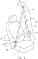
- FIG. 1 is a schematic, structural view shown a three-point safety belt of the present invention
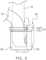
- FIG. 2 is a schematic, structural view shown a winder of FIG. 1
- FIG. 3 is a schematic, structural view shown a take-up state of the three-point safety belt of the present invention
- FIG. 4 is a schematic, structural view shown a draw-out state of the three-point safety belt of the present invention.
- the three-point safety belt of the present invention includes a belt body 10, a winder 20, a shoulder belt guide ring 30 and a lock tongue 40. Taken the front seat as an example, the winder 20 is fixed to B-pillar 50 of a vehicle body and located at a lower portion of the B-pillar 50.
- the fixing position of the winder 20 is close to a seat cushion 71 of a seat 70 and corresponds to the waist of the passenger.
- the shoulder belt guide ring 30 is fixed to the B-pillar 50 of the vehicle body and located at an upper portion of the B-pillar 50.
- the fixing position of the shoulder belt guide ring 30 is close to a top portion of a backrest 72 of the seat 70 and corresponds to shoulders of the passenger, that is to say, on the B-pillar 50, the winder 20 is located under the shoulder belt guide ring 30.
- the B-pillar 50 is located at one side of the seat 70, and a buckle 60 is disposed at the other side of the seat 70.
- the lock tongue 40 is sleeved on the belt body 10, and can be buckled with the buckle 60.
- the lock tongue 40 divides the belt body 10 into a shoulder belt 11 which is used for restraining the chest of a passenger and a waist belt 12 which is used for restraining the abdomen of the passenger.
- the shoulder belt 11 passes through the shoulder belt guide ring 30 and is connected with the winder 20.
- Two opposite ends of the belt body 10, i.e., a free end of the shoulder belt 11 which is away from the lock tongue 40 and a free end of the waist belt 12 which is away from the lock tongue 40 are both retracted within the same winder 20, and the winder 20 synchronously retracts or releases the shoulder belt 11 and waist belt 12.
- the three-point safety belt provided by the present invention could achieve a faster pre-tension speed and a greater pre-tension distance than the prior art, and the effect of the waist belt 12 on the passenger such as reeling, pre-tension and double pre-tension will not be delayed or weakened, which improves the safety performance of the vehicle. Since the shoulder belt 11 and the waist belt 12 are synchronously retracted by only one winder 20, the anchor point of the traditional safety belt is no longer needed, which reduces the cost of design, manufacture and assembly.
- the winder 20 includes a winder housing 21, a winder shaft 22 and a winding function box 23.
- One side of the winder housing 21 is fixed to the B-pillar 50 of the vehicle body.
- the winder shaft 22 is disposed in the winder housing 21, and the free ends of the shoulder belt 11 and the waist belt 12 are wound around the same winder shaft 22. In this embodiment, the free ends of the shoulder belt 11 and the waist belt 12 are wound around the winder shaft 22 after being stacked together.
- the winding function box 23 is disposed on the winder housing 21.
- the winding function box 23 is used for accommodating various types of functional mechanisms of the winder 20, such as a coil spring, a car-lock, a belt-lock, a pre-tensioner and electric pre-tensioner and so on.
- the winder 20 further includes a belt guide bracket 24.
- the belt guide bracket 24 is fixed to the winder housing 21 and located at one side from which the waist belt 12 is drawn out. When the belt body 10 is drawn out or taken up, the belt guide bracket 24 contacts with the waist belt 12 and guides the draw-out or take-up of the waist belt 12 so that the waist belt 12 could be drawn out or taken up freely.
- the belt guide bracket 24 includes a belt guide bracket base 241 and a guide shaft 242.
- the belt guide bracket base 241 is fixed on the winder housing 21.
- the guide shaft 242 is fixed on the belt guide bracket base 241.
- a roller (not shown) may be sleeved on the guide shaft 242.
- the waist belt 12 contacts with the roller, and drives the roller to rotate around the guide shaft 242.
- a distance between the lock tongue 40 and the winder 20 is smaller than a distance between the lock tongue 40 and the shoulder belt guide ring 30.
- the lock tongue 40 has a lower position on the belt body 10, and is closer to the lower portion of the belt body 10.
- the lock tongue 40 includes a tongue plate 41 and a lock tongue guide ring 42.
- the tongue plate 41 is fixed on the lock tongue guide ring 42.
- the lock tongue 40 is sleeved on the belt body 10 through the lock tongue guide ring 42.
- the belt body 10 further includes a lock tongue positioning bump 13 (shown in FIG. 3 ).
- the lock tongue guide ring 42 is sleeved on the belt body 10, the lock tongue guide ring 42 is located above the lock tongue positioning bump 13, preventing the lock tongue 40 from sliding downwardly along the belt body 10, so that the lock tongue 40 is positioned on the belt body 10 at a position above the lock tongue positioning bump 13.
- the lock tongue 40 When the three-point safety belt is worn, since the lock tongue 40 is located lower on the belt body 10 and closer to the lower portion of the belt body 10 than the prior art, it is only needed to pull the belt body 10 by the lock tongue 40 from the B-pillar 50 toward a central portion of the vehicle body, and insert the lock tongue 40 into the buckle 60 so that the three-point safety belt is worn without pulling the lock tongue 40 downwardly from top. Since the waist belt 12 and the shoulder belt 11 can be released from the winder 20 synchronously, when the belt body 10 is stretched, the lock tongue 40 does not need to slide with respect to the belt body 10 or only needs to slide a small distance to satisfy requirement of wearing the safety belt. Therefore, when wearing the three-point safety belt, the friction between the lock tongue 40 and the belt body 10 and the energy consumption are both small.
- the free ends of the shoulder belt 11 and the waist belt 12 are wound up on the same winder 20, realizing the synchronous release and retraction of the shoulder belt 11 and the waist belt 12. Therefore, the belt body 10 could be pulled by a small force, which improves the comfort of using the three-point safety belt.
- the synchronous retraction of the shoulder belt 11 and the waist belt 12 makes the effect of the winder 20 on the waist belt 12 can not be delayed or weakened, and makes the three-point safety belt could have a faster pre-tension speed and a larger pre-tension distance, and improves the safety performance of the three-point safety belt.
- the waist belt 12 is retracted in winder 20, eliminating the anchor point in the prior art, which further reduces the cost of design, manufacture and assembly of the three-point safety belt.
- the present invention also provides a vehicle which includes the three-point safety belt as described above.
- the free ends of the shoulder belt and the waist belt are wound up on the same winder, realizing the synchronous release and retraction of the shoulder belt and the waist belt. Therefore, the belt body could be pulled by a small force, which improves the comfort of using the three-point safety belt.
- the synchronous retraction of the shoulder belt and the waist belt makes the effect of the winder on the waist belt can not be delayed or weakened, and makes the three-point safety belt could have a faster pre-tension speed and a larger pre-tension distance, and improves the safety performance of the three-point safety belt.
- the waist belt is retracted in the winder, eliminating the anchor point in the prior art, which further reduces the cost of design, manufacture and assembly of the three-point safety belt.
Landscapes
- Engineering & Computer Science (AREA)
- Mechanical Engineering (AREA)
- Automotive Seat Belt Assembly (AREA)
- Emergency Lowering Means (AREA)
Abstract
Description
- The present application claims priority of Chinese Patent Application No.
201510455593.5, filed on July 29, 2015 - The present invention relates to vehicle techniques, and more particularly to a three-point safety belt and vehicle having the same.
- With development of vehicle technology, people's requirements in safety and comfort performance of vehicles has become higher and higher, and how to improve the safety and comfort performance of the vehicles has become one of the objects pursued by major vehicle manufacturers.
- Three-point safety belts are common safety devices in vehicles. Nowadays, the safety belts in vehicles are basically three-point safety belts (sometimes the humble two-point safety belts are used in the rear row). The traditional three-point safety belt includes a winder, a belt body, a shoulder belt guide ring, a lock tongue and a buckle. The shoulder belt guide ring is fixed on the vehicle body, the lock tongue is sleeved on the belt body, and the buckle is fixed to one side of the seat. After the lock tongue is inserted into the buckle, the buckling point (i.e., a fixing point of the lock tongue and the buckle) substantially divides the belt body into a shoulder belt which restrains the chest of a passenger and a waist belt which restrains the abdomen of the passenger. An end of the shoulder belt which is remote from the lock tongue passes through the shoulder belt guide ring and is wound around the winder. An end of the waist belt which is remote from the lock tongue is fixed to the vehicle body by an anchor point (i.e., a fixing point of the vehicle body and the end of the waist belt which is remote from the lock tongue). When the lock tongue of the three-point safety belt is inserted into the buckle, the three-point safety belt has four fixing points which includes the anchor point, the buckling point, the D-ring point (i.e., a contact point of the shoulder belt and the shoulder belt guide ring) and the winder point (i.e., a connection point of the winder and the end of the waist belt which is remote from the lock tongue).
- In order for convenience of wearing, the lock tongue is generally fixed to an upper portion (i.e., a position close to the shoulder belt guide ring) of the belt body through a lock tongue guide ring when the three-point safety belt is not worn. Therefore, when the lock tongue of the safety belt is pulled toward the buckle, the hand needs to be raised to a higher position to pull the belt body downwardly from top by the lock tongue. During the process of pulling the belt body by the lock tongue, the lock tongue will slide relative to the safety belt, which makes the lock tongue function as a movable pulley in a movable pulley system. However, pulling the movable pulley is a laborious process, and the fact that the belt body slides relative to the lock tongue increases the pulling resistance and energy consumption, which causes the process of wearing the safety belt to be a time-consuming, laborious and poor operation comfort process.
- When the three-point safety belt is worn, the belt body of the winder first exerts a force on the shoulder belt, and then transfers the force to the waist belt through the lock tongue guide ring. Since the belt body of the safety belt has a greater friction at the lock tongue guide ring (especially when confronts collision), the effect on the waist belt will be delayed and weakened. When the vehicle confronts collision, the winder exerts a small preload and a low pre-tension speed on the belt body, which greatly affects the safety performance of the vehicle.
- In addition, the anchor point (i.e., the fixing point of the vehicle body and the end of the waist belt which is remote from the lock tongue) of the current safety belt is fixed to the sill, which adds additional cost in design, manufacture and assembly.
- Accordingly, the present invention provides a three-point safety belt and a vehicle having the same, which is capable of improving comfort and safety performance of the three-point safety belt as well as decreasing the cost.
- The present invention provides a three-point safety belt which includes a belt body, a winder, a shoulder belt guide ring and a lock tongue. The winder and the shoulder belt guide ring are fixed to a vehicle body. The winder is located under the shoulder belt guide ring. The lock tongue is disposed on the belt body. The lock tongue divides the belt body into a shoulder belt for restraining the chest of a passenger and a waist belt for restraining the abdomen of the passenger. The shoulder belt passes through the shoulder belt guide ring. A free end of the shoulder belt which is away from the lock tongue and a free end of the waist belt which is away from the lock tongue are both retracted within the winder. The winder synchronously retracts or releases the shoulder belt and the waist belt.
- Furthermore, the winder includes a winder housing and a winder shaft. The winder housing is fixed to the vehicle body. The winder shaft is disposed in the winder housing. Both of the free ends of the shoulder belt and the waist belt are wound around the winder shaft.
- Furthermore, the free ends of the shoulder belt and the waist belt are wound around the winder shaft after being stacked together.
- Furthermore, the winder further includes a belt guide bracket. The belt guide bracket is fixed to the winder housing and located at one side from which the waist belt is drawn out. When the belt body is drawn out or taken up, the belt guide bracket contacts with the waist belt and guides the draw-out or take-up of the waist belt.
- Furthermore, the belt guide bracket includes a guide shaft and a belt guide bracket base. The belt guide bracket base is fixed on the winder housing. The guide shaft is fixed on the belt guide bracket base.
- Furthermore, a roller is sleeved on the guide shaft.
- Furthermore, when the belt body is not stretched, a distance between the lock tongue and the winder is smaller than a distance between the lock tongue and the shoulder belt guide ring.
- Furthermore, the lock tongue includes a tongue plate and a lock tongue guide ring. The lock tongue guide ring is sleeved on the belt body. The belt body further includes a lock tongue positioning bump. The lock tongue guide ring is located above the lock tongue positioning bump when it is sleeved on the belt body. The lock tongue is positioned on the belt body at a position above the lock tongue positioning bump.
- The present invention further provides a vehicle which includes either one of the three-point safety belt provided by the present invention.
- Furthermore, the vehicle includes a seat. The three-point safety belt is disposed at one side of the seat, and a buckle is disposed at the other side of the seat. A fixing position of the winder on the vehicle body is close to a seat cushion of the seat. A fixing position of the shoulder belt guide ring on the vehicle body is close to a top portion of a backrest of the seat.
- In the present invention, the free ends of the shoulder belt and the waist belt are wound up on the same winder, realizing the synchronous release and retraction of the shoulder belt and the waist belt. Therefore, the belt body could be pulled by a small force, which improves the comfort of using the three-point safety belt. The synchronous retraction of the shoulder belt and the waist belt makes the effect of the winder on the waist belt can not be delayed or weakened, and makes the three-point safety belt could have a faster pre-tension speed and a larger pre-tension distance, and improves the safety performance of the three-point safety belt. The waist belt is retracted in the winder, eliminating the anchor point in the prior art, which further reduces the cost of design, manufacture and assembly of the three-point safety belt.
-
-
FIG. 1 is a schematic, structural view shown a three-point safety belt of the present invention. -
FIG. 2 is a schematic, structural view shown a winder ofFIG. 1 . -
FIG. 3 is a schematic, structural view shown a take-up state of the three-point safety belt of the present invention. -
FIG. 4 is a schematic, structural view shown a draw-out state of the three-point safety belt of the present invention. - In order to further illustrate the aspects, techniques and effects of the present invention, the embodiments of the present invention will be described thoroughly in conjunction with the accompanying drawings.
-
FIG. 1 is a schematic, structural view shown a three-point safety belt of the present invention,FIG. 2 is a schematic, structural view shown a winder ofFIG. 1 ,FIG. 3 is a schematic, structural view shown a take-up state of the three-point safety belt of the present invention, andFIG. 4 is a schematic, structural view shown a draw-out state of the three-point safety belt of the present invention. Referring toFIG. 1 through FIG. 4 , the three-point safety belt of the present invention includes abelt body 10, awinder 20, a shoulderbelt guide ring 30 and alock tongue 40. Taken the front seat as an example, thewinder 20 is fixed to B-pillar 50 of a vehicle body and located at a lower portion of the B-pillar 50. The fixing position of thewinder 20 is close to aseat cushion 71 of aseat 70 and corresponds to the waist of the passenger. The shoulderbelt guide ring 30 is fixed to the B-pillar 50 of the vehicle body and located at an upper portion of the B-pillar 50. The fixing position of the shoulderbelt guide ring 30 is close to a top portion of abackrest 72 of theseat 70 and corresponds to shoulders of the passenger, that is to say, on the B-pillar 50, thewinder 20 is located under the shoulderbelt guide ring 30. The B-pillar 50 is located at one side of theseat 70, and abuckle 60 is disposed at the other side of theseat 70. Thelock tongue 40 is sleeved on thebelt body 10, and can be buckled with thebuckle 60. When the three-point safety belt is worn, thelock tongue 40 divides thebelt body 10 into ashoulder belt 11 which is used for restraining the chest of a passenger and awaist belt 12 which is used for restraining the abdomen of the passenger. Theshoulder belt 11 passes through the shoulderbelt guide ring 30 and is connected with thewinder 20. Two opposite ends of thebelt body 10, i.e., a free end of theshoulder belt 11 which is away from thelock tongue 40 and a free end of thewaist belt 12 which is away from thelock tongue 40 are both retracted within thesame winder 20, and thewinder 20 synchronously retracts or releases theshoulder belt 11 andwaist belt 12. - When the
belt body 10 is stretched, due to thewinder 20 could release theshoulder belt 11 and thewaist belt 12 synchronously, in case that the friction is unconsidered, if the safety belt is fastened, the force of pulling thebelt body 10 is only half of that of the traditional three-point safety belts, which improves the operational comfort. When thebelt body 10 of the three-point safety belt is pre-tightened or wound, due to thewinder 20 could retract theshoulder belt 11 and thewaist belt 12 synchronously, the three-point safety belt provided by the present invention could achieve a faster pre-tension speed and a greater pre-tension distance than the prior art, and the effect of thewaist belt 12 on the passenger such as reeling, pre-tension and double pre-tension will not be delayed or weakened, which improves the safety performance of the vehicle. Since theshoulder belt 11 and thewaist belt 12 are synchronously retracted by only onewinder 20, the anchor point of the traditional safety belt is no longer needed, which reduces the cost of design, manufacture and assembly. - More concretely, referring to
FIG. 1 andFIG. 2 , thewinder 20 includes awinder housing 21, awinder shaft 22 and a windingfunction box 23. One side of thewinder housing 21 is fixed to the B-pillar 50 of the vehicle body. Thewinder shaft 22 is disposed in thewinder housing 21, and the free ends of theshoulder belt 11 and thewaist belt 12 are wound around thesame winder shaft 22. In this embodiment, the free ends of theshoulder belt 11 and thewaist belt 12 are wound around thewinder shaft 22 after being stacked together. The windingfunction box 23 is disposed on thewinder housing 21. The windingfunction box 23 is used for accommodating various types of functional mechanisms of thewinder 20, such as a coil spring, a car-lock, a belt-lock, a pre-tensioner and electric pre-tensioner and so on. - Furthermore, in order to reduce the friction between the
waist belt 12 and thewinder housing 21, and provide a safety protection for thewaist belt 12, thewinder 20 further includes abelt guide bracket 24. Thebelt guide bracket 24 is fixed to thewinder housing 21 and located at one side from which thewaist belt 12 is drawn out. When thebelt body 10 is drawn out or taken up, thebelt guide bracket 24 contacts with thewaist belt 12 and guides the draw-out or take-up of thewaist belt 12 so that thewaist belt 12 could be drawn out or taken up freely. More concretely, thebelt guide bracket 24 includes a beltguide bracket base 241 and aguide shaft 242. The beltguide bracket base 241 is fixed on thewinder housing 21. Theguide shaft 242 is fixed on the beltguide bracket base 241. When thebelt body 10 is pulled out or retracted, thewaist belt 12 slides on theguide shaft 242. In order to further reduce the friction between thewaist belt 12 and thewinder housing 21, a roller (not shown) may be sleeved on theguide shaft 242. When thebelt body 10 is pulled out or retracted, thewaist belt 12 contacts with the roller, and drives the roller to rotate around theguide shaft 242. - Referring to
FIG. 3 andFIG. 4 , when the three-point safety belt is not worn, i.e., when thebelt body 10 is not pulled out and stays in the natural position, a distance between thelock tongue 40 and thewinder 20 is smaller than a distance between thelock tongue 40 and the shoulderbelt guide ring 30. As compared with the prior art, thelock tongue 40 has a lower position on thebelt body 10, and is closer to the lower portion of thebelt body 10. When the safety belt is fastened, it is convenient for the passenger to grasp thelock tongue 40 and pull thebelt body 10. - Furthermore, the
lock tongue 40 includes atongue plate 41 and a locktongue guide ring 42. Thetongue plate 41 is fixed on the locktongue guide ring 42. Thelock tongue 40 is sleeved on thebelt body 10 through the locktongue guide ring 42. Thebelt body 10 further includes a lock tongue positioning bump 13 (shown inFIG. 3 ). When the locktongue guide ring 42 is sleeved on thebelt body 10, the locktongue guide ring 42 is located above the locktongue positioning bump 13, preventing thelock tongue 40 from sliding downwardly along thebelt body 10, so that thelock tongue 40 is positioned on thebelt body 10 at a position above the locktongue positioning bump 13. - When the three-point safety belt is worn, since the
lock tongue 40 is located lower on thebelt body 10 and closer to the lower portion of thebelt body 10 than the prior art, it is only needed to pull thebelt body 10 by thelock tongue 40 from the B-pillar 50 toward a central portion of the vehicle body, and insert thelock tongue 40 into thebuckle 60 so that the three-point safety belt is worn without pulling thelock tongue 40 downwardly from top. Since thewaist belt 12 and theshoulder belt 11 can be released from thewinder 20 synchronously, when thebelt body 10 is stretched, thelock tongue 40 does not need to slide with respect to thebelt body 10 or only needs to slide a small distance to satisfy requirement of wearing the safety belt. Therefore, when wearing the three-point safety belt, the friction between thelock tongue 40 and thebelt body 10 and the energy consumption are both small. - In summary, in the present invention, the free ends of the
shoulder belt 11 and thewaist belt 12 are wound up on thesame winder 20, realizing the synchronous release and retraction of theshoulder belt 11 and thewaist belt 12. Therefore, thebelt body 10 could be pulled by a small force, which improves the comfort of using the three-point safety belt. The synchronous retraction of theshoulder belt 11 and thewaist belt 12 makes the effect of thewinder 20 on thewaist belt 12 can not be delayed or weakened, and makes the three-point safety belt could have a faster pre-tension speed and a larger pre-tension distance, and improves the safety performance of the three-point safety belt. Thewaist belt 12 is retracted inwinder 20, eliminating the anchor point in the prior art, which further reduces the cost of design, manufacture and assembly of the three-point safety belt. - The present invention also provides a vehicle which includes the three-point safety belt as described above.
- The descriptions above are embodiments of the present invention only, and are not used, by any way, to limit the present invention. Although the present invention has been described with reference to the above embodiments, those embodiments are not used to limit the present invention, it will be apparent to anyone of ordinary skill in the art that slight changes or modifications to the described embodiments may be made to become equivalent embodiments without departing from the technique scope of the present invention. On the contrary, any slight and simple changes, equivalent variations and modifications according to the disclosure of the present invention should fall within the technique scope of the present invention.
- In embodiments of the present invention, the free ends of the shoulder belt and the waist belt are wound up on the same winder, realizing the synchronous release and retraction of the shoulder belt and the waist belt. Therefore, the belt body could be pulled by a small force, which improves the comfort of using the three-point safety belt. The synchronous retraction of the shoulder belt and the waist belt makes the effect of the winder on the waist belt can not be delayed or weakened, and makes the three-point safety belt could have a faster pre-tension speed and a larger pre-tension distance, and improves the safety performance of the three-point safety belt. The waist belt is retracted in the winder, eliminating the anchor point in the prior art, which further reduces the cost of design, manufacture and assembly of the three-point safety belt.
Claims (10)
- A three-point safety belt, comprising a belt body (10), a winder (20), a shoulder belt guide ring (30) and a lock tongue (40), the winder (20) and the shoulder belt guide ring (30) being fixed to a vehicle body, the winder (20) being located under the shoulder belt guide ring (30), the lock tongue (40) being disposed on the belt body (10), the lock tongue (40) dividing the belt body (10) into a shoulder belt (11) for restraining the chest of a passenger and a waist belt (12) for restraining the abdomen of the passenger, the shoulder belt (11) passing through the shoulder belt guide ring (30), characterized by a free end of the shoulder belt (11) which is away from the lock tongue (40) and a free end of the waist belt (12) which is away from the lock tongue (40) are both retracted within the same winder (20), and the winder (20) synchronously retracts or releases the shoulder belt (11) and the waist belt (12).
- The three-point safety belt of claim 1, wherein the winder (20) comprises a winder housing (21) and a winder shaft (22), the winder housing (21) is fixed to the vehicle body, the winder shaft (22) is disposed in the winder housing (21), both of the free ends of the shoulder belt (11) and the waist belt (12) are wound around the winder shaft (22).
- The three-point safety belt of claim 2, wherein the free ends of the shoulder belt (11) and the waist belt (12) are wound around the winder shaft (22) after being stacked together.
- The three-point safety belt of claim 2, wherein the winder (20) further comprises a belt guide bracket (24), the belt guide bracket (24) is fixed to the winder housing (21) and located at one side from which the waist belt (12) is drawn out, when the belt body (10) is drawn out or taken up, the belt guide bracket (24) contacts with the waist belt (12) and guides the draw-out or take-up of the waist belt (12).
- The three-point safety belt of claim 4, wherein the belt guide bracket (24) comprises a guide shaft (242) and a belt guide bracket base (241), the belt guide bracket base (241) is fixed on the winder housing (21), the guide shaft (242) is fixed on the belt guide bracket base (241).
- The three-point safety belt of claim 5, wherein a roller is sleeved on the guide shaft (242).
- The three-point safety belt of claim 1, wherein when the belt body (10) is not stretched, a distance between the lock tongue (40) and the winder (20) is smaller than a distance between the lock tongue (40) and the shoulder belt guide ring (30).
- The three-point safety belt of claim 7, wherein the lock tongue (40) comprises a tongue plate (41) and a lock tongue guide ring (42), the lock tongue guide ring (42) is sleeved on the belt body (10), the belt body (10) further comprises a lock tongue positioning bump (13), the lock tongue guide ring (42) is located above the lock tongue positioning bump (13) when it is sleeved on the belt body (10), the lock tongue (40) is positioned on the belt body (10) at a position above the lock tongue positioning bump (13).
- A vehicle, comprising the three-point safety belt of either one of claims 1 to 8.
- The vehicle of claim 9, wherein the vehicle comprises a seat (70), the three-point safety belt is disposed at one side of the seat (70), a buckle (60) is disposed at the other side of the seat (70), a fixing position of the winder (20) on the vehicle body is close to a seat cushion (71) of the seat (70), a fixing position of the shoulder belt guide ring (30) on the vehicle body is close to a top portion of a backrest (72) of the seat (70).
Applications Claiming Priority (2)
| Application Number | Priority Date | Filing Date | Title |
|---|---|---|---|
| CN201510455593.5A CN105150996A (en) | 2015-07-29 | 2015-07-29 | Three-point type safety belt and vehicle with same |
| PCT/CN2016/085068 WO2017016320A1 (en) | 2015-07-29 | 2016-06-07 | Three-point safety belt and vehicle having same |
Publications (3)
| Publication Number | Publication Date |
|---|---|
| EP3315365A1 true EP3315365A1 (en) | 2018-05-02 |
| EP3315365A4 EP3315365A4 (en) | 2018-07-04 |
| EP3315365B1 EP3315365B1 (en) | 2019-08-07 |
Family
ID=54792162
Family Applications (1)
| Application Number | Title | Priority Date | Filing Date |
|---|---|---|---|
| EP16829687.9A Active EP3315365B1 (en) | 2015-07-29 | 2016-06-07 | Three-point safety belt and vehicle having same |
Country Status (4)
| Country | Link |
|---|---|
| US (1) | US10562487B2 (en) |
| EP (1) | EP3315365B1 (en) |
| CN (1) | CN105150996A (en) |
| WO (1) | WO2017016320A1 (en) |
Families Citing this family (4)
| Publication number | Priority date | Publication date | Assignee | Title |
|---|---|---|---|---|
| CN105150996A (en) * | 2015-07-29 | 2015-12-16 | 浙江吉利汽车研究院有限公司 | Three-point type safety belt and vehicle with same |
| CN107757545A (en) * | 2017-11-12 | 2018-03-06 | 李勇 | Passenger vehicle forces closing of safety belt |
| KR102749106B1 (en) * | 2022-07-18 | 2024-12-31 | 아우토리브 디벨롭먼트 아베 | Seat belt retractor |
| KR102673182B1 (en) * | 2022-07-18 | 2024-06-10 | 아우토리브 디벨롭먼트 아베 | Seatbelt retractor with webbing guide |
Family Cites Families (21)
| Publication number | Priority date | Publication date | Assignee | Title |
|---|---|---|---|---|
| US3549203A (en) * | 1969-05-01 | 1970-12-22 | American Safety Equip | Retractable safety belt restraint system |
| JPS5259423A (en) * | 1975-11-11 | 1977-05-16 | Toyota Motor Corp | Seat belt for vehicles |
| US4101170A (en) * | 1976-02-19 | 1978-07-18 | Toyota Jidosha Kogyo Kabushiki Kaisha | Seat belt device for use in vehicle |
| US4113280A (en) * | 1976-02-19 | 1978-09-12 | Toyota Jidosha Kogyo Kabushiki Kaisha | Seat belt device for use in vehicle |
| US4065156A (en) * | 1976-04-12 | 1977-12-27 | Toyota Jidosha Kogyo Kabushiki Kaisha | Seat belt system |
| JPS5320724U (en) * | 1976-07-30 | 1978-02-22 | ||
| JPS5320734U (en) * | 1976-08-02 | 1978-02-22 | ||
| JPS5320733U (en) * | 1976-08-02 | 1978-02-22 | ||
| JPS5322436U (en) * | 1976-08-03 | 1978-02-24 | ||
| JPS5324032U (en) * | 1976-08-06 | 1978-03-01 | ||
| JPS5355113U (en) * | 1976-10-14 | 1978-05-11 | ||
| JPS5418531A (en) * | 1977-07-13 | 1979-02-10 | Mitsubishi Motors Corp | Seat belt |
| JPS54118721U (en) * | 1978-02-09 | 1979-08-20 | ||
| JPS5636356U (en) * | 1979-08-31 | 1981-04-08 | ||
| US4646987A (en) * | 1985-08-30 | 1987-03-03 | Peterson Edwin R | Take-up reel for tape containing conductors |
| US4896844A (en) * | 1987-10-19 | 1990-01-30 | Irvin Industries, Inc. | Dual spool retractor with comfort limiting mechanism |
| DE19915275A1 (en) * | 1999-04-03 | 2000-10-05 | Volkswagen Ag | Safety belt arrangement for motor vehicle seats has threaded bolt on one belt for intentional release of connection between automatic belt tensioner/roller units |
| JP2007062421A (en) | 2005-08-29 | 2007-03-15 | Takata Corp | Seat belt device and vehicle |
| DE102012008507A1 (en) * | 2012-04-27 | 2013-10-31 | Autoliv Development Ab | Safety belt device used in vehicle, has shoulder strap and lap belt which are wound by force acted by using single winding element of retractor |
| CN104002759B (en) * | 2014-06-06 | 2016-08-31 | 中国汽车技术研究中心 | Double-pretension type safety belt retractor |
| CN105150996A (en) | 2015-07-29 | 2015-12-16 | 浙江吉利汽车研究院有限公司 | Three-point type safety belt and vehicle with same |
-
2015
- 2015-07-29 CN CN201510455593.5A patent/CN105150996A/en active Pending
-
2016
- 2016-06-07 WO PCT/CN2016/085068 patent/WO2017016320A1/en not_active Ceased
- 2016-06-07 EP EP16829687.9A patent/EP3315365B1/en active Active
- 2016-06-07 US US15/745,124 patent/US10562487B2/en active Active
Also Published As
| Publication number | Publication date |
|---|---|
| CN105150996A (en) | 2015-12-16 |
| WO2017016320A1 (en) | 2017-02-02 |
| EP3315365A4 (en) | 2018-07-04 |
| US10562487B2 (en) | 2020-02-18 |
| US20180208152A1 (en) | 2018-07-26 |
| EP3315365B1 (en) | 2019-08-07 |
Similar Documents
| Publication | Publication Date | Title |
|---|---|---|
| EP3315365B1 (en) | Three-point safety belt and vehicle having same | |
| US9615632B2 (en) | Tongue and seat belt device using same | |
| US9988012B2 (en) | Seat belt system | |
| CN101516691A (en) | Seatbelt retracting device, seatbelt retracting method, computer program, and seatbelt system | |
| CN107933494B (en) | Pretensioner and seatbelt assembly including the same | |
| KR101788193B1 (en) | Belt guide device and safety belt assembly having the same | |
| JPWO2012090329A1 (en) | Seat belt device | |
| US9204691B2 (en) | Tongue and seat belt device using the same | |
| US4176808A (en) | Passenger restraining seat belt retractor | |
| JP2011152852A (en) | Seat belt device | |
| US9340181B2 (en) | Belt member and seatbelt apparatus including the belt member | |
| JP2016060458A (en) | Belt insertion tool and seat belt device | |
| JP6483982B2 (en) | Belt insertion tool and seat belt device | |
| JP2011016480A (en) | Seat belt device | |
| US3459440A (en) | Belt retracting device | |
| US4099684A (en) | Seat belt system | |
| KR101305563B1 (en) | Seat belt apparatus for vehicle | |
| JP2014181011A (en) | Seat belt device | |
| JP2013060113A (en) | Tongue for seat belt device and the seat belt device | |
| JP6273926B2 (en) | Seat belt device | |
| JP5314442B2 (en) | Seat belt device with pretensioner | |
| CN209079858U (en) | A kind of car belt convenient for adjusting | |
| KR102585755B1 (en) | Seat belt safety apparatus for vehicle | |
| CN106828404A (en) | Reel double end pretension coiler and safety belt | |
| JP2012020606A (en) | Seat belt device |
Legal Events
| Date | Code | Title | Description |
|---|---|---|---|
| STAA | Information on the status of an ep patent application or granted ep patent |
Free format text: STATUS: THE INTERNATIONAL PUBLICATION HAS BEEN MADE |
|
| PUAI | Public reference made under article 153(3) epc to a published international application that has entered the european phase |
Free format text: ORIGINAL CODE: 0009012 |
|
| STAA | Information on the status of an ep patent application or granted ep patent |
Free format text: STATUS: REQUEST FOR EXAMINATION WAS MADE |
|
| 17P | Request for examination filed |
Effective date: 20180126 |
|
| AK | Designated contracting states |
Kind code of ref document: A1 Designated state(s): AL AT BE BG CH CY CZ DE DK EE ES FI FR GB GR HR HU IE IS IT LI LT LU LV MC MK MT NL NO PL PT RO RS SE SI SK SM TR |
|
| AX | Request for extension of the european patent |
Extension state: BA ME |
|
| A4 | Supplementary search report drawn up and despatched |
Effective date: 20180606 |
|
| RIC1 | Information provided on ipc code assigned before grant |
Ipc: B60R 22/02 20060101ALI20180530BHEP Ipc: B60R 22/34 20060101AFI20180530BHEP |
|
| STAA | Information on the status of an ep patent application or granted ep patent |
Free format text: STATUS: EXAMINATION IS IN PROGRESS |
|
| 17Q | First examination report despatched |
Effective date: 20181004 |
|
| DAV | Request for validation of the european patent (deleted) | ||
| DAX | Request for extension of the european patent (deleted) | ||
| GRAP | Despatch of communication of intention to grant a patent |
Free format text: ORIGINAL CODE: EPIDOSNIGR1 |
|
| STAA | Information on the status of an ep patent application or granted ep patent |
Free format text: STATUS: GRANT OF PATENT IS INTENDED |
|
| RIC1 | Information provided on ipc code assigned before grant |
Ipc: B60R 22/34 20060101AFI20190212BHEP Ipc: B65H 75/44 20060101ALI20190212BHEP Ipc: B60R 22/02 20060101ALI20190212BHEP |
|
| INTG | Intention to grant announced |
Effective date: 20190308 |
|
| GRAS | Grant fee paid |
Free format text: ORIGINAL CODE: EPIDOSNIGR3 |
|
| GRAA | (expected) grant |
Free format text: ORIGINAL CODE: 0009210 |
|
| STAA | Information on the status of an ep patent application or granted ep patent |
Free format text: STATUS: THE PATENT HAS BEEN GRANTED |
|
| AK | Designated contracting states |
Kind code of ref document: B1 Designated state(s): AL AT BE BG CH CY CZ DE DK EE ES FI FR GB GR HR HU IE IS IT LI LT LU LV MC MK MT NL NO PL PT RO RS SE SI SK SM TR |
|
| REG | Reference to a national code |
Ref country code: GB Ref legal event code: FG4D |
|
| REG | Reference to a national code |
Ref country code: CH Ref legal event code: EP Ref country code: AT Ref legal event code: REF Ref document number: 1163352 Country of ref document: AT Kind code of ref document: T Effective date: 20190815 |
|
| REG | Reference to a national code |
Ref country code: DE Ref legal event code: R096 Ref document number: 602016018385 Country of ref document: DE |
|
| REG | Reference to a national code |
Ref country code: IE Ref legal event code: FG4D |
|
| REG | Reference to a national code |
Ref country code: NL Ref legal event code: MP Effective date: 20190807 |
|
| REG | Reference to a national code |
Ref country code: LT Ref legal event code: MG4D |
|
| PG25 | Lapsed in a contracting state [announced via postgrant information from national office to epo] |
Ref country code: FI Free format text: LAPSE BECAUSE OF FAILURE TO SUBMIT A TRANSLATION OF THE DESCRIPTION OR TO PAY THE FEE WITHIN THE PRESCRIBED TIME-LIMIT Effective date: 20190807 Ref country code: LT Free format text: LAPSE BECAUSE OF FAILURE TO SUBMIT A TRANSLATION OF THE DESCRIPTION OR TO PAY THE FEE WITHIN THE PRESCRIBED TIME-LIMIT Effective date: 20190807 Ref country code: NL Free format text: LAPSE BECAUSE OF FAILURE TO SUBMIT A TRANSLATION OF THE DESCRIPTION OR TO PAY THE FEE WITHIN THE PRESCRIBED TIME-LIMIT Effective date: 20190807 Ref country code: BG Free format text: LAPSE BECAUSE OF FAILURE TO SUBMIT A TRANSLATION OF THE DESCRIPTION OR TO PAY THE FEE WITHIN THE PRESCRIBED TIME-LIMIT Effective date: 20191107 Ref country code: PT Free format text: LAPSE BECAUSE OF FAILURE TO SUBMIT A TRANSLATION OF THE DESCRIPTION OR TO PAY THE FEE WITHIN THE PRESCRIBED TIME-LIMIT Effective date: 20191209 Ref country code: NO Free format text: LAPSE BECAUSE OF FAILURE TO SUBMIT A TRANSLATION OF THE DESCRIPTION OR TO PAY THE FEE WITHIN THE PRESCRIBED TIME-LIMIT Effective date: 20191107 Ref country code: HR Free format text: LAPSE BECAUSE OF FAILURE TO SUBMIT A TRANSLATION OF THE DESCRIPTION OR TO PAY THE FEE WITHIN THE PRESCRIBED TIME-LIMIT Effective date: 20190807 Ref country code: SE Free format text: LAPSE BECAUSE OF FAILURE TO SUBMIT A TRANSLATION OF THE DESCRIPTION OR TO PAY THE FEE WITHIN THE PRESCRIBED TIME-LIMIT Effective date: 20190807 |
|
| REG | Reference to a national code |
Ref country code: AT Ref legal event code: MK05 Ref document number: 1163352 Country of ref document: AT Kind code of ref document: T Effective date: 20190807 |
|
| PG25 | Lapsed in a contracting state [announced via postgrant information from national office to epo] |
Ref country code: RS Free format text: LAPSE BECAUSE OF FAILURE TO SUBMIT A TRANSLATION OF THE DESCRIPTION OR TO PAY THE FEE WITHIN THE PRESCRIBED TIME-LIMIT Effective date: 20190807 Ref country code: GR Free format text: LAPSE BECAUSE OF FAILURE TO SUBMIT A TRANSLATION OF THE DESCRIPTION OR TO PAY THE FEE WITHIN THE PRESCRIBED TIME-LIMIT Effective date: 20191108 Ref country code: IS Free format text: LAPSE BECAUSE OF FAILURE TO SUBMIT A TRANSLATION OF THE DESCRIPTION OR TO PAY THE FEE WITHIN THE PRESCRIBED TIME-LIMIT Effective date: 20191207 Ref country code: AL Free format text: LAPSE BECAUSE OF FAILURE TO SUBMIT A TRANSLATION OF THE DESCRIPTION OR TO PAY THE FEE WITHIN THE PRESCRIBED TIME-LIMIT Effective date: 20190807 Ref country code: ES Free format text: LAPSE BECAUSE OF FAILURE TO SUBMIT A TRANSLATION OF THE DESCRIPTION OR TO PAY THE FEE WITHIN THE PRESCRIBED TIME-LIMIT Effective date: 20190807 Ref country code: LV Free format text: LAPSE BECAUSE OF FAILURE TO SUBMIT A TRANSLATION OF THE DESCRIPTION OR TO PAY THE FEE WITHIN THE PRESCRIBED TIME-LIMIT Effective date: 20190807 |
|
| PG25 | Lapsed in a contracting state [announced via postgrant information from national office to epo] |
Ref country code: TR Free format text: LAPSE BECAUSE OF FAILURE TO SUBMIT A TRANSLATION OF THE DESCRIPTION OR TO PAY THE FEE WITHIN THE PRESCRIBED TIME-LIMIT Effective date: 20190807 |
|
| PG25 | Lapsed in a contracting state [announced via postgrant information from national office to epo] |
Ref country code: EE Free format text: LAPSE BECAUSE OF FAILURE TO SUBMIT A TRANSLATION OF THE DESCRIPTION OR TO PAY THE FEE WITHIN THE PRESCRIBED TIME-LIMIT Effective date: 20190807 Ref country code: PL Free format text: LAPSE BECAUSE OF FAILURE TO SUBMIT A TRANSLATION OF THE DESCRIPTION OR TO PAY THE FEE WITHIN THE PRESCRIBED TIME-LIMIT Effective date: 20190807 Ref country code: AT Free format text: LAPSE BECAUSE OF FAILURE TO SUBMIT A TRANSLATION OF THE DESCRIPTION OR TO PAY THE FEE WITHIN THE PRESCRIBED TIME-LIMIT Effective date: 20190807 Ref country code: IT Free format text: LAPSE BECAUSE OF FAILURE TO SUBMIT A TRANSLATION OF THE DESCRIPTION OR TO PAY THE FEE WITHIN THE PRESCRIBED TIME-LIMIT Effective date: 20190807 Ref country code: DK Free format text: LAPSE BECAUSE OF FAILURE TO SUBMIT A TRANSLATION OF THE DESCRIPTION OR TO PAY THE FEE WITHIN THE PRESCRIBED TIME-LIMIT Effective date: 20190807 Ref country code: RO Free format text: LAPSE BECAUSE OF FAILURE TO SUBMIT A TRANSLATION OF THE DESCRIPTION OR TO PAY THE FEE WITHIN THE PRESCRIBED TIME-LIMIT Effective date: 20190807 |
|
| PG25 | Lapsed in a contracting state [announced via postgrant information from national office to epo] |
Ref country code: IS Free format text: LAPSE BECAUSE OF FAILURE TO SUBMIT A TRANSLATION OF THE DESCRIPTION OR TO PAY THE FEE WITHIN THE PRESCRIBED TIME-LIMIT Effective date: 20200224 Ref country code: SK Free format text: LAPSE BECAUSE OF FAILURE TO SUBMIT A TRANSLATION OF THE DESCRIPTION OR TO PAY THE FEE WITHIN THE PRESCRIBED TIME-LIMIT Effective date: 20190807 Ref country code: CZ Free format text: LAPSE BECAUSE OF FAILURE TO SUBMIT A TRANSLATION OF THE DESCRIPTION OR TO PAY THE FEE WITHIN THE PRESCRIBED TIME-LIMIT Effective date: 20190807 Ref country code: SM Free format text: LAPSE BECAUSE OF FAILURE TO SUBMIT A TRANSLATION OF THE DESCRIPTION OR TO PAY THE FEE WITHIN THE PRESCRIBED TIME-LIMIT Effective date: 20190807 |
|
| REG | Reference to a national code |
Ref country code: DE Ref legal event code: R097 Ref document number: 602016018385 Country of ref document: DE |
|
| PLBE | No opposition filed within time limit |
Free format text: ORIGINAL CODE: 0009261 |
|
| STAA | Information on the status of an ep patent application or granted ep patent |
Free format text: STATUS: NO OPPOSITION FILED WITHIN TIME LIMIT |
|
| PG2D | Information on lapse in contracting state deleted |
Ref country code: IS |
|
| 26N | No opposition filed |
Effective date: 20200603 |
|
| PG25 | Lapsed in a contracting state [announced via postgrant information from national office to epo] |
Ref country code: SI Free format text: LAPSE BECAUSE OF FAILURE TO SUBMIT A TRANSLATION OF THE DESCRIPTION OR TO PAY THE FEE WITHIN THE PRESCRIBED TIME-LIMIT Effective date: 20190807 |
|
| PG25 | Lapsed in a contracting state [announced via postgrant information from national office to epo] |
Ref country code: MC Free format text: LAPSE BECAUSE OF FAILURE TO SUBMIT A TRANSLATION OF THE DESCRIPTION OR TO PAY THE FEE WITHIN THE PRESCRIBED TIME-LIMIT Effective date: 20190807 |
|
| REG | Reference to a national code |
Ref country code: CH Ref legal event code: PL |
|
| PG25 | Lapsed in a contracting state [announced via postgrant information from national office to epo] |
Ref country code: LU Free format text: LAPSE BECAUSE OF NON-PAYMENT OF DUE FEES Effective date: 20200607 |
|
| REG | Reference to a national code |
Ref country code: BE Ref legal event code: MM Effective date: 20200630 |
|
| PG25 | Lapsed in a contracting state [announced via postgrant information from national office to epo] |
Ref country code: CH Free format text: LAPSE BECAUSE OF NON-PAYMENT OF DUE FEES Effective date: 20200630 Ref country code: LI Free format text: LAPSE BECAUSE OF NON-PAYMENT OF DUE FEES Effective date: 20200630 Ref country code: IE Free format text: LAPSE BECAUSE OF NON-PAYMENT OF DUE FEES Effective date: 20200607 |
|
| PG25 | Lapsed in a contracting state [announced via postgrant information from national office to epo] |
Ref country code: BE Free format text: LAPSE BECAUSE OF NON-PAYMENT OF DUE FEES Effective date: 20200630 |
|
| PG25 | Lapsed in a contracting state [announced via postgrant information from national office to epo] |
Ref country code: MT Free format text: LAPSE BECAUSE OF FAILURE TO SUBMIT A TRANSLATION OF THE DESCRIPTION OR TO PAY THE FEE WITHIN THE PRESCRIBED TIME-LIMIT Effective date: 20190807 Ref country code: CY Free format text: LAPSE BECAUSE OF FAILURE TO SUBMIT A TRANSLATION OF THE DESCRIPTION OR TO PAY THE FEE WITHIN THE PRESCRIBED TIME-LIMIT Effective date: 20190807 |
|
| PG25 | Lapsed in a contracting state [announced via postgrant information from national office to epo] |
Ref country code: MK Free format text: LAPSE BECAUSE OF FAILURE TO SUBMIT A TRANSLATION OF THE DESCRIPTION OR TO PAY THE FEE WITHIN THE PRESCRIBED TIME-LIMIT Effective date: 20190807 |
|
| PGFP | Annual fee paid to national office [announced via postgrant information from national office to epo] |
Ref country code: DE Payment date: 20250618 Year of fee payment: 10 |
|
| PGFP | Annual fee paid to national office [announced via postgrant information from national office to epo] |
Ref country code: GB Payment date: 20250402 Year of fee payment: 10 |
|
| PGFP | Annual fee paid to national office [announced via postgrant information from national office to epo] |
Ref country code: FR Payment date: 20250515 Year of fee payment: 10 |