EP3315264A1 - Power tool - Google Patents
Power tool Download PDFInfo
- Publication number
- EP3315264A1 EP3315264A1 EP17187441.5A EP17187441A EP3315264A1 EP 3315264 A1 EP3315264 A1 EP 3315264A1 EP 17187441 A EP17187441 A EP 17187441A EP 3315264 A1 EP3315264 A1 EP 3315264A1
- Authority
- EP
- European Patent Office
- Prior art keywords
- housing part
- housing
- power tool
- rail
- battery pack
- Prior art date
- Legal status (The legal status is an assumption and is not a legal conclusion. Google has not performed a legal analysis and makes no representation as to the accuracy of the status listed.)
- Withdrawn
Links
Images







Classifications
-
- B—PERFORMING OPERATIONS; TRANSPORTING
- B24—GRINDING; POLISHING
- B24B—MACHINES, DEVICES, OR PROCESSES FOR GRINDING OR POLISHING; DRESSING OR CONDITIONING OF ABRADING SURFACES; FEEDING OF GRINDING, POLISHING, OR LAPPING AGENTS
- B24B23/00—Portable grinding machines, e.g. hand-guided; Accessories therefor
- B24B23/02—Portable grinding machines, e.g. hand-guided; Accessories therefor with rotating grinding tools; Accessories therefor
-
- B—PERFORMING OPERATIONS; TRANSPORTING
- B24—GRINDING; POLISHING
- B24B—MACHINES, DEVICES, OR PROCESSES FOR GRINDING OR POLISHING; DRESSING OR CONDITIONING OF ABRADING SURFACES; FEEDING OF GRINDING, POLISHING, OR LAPPING AGENTS
- B24B47/00—Drives or gearings; Equipment therefor
-
- B—PERFORMING OPERATIONS; TRANSPORTING
- B24—GRINDING; POLISHING
- B24B—MACHINES, DEVICES, OR PROCESSES FOR GRINDING OR POLISHING; DRESSING OR CONDITIONING OF ABRADING SURFACES; FEEDING OF GRINDING, POLISHING, OR LAPPING AGENTS
- B24B47/00—Drives or gearings; Equipment therefor
- B24B47/10—Drives or gearings; Equipment therefor for rotating or reciprocating working-spindles carrying grinding wheels or workpieces
- B24B47/12—Drives or gearings; Equipment therefor for rotating or reciprocating working-spindles carrying grinding wheels or workpieces by mechanical gearing or electric power
-
- B—PERFORMING OPERATIONS; TRANSPORTING
- B24—GRINDING; POLISHING
- B24B—MACHINES, DEVICES, OR PROCESSES FOR GRINDING OR POLISHING; DRESSING OR CONDITIONING OF ABRADING SURFACES; FEEDING OF GRINDING, POLISHING, OR LAPPING AGENTS
- B24B55/00—Safety devices for grinding or polishing machines; Accessories fitted to grinding or polishing machines for keeping tools or parts of the machine in good working condition
- B24B55/06—Dust extraction equipment on grinding or polishing machines
- B24B55/10—Dust extraction equipment on grinding or polishing machines specially designed for portable grinding machines, e.g. hand-guided
- B24B55/102—Dust extraction equipment on grinding or polishing machines specially designed for portable grinding machines, e.g. hand-guided with rotating tools
-
- B—PERFORMING OPERATIONS; TRANSPORTING
- B25—HAND TOOLS; PORTABLE POWER-DRIVEN TOOLS; MANIPULATORS
- B25F—COMBINATION OR MULTI-PURPOSE TOOLS NOT OTHERWISE PROVIDED FOR; DETAILS OR COMPONENTS OF PORTABLE POWER-DRIVEN TOOLS NOT PARTICULARLY RELATED TO THE OPERATIONS PERFORMED AND NOT OTHERWISE PROVIDED FOR
- B25F5/00—Details or components of portable power-driven tools not particularly related to the operations performed and not otherwise provided for
- B25F5/02—Construction of casings, bodies or handles
-
- H—ELECTRICITY
- H01—ELECTRIC ELEMENTS
- H01M—PROCESSES OR MEANS, e.g. BATTERIES, FOR THE DIRECT CONVERSION OF CHEMICAL ENERGY INTO ELECTRICAL ENERGY
- H01M50/00—Constructional details or processes of manufacture of the non-active parts of electrochemical cells other than fuel cells, e.g. hybrid cells
- H01M50/20—Mountings; Secondary casings or frames; Racks, modules or packs; Suspension devices; Shock absorbers; Transport or carrying devices; Holders
- H01M50/244—Secondary casings; Racks; Suspension devices; Carrying devices; Holders characterised by their mounting method
-
- H—ELECTRICITY
- H01—ELECTRIC ELEMENTS
- H01M—PROCESSES OR MEANS, e.g. BATTERIES, FOR THE DIRECT CONVERSION OF CHEMICAL ENERGY INTO ELECTRICAL ENERGY
- H01M50/00—Constructional details or processes of manufacture of the non-active parts of electrochemical cells other than fuel cells, e.g. hybrid cells
- H01M50/20—Mountings; Secondary casings or frames; Racks, modules or packs; Suspension devices; Shock absorbers; Transport or carrying devices; Holders
- H01M50/296—Mountings; Secondary casings or frames; Racks, modules or packs; Suspension devices; Shock absorbers; Transport or carrying devices; Holders characterised by terminals of battery packs
-
- H—ELECTRICITY
- H01—ELECTRIC ELEMENTS
- H01M—PROCESSES OR MEANS, e.g. BATTERIES, FOR THE DIRECT CONVERSION OF CHEMICAL ENERGY INTO ELECTRICAL ENERGY
- H01M50/00—Constructional details or processes of manufacture of the non-active parts of electrochemical cells other than fuel cells, e.g. hybrid cells
- H01M50/50—Current conducting connections for cells or batteries
- H01M50/502—Interconnectors for connecting terminals of adjacent batteries; Interconnectors for connecting cells outside a battery casing
- H01M50/519—Interconnectors for connecting terminals of adjacent batteries; Interconnectors for connecting cells outside a battery casing comprising printed circuit boards [PCB]
-
- B—PERFORMING OPERATIONS; TRANSPORTING
- B24—GRINDING; POLISHING
- B24B—MACHINES, DEVICES, OR PROCESSES FOR GRINDING OR POLISHING; DRESSING OR CONDITIONING OF ABRADING SURFACES; FEEDING OF GRINDING, POLISHING, OR LAPPING AGENTS
- B24B23/00—Portable grinding machines, e.g. hand-guided; Accessories therefor
-
- H—ELECTRICITY
- H01—ELECTRIC ELEMENTS
- H01M—PROCESSES OR MEANS, e.g. BATTERIES, FOR THE DIRECT CONVERSION OF CHEMICAL ENERGY INTO ELECTRICAL ENERGY
- H01M2220/00—Batteries for particular applications
- H01M2220/30—Batteries in portable systems, e.g. mobile phone, laptop
-
- H—ELECTRICITY
- H01—ELECTRIC ELEMENTS
- H01M—PROCESSES OR MEANS, e.g. BATTERIES, FOR THE DIRECT CONVERSION OF CHEMICAL ENERGY INTO ELECTRICAL ENERGY
- H01M50/00—Constructional details or processes of manufacture of the non-active parts of electrochemical cells other than fuel cells, e.g. hybrid cells
- H01M50/20—Mountings; Secondary casings or frames; Racks, modules or packs; Suspension devices; Shock absorbers; Transport or carrying devices; Holders
- H01M50/247—Mountings; Secondary casings or frames; Racks, modules or packs; Suspension devices; Shock absorbers; Transport or carrying devices; Holders specially adapted for portable devices, e.g. mobile phones, computers, hand tools or pacemakers
Definitions
- the present invention relates to power tools.
- a first aspect of the present invention provides a power tool according to Claim 1.
- a power tool which includes a housing.
- a motor is housed in the housing.
- a platen is driven by the motor.
- the housing includes a first housing part, a second housing part and a third housing part.
- the housing defines a battery receptacle portion configured to receive a removable battery pack which powers the motor.
- Each of the first housing part, the second housing part and the third housing part form part of the battery receptacle portion.
- the battery receptacle portion may include a first rail and a second rail, the first and second rails are configured to engage rails of the removable battery pack.
- the first, second and third housing parts may each form part of at least one of the first rail and the second rail.
- the first housing part and the second housing part may together form the first rail.
- the third housing part may form the second rail.
- the first housing part may be a first side housing part.
- the second housing part may be a second side housing part.
- the third housing part may be a top housing part.
- the first side housing part and the second side housing parts may form sides of the housing when the platen is disposed on a flat horizontal surface and the top housing part forms a top part of the housing when the platen is disposed on a flat horizontal surface.
- the power tool may be a sander.
- the first rail may be generally perpendicular to a rotational axis of the motor.
- An electrical connector may be configured to electrically engage with the battery pack is held between the second housing part and the third housing part.
- a sander including a housing, a motor housed in the housing, and a sanding platen which is driven by the motor.
- the housing includes a first housing part, a second housing part and a third housing part.
- the housing defines a battery receptacle portion configured to receive a removable battery pack which powers the motor, the battery receptacle portion including a first rail and a second rail, the first rail and the second rail configured to engage rails of the removable battery pack.
- the first rail is comprised of the first housing part and the second housing part.
- the second rail may be comprised of the third housing part.
- the sander may further include an electrical connector held between the second housing part and the third housing part.
- the first housing part may be a first side housing part.
- the second housing part may be a second side housing part.
- the third housing part may be a top housing part.
- the first side housing part and the second side housing parts may form sides of the housing when the platen is disposed on a flat horizontal surface and the top housing part forms a top part of the housing when the platen is disposed on a flat horizontal surface.
- the first rail and the second rail may be generally perpendicular to a rotational axis of the motor.
- the first housing part, the second housing part and the third housing part may be made of a plastic material.
- a power tool including a housing, a motor housed in the housing, and a platen which is driven by the motor.
- the housing includes a first housing part, a second housing part and a third housing part.
- the housing defines a battery receptacle portion configured to receive a removable battery pack which powers the motor, the battery receptacle portion comprising a first rail and a second rail, the first rail and the second rail configured to engage rails of the removable battery pack.
- the third housing part is a top housing part that forms a top part of the housing when the platen is disposed on a flat horizontal surface.
- the second rail is comprised of the third housing part.
- the first rail may be comprised of the first housing part and the second housing part.
- the sander may further include an electrical connector held between the second housing part and the third housing part.
- the first housing part may be a first side housing part.
- the second housing part may be a second side housing part.
- the first side housing part and the second side housing parts may form sides of the housing when the platen is disposed on a flat horizontal surface.
- the power tool may be a sander.
- a method of constructing a power tool includes providing a first housing part, a second housing part and a third housing part. Moving the first housing part and the second housing part relatively toward each other to capture a motor therebetween and assembling the first housing part and the second housing part together. Moving the third housing part relatively towards the assembled first and second housing parts to capture a connector component therebetween.
- the first housing part, the second housing part and the third housing part may be comprised of plastic.
- the connector component may be an electrical connector component.
- the electrical connector component may be configured to engage with a battery pack to power the power tool.
- the first housing part may include a first side part which forms a first side of the power tool when the power tool is placed on a flat horizontal surface.
- the second housing part may include a second side part which form a second side of the power tool when the power tool is placed on the flat horizontal surface.
- the third housing part may include a top part which forms a top of the power tool when the power tool is placed on the flat horizontal surface.
- the first housing part and the second housing part may each form part of a first rail configured to engage a first rail of the battery pack.
- the third housing part may form a second rail configured to engage a second rail of the battery pack.
- any feature, including any preferred feature, of any aspect of the invention may be a feature, including a preferred feature, of any other aspect of the invention.
- the exemplary embodiment illustrates a power tool, in particular, a cordless random orbit sander (ROS) 10.
- the sander 10 of the exemplary embodiment is a random orbit sander.
- the sander 10 is powered by a removable and rechargeable battery pack 100.
- the sander 10 is turned on and off by a switch 11.
- the sander 10 rotates a platen 200 in a random orbit to remove materials.
- the sander 10 of the present exemplary embodiment is a random orbit sander, but in other exemplary embodiments the sander could be a different type of sander, such as an orbit sander, a detail sander or a quarter-sheet sander.
- the sander 10 further includes a dust chute 130 which directs dust into a dust bag 135 for collection.
- the housing 20 of the sander 10 is comprised of three housing parts including a first housing part/first side part 30, a second housing part/second side part 40 and a third housing part/top housing part 50.
- the three housing parts are each made of plastic and are assembled together by screws.
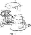
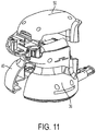
- the three housing parts 30, 40 and 50 can be seen throughout the drawings and are shown in exploded views in Figs. 10 and 11 .
- the housing parts 30, 40, 50 come together to form a battery receptacle portion 60.
- the battery receptacle portion 60 receives a removable battery pack 100 which powers the sander 10.
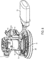
- a motor 80 rotates an output shaft 81 which rotates a fan 83 and the sanding platen 200.
- a bearing 82 supports the output shaft 81.
- the platen 200 receives the output shaft 81 in an eccentric manner so that the platen 200 moves in an orbital motion when driven by the motor 80.
- the battery receptacle portion 60 includes a first rail 42 and a second rail 51. It also includes an electrical connection section 62 which includes a number of electrical connectors 63. The electrical connectors 63 engage electrical connectors from the battery pack 100 so that the pack 100 can provide power to the motor 80.
- the first rail 42 is made up of a rail section 31 from the first housing part 30 and a rail section 41 from the second housing part 40.
- the second rail 51 is formed from the top housing part 50. As seen, the rails 42 and 51 are generally perpendicular to a rotational axis of the motor 80. They also run horizontally when the sander 10 is placed on a flat horizontal surface. Additionally, the electrical connector section 62 is sandwiched between the second housing part 40 and the top housing part 50.
- the three part construction of the sander housing 20 allows for an efficient design, assembly and for construction of the rails 42 and 51.
- various parts such as the motor 80 can be inserted into the second housing part 40.
- the first housing part 30 and the second housing part 40 are connected to one another to secure the motor 80 therebetween.
- Bringing the first housing part 30 and the second housing part 40 together forms the first rail 42 out of the rail section 31 from the first housing part 30 and the rail section 41 from the second housing part 40.
- the electrical connector section 62 is inserted into the second housing part 40 at the slot 65 shown in Fig. 7.
- Fig. 7 shows the housing parts 30 and 40 without the electrical connector section 62, which allows the slot 65 to be seen.
- the top housing part 50 is then connected to the first and second housing parts 30, 40 to provide the second rail 51 and to secure the electrical connector 62.
- one or more of the motor 80, bearing 82, fan 83 and other parts may be inserted into the first housing part 30 instead of the second housing part 40 so long as they can be clamped between the two housing parts 30, 40.
- the electrical connector section 62 may be inserted before or after the first housing part 30 and the second housing part 40 are connected.
- the three-part housing construction of the exemplary embodiment may have several advantages. For example, clamping operations in more than one direction can be performed. That is, the motor 80 can be held between the first and second housing sections 30, 40. Due to its location and the construction of the housing 20, the electrical connection section 62 cannot is not clamped between the first and second housing sections 30, 40. However, the electrical connection section 62 can be held between the second housing section 40 and the top housing section 50. Particularly, the electrical connection section 62 can be inserted into the second housing part 40 from a vertical direction. The top housing section 50 can then be assembled onto the first and second housing parts 30, 40 from the vertical direction to hold the electrical connection section 62 in place.
- the exemplary embodiment of the present application allows for multiple clamping or holding operations between housing parts to take place.
- the motor 80 can be held between the first and second housing parts 30, 40 in a first operation in a first direction and the electrical connection section 62 can be held between the top housing part 50 and the second housing part.
- Fig. 12 is a perspective view of the pack 100.
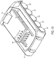
- Fig. 13 is a perspective view of the pack 100 with a lower part of the pack housing 201 removed.
- Fig. 14 is a side view of the pack 100 with a lower part of the pack housing 201 removed.
- Fig. 15 is a top view of the pack 100 with the pack housing 201 removed.
- the power tool battery pack 100 includes a set of rechargeable battery cells 220 disposed in a housing 201.
- the housing 201 includes guide rails 104 for engaging the rails 42 and 51 of the sander housing 20.
- the rails 104 slide between the rails 42, 51 and the rest of the sander housing 20 and the rails 42, 51 guide the battery pack 100 into place and prevent it from moving away from the motor 80 area of the housing 20.
- the battery pack 100 includes a latch 105 for securing the battery pack 100 in place.
- the latch 105 is biased upwardly by a spring (not shown) and the latch 105 can be moved by depression of the latch actuator 106, which may be integral with the latch 105.
- the battery pack 100 also includes a connection section 103 through which the battery pack 100 can make connection with the sander 10.
- the connection section includes four openings 111, 112, 113 and 114.
- Figs. 13-15 each have at least part of the battery pack housing 201 removed.
- the pack 100 includes a plurality of rechargeable battery cells 220.
- a cradle 16 ( Fig. 14 ) sits over the battery cells 220 and a printed circuit board (PCB) 140 ( Fig. 15 ) is connected to the cradle 16.
- the PCB 140 is in electrical connection with the battery cells 220.
- Electric connectors 121, 122, 123 and 124 are mounted on the PCB 140 and connect with power tools through the connection section 103, specifically openings 111, 112, 113 and 114 shown in Fig. 12 .
- the electrical connecters serve as terminals for the battery pack 100.
- Connector 121 may serve as a negative terminal; connector 122 may be a temperature terminal which relays information related to a temperature of the battery pack; connector 123 may be an ID terminal which relays information related to identifying the pack and connector 124 may be a positive terminal.
- the battery pack 100 electrically connects with the sander 10 at the battery pack electrical connector section 62.
- the electrical connector section 62 includes three electrical connectors 63.
- the electrical connectors 63 connect with the positive, negative and temperature terminals 121, 124 and 122 of the battery pack 10.
- the ID terminal 123 of the battery pack 100 is used when charging the battery pack 100.
- the battery pack 100 may be charged by a separate battery pack charger (not shown).
Landscapes
- Engineering & Computer Science (AREA)
- Mechanical Engineering (AREA)
- Chemical & Material Sciences (AREA)
- Chemical Kinetics & Catalysis (AREA)
- Electrochemistry (AREA)
- General Chemical & Material Sciences (AREA)
- Finish Polishing, Edge Sharpening, And Grinding By Specific Grinding Devices (AREA)
- Battery Mounting, Suspending (AREA)
Abstract
A power tool includes a housing. A motor is housed in the housing. A platen is driven by the motor. The housing includes a first housing part, a second housing part and a third housing part. The housing defines a battery receptacle portion configured to receive a removable battery pack which powers the motor. Each of the first housing part, the second housing part and the third housing part forms part of the battery receptacle portion.
Description
- The present invention relates to power tools.
- There are various existing power tools. It is desired to provide a power tool with an efficient housing construction.
- A first aspect of the present invention provides a power tool according to Claim 1.
- Preferred and other optional features of the invention are described and defined in the dependent claims.
- According to an aspect of the invention, there is provided a power tool which includes a housing. A motor is housed in the housing. A platen is driven by the motor. The housing includes a first housing part, a second housing part and a third housing part. The housing defines a battery receptacle portion configured to receive a removable battery pack which powers the motor. Each of the first housing part, the second housing part and the third housing part form part of the battery receptacle portion.
- The battery receptacle portion may include a first rail and a second rail, the first and second rails are configured to engage rails of the removable battery pack.
- The first, second and third housing parts may each form part of at least one of the first rail and the second rail.
- The first housing part and the second housing part may together form the first rail.
- The third housing part may form the second rail.
- The first housing part may be a first side housing part. The second housing part may be a second side housing part. The third housing part may be a top housing part.
- The first side housing part and the second side housing parts may form sides of the housing when the platen is disposed on a flat horizontal surface and the top housing part forms a top part of the housing when the platen is disposed on a flat horizontal surface.
- The power tool may be a sander.
- The first rail may be generally perpendicular to a rotational axis of the motor.
- An electrical connector may be configured to electrically engage with the battery pack is held between the second housing part and the third housing part.
- According to another aspect of the invention, there is provided a sander including a housing, a motor housed in the housing, and a sanding platen which is driven by the motor. The housing includes a first housing part, a second housing part and a third housing part. The housing defines a battery receptacle portion configured to receive a removable battery pack which powers the motor, the battery receptacle portion including a first rail and a second rail, the first rail and the second rail configured to engage rails of the removable battery pack. The first rail is comprised of the first housing part and the second housing part.
- The second rail may be comprised of the third housing part.
- The sander may further include an electrical connector held between the second housing part and the third housing part.
- The first housing part may be a first side housing part. The second housing part may be a second side housing part. The third housing part may be a top housing part.
- The first side housing part and the second side housing parts may form sides of the housing when the platen is disposed on a flat horizontal surface and the top housing part forms a top part of the housing when the platen is disposed on a flat horizontal surface.
- The first rail and the second rail may be generally perpendicular to a rotational axis of the motor.
- The first housing part, the second housing part and the third housing part may be made of a plastic material.
- According to another aspect of the invention, there is provided a power tool including a housing, a motor housed in the housing, and a platen which is driven by the motor. The housing includes a first housing part, a second housing part and a third housing part. The housing defines a battery receptacle portion configured to receive a removable battery pack which powers the motor, the battery receptacle portion comprising a first rail and a second rail, the first rail and the second rail configured to engage rails of the removable battery pack. The third housing part is a top housing part that forms a top part of the housing when the platen is disposed on a flat horizontal surface. The second rail is comprised of the third housing part.
- The first rail may be comprised of the first housing part and the second housing part.
- The sander may further include an electrical connector held between the second housing part and the third housing part.
- The first housing part may be a first side housing part. The second housing part may be a second side housing part. The first side housing part and the second side housing parts may form sides of the housing when the platen is disposed on a flat horizontal surface.
- The power tool may be a sander.
- According to another aspect of the invention, there is provided a method of constructing a power tool. The method includes providing a first housing part, a second housing part and a third housing part. Moving the first housing part and the second housing part relatively toward each other to capture a motor therebetween and assembling the first housing part and the second housing part together. Moving the third housing part relatively towards the assembled first and second housing parts to capture a connector component therebetween.
- The first housing part, the second housing part and the third housing part may be comprised of plastic.
- The connector component may be an electrical connector component.
- The electrical connector component may be configured to engage with a battery pack to power the power tool.
- The first housing part may include a first side part which forms a first side of the power tool when the power tool is placed on a flat horizontal surface.
- The second housing part may include a second side part which form a second side of the power tool when the power tool is placed on the flat horizontal surface.The third housing part may include a top part which forms a top of the power tool when the power tool is placed on the flat horizontal surface.
- The first housing part and the second housing part may each form part of a first rail configured to engage a first rail of the battery pack.
- The third housing part may form a second rail configured to engage a second rail of the battery pack.
- It is to be understood that any feature, including any preferred feature, of any aspect of the invention may be a feature, including a preferred feature, of any other aspect of the invention.
- Embodiments of the invention will now be described, by way of example, with reference to the accompanying drawings, of which:
-
Fig. 1 is a perspective view of an exemplary embodiment of a sander according to the invention; -
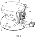
Fig 2 is another perspective view of the exemplary embodiment of the sander; -
Fig. 3 is a perspective view of the housing of the exemplary embodiment of the sander; -
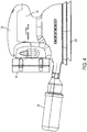
Fig. 4 is a side view of the exemplary embodiment of the sander; -
Fig. 5 is another perspective view of the exemplary embodiment of the sander with the battery pack removed; -
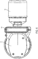
Fig. 6 is a top view of the exemplary embodiment of the sander; -
Fig. 7 is a perspective view of the first and second housing parts of the exemplary embodiment of the sander; -
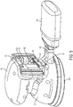
Fig. 8 is a perspective view of the exemplary embodiment of the sander with first and third housing parts removed illustrating internal parts of the sander; -
Fig. 9 is a side view of the exemplary embodiment of the sander with first and third housing parts removed illustrating internal parts of the sander; -
Fig. 10 is an exploded perspective view of the housing of the exemplary embodiment of the sander; -
Fig. 11 is another exploded perspective view of the housing of the exemplary embodiment of the sander; -
Fig. 12 is a perspective view of an exemplary embodiment of the battery pack; -
Fig. 13 is a perspective view of the exemplary embodiment of the battery pack with part of the battery pack housing removed to illustrate the battery cells; -
Fig. 14 is a side view of the exemplary embodiment of the battery pack with part of the battery pack housing removed to illustrate the battery cells; and -
Fig. 15 is a top view of the exemplary embodiment of the battery pack the battery pack housing removed. - An exemplary embodiment of the invention is shown in
Figs. 1-15 . The exemplary embodiment illustrates a power tool, in particular, a cordless random orbit sander (ROS) 10. Thesander 10 of the exemplary embodiment is a random orbit sander. Thesander 10 is powered by a removable andrechargeable battery pack 100. Thesander 10 is turned on and off by aswitch 11. As is well known, thesander 10 rotates aplaten 200 in a random orbit to remove materials. Thesander 10 of the present exemplary embodiment is a random orbit sander, but in other exemplary embodiments the sander could be a different type of sander, such as an orbit sander, a detail sander or a quarter-sheet sander. As shown, thesander 10 further includes adust chute 130 which directs dust into adust bag 135 for collection. - The
housing 20 of thesander 10 is comprised of three housing parts including a first housing part/first side part 30, a second housing part/second side part 40 and a third housing part/top housing part 50. The three housing parts are each made of plastic and are assembled together by screws. The threehousing parts Figs. 10 and11 . Thehousing parts battery receptacle portion 60. As will be appreciated, thebattery receptacle portion 60 receives aremovable battery pack 100 which powers thesander 10. - Internals of the sander are shown in
Figs. 8 and9 , in which thefirst side part 30 and thetop housing part 50 have been removed. As shown inFigs. 8 and9 , amotor 80 rotates anoutput shaft 81 which rotates afan 83 and the sandingplaten 200. Abearing 82 supports theoutput shaft 81. Theplaten 200 receives theoutput shaft 81 in an eccentric manner so that theplaten 200 moves in an orbital motion when driven by themotor 80. - As shown in
Fig. 5 , thebattery receptacle portion 60 includes afirst rail 42 and asecond rail 51. It also includes anelectrical connection section 62 which includes a number ofelectrical connectors 63. Theelectrical connectors 63 engage electrical connectors from thebattery pack 100 so that thepack 100 can provide power to themotor 80. Thefirst rail 42 is made up of arail section 31 from thefirst housing part 30 and arail section 41 from thesecond housing part 40. Thesecond rail 51 is formed from thetop housing part 50. As seen, therails motor 80. They also run horizontally when thesander 10 is placed on a flat horizontal surface. Additionally, theelectrical connector section 62 is sandwiched between thesecond housing part 40 and thetop housing part 50. - The three part construction of the
sander housing 20 allows for an efficient design, assembly and for construction of therails sander 20, various parts such as themotor 80 can be inserted into thesecond housing part 40. After that, thefirst housing part 30 and thesecond housing part 40 are connected to one another to secure themotor 80 therebetween. Bringing thefirst housing part 30 and thesecond housing part 40 together forms thefirst rail 42 out of therail section 31 from thefirst housing part 30 and therail section 41 from thesecond housing part 40. Theelectrical connector section 62 is inserted into thesecond housing part 40 at theslot 65 shown inFig. 7. Fig. 7 shows thehousing parts electrical connector section 62, which allows theslot 65 to be seen. After theelectrical connector section 62 is inserted into theslot 65, thetop housing part 50 is then connected to the first andsecond housing parts second rail 51 and to secure theelectrical connector 62. - Some of the above steps may be done in various orders or configurations. For example, one or more of the
motor 80, bearing 82,fan 83 and other parts may be inserted into thefirst housing part 30 instead of thesecond housing part 40 so long as they can be clamped between the twohousing parts electrical connector section 62 may be inserted before or after thefirst housing part 30 and thesecond housing part 40 are connected. - The three-part housing construction of the exemplary embodiment may have several advantages. For example, clamping operations in more than one direction can be performed. That is, the
motor 80 can be held between the first andsecond housing sections housing 20, theelectrical connection section 62 cannot is not clamped between the first andsecond housing sections electrical connection section 62 can be held between thesecond housing section 40 and thetop housing section 50. Particularly, theelectrical connection section 62 can be inserted into thesecond housing part 40 from a vertical direction. Thetop housing section 50 can then be assembled onto the first andsecond housing parts electrical connection section 62 in place. - As will be appreciated, the exemplary embodiment of the present application allows for multiple clamping or holding operations between housing parts to take place. For example, the
motor 80 can be held between the first andsecond housing parts electrical connection section 62 can be held between thetop housing part 50 and the second housing part. - The
battery pack 100 for powering thesander 10 is shown in further detail inFigs. 12-15 .Fig. 12 is a perspective view of thepack 100.Fig. 13 is a perspective view of thepack 100 with a lower part of thepack housing 201 removed.Fig. 14 is a side view of thepack 100 with a lower part of thepack housing 201 removed.Fig. 15 is a top view of thepack 100 with thepack housing 201 removed. - The power
tool battery pack 100 includes a set ofrechargeable battery cells 220 disposed in ahousing 201. Thehousing 201 includesguide rails 104 for engaging therails sander housing 20. Therails 104 slide between therails sander housing 20 and therails battery pack 100 into place and prevent it from moving away from themotor 80 area of thehousing 20. Thebattery pack 100 includes alatch 105 for securing thebattery pack 100 in place. Thelatch 105 is biased upwardly by a spring (not shown) and thelatch 105 can be moved by depression of thelatch actuator 106, which may be integral with thelatch 105. A battery pack with guide rails such as those shown these figures is more fully shown and described inUS Patent No. 6,729,413 , which is incorporated herein by reference in its entirety. Thebattery pack 100 also includes aconnection section 103 through which thebattery pack 100 can make connection with thesander 10. The connection section includes fouropenings -
Figs. 13-15 each have at least part of thebattery pack housing 201 removed. As shown, thepack 100 includes a plurality ofrechargeable battery cells 220. A cradle 16 (Fig. 14 ) sits over thebattery cells 220 and a printed circuit board (PCB) 140 (Fig. 15 ) is connected to thecradle 16. The PCB 140 is in electrical connection with thebattery cells 220. Electric connectors 121, 122, 123 and 124 are mounted on the PCB 140 and connect with power tools through theconnection section 103, specificallyopenings Fig. 12 . The electrical connecters serve as terminals for thebattery pack 100. Connector 121 may serve as a negative terminal; connector 122 may be a temperature terminal which relays information related to a temperature of the battery pack; connector 123 may be an ID terminal which relays information related to identifying the pack and connector 124 may be a positive terminal. - The
battery pack 100 electrically connects with thesander 10 at the battery packelectrical connector section 62. Theelectrical connector section 62 includes threeelectrical connectors 63. Theelectrical connectors 63 connect with the positive, negative and temperature terminals 121, 124 and 122 of thebattery pack 10. The ID terminal 123 of thebattery pack 100 is used when charging thebattery pack 100. Thebattery pack 100 may be charged by a separate battery pack charger (not shown). - While the invention has been described by way of exemplary embodiments, it is understood that the words which have been used herein are words of description, rather than words of limitation. Changes may be made within the purview of the appended claims, without departing from the scope of the invention.
Claims (14)
- A power tool comprising:a housing;a motor housed in the housing;a platen which is driven by the motor;wherein the housing comprises a first housing part, a second housing part and a third housing part;wherein the housing defines a battery receptacle portion configured to receive a removable battery pack which powers the motor in use; andwherein each of the first housing part, the second housing part and the third housing part forms part of the battery receptacle portion.
- The power tool of claim 1, wherein the battery receptacle portion comprises a first rail and a second rail, the first and second rails configured to engage rails of the removable battery pack.
- The power tool of claim 2, wherein the first, second and third housing parts each form part of at least one of the first rail and the second rail.
- The power tool of claim 2 or claim 3, wherein the first housing part and the second housing part together form the first rail.
- The power tool of any one of claims 2 to 4, wherein the third housing part forms the second rail.
- The power tool of Claim 5, wherein only the third housing part, and not either of the first and second housing parts, forms the second rail.
- The power tool of Claim 5 or Claim 6, wherein the third housing part does not form any part of the first rail.
- The power tool of any preceding claim, wherein the first housing part is a first side housing part, wherein the second housing part is a second side housing part, and wherein the third housing part is a top housing part.
- The power tool of Claim 8, wherein the first side housing part and the second side housing part each form sides of the housing, and the top housing part forms a top part of the housing, when the platen is disposed on a flat horizontal surface.
- The power tool of Claim 2 or any claim dependent thereon, wherein the first and second rails are generally perpendicular to a rotational axis of the motor.
- The power tool of any preceding claim, wherein an electrical connector configured to electrically engage with the battery pack is held between the second housing part and the third housing part.
- The power tool of any preceding claim, wherein the first housing part, the second housing part and the third housing part each comprise a plastic material.
- The power tool of any preceding claim, further comprising the battery pack.
- The power tool of any preceding claim, wherein the power tool is a sander.
Applications Claiming Priority (1)
| Application Number | Priority Date | Filing Date | Title |
|---|---|---|---|
| US15/249,818 US10632589B2 (en) | 2016-08-29 | 2016-08-29 | Power tool |
Publications (1)
| Publication Number | Publication Date |
|---|---|
| EP3315264A1 true EP3315264A1 (en) | 2018-05-02 |
Family
ID=59713841
Family Applications (1)
| Application Number | Title | Priority Date | Filing Date |
|---|---|---|---|
| EP17187441.5A Withdrawn EP3315264A1 (en) | 2016-08-29 | 2017-08-23 | Power tool |
Country Status (3)
| Country | Link |
|---|---|
| US (5) | US10632589B2 (en) |
| EP (1) | EP3315264A1 (en) |
| CN (1) | CN207971792U (en) |
Cited By (3)
| Publication number | Priority date | Publication date | Assignee | Title |
|---|---|---|---|---|
| EP3988245A1 (en) * | 2020-10-20 | 2022-04-27 | Robert Bosch GmbH | Manual grinding machine and method for installing same |
| EP4059400A1 (en) * | 2021-03-16 | 2022-09-21 | Black & Decker, Inc. | Powered sander with dust collection feature |
| US20230339092A1 (en) * | 2019-08-08 | 2023-10-26 | Black & Decker Inc. | Power tools and power tools platform |
Families Citing this family (14)
| Publication number | Priority date | Publication date | Assignee | Title |
|---|---|---|---|---|
| US10632589B2 (en) | 2016-08-29 | 2020-04-28 | Black & Decker Inc. | Power tool |
| CN108527092B (en) * | 2017-03-06 | 2021-06-18 | 南京德朔实业有限公司 | Two-handed sander |
| USD884447S1 (en) | 2018-04-19 | 2020-05-19 | Black & Decker Inc. | Sander |
| JP7099535B2 (en) * | 2018-09-28 | 2022-07-12 | 工機ホールディングス株式会社 | Working machine |
| DE102019006574A1 (en) * | 2019-09-18 | 2021-03-18 | Metabowerke Gmbh | Hand machine tool and method of making a hand machine tool |
| JP7497236B2 (en) * | 2020-07-13 | 2024-06-10 | 株式会社マキタ | Portable Polishing Machine |
| TWI753530B (en) * | 2020-08-13 | 2022-01-21 | 鼎朋企業股份有限公司 | Electric Grinding Tool Machine |
| EP3964330A1 (en) | 2020-09-04 | 2022-03-09 | X'Pole Precision Tools Inc. | Electric grinding machine tool |
| US20220072676A1 (en) * | 2020-09-04 | 2022-03-10 | X'pole Precision Tools Inc. | Electric grinding machine tool |
| US11728538B2 (en) | 2020-09-23 | 2023-08-15 | Techtronic Cordless Gp | Power tool battery pack receptacle |
| CN221020359U (en) * | 2020-11-18 | 2024-05-28 | 米沃奇电动工具公司 | Rail type sander |
| US20230017671A1 (en) * | 2021-07-14 | 2023-01-19 | Milwaukee Electric Tool Corporation | Quarter sheet sander |
| CN115958502A (en) * | 2021-10-13 | 2023-04-14 | 南京泉峰科技有限公司 | Sander and airflow chip removal device suitable for electric tool |
| CN115446706B (en) * | 2022-08-29 | 2024-04-23 | 浙江明磊锂能源科技股份有限公司 | Electric tool |
Citations (6)
| Publication number | Priority date | Publication date | Assignee | Title |
|---|---|---|---|---|
| US20030121676A1 (en) * | 2001-12-27 | 2003-07-03 | Ortt Earl M. | Combined fastenerless motor end cap and output device mounting |
| US6729413B2 (en) | 2001-08-24 | 2004-05-04 | Black & Decker Inc. | Power tool with battery pack ejector |
| US20080122403A1 (en) * | 2006-11-03 | 2008-05-29 | Snap-On Incorporated | Kit of power tools |
| US7476144B2 (en) * | 2007-06-13 | 2009-01-13 | Black & Decker Inc. | Sander |
| US20110147031A1 (en) * | 2008-07-02 | 2011-06-23 | Robert Bosch Gmbh | Electric machine tool |
| US20140008090A1 (en) * | 2011-03-31 | 2014-01-09 | Ingersoll-Rand Company | Handheld Power Tools with Triggers and Methods for Assembling Same |
Family Cites Families (127)
| Publication number | Priority date | Publication date | Assignee | Title |
|---|---|---|---|---|
| GB1340656A (en) | 1972-06-07 | 1973-12-12 | Yuen Se Kit | Cordless polisher |
| US4005502A (en) | 1975-09-25 | 1977-02-01 | Stevens Boyer Elaine | Electric power scrubber |
| US4447749A (en) | 1981-07-29 | 1984-05-08 | Black & Decker Inc. | Cordless electric device having contact increasing means |
| JPS58222802A (en) | 1982-06-21 | 1983-12-24 | 松下電工株式会社 | Electric type circular saw |
| JPS6161761A (en) | 1984-08-29 | 1986-03-29 | Makita Denki Seisakusho:Kk | Cordless polishing machine |
| DE3503024A1 (en) | 1985-01-30 | 1986-07-31 | Kress-elektrik GmbH & Co, Elektromotorenfabrik, 7457 Bisingen | ELECTRICAL HAND TOOL |
| US4847513A (en) | 1988-02-26 | 1989-07-11 | Black & Decker Inc. | Power-operated device with a cooling facility |
| US5018314A (en) | 1989-06-08 | 1991-05-28 | Makita Electric Works, Ltd. | Sander |
| GB9115603D0 (en) | 1991-07-19 | 1991-09-04 | Black & Decker Inc | Improvements in electrical arrangements in power tools and switches |
| GB9123502D0 (en) | 1991-11-06 | 1992-01-02 | Black & Decker Inc | Sanding apparatus |
| USD347778S (en) | 1993-01-22 | 1994-06-14 | Porter-Cable Corporation | Sander |
| US5384984A (en) | 1993-01-22 | 1995-01-31 | Porter-Cable Corporation | Random orbit sander with brake |
| US5392568A (en) | 1993-12-22 | 1995-02-28 | Black & Decker Inc. | Random orbit sander having braking member |
| GB9415011D0 (en) | 1994-07-26 | 1994-09-14 | Black & Decker Inc | Improved oscillating hand tool |
| GB9423848D0 (en) | 1994-11-25 | 1995-01-11 | Black & Decker Inc | Improved oscillating hand tool |
| DE19510291C2 (en) | 1995-03-22 | 1998-09-24 | Bosch Gmbh Robert | Hand tool with braking device |
| US5551114A (en) | 1995-06-20 | 1996-09-03 | Lee; Tao-Pan | Shoeshine assembly |
| US5595531A (en) | 1995-07-26 | 1997-01-21 | Ryobi North America | Random orbit sander having speed limiter |
| USD380950S (en) | 1996-01-22 | 1997-07-15 | Black & Decker Inc. | Polisher housing |
| JP3316622B2 (en) | 1996-03-08 | 2002-08-19 | 株式会社マキタ | Sanda |
| US5956792A (en) | 1996-04-29 | 1999-09-28 | Black & Decker, Inc. | Hand held motorized cleaning apparatus with linear, orbital and/or dual motion |
| US5706541A (en) | 1996-04-29 | 1998-01-13 | Black & Decker Inc. | Watertight friction fit battery cap with cam removal |
| US5718014A (en) | 1996-04-29 | 1998-02-17 | Black & Decker Inc. | Hand held motorized tool with over-molded cover |
| US5978999A (en) | 1996-04-29 | 1999-11-09 | Black & Decker Inc. | Motorized scrub brush with multiple hand holding positions |
| US5697115A (en) | 1996-04-29 | 1997-12-16 | Black & Decker Inc. | Cleaning apparatus with triangular shaped mount for attachment and quick disconnect |
| DE19626731A1 (en) * | 1996-07-03 | 1998-01-08 | Wagner Gmbh J | Handwork tool, especially electric screwdriver |
| GB9802587D0 (en) | 1998-02-07 | 1998-04-01 | Black & Decker Inc | Power tool |
| US6213851B1 (en) | 1998-07-07 | 2001-04-10 | Delta International Machinery Corp. | Abrading apparatus |
| US6106690A (en) * | 1998-12-07 | 2000-08-22 | Reynolds Tech Fabricators, Inc. | Electroplaner |
| DE29900612U1 (en) | 1999-01-15 | 1999-03-18 | Chung, Lee-Hsin-Chih, Chung-Li, Taoyuan | Delay device for a grinding machine |
| DE19905085A1 (en) | 1999-01-29 | 2000-08-03 | Black & Decker Inc N D Ges D S | Battery operated, hand-held power tool |
| US6264539B1 (en) | 2000-01-12 | 2001-07-24 | Tony Chen | Mechanism for slowing down idling shoe of an electric polisher |
| GB0005897D0 (en) | 2000-03-10 | 2000-05-03 | Black & Decker Inc | Power tool |
| GB0005821D0 (en) | 2000-03-10 | 2000-05-03 | Black & Decker Inc | Coupling method |
| DE10031761A1 (en) | 2000-06-29 | 2002-01-10 | Bosch Gmbh Robert | Eccentric plate grinding machine has cylindrical housing, braking arrangement with through openings exposed and closed by valve-like flaps for ventilating suction chamber |
| USD447397S1 (en) | 2000-10-16 | 2001-09-04 | Black & Decker Inc. | Sander |
| DE10134308A1 (en) | 2001-07-14 | 2003-01-30 | Bosch Gmbh Robert | Hand tool |
| GB2380151B (en) | 2001-07-20 | 2004-09-22 | Black & Decker Inc | Oscillating hand tool |
| GB2377662B (en) | 2001-07-20 | 2004-09-22 | Black & Decker Inc | Oscillating hand tool |
| US6758731B2 (en) | 2001-08-10 | 2004-07-06 | One World Technologies Limited | Orbital sander |
| USD471329S1 (en) | 2002-01-31 | 2003-03-04 | Choon Nang Electrical Appliance Mfy., Ltd. | Electric cleaner/polisher |
| JP2005537890A (en) | 2002-09-11 | 2005-12-15 | ザ プロクター アンド ギャンブル カンパニー | Multi-operation stain brush |
| US7469703B2 (en) | 2002-09-11 | 2008-12-30 | The Procter & Gamble Company | Stain-removal brush |
| US7581323B2 (en) | 2002-09-17 | 2009-09-01 | Credo Technology Corporation | Cordless circular saw |
| US7313838B2 (en) | 2002-12-03 | 2008-01-01 | S.C. Johnson & Son, Inc. | Powered cleaner/polisher |
| US6955549B2 (en) * | 2003-05-28 | 2005-10-18 | One World Technologies Limited | Slide type battery ejection mechanism |
| CA2537584C (en) | 2003-09-03 | 2011-11-08 | The Procter & Gamble Company | Multi-surfaces cleaning implement |
| US7516508B2 (en) | 2003-09-03 | 2009-04-14 | The Procter & Gamble Company | Motorized cleaning implement |
| US7565712B2 (en) * | 2003-11-26 | 2009-07-28 | S.C. Johnson & Son, Inc. | Powered cleaner/polisher |
| GB2423492B (en) | 2003-12-22 | 2008-06-25 | Bosch Gmbh Robert | Hand-held machine tool |
| USD525752S1 (en) | 2004-02-13 | 2006-07-25 | Jinding Group Co., Ltd. | Polisher with handgrip |
| DE102004016015A1 (en) | 2004-04-01 | 2005-10-20 | Bosch Gmbh Robert | Hand-guided grinding machine, grinding machine holding unit and grinding machine housing |
| USD534323S1 (en) | 2004-06-18 | 2006-12-26 | Hong Liang-Ming | Cordless car polisher |
| ATE458589T1 (en) | 2004-07-02 | 2010-03-15 | Black & Decker Inc | POWER TOOL |
| EP1612001A1 (en) | 2004-07-02 | 2006-01-04 | BLACK & DECKER INC. | Handle assembly for power tool |
| USD538490S1 (en) | 2004-07-16 | 2007-03-13 | Hong Liang-Ming | Cordless car polisher |
| USD509722S1 (en) | 2004-07-20 | 2005-09-20 | Black & Decker Inc. | Sander |
| DE102004047811A1 (en) | 2004-09-29 | 2006-03-30 | Robert Bosch Gmbh | Grinding hand tool machine, in particular Akkuschleifhandwerkzeugmaschine |
| DE102004047808A1 (en) | 2004-09-29 | 2006-03-30 | Robert Bosch Gmbh | Grinding hand tool machine, in particular Akkuschleifhandwerkzeugmaschine |
| USD526868S1 (en) | 2004-11-23 | 2006-08-22 | Black & Decker Inc. | Sander |
| US7198559B2 (en) | 2004-12-23 | 2007-04-03 | Black & Decker, Inc. | Modular sander-casing architecture |
| EP1674205B1 (en) * | 2004-12-23 | 2014-03-19 | Black & Decker Inc. | Drive mechanism for power tool |
| USD528387S1 (en) | 2005-02-03 | 2006-09-19 | Black & Decker Inc. | Mouse sander |
| US7104873B1 (en) | 2005-04-18 | 2006-09-12 | Positec Power Tools (Suzhou) Co. | Anti-vibration arrangement |
| USD548901S1 (en) | 2005-06-03 | 2007-08-14 | Hong Liang-Ming | Cordless waxer with auto wax supply system |
| DE102005038088A1 (en) * | 2005-08-11 | 2007-02-15 | Hilti Ag | Connecting arrangement between main housing and handle housing |
| DE102005061870A1 (en) | 2005-12-23 | 2007-07-05 | Robert Bosch Gmbh | Electric-powered hand tool e.g. rotary sanding or polishing tool has two-part housing with one overlapping half linked to the other by vibration dampener |
| JP5316831B2 (en) * | 2006-02-28 | 2013-10-16 | 日立工機株式会社 | Cordless power tool or charger |
| SE0602364L (en) | 2006-11-08 | 2008-04-15 | Atlas Copco Tools Ab | Power tool with interchangeable gear unit |
| DE102006061634A1 (en) | 2006-12-27 | 2008-07-03 | Robert Bosch Gmbh | Eccentric grinder, has friction brake device with friction surface that stands perpendicularly to rotation axis of grinding disk that exhibits course, which is sloping outwards from inner side in radial direction |
| US8228029B2 (en) * | 2007-02-23 | 2012-07-24 | Milwaukee Electric Tool Corporation | Power tool, battery pack, and method of operating the same |
| US8151407B2 (en) * | 2007-03-09 | 2012-04-10 | G.B.D. Corp | Surface cleaning apparatus with enlarged dirt collection chamber |
| CN201061862Y (en) | 2007-06-25 | 2008-05-21 | 南京德朔实业有限公司 | An electric grinding tool |
| JP5680415B2 (en) * | 2007-10-10 | 2015-03-04 | プライム デイタム、インコーポレーテッド | Integrated fan drive system for cooling tower |
| JP5039574B2 (en) | 2008-01-11 | 2012-10-03 | リョービ株式会社 | Electric tool with battery |
| US8231437B2 (en) | 2008-03-03 | 2012-07-31 | Black & Decker Inc. | Low height quarter sheet sander |
| US8172650B2 (en) | 2008-03-18 | 2012-05-08 | Paul W. Huber | Automatic shift dual-action tool |
| CN201271828Y (en) | 2008-09-17 | 2009-07-15 | 南京德朔实业有限公司 | Sander |
| CN201295872Y (en) | 2008-11-12 | 2009-08-26 | 南京德朔实业有限公司 | Sander |
| DE102009012175A1 (en) | 2009-02-27 | 2010-09-02 | Andreas Stihl Ag & Co. Kg | Electrical appliance with a battery pack |
| US9186808B2 (en) | 2009-08-28 | 2015-11-17 | Makita Corporation | Power tool with continuously-variable transmission traction drive |
| JP5544143B2 (en) | 2009-11-04 | 2014-07-09 | リョービ株式会社 | Battery powered electric brush cutter |
| EP2674259B1 (en) | 2009-12-18 | 2017-11-01 | Techtronic Power Tools Technology Limited | Multi-function tool system |
| USD636244S1 (en) | 2009-12-21 | 2011-04-19 | Chevron Limited | Sander |
| WO2011110189A1 (en) | 2010-03-06 | 2011-09-15 | Husqvarna Ab | Battery driven electric tool |
| WO2012002860A1 (en) | 2010-07-02 | 2012-01-05 | Husqvarna Ab | Battery powered tool |
| US9224995B2 (en) | 2010-03-06 | 2015-12-29 | Husqvarna Ab | Battery powered tool and battery pack for a battery powered tool |
| DE102010039152A1 (en) | 2010-08-10 | 2012-02-16 | Robert Bosch Gmbh | Device for surface treatment, in particular grinding device, polishing device od. Like. |
| DE102010043182A1 (en) | 2010-10-29 | 2012-05-03 | Robert Bosch Gmbh | Portable machine tool |
| JP5503598B2 (en) | 2011-07-11 | 2014-05-28 | 住友ゴム工業株式会社 | Sidewall rubber composition and pneumatic tire |
| US20130020106A1 (en) | 2011-07-18 | 2013-01-24 | Black & Decker Inc. | Power tool |
| DE102011084432A1 (en) * | 2011-10-13 | 2013-04-18 | Robert Bosch Gmbh | Hand tool with mechanically controlled automatic on and off function |
| US9757806B2 (en) | 2011-10-20 | 2017-09-12 | Makita Corporation | Hand-held cutting tools |
| KR101593117B1 (en) | 2011-10-26 | 2016-02-11 | 케이테크 가부시키가이샤 | Grinding tool with eccentric rotation shaft |
| US9776315B2 (en) | 2011-11-11 | 2017-10-03 | Black & Decker Inc. | Power tool having interchangeable tool heads with an independent accessory switch |
| WO2013093619A2 (en) | 2011-12-19 | 2013-06-27 | Carine Elen | Motorized scrubbing, buffing, and polishing tool |
| JP5788782B2 (en) | 2011-12-21 | 2015-10-07 | 株式会社マキタ | Sanda |
| JP5841423B2 (en) | 2011-12-21 | 2016-01-13 | 株式会社マキタ | Sanda |
| EP2607016B1 (en) | 2011-12-21 | 2016-08-10 | Makita Corporation | Sander |
| CN102554882B (en) | 2012-02-28 | 2015-08-12 | 南京德朔实业有限公司 | Hand-held tool |
| JP5854896B2 (en) | 2012-03-12 | 2016-02-09 | 株式会社マキタ | Sanda |
| DE102012210893B4 (en) | 2012-06-26 | 2026-02-19 | Robert Bosch Gmbh | Hand grinder with a vibrating plate |
| JP6129668B2 (en) | 2012-09-26 | 2017-05-17 | 株式会社マキタ | Electric tool |
| JP2014079874A (en) | 2012-09-26 | 2014-05-08 | Makita Corp | Power tool |
| US9186788B2 (en) | 2012-11-15 | 2015-11-17 | Techtronic Power Tools Technology Limited | Lockout mechanism |
| USD703508S1 (en) | 2013-01-28 | 2014-04-29 | Makita Corporation | Portable electric circular saw |
| DE112013006575T5 (en) | 2013-02-01 | 2015-11-26 | Makita Corporation | cutting tool |
| JP6043195B2 (en) | 2013-02-01 | 2016-12-14 | 株式会社マキタ | Electric tool |
| JP2014148117A (en) | 2013-02-01 | 2014-08-21 | Makita Corp | Chain saw |
| US9630310B2 (en) | 2013-02-01 | 2017-04-25 | Makita Corporation | Electric tool |
| US20150328796A1 (en) | 2013-02-01 | 2015-11-19 | Makita Corporation | Cutting device |
| US20150328764A1 (en) | 2013-02-01 | 2015-11-19 | Makita Corporation | Power tool |
| US9555554B2 (en) | 2013-05-06 | 2017-01-31 | Milwaukee Electric Tool Corporation | Oscillating multi-tool system |
| US9956677B2 (en) | 2013-05-08 | 2018-05-01 | Black & Decker Inc. | Power tool with interchangeable power heads |
| DE102013217553B4 (en) * | 2013-09-03 | 2016-10-06 | Robert Bosch Gmbh | Grinding housing means |
| DE102013219450A1 (en) | 2013-09-26 | 2015-03-26 | Robert Bosch Gmbh | Battery operated eccentric sander with an electronically commutated electric motor |
| US10076833B2 (en) | 2013-10-10 | 2018-09-18 | Makita Corporation | Electric tools |
| DE102013225885A1 (en) | 2013-12-13 | 2015-06-18 | Robert Bosch Gmbh | Battery operated eccentric sander with a rechargeable battery |
| US9868199B2 (en) | 2014-01-29 | 2018-01-16 | Black & Decker Inc. | Paddle assembly on a compact sander |
| USD718998S1 (en) | 2014-01-29 | 2014-12-09 | Black & Decker Inc. | Electric hand-held sander |
| US10632589B2 (en) | 2016-08-29 | 2020-04-28 | Black & Decker Inc. | Power tool |
| JP7042570B2 (en) | 2017-08-09 | 2022-03-28 | 株式会社マキタ | Rechargeable polisher |
| USD884447S1 (en) | 2018-04-19 | 2020-05-19 | Black & Decker Inc. | Sander |
| CN212919153U (en) | 2020-06-29 | 2021-04-09 | 宁波汉浦工具有限公司 | Electric screwdriver |
| JP2022018201A (en) | 2020-07-15 | 2022-01-27 | 工機ホールディングス株式会社 | Electric tool |
| US12557903B2 (en) | 2021-08-18 | 2026-02-24 | Robert Bosch Gmbh | Interchangeable-tool machine interface for a cleaning brush |
| CN218836167U (en) | 2022-10-19 | 2023-04-11 | 宁波得力工具有限公司 | Electric hand drill shell and gear button mounting structure |
-
2016
- 2016-08-29 US US15/249,818 patent/US10632589B2/en active Active
-
2017
- 2017-08-23 EP EP17187441.5A patent/EP3315264A1/en not_active Withdrawn
- 2017-08-29 CN CN201721094183.3U patent/CN207971792U/en not_active Expired - Fee Related
-
2020
- 2020-03-30 US US16/833,853 patent/US11478892B2/en active Active
-
2022
- 2022-09-12 US US17/942,379 patent/US11858085B2/en active Active
- 2022-09-12 US US17/942,399 patent/US11958157B2/en active Active
-
2024
- 2024-03-22 US US18/613,603 patent/US20240227111A1/en active Pending
Patent Citations (6)
| Publication number | Priority date | Publication date | Assignee | Title |
|---|---|---|---|---|
| US6729413B2 (en) | 2001-08-24 | 2004-05-04 | Black & Decker Inc. | Power tool with battery pack ejector |
| US20030121676A1 (en) * | 2001-12-27 | 2003-07-03 | Ortt Earl M. | Combined fastenerless motor end cap and output device mounting |
| US20080122403A1 (en) * | 2006-11-03 | 2008-05-29 | Snap-On Incorporated | Kit of power tools |
| US7476144B2 (en) * | 2007-06-13 | 2009-01-13 | Black & Decker Inc. | Sander |
| US20110147031A1 (en) * | 2008-07-02 | 2011-06-23 | Robert Bosch Gmbh | Electric machine tool |
| US20140008090A1 (en) * | 2011-03-31 | 2014-01-09 | Ingersoll-Rand Company | Handheld Power Tools with Triggers and Methods for Assembling Same |
Cited By (5)
| Publication number | Priority date | Publication date | Assignee | Title |
|---|---|---|---|---|
| US20230339092A1 (en) * | 2019-08-08 | 2023-10-26 | Black & Decker Inc. | Power tools and power tools platform |
| US12202118B2 (en) | 2019-08-08 | 2025-01-21 | Black & Decker Inc. | Power tools and power tools platform |
| US12296455B2 (en) * | 2019-08-08 | 2025-05-13 | Black & Decker Inc. | Power tools and power tools platform |
| EP3988245A1 (en) * | 2020-10-20 | 2022-04-27 | Robert Bosch GmbH | Manual grinding machine and method for installing same |
| EP4059400A1 (en) * | 2021-03-16 | 2022-09-21 | Black & Decker, Inc. | Powered sander with dust collection feature |
Also Published As
| Publication number | Publication date |
|---|---|
| US20230001534A1 (en) | 2023-01-05 |
| US20180056473A1 (en) | 2018-03-01 |
| US11478892B2 (en) | 2022-10-25 |
| US20240227111A1 (en) | 2024-07-11 |
| US20200223026A1 (en) | 2020-07-16 |
| US11958157B2 (en) | 2024-04-16 |
| US11858085B2 (en) | 2024-01-02 |
| US10632589B2 (en) | 2020-04-28 |
| CN207971792U (en) | 2018-10-16 |
| US20230006299A1 (en) | 2023-01-05 |
Similar Documents
| Publication | Publication Date | Title |
|---|---|---|
| US11858085B2 (en) | Power tool | |
| CN209033767U (en) | A battery pack attachable to and supported by a power tool | |
| EP3067959A1 (en) | Battery pack comprising bushing for connecting end plate | |
| US9502801B2 (en) | Electric apparatus having a plate-shaped male terminal with a level difference in its thickness direction | |
| EP2909877B1 (en) | Battery pack with guide rails for improved terminal alignment | |
| US11677118B2 (en) | Battery cell module and battery pack | |
| US10511008B2 (en) | Battery contact with a surface texture | |
| KR20170047539A (en) | Battery pack | |
| WO2005038954A3 (en) | Power driver and charger with flexible mounting system for battery pack | |
| JPH1029172A (en) | Battery pack for rechargeable power tool and dummy battery for this battery pack | |
| US7710743B2 (en) | Remote ID resistor assembly for wiring harness | |
| EP2712713A1 (en) | Electronically driven mobile equipment comprising a battery pack and electronic power supply unit for use with such a mobile equipment | |
| CN101326703A (en) | Batteries for connection to electrical appliances | |
| US12506385B2 (en) | Power and home tools | |
| EP1781074A2 (en) | Diode assembly for a cordless power tool | |
| CN109964352B (en) | Apparatus for manufacturing battery pack | |
| EP4059400A1 (en) | Powered sander with dust collection feature | |
| JP5102545B2 (en) | Electronics | |
| KR100502721B1 (en) | Battery charger | |
| KR102187275B1 (en) | Battery module fixing pallet |
Legal Events
| Date | Code | Title | Description |
|---|---|---|---|
| PUAI | Public reference made under article 153(3) epc to a published international application that has entered the european phase |
Free format text: ORIGINAL CODE: 0009012 |
|
| STAA | Information on the status of an ep patent application or granted ep patent |
Free format text: STATUS: THE APPLICATION HAS BEEN PUBLISHED |
|
| AK | Designated contracting states |
Kind code of ref document: A1 Designated state(s): AL AT BE BG CH CY CZ DE DK EE ES FI FR GB GR HR HU IE IS IT LI LT LU LV MC MK MT NL NO PL PT RO RS SE SI SK SM TR |
|
| AX | Request for extension of the european patent |
Extension state: BA ME |
|
| STAA | Information on the status of an ep patent application or granted ep patent |
Free format text: STATUS: THE APPLICATION IS DEEMED TO BE WITHDRAWN |
|
| 18D | Application deemed to be withdrawn |
Effective date: 20181103 |