EP3315228B1 - Composant provenant de la fabrication additive pour une turbine a gaz - Google Patents
Composant provenant de la fabrication additive pour une turbine a gaz Download PDFInfo
- Publication number
- EP3315228B1 EP3315228B1 EP17198141.8A EP17198141A EP3315228B1 EP 3315228 B1 EP3315228 B1 EP 3315228B1 EP 17198141 A EP17198141 A EP 17198141A EP 3315228 B1 EP3315228 B1 EP 3315228B1
- Authority
- EP
- European Patent Office
- Prior art keywords
- metering
- feature
- component
- internal cooling
- metering feature
- Prior art date
- Legal status (The legal status is an assumption and is not a legal conclusion. Google has not performed a legal analysis and makes no representation as to the accuracy of the status listed.)
- Active
Links
- 238000001816 cooling Methods 0.000 claims description 53
- 238000004519 manufacturing process Methods 0.000 claims description 50
- 239000000463 material Substances 0.000 claims description 32
- 238000000034 method Methods 0.000 claims description 19
- 239000012530 fluid Substances 0.000 claims description 8
- 239000000654 additive Substances 0.000 description 21
- 230000000996 additive effect Effects 0.000 description 21
- 239000000843 powder Substances 0.000 description 13
- 239000002826 coolant Substances 0.000 description 7
- 238000005266 casting Methods 0.000 description 4
- 239000000155 melt Substances 0.000 description 4
- 238000002485 combustion reaction Methods 0.000 description 3
- 239000012809 cooling fluid Substances 0.000 description 3
- 239000012255 powdered metal Substances 0.000 description 3
- 238000007730 finishing process Methods 0.000 description 2
- 238000002844 melting Methods 0.000 description 2
- 230000008018 melting Effects 0.000 description 2
- 239000002184 metal Substances 0.000 description 2
- 239000012254 powdered material Substances 0.000 description 2
- 230000008646 thermal stress Effects 0.000 description 2
- 238000000149 argon plasma sintering Methods 0.000 description 1
- 238000000576 coating method Methods 0.000 description 1
- 238000005520 cutting process Methods 0.000 description 1
- 238000010894 electron beam technology Methods 0.000 description 1
- 239000000446 fuel Substances 0.000 description 1
- 230000008642 heat stress Effects 0.000 description 1
- 238000001513 hot isostatic pressing Methods 0.000 description 1
- 238000005495 investment casting Methods 0.000 description 1
- 238000003754 machining Methods 0.000 description 1
- 238000003801 milling Methods 0.000 description 1
- 239000000203 mixture Substances 0.000 description 1
- 238000012986 modification Methods 0.000 description 1
- 230000004048 modification Effects 0.000 description 1
- 238000005498 polishing Methods 0.000 description 1
- 238000007711 solidification Methods 0.000 description 1
- 230000008023 solidification Effects 0.000 description 1
- 238000005382 thermal cycling Methods 0.000 description 1
- 238000011144 upstream manufacturing Methods 0.000 description 1
- 238000007740 vapor deposition Methods 0.000 description 1
- 238000005406 washing Methods 0.000 description 1
Images


Classifications
-
- F—MECHANICAL ENGINEERING; LIGHTING; HEATING; WEAPONS; BLASTING
- F01—MACHINES OR ENGINES IN GENERAL; ENGINE PLANTS IN GENERAL; STEAM ENGINES
- F01D—NON-POSITIVE DISPLACEMENT MACHINES OR ENGINES, e.g. STEAM TURBINES
- F01D5/00—Blades; Blade-carrying members; Heating, heat-insulating, cooling or antivibration means on the blades or the members
- F01D5/12—Blades
- F01D5/14—Form or construction
- F01D5/18—Hollow blades, i.e. blades with cooling or heating channels or cavities; Heating, heat-insulating or cooling means on blades
- F01D5/187—Convection cooling
-
- B—PERFORMING OPERATIONS; TRANSPORTING
- B22—CASTING; POWDER METALLURGY
- B22F—WORKING METALLIC POWDER; MANUFACTURE OF ARTICLES FROM METALLIC POWDER; MAKING METALLIC POWDER; APPARATUS OR DEVICES SPECIALLY ADAPTED FOR METALLIC POWDER
- B22F10/00—Additive manufacturing of workpieces or articles from metallic powder
-
- B—PERFORMING OPERATIONS; TRANSPORTING
- B22—CASTING; POWDER METALLURGY
- B22F—WORKING METALLIC POWDER; MANUFACTURE OF ARTICLES FROM METALLIC POWDER; MAKING METALLIC POWDER; APPARATUS OR DEVICES SPECIALLY ADAPTED FOR METALLIC POWDER
- B22F5/00—Manufacture of workpieces or articles from metallic powder characterised by the special shape of the product
- B22F5/009—Manufacture of workpieces or articles from metallic powder characterised by the special shape of the product of turbine components other than turbine blades
-
- B—PERFORMING OPERATIONS; TRANSPORTING
- B22—CASTING; POWDER METALLURGY
- B22F—WORKING METALLIC POWDER; MANUFACTURE OF ARTICLES FROM METALLIC POWDER; MAKING METALLIC POWDER; APPARATUS OR DEVICES SPECIALLY ADAPTED FOR METALLIC POWDER
- B22F5/00—Manufacture of workpieces or articles from metallic powder characterised by the special shape of the product
- B22F5/04—Manufacture of workpieces or articles from metallic powder characterised by the special shape of the product of turbine blades
-
- B—PERFORMING OPERATIONS; TRANSPORTING
- B33—ADDITIVE MANUFACTURING TECHNOLOGY
- B33Y—ADDITIVE MANUFACTURING, i.e. MANUFACTURING OF THREE-DIMENSIONAL [3-D] OBJECTS BY ADDITIVE DEPOSITION, ADDITIVE AGGLOMERATION OR ADDITIVE LAYERING, e.g. BY 3-D PRINTING, STEREOLITHOGRAPHY OR SELECTIVE LASER SINTERING
- B33Y80/00—Products made by additive manufacturing
-
- F—MECHANICAL ENGINEERING; LIGHTING; HEATING; WEAPONS; BLASTING
- F01—MACHINES OR ENGINES IN GENERAL; ENGINE PLANTS IN GENERAL; STEAM ENGINES
- F01D—NON-POSITIVE DISPLACEMENT MACHINES OR ENGINES, e.g. STEAM TURBINES
- F01D5/00—Blades; Blade-carrying members; Heating, heat-insulating, cooling or antivibration means on the blades or the members
- F01D5/02—Blade-carrying members, e.g. rotors
- F01D5/08—Heating, heat-insulating or cooling means
- F01D5/081—Cooling fluid being directed on the side of the rotor disc or at the roots of the blades
-
- B—PERFORMING OPERATIONS; TRANSPORTING
- B22—CASTING; POWDER METALLURGY
- B22F—WORKING METALLIC POWDER; MANUFACTURE OF ARTICLES FROM METALLIC POWDER; MAKING METALLIC POWDER; APPARATUS OR DEVICES SPECIALLY ADAPTED FOR METALLIC POWDER
- B22F10/00—Additive manufacturing of workpieces or articles from metallic powder
- B22F10/20—Direct sintering or melting
- B22F10/28—Powder bed fusion, e.g. selective laser melting [SLM] or electron beam melting [EBM]
-
- B—PERFORMING OPERATIONS; TRANSPORTING
- B22—CASTING; POWDER METALLURGY
- B22F—WORKING METALLIC POWDER; MANUFACTURE OF ARTICLES FROM METALLIC POWDER; MAKING METALLIC POWDER; APPARATUS OR DEVICES SPECIALLY ADAPTED FOR METALLIC POWDER
- B22F10/00—Additive manufacturing of workpieces or articles from metallic powder
- B22F10/60—Treatment of workpieces or articles after build-up
-
- F—MECHANICAL ENGINEERING; LIGHTING; HEATING; WEAPONS; BLASTING
- F05—INDEXING SCHEMES RELATING TO ENGINES OR PUMPS IN VARIOUS SUBCLASSES OF CLASSES F01-F04
- F05D—INDEXING SCHEME FOR ASPECTS RELATING TO NON-POSITIVE-DISPLACEMENT MACHINES OR ENGINES, GAS-TURBINES OR JET-PROPULSION PLANTS
- F05D2220/00—Application
- F05D2220/30—Application in turbines
- F05D2220/32—Application in turbines in gas turbines
-
- F—MECHANICAL ENGINEERING; LIGHTING; HEATING; WEAPONS; BLASTING
- F05—INDEXING SCHEMES RELATING TO ENGINES OR PUMPS IN VARIOUS SUBCLASSES OF CLASSES F01-F04
- F05D—INDEXING SCHEME FOR ASPECTS RELATING TO NON-POSITIVE-DISPLACEMENT MACHINES OR ENGINES, GAS-TURBINES OR JET-PROPULSION PLANTS
- F05D2230/00—Manufacture
- F05D2230/20—Manufacture essentially without removing material
- F05D2230/22—Manufacture essentially without removing material by sintering
-
- F—MECHANICAL ENGINEERING; LIGHTING; HEATING; WEAPONS; BLASTING
- F05—INDEXING SCHEMES RELATING TO ENGINES OR PUMPS IN VARIOUS SUBCLASSES OF CLASSES F01-F04
- F05D—INDEXING SCHEME FOR ASPECTS RELATING TO NON-POSITIVE-DISPLACEMENT MACHINES OR ENGINES, GAS-TURBINES OR JET-PROPULSION PLANTS
- F05D2230/00—Manufacture
- F05D2230/30—Manufacture with deposition of material
- F05D2230/31—Layer deposition
-
- F—MECHANICAL ENGINEERING; LIGHTING; HEATING; WEAPONS; BLASTING
- F05—INDEXING SCHEMES RELATING TO ENGINES OR PUMPS IN VARIOUS SUBCLASSES OF CLASSES F01-F04
- F05D—INDEXING SCHEME FOR ASPECTS RELATING TO NON-POSITIVE-DISPLACEMENT MACHINES OR ENGINES, GAS-TURBINES OR JET-PROPULSION PLANTS
- F05D2250/00—Geometry
- F05D2250/70—Shape
- F05D2250/75—Shape given by its similarity to a letter, e.g. T-shaped
-
- F—MECHANICAL ENGINEERING; LIGHTING; HEATING; WEAPONS; BLASTING
- F05—INDEXING SCHEMES RELATING TO ENGINES OR PUMPS IN VARIOUS SUBCLASSES OF CLASSES F01-F04
- F05D—INDEXING SCHEME FOR ASPECTS RELATING TO NON-POSITIVE-DISPLACEMENT MACHINES OR ENGINES, GAS-TURBINES OR JET-PROPULSION PLANTS
- F05D2260/00—Function
- F05D2260/20—Heat transfer, e.g. cooling
- F05D2260/221—Improvement of heat transfer
- F05D2260/2212—Improvement of heat transfer by creating turbulence
-
- F—MECHANICAL ENGINEERING; LIGHTING; HEATING; WEAPONS; BLASTING
- F05—INDEXING SCHEMES RELATING TO ENGINES OR PUMPS IN VARIOUS SUBCLASSES OF CLASSES F01-F04
- F05D—INDEXING SCHEME FOR ASPECTS RELATING TO NON-POSITIVE-DISPLACEMENT MACHINES OR ENGINES, GAS-TURBINES OR JET-PROPULSION PLANTS
- F05D2260/00—Function
- F05D2260/20—Heat transfer, e.g. cooling
- F05D2260/221—Improvement of heat transfer
- F05D2260/2214—Improvement of heat transfer by increasing the heat transfer surface
- F05D2260/22141—Improvement of heat transfer by increasing the heat transfer surface using fins or ribs
-
- Y—GENERAL TAGGING OF NEW TECHNOLOGICAL DEVELOPMENTS; GENERAL TAGGING OF CROSS-SECTIONAL TECHNOLOGIES SPANNING OVER SEVERAL SECTIONS OF THE IPC; TECHNICAL SUBJECTS COVERED BY FORMER USPC CROSS-REFERENCE ART COLLECTIONS [XRACs] AND DIGESTS
- Y02—TECHNOLOGIES OR APPLICATIONS FOR MITIGATION OR ADAPTATION AGAINST CLIMATE CHANGE
- Y02P—CLIMATE CHANGE MITIGATION TECHNOLOGIES IN THE PRODUCTION OR PROCESSING OF GOODS
- Y02P10/00—Technologies related to metal processing
- Y02P10/25—Process efficiency
Definitions
- the present disclosure relates generally to additively manufactured gas powered turbine components, and more specifically to cooling passage features of the same.
- Gas turbine engines generally operate by compressing a gas in a compressor and providing the compressed gas to a combustor.
- the compressed gas is mixed with a fuel, and ignited generating high temperature combustion gasses.
- the high temperature combustion gasses are then expanded across a turbine section, driving the turbine section to rotate. Rotation of the turbine section, in turn, drives the compressor to rotate.
- the rotation of the turbine section further drives the rotation of a fan forward of the compressor.
- the high temperature combustion gasses expose the gaspath components to substantial amounts of thermal cycling and heat stress.
- the flowpath components are actively cooled.
- the active cooling is achieved via cooling passages internal to the flowpath component.
- Typical methods of manufacturing gaspath components include various methods of removing material from a starting blank of material to form a desired completed part shape and casting a desired completed part shape around an investment casting core. Such methods utilize cutting tools and casting cores to form holes, surfaces, passages, overall shapes and more.
- EP 1 717 416 A1 discloses a prior art gas path component as set forth in the preamble of claim 1.
- WO 2015/069466 A1 discloses a prior art cooled combustor floatwall panel.
- one or more metering components are connected to the completed part at the inlet of the internal cooling passages.
- the metering components meter the flow of coolant into the internal cooling passages.
- the invention provides a gaspath component as recited in claim 1.
- the body and the metering feature are comprised of the same material.
- the at least one turbulating feature is a plurality of trip strips.
- the at least one opening includes at least one geometric feature protruding into the opening.
- the at least one opening is tapered.
- the at least one internal cooling passage is a plurality of cooling passages, wherein a first subset of the cooling passages include the metering feature and a second subset of cooling passages are characterized by a lack of the metering feature.
- the metering feature is internal to the at least one internal cooling passage.
- the metering feature has a thickness parallel to an expected flow of fluid through the metering feature, and the thickness is at least 37 mils (0.94 mm).
- the metering feature has a thickness parallel to an expected flow of fluid through the metering feature, and the thickness is at most 8 mils (0.20 mm).
- the body and the metering feature are a single additively manufactured component.
- the invention provides a method of manufacturing a gaspath component as recited in claim 9.
- manufacturing a gaspath component simultaneously manufacturing the component body including the plurality of internal cooling passages, and manufacturing the at least one metering feature interior to one of the internal cooling passages further comprises manufacturing a plurality of turbulating features within the internal cooling passages, downstream of the metering feature.
- any of the above described exemplary methods of manufacturing a gaspath component simultaneously manufacturing the component body including the plurality of internal cooling passages, and manufacturing the at least one metering feature interior to one of the internal cooling passages comprises manufacturing the component body and the metering feature as a single unitary structure of a single material.
- any of the above described exemplary methods of manufacturing a gaspath component simultaneously manufacturing the component body including the plurality of internal cooling passages, and manufacturing the at least one metering feature interior to one of the internal cooling passages comprises manufacturing the component body of a first material and the metering feature of a second material, distinct from the first material, as a single unitary structure.
- An alternative manufacturing process to the above described casting and machining processes is an additive manufacturing process, such as electron beam melting (EBM) and direct metal laser sintering (DMLS).
- additive manufacturing utilizes a heat source such as a laser beam to melt layers of powdered metal to form the desired part configuration layer upon layer.
- the laser forms a melt pool in the powdered metal that solidifies.
- Another layer of powdered material is then spread over the formerly solidified part and melted to the previous melted layer to build a desired part geometry layer upon layer. Powdered material that is applied but not melted to become a portion of the part accumulates around and within the part.
- the powder material utilized in each iteration of the process is identical, resulting in a structure created of a uniform material.
- the powders applied at each iteration can be varied and include different material compositions, allowing the end part to be a single unitary structure with portions constructed of two or more distinct materials.
- FIG. 1 schematically illustrates an exemplary additive manufacturing machine 10 configured to create a gaspath component.
- the additive manufacturing machine 10 includes a work space 12 that supports an energy transmitting device 18 and a base plate 14 on which a part 40 is supported during fabrication.
- the energy-transmitting device 18 emits a laser beam 20 that melts material 30 deposited by a material applicator 28.
- the example material 30 is a metal powder that is applied in a layer over the base plate 14 and subsequent layers are applied to produce a desired configuration of the part 40.
- the laser beam 20 directs energy that melts the powder material in a configuration that forms the desired part dimensions.
- the additive manufacturing process utilizes material 30 that is applied in layers on top of the base plate 14. Selective portions of the layers are subsequently melted by the energy emitted from the laser beam 20. The energy focused on the top layer of the part 40 generates the desired heat to melt portions of the powdered metal. Conduction of heat through the solidified portions of the part and convection cooling to the ambient environment solidifies the melded portions to build and grow the part 40. The melting and solidification process is repeated layer by layer to build the part 40.
- the additive manufacturing machine 10 is controlled via a computer 50, or other similar controller, that is connected to the additive manufacturing machine 10.
- the computer 50 can be integrated into the additive manufacturing machine 10. In either case, a completed part specification is entered into the computer 50 and the computer 50 determines how to construct the part 40 based on the particular additive manufacturing process of the additive manufacturing machine 10.
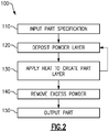
- Figure 2 schematically illustrates an exemplary process 100 utilized by the additive manufacturing machine 10 to generate a part 40.
- a user inputs the part specification into the computer 50 in an "Input Part Specification" step 110.
- the computer 50 determines the appropriate layers, and additive process to generate the desired part 40.
- the appropriate layers and process to generate the desired part 40 can be determined prior to inputting the specification, and the specification itself can include each of the desired layers.
- the additive manufacturing machine 10 deposits a layer of powder on the base plate 14 in a "Deposit Powder Layer" step 120.
- the material applicator 28 is configured to deposit only a single material, and every iteration of step 120 deposits the same material.
- the material applicator 28 can deposit multiple different materials, and each iteration can deposit the same or different materials from the previous iteration, depending on the needs of the specific process.
- the material applicator 28 can deposit different materials in different locations within a single iteration of the deposit powder layer step 120.
- the additive manufacturing machine 10 applies heat to the powder via the energy transmitting device 18 in an "Apply Heat to Create Part Layer" step 130.
- the heat melts the powder in a specific location adhering the layer to any previous layers, and causing the layer to be generated in the specific desired shape.
- Steps 120 and 130 are then iterated multiple times to create the desired three dimensional geometry of the part 40 being generated.
- the excess unmelted powder is removed from the part 40 in a "Remove Excess Powder” step 140.
- the excess powder can be removed using any conventional means including, but not limited to, vibrations, air pressure, washing and the like.
- the completed part is output in an "Output Part" step 150.
- the output part 150 can be further subjected to finishing processes such as polishing, application of additional coatings via vapor deposition and the like, or any other finishing process such as hot isostatic pressing, extrude hone, etc.
- gaspath components such as turbine blades, turbine vanes, blade outer air seals, and the like, are exposed to high temperature gasses during operation of a gas turbine engine. While illustrated herein with specific regards to an exemplary turbine blade, one of skill in the art having the benefit of this disclosure will understand that the disclosed concepts cover any gaspath component including internal cooling passages, and are not limited to the expressly illustrated example.
- internal cooling passages are included within the body of the gaspath component, and allow a cooling fluid to be passed through the gaspath component.
- cooling fluid such as air from a compressor bleed, is provided to an inlet of the internal cooling passage at a pressure greater than a desired pressure within the cooling passage.
- metering features are added to the gaspath component at the inlet of one or more internal cooling passages.
- the metering feature typically constitutes a plate having an opening. The plate is welded, or otherwise attached, to the gaspath component immediately upstream of the inlets. Attaching the metering feature post completion of the part requires additional manufacturing time and manufacturing expense, and can introduce additional failure points due to the attachment features.
- Figure 3 schematically illustrates an additively manufactured gaspath component 200 which, with regard to a single opening 252 in each of the metering features 250, falls outside the scope of the present invention, including a blade 210 extending outward from a platform 220. Extending opposite the blade 210, also from the platform 220, is a root 230. Within the gaspath component 200 are multiple internal cooling passages 240. In the illustrated example, the internal cooling passages 240 include inlets 242 at a radially inward portion of the root 230, relative to an installed position of the gaspath component 200. In alternative examples, the inlets 242 can be positioned anywhere on the root 230 or platform 220.
- each internal cooling passage 240 there are multiple turbulating features 244.
- the turbulating features 244 are trip strips.
- the turbulating features 244 can be any other surface feature configured to induce turbulence on the coolant flowing through the internal cooling passage 240.
- metering features 250 are metering plates that span the internal cooling passage 240 approximately normal to the expected direction of coolant flow through the cooling passage 240. In alternative examples, the metering feature 250 can be angled relative to the expected coolant flow and function in approximately the same manner.
- Each of the metering features 250 includes an opening 252 that allows fluid flow through the metering feature 250.
- the volume of fluid flow through the metering feature 250 is limited by the cross sectional area of the opening 252, or openings 252, thereby metering the flow of fluid into the internal cooling passage 240.
- a metering feature 250' can be positioned at the inlet 242 of the internal cooling passage 240 instead of downstream of a portion of the turbulating features 244, while still being interior to the internal cooling passage 240.
- the metering feature 250' does not extend beyond a base portion 232 of the root 230.
- the gaspath component 200 is constructed via an additive manufacturing process.
- the metering feature 250 is constructed internal to, and simultaneous with, the cooling passage 240, without extending beyond the base portion 232 of the root 230.
- the metering feature 250 is included downstream of one or more of the turbulating features 244. By including the metering feature 250 downstream of a portion of the turbulating features 244, desirable flow characteristics can be imparted on the cooling fluid prior to metering, as well as after the metering.
- Figures 4A-4C illustrate exemplary metering features 300A-C that can be included in the gaspath component 200 of Figure 3 as the metering feature 250.
- Each of the metering features 300A-C includes a plate portion 310 with a thickness 312 aligned with the expected direction of fluid flow through the metering feature 300A-C.
- Existing manufacturing methods where the metering plate is attached post completion of the gaspath component 200, are generally limited in the thickness of the metering plate that can be attached.
- the thickness in a typical metering plate for aerospace High Pressure Turbine Blades is limited to being between 9 and 36 mils (0.23 and 0.91 mm).
- the additive manufacturing process allows for a substantially wider range of thickness to be constructed, in addition to allowing the metering feature 250, 300 to be constructed internal to the cooling passage itself.
- the metering feature 250, 300 can be at most 8 mils thick (0.20 mm). In alternative examples, the metering feature 250, 300 can be in the range of 37-60 mils (0.94 - 1.52 mm).
- the metering features 300A-C include openings 320 that allow fluid to pass through the metering feature 300, 250 in a controlled volume.
- openings 320 that allow fluid to pass through the metering feature 300, 250 in a controlled volume.
- any number of distinct opening shapes and configurations can be utilized, including singular hole openings 320 falling outside the scope of the present invention (as in Figure 4A ), multiple evenly distributed openings 320 (as in Figure 4B ), and multiple unevenly distributed openings 320 (as in Figure 4C ).
- the unevenly distributed openings 320 can be concentrated in a single region 322 in order to increase the volume of coolant entering the cooling passage 240 in that region 322 relative to the coolant entering the cooling passage 240 outside of the region 322.
- the metering features 300A-C can include any, or all, of the above configurations within the cooling passages 240 themselves.
- the metering feature 300A includes multiple geometric features 330, 332 on the surface of the opening 320. While illustrated as included in the opening 320 of metering feature 300A, one of skill in the art, having the benefit of this disclosure, will understand that the geometric features 330, 320 can be applied to any metering feature 300A-C created using the process described herein.
- the geometric features 330, 332 operate to turbulate the coolant passing through the metering feature 300A, as it is passing through the opening 320.
- the downstream portion of the opening 320 can have a smaller surface area, resulting in a tapered opening 320.
- each of the metering features 250 is integral to the body of the gaspath component 200.
- the metering features 250, 300 are the same material as the body 200, and form a unitary structure.
- the metering features 250, 300 are a distinct material utilized during the additive manufacturing process.
- the distinct material is additively manufactured to be integral to, and a part of, the body 200.
Landscapes
- Engineering & Computer Science (AREA)
- Mechanical Engineering (AREA)
- Manufacturing & Machinery (AREA)
- General Engineering & Computer Science (AREA)
- Chemical & Material Sciences (AREA)
- Materials Engineering (AREA)
- Powder Metallurgy (AREA)
- Turbine Rotor Nozzle Sealing (AREA)
Claims (12)
- Composant de trajet de gaz (200) comprenant :un corps ayant au moins un passage de refroidissement interne (240) ; etun élément de mesure (300B ; 300C) solidaire audit passage de refroidissement interne (240), l'élément de mesure (300B ; 300C) et le corps étant une structure unitaire, dans lequel l'élément de mesure (300B ; 300C) comprend une plaque (310) recouvrant ledit passage de refroidissement interne (240) et la plaque (310) comporte une pluralité d'ouvertures (320) ; caractérisé en ce quel'au moins un passage de refroidissement interne (240) comporte au moins un élément de tourbillonnement (244) et l'élément de mesure (300B ; 300C) est en aval d'au moins l'un dudit au moins un élément de tourbillonnement (244).
- Composant de trajet de gaz (200) selon la revendication 1, dans lequel le corps et l'élément de mesure (300B ; 300C) sont composés du même matériau.
- Composant de trajet de gaz (200) selon la revendication 1 ou 2, dans lequel l'au moins un élément de tourbillonnement (244) est une pluralité de bandes de déclenchement.
- Composant de trajet de gaz (200) selon une quelconque revendication précédente, dans lequel les ouvertures (320) comportent au moins un élément géométrique (330, 332) faisant saillie dans lesdites ouvertures (320).
- Composant de trajet de gaz (200) selon une quelconque revendication précédente, dans lequel les ouvertures (320) sont effilées.
- Composant de trajet de gaz (200) selon une quelconque revendication précédente, dans lequel l'au moins un passage de refroidissement interne (240) est une pluralité de passages de refroidissement (240), un premier sous-ensemble desdits passages de refroidissement (240) comporte l'élément de mesure (300B ; 300C) et un second sous-ensemble de passages de refroidissement (240) n'a pas l'élément de mesure (300B ; 300C)
- Composant de trajet de gaz (200) selon une quelconque revendication précédente, dans lequel l'élément de mesure (300B ; 300C) est interne audit au moins un passage de refroidissement interne (240).
- Composant de trajet de gaz (200) selon une quelconque revendication précédente, dans lequel l'élément de mesure (300B ; 300C) a une épaisseur (312) parallèle à un écoulement de fluide attendu à travers l'élément de mesure (300B ; 300C), et l'épaisseur (312) est d'au moins 37 millièmes de pouce (0,94 mm), ou d'au plus 8 millièmes de pouce (0,20 mm).
- Procédé de fabrication d'un composant de trajet de gaz (200) comprenant simultanément la fabrication d'un corps de composant comportant une pluralité de passages de refroidissement internes (240), et la fabrication d'au moins un élément de mesure (300B ; 300C) comprenant une plaque (310) recouvrant au moins l'un desdits passages de refroidissement internes (240), la plaque (310) comportant une pluralité d'ouvertures (320), dans lequel l'élément de mesure (300B ; 300C) est à l'intérieur de l'un desdits passages de refroidissement internes (240), dans lequel la fabrication simultanée du corps de composant comportant la pluralité de passages de refroidissement internes (240), et la fabrication de l'au moins un élément de mesure (300B ; 300C) à l'intérieur de l'un desdits passages de refroidissement internes (240) comprend la fabrication additive du corps de composant et de l'élément de mesure (300B ; 300C), dans lequel le procédé comprend en outre la construction dudit élément de mesure (300B ; 300C) en aval d'au moins un élément de tourbillonnement (244) .
- Procédé selon la revendication 9, comprenant en outre la fabrication d'une seconde pluralité d'éléments de tourbillonnement (244) à l'intérieur desdits passages de refroidissement internes (240), en aval dudit élément de mesure (300B ; 300C).
- Procédé selon la revendication 9 ou 10, comprenant la fabrication du corps de composant et de l'élément de mesure (300B ; 300C) sous la forme d'une seule structure unitaire d'un seul matériau.
- Procédé selon la revendication 9 ou 10, comprenant la fabrication du corps de composant d'un premier matériau et de l'élément de mesure (300B ; 300C) d'un second matériau, distinct du premier matériau, sous la forme d'une seule structure unitaire.
Applications Claiming Priority (1)
| Application Number | Priority Date | Filing Date | Title |
|---|---|---|---|
| US15/336,132 US10975703B2 (en) | 2016-10-27 | 2016-10-27 | Additively manufactured component for a gas powered turbine |
Publications (2)
| Publication Number | Publication Date |
|---|---|
| EP3315228A1 EP3315228A1 (fr) | 2018-05-02 |
| EP3315228B1 true EP3315228B1 (fr) | 2020-10-07 |
Family
ID=60186060
Family Applications (1)
| Application Number | Title | Priority Date | Filing Date |
|---|---|---|---|
| EP17198141.8A Active EP3315228B1 (fr) | 2016-10-27 | 2017-10-24 | Composant provenant de la fabrication additive pour une turbine a gaz |
Country Status (2)
| Country | Link |
|---|---|
| US (1) | US10975703B2 (fr) |
| EP (1) | EP3315228B1 (fr) |
Families Citing this family (2)
| Publication number | Priority date | Publication date | Assignee | Title |
|---|---|---|---|---|
| KR102180395B1 (ko) * | 2019-06-10 | 2020-11-18 | 두산중공업 주식회사 | 에어포일, 이를 포함하는 가스 터빈 |
| PL241681B1 (pl) * | 2020-03-03 | 2022-11-21 | Marek Adamczewski | Wkładka do szyjki butelki |
Citations (1)
| Publication number | Priority date | Publication date | Assignee | Title |
|---|---|---|---|---|
| EP1717416A1 (fr) * | 2005-04-25 | 2006-11-02 | Siemens Aktiengesellschaft | Aube de turbine, utilisation et méthode de fabrication de l'aube de turbine |
Family Cites Families (22)
| Publication number | Priority date | Publication date | Assignee | Title |
|---|---|---|---|---|
| US5403156A (en) * | 1993-10-26 | 1995-04-04 | United Technologies Corporation | Integral meter plate for turbine blade and method |
| US6491496B2 (en) | 2001-02-23 | 2002-12-10 | General Electric Company | Turbine airfoil with metering plates for refresher holes |
| GB0200992D0 (en) * | 2002-01-17 | 2002-03-06 | Rolls Royce Plc | Gas turbine cooling system |
| US6933459B2 (en) | 2003-02-03 | 2005-08-23 | General Electric Company | Methods and apparatus for fabricating a turbine engine blade |
| US7094031B2 (en) * | 2004-09-09 | 2006-08-22 | General Electric Company | Offset Coriolis turbulator blade |
| US7431561B2 (en) * | 2006-02-16 | 2008-10-07 | General Electric Company | Method and apparatus for cooling gas turbine rotor blades |
| US7704039B1 (en) * | 2007-03-21 | 2010-04-27 | Florida Turbine Technologies, Inc. | BOAS with multiple trenched film cooling slots |
| WO2009118245A1 (fr) | 2008-03-28 | 2009-10-01 | Alstom Technology Ltd | Aube directrice pour turbine à gaz et turbine à gaz dotée d'une aube directrice de ce type |
| FR2937372B1 (fr) | 2008-10-22 | 2010-12-10 | Snecma | Aube de turbine equipee de moyens de reglage de son debit de fluide de refroidissement |
| US8827647B1 (en) * | 2010-06-24 | 2014-09-09 | Florida Turbine Technologies, Inc. | Turbine blade with root section cooling |
| US9416666B2 (en) * | 2010-09-09 | 2016-08-16 | General Electric Company | Turbine blade platform cooling systems |
| US8646703B2 (en) * | 2011-08-18 | 2014-02-11 | General Electric Company | Flow adjustment orifice systems for fuel nozzles |
| EP2900964A4 (fr) | 2012-09-28 | 2016-06-29 | United Technologies Corp | Composant de section de turbine surrefroidie fabriqué par fabrication additive |
| US9393620B2 (en) | 2012-12-14 | 2016-07-19 | United Technologies Corporation | Uber-cooled turbine section component made by additive manufacturing |
| WO2014105109A1 (fr) | 2012-12-28 | 2014-07-03 | United Technologies Corporation | Élément de moteur à turbine à gaz comprenant une structure treillis aménagée vasculaire |
| US10464135B2 (en) | 2013-03-15 | 2019-11-05 | United Technologies Corporation | Additive manufacturing method for the addition of features within cooling holes |
| WO2015069466A1 (fr) | 2013-11-05 | 2015-05-14 | United Technologies Corporation | Panneau de paroi flottante de chambre de combustion refroidie |
| US9188016B2 (en) * | 2013-12-10 | 2015-11-17 | Siemens Energy, Inc. | Multi-orifice plate for cooling flow control in vane cooling passage |
| US11072026B2 (en) | 2014-01-14 | 2021-07-27 | Raytheon Technologies Corporation | Systems and processes for distributing material during additive manufacturing |
| US9410702B2 (en) | 2014-02-10 | 2016-08-09 | Honeywell International Inc. | Gas turbine engine combustors with effusion and impingement cooling and methods for manufacturing the same using additive manufacturing techniques |
| US9970319B2 (en) | 2014-05-05 | 2018-05-15 | United Technologies Corporation | Reducing variation in cooling hole meter length |
| US9896939B2 (en) | 2015-03-12 | 2018-02-20 | United Technologies Corporation | Integral metering feature, systems and methods |
-
2016
- 2016-10-27 US US15/336,132 patent/US10975703B2/en active Active
-
2017
- 2017-10-24 EP EP17198141.8A patent/EP3315228B1/fr active Active
Patent Citations (1)
| Publication number | Priority date | Publication date | Assignee | Title |
|---|---|---|---|---|
| EP1717416A1 (fr) * | 2005-04-25 | 2006-11-02 | Siemens Aktiengesellschaft | Aube de turbine, utilisation et méthode de fabrication de l'aube de turbine |
Also Published As
| Publication number | Publication date |
|---|---|
| US10975703B2 (en) | 2021-04-13 |
| EP3315228A1 (fr) | 2018-05-02 |
| US20180119553A1 (en) | 2018-05-03 |
Similar Documents
| Publication | Publication Date | Title |
|---|---|---|
| US11378010B2 (en) | Additive manufactured ducted heat exchanger system | |
| EP3415718B1 (fr) | Composants de moteur à turbine à gaz comportant des caractéristiques de refroidissement par air et leurs procédés de fabrication associés | |
| EP3012443B1 (fr) | Système d'échangeur thermique avec un carenage fabriqué de manière additive | |
| CN110494632B (zh) | 具有冷却流体通道的增材制造的机械紧固件 | |
| CA2946547C (fr) | Methode de fabrication additive destinee a fabriquer des trous de film complexes | |
| US9003657B2 (en) | Components with porous metal cooling and methods of manufacture | |
| EP2728119B1 (fr) | Composant de turbine refroidie à microcanaux et procédé de formation d'un composant de turbine refroidie à microcanaux | |
| US20160032766A1 (en) | Components with micro cooled laser deposited material layer and methods of manufacture | |
| US20170368647A1 (en) | Methods for repairing film holes in a surface | |
| US20180016917A1 (en) | Turbomachine component having impingement heat transfer feature, related turbomachine and storage medium | |
| US20180161872A1 (en) | Method for producing a turbine blade by means of electron beam melting | |
| US10718352B2 (en) | Multi-cellular abradable liner | |
| US20130139510A1 (en) | Method for manufacturing a hot gas path component and hot gas path turbine component | |
| EP3315228B1 (fr) | Composant provenant de la fabrication additive pour une turbine a gaz | |
| EP3475533A1 (fr) | Procédés de réparation d'élément endommagé de moteur | |
| EP3475531B1 (fr) | Procédé de réparation d'un bord de fuite d'un profil aérodynamique d'une turbine à gaz | |
| US10753228B2 (en) | System for removing heat from turbomachinery components | |
| EP3844370B1 (fr) | Supports d'additifs avec refroidissement par film fluide integré | |
| US20200182068A1 (en) | Axial flow cooling scheme with structural rib for a gas turbine engine | |
| EP3348788B1 (fr) | Composant provenant de la fabrication additive pour une turbine à gaz | |
| JP7313880B2 (ja) | 断熱のためのコーティング捕捉機構を有するターボ機械構成要素 | |
| EP3825523B1 (fr) | Viroles de turbine integrales comprenant des grilles de grenaillage et système de turbine associé |
Legal Events
| Date | Code | Title | Description |
|---|---|---|---|
| PUAI | Public reference made under article 153(3) epc to a published international application that has entered the european phase |
Free format text: ORIGINAL CODE: 0009012 |
|
| STAA | Information on the status of an ep patent application or granted ep patent |
Free format text: STATUS: THE APPLICATION HAS BEEN PUBLISHED |
|
| AK | Designated contracting states |
Kind code of ref document: A1 Designated state(s): AL AT BE BG CH CY CZ DE DK EE ES FI FR GB GR HR HU IE IS IT LI LT LU LV MC MK MT NL NO PL PT RO RS SE SI SK SM TR |
|
| AX | Request for extension of the european patent |
Extension state: BA ME |
|
| STAA | Information on the status of an ep patent application or granted ep patent |
Free format text: STATUS: REQUEST FOR EXAMINATION WAS MADE |
|
| 17P | Request for examination filed |
Effective date: 20181102 |
|
| RBV | Designated contracting states (corrected) |
Designated state(s): AL AT BE BG CH CY CZ DE DK EE ES FI FR GB GR HR HU IE IS IT LI LT LU LV MC MK MT NL NO PL PT RO RS SE SI SK SM TR |
|
| STAA | Information on the status of an ep patent application or granted ep patent |
Free format text: STATUS: EXAMINATION IS IN PROGRESS |
|
| 17Q | First examination report despatched |
Effective date: 20190529 |
|
| GRAP | Despatch of communication of intention to grant a patent |
Free format text: ORIGINAL CODE: EPIDOSNIGR1 |
|
| STAA | Information on the status of an ep patent application or granted ep patent |
Free format text: STATUS: GRANT OF PATENT IS INTENDED |
|
| INTG | Intention to grant announced |
Effective date: 20200420 |
|
| GRAS | Grant fee paid |
Free format text: ORIGINAL CODE: EPIDOSNIGR3 |
|
| GRAA | (expected) grant |
Free format text: ORIGINAL CODE: 0009210 |
|
| STAA | Information on the status of an ep patent application or granted ep patent |
Free format text: STATUS: THE PATENT HAS BEEN GRANTED |
|
| AK | Designated contracting states |
Kind code of ref document: B1 Designated state(s): AL AT BE BG CH CY CZ DE DK EE ES FI FR GB GR HR HU IE IS IT LI LT LU LV MC MK MT NL NO PL PT RO RS SE SI SK SM TR |
|
| REG | Reference to a national code |
Ref country code: GB Ref legal event code: FG4D |
|
| REG | Reference to a national code |
Ref country code: CH Ref legal event code: EP Ref country code: AT Ref legal event code: REF Ref document number: 1320603 Country of ref document: AT Kind code of ref document: T Effective date: 20201015 |
|
| REG | Reference to a national code |
Ref country code: DE Ref legal event code: R096 Ref document number: 602017024927 Country of ref document: DE |
|
| REG | Reference to a national code |
Ref country code: IE Ref legal event code: FG4D |
|
| REG | Reference to a national code |
Ref country code: NL Ref legal event code: MP Effective date: 20201007 |
|
| REG | Reference to a national code |
Ref country code: AT Ref legal event code: MK05 Ref document number: 1320603 Country of ref document: AT Kind code of ref document: T Effective date: 20201007 |
|
| RAP2 | Party data changed (patent owner data changed or rights of a patent transferred) |
Owner name: RAYTHEON TECHNOLOGIES CORPORATION |
|
| PG25 | Lapsed in a contracting state [announced via postgrant information from national office to epo] |
Ref country code: PT Free format text: LAPSE BECAUSE OF FAILURE TO SUBMIT A TRANSLATION OF THE DESCRIPTION OR TO PAY THE FEE WITHIN THE PRESCRIBED TIME-LIMIT Effective date: 20210208 Ref country code: RS Free format text: LAPSE BECAUSE OF FAILURE TO SUBMIT A TRANSLATION OF THE DESCRIPTION OR TO PAY THE FEE WITHIN THE PRESCRIBED TIME-LIMIT Effective date: 20201007 Ref country code: NO Free format text: LAPSE BECAUSE OF FAILURE TO SUBMIT A TRANSLATION OF THE DESCRIPTION OR TO PAY THE FEE WITHIN THE PRESCRIBED TIME-LIMIT Effective date: 20210107 Ref country code: FI Free format text: LAPSE BECAUSE OF FAILURE TO SUBMIT A TRANSLATION OF THE DESCRIPTION OR TO PAY THE FEE WITHIN THE PRESCRIBED TIME-LIMIT Effective date: 20201007 Ref country code: GR Free format text: LAPSE BECAUSE OF FAILURE TO SUBMIT A TRANSLATION OF THE DESCRIPTION OR TO PAY THE FEE WITHIN THE PRESCRIBED TIME-LIMIT Effective date: 20210108 |
|
| REG | Reference to a national code |
Ref country code: LT Ref legal event code: MG4D |
|
| PG25 | Lapsed in a contracting state [announced via postgrant information from national office to epo] |
Ref country code: ES Free format text: LAPSE BECAUSE OF FAILURE TO SUBMIT A TRANSLATION OF THE DESCRIPTION OR TO PAY THE FEE WITHIN THE PRESCRIBED TIME-LIMIT Effective date: 20201007 Ref country code: AT Free format text: LAPSE BECAUSE OF FAILURE TO SUBMIT A TRANSLATION OF THE DESCRIPTION OR TO PAY THE FEE WITHIN THE PRESCRIBED TIME-LIMIT Effective date: 20201007 Ref country code: PL Free format text: LAPSE BECAUSE OF FAILURE TO SUBMIT A TRANSLATION OF THE DESCRIPTION OR TO PAY THE FEE WITHIN THE PRESCRIBED TIME-LIMIT Effective date: 20201007 Ref country code: LV Free format text: LAPSE BECAUSE OF FAILURE TO SUBMIT A TRANSLATION OF THE DESCRIPTION OR TO PAY THE FEE WITHIN THE PRESCRIBED TIME-LIMIT Effective date: 20201007 Ref country code: IS Free format text: LAPSE BECAUSE OF FAILURE TO SUBMIT A TRANSLATION OF THE DESCRIPTION OR TO PAY THE FEE WITHIN THE PRESCRIBED TIME-LIMIT Effective date: 20210207 Ref country code: BG Free format text: LAPSE BECAUSE OF FAILURE TO SUBMIT A TRANSLATION OF THE DESCRIPTION OR TO PAY THE FEE WITHIN THE PRESCRIBED TIME-LIMIT Effective date: 20210107 Ref country code: SE Free format text: LAPSE BECAUSE OF FAILURE TO SUBMIT A TRANSLATION OF THE DESCRIPTION OR TO PAY THE FEE WITHIN THE PRESCRIBED TIME-LIMIT Effective date: 20201007 |
|
| REG | Reference to a national code |
Ref country code: CH Ref legal event code: PL |
|
| PG25 | Lapsed in a contracting state [announced via postgrant information from national office to epo] |
Ref country code: NL Free format text: LAPSE BECAUSE OF FAILURE TO SUBMIT A TRANSLATION OF THE DESCRIPTION OR TO PAY THE FEE WITHIN THE PRESCRIBED TIME-LIMIT Effective date: 20201007 Ref country code: LU Free format text: LAPSE BECAUSE OF NON-PAYMENT OF DUE FEES Effective date: 20201024 Ref country code: HR Free format text: LAPSE BECAUSE OF FAILURE TO SUBMIT A TRANSLATION OF THE DESCRIPTION OR TO PAY THE FEE WITHIN THE PRESCRIBED TIME-LIMIT Effective date: 20201007 |
|
| REG | Reference to a national code |
Ref country code: DE Ref legal event code: R097 Ref document number: 602017024927 Country of ref document: DE |
|
| REG | Reference to a national code |
Ref country code: BE Ref legal event code: MM Effective date: 20201031 |
|
| PG25 | Lapsed in a contracting state [announced via postgrant information from national office to epo] |
Ref country code: LT Free format text: LAPSE BECAUSE OF FAILURE TO SUBMIT A TRANSLATION OF THE DESCRIPTION OR TO PAY THE FEE WITHIN THE PRESCRIBED TIME-LIMIT Effective date: 20201007 Ref country code: MC Free format text: LAPSE BECAUSE OF FAILURE TO SUBMIT A TRANSLATION OF THE DESCRIPTION OR TO PAY THE FEE WITHIN THE PRESCRIBED TIME-LIMIT Effective date: 20201007 Ref country code: EE Free format text: LAPSE BECAUSE OF FAILURE TO SUBMIT A TRANSLATION OF THE DESCRIPTION OR TO PAY THE FEE WITHIN THE PRESCRIBED TIME-LIMIT Effective date: 20201007 Ref country code: CZ Free format text: LAPSE BECAUSE OF FAILURE TO SUBMIT A TRANSLATION OF THE DESCRIPTION OR TO PAY THE FEE WITHIN THE PRESCRIBED TIME-LIMIT Effective date: 20201007 Ref country code: SM Free format text: LAPSE BECAUSE OF FAILURE TO SUBMIT A TRANSLATION OF THE DESCRIPTION OR TO PAY THE FEE WITHIN THE PRESCRIBED TIME-LIMIT Effective date: 20201007 Ref country code: SK Free format text: LAPSE BECAUSE OF FAILURE TO SUBMIT A TRANSLATION OF THE DESCRIPTION OR TO PAY THE FEE WITHIN THE PRESCRIBED TIME-LIMIT Effective date: 20201007 Ref country code: RO Free format text: LAPSE BECAUSE OF FAILURE TO SUBMIT A TRANSLATION OF THE DESCRIPTION OR TO PAY THE FEE WITHIN THE PRESCRIBED TIME-LIMIT Effective date: 20201007 |
|
| PLBE | No opposition filed within time limit |
Free format text: ORIGINAL CODE: 0009261 |
|
| STAA | Information on the status of an ep patent application or granted ep patent |
Free format text: STATUS: NO OPPOSITION FILED WITHIN TIME LIMIT |
|
| PG25 | Lapsed in a contracting state [announced via postgrant information from national office to epo] |
Ref country code: BE Free format text: LAPSE BECAUSE OF NON-PAYMENT OF DUE FEES Effective date: 20201031 Ref country code: CH Free format text: LAPSE BECAUSE OF NON-PAYMENT OF DUE FEES Effective date: 20201031 Ref country code: LI Free format text: LAPSE BECAUSE OF NON-PAYMENT OF DUE FEES Effective date: 20201031 Ref country code: DK Free format text: LAPSE BECAUSE OF FAILURE TO SUBMIT A TRANSLATION OF THE DESCRIPTION OR TO PAY THE FEE WITHIN THE PRESCRIBED TIME-LIMIT Effective date: 20201007 |
|
| 26N | No opposition filed |
Effective date: 20210708 |
|
| PG25 | Lapsed in a contracting state [announced via postgrant information from national office to epo] |
Ref country code: IT Free format text: LAPSE BECAUSE OF FAILURE TO SUBMIT A TRANSLATION OF THE DESCRIPTION OR TO PAY THE FEE WITHIN THE PRESCRIBED TIME-LIMIT Effective date: 20201007 Ref country code: AL Free format text: LAPSE BECAUSE OF FAILURE TO SUBMIT A TRANSLATION OF THE DESCRIPTION OR TO PAY THE FEE WITHIN THE PRESCRIBED TIME-LIMIT Effective date: 20201007 Ref country code: IE Free format text: LAPSE BECAUSE OF NON-PAYMENT OF DUE FEES Effective date: 20201024 |
|
| PG25 | Lapsed in a contracting state [announced via postgrant information from national office to epo] |
Ref country code: SI Free format text: LAPSE BECAUSE OF FAILURE TO SUBMIT A TRANSLATION OF THE DESCRIPTION OR TO PAY THE FEE WITHIN THE PRESCRIBED TIME-LIMIT Effective date: 20201007 |
|
| PG25 | Lapsed in a contracting state [announced via postgrant information from national office to epo] |
Ref country code: IS Free format text: LAPSE BECAUSE OF FAILURE TO SUBMIT A TRANSLATION OF THE DESCRIPTION OR TO PAY THE FEE WITHIN THE PRESCRIBED TIME-LIMIT Effective date: 20210207 Ref country code: TR Free format text: LAPSE BECAUSE OF FAILURE TO SUBMIT A TRANSLATION OF THE DESCRIPTION OR TO PAY THE FEE WITHIN THE PRESCRIBED TIME-LIMIT Effective date: 20201007 Ref country code: MT Free format text: LAPSE BECAUSE OF FAILURE TO SUBMIT A TRANSLATION OF THE DESCRIPTION OR TO PAY THE FEE WITHIN THE PRESCRIBED TIME-LIMIT Effective date: 20201007 Ref country code: CY Free format text: LAPSE BECAUSE OF FAILURE TO SUBMIT A TRANSLATION OF THE DESCRIPTION OR TO PAY THE FEE WITHIN THE PRESCRIBED TIME-LIMIT Effective date: 20201007 |
|
| PG25 | Lapsed in a contracting state [announced via postgrant information from national office to epo] |
Ref country code: MK Free format text: LAPSE BECAUSE OF FAILURE TO SUBMIT A TRANSLATION OF THE DESCRIPTION OR TO PAY THE FEE WITHIN THE PRESCRIBED TIME-LIMIT Effective date: 20201007 |
|
| P01 | Opt-out of the competence of the unified patent court (upc) registered |
Effective date: 20230520 |
|
| PGFP | Annual fee paid to national office [announced via postgrant information from national office to epo] |
Ref country code: GB Payment date: 20230920 Year of fee payment: 7 |
|
| PGFP | Annual fee paid to national office [announced via postgrant information from national office to epo] |
Ref country code: FR Payment date: 20230920 Year of fee payment: 7 |
|
| PGFP | Annual fee paid to national office [announced via postgrant information from national office to epo] |
Ref country code: DE Payment date: 20230920 Year of fee payment: 7 |