EP3315199A1 - Measuring cartridge and liquid transport method - Google Patents
Measuring cartridge and liquid transport method Download PDFInfo
- Publication number
- EP3315199A1 EP3315199A1 EP17198861.1A EP17198861A EP3315199A1 EP 3315199 A1 EP3315199 A1 EP 3315199A1 EP 17198861 A EP17198861 A EP 17198861A EP 3315199 A1 EP3315199 A1 EP 3315199A1
- Authority
- EP
- European Patent Office
- Prior art keywords
- flow path
- storage part
- rotating shaft
- separation chamber
- measuring cartridge
- Prior art date
- Legal status (The legal status is an assumption and is not a legal conclusion. Google has not performed a legal analysis and makes no representation as to the accuracy of the status listed.)
- Granted
Links
- 0 C*CCC1NC1 Chemical compound C*CCC1NC1 0.000 description 1
Images










Classifications
-
- G—PHYSICS
- G01—MEASURING; TESTING
- G01N—INVESTIGATING OR ANALYSING MATERIALS BY DETERMINING THEIR CHEMICAL OR PHYSICAL PROPERTIES
- G01N33/00—Investigating or analysing materials by specific methods not covered by groups G01N1/00 - G01N31/00
- G01N33/48—Biological material, e.g. blood, urine; Haemocytometers
-
- B—PERFORMING OPERATIONS; TRANSPORTING
- B01—PHYSICAL OR CHEMICAL PROCESSES OR APPARATUS IN GENERAL
- B01L—CHEMICAL OR PHYSICAL LABORATORY APPARATUS FOR GENERAL USE
- B01L3/00—Containers or dishes for laboratory use, e.g. laboratory glassware; Droppers
- B01L3/50—Containers for the purpose of retaining a material to be analysed, e.g. test tubes
- B01L3/502—Containers for the purpose of retaining a material to be analysed, e.g. test tubes with fluid transport, e.g. in multi-compartment structures
- B01L3/5027—Containers for the purpose of retaining a material to be analysed, e.g. test tubes with fluid transport, e.g. in multi-compartment structures by integrated microfluidic structures, i.e. dimensions of channels and chambers are such that surface tension forces are important, e.g. lab-on-a-chip
- B01L3/502753—Containers for the purpose of retaining a material to be analysed, e.g. test tubes with fluid transport, e.g. in multi-compartment structures by integrated microfluidic structures, i.e. dimensions of channels and chambers are such that surface tension forces are important, e.g. lab-on-a-chip characterised by bulk separation arrangements on lab-on-a-chip devices, e.g. for filtration or centrifugation
-
- B—PERFORMING OPERATIONS; TRANSPORTING
- B01—PHYSICAL OR CHEMICAL PROCESSES OR APPARATUS IN GENERAL
- B01D—SEPARATION
- B01D21/00—Separation of suspended solid particles from liquids by sedimentation
- B01D21/26—Separation of sediment aided by centrifugal force or centripetal force
-
- B—PERFORMING OPERATIONS; TRANSPORTING
- B01—PHYSICAL OR CHEMICAL PROCESSES OR APPARATUS IN GENERAL
- B01L—CHEMICAL OR PHYSICAL LABORATORY APPARATUS FOR GENERAL USE
- B01L3/00—Containers or dishes for laboratory use, e.g. laboratory glassware; Droppers
- B01L3/50—Containers for the purpose of retaining a material to be analysed, e.g. test tubes
- B01L3/502—Containers for the purpose of retaining a material to be analysed, e.g. test tubes with fluid transport, e.g. in multi-compartment structures
-
- B—PERFORMING OPERATIONS; TRANSPORTING
- B04—CENTRIFUGAL APPARATUS OR MACHINES FOR CARRYING-OUT PHYSICAL OR CHEMICAL PROCESSES
- B04B—CENTRIFUGES
- B04B1/00—Centrifuges with rotary bowls provided with solid jackets for separating predominantly liquid mixtures with or without solid particles
-
- B—PERFORMING OPERATIONS; TRANSPORTING
- B04—CENTRIFUGAL APPARATUS OR MACHINES FOR CARRYING-OUT PHYSICAL OR CHEMICAL PROCESSES
- B04B—CENTRIFUGES
- B04B11/00—Feeding, charging, or discharging bowls
- B04B11/04—Periodical feeding or discharging; Control arrangements therefor
-
- G—PHYSICS
- G01—MEASURING; TESTING
- G01N—INVESTIGATING OR ANALYSING MATERIALS BY DETERMINING THEIR CHEMICAL OR PHYSICAL PROPERTIES
- G01N33/00—Investigating or analysing materials by specific methods not covered by groups G01N1/00 - G01N31/00
- G01N33/48—Biological material, e.g. blood, urine; Haemocytometers
- G01N33/483—Physical analysis of biological material
- G01N33/487—Physical analysis of biological material of liquid biological material
- G01N33/49—Blood
- G01N33/491—Blood by separating the blood components
-
- B—PERFORMING OPERATIONS; TRANSPORTING
- B01—PHYSICAL OR CHEMICAL PROCESSES OR APPARATUS IN GENERAL
- B01L—CHEMICAL OR PHYSICAL LABORATORY APPARATUS FOR GENERAL USE
- B01L2300/00—Additional constructional details
- B01L2300/08—Geometry, shape and general structure
- B01L2300/0803—Disc shape
-
- B—PERFORMING OPERATIONS; TRANSPORTING
- B01—PHYSICAL OR CHEMICAL PROCESSES OR APPARATUS IN GENERAL
- B01L—CHEMICAL OR PHYSICAL LABORATORY APPARATUS FOR GENERAL USE
- B01L2300/00—Additional constructional details
- B01L2300/08—Geometry, shape and general structure
- B01L2300/0848—Specific forms of parts of containers
-
- B—PERFORMING OPERATIONS; TRANSPORTING
- B01—PHYSICAL OR CHEMICAL PROCESSES OR APPARATUS IN GENERAL
- B01L—CHEMICAL OR PHYSICAL LABORATORY APPARATUS FOR GENERAL USE
- B01L2300/00—Additional constructional details
- B01L2300/08—Geometry, shape and general structure
- B01L2300/0861—Configuration of multiple channels and/or chambers in a single devices
- B01L2300/0864—Configuration of multiple channels and/or chambers in a single devices comprising only one inlet and multiple receiving wells, e.g. for separation, splitting
-
- B—PERFORMING OPERATIONS; TRANSPORTING
- B01—PHYSICAL OR CHEMICAL PROCESSES OR APPARATUS IN GENERAL
- B01L—CHEMICAL OR PHYSICAL LABORATORY APPARATUS FOR GENERAL USE
- B01L2300/00—Additional constructional details
- B01L2300/08—Geometry, shape and general structure
- B01L2300/0861—Configuration of multiple channels and/or chambers in a single devices
- B01L2300/087—Multiple sequential chambers
-
- B—PERFORMING OPERATIONS; TRANSPORTING
- B01—PHYSICAL OR CHEMICAL PROCESSES OR APPARATUS IN GENERAL
- B01L—CHEMICAL OR PHYSICAL LABORATORY APPARATUS FOR GENERAL USE
- B01L2400/00—Moving or stopping fluids
- B01L2400/04—Moving fluids with specific forces or mechanical means
- B01L2400/0403—Moving fluids with specific forces or mechanical means specific forces
- B01L2400/0406—Moving fluids with specific forces or mechanical means specific forces capillary forces
-
- B—PERFORMING OPERATIONS; TRANSPORTING
- B01—PHYSICAL OR CHEMICAL PROCESSES OR APPARATUS IN GENERAL
- B01L—CHEMICAL OR PHYSICAL LABORATORY APPARATUS FOR GENERAL USE
- B01L2400/00—Moving or stopping fluids
- B01L2400/04—Moving fluids with specific forces or mechanical means
- B01L2400/0403—Moving fluids with specific forces or mechanical means specific forces
- B01L2400/0409—Moving fluids with specific forces or mechanical means specific forces centrifugal forces
-
- B—PERFORMING OPERATIONS; TRANSPORTING
- B01—PHYSICAL OR CHEMICAL PROCESSES OR APPARATUS IN GENERAL
- B01L—CHEMICAL OR PHYSICAL LABORATORY APPARATUS FOR GENERAL USE
- B01L2400/00—Moving or stopping fluids
- B01L2400/06—Valves, specific forms thereof
- B01L2400/0688—Valves, specific forms thereof surface tension valves, capillary stop, capillary break
-
- B—PERFORMING OPERATIONS; TRANSPORTING
- B04—CENTRIFUGAL APPARATUS OR MACHINES FOR CARRYING-OUT PHYSICAL OR CHEMICAL PROCESSES
- B04B—CENTRIFUGES
- B04B11/00—Feeding, charging, or discharging bowls
- B04B11/04—Periodical feeding or discharging; Control arrangements therefor
- B04B2011/046—Loading, unloading, manipulating sample containers
Definitions
- the invention relates to a measuring cartridge and liquid transport method for separating a liquid component from a sample by centrifugation and using the separated component for measurement.
- U.S. Patent Application Publication No. 2010/0240142 discloses a configuration in which a sample is analyzed using a disc-shaped biological analysis device.
- the blood 402 injected into the blood reservoir 401 is subjected to the centrifugal force generated by the rotation of the biological analysis device 400 and transferred into a blood separation part 404.
- the interior of the blood separation part 404 is divided by a blood separation wall 405 into a plasma reservoir 406 and a blood cell reservoir 407.
- a plasma collection capillary 408 and a ventilation flow path 409 are formed in the blood separation wall 405 so as to connect the plasma reservoir 406 and the blood cell reservoir 407.
- the blood 402 transferred to the blood separation part 404 is further separated into a plasma component 410 and a blood cell component 411 by centrifugal force.
- the separated plasma component 410 is transported to the plasma measuring unit 412 through the siphon flow path 412a via capillary action. Subsequently, the plasma component 410 is transferred to the reagent reaction unit 413 by centrifugal force, and is used for analysis.
- the blood cell component 411 tends to remain on the wall surface on the rotating shaft side of the blood separation wall 405 during centrifugal separation. Due to this factor, if the blood cell component 411 remains in the plasma reservoir 406 after centrifugation, the residual blood cell component 411 may be mixed into the plasma measuring unit 412 via the siphon flow path 412a, and the analysis accuracy of the plasma component 410 may be lowered.
- the present invention provides a transport method and measuring cartridge capable of improving measurement accuracy of plasma components by suppressing mixing of blood cell components when transferring plasma components separated by centrifugation.
- a first aspect of the invention relates to a measuring cartridge (10, 200, 300) installed in a measuring device (100) capable of rotation on a rotating shaft (20, 103).
- the measuring cartridge (10, 200, 320) of this aspect includes a sample input port (61, 201) into which a blood sample (70, 280) is introduced, a first storage part (31, 211), a second storage part (32, 212) disposed in a direction away from the rotating shaft (20, 103) relative to the first storage part (31, 211) and having a larger width in the rotation direction around the rotating shaft (20, 103) than that in the first storage part (31, 211), a separation chamber (30, 210) that separates a blood sample (70, 280) into a blood cell component (71, 281) and blood plasma component (71, 281) by utilizing centrifugal force through rotation around the rotating shaft (20, 103), receiving chamber (40, 241) for receiving the plasma component (72, 282), flow paths (50, 51, 52, 63, 203, 2
- the blood sample is separated into a blood cell component and a plasma component by centrifugal separation in the separation chamber.
- the interface between the plasma component and the air layer appearing in the first storage part after the centrifugal separation is greatly distanced from the rotating shaft side relative to the second storage part, since the length of the first storage part is shorter than that of the second storage part in the rotation direction. Therefore, it is possible to widen the distance between the interface and the liquid layer of the blood cell component after centrifugation, and the second flow path can be connected to the inner wall of the first storage part or the second storage part that is distant from the liquid layer of the blood cell component.
- the second flow path (50, 220) is configured to be connected to the first inner wall (32 a, 32 b, 212 a) located at the end on the rotating shaft (20, 103) side of the second storage part (32, 212).
- the second flow path can extend from the connection position with the first inner wall along the radial direction of the circle around the rotating shaft. This makes it possible to smoothly move the blood cell component collected in the second flow path before centrifugation to the first storage part by the centrifugal force during centrifugal separation. Therefore, it is possible to more reliably prevent residual blood cell components remaining in the second flow path after centrifugation.
- the second flow path connected to the second storage part also can be kept away from the liquid layer of the blood cell component. Therefore, mixing of blood cell components into plasma components moving in the second flow path from the separation chamber to the receiving chamber can be effectively suppressed.
- the second flow path (50, 220) is configured so as to connect to the inner wall (31a, 31b, 211a) of the first storage part (31,211) located on the opposite side of the rotating shaft (20, 103) from the end part of the first storage part (31, 211) located on the rotation shaft (20, 103) side.
- the second flow path (50, 220) may be configured so as to extend from the separation chamber (30, 210) in a direction toward the rotating shaft (20, 103).
- the second flow path since the second flow path extends in a direction away from the separation chamber toward the rotating shaft, the blood cell component entering the second flow path from the separation chamber before centrifugation is separated by the centrifugal force during centrifugal separation and transported from the second flow path to the separation chamber. Therefore, it is possible to more reliably prevent residual blood cell components remaining in the second flow path after centrifugation.
- the second flow path may be extended in a direction toward the rotating shaft, but need not necessarily extend exactly toward the rotating shaft.
- the second flow path also need not necessarily extend in a direction toward the rotating shaft over the entire length, but may extend in a direction toward the rotating shaft at least within a range where the blood sample can enter before centrifugal separation.
- the second storage part (32, 212) is configured with a first area (81, 271), and a second area (82, 272) that is smaller than the first area (81, 272) and disposed on the rotating shaft (20, 103) side relative to the first area (81, 271).
- the interface between the air layer after centrifugation and the plasma component also is located closer to the rotating shaft side since the width of the second area is smaller than that of the first area. In this way, it is possible to more reliably suppress the blood cell component from being involved in the flow of the plasma component into the flow path.
- the first storage part (31, 211) is disposed at a position biased in one direction of the rotation direction relative to the second area (82, 272), and the second flow path (50, 200) is connected to the first storage part (31, 211) at the position of the second are (82, 272) on the opposite side of this direction.
- the interface between the air layer and the plasma component advances in a direction away from the rotating shaft while in a state in which the end on the second flow path side is closer to the rotation axis than the end on the opposite side of the second flow path.
- the plasma component can be prevented from moving away from the inlet of the second flow path, and the plasma component can be stably and continuously supplied into the second flow path while the plasma component flows into the second flow path.
- the first area (81, 271) also is configured to have a third inner wall (81a, 81 b, 271a) positioned at the end on the rotating shaft (20, 103) side of the first area (81, 271), and connected to the second area (82, 272).
- the third inner wall (81 a, 81 b, 271 a) may be configured longer than the first inner wall (32 a, 32 b, 212 a) in the rotation direction.
- a part of the first area projecting in the rotational direction relative to the second area is lengthened.
- the part of the first area protruding in the rotation direction with respect to the second area is referred to as a "protruding part".
- the blood cell component accumulated in the protruding part of the first area by centrifugation is not easily influenced by the flow of the plasma component and tends to remain in the protruding part even after centrifugation.
- the blood cell component accumulated in the protruding part by centrifugation scarcely enters the flow of the plasma component into the second flow path. Accordingly, it is possible to increase the amount of the blood cell component collected in the protruding part by increasing the length of the protruding part of the first area by lengthening the third inner wall. Hence, it is possible to more effectively prevent centrifuged blood cell components from flowing into the second flow path.
- the measuring cartridge (10, 200, 320) is configured to have a waste chamber (234) for discarding the plasma component (72, 282), and another flow path (233) connecting the first area (81, 271) and the waste chamber (234) for transporting the plasma component (72, 282) remaining in the separation chamber (30, 210) after the plasma component (72, 282) has been moved from the separation chamber (30, 210) to the receiving chamber (40, 241) from the first area (81, 271) toward the waste chamber (234) via the siphon principle.
- a waste chamber for discarding the plasma component (72, 282)
- another flow path (233) connecting the first area (81, 271) and the waste chamber (234) for transporting the plasma component (72, 282) remaining in the separation chamber (30, 210) after the plasma component (72, 282) has been moved from the separation chamber (30, 210) to the receiving chamber (40, 241) from the first area (81, 271) toward the waste chamber (234) via the siphon principle.
- the other flow path (233) may be configured to be connected to the third inner wall (81a, 81 b, 271 a). In this way, it is possible to prevent the blood cell component from mixing into other flow paths at the time of discarding the plasma component and blocking other flow paths.
- the first storage part (31, 211) is disposed at a position biased in a first direction (T2 direction) along the rotation direction relative to the second area (82, 272), and the second area (82, 272) is disposed at a position biased in a second direction (T1 direction) opposite to the first direction relative to the first area (81, 271).
- the second flow path (50, 200) includes a third flow path (51, 221) extending from the separation chamber (30, 210) in a direction toward the rotating shaft (20, 103) and connecting the separation chamber (30, 210) and the receiving chamber (40, 241), and a fourth flow path extending from the end part on the side opposite the separation chamber (30, 210) of the third flow path (51, 221) in a direction away from the rotating shaft (20, 103).
- an air introduction path (65, 207) capable of introducing air into the second flow path (50, 200) may be connected at the connection position (50a, 220a) between the third flow path and the fourth flow path.
- the measuring cartridge when the measuring cartridge is rotated in a state where the second flow path is filled with the plasma component, air enters the flow path from the air introduction path, and the plasma component that fills the second flow path is separated to the connection position.
- the plasma component in the third flow path is returned to the separation chamber by centrifugal force, and the plasma component in the fourth flow path is moved to the receiving chamber by centrifugal force.
- the quantitativeness of the plasma component moving to the receiving chamber is improved because the plasma component moving to the receiving chamber becomes the plasma component that fills in the fourth flow path.
- a valve (208c) for stopping the movement of the plasma component (72, 282) through capillary action also may be provided on the receiving chamber (40, 241) side of the fourth flow path (52, 222).
- the plasma component can be stored in the range of the fourth flow path from the connection position of the third flow path and the fourth flow path to the valve, and the amount of the plasma component defined in this range is transferred to the receiving chamber.
- the quantitativeness of the plasma component moving to the receiving chamber is further improved.
- the second storage part (32, 212) is configured to have an inclined part (274a) having a thickness that increases the space in the second storage part (32, 212) as the distance increases therefrom.
- Increasing the thickness of the area on the radially outer side of the first inclined part to increase the capacity of this area makes it easier for the blood cell component to be retained in the outer area due to the boycott effect, thereby enhancing the centrifugation efficiency.
- the blood cell component also can be efficiently distributed in the area radially outward of the first inclined part since the plasma component can be smoothly moved from the radially outer side to the radially inner side of the first storage part along the first inclined part.
- the second storage part (32, 212) is configured to have a second inclined part (274b) that decreases the thickness of the space in the second storage part (32, 212) as it goes away from the rotating shaft (20, 103).
- a second inclined part (274b) that decreases the thickness of the space in the second storage part (32, 212) as it goes away from the rotating shaft (20, 103).
- a first inclined part (274a) for increasing the thickness of the space in the second storage part (32, 212) as the distance increases away from the rotating shaft (20, 103) also may be provided in the first area (81, 271).
- a second inclined part (274b) for decreasing the thickness of the space in the second storage portion (32, 212) as the distance increases away from the rotating shaft (20, 103) also may be provided in the second area (82, 272).
- the second storage part (32, 212) is configured to have a first inclined part (274a) that increases the thickness of the space in the second storage part (32, 212) as the distance increases from the rotating shaft (20, 103), and a second inclined part (274b) provided on the side closer to the rotating shaft (20, 103) relative to the first inclined part (274a), that reduces the thickness of the space in the second storage part (32, 212) as the distance increases from the rotating shaft (20, 103).
- the convex part is disposed between the area where the blood cell component is stored and the area where the plasma component is stored, the blood cell component can be more effectively prevented from contaminating the plasma component.
- the first inclined portion (274a) for increasing the thickness of the space in the second storage part (32, 212) as the distance increases away from the rotating shaft (20, 103) is provided in the first area (81, 271) and the second inclined part (274b) for reducing the thickness of the space in the second storage part (32, 212) as the distance increases away from the rotating shaft (20, 103) is provided in the second area (82, 272).
- a first inclined part (274a) and second inclined part (274b) are provided so that the thickness (H1) of the space in the second storage part (32, 212) in the first area (81, 271) is larger than the width (H2) of the space in the second storage part (32, 212) in the second area (82, 272). In this way, the blood cell component can be more efficiently retained in the first area.
- the first inclined part (274a) and the second inclined part (274b) also may be connected by the flat part (274c).
- the blood cell component remaining on the outer side in the radial direction of the first inclined part through centrifugal separation passes through the flat part to prevent mixing with the plasma component since it becomes difficult for the blood cell component to move in the range where the flat part (274 c) is provided.
- the blood cell component is more effectively prevented from mixing with the plasma component taken into the second flow path.
- a second aspect of the present invention relates to a measuring cartridge (10, 200, 320) mounted on a measuring device (100) rotatable around a rotating shaft (20, 103).
- the measuring cartridge (10, 200, 320) according to this aspect includes a separation chamber (30, 210) for separating the blood cell component (71, 281) and the plasma component (72, 282) contained in a blood sample (70, 280) by using the centrifugal force generated by rotating the measuring cartridge, a receiving chamber (40, 241) for containing the plasma component (72, 282), a first flow path (51, 221) extending from the separation chamber (30, 210) in a direction toward the rotating shaft (20, 103), a second flow path (52, 222) connected to the receiving chamber (40, 241) and extending from an end part of the first flow path (51, 221) on a side opposite to the separation chamber (30, 210) in a direction away from the rotating shaft (20, 103), and an air introduction path (65, 207) capable of introducing air into the second flow
- the measuring cartridge of this aspect when the measuring cartridge is rotated with the first flow path and the second flow path filled with plasma component, air enters the second flow path from the air introduction path, and the plasma component filling the first flow path and the second flow path is divided at the connection position.
- the plasma component in the first flow path is returned to the separation chamber by centrifugal force, and the plasma component in the second flow path is moved to the receiving chamber by centrifugal force.
- the quantitativeness of the plasma component moving to the receiving chamber is improved because the plasma component moving to the receiving chamber becomes the plasma component that filled the second flow path.
- the second flow path (52, 222) is configured so that after the plasma component (72, 282) separated in the separation chamber (30, 210) has filled the second flow path, the plasma component (72, 282) quantified by introducing air into the second flow path (52, 222) from the connection position (50a, 220a) through centrifugal force is stored in the receiving chamber (40, 241).
- a valve (208c) for stopping the movement of the plasma component (72, 282) due to the capillary action is provided on the receiving chamber (40, 241) side of the second flow path (52, 222).
- the measuring cartridge (10, 200, 320) includes a waste chamber (234) for discarding the plasma component (72, 282), and another flow path (233) connecting the separation chamber (30, 210) and the waste chamber (234) for transporting the plasma component (72, 282) remaining in the separation chamber (30, 210) after the plasma component (72, 282) has been moved from the separation chamber (30, 210) to the receiving chamber (40, 241) toward the waste chamber (234) via the siphon principle.
- a third aspect of the present invention relates to a liquid transport method using a measuring cartridge (10, 200, 320) that is mounted on a measuring device (100) so as to be rotatable around a rotating shaft (20, 103).
- the liquid transport method according to this aspect includes moving a blood sample (70, 280) to a separation chamber (30, 210) incorporating a first storage part (31,211) and a second storage part (32, 212) having a larger width in the rotation direction around the rotating shaft (20, 103) than that of the first storage part (31, 211) using a first flow path (63, 203) connected to the inner wall (31a, 31 b, 32a, 32b, 81a, 81 b, 211a, 212a, 271 a) of the first storage part 31, 211) or the second storage part (32, 212), separating the blood sample (70, 280) in the separation chamber (30, 210) into a blood cell component 71, 281) and a plasma component (72, 282) using centrifug
- the effect obtained is the same as in the first aspect.
- the second flow path (50, 51, 52, 220, 221, 222) is connected to the inner wall (32a, 32b, 212a) located at the end on the rotating shaft (20, 103) side of the second storage part (32a, 32b, 212a).
- a fourth aspect of the present invention relates to a liquid transport method.
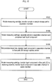
- the liquid transfer method according to this aspect includes, separating (S102) a blood sample (70, 280) into a blood cell component (71, 281) and a plasma component (72, 282) using a centrifugal force due to rotation around a rotating shaft (20, 103) in a separation chamber (30, 210) included in a measuring cartridge (10, 200, 320) mounted on a measuring device so as to be rotatable about a rotating shaft (20, 103), filling (S103), by capillary action, a flow path (50, 200) connecting the separation chamber (30, 210) and receiving chamber (40, 241) with the plasma component (72, 282) separated in the separation chamber(30, 210), and transporting (S104) the quantified plasma component (72, 282) to the receiving chamber (40, 241) by introducing air into the flow path (50, 200) by centrifugal force.
- the effect obtained is the same as in the second aspect.
- the movement of the plasma component (72, 282) through capillary action is stopped (S103) on the storage chamber (40, 241) side of the flow path (50, 200).
- the present invention it is possible to prevent the contamination of the blood cell component when transferring the plasma component separated by centrifugation, and to improve the measurement accuracy of the plasma component.
- the measuring cartridge 10 is a measuring cartridge for separating a liquid component from a sample by centrifugal separation, and subjecting the liquid component to measurement.
- the measuring cartridge 10 is a replaceable part that consolidates functions necessary for separating a liquid component from a sample by centrifugal separation.
- the measuring cartridge 10 is mounted on the measuring device so as to be rotatable around the rotating shaft 20 of the measuring device, and is configured to be capable of separating the sample accommodated therein into a solid component and a liquid component by centrifugal force.
- the measuring device rotates the rotating shaft 20 to rotate the mounted measuring cartridge 10 around the rotating shaft 20.
- the sample is a blood sample of whole blood collected from the donor.
- the liquid component is a plasma component contained in a blood sample of whole blood.
- the solid component is a blood cell component contained in a blood sample of whole blood. Note that the sample is not limited to a blood sample of whole blood, inasmuch as the sample is collected from a subject.
- the liquid component is not limited to the plasma component and may be any liquid component contained in the sample collected from the subject.
- the solid component is not limited to the blood cell component and may be any solid component contained in the sample collected from the subject.
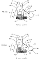
- FIG. 1 is a schematic view of the measuring cartridge 10 mounted on the measuring device viewed in the vertical downward direction.
- the XYZ axes are orthogonal to each other.
- the X-axis positive direction indicates the backward direction
- the Y-axis positive direction indicates the left direction
- the Z-axis positive direction indicates the vertical downward direction.
- the XYZ axes also are the same as the XYZ axes in FIG. 1 .
- the radial direction of a circle centered on the rotating shaft 20 is referred to simply as the "radial direction”.
- the circumferential direction of a circle centered on the rotating shaft 20, that is, the rotating direction around the rotating shaft 20, is referred to simply as the "rotation direction”.
- the counterclockwise rotation as viewed in the Z axis positive direction is set as the T1 direction
- the clockwise direction as viewed in the Z axis positive direction is set as the T2 direction.
- the measuring cartridge 10 is configured by a plate-like and disk-shaped substrate 10a. Each part in the measuring cartridge 10 is formed by adhering a concave part in the substrate 10a and a film (not shown) covering the substrate 10a.
- the measuring cartridge 10 is not limited to being in the form of a plate, and may include a protruding part or the like, and is not limited to a disk shape and may be in other shapes such as a rectangular shape.
- the substrate 10a is provided with a hole 10b penetrating the substrate 10a at the center of the substrate 10a.
- the measuring cartridge 10 is installed in the measuring device so that the center of the hole 10b coincides with the rotating shaft 20 of the measuring device.
- the measuring cartridge 10 includes a separation chamber 30, a receiving chamber 40, a flow path 50, a sample input port 61, a sample storage part 62, a flow path 63, a hole 64, an air introduction path 65, and a flow path 66.
- the sample input port 61 is provided radially inner side of the sample storage part 62, and opens the inner side in the radial direction of the sample storage part 62 to the outside of the measuring cartridge 10.
- the sample storage part 62 accommodates the sample introduced from the sample input port 61.
- the flow path 63 is provided radially outer side of the sample storage part 62, and connects the sample storage part 62 and the separation chamber 30.
- the separation chamber 30 has a first storage part 31 and a second storage part 32 arranged in a direction away from the rotating shaft 20 with respect to the first storage part 31.
- the second storage part 32 is connected to the first storage part 31.
- the first storage part 31 extends toward the rotating shaft 20, and the second storage part 32 extends along the rotation direction.
- the width L2 of the second storage part 32 in the rotation direction is larger than the width L1 of the first storage part 31 in the rotation direction.
- the first storage part 31 is disposed at a position biased in the T2 direction relative to the second storage part 32 in the rotation direction.
- the first storage part 31 includes inner walls 31a and 31b.
- the inner walls 31a and 31b are parts of the first storage part 31 located on the opposite side of the rotating shaft 20 from the end part of the first storage part 31 positioned on the rotating shaft 20 side.
- the inner wall 31 a is positioned on the T1 direction side of the first storage part 31 and the inner wall 31b is positioned on the T2 direction side of the first storage part 31.
- the inner walls 31 a, 31b extend in the radial direction.
- the inner wall 31b is connected to the inner wall on the T2 direction side of the second storage part 32 in the same plane.
- the flow path 63 is connected to the inner wall 31 b.
- the second storage part 32 includes an inner wall 32a connected to the first storage part 31.
- the inner wall 32a is located at the end on the side of the rotary shaft 20 of the second storage part 32, and located on the T1 direction side of the first storage part 31. In a plan view, the inner wall 32a extends in the rotation direction.
- the flow path 50 is connected to the inner wall 32a.
- the flow path 50 connects the separation chamber 30 and the receiving chamber 40.
- the flow path 50 extends in a direction from the separation chamber 30 toward the rotating shaft 20.
- the flow path 51 of the flow path 50 connected to the separation chamber 30, which will be described later, extends in the direction toward the rotating shaft 20.
- the flow path 51 shown in FIG. 1 extends in the direction toward the rotating shaft 20
- the flow path 51 does not necessarily extend in the radial direction.
- the flow path 50 also does not necessarily extend in the direction toward the rotating shaft 20 over the entire length, and may extend in the direction toward the rotating shaft 20 at least within a range in which the sample can enter before centrifugal separation.
- the flow path 50 includes a flow path 51 and a flow path 52.
- the flow path 51 linearly extends from the separation chamber 30 toward the rotating shaft 20.
- the flow path 52 extends linearly in a direction away from the rotating shaft 20 from an end part of the flow path 51 on the side opposite the separation chamber 30.
- An end part of the flow path 51 on the T2 direction side is connected to the separation chamber 30, and an end part on the T1 direction side of the flow path 52 is connected to the receiving chamber 40.
- the end of the flow path 51 on the side opposite the separation chamber 30 and the end part of the flow path 52 on the side opposite the receiving chamber 40 are connected to each other at the connection position 50a.
- the flow path 50 is configured so that a liquid component separated in the separation chamber 30 moves from the separation chamber 30 toward the receiving chamber 40 through the flow path 50 by capillary action. Therefore, the inner diameter of the flow path 50 is set small enough to allow the liquid component to move by capillary action.
- a hole 64 is provided on the inner side in the radial direction of the air introduction path 65, and opens the inner side in the radial direction of the air introduction path 65 to the outside of the measuring cartridge 10.
- the air introduction path 65 is connected to the connection position 50a of the flow path 50, and introduces air into the flow path 50 at the connection position 50a. Specifically, the air introduction path 65 introduces air into the flow path 51 from the connection position 50a, and introduces air into the flow path 52 from the connection position 50a.
- the receiving chamber 40 is a chamber for accommodating a liquid component separated by the separation chamber 30.
- the flow path 66 is connected to the receiving chamber 40. The liquid component transferred to the receiving chamber 40 via the flow path 50 is transferred to the another receiving chamber via the flow path 66 and the liquid component is measured in the other receiving chamber.
- the operator inserts the sample 70 into the sample input port 61 in advance and causes the sample storage part 62 to receive the sample 70.
- the operator mounts the measuring cartridge 10 in the measuring device and starts the operation by the measuring devices.
- the measuring device rotates the measuring cartridge 10 around the rotating shaft 20, and transfers the sample 70 accommodated in the sample storage part 62 to the separation chamber 30 via the flow path 63 by centrifugal force.
- the interface between the sample 70 and the air layer in the separation chamber 30 is located radially inner side of the position where the flow path 51 is connected to the inner wall 32a of the separation chamber 30. In this way, the sample 70 enters the vicinity of the end part of the flow path 51 on the separation chamber 30 side.
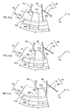
- the measuring device rotates the measuring cartridge 10 around the rotating shaft 20 from the state shown in FIG. 2 (a) , and centrifugally moves the sample 70 accommodated in the separation chamber 30 by rotation around the rotating shaft 20 so that the sample 70 is separated into a solid component 71 and a liquid component 72.
- the solid component 71 moves radially outward
- the liquid component 72 moves radially inward.
- the flow path 50 extends from the separation chamber 30 in the direction toward the rotating shaft 20, as shown in FIG.
- the flow path 51 of the first embodiment extends radially from the inner wall 32a.
- the solid component 71 can enter the flow path 51 from the separation chamber 30 before centrifugation and accumulate in the flow path 51, then moves more smoothly to the first storage part 31 by centrifugal force during centrifugation. Therefore, it is possible to more reliably prevent the solid component 71 from remaining in the flow path 50 after centrifugal separation.
- the measuring device stands by for a predetermined time without rotating the measuring cartridge 10 from the state of FIG. 2 (b) .
- the liquid component 72 in the separation chamber 30 enters the flow path 50 by capillary action, and the inside of the flow path 50 is filled with the liquid component 72.
- the interface between the air layer and the liquid component 72 appearing in the first storage part 31 after the centrifugation is much farther from the second storage part 32 toward the rotating shaft 20 side.
- the distance between this interface and the liquid layer of the solid component 71 after centrifugal separation can be increased, and the flow path 50 can be connected at a position distant from the liquid layer of the solid component 71.
- the flow path 50 can be connected to the inner wall 32a of the second storage part 32. In this way, it is possible to prevent the centrifugally separated solid component 71 from being caught in the flow generated by the capillary phenomenon.
- the measuring device rotates the measuring cartridge 10 around the rotating shaft 20 from the state of FIG. 3 (a) .
- a centrifugal force is applied to the liquid component 72 in the flow path 50, and the liquid component 72 in the flow path 51 is returned to the separation chamber 30 by centrifugal force, and the liquid component 72 in the flow path 52 is moved to the receiving chamber 40 by centrifugal force.
- the flow path 50 introduces air from the connection position 50a into the flow path 50, transfers the liquid component 72 that filled between the connection position 50a and the separation chamber 30 into the separation chamber 30, and transfers the liquid component 72 that filled between the container 50a and the receiving chamber 40 into the receiving chamber 40. Since the liquid component 72moving to the receiving chamber 40 becomes the liquid component 72 that fills the flow path 52, the quantitativeness of the liquid component 72 moving to the receiving chamber 40 is improved. That is, it is possible to transport the liquid component 72 in an amount necessary for measurement to the receiving chamber 40 without excess or deficiency.
- the first storage part 31 of the first embodiment was disposed at a position biased in the T2 direction relative to the second storage part 32 in the rotation direction.
- the present invention is not limited to this arrangement inasmuch as the first storage part 31 may be disposed in the vicinity of the center position of the second storage part 32 as shown in FIG. 4 (a) in the rotation direction, and may be disposed at a position deviated in the T1 direction relative to the second storage part 32, as shown in FIG. 4 (b) .
- the second storage part 32 is provided with an inner wall 32b connected to the first storage part 31 and positioned on the T2 direction side of the first storage part 31.
- the inner wall 32b extends in the rotation direction.
- the second storage part 32 includes only the inner wall 32b among the inner walls 32a and 32b, as compared with FIG. 4 (a) .
- the inner wall 31a of the first storage part 31 is connected to the inner wall of the second storage part 32 on the T1 direction side in the same plane.
- the flow path 50 is connected to the inner wall 31a.
- the flow path 50 is not limited to being connected to the inner wall 32a as shown in FIG. 1 and FIG. 4(a) , inasmuch as the flow path 50 also may be connected to the part of the second storage part 32 positioned on the rotating shaft 20 side from the end part of the second storage part 32 disposed on the side opposite the rotating shaft 20. Specifically, the flow path 50 may be connected to the inner wall 32b in FIGS. 4 (a) and 4 (b) , and the flow path 50 also may be connected to the inner wall on the T1 direction side or the T2 direction side of the second storage part 32 in FIGS. 1 and 4(a) .
- the flow path 50 is not limited to being connected to the inner wall 31a as shown in FIG. 4 (b) , and also may be connected to part of the first storage part 31 positioned on the opposite side relative to rotating shaft 20 from the end part of the first storage part 31 located on the rotation shaft 20 side. Specifically, the flow path 50 may be connected to the inner wall 31a in FIGS. 1 and 4(a) , or may be connected to the inner wall 31b in FIG. 1 and FIGS. 4(a) and 4 (b) .
- the flow path 50 also may be connected to the separation chamber 30 at the connection between the inner wall 31a and the inner wall 32b.
- the flow path 50 also may be connected to the separation chamber 30 at the connection between the inner wall 31b and the inner wall 32b.
- the flow path 50 also may be connected to the separation chamber 30 at a connection part between the first storage part 31 and the second storage part 32 in a plane including the inner wall 31b, as shown in FIG. 1 .
- the flow path 50 also may be connected to the separation chamber 30 at a connection part between the first storage part 31 and the second storage part 32 in a plane including the inner wall 31a shown in FIG. 4 (b) .
- the flow path 63 was connected to the separation chamber 30 on the inner wall 31b of the first storage part 31.
- the flow path 63 is not limited to this arrangement, and may be connected to the separation chamber 30 on the inner wall 31a of the first storage part 31 or to the separation chamber 30 on the inner wall of the first storage part 31 located on the rotation shaft 20 side.
- the separation chamber 30 also is provided a protruding part 30a that projects the inner wall part on the radial direction side of the second storage part 32 in the T2 direction in comparison with the configuration of the first embodiment shown in FIG. 1 .
- the second storage part 32 of the second embodiment includes a first area 81, and a second area 82 arranged on the rotation shaft 20 side relative to the first area 81.
- the width L2 of the second area 82 in the rotation direction is smaller than the width L3 of the first area 81 in the rotation direction.
- the second area 82 is disposed at a position biased in the T1 direction relative to the first area 81.
- the first area 81 includes an inner wall 81a extending along the rotation direction in plan view.
- the inner wall 81a is positioned on the T2 direction side in the first area 81 and is connected to the second area 82.
- the inner wall 81a is located at the end of the first area 81 on the rotation shaft 20 side.
- the solid component 71 can be efficiently accommodated in the wide first area 81 during centrifugal separation.
- the interface between the specimen 70 and the air layer can be positioned radially outwardly in the separation chamber 30 by providing the protruding part 30a. In this way, the sample 70 can be centrifuged in a short time.
- the liquid layer of the solid component 71 also is moved away from the rotating shaft 20 by providing the protruding part 30a, compared with the first embodiment. In this way, it is possible to prevent the solid component 71 from getting caught in the flow to the flow path 50 due to capillary action.
- the width L2 of the second area 82 is smaller than the width L3 of the first area 81, the interface between the air layer and the liquid component 72 after the centrifugal separation is located closer to the rotary shaft 20 side compared with the case where the entire inner wall on the T2 direction side of the second storage part 32 protrudes in the T2 direction from the configuration of FIG. 1 .
- the connection position of the flow path 50 relative to the separation chamber 30 can be brought close to the rotating shaft 20, the connection position of the flow path 50 is far from the liquid layer of the solid component 71. In this way, it is possible to more reliably prevent the solid component 71 from being caught in the flow to the flow path 50 through capillary action.
- the first storage part 31 of the second embodiment is disposed at a position deviated to the T2 direction side relative to the second area 82, and the flow path 50 is disposed at a position of the second area 82 on the T1 direction side relative to the first storage part 81.
- the flow path 50 is connected to the inner wall 32a in this manner, it is possible to prevent the liquid component 72 from moving away from the connection position on the inner wall 32a of the flow path 50 while the liquid component 72 flows into the flow path 50 via capillary action. In this way, the liquid component 72 can be stably supplied to the flow path 50 while the liquid component 72 flows into the flow path 50 due to capillary action. Note that the manner in which the interface between the air layer and the liquid component 72 advances in this case will be described in detail in a specific configuration example described later.
- the separation chamber 30 of the second embodiment provides a protruding part 30a on the inner wall on the T2 direction side of the second storage part 32 in the configuration shown in FIG. 1 .
- the separation chamber 30 also may be configured by providing the protrusion 30a similar to FIG. 5 (a) in the configuration shown in FIG. 4 (a) as shown in FIG. 5 (b) .
- the separation chamber 30 also may be configured by providing the protrusion 30a similar to FIG. 5 (a) in the configuration shown in FIG. 4 (b) .
- the flow path 51 is connected to the border position between the first storage part 31 and the second storage part 32.
- the separation chamber 30 is provided with a protruding part 30b that projects the inner wall part to the outer side in the radial direction among the inner wall on the T1 side of the second storage part 32, in comparison with the configuration of the second embodiment shown in FIG. 5 (a) .
- the first area 81 of the third embodiment has a shape extending in the T1 direction as compared with the second embodiment.
- the first area 81 further includes an inner wall 81 b extending along the rotation direction in plan view.
- the inner wall 81 b is positioned on the T1 direction side and the radial direction inner side in the first area 81, and is connected to the second area 82.
- the width L3 of the first area 81 is longer than the width L3 of the second embodiment.
- the solid component 71 can be accommodated more efficiently in the first area 81 during centrifugal separation.
- the interface between the sample 70 and the air layer also can be positioned radially outwardly in the separation chamber 30 by providing the protruding part 30b, as compared with the second embodiment. In this way, the sample 70 can be centrifuged in a shorter time.
- the liquid layer of the solid component 71 also is further away from the rotating shaft 20 by providing the protruding portion 30 b, as compared with the second embodiment. In this way, it is possible to further suppress the solid component 71 from getting caught in the flow to the flow path 50 through capillary action.
- a protruding part 30b is provided on the inner wall on the T1 direction side of the second storage part 32 in the configuration shown in FIG. 5 (a) .
- the separation chamber 30 also may provide the protrusion 30b similar to FIG. 6 (a) in the configuration shown in FIG. 5 (b) , as shown in FIG. 6 (b) .
- the separation chamber 30 also may provide the protruding part 30b similar to FIG. 6 (a) in the configuration shown in FIG. 5 (c) , as shown in the configuration of FIG. 6 (c) .
- the measuring device 100 uses a measuring cartridge 200 to separate a liquid component from a sample, detect a target substance in the liquid component by utilizing antigen-antibody reaction, and analyze the target substance based on the detection result.
- the sample is a blood sample of whole blood collected from a donor.
- the liquid component is a plasma component contained in a blood sample of whole blood.
- the solid component is a blood cell component contained in a blood sample of whole blood.
- the measuring device 100 includes a main body 101 and a lid 102.
- the main body 101 In the main body 101, the part other than a part facing the lid 102 is covered with the housing 101a.
- the lid 102 In the lid 102, the part other than the part facing the main body 101 is covered with the housing 102a.
- the main body 101 supports the lid 102 so as to be openable and closable.
- the lid 102 When attaching and detaching the measuring cartridge 200, the lid 102 is opened as shown in FIG. 7 (a) .
- the measuring cartridge 200 is mounted on the upper part of the main body 101.
- the main body 101 also includes a rotating shaft 103 extending parallel to the Z axis direction.
- the rotating shaft 103 corresponds to the rotating shaft 20 in FIG. 1 .
- the measuring device 100 rotates the attached measuring cartridge 200 around the rotating shaft 103.
- the internal configuration of the measuring device 100 will be described later with reference to FIGS. 11 to 13 .
- the measuring cartridge 200 corresponds to the measuring cartridge 10 of the second embodiment shown in FIG. 5 (a) .
- the measuring cartridge 200 is configured by a plate-like and disk-shaped substrate 200a.
- FIG. 5 (a) shows a part of the measuring cartridge 200.
- Each part in the measuring cartridge 200 is formed by adhering a concave part formed in the substrate 200a and a film (not shown) covering the substrate 200a.
- the substrate 200a and the film adhered to the substrate 200a are made of a light-transmitting member.
- the thickness of the substrate 200a is, for example, several millimeters, specifically 1.2 mm.
- the substrate 200a is provided with a hole 200b penetrating the substrate 200a at the center of the substrate 200a.
- the measuring cartridge 200 is installed in the measuring device 100 so that the center of the hole 200b coincides with the rotating shaft 103 of the measuring device 100.
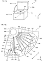
- the measuring cartridge 200 includes a sample input port 201, a sample storage part 202, a flow path 203, holes 204 and 206, air introduction paths 205 and 207, valves 208a, 208b and 208c, a separation chamber 210, a flow path 220, a flow path 231, an overflow chamber 232, a flow path 233, a waste chamber 234, receiving chambers 241 to 246, a flow path 250, a liquid storage part 261, and a hole 262.
- the sample input port 201, the sample storage part 202, and the flow path 203 correspond to the sample input port 61, the sample storage part 62, and the flow path 63 shown in FIG. 1 , respectively.
- the valve 208a is provided between the sample storage part 62 and the flow path 203. Before the measuring cartridge 200 is rotated, the valve 208a restrains the sample accommodated in the sample storage part 202 from moving to the flow path 203.
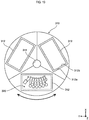
- the separation chamber 210 includes a first storage part 211 and a second storage part 212, and the second storage part 212 includes a first area 271 and a second area 272.
- the separation chamber 210 corresponds to the separation chamber 30 shown in FIG. 5 (a)
- the first storage part 211 and the second storage part 212 correspond to the first storage part 31 and the second storage part 32
- the first area 271 and the second area 272 correspond to the first area 81 and the second area 82 shown in FIG. 5(a) , respectively.
- the first storage part 211 includes an inner wall 211 a
- the second storage part 212 includes an inner wall 212a.
- the inner walls 211 a and 212a correspond to the inner walls 31a and 32a shown in FIG. 5 (a) , respectively.
- the inner wall 211 a is connected to the inner wall 21 a by a curved inner wall 211b which is inclined so as to be gradually parallel to the inner wall 212a from an end edge on the inner wall 212a side of the inner wall 211a, and is connected to the inner wall 212a. That is, the inner wall 211 a extending in the radial direction in plan view and the inner wall 212a extending in the rotation direction in plan view are smoothly connected by the curved inner wall 211 b.
- the first region 271 includes an inner wall 271 a.
- the inner wall 271 a corresponds to the inner wall 81a shown in FIG. 5 (a) .
- the width in the rotation direction of the inner wall 271a is larger than the width in the rotation direction of the inner wall 212a.
- the protruding portion 210a is a part of the first area 271 protruding in the T2 direction relative to the second area 272.
- the protruding part 210a corresponds to the protruding part 30a shown in FIG. 5 (a) .
- An air introduction path 205 is connected to the inner wall of the separation chamber 30 extending in the radial direction on the inner side in plan view.
- the hole 204 is provided radially inward of the air introduction path 205, and opens the inside of the air introduction path 205 in the radial direction to the outside of the measuring cartridge 200.
- An air introduction path 207 is connected to the connection position 220a of the flow path 220.
- the hole 206 is provided radially inward of the air introduction path 207, and opens the inside of the air introduction path 207 in the radial direction to the outside of the measuring cartridge 200.
- the air introduction path 207 introduces air into the flow path 220 at the connection position 220a.
- the hole 206, the air introduction path 207, and the connection position 220a correspond to the hole 64, the air introduction path 65, and the connection position 50a shown in FIG. 1 , respectively.
- the valve 208b is provided between the air introduction path 207 and the connection position 220a. The valve 208b prevents the liquid component that enters the flow path 220 through capillary action from entering the air introduction path 207.
- the flow path 220 includes a flow path 221 and a flow path 222.
- the flow path 220 corresponds to the flow path 50 shown in FIG. 5 (a)
- the flow path 221 and the flow path 222 correspond to the flow path 51 and the flow path 52 shown in FIG. 5(a) .
- the valve 208c is provided between the flow path 222 and the storage chamber 241 on the side of the storage chamber 241 of the flow path 222.
- the valve 208c is provided to stop the movement of the liquid component through capillary action. That is, the valve 208c prevents the liquid component that enters the flow path 220 from the separation chamber 210 via capillary action from entering the receiving chamber 241.
- the flow path 231 connects the flow path 221 and the overflow chamber 232. Specifically, the end of the flow path 231 on the flow path 221 side is connected to the branching position 221 a that is closer to the separation chamber 210 than the center of the flow path 221.
- the flow path 231 is provided with a storage part 231a.
- the overflow chamber 232 contains unnecessary analytes and unnecessary liquid component. In other words, the overflow chamber 232 is provided for discarding unnecessary sample and unnecessary liquid component.
- the flow path 233 connects the first area 271 and the waste chamber 234. Specifically, one end part of the flow path 233 is connected to the inner wall 271a of the first area 271.
- the flow path 233 moves the liquid component remaining in the separation chamber 210, after the liquid component is moved from the separation chamber 210 to the storage chamber 241, from the first area 271 to the waste chamber 234 according to the siphon principle.
- Waste chamber 234 contains unnecessary liquid component. That is, the waste chamber 234 is provided for discarding unnecessary liquid component.
- the receiving chambers 241 to 246 are arranged in the rotation direction near the outer periphery of the substrate 200a.
- the receiving chamber 241 corresponds to the receiving chamber 40 shown in FIG. 1 .
- the flow path 250 includes an arcuate region extending in the rotation direction, and a region for moving the reagent in the liquid storage part 261 toward the corresponding receiving chamber.
- the liquid storage part 261 contains reagents and includes sealing bodies 261a and 261 b.
- the sealing bodies 261 a, 261 b are configured to be able to be opened by being pushed from above by a pressing part 124 described later.
- the sealing bodies 261a and 261b When the sealing bodies 261a and 261b are opened, the inner side in the radial direction of the liquid storage part 261 is opened to the outside of the measuring cartridge 200 via the hole 262, and the outer side in the radial direction of the liquid storage part 261 is connected to the flow passage 250. In this way, the reagent in the liquid storage part 261 can be transferred to the corresponding receiving chamber among the receiving chambers 241 to 246 via the flow path 250 through centrifugal force.
- Each configuration of the measuring cartridge 200 shown in FIG. 7 (b) is formed only in one third of the area of the substrate 200a.
- the present invention is not limited to this arrangement inasmuch as a group of these configurations may be formed in the remaining two-thirds region, and three groups of structures may be provided on the substrate 200a.
- FIG. 9 (a) is a diagram schematically showing the configuration of the separation chamber 210 when the cross section of C1 - C2 shown in FIG. 8 is viewed in the Y axis negative direction.
- the X-axis positive direction indicates a direction toward the rotation axis 103
- the X-axis negative direction indicates a direction away from the rotation axis 103.
- the separation chamber 210 has a lower surface 273 as an inner wall located on the Z axis positive direction side, and an upper surface 274 as an inner wall located on the Z axis negative direction side.
- the lower surface 273 is a flat surface parallel to the XY plane.
- the upper surface 274 includes a first inclined part 274a, a second inclined part 274b, and flat parts 274c, 274d, and 274e.
- the first inclined part 274a increases the thickness of the space in the second storage part 212 as the distance from the rotation shaft 103 increases.
- the first inclined part 274a is provided in the first area 271 of the separation chamber 210.
- the second inclined part 274b reduces the thickness of the space in the second storage part 212 as it moves away from the rotating shaft 103.
- the second inclined part 274b is provided in the second area 272 of the separation chamber 210.
- the flat part 274c is a flat surface parallel to the XY plane and connects the first inclined part 274a and the second inclined part 274b.
- the flat part 274d is a flat surface parallel to the XY plane, and the thickness of the space in the second storage part 212 in the first rare 271 is defined as H1.
- the flat part 274e is a flat surface parallel to the XY plane, and the thickness of the space in the second storage part 212 in the second area 272, and the thickness of the space in the first storage part 211 are defined as H2.
- the flat part 274c regulates the thickness of the space in the second storage part 212 at the border between the first area 271 and the second area 272 to H3.
- the relationship between the thicknesses H1 to H3 is H1>H2>H3.
- the first inclined portion 274a By providing the first inclined portion 274a, it is possible to increase the thickness of the area radially outside of the first inclined portion 274a to increase the capacity of the area radially outward of the first inclined portion 274a. In this way, it easier for the solid component to stay in an area radially outward of the first inclined part 274a during centrifugation due to the boycott effect, thereby increasing centrifugal separation efficiency.
- the solid component can be efficiently collected in the area radially outward of the first inclined part 274a since the liquid component is smoothly moved along the first inclined part 274a to the inner side in a radial direction from the outer side in the radial direction of the second storage part 212.
- the second inclined part 274b By providing the second inclined part 274b, it is possible to reduce the thickness of the area on the outer side in the radial direction by the second inclined part 274b to reduce the thickness of the area on the radially outer side from the second inclined part 274b. In this way, the solid component moved to the outer side in the radial direction from the second inclined part 274b by centrifugal force is unlikely to return to the radially inner side. Hence, mixing of the solid component into the flow path 220 after the centrifugal separation can be effectively prevented. The solid component can be smoothly moved outward in the radial direction of the second inclined part 274b along the second inclined part 274b during centrifugal separation.
- a convex part is disposed between the first area 271 in which the solid component is stored and the second area 272 in which the liquid component is stored by providing the first inclined part 274a and the second inclined part 274b.
- a flat part 274c protruding in a direction of reducing the thickness of the separation chamber 30 is provided between the first area 271 and the second area 272. In this way, it is possible to prevent the solid component from mixing into the liquid component more effectively.
- the thickness of the space in the second storage part 212 in the first are 271 is H1
- the thickness of the space in the second storage part 212 in the second area 272 is H2 which is smaller than H1. In this way, the solid component can be efficiently retained in the first area 271.
- the first inclined part 274a and the second inclined part 274b are connected by a flat part 274c.
- the solid component does not easily move in the range where the flat part 274c is provided, so that the solid component retained at the outer side in the radial direction from the first inclined part 274a by the centrifugal separation passes through the flat part 274c, and mixing with the liquid component is prevented.
- the separation chamber 210 is not limited to being configured as shown in FIG. 9 (a) , and may be configured as shown in FIGS. 9 (b) and 9 (c) , for example.
- the first inclined part 274a and the flat part 274c are omitted on the upper surface 274 of the separation chamber 210, as compared with FIG. 9 (a) .
- the effect of the second inclined part 274b also is obtained.
- the second inclined part 274b and the flat part 274c are omitted on the upper surface 274 of the separation chamber 210, as compared with FIG. 9 (a) .
- the effect by the first inclined part 274a also is obtained.
- the flat part 274c may be omitted, and the first inclined part 274a and the second inclined part 274b may be adjacent to each other.
- the configuration of the inclined part, the flat part and the like is not limited to being provided on the upper surface 274, and also may be provided on the lower surface 273, or may be provided on both the lower surface 273 and the upper surface 274.
- the inclined surface of the first inclined part 274a and the inclined surface of the second inclined part 274b need not necessarily have a flat surface as shown in FIG. 9 (a) , and may have irregularities.
- the first inclined part 274a may be omitted, and the flat part 274c and the flat part 274d may be connected by a flat surface parallel to the YZ plane.
- the first inclined part 274a may be omitted, and the flat part 274d and the flat part 274e may be connected by a flat surface parallel to the YZ plane.
- the second inclined part 274b may be omitted, and the flat part 274c and the flat part 274e may be connected by a flat surface parallel to the YZ plane.
- the second inclined part 274b may be omitted, and the flat part 274d and the flat part 274e may be connected by a flat surface parallel to the YZ plane.
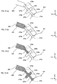
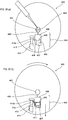
- FIG. 10 (a) is an enlarged view schematically showing the vicinity of the valve 208c.
- the valve 208c includes a flow path 275a, a space 275b, and a flow path 275c.
- the flow path 275a is connected to the flow path 222, and the flow path 275c is connected to the receiving chamber 241.
- the space 275b connects the flow path 275a and the flow path 275c.
- the flow path 275a is configured so that the width of the flow path 275a sharply decreases as compared with the size of the flow path 222 in the connection part 276a between the flow path 222 and the flow path 275a.
- the space 275b is configured so that the space 275b abruptly increases in size at the connecting part 276b between the flow path 275a and the space 275b as compared with the size of the flow path 275a.
- the flow path 275c is configured such that the width of the flow path 275c is sharply smaller than the size of the receiving chamber 241 in the connection part 276c between the flow path 275c and the receiving chamber 241.
- the cross-sectional area of the flow paths 275a and 275c is constant. Note that the cross-sectional areas of the flow paths 275a and 275c need not necessarily be constant.
- the flow paths 275a, 275c, and the space 275b are configured to have low wettability with respect to liquid.
- the width of the flow path 275a is abruptly smaller than the size of the flow path 222, and the flow path 275a has low wettability with respect to liquid.
- the liquid component 282 in the flow path 222 reaches the connecting part 276a due to capillary action, the liquid component 282 is unlikely to intrude into the flow path 275a.
- the liquid component 282 in the flow path 222 does not enter the flow path 275a for the above-mentioned reason.
- the liquid component 282 in the flow path 222 may enter the flow path 275a due to capillary action. Therefore, the valve 208c is provided with a space 275b and a flow path 275c in addition to the flow path 275a.
- the size of the space 275b is abruptly larger than the size of the flow path 275a, and the space 275b has low wettability with respect to liquid.
- the liquid component 282 in the flow path 275a is unlikely to enter the space 275b due to the surface tension of the liquid component 282.
- the size of the receiving chamber 241 becomes abruptly larger than the size of the flow path 275c. In this way, even if the liquid component 282 reaches the connecting part 276c through capillary action, the liquid component 282 in the flow path 275c is unlikely to intrude into the receiving chamber 241 due to the surface tension of the liquid component 282, as shown in FIG. 10 (d) . Hence, it is possible to reliably prevent the liquid component 282 of the flow path 222 from entering the receiving chamber 241 through capillary action.
- valve 208a also has flow paths 275a, 275c and a space 275b similar to the valve 208c. That is, the size of the flow path inside the valve 208a becomes abruptly smaller than the size of the sample storage part 202 and the flow path 203, and the size of the space within the valve 208a becomes abruptly larger compared to the size of the flow path inside the valve 208a. In this way, the valve 208a can prevent the sample in the sample storage part 202 from entering the flow path 203 through capillary action.
- the valve 208b also has flow paths 275a, 275c and a space 275b.
- the size of the flow path inside the valve 208b becomes abruptly smaller than the size of the air introduction path 207 and the flow path 220, and the space in the valve 208b becomes abruptly larger compared to the size of the flow path inside the valve 208b.
- the valve 208b can prevent the liquid component in the flow path 220 from entering the air introduction path 207 through capillary action.
- the internal configuration of the measuring device 100 will be described below referring to FIGS. 11 to 13 .
- the main body 101 includes a mounting member 111, a plate member 112, a support member 113, a magnetic force applicator 114, a detection unit 115, a housing body 116, a motor 117, and an encoder 118.
- the mounting member 111 has a shape to be fitted into the casing 101a.
- the plate member 112 is installed at the center of the upper surface of the mounting member 111.
- the plate member 112 is made of a metal having high thermal conductivity.
- the support member 113 is installed at the center of the mounting member 111 via a mounting member 119 to be described later.
- the support member 113 is configured by, for example, a turn table.
- the magnetic force applicator 114 is installed on the lower surface of the mounting member 111 so as to face the lower surface of the measuring cartridge 200 installed on the support member 113 via holes formed in the mounting member 111 and the plate member 112.
- the magnetic force applicator 114 includes a magnet and a mechanism for moving the magnet in the Z axis direction and the radial direction.
- the detection unit 115 is installed on the lower surface of the mounting member 111 so as to face the lower surface of the measuring cartridge 200 installed on the support member 113 via holes formed in the mounting member 111 and the plate member 112.
- the detection unit 115 includes a photodetector.
- the photodetector of the detection unit 115 optically detects the test substance contained in the receiving chamber 246.
- the photodetector of the detection unit 115 is composed of, for example, a photomultiplier tube, a photoelectric tube, a photodiode or the like.
- the housing body 116 is installed on the lower surface of the mounting member 111.
- the housing body 116 includes a lower surface 116a and storage parts 116b and 116c.
- a hole 116d (described later) is formed at the center of the upper surface of the housing body 116.
- the hole 116d vertically penetrates from the upper surface of the housing body 116 to the lower surface 116a.
- a rotating shaft 103 passes through the hole 116d.
- the storage parts 116b and 116c are configured by concave parts recessed downward from the upper surface of the housing body 116.
- the storage parts 116b and 116c accommodate the magnetic force applying portion 114 and the detecting portion 115, respectively.
- the motor 117 is configured by a stepping motor.
- the motor 117 is installed on the lower surface 116a and rotates the rotating shaft 103 about the Z axis as the center of rotation.
- the encoder 118 is installed on the lower surface of the motor 117 and detects the rotation of a drive shaft 117a of the motor 117, which will be described later.
- FIG. 11 also shows a state in which the lid 102 is viewed from below.
- the lid 102 includes a mounting member 121, a plate member 122, a clamper 123, and two pressing parts 124.
- the mounting member 121 has a shape to fit in the housing body 102a.
- the plate member 122 is installed at the center of the lower surface of the mounting member 121.
- the plate member 122 is made of a metal having high thermal conductivity similar to the plate member 122.
- a heater 132 (described later) is installed on the upper surface of the plate member 122.
- the clamper 123 is installed at the center of the mounting member 121.
- the two pressing parts 124 are installed on the upper surface of the mounting member 121. When the lid 102 is closed, the two pressing parts 124 are arranged in the radial direction of the measuring cartridge 200 installed in the supporting member 113.
- the pressing part 124 on the inner side in the radial direction presses the sealing body 261 a from above through the hole formed in the mounting member 121 and the plate member 122, and opens the sealing body 261a by a pressing force.
- the pressing part 124 on the outer side in the radial direction presses the sealing body 261b from the upper side through the hole formed in the mounting member 121 and the plate member 122, and opens the sealing body 261b by a pressing force.
- the mounting member 111 and the housing body 116 assembled as shown in FIG. 11 are installed in the housing body 101a to complete the main body 101. Then, as shown in FIG. 11 , the lid 102 is installed in the main body part 101 by mounting the assembled lid 102 so as to be openable and closable relative to the mounting member 111 of the main body 101. In this way, the measuring device 100 is completed.
- FIG. 12 is a schematic diagram showing a cross section of the measuring device 100 cut along a plane parallel to the YZ plane passing through the rotating shaft 103.
- FIG. 12 shows the state in which the measuring cartridge 200 is installed in the measuring device 100, and the lid 102 is closed.
- the magnetic force applicator 114 and the detection unit 115 are installed on the lower surface of the mounting member 111, and two pressing parts 124 are installed on the upper surface of the mounting member 121.
- positions corresponding to the arrangement positions of these parts are indicated by broken lines.
- the drive shaft 117a of the motor 117 extends inside the hole 116d.
- a mounting member 119 is installed above the hole 116d.
- the mounting member 119 rotatably supports the rotating shaft 103 extending in the vertical direction.
- the rotating shaft 103 is fixed to the drive shaft 117a of the motor 117 by a locking member 117b inside the hole 116d.
- a support member 113 for supporting the lower surface of the measuring cartridge 200 is fixed to the upper part of the rotating shaft 103 via a predetermined member.
- the motor 117 is driven and the drive shaft 117a rotates, the rotational driving force is transmitted to the support member 113 via the rotating shaft 103.
- the measuring cartridge 200 installed on the support member 113 rotates around the rotating shaft 103.
- the clamper 123 presses the inner peripheral part of the upper surface of the measuring cartridge 200 in a rotatable state.
- a heater 131 is installed on the lower surface of the plate member 112, and a heater 132 is installed on the upper surface of the plate member 122.
- the heaters 131 and 132 have a flat heat generation surface, and the heat generation surface is parallel to the measuring cartridge 200. In this way, the measuring cartridge 200 can be efficiently heated.
- Temperature sensors 141 and 142 shown in FIG. 13 are installed on the plate members 112 and 122, respectively. The temperature sensors 141 and 142 detect the temperatures of the plate members 112 and 122, respectively.
- a controller 151 which will be described later, drives the heaters 131 and 132 to heat the temperature of the plate member 112 detected by the temperature sensor 141 and the temperature of the plate member 122 detected by the temperature sensor 142 to predetermined temperature.
- the magnetic force applicator 114 applies a magnetic force to the measuring cartridge 200 using a magnet as indicated by the upward dotted arrow in FIG. 12 .
- the detection unit 115 receives light generated from the receiving chamber 246 of the measuring cartridge 200 as indicated by a downward dotted arrow in FIG. 12 .
- the lid 102 When the lid 102 is closed, light is prevented from passing between the space where the measuring cartridge 200 is located and the outside. In this way, even if the light generated in the reaction process in the receiving chamber 246 is extremely weak, light generated by the reaction is detected by the photodetector of the detection unit 115 since light does not enter the space where the measuring cartridge 200 is located from the outside, and it becomes possible to detect with high accuracy.
- the measuring device 100 includes a magnetic force applicator 114, a detection unit 115, a motor 117, an encoder 118, a pressing part 124, heaters 131 and 132, temperature sensors 141 and 142, a controller 151, a display unit 152, an input unit 153, a drive unit 154, and a sensor unit 155.
- the controller 151 includes, for example, an arithmetic processing unit and a storage unit.
- the arithmetic processing unit is configured by, for example, a CPU, an MPU or the like.
- the storage unit is composed of, for example, a flash memory, a hard disk or the like.
- the controller 151 receives signals from each unit of the measuring device 100 and controls each unit of the measuring device 100.
- the display unit 152 and the input unit 153 are provided, for example, on a side surface part of the main body 101, an upper surface part of the lid 102 or the like.
- the display unit 152 is configured by, for example, a liquid crystal panel.
- the input unit 153 is configured by, for example, a button, a touch panel or the like.
- the drive unit 154 includes another mechanism disposed in the measuring device 100.
- the sensor unit 155 includes a sensor for detecting a predetermined part of the measuring cartridge 200 mounted on the support member 113, and another sensor disposed in the measuring device 100.
- the operator inserts the sample collected from the donor through the sample input port 201, and places the measuring cartridge 200 on the support member 113.
- the sample inserted from the sample input port 201 is received in the sample storage part 202.
- the target substance in the sample contains, for example, an antigen.
- an antigen is hepatitis B surface antigen (HBsAg).
- the target substance may be one or more of antigen, antibody, or protein.
- Prescribed reagents are stored in advance in the seven liquid storage parts 261 and the receiving chamber 241 of the measuring cartridge 200.
- the R1 reagent is contained in the liquid storage part 261 located in the radial direction of the receiving chamber 241.
- the R2 reagent is contained in the receiving chamber 241.
- the R3 reagent is contained in the liquid storage part 261 located in the radial direction of the receiving chamber 242.
- a cleaning liquid is contained in the liquid storage part 261 located in the radial direction of the receiving chambers 243 to 245.
- R4 reagent is contained in a liquid storage part 261 located in the radial direction of the receiving chamber 246.
- the R5 reagent is contained in the liquid storage part 261 adjacent to the T1 direction side of the liquid storage part 261 containing the R4 reagent.
- the controller 151 obtains the rotational position of the drive shaft 117a of the motor 117 based on the output signal of the encoder 118 connected to the motor 117.
- the controller 151 acquires the position in the rotation direction of the measuring cartridge 200 by detecting a predetermined part of the rotating measuring cartridge 200 with a sensor.
- the measuring cartridge 200 may be installed at a predetermined position with respect to the support member 113. In this way, the controller 151 can position each part of the measuring cartridge 200 at a predetermined position in the rotation direction.
- step S11 the controller 151 separates the sample and transfers the liquid component to the receiving chamber 241.
- step S 11 will be described below in detail with reference to FIG. 15 .
- the flowchart of FIG. 15 is a flowchart showing in detail the process of step S11 of FIG. 14 .
- FIG. 15 refers to the state transition diagrams of FIGS. 16(a) to 18(b) as appropriate.
- step S101 the controller 151 drives the motor 117 to rotate the measuring cartridge 200, and transfers the sample 280 in the sample storage part 202 to the separation chamber 210 by centrifugal force, as shown in FIG. 16 (b) .
- the interface between the sample 280 and the air layer approaches the rotating shaft 103 in the separation chamber 210, the flow path 233, and the flow path 221.
- the flow path 231 is connected to the flow path 221 at the branching position 221 a, when the interface between the sample 280 and the air layer surpasses the branching position 221a inward in the radial direction, the sample 280 that surpasses the branching position 221 a is discarded to the overflow chamber 232 through the flow path 231.
- step S102 the controller 151 drives the motor 117 to rotate the measuring cartridge 200, and the sample 280 in the separation chamber 210 undergoes separation by centrifugal force to separate the solid component 281 and the liquid component 282, as shown in FIG. 17 (a) .
- the interface between the solid component 281 and the liquid component 282 is positioned in the first region 271.
- the flow path 220 extends radially inward from the separation chamber 210, the sample 280 that entered the flow path 221 prior to centrifuging smoothly moves from the flow path 221 to the separation chamber 210, as shown in FIG. 16 (b) .
- step S103 the controller 151 waits for a predetermined time without rotating the measuring cartridge 200, whereby the liquid component 282 in the separation chamber 210 is transferred to the flow path 220 through capillary action, as shown in FIG. 17 (b) .
- the controller 151 waits for a predetermined time without rotating the measuring cartridge 200, whereby the liquid component 282 in the separation chamber 210 is transferred to the flow path 220 through capillary action, as shown in FIG. 17 (b) .
- the interface between the air layer and the liquid component 282 gradually moves outward in the radial direction as indicated by a dotted line in FIG. 17 (b) .
- the liquid component 282 in the separation chamber 210 also fills the flow path 233 via capillary action.
- the length of the first storage part 211 is shorter than the length of the second storage part 212 in the rotation direction, the interface between the air layer and the liquid component 282 appearing in the first storage part 211 after centrifugal separation is largely separated from the solid component 281.
- the position where the flow path 220 connects to the separation chamber 210 can be set to a position far away from the liquid layer of the solid component 281. In this way, it is possible to prevent the solid component 281 after centrifugation from mixing in the flow generated by capillary action in the flow path 50.
- a curved inner wall 211 b is provided between the inner wall 211 a of the first storage part 211 and the inner wall 212a of the second storage part 212.
- the first storage part 211 is disposed at a position biased in the T2 direction relative to the second area 272, and the flow path 50 is connected at a position of the second area 272 on the T1 direction side relative to the first storage part 211, such that, while the liquid component 282 flows into the flow path 220 via capillary action, the interface between the air layer and the liquid component 282 travels in a direction away from the rotating shaft 103 and the end part of the interface on the flow path 220 side is inclined in a state closer to the rotating shaft 103 than the end part of the interface on the opposite side to the flow path 220 as shown by a dotted line in FIG. 17 (b) .
- the interface advances in a direction away from the rotating shaft 103 in a state in which the end part of the interface on the T1 direction side is closer to the inner side in the radial direction than the end part of the interface on the T2 direction side.
- the liquid component 282 can be stably supplied to the flow path 50 while the liquid component 282 flows into the flow path 50 via capillary action.
- the interface between the air layer and the liquid component 282 proceeds in the T1 direction in the vicinity of the inner wall 212a. Therefore, in order to transfer a sufficient amount of the liquid component 282 to the flow path 220, it is preferable that the flow path 50 be connected to the T1 direction side of the inner wall 212a as far as possible.
- the inner wall 271 a also is longer than the inner wall 212a in the direction of rotation.
- the part of the first area 271 protruding in the T2 direction relative to the second area 272, that is, the protruding part 210a shown in FIG. 17 (b) is set long.
- the solid component 281 accumulated in the protruding part 210a by centrifugal separation is scarcely affected by the flow caused through capillary action and easily remains in the protruding part 210a after centrifugal separation. Therefore, the solid component 281 accumulated in the protruding part 210a by centrifugal separation scarcely enters the flow generated by capillary action.
- a valve 208c is provided on the receiving chamber 241 side of the flow path 222. As shown in FIG. 17 (b) , the valve 208c prevents the liquid component 282 that was transferred to the flow path 50 from moving from the flow path 50 to the receiving chamber 241. In this way, the liquid component 282 can accumulate in the range of the flow path 222 from the connection position 220a to the valve 208c through capillary action, and in the next step S 104, the liquid component 282 in a quantity defined in the range of the flow path 222 can be transferred to the receiving chamber 241. Hence, the quantitativeness of the liquid component 282 moving to the receiving chamber 241 is improved.
- step S104 the controller 151 drives the motor 117 to rotate the measuring cartridge 200, and transfers the liquid component 282 in the flow path 222 to the receiving chamber 241 by centrifugal force, as shown in FIGS. 18(a) and 18(b).
- FIG. 18 (a) is a diagram showing a state in the course of transferring the liquid component 282 in the flow path 222 to the receiving chamber 241
- FIG. 18 (b) is a diagram showing a state where the transfer of the liquid component 282 is completed.
- the liquid component 282 quantified by the flow path 222 is transferred to the receiving chamber 241.
- the liquid component 282 in the flow path 221 is transferred to the overflow chamber 232 through the flow path 231 via centrifugal force.
- a part of the liquid component 282 in the flow path 221 also is returned to the separation chamber 210 by centrifugal force.
- step S104 when centrifugal force is applied to the measuring cartridge 200 from the state of FIG. 17 (b) , the liquid component 282 in the separation chamber 210 Is transferred through the flow path 233 to the waste chamber 234 according to the siphon principle, as shown in FIG. 18 (a) .
- the liquid component 282 remaining in the separation chamber 210 is transferred to the waste chamber 234, and the interface between the air layer and the liquid component 282 in the separation chamber 210 moves in a radially outward direction away from the connection position of the flow path 220 at the inner wall 212a.
- the liquid component 282 after moving the liquid component 282 from the separation chamber 210 to the receiving chamber 241, it is possible to prevent the liquid component 282 remaining in the separation chamber 210 from flowing back into the flow path 220 through capillary action toward the receiving chamber 241. Hence, the amount of the liquid component 282 transferred to the receiving chamber 241 can be stabilized, and the measurement accuracy of the liquid component 282 can be increased.
- the flow path 233 also is connected to the inner wall 271a. In this way, when the liquid component 282 in the separation chamber 210 is discarded into the waste chamber 234, the solid component 281 can be prevented from mixing in the flow path 233 and blocking the flow path 233 with the solid component 281, as shown in FIG. 18(a) .
- the controller 151 transfers the reagent to the receiving chamber in step S12. Specifically, the controller 151 drives the motor 117 to rotate the measuring cartridge 200, and positions the sealing bodies 261a and 261b aligned in the radial direction just below the two pressing parts 124. Then, the controller 151 drives the two pressing parts 124 to push down the sealing bodies 261 a and 261 b to open the sealing bodies 261a and 261b. The controller 151 repeats the opening operation to unseal the six sealing bodies 261a and the six sealing bodies 261 b positioned in the radial direction of the receiving chambers 241 to 246.
- the controller 151 drives the motor 117 to rotate the measuring cartridge 200, and centrifugal force causes the reagents accommodated in the six liquid storage parts 261 located in the radial direction of the receiving chambers 241 to 246 to flow, respectively, to the receiving chambers 241 to 246 through the flow path 250.
- the R1 reagent is transferred to the receiving chamber 241, and the liquid component, the R1 reagent, and the R2 reagent are mixed in the receiving chamber 241.
- the R3 reagent is transferred to the receiving chamber 242, the cleaning liquid is transferred to the receiving chambers 243 to 245, and the R4 reagent is transported to the receiving chamber 246.
- the controller 151 When the transfer of the reagent is completed in step S12, the controller 151 then performs an agitation process. Specifically, the controller 151 drives the motor 117 so as to switch between two different rotation speeds at predetermined time intervals while rotating in a predetermined direction. In this way, the Euler force generated in the rotation direction changes at predetermined time intervals, whereby the liquid in the receiving chambers 241 to 246 is agitated. Such an agitation process is performed not only in step S12 but also in steps S 13 to S 18 in the same manner after the transfer process.
- the R1 reagent contains a capture substance that binds to the target substance.
- the capture substance includes, for example, an antibody that binds to the target substance.
- the antibody is, for example, a biotin-conjugated HBs monoclonal antibody.
- the R2 reagent contains magnetic particles and magnetic particle suspension. Magnetic particles are, for example, streptavidin-bound magnetic particles whose surface is coated with avidin.
- the target substance bound to the capture substance of the R1 reagent binds to the magnetic particle via the capture substance. In this way, a complex is generated in a state where the target substance and the magnetic particles are bonded.
- step S 13 the controller 151 transfers the complex in the receiving chamber 241 from the receiving chamber 241 to the receiving chamber 242.
- the controller 151 drives the motor 117 to rotate the measuring cartridge 200, and positions the receiving chamber 241 just above the magnet of the magnetic force applicator 114.
- the controller 151 drives the magnetic force applicator 114 to bring the magnet closer to the lower surface of the measuring cartridge 200 to collect the complex spread in the receiving chamber 241.
- the controller 151 drives the magnetic force applicator 114 to move the magnet inward in the radial direction and transfer the complex in the receiving chamber 241 to the arcuate area of the flow path 250.
- the controller 151 drives the motor 117 to rotate the measuring cartridge 200 and transfers the complex along the arcuate area of the flow path 250.
- the controller 151 drives the magnetic force applicator 114 to move the magnet radially outward to transfer the complex to the receiving chamber 242. Then, the controller 151 drives the magnetic force applicator 114 to separate the magnet from the lower surface of the measuring cartridge 200.
- step S13 is performed in this way. Note that the transfer of the complex in steps S 14 to S 17 is also performed in the same manner as in step S 13.
- the complex generated in the receiving chamber 241 is mixed with the R3 reagent in the receiving chamber 242.
- the R3 reagent contains a labeling substance.
- the labeling substance includes a label and a capture substance that specifically binds to the target substance.
- the labeling substance is a labeled antibody in which an antibody is used as a capture substance.
- the complex reacts with the labeled antibody contained in the R3 reagent. In this way, a complex is generated in which the target substance, the capture antibody, the magnetic particles, and the labeled antibody are bound.
- step S14 the controller 151 transfers the complex in the receiving chamber 242 from the receiving chamber 242 to the receiving chamber 243. In this way, the cleaning liquid and the complex generated in the receiving chamber 242 are mixed in the receiving chamber 243. In step S 14, when the cleaning liquid and the complex material generated in the receiving chamber 242 are mixed and agitated, the complex and the unreacted substance are separated in the receiving chamber 243. That is, unreacted substances are removed by cleaning in the receiving chamber 243.
- step S 15 the controller 151 transfers the complex in the receiving chamber 243 from the receiving chamber 243 to the receiving chamber 244. In this way, the complex generated in the receiving chamber 242 is mixed with the cleaning liquid in the receiving chamber 244. Even in the receiving chamber 244, unreacted substances are removed by cleaning.
- step S16 the controller 151 transfers the complex in the receiving chamber 244 from the receiving chamber 244 to the receiving chamber 245. In this way, the complex generated in the containing chamber 242 is mixed with the cleaning liquid in the receiving chamber 245. Even in the receiving chamber 245, unreacted substances are removed by cleaning.
- step S 17 the controller 151 transfers the complex in the receiving chamber 245 from the receiving chamber 245 to the receiving chamber 246.
- the complex generated in the receiving chamber 242 is mixed with the R4 reagent in the receiving chamber 246.
- the R4 reagent is a reagent for dispersing the complex generated in the receiving chamber 242.
- the R4 reagent is, for example, a buffer solution.
- step S18 the controller 151 transfers the R5 reagent to the receiving chamber 246. Specifically, the controller 151 drives the motor 117 to rotate the measuring cartridge 200, and positions the sealing bodies 261a and 261b disposed closest to the T1 direction directly below the two pressing parts 124. Then, the controller 151 drives the two pressing parts 124 to press down the sealing bodies 261 a and 261 b, and the sealing bodies 261 a and 261 b are opened. Then, the controller 151 drives the motor 117 to rotate the measuring cartridge 200, and centrifugal force causes the R5 reagent accommodated in the liquid storage part 261 located closest to the T1 direction to flow through the flow path 250 to the receiving chamber 246. In this way, the R5 reagent is further mixed with the mixed solution generated in step S 17 in the receiving chamber 246.
- the R5 reagent is a luminescent reagent including a luminescent substrate that produces light upon reaction with a labeled antibody bound to the complex.
- a sample is prepared when the mixed solution produced in step S 17 and the R5 reagent are mixed and agitated. This sample chemiluminesces by reacting the labeling substance bound to the complex with the luminescent substrate.
- step S 19 the controller 151 drives the motor 117 to rotate the measuring cartridge 200, positions the receiving chamber 246 right above the photodetector of the detecting unit 115, and detects the light generated from the receiving chamber 246 by photodetector.
- step S20 the controller 151 performs analysis processing related to immunity based on the light detected by the photodetector of the detection unit 115.
- the photodetector of the detection unit 115 is composed of a photomultiplier tube, a pulse waveform corresponding to photon reception is output from the photodetector.
- the detection unit 115 counts photons at regular intervals based on the output signal of the photodetector and outputs a count value. Based on the count value output from the detection unit 115, the controller 151 analyzes the presence/absence and quantity of the target substance, and displays the analysis result on the display unit 152.
- a support member 310 is provided instead of the support member 113, and a measuring cartridge 320 is used instead of the measuring cartridge 200.
- Other aspects of the configuration are the same as the above specific configuration example.
- the support member 310 includes a hole 311 and three mounting parts 312.
- the hole 311 is provided at the center of the support member 310.
- the support member 310 is installed on the rotating shaft 103. In this way, the support member 310 can rotate around the rotating shaft 103.
- Three mounting parts 312 are provided in the rotation direction.
- the mounting part 312 includes a surface 312a and a hole 312b.
- the surface 312a is one level lower than the upper surface of the support member 310.
- the hole 312b is formed at the center of the surface 312a and penetrates the support member 310 in the vertical direction.
- the measuring cartridge 320 has a rectangular shape.
- the measuring cartridge 320 has the same configuration as the measuring cartridge 200 except for the shape of the outer shape.
- the operator inserts the sample into the sample input port of the measuring cartridge 320, and installs the measuring cartridge 320 in the mounting part 312 when starting the measurement. Then, similar to the above specific configuration example, the controller 151 drives the motor 117, the magnetic force applicator 114, and the detection unit 115.
- the measuring cartridges 320 can be installed on the three mounting parts 312, respectively, so that the three measuring cartridges 320 simultaneously measure.
Landscapes
- Health & Medical Sciences (AREA)
- Life Sciences & Earth Sciences (AREA)
- Chemical & Material Sciences (AREA)
- Engineering & Computer Science (AREA)
- Hematology (AREA)
- Biomedical Technology (AREA)
- General Health & Medical Sciences (AREA)
- Analytical Chemistry (AREA)
- Physics & Mathematics (AREA)
- Molecular Biology (AREA)
- Chemical Kinetics & Catalysis (AREA)
- Medicinal Chemistry (AREA)
- Clinical Laboratory Science (AREA)
- Urology & Nephrology (AREA)
- Biochemistry (AREA)
- Food Science & Technology (AREA)
- General Physics & Mathematics (AREA)
- Immunology (AREA)
- Pathology (AREA)
- Biophysics (AREA)
- Ecology (AREA)
- Dispersion Chemistry (AREA)
- Automatic Analysis And Handling Materials Therefor (AREA)
- Investigating Or Analysing Biological Materials (AREA)
- Centrifugal Separators (AREA)
Abstract
Description
- The invention relates to a measuring cartridge and liquid transport method for separating a liquid component from a sample by centrifugation and using the separated component for measurement.
-
U.S. Patent Application Publication No. 2010/0240142 discloses a configuration in which a sample is analyzed using a disc-shaped biological analysis device. - Specifically, as shown in
FIG. 20 (a) , theblood 402 injected into theblood reservoir 401 is subjected to the centrifugal force generated by the rotation of thebiological analysis device 400 and transferred into ablood separation part 404. The interior of theblood separation part 404 is divided by ablood separation wall 405 into aplasma reservoir 406 and ablood cell reservoir 407. A plasma collection capillary 408 and aventilation flow path 409 are formed in theblood separation wall 405 so as to connect theplasma reservoir 406 and theblood cell reservoir 407. As shown inFIG. 20(b) , theblood 402 transferred to theblood separation part 404 is further separated into aplasma component 410 and ablood cell component 411 by centrifugal force. Thereafter, by decelerating or stopping the rotation of thebiological analysis device 400, theseparated plasma component 410 is transported to theplasma measuring unit 412 through thesiphon flow path 412a via capillary action. Subsequently, theplasma component 410 is transferred to thereagent reaction unit 413 by centrifugal force, and is used for analysis. - In the configuration disclosed in
U.S. Patent Application Publication No. 20100240142 , theblood cell component 411 tends to remain on the wall surface on the rotating shaft side of theblood separation wall 405 during centrifugal separation. Due to this factor, if theblood cell component 411 remains in theplasma reservoir 406 after centrifugation, the residualblood cell component 411 may be mixed into theplasma measuring unit 412 via thesiphon flow path 412a, and the analysis accuracy of theplasma component 410 may be lowered. - In view of such problems, the present invention provides a transport method and measuring cartridge capable of improving measurement accuracy of plasma components by suppressing mixing of blood cell components when transferring plasma components separated by centrifugation.
- A first aspect of the invention relates to a measuring cartridge (10, 200, 300) installed in a measuring device (100) capable of rotation on a rotating shaft (20, 103). The measuring cartridge (10, 200, 320) of this aspect includes a sample input port (61, 201) into which a blood sample (70, 280) is introduced, a first storage part (31, 211), a second storage part (32, 212) disposed in a direction away from the rotating shaft (20, 103) relative to the first storage part (31, 211) and having a larger width in the rotation direction around the rotating shaft (20, 103) than that in the first storage part (31, 211), a separation chamber (30, 210) that separates a blood sample (70, 280) into a blood cell component (71, 281) and blood plasma component (71, 281) by utilizing centrifugal force through rotation around the rotating shaft (20, 103), receiving chamber (40, 241) for receiving the plasma component (72, 282), flow paths (50, 51, 52, 63, 203, 220, 221, 222) connected to one of the inner wall (31a, 31 b, 32a, 32b, 81a, 81b, 211a, 212a, 271a) of at least the first storage part (31, 211) or the second storage part (32, 212), wherein the flow path (50, 63, 203, 220) includes a first flow path (63, 203) for moving the blood sample (70, 280) from the sample input port (61, 201) to the separation chamber (30, 210), and a second flow path (50, 220) for moving the separated plasma component (72, 282) in the separation chamber (30, 210) by capillary action.
- In the measuring cartridge of this aspect, the blood sample is separated into a blood cell component and a plasma component by centrifugal separation in the separation chamber. At this time, the interface between the plasma component and the air layer appearing in the first storage part after the centrifugal separation is greatly distanced from the rotating shaft side relative to the second storage part, since the length of the first storage part is shorter than that of the second storage part in the rotation direction. Therefore, it is possible to widen the distance between the interface and the liquid layer of the blood cell component after centrifugation, and the second flow path can be connected to the inner wall of the first storage part or the second storage part that is distant from the liquid layer of the blood cell component. This makes it possible to prevent the blood cell component after centrifugation from being included in the flow of the plasma component from the separation chamber to the second flow path, and prevents the blood cell component from contaminating the plasma component in the second flow path. According to the measuring cartridge of this aspect, it is therefore possible to suppress the mixing of the blood cell component with the plasma component moving in the second flow path from the separation chamber to the receiving chamber, thus enhancing the measurement accuracy for the plasma component.
- In the measuring cartridge (10, 200, 320) according to this aspect, the second flow path (50, 220) is configured to be connected to the first inner wall (32 a, 32 b, 212 a) located at the end on the rotating shaft (20, 103) side of the second storage part (32, 212). In this way, the second flow path can extend from the connection position with the first inner wall along the radial direction of the circle around the rotating shaft. This makes it possible to smoothly move the blood cell component collected in the second flow path before centrifugation to the first storage part by the centrifugal force during centrifugal separation. Therefore, it is possible to more reliably prevent residual blood cell components remaining in the second flow path after centrifugation. The second flow path connected to the second storage part also can be kept away from the liquid layer of the blood cell component. Therefore, mixing of blood cell components into plasma components moving in the second flow path from the separation chamber to the receiving chamber can be effectively suppressed.
- In this case, the second inner wall (31 a, 31 b, 211 a) of the first storage part (31, 211), which is positioned on the opposite side of the rotating shaft from end part of the first storage part (31, 211) located on the side of the rotating shaft (20, 103), is configured to be inclined so as to gradually become parallel to the first inner wall (32a, 32b, 212a) from the end edge of the second inner wall (31a, 31b, 211 a) to the first inner wall (32a, 32b, 212a) by a curved inner wall (211 b) leading to the first inner wall (32a, 32b, 212a), and be connected to the first inner wall (32a, 32b, 212a) by a curved inner wall (211b) leading to the first inner wall (32a, 32b, 212a). In this way, when the plasma component moves from the second storage part to the second flow path, turbulence of the plasma component is suppressed from occurring in the vicinity of the end part of the first inner wall on the side of the first storage part because the flow of the plasma component smoothly changes along the curved inner wall. Therefore, it is possible to suppress mixing of blood cell components into the second flow path due to such a turbulent flow.
- In the measuring cartridge (10, 200, 320) according to this aspect, the second flow path (50, 220) is configured so as to connect to the inner wall (31a, 31b, 211a) of the first storage part (31,211) located on the opposite side of the rotating shaft (20, 103) from the end part of the first storage part (31, 211) located on the rotation shaft (20, 103) side.
- In the measuring cartridge (10, 200, 300) according to this aspect, the second flow path (50, 220) may be configured so as to extend from the separation chamber (30, 210) in a direction toward the rotating shaft (20, 103). In this case, since the second flow path extends in a direction away from the separation chamber toward the rotating shaft, the blood cell component entering the second flow path from the separation chamber before centrifugation is separated by the centrifugal force during centrifugal separation and transported from the second flow path to the separation chamber. Therefore, it is possible to more reliably prevent residual blood cell components remaining in the second flow path after centrifugation. Note that the second flow path may be extended in a direction toward the rotating shaft, but need not necessarily extend exactly toward the rotating shaft. The second flow path also need not necessarily extend in a direction toward the rotating shaft over the entire length, but may extend in a direction toward the rotating shaft at least within a range where the blood sample can enter before centrifugal separation.
- In the measuring cartridge (10, 200, 320) according to this aspect, the second storage part (32, 212) is configured with a first area (81, 271), and a second area (82, 272) that is smaller than the first area (81, 272) and disposed on the rotating shaft (20, 103) side relative to the first area (81, 271). In this way, the blood cell component can be efficiently accommodated in the wide first area during centrifugal separation. The interface between the air layer after centrifugation and the plasma component also is located closer to the rotating shaft side since the width of the second area is smaller than that of the first area. In this way, it is possible to more reliably suppress the blood cell component from being involved in the flow of the plasma component into the flow path.
- In this case, the first storage part (31, 211) is disposed at a position biased in one direction of the rotation direction relative to the second area (82, 272), and the second flow path (50, 200) is connected to the first storage part (31, 211) at the position of the second are (82, 272) on the opposite side of this direction. In this way, while the plasma component flows into the second flow path, the interface between the air layer and the plasma component advances in a direction away from the rotating shaft while in a state in which the end on the second flow path side is closer to the rotation axis than the end on the opposite side of the second flow path. In this way, the plasma component can be prevented from moving away from the inlet of the second flow path, and the plasma component can be stably and continuously supplied into the second flow path while the plasma component flows into the second flow path.
- In this case, the first area (81, 271) also is configured to have a third inner wall (81a, 81 b, 271a) positioned at the end on the rotating shaft (20, 103) side of the first area (81, 271), and connected to the second area (82, 272).
- In this case, the third inner wall (81 a, 81 b, 271 a) may be configured longer than the first inner wall (32 a, 32 b, 212 a) in the rotation direction. In this configuration, a part of the first area projecting in the rotational direction relative to the second area is lengthened. Hereinafter, the part of the first area protruding in the rotation direction with respect to the second area is referred to as a "protruding part". The blood cell component accumulated in the protruding part of the first area by centrifugation is not easily influenced by the flow of the plasma component and tends to remain in the protruding part even after centrifugation. Therefore, the blood cell component accumulated in the protruding part by centrifugation scarcely enters the flow of the plasma component into the second flow path. Accordingly, it is possible to increase the amount of the blood cell component collected in the protruding part by increasing the length of the protruding part of the first area by lengthening the third inner wall. Hence, it is possible to more effectively prevent centrifuged blood cell components from flowing into the second flow path.
- In this case, the measuring cartridge (10, 200, 320) according to this aspect is configured to have a waste chamber (234) for discarding the plasma component (72, 282), and another flow path (233) connecting the first area (81, 271) and the waste chamber (234) for transporting the plasma component (72, 282) remaining in the separation chamber (30, 210) after the plasma component (72, 282) has been moved from the separation chamber (30, 210) to the receiving chamber (40, 241) from the first area (81, 271) toward the waste chamber (234) via the siphon principle. In this way, it is possible to prevent the plasma component remaining in the separation chamber from reentering into the second flow path to the receiving chamber after moving the plasma component from the separation chamber to the receiving chamber. It is therefore possible to stabilize the amount of the plasma component transferred to the receiving chamber, and it is possible to improve the measurement accuracy of the plasma component.
- In this case, the other flow path (233) may be configured to be connected to the third inner wall (81a, 81 b, 271 a). In this way, it is possible to prevent the blood cell component from mixing into other flow paths at the time of discarding the plasma component and blocking other flow paths.
- In the measuring cartridge (10, 200, 320) according to this aspect, the first storage part (31, 211) is disposed at a position biased in a first direction (T2 direction) along the rotation direction relative to the second area (82, 272), and the second area (82, 272) is disposed at a position biased in a second direction (T1 direction) opposite to the first direction relative to the first area (81, 271).
- In the measuring cartridge (10, 200, 320) according to this aspect, the second flow path (50, 200) includes a third flow path (51, 221) extending from the separation chamber (30, 210) in a direction toward the rotating shaft (20, 103) and connecting the separation chamber (30, 210) and the receiving chamber (40, 241), and a fourth flow path extending from the end part on the side opposite the separation chamber (30, 210) of the third flow path (51, 221) in a direction away from the rotating shaft (20, 103).
- In this case, an air introduction path (65, 207) capable of introducing air into the second flow path (50, 200) may be connected at the connection position (50a, 220a) between the third flow path and the fourth flow path. In this way, when the measuring cartridge is rotated in a state where the second flow path is filled with the plasma component, air enters the flow path from the air introduction path, and the plasma component that fills the second flow path is separated to the connection position. As a result, the plasma component in the third flow path is returned to the separation chamber by centrifugal force, and the plasma component in the fourth flow path is moved to the receiving chamber by centrifugal force. The quantitativeness of the plasma component moving to the receiving chamber is improved because the plasma component moving to the receiving chamber becomes the plasma component that fills in the fourth flow path.
- A valve (208c) for stopping the movement of the plasma component (72, 282) through capillary action also may be provided on the receiving chamber (40, 241) side of the fourth flow path (52, 222). In this way, the plasma component can be stored in the range of the fourth flow path from the connection position of the third flow path and the fourth flow path to the valve, and the amount of the plasma component defined in this range is transferred to the receiving chamber. Hence, the quantitativeness of the plasma component moving to the receiving chamber is further improved.
- In the measuring cartridge (10, 200, 320) according to this aspect, the second storage part (32, 212) is configured to have an inclined part (274a) having a thickness that increases the space in the second storage part (32, 212) as the distance increases therefrom. Increasing the thickness of the area on the radially outer side of the first inclined part to increase the capacity of this area makes it easier for the blood cell component to be retained in the outer area due to the boycott effect, thereby enhancing the centrifugation efficiency. The blood cell component also can be efficiently distributed in the area radially outward of the first inclined part since the plasma component can be smoothly moved from the radially outer side to the radially inner side of the first storage part along the first inclined part.
- In the measuring cartridge (10, 200, 320) according to this aspect, the second storage part (32, 212) is configured to have a second inclined part (274b) that decreases the thickness of the space in the second storage part (32, 212) as it goes away from the rotating shaft (20, 103). By reducing the thickness of the area radially outward of the second inclined part and narrowing the thickness of this area, it is difficult for the blood cell component that has moved outward in the radial direction from the second inclined part through centrifugal force to return the radially inner side. Hence, it is possible to more effectively prevent centrifuged blood cell components from flowing into the second flow path. The blood cell component also can be smoothly moved outward in the radial direction of the second inclined portion along the second inclined portion during centrifugation.
- In the measuring cartridge (10, 200, 320) according to this aspect, a first inclined part (274a) for increasing the thickness of the space in the second storage part (32, 212) as the distance increases away from the rotating shaft (20, 103) also may be provided in the first area (81, 271).
- In the measuring cartridge (10, 200, 320) according to this aspect, a second inclined part (274b) for decreasing the thickness of the space in the second storage portion (32, 212) as the distance increases away from the rotating shaft (20, 103) also may be provided in the second area (82, 272).
- In the measuring cartridge (10, 200, 320) according to this aspect, the second storage part (32, 212) is configured to have a first inclined part (274a) that increases the thickness of the space in the second storage part (32, 212) as the distance increases from the rotating shaft (20, 103), and a second inclined part (274b) provided on the side closer to the rotating shaft (20, 103) relative to the first inclined part (274a), that reduces the thickness of the space in the second storage part (32, 212) as the distance increases from the rotating shaft (20, 103). In addition to the effects of the first inclined part and the second inclined part described above, since the convex part is disposed between the area where the blood cell component is stored and the area where the plasma component is stored, the blood cell component can be more effectively prevented from contaminating the plasma component.
- In the measuring cartridge (10, 200, 320) according to this aspect, the first inclined portion (274a) for increasing the thickness of the space in the second storage part (32, 212) as the distance increases away from the rotating shaft (20, 103) is provided in the first area (81, 271) and the second inclined part (274b) for reducing the thickness of the space in the second storage part (32, 212) as the distance increases away from the rotating shaft (20, 103) is provided in the second area (82, 272).
- In this case, a first inclined part (274a) and second inclined part (274b) are provided so that the thickness (H1) of the space in the second storage part (32, 212) in the first area (81, 271) is larger than the width (H2) of the space in the second storage part (32, 212) in the second area (82, 272). In this way, the blood cell component can be more efficiently retained in the first area.
- The first inclined part (274a) and the second inclined part (274b) also may be connected by the flat part (274c). In this way, the blood cell component remaining on the outer side in the radial direction of the first inclined part through centrifugal separation passes through the flat part to prevent mixing with the plasma component since it becomes difficult for the blood cell component to move in the range where the flat part (274 c) is provided. Hence, the blood cell component is more effectively prevented from mixing with the plasma component taken into the second flow path.
- A second aspect of the present invention relates to a measuring cartridge (10, 200, 320) mounted on a measuring device (100) rotatable around a rotating shaft (20, 103). The measuring cartridge (10, 200, 320) according to this aspect includes a separation chamber (30, 210) for separating the blood cell component (71, 281) and the plasma component (72, 282) contained in a blood sample (70, 280) by using the centrifugal force generated by rotating the measuring cartridge, a receiving chamber (40, 241) for containing the plasma component (72, 282), a first flow path (51, 221) extending from the separation chamber (30, 210) in a direction toward the rotating shaft (20, 103), a second flow path (52, 222) connected to the receiving chamber (40, 241) and extending from an end part of the first flow path (51, 221) on a side opposite to the separation chamber (30, 210) in a direction away from the rotating shaft (20, 103), and an air introduction path (65, 207) capable of introducing air into the second flow path (52, 222) from the connection position (50a, 220a) between the first flow path (51, 221) and the second flow path (52, 222).
- According to the measuring cartridge of this aspect, when the measuring cartridge is rotated with the first flow path and the second flow path filled with plasma component, air enters the second flow path from the air introduction path, and the plasma component filling the first flow path and the second flow path is divided at the connection position. As a result, the plasma component in the first flow path is returned to the separation chamber by centrifugal force, and the plasma component in the second flow path is moved to the receiving chamber by centrifugal force. The quantitativeness of the plasma component moving to the receiving chamber is improved because the plasma component moving to the receiving chamber becomes the plasma component that filled the second flow path.
- In the measuring cartridge (10, 200, 320) according to this aspect, the second flow path (52, 222) is configured so that after the plasma component (72, 282) separated in the separation chamber (30, 210) has filled the second flow path, the plasma component (72, 282) quantified by introducing air into the second flow path (52, 222) from the connection position (50a, 220a) through centrifugal force is stored in the receiving chamber (40, 241).
- In the measuring cartridge (10, 200, 320) according to this aspect, a valve (208c) for stopping the movement of the plasma component (72, 282) due to the capillary action is provided on the receiving chamber (40, 241) side of the second flow path (52, 222).
- The measuring cartridge (10, 200, 320) according to this aspect includes a waste chamber (234) for discarding the plasma component (72, 282), and another flow path (233) connecting the separation chamber (30, 210) and the waste chamber (234) for transporting the plasma component (72, 282) remaining in the separation chamber (30, 210) after the plasma component (72, 282) has been moved from the separation chamber (30, 210) to the receiving chamber (40, 241) toward the waste chamber (234) via the siphon principle.
- A third aspect of the present invention relates to a liquid transport method using a measuring cartridge (10, 200, 320) that is mounted on a measuring device (100) so as to be rotatable around a rotating shaft (20, 103). The liquid transport method according to this aspect includes moving a blood sample (70, 280) to a separation chamber (30, 210) incorporating a first storage part (31,211) and a second storage part (32, 212) having a larger width in the rotation direction around the rotating shaft (20, 103) than that of the first storage part (31, 211) using a first flow path (63, 203) connected to the inner wall (31a, 31 b, 32a, 32b, 81a, 81 b, 211a, 212a, 271 a) of the first storage part 31, 211) or the second storage part (32, 212), separating the blood sample (70, 280) in the separation chamber (30, 210) into a blood cell component 71, 281) and a plasma component (72, 282) using centrifugal force through rotation about a rotating shaft (20, 103), and moving the separated plasma component (72, 282) by capillary action using a second flow path (50, 51, 52, 220, 221, 222) connected to the inner wall (31a, 31b, 32a, 32b, 81a, 81 b, 211a, 212a, 271a) of the first storage part 31, 211) or the second storage part (32, 212).
- According to the liquid transport method of this aspect, the effect obtained is the same as in the first aspect.
- In the liquid transport method according to this aspect, the second flow path (50, 51, 52, 220, 221, 222) is connected to the inner wall (32a, 32b, 212a) located at the end on the rotating shaft (20, 103) side of the second storage part (32a, 32b, 212a).
- A fourth aspect of the present invention relates to a liquid transport method. The liquid transfer method according to this aspect includes, separating (S102) a blood sample (70, 280) into a blood cell component (71, 281) and a plasma component (72, 282) using a centrifugal force due to rotation around a rotating shaft (20, 103) in a separation chamber (30, 210) included in a measuring cartridge (10, 200, 320) mounted on a measuring device so as to be rotatable about a rotating shaft (20, 103), filling (S103), by capillary action, a flow path (50, 200) connecting the separation chamber (30, 210) and receiving chamber (40, 241) with the plasma component (72, 282) separated in the separation chamber(30, 210), and transporting (S104) the quantified plasma component (72, 282) to the receiving chamber (40, 241) by introducing air into the flow path (50, 200) by centrifugal force.
- According to the liquid transport method of this aspect, the effect obtained is the same as in the second aspect.
- In the liquid transport method according to this aspect, the movement of the plasma component (72, 282) through capillary action is stopped (S103) on the storage chamber (40, 241) side of the flow path (50, 200).
- In the liquid transport method according to this aspect, the plasma component (72, 282) remaining in the separation chamber (30, 210) after the plasma component (72, 282) is moved from the separation chamber (30, 210) to the receiving chamber (40, 241) 72, 282) is moved from the separation chamber (30, 210) to the waste chamber (234) according to the siphon principle (S104).
- According to the present invention, it is possible to prevent the contamination of the blood cell component when transferring the plasma component separated by centrifugation, and to improve the measurement accuracy of the plasma component.
-
-
FIG. 1 is a schematic diagram showing a configuration of a measuring cartridge according to a first embodiment; -
FIG. 2 (a) and 2 (b) are diagrams for describing a procedure for separating a solid component and a liquid component contained in a sample and accommodating a liquid component in a receiving chamber according to the first embodiment. -
FIG. 3 (a) and 3 (b) are diagrams for describing a procedure for separating a solid component and a liquid component contained in a sample and accommodating a liquid component in a receiving chamber according to the first embodiment; -
FIG. 4 (a) and 4 (b) are schematic diagrams showing a configuration of a measuring cartridge according to the first embodiment; -
FIG. 5 (a) is a schematic diagram showing a configuration of a measuring cartridge according to a second embodiment; -
FIG. 5 (b) and 5 (c) are schematic diagrams showing a configuration of a measuring cartridge according to a modification of the second embodiment; -
FIG. 6 (a) is a schematic diagram showing a configuration of a measuring cartridge according to a third embodiment; -
FIG. 6 (b) and 6 (c) are schematic diagrams showing a configuration of a measuring cartridge according to a modification of the third embodiment; -
FIG. 7 (a) is a schematic diagram showing a configuration of a measuring cartridge according to a specific structural example of the second embodiment; -
FIG. 7 (b) is a schematic diagram showing a configuration of a measuring cartridge according to a specific structural example of the second embodiment; -
FIG. 8 is an enlarged view schematically showing a configuration of a part of a measuring cartridge according to a specific configuration example of the second embodiment; -
FIG. 9 (a) is a schematic diagram showing C1-C2 cross section according to the specific structural example of the second embodiment;FIG. 9 (b) and (c) are schematic views showing cross section C1-C2 according to a modification of the specific configuration example of the second embodiment; -
FIG. 10 (a) is an enlarged view schematically showing a configuration of a valve according to a specific configuration example of the second embodiment; -
FIG. 10(b) to 10(d) describe how the liquid component is suppressed from entering the receiving chamber through capillary action by the valve according to the specific configuration example of the second embodiment; -
FIG. 11 is a diagram showing a configuration a main body part according to a specific configuration example of the second embodiment is viewed from diagonally above, and a view showing a configuration when the lid is viewed diagonally from below; -
FIG. 12 is a schematic view of a cross section of a measuring device viewed from the side when sectioned at a plane parallel to a YZ plane passing through a rotating shaft according to a specific configuration example of the second embodiment; -
FIG. 13 is a block diagram showing a configuration of a measuring device according to a specific configuration example of the second embodiment; -
FIG. 14 is a flowchart showing the operation of a measuring device according to a specific configuration example of the second embodiment; -
FIG. 15 is a flowchart showing in detail a process of separating a sample according to a specific configuration example of the second embodiment, and transferring a liquid component to a receiving chamber; -
FIG. 16 (a) is a schematic diagram showing a state in which a sample is contained in a sample storage part according to a specific configuration example of the second embodiment; -
FIG. 16 (b) is a schematic diagram showing a state in which a sample in a sample storage part has been transferred to a separation chamber according to a specific configuration example of the second embodiment; -
FIG. 17 (a) is a schematic diagram showing a state in which a sample in a separation chamber is separated into a solid component and a liquid component by a centrifugal force according to a specific configuration example of the second embodiment; -
FIG. 17 (b) is a schematic diagram showing a state in which the liquid component in the separation chamber has been transferred to the flow path according to the specific configuration example of the second embodiment; -
FIG. 18 (a) is a schematic diagram showing a state in which a liquid component in a second flow path is being transferred to a receiving chamber according to a specific configuration example of the second embodiment; -
FIG. 18 (b) is a schematic diagram showing a state in which the transfer of the liquid component is completed according to the specific configuration example of the second embodiment; -
FIG. 19 is a schematic diagram showing a configuration when the supporting member and the measuring cartridge are viewed from above according to a fourth embodiment; and -
FIG. 20 is a schematic diagram describing a configuration according to a related art. - As shown in
FIG. 1 , the measuringcartridge 10 is a measuring cartridge for separating a liquid component from a sample by centrifugal separation, and subjecting the liquid component to measurement. The measuringcartridge 10 is a replaceable part that consolidates functions necessary for separating a liquid component from a sample by centrifugal separation. The measuringcartridge 10 is mounted on the measuring device so as to be rotatable around the rotatingshaft 20 of the measuring device, and is configured to be capable of separating the sample accommodated therein into a solid component and a liquid component by centrifugal force. The measuring device rotates therotating shaft 20 to rotate the mounted measuringcartridge 10 around the rotatingshaft 20. - In the first embodiment, the sample is a blood sample of whole blood collected from the donor. The liquid component is a plasma component contained in a blood sample of whole blood. The solid component is a blood cell component contained in a blood sample of whole blood. Note that the sample is not limited to a blood sample of whole blood, inasmuch as the sample is collected from a subject. The liquid component is not limited to the plasma component and may be any liquid component contained in the sample collected from the subject. The solid component is not limited to the blood cell component and may be any solid component contained in the sample collected from the subject.
-
FIG. 1 is a schematic view of the measuringcartridge 10 mounted on the measuring device viewed in the vertical downward direction. InFIG. 1 , the XYZ axes are orthogonal to each other. The X-axis positive direction indicates the backward direction, the Y-axis positive direction indicates the left direction, and the Z-axis positive direction indicates the vertical downward direction. In the following drawings, the XYZ axes also are the same as the XYZ axes inFIG. 1 . Hereinafter, the radial direction of a circle centered on therotating shaft 20 is referred to simply as the "radial direction". The circumferential direction of a circle centered on therotating shaft 20, that is, the rotating direction around the rotatingshaft 20, is referred to simply as the "rotation direction". In the rotation direction, the counterclockwise rotation as viewed in the Z axis positive direction is set as the T1 direction, and the clockwise direction as viewed in the Z axis positive direction is set as the T2 direction. - As shown in
FIG. 1 , the measuringcartridge 10 is configured by a plate-like and disk-shapedsubstrate 10a. Each part in the measuringcartridge 10 is formed by adhering a concave part in thesubstrate 10a and a film (not shown) covering thesubstrate 10a. The measuringcartridge 10 is not limited to being in the form of a plate, and may include a protruding part or the like, and is not limited to a disk shape and may be in other shapes such as a rectangular shape. Thesubstrate 10a is provided with ahole 10b penetrating thesubstrate 10a at the center of thesubstrate 10a. The measuringcartridge 10 is installed in the measuring device so that the center of thehole 10b coincides with the rotatingshaft 20 of the measuring device. - The measuring
cartridge 10 includes aseparation chamber 30, a receivingchamber 40, aflow path 50, asample input port 61, asample storage part 62, aflow path 63, ahole 64, anair introduction path 65, and aflow path 66. - The
sample input port 61 is provided radially inner side of thesample storage part 62, and opens the inner side in the radial direction of thesample storage part 62 to the outside of the measuringcartridge 10. Thesample storage part 62 accommodates the sample introduced from thesample input port 61. Theflow path 63 is provided radially outer side of thesample storage part 62, and connects thesample storage part 62 and theseparation chamber 30. - The
separation chamber 30 has afirst storage part 31 and asecond storage part 32 arranged in a direction away from the rotatingshaft 20 with respect to thefirst storage part 31. Thesecond storage part 32 is connected to thefirst storage part 31. Thefirst storage part 31 extends toward the rotatingshaft 20, and thesecond storage part 32 extends along the rotation direction. The width L2 of thesecond storage part 32 in the rotation direction is larger than the width L1 of thefirst storage part 31 in the rotation direction. Thefirst storage part 31 is disposed at a position biased in the T2 direction relative to thesecond storage part 32 in the rotation direction. - The
first storage part 31 includesinner walls inner walls first storage part 31 located on the opposite side of therotating shaft 20 from the end part of thefirst storage part 31 positioned on therotating shaft 20 side. Theinner wall 31 a is positioned on the T1 direction side of thefirst storage part 31 and theinner wall 31b is positioned on the T2 direction side of thefirst storage part 31. In plan view, theinner walls inner wall 31b is connected to the inner wall on the T2 direction side of thesecond storage part 32 in the same plane. Theflow path 63 is connected to theinner wall 31 b. Thesecond storage part 32 includes aninner wall 32a connected to thefirst storage part 31. Theinner wall 32a is located at the end on the side of therotary shaft 20 of thesecond storage part 32, and located on the T1 direction side of thefirst storage part 31. In a plan view, theinner wall 32a extends in the rotation direction. Theflow path 50 is connected to theinner wall 32a. - The
flow path 50 connects theseparation chamber 30 and the receivingchamber 40. Theflow path 50 extends in a direction from theseparation chamber 30 toward the rotatingshaft 20. Specifically, theflow path 51 of theflow path 50 connected to theseparation chamber 30, which will be described later, extends in the direction toward the rotatingshaft 20. Note that although theflow path 51 shown inFIG. 1 extends in the direction toward the rotatingshaft 20, it suffices that theflow path 51 extends in the direction toward the rotatingshaft 20, and need not necessarily be precisely directed toward the rotatingshaft 20. That is, theflow path 51 does not necessarily extend in the radial direction. Theflow path 50 also does not necessarily extend in the direction toward the rotatingshaft 20 over the entire length, and may extend in the direction toward the rotatingshaft 20 at least within a range in which the sample can enter before centrifugal separation. - The
flow path 50 includes aflow path 51 and aflow path 52. Theflow path 51 linearly extends from theseparation chamber 30 toward the rotatingshaft 20. Theflow path 52 extends linearly in a direction away from the rotatingshaft 20 from an end part of theflow path 51 on the side opposite theseparation chamber 30. An end part of theflow path 51 on the T2 direction side is connected to theseparation chamber 30, and an end part on the T1 direction side of theflow path 52 is connected to the receivingchamber 40. The end of theflow path 51 on the side opposite theseparation chamber 30 and the end part of theflow path 52 on the side opposite the receivingchamber 40 are connected to each other at theconnection position 50a. Theflow path 50 is configured so that a liquid component separated in theseparation chamber 30 moves from theseparation chamber 30 toward the receivingchamber 40 through theflow path 50 by capillary action. Therefore, the inner diameter of theflow path 50 is set small enough to allow the liquid component to move by capillary action. - A
hole 64 is provided on the inner side in the radial direction of theair introduction path 65, and opens the inner side in the radial direction of theair introduction path 65 to the outside of the measuringcartridge 10. Theair introduction path 65 is connected to theconnection position 50a of theflow path 50, and introduces air into theflow path 50 at theconnection position 50a. Specifically, theair introduction path 65 introduces air into theflow path 51 from theconnection position 50a, and introduces air into theflow path 52 from theconnection position 50a. The receivingchamber 40 is a chamber for accommodating a liquid component separated by theseparation chamber 30. Theflow path 66 is connected to the receivingchamber 40. The liquid component transferred to the receivingchamber 40 via theflow path 50 is transferred to the another receiving chamber via theflow path 66 and the liquid component is measured in the other receiving chamber. - The procedure of separating the
solid component 71 and theliquid component 72 contained in asample 70, and accommodating theliquid component 72 in the receivingchamber 40 will be described below with reference toFIGS. 2(a) to 3(b) . - The operator inserts the
sample 70 into thesample input port 61 in advance and causes thesample storage part 62 to receive thesample 70. The operator mounts the measuringcartridge 10 in the measuring device and starts the operation by the measuring devices. The measuring device rotates the measuringcartridge 10 around the rotatingshaft 20, and transfers thesample 70 accommodated in thesample storage part 62 to theseparation chamber 30 via theflow path 63 by centrifugal force. At this time, as shown inFIG. 2 (a) , the interface between thesample 70 and the air layer in theseparation chamber 30 is located radially inner side of the position where theflow path 51 is connected to theinner wall 32a of theseparation chamber 30. In this way, thesample 70 enters the vicinity of the end part of theflow path 51 on theseparation chamber 30 side. - Subsequently, the measuring device rotates the measuring
cartridge 10 around the rotatingshaft 20 from the state shown inFIG. 2 (a) , and centrifugally moves thesample 70 accommodated in theseparation chamber 30 by rotation around the rotatingshaft 20 so that thesample 70 is separated into asolid component 71 and aliquid component 72. In this way, as shown inFIG. 2 (b) , in theseparation chamber 30, thesolid component 71 moves radially outward, and theliquid component 72 moves radially inward. In this case, since theflow path 50 extends from theseparation chamber 30 in the direction toward the rotatingshaft 20, as shown inFIG. 2 (a) , thesolid component 71 entering theflow path 50 from theseparation chamber 30 before centrifugal separation moves from theflow path 50 to theseparation chamber 30 by centrifugal force during centrifugal separation. Therefore, it is possible to prevent thesolid component 71 from remaining in theflow path 50 after centrifugal separation. - It also is possible to extend the
flow path 51 in the radial direction from theinner wall 32a since theflow path 51 is connected to theinner wall 32a. As shown inFIG. 1 , theflow path 51 of the first embodiment extends radially from theinner wall 32a. In this way, thesolid component 71 can enter theflow path 51 from theseparation chamber 30 before centrifugation and accumulate in theflow path 51, then moves more smoothly to thefirst storage part 31 by centrifugal force during centrifugation. Therefore, it is possible to more reliably prevent thesolid component 71 from remaining in theflow path 50 after centrifugal separation. - Subsequently, the measuring device stands by for a predetermined time without rotating the measuring
cartridge 10 from the state ofFIG. 2 (b) . In this way, as shown inFIG. 3 (a) , theliquid component 72 in theseparation chamber 30 enters theflow path 50 by capillary action, and the inside of theflow path 50 is filled with theliquid component 72. Here, as described above, since the length of thefirst storage 31 is shorter than the length of thesecond storage part 32 in the rotation direction, the interface between the air layer and theliquid component 72 appearing in thefirst storage part 31 after the centrifugation is much farther from thesecond storage part 32 toward the rotatingshaft 20 side. Therefore, the distance between this interface and the liquid layer of thesolid component 71 after centrifugal separation can be increased, and theflow path 50 can be connected at a position distant from the liquid layer of thesolid component 71. Specifically, as in the first embodiment, theflow path 50 can be connected to theinner wall 32a of thesecond storage part 32. In this way, it is possible to prevent the centrifugally separatedsolid component 71 from being caught in the flow generated by the capillary phenomenon. - As described above according to the first embodiment, it is possible to prevent the
solid component 71 from remaining in theflow path 50 after centrifugal separation, and to prevent the centrifugally separatedsolid component 71 from being caught in theflow path 50. In this way, it is possible to prevent thesolid component 71 from being mixed in theliquid component 72 moving in theflow path 50 from theseparation chamber 30 toward the receivingchamber 40 through capillary action. Hence, it is possible to improve measurement accuracy of theliquid component 72 performed in the latter stage of the receivingchamber 40. - Subsequently, the measuring device rotates the measuring
cartridge 10 around the rotatingshaft 20 from the state ofFIG. 3 (a) . In this way as shown inFIG. 3 (b) , a centrifugal force is applied to theliquid component 72 in theflow path 50, and theliquid component 72 in theflow path 51 is returned to theseparation chamber 30 by centrifugal force, and theliquid component 72 in theflow path 52 is moved to the receivingchamber 40 by centrifugal force. At this time, air enters theflow path 50 from theair introduction path 65, theliquid component 72 that filled theflow path 50 from within theflow path 50 is separated at theconnection position 50a such that theliquid component 72 is smoothly transported. In other words, theflow path 50 introduces air from theconnection position 50a into theflow path 50, transfers theliquid component 72 that filled between theconnection position 50a and theseparation chamber 30 into theseparation chamber 30, and transfers theliquid component 72 that filled between thecontainer 50a and the receivingchamber 40 into the receivingchamber 40. Since the liquid component 72moving to the receivingchamber 40 becomes theliquid component 72 that fills theflow path 52, the quantitativeness of theliquid component 72 moving to the receivingchamber 40 is improved. That is, it is possible to transport theliquid component 72 in an amount necessary for measurement to the receivingchamber 40 without excess or deficiency. - Note that, as shown in
FIG. 1 , thefirst storage part 31 of the first embodiment was disposed at a position biased in the T2 direction relative to thesecond storage part 32 in the rotation direction. However, the present invention is not limited to this arrangement inasmuch as thefirst storage part 31 may be disposed in the vicinity of the center position of thesecond storage part 32 as shown inFIG. 4 (a) in the rotation direction, and may be disposed at a position deviated in the T1 direction relative to thesecond storage part 32, as shown inFIG. 4 (b) . - When the
first storage part 31 is disposed as shown inFIG. 4 (a) , in addition to theinner wall 32a, thesecond storage part 32 is provided with aninner wall 32b connected to thefirst storage part 31 and positioned on the T2 direction side of thefirst storage part 31. In plan view, theinner wall 32b extends in the rotation direction. When thefirst storage part 31 is arranged as shown inFIG. 4 (b) , thesecond storage part 32 includes only theinner wall 32b among theinner walls FIG. 4 (a) . In this case, theinner wall 31a of thefirst storage part 31 is connected to the inner wall of thesecond storage part 32 on the T1 direction side in the same plane. Theflow path 50 is connected to theinner wall 31a. - The
flow path 50 is not limited to being connected to theinner wall 32a as shown inFIG. 1 andFIG. 4(a) , inasmuch as theflow path 50 also may be connected to the part of thesecond storage part 32 positioned on therotating shaft 20 side from the end part of thesecond storage part 32 disposed on the side opposite the rotatingshaft 20. Specifically, theflow path 50 may be connected to theinner wall 32b inFIGS. 4 (a) and 4 (b) , and theflow path 50 also may be connected to the inner wall on the T1 direction side or the T2 direction side of thesecond storage part 32 inFIGS. 1 and4(a) . - The
flow path 50 is not limited to being connected to theinner wall 31a as shown inFIG. 4 (b) , and also may be connected to part of thefirst storage part 31 positioned on the opposite side relative torotating shaft 20 from the end part of thefirst storage part 31 located on therotation shaft 20 side. Specifically, theflow path 50 may be connected to theinner wall 31a inFIGS. 1 and4(a) , or may be connected to theinner wall 31b inFIG. 1 andFIGS. 4(a) and 4 (b) . - The
flow path 50 also may be connected to theseparation chamber 30 at the connection between theinner wall 31a and theinner wall 32b. Theflow path 50 also may be connected to theseparation chamber 30 at the connection between theinner wall 31b and theinner wall 32b. Theflow path 50 also may be connected to theseparation chamber 30 at a connection part between thefirst storage part 31 and thesecond storage part 32 in a plane including theinner wall 31b, as shown inFIG. 1 . Theflow path 50 also may be connected to theseparation chamber 30 at a connection part between thefirst storage part 31 and thesecond storage part 32 in a plane including theinner wall 31a shown inFIG. 4 (b) . - In the configurations shown in
FIGS. 1 and4(a) and 4(b) , theflow path 63 was connected to theseparation chamber 30 on theinner wall 31b of thefirst storage part 31. However, theflow path 63 is not limited to this arrangement, and may be connected to theseparation chamber 30 on theinner wall 31a of thefirst storage part 31 or to theseparation chamber 30 on the inner wall of thefirst storage part 31 located on therotation shaft 20 side. - In the second embodiment shown in
FIG. 5 (a) , theseparation chamber 30 also is provided aprotruding part 30a that projects the inner wall part on the radial direction side of thesecond storage part 32 in the T2 direction in comparison with the configuration of the first embodiment shown inFIG. 1 . In other words, thesecond storage part 32 of the second embodiment includes afirst area 81, and asecond area 82 arranged on therotation shaft 20 side relative to thefirst area 81. The width L2 of thesecond area 82 in the rotation direction is smaller than the width L3 of thefirst area 81 in the rotation direction. Thesecond area 82 is disposed at a position biased in the T1 direction relative to thefirst area 81. Thefirst area 81 includes aninner wall 81a extending along the rotation direction in plan view. Theinner wall 81a is positioned on the T2 direction side in thefirst area 81 and is connected to thesecond area 82. Theinner wall 81a is located at the end of thefirst area 81 on therotation shaft 20 side. - When the
first area 81 and thesecond area 82 are formed in this manner, thesolid component 71 can be efficiently accommodated in the widefirst area 81 during centrifugal separation. As compared with the first embodiment, the interface between thespecimen 70 and the air layer can be positioned radially outwardly in theseparation chamber 30 by providing theprotruding part 30a. In this way, thesample 70 can be centrifuged in a short time. The liquid layer of thesolid component 71 also is moved away from the rotatingshaft 20 by providing theprotruding part 30a, compared with the first embodiment. In this way, it is possible to prevent thesolid component 71 from getting caught in the flow to theflow path 50 due to capillary action. - Since the width L2 of the
second area 82 is smaller than the width L3 of thefirst area 81, the interface between the air layer and theliquid component 72 after the centrifugal separation is located closer to therotary shaft 20 side compared with the case where the entire inner wall on the T2 direction side of thesecond storage part 32 protrudes in the T2 direction from the configuration ofFIG. 1 . In this case, since the connection position of theflow path 50 relative to theseparation chamber 30 can be brought close to therotating shaft 20, the connection position of theflow path 50 is far from the liquid layer of thesolid component 71. In this way, it is possible to more reliably prevent thesolid component 71 from being caught in the flow to theflow path 50 through capillary action. - The
first storage part 31 of the second embodiment is disposed at a position deviated to the T2 direction side relative to thesecond area 82, and theflow path 50 is disposed at a position of thesecond area 82 on the T1 direction side relative to thefirst storage part 81. When theflow path 50 is connected to theinner wall 32a in this manner, it is possible to prevent theliquid component 72 from moving away from the connection position on theinner wall 32a of theflow path 50 while theliquid component 72 flows into theflow path 50 via capillary action. In this way, theliquid component 72 can be stably supplied to theflow path 50 while theliquid component 72 flows into theflow path 50 due to capillary action. Note that the manner in which the interface between the air layer and theliquid component 72 advances in this case will be described in detail in a specific configuration example described later. - As shown in
FIG. 5 (a) , theseparation chamber 30 of the second embodiment provides aprotruding part 30a on the inner wall on the T2 direction side of thesecond storage part 32 in the configuration shown inFIG. 1 . However, the invention is not limited to this arrangement inasmuch as theseparation chamber 30 also may be configured by providing theprotrusion 30a similar toFIG. 5 (a) in the configuration shown inFIG. 4 (a) as shown inFIG. 5 (b) . As shown inFIG. 5 (c) , theseparation chamber 30 also may be configured by providing theprotrusion 30a similar toFIG. 5 (a) in the configuration shown inFIG. 4 (b) . In the case of the configuration shown inFIG. 5 (c) , for example, theflow path 51 is connected to the border position between thefirst storage part 31 and thesecond storage part 32. - In the third embodiment shown in
FIG. 6 (a) , theseparation chamber 30 is provided with aprotruding part 30b that projects the inner wall part to the outer side in the radial direction among the inner wall on the T1 side of thesecond storage part 32, in comparison with the configuration of the second embodiment shown inFIG. 5 (a) . In other words, thefirst area 81 of the third embodiment has a shape extending in the T1 direction as compared with the second embodiment. Thefirst area 81 further includes aninner wall 81 b extending along the rotation direction in plan view. Theinner wall 81 b is positioned on the T1 direction side and the radial direction inner side in thefirst area 81, and is connected to thesecond area 82. - In the third embodiment, the width L3 of the
first area 81 is longer than the width L3 of the second embodiment. In this way, thesolid component 71 can be accommodated more efficiently in thefirst area 81 during centrifugal separation. The interface between thesample 70 and the air layer also can be positioned radially outwardly in theseparation chamber 30 by providing theprotruding part 30b, as compared with the second embodiment. In this way, thesample 70 can be centrifuged in a shorter time. The liquid layer of thesolid component 71 also is further away from the rotatingshaft 20 by providing the protrudingportion 30 b, as compared with the second embodiment. In this way, it is possible to further suppress thesolid component 71 from getting caught in the flow to theflow path 50 through capillary action. - Note that, in the
separation chamber 30 of the third embodiment shown inFIG. 6 (a) , a protrudingpart 30b is provided on the inner wall on the T1 direction side of thesecond storage part 32 in the configuration shown inFIG. 5 (a) . However, the invention is not limited to this arrangement inasmuch as shown inFIG. 6 (b) , theseparation chamber 30 also may provide theprotrusion 30b similar toFIG. 6 (a) in the configuration shown inFIG. 5 (b) , as shown inFIG. 6 (b) . Theseparation chamber 30 also may provide theprotruding part 30b similar toFIG. 6 (a) in the configuration shown inFIG. 5 (c) , as shown in the configuration ofFIG. 6 (c) . - Specific configurations of the measuring device and a specific configuration of the measuring cartridge of the second embodiment shown in
FIG. 5 (a) will be described below. Note that in the following description the same configuration as that of the measuringcartridge 10 of the second embodiment explained with reference toFIG. 5 (a) is omitted for the sake of convenience. - As shown in
FIG. 7 (a) , the measuringdevice 100 uses a measuringcartridge 200 to separate a liquid component from a sample, detect a target substance in the liquid component by utilizing antigen-antibody reaction, and analyze the target substance based on the detection result. Also in the specific configuration example, the sample is a blood sample of whole blood collected from a donor. The liquid component is a plasma component contained in a blood sample of whole blood. The solid component is a blood cell component contained in a blood sample of whole blood. - The measuring
device 100 includes amain body 101 and alid 102. In themain body 101, the part other than a part facing thelid 102 is covered with thehousing 101a. In thelid 102, the part other than the part facing themain body 101 is covered with thehousing 102a. Themain body 101 supports thelid 102 so as to be openable and closable. When attaching and detaching the measuringcartridge 200, thelid 102 is opened as shown inFIG. 7 (a) . The measuringcartridge 200 is mounted on the upper part of themain body 101. Themain body 101 also includes arotating shaft 103 extending parallel to the Z axis direction. Therotating shaft 103 corresponds to therotating shaft 20 inFIG. 1 . The measuringdevice 100 rotates the attached measuringcartridge 200 around therotating shaft 103. The internal configuration of the measuringdevice 100 will be described later with reference toFIGS. 11 to 13 . - As shown in
FIG. 7 (b) , the measuringcartridge 200 corresponds to the measuringcartridge 10 of the second embodiment shown inFIG. 5 (a) . The measuringcartridge 200 is configured by a plate-like and disk-shapedsubstrate 200a.FIG. 5 (a) shows a part of the measuringcartridge 200. Each part in the measuringcartridge 200 is formed by adhering a concave part formed in thesubstrate 200a and a film (not shown) covering thesubstrate 200a. Thesubstrate 200a and the film adhered to thesubstrate 200a are made of a light-transmitting member. The thickness of thesubstrate 200a is, for example, several millimeters, specifically 1.2 mm. Thesubstrate 200a is provided with ahole 200b penetrating thesubstrate 200a at the center of thesubstrate 200a. The measuringcartridge 200 is installed in themeasuring device 100 so that the center of thehole 200b coincides with therotating shaft 103 of the measuringdevice 100. - The measuring
cartridge 200 includes asample input port 201, asample storage part 202, aflow path 203,holes air introduction paths valves separation chamber 210, aflow path 220, aflow path 231, anoverflow chamber 232, aflow path 233, awaste chamber 234, receivingchambers 241 to 246, aflow path 250, aliquid storage part 261, and ahole 262. - As shown in
FIG. 8 , thesample input port 201, thesample storage part 202, and theflow path 203 correspond to thesample input port 61, thesample storage part 62, and theflow path 63 shown inFIG. 1 , respectively. Thevalve 208a is provided between thesample storage part 62 and theflow path 203. Before the measuringcartridge 200 is rotated, thevalve 208a restrains the sample accommodated in thesample storage part 202 from moving to theflow path 203. - The
separation chamber 210 includes afirst storage part 211 and asecond storage part 212, and thesecond storage part 212 includes afirst area 271 and asecond area 272. Theseparation chamber 210 corresponds to theseparation chamber 30 shown inFIG. 5 (a) , and thefirst storage part 211 and thesecond storage part 212 correspond to thefirst storage part 31 and thesecond storage part 32, and thefirst area 271 and thesecond area 272 correspond to thefirst area 81 and thesecond area 82 shown inFIG. 5(a) , respectively. - The
first storage part 211 includes aninner wall 211 a, and thesecond storage part 212 includes aninner wall 212a. Theinner walls inner walls FIG. 5 (a) , respectively. Theinner wall 211 a is connected to the inner wall 21 a by a curvedinner wall 211b which is inclined so as to be gradually parallel to theinner wall 212a from an end edge on theinner wall 212a side of theinner wall 211a, and is connected to theinner wall 212a. That is, theinner wall 211 a extending in the radial direction in plan view and theinner wall 212a extending in the rotation direction in plan view are smoothly connected by the curvedinner wall 211 b. - The
first region 271 includes aninner wall 271 a. Theinner wall 271 a corresponds to theinner wall 81a shown inFIG. 5 (a) . The width in the rotation direction of theinner wall 271a is larger than the width in the rotation direction of theinner wall 212a. The protrudingportion 210a is a part of thefirst area 271 protruding in the T2 direction relative to thesecond area 272. The protrudingpart 210a corresponds to theprotruding part 30a shown inFIG. 5 (a) . - An
air introduction path 205 is connected to the inner wall of theseparation chamber 30 extending in the radial direction on the inner side in plan view. Thehole 204 is provided radially inward of theair introduction path 205, and opens the inside of theair introduction path 205 in the radial direction to the outside of the measuringcartridge 200. - An
air introduction path 207 is connected to theconnection position 220a of theflow path 220. Thehole 206 is provided radially inward of theair introduction path 207, and opens the inside of theair introduction path 207 in the radial direction to the outside of the measuringcartridge 200. Theair introduction path 207 introduces air into theflow path 220 at theconnection position 220a. Thehole 206, theair introduction path 207, and theconnection position 220a correspond to thehole 64, theair introduction path 65, and theconnection position 50a shown inFIG. 1 , respectively. Thevalve 208b is provided between theair introduction path 207 and theconnection position 220a. Thevalve 208b prevents the liquid component that enters theflow path 220 through capillary action from entering theair introduction path 207. - The
flow path 220 includes aflow path 221 and aflow path 222. Theflow path 220 corresponds to theflow path 50 shown inFIG. 5 (a) , and theflow path 221 and theflow path 222 correspond to theflow path 51 and theflow path 52 shown inFIG. 5(a) . Thevalve 208c is provided between theflow path 222 and thestorage chamber 241 on the side of thestorage chamber 241 of theflow path 222. Thevalve 208c is provided to stop the movement of the liquid component through capillary action. That is, thevalve 208c prevents the liquid component that enters theflow path 220 from theseparation chamber 210 via capillary action from entering the receivingchamber 241. - The
flow path 231 connects theflow path 221 and theoverflow chamber 232. Specifically, the end of theflow path 231 on theflow path 221 side is connected to the branchingposition 221 a that is closer to theseparation chamber 210 than the center of theflow path 221. Theflow path 231 is provided with astorage part 231a. Theoverflow chamber 232 contains unnecessary analytes and unnecessary liquid component. In other words, theoverflow chamber 232 is provided for discarding unnecessary sample and unnecessary liquid component. - The
flow path 233 connects thefirst area 271 and thewaste chamber 234. Specifically, one end part of theflow path 233 is connected to theinner wall 271a of thefirst area 271. Theflow path 233 moves the liquid component remaining in theseparation chamber 210, after the liquid component is moved from theseparation chamber 210 to thestorage chamber 241, from thefirst area 271 to thewaste chamber 234 according to the siphon principle.Waste chamber 234 contains unnecessary liquid component. That is, thewaste chamber 234 is provided for discarding unnecessary liquid component. - Returning to
FIG. 7 (b) , the receivingchambers 241 to 246 are arranged in the rotation direction near the outer periphery of thesubstrate 200a. The receivingchamber 241 corresponds to the receivingchamber 40 shown inFIG. 1 . Theflow path 250 includes an arcuate region extending in the rotation direction, and a region for moving the reagent in theliquid storage part 261 toward the corresponding receiving chamber. Theliquid storage part 261 contains reagents and includes sealingbodies bodies pressing part 124 described later. When the sealingbodies liquid storage part 261 is opened to the outside of the measuringcartridge 200 via thehole 262, and the outer side in the radial direction of theliquid storage part 261 is connected to theflow passage 250. In this way, the reagent in theliquid storage part 261 can be transferred to the corresponding receiving chamber among the receivingchambers 241 to 246 via theflow path 250 through centrifugal force. - Each configuration of the measuring
cartridge 200 shown inFIG. 7 (b) is formed only in one third of the area of thesubstrate 200a. However, the present invention is not limited to this arrangement inasmuch as a group of these configurations may be formed in the remaining two-thirds region, and three groups of structures may be provided on thesubstrate 200a. -
FIG. 9 (a) is a diagram schematically showing the configuration of theseparation chamber 210 when the cross section of C1 - C2 shown inFIG. 8 is viewed in the Y axis negative direction. InFIG. 9 (a) , the X-axis positive direction indicates a direction toward therotation axis 103, and the X-axis negative direction indicates a direction away from therotation axis 103. - As shown in
FIG. 9 (a) , theseparation chamber 210 has alower surface 273 as an inner wall located on the Z axis positive direction side, and anupper surface 274 as an inner wall located on the Z axis negative direction side. Thelower surface 273 is a flat surface parallel to the XY plane. Theupper surface 274 includes a firstinclined part 274a, a secondinclined part 274b, andflat parts - The first
inclined part 274a increases the thickness of the space in thesecond storage part 212 as the distance from therotation shaft 103 increases. The firstinclined part 274a is provided in thefirst area 271 of theseparation chamber 210. The secondinclined part 274b reduces the thickness of the space in thesecond storage part 212 as it moves away from therotating shaft 103. The secondinclined part 274b is provided in thesecond area 272 of theseparation chamber 210. Theflat part 274c is a flat surface parallel to the XY plane and connects the firstinclined part 274a and the secondinclined part 274b. - The
flat part 274d is a flat surface parallel to the XY plane, and the thickness of the space in thesecond storage part 212 in the first rare 271 is defined as H1. Theflat part 274e is a flat surface parallel to the XY plane, and the thickness of the space in thesecond storage part 212 in thesecond area 272, and the thickness of the space in thefirst storage part 211 are defined as H2. Theflat part 274c regulates the thickness of the space in thesecond storage part 212 at the border between thefirst area 271 and thesecond area 272 to H3. The relationship between the thicknesses H1 to H3 is H1>H2>H3. - By providing the first
inclined portion 274a, it is possible to increase the thickness of the area radially outside of the firstinclined portion 274a to increase the capacity of the area radially outward of the firstinclined portion 274a. In this way, it easier for the solid component to stay in an area radially outward of the firstinclined part 274a during centrifugation due to the boycott effect, thereby increasing centrifugal separation efficiency. The solid component can be efficiently collected in the area radially outward of the firstinclined part 274a since the liquid component is smoothly moved along the firstinclined part 274a to the inner side in a radial direction from the outer side in the radial direction of thesecond storage part 212. - By providing the second
inclined part 274b, it is possible to reduce the thickness of the area on the outer side in the radial direction by the secondinclined part 274b to reduce the thickness of the area on the radially outer side from the secondinclined part 274b. In this way, the solid component moved to the outer side in the radial direction from the secondinclined part 274b by centrifugal force is unlikely to return to the radially inner side. Hence, mixing of the solid component into theflow path 220 after the centrifugal separation can be effectively prevented. The solid component can be smoothly moved outward in the radial direction of the secondinclined part 274b along the secondinclined part 274b during centrifugal separation. - A convex part is disposed between the
first area 271 in which the solid component is stored and thesecond area 272 in which the liquid component is stored by providing the firstinclined part 274a and the secondinclined part 274b. Specifically, aflat part 274c protruding in a direction of reducing the thickness of theseparation chamber 30 is provided between thefirst area 271 and thesecond area 272. In this way, it is possible to prevent the solid component from mixing into the liquid component more effectively. - The thickness of the space in the
second storage part 212 in the first are 271 is H1, and the thickness of the space in thesecond storage part 212 in thesecond area 272 is H2 which is smaller than H1. In this way, the solid component can be efficiently retained in thefirst area 271. - The first
inclined part 274a and the secondinclined part 274b are connected by aflat part 274c. In this way, the solid component does not easily move in the range where theflat part 274c is provided, so that the solid component retained at the outer side in the radial direction from the firstinclined part 274a by the centrifugal separation passes through theflat part 274c, and mixing with the liquid component is prevented. Hence, it is possible to more effectively prevent the solid component from being mixed in the liquid component taken into theflow path 220 by capillary action. - Note that the
separation chamber 210 is not limited to being configured as shown inFIG. 9 (a) , and may be configured as shown inFIGS. 9 (b) and 9 (c) , for example. In the configuration shown inFIG. 9 (b) , the firstinclined part 274a and theflat part 274c are omitted on theupper surface 274 of theseparation chamber 210, as compared withFIG. 9 (a) . In this case, the effect of the secondinclined part 274b also is obtained. In the configuration shown inFIG. 9 (c) , the secondinclined part 274b and theflat part 274c are omitted on theupper surface 274 of theseparation chamber 210, as compared withFIG. 9 (a) . In this case, the effect by the firstinclined part 274a also is obtained. - In addition, in the configuration shown in
FIG. 9 (a) , theflat part 274c may be omitted, and the firstinclined part 274a and the secondinclined part 274b may be adjacent to each other. The configuration of the inclined part, the flat part and the like is not limited to being provided on theupper surface 274, and also may be provided on thelower surface 273, or may be provided on both thelower surface 273 and theupper surface 274. The inclined surface of the firstinclined part 274a and the inclined surface of the secondinclined part 274b need not necessarily have a flat surface as shown inFIG. 9 (a) , and may have irregularities. - In the configuration shown in
FIG. 9 (a) , the firstinclined part 274a may be omitted, and theflat part 274c and theflat part 274d may be connected by a flat surface parallel to the YZ plane. In the configuration shown inFIG. 9 (c) , the firstinclined part 274a may be omitted, and theflat part 274d and theflat part 274e may be connected by a flat surface parallel to the YZ plane. In the configuration shown inFIG. 9 (a) , the secondinclined part 274b may be omitted, and theflat part 274c and theflat part 274e may be connected by a flat surface parallel to the YZ plane. In the configuration shown inFIG. 9 (b) , the secondinclined part 274b may be omitted, and theflat part 274d and theflat part 274e may be connected by a flat surface parallel to the YZ plane. -
FIG. 10 (a) is an enlarged view schematically showing the vicinity of thevalve 208c. - As shown in
FIG. 10 (a) , thevalve 208c includes aflow path 275a, aspace 275b, and aflow path 275c. Theflow path 275a is connected to theflow path 222, and theflow path 275c is connected to the receivingchamber 241. Thespace 275b connects theflow path 275a and theflow path 275c. - The
flow path 275a is configured so that the width of theflow path 275a sharply decreases as compared with the size of theflow path 222 in theconnection part 276a between theflow path 222 and theflow path 275a. Thespace 275b is configured so that thespace 275b abruptly increases in size at the connectingpart 276b between theflow path 275a and thespace 275b as compared with the size of theflow path 275a. Theflow path 275c is configured such that the width of theflow path 275c is sharply smaller than the size of the receivingchamber 241 in theconnection part 276c between theflow path 275c and the receivingchamber 241. The cross-sectional area of theflow paths flow paths flow paths space 275b are configured to have low wettability with respect to liquid. - In the connecting
part 276a, the width of theflow path 275a is abruptly smaller than the size of theflow path 222, and theflow path 275a has low wettability with respect to liquid. In this way, as shown inFIG. 10 (b) , even if theliquid component 282 in theflow path 222 reaches the connectingpart 276a due to capillary action, theliquid component 282 is unlikely to intrude into theflow path 275a. Hence, it is possible to prevent theliquid component 282 of theflow path 222 from entering the receivingchamber 241 through capillary action. - In general, the
liquid component 282 in theflow path 222 does not enter theflow path 275a for the above-mentioned reason. However, theliquid component 282 in theflow path 222 may enter theflow path 275a due to capillary action. Therefore, thevalve 208c is provided with aspace 275b and aflow path 275c in addition to theflow path 275a. - In the connecting
part 276b, the size of thespace 275b is abruptly larger than the size of theflow path 275a, and thespace 275b has low wettability with respect to liquid. In this way, as shown inFIG. 10 (c) , even if theliquid component 282 reaches the connectingpart 276b through capillary action, theliquid component 282 in theflow path 275a is unlikely to enter thespace 275b due to the surface tension of theliquid component 282. Hence, it is possible to reliably prevent theliquid component 282 of theflow path 222 from entering the receivingchamber 241 through capillary action. - In the connecting
part 276c, the size of the receivingchamber 241 becomes abruptly larger than the size of theflow path 275c. In this way, even if theliquid component 282 reaches the connectingpart 276c through capillary action, theliquid component 282 in theflow path 275c is unlikely to intrude into the receivingchamber 241 due to the surface tension of theliquid component 282, as shown inFIG. 10 (d) . Hence, it is possible to reliably prevent theliquid component 282 of theflow path 222 from entering the receivingchamber 241 through capillary action. - Note that the
valve 208a also hasflow paths space 275b similar to thevalve 208c. That is, the size of the flow path inside thevalve 208a becomes abruptly smaller than the size of thesample storage part 202 and theflow path 203, and the size of the space within thevalve 208a becomes abruptly larger compared to the size of the flow path inside thevalve 208a. In this way, thevalve 208a can prevent the sample in thesample storage part 202 from entering theflow path 203 through capillary action. Similarly to thevalve 208c, thevalve 208b also hasflow paths space 275b. That is, the size of the flow path inside thevalve 208b becomes abruptly smaller than the size of theair introduction path 207 and theflow path 220, and the space in thevalve 208b becomes abruptly larger compared to the size of the flow path inside thevalve 208b. In this way, thevalve 208b can prevent the liquid component in theflow path 220 from entering theair introduction path 207 through capillary action. - The internal configuration of the measuring
device 100 will be described below referring toFIGS. 11 to 13 . - The
main body 101 includes a mountingmember 111, aplate member 112, asupport member 113, amagnetic force applicator 114, adetection unit 115, ahousing body 116, amotor 117, and anencoder 118. - The mounting
member 111 has a shape to be fitted into thecasing 101a. Theplate member 112 is installed at the center of the upper surface of the mountingmember 111. Theplate member 112 is made of a metal having high thermal conductivity. On the lower surface of theplate member 112, a heater 131 (described later) is installed. Thesupport member 113 is installed at the center of the mountingmember 111 via a mountingmember 119 to be described later. Thesupport member 113 is configured by, for example, a turn table. - The
magnetic force applicator 114 is installed on the lower surface of the mountingmember 111 so as to face the lower surface of the measuringcartridge 200 installed on thesupport member 113 via holes formed in the mountingmember 111 and theplate member 112. Themagnetic force applicator 114 includes a magnet and a mechanism for moving the magnet in the Z axis direction and the radial direction. Thedetection unit 115 is installed on the lower surface of the mountingmember 111 so as to face the lower surface of the measuringcartridge 200 installed on thesupport member 113 via holes formed in the mountingmember 111 and theplate member 112. Thedetection unit 115 includes a photodetector. The photodetector of thedetection unit 115 optically detects the test substance contained in the receivingchamber 246. The photodetector of thedetection unit 115 is composed of, for example, a photomultiplier tube, a photoelectric tube, a photodiode or the like. - The
housing body 116 is installed on the lower surface of the mountingmember 111. Thehousing body 116 includes alower surface 116a andstorage parts hole 116d (described later) is formed at the center of the upper surface of thehousing body 116. Thehole 116d vertically penetrates from the upper surface of thehousing body 116 to thelower surface 116a. Arotating shaft 103 passes through thehole 116d. Thestorage parts housing body 116. Thestorage parts force applying portion 114 and the detectingportion 115, respectively. Themotor 117 is configured by a stepping motor. Themotor 117 is installed on thelower surface 116a and rotates therotating shaft 103 about the Z axis as the center of rotation. Theencoder 118 is installed on the lower surface of themotor 117 and detects the rotation of adrive shaft 117a of themotor 117, which will be described later. -
FIG. 11 also shows a state in which thelid 102 is viewed from below. Thelid 102 includes a mountingmember 121, aplate member 122, aclamper 123, and twopressing parts 124. - The mounting
member 121 has a shape to fit in thehousing body 102a. Theplate member 122 is installed at the center of the lower surface of the mountingmember 121. Theplate member 122 is made of a metal having high thermal conductivity similar to theplate member 122. A heater 132 (described later) is installed on the upper surface of theplate member 122. Theclamper 123 is installed at the center of the mountingmember 121. The twopressing parts 124 are installed on the upper surface of the mountingmember 121. When thelid 102 is closed, the twopressing parts 124 are arranged in the radial direction of the measuringcartridge 200 installed in the supportingmember 113. Thepressing part 124 on the inner side in the radial direction presses the sealingbody 261 a from above through the hole formed in the mountingmember 121 and theplate member 122, and opens the sealingbody 261a by a pressing force. Thepressing part 124 on the outer side in the radial direction presses the sealingbody 261b from the upper side through the hole formed in the mountingmember 121 and theplate member 122, and opens the sealingbody 261b by a pressing force. - During assembly of the measuring
device 100, the mountingmember 111 and thehousing body 116 assembled as shown inFIG. 11 are installed in thehousing body 101a to complete themain body 101. Then, as shown inFIG. 11 , thelid 102 is installed in themain body part 101 by mounting the assembledlid 102 so as to be openable and closable relative to the mountingmember 111 of themain body 101. In this way, the measuringdevice 100 is completed. -
FIG. 12 is a schematic diagram showing a cross section of the measuringdevice 100 cut along a plane parallel to the YZ plane passing through therotating shaft 103.FIG. 12 shows the state in which the measuringcartridge 200 is installed in themeasuring device 100, and thelid 102 is closed. As described above, themagnetic force applicator 114 and thedetection unit 115 are installed on the lower surface of the mountingmember 111, and twopressing parts 124 are installed on the upper surface of the mountingmember 121. InFIG. 12 , positions corresponding to the arrangement positions of these parts are indicated by broken lines. - As shown in
FIG. 12 , thedrive shaft 117a of themotor 117 extends inside thehole 116d. A mountingmember 119 is installed above thehole 116d. The mountingmember 119 rotatably supports therotating shaft 103 extending in the vertical direction. Therotating shaft 103 is fixed to thedrive shaft 117a of themotor 117 by a lockingmember 117b inside thehole 116d. - A
support member 113 for supporting the lower surface of the measuringcartridge 200 is fixed to the upper part of therotating shaft 103 via a predetermined member. When themotor 117 is driven and thedrive shaft 117a rotates, the rotational driving force is transmitted to thesupport member 113 via therotating shaft 103. In this way, the measuringcartridge 200 installed on thesupport member 113 rotates around therotating shaft 103. When the measuringcartridge 200 is installed on thesupport member 113 and thelid 102 is closed, theclamper 123 presses the inner peripheral part of the upper surface of the measuringcartridge 200 in a rotatable state. - A
heater 131 is installed on the lower surface of theplate member 112, and aheater 132 is installed on the upper surface of theplate member 122. Theheaters cartridge 200. In this way, the measuringcartridge 200 can be efficiently heated.Temperature sensors FIG. 13 are installed on theplate members temperature sensors plate members controller 151, which will be described later, drives theheaters plate member 112 detected by thetemperature sensor 141 and the temperature of theplate member 122 detected by thetemperature sensor 142 to predetermined temperature. - The
magnetic force applicator 114 applies a magnetic force to the measuringcartridge 200 using a magnet as indicated by the upward dotted arrow inFIG. 12 . Thedetection unit 115 receives light generated from the receivingchamber 246 of the measuringcartridge 200 as indicated by a downward dotted arrow inFIG. 12 . When thelid 102 is closed, light is prevented from passing between the space where the measuringcartridge 200 is located and the outside. In this way, even if the light generated in the reaction process in the receivingchamber 246 is extremely weak, light generated by the reaction is detected by the photodetector of thedetection unit 115 since light does not enter the space where the measuringcartridge 200 is located from the outside, and it becomes possible to detect with high accuracy. - As shown in
FIG. 13 , the measuringdevice 100 includes amagnetic force applicator 114, adetection unit 115, amotor 117, anencoder 118, apressing part 124,heaters temperature sensors controller 151, adisplay unit 152, aninput unit 153, adrive unit 154, and asensor unit 155. - The
controller 151 includes, for example, an arithmetic processing unit and a storage unit. The arithmetic processing unit is configured by, for example, a CPU, an MPU or the like. The storage unit is composed of, for example, a flash memory, a hard disk or the like. Thecontroller 151 receives signals from each unit of the measuringdevice 100 and controls each unit of the measuringdevice 100. Thedisplay unit 152 and theinput unit 153 are provided, for example, on a side surface part of themain body 101, an upper surface part of thelid 102 or the like. Thedisplay unit 152 is configured by, for example, a liquid crystal panel. Theinput unit 153 is configured by, for example, a button, a touch panel or the like. Thedrive unit 154 includes another mechanism disposed in themeasuring device 100. Thesensor unit 155 includes a sensor for detecting a predetermined part of the measuringcartridge 200 mounted on thesupport member 113, and another sensor disposed in themeasuring device 100. - Next, the operation of the measuring
device 100 will be described with reference toFIG. 14 . - First, the operator inserts the sample collected from the donor through the
sample input port 201, and places the measuringcartridge 200 on thesupport member 113. The sample inserted from thesample input port 201 is received in thesample storage part 202. The target substance in the sample contains, for example, an antigen. Such an example of the antigen is hepatitis B surface antigen (HBsAg). The target substance may be one or more of antigen, antibody, or protein. - Prescribed reagents are stored in advance in the seven
liquid storage parts 261 and the receivingchamber 241 of the measuringcartridge 200. Specifically, the R1 reagent is contained in theliquid storage part 261 located in the radial direction of the receivingchamber 241. The R2 reagent is contained in the receivingchamber 241. The R3 reagent is contained in theliquid storage part 261 located in the radial direction of the receivingchamber 242. A cleaning liquid is contained in theliquid storage part 261 located in the radial direction of the receivingchambers 243 to 245. R4 reagent is contained in aliquid storage part 261 located in the radial direction of the receivingchamber 246. The R5 reagent is contained in theliquid storage part 261 adjacent to the T1 direction side of theliquid storage part 261 containing the R4 reagent. - In the following control, the
controller 151 obtains the rotational position of thedrive shaft 117a of themotor 117 based on the output signal of theencoder 118 connected to themotor 117. Thecontroller 151 acquires the position in the rotation direction of the measuringcartridge 200 by detecting a predetermined part of therotating measuring cartridge 200 with a sensor. Alternatively, the measuringcartridge 200 may be installed at a predetermined position with respect to thesupport member 113. In this way, thecontroller 151 can position each part of the measuringcartridge 200 at a predetermined position in the rotation direction. - Upon receiving a start instruction from the operator via the
input unit 153, thecontroller 151 starts the process shown inFIG. 14 . In step S11, thecontroller 151 separates the sample and transfers the liquid component to the receivingchamber 241. - The process in step S 11 will be described below in detail with reference to
FIG. 15 . The flowchart ofFIG. 15 is a flowchart showing in detail the process of step S11 ofFIG. 14 . In the following description, referring primarily toFIG. 15 , refer to the state transition diagrams ofFIGS. 16(a) to 18(b) as appropriate. - Before the process of step S11 of
FIG. 14 and step S101 ofFIG. 15 starts, thesample 280 is accommodated in thesample storage part 202, as shown inFIG. 16 (a) . In step S101, thecontroller 151 drives themotor 117 to rotate the measuringcartridge 200, and transfers thesample 280 in thesample storage part 202 to theseparation chamber 210 by centrifugal force, as shown inFIG. 16 (b) . - In the course of transferring the
sample 280, the interface between thesample 280 and the air layer approaches therotating shaft 103 in theseparation chamber 210, theflow path 233, and theflow path 221. However, since theflow path 231 is connected to theflow path 221 at the branchingposition 221 a, when the interface between thesample 280 and the air layer surpasses the branchingposition 221a inward in the radial direction, thesample 280 that surpasses the branchingposition 221 a is discarded to theoverflow chamber 232 through theflow path 231. In this way, even if the amount of thesample 280 introduced from thesample input port 201 varies, a predetermined amount of thesample 280 is stored in theseparation chamber 210, and the interface between thesample 280 and the air layer in theseparation chamber 210 is positioned at a predetermined position in the radial direction. - In step S102, the
controller 151 drives themotor 117 to rotate the measuringcartridge 200, and thesample 280 in theseparation chamber 210 undergoes separation by centrifugal force to separate thesolid component 281 and theliquid component 282, as shown inFIG. 17 (a) . At this time, the interface between thesolid component 281 and theliquid component 282 is positioned in thefirst region 271. Here, since theflow path 220 extends radially inward from theseparation chamber 210, thesample 280 that entered theflow path 221 prior to centrifuging smoothly moves from theflow path 221 to theseparation chamber 210, as shown inFIG. 16 (b) . Hence, it is possible to prevent thesolid component 281 from remaining in theflow path 220 after centrifugal separation. - Subsequently, in step S103, the
controller 151 waits for a predetermined time without rotating the measuringcartridge 200, whereby theliquid component 282 in theseparation chamber 210 is transferred to theflow path 220 through capillary action, as shown inFIG. 17 (b) . When theliquid component 282 in theseparation chamber 210 moves to theflow path 220 in step S103, the interface between the air layer and theliquid component 282 gradually moves outward in the radial direction as indicated by a dotted line inFIG. 17 (b) . At the same time, theliquid component 282 in theseparation chamber 210 also fills theflow path 233 via capillary action. - Here, since the length of the
first storage part 211 is shorter than the length of thesecond storage part 212 in the rotation direction, the interface between the air layer and theliquid component 282 appearing in thefirst storage part 211 after centrifugal separation is largely separated from thesolid component 281. As described above, when the interface between theliquid component 282 and the air layer is largely separated from the liquid layer of thesolid component 281, the position where theflow path 220 connects to theseparation chamber 210 can be set to a position far away from the liquid layer of thesolid component 281. In this way, it is possible to prevent thesolid component 281 after centrifugation from mixing in the flow generated by capillary action in theflow path 50. - A curved
inner wall 211 b is provided between theinner wall 211 a of thefirst storage part 211 and theinner wall 212a of thesecond storage part 212. In this way, since the flow of theliquid component 282 smoothly changes along the curvedinner wall 211 b when theliquid component 282 moves from thefirst storage part 211 to theflow path 50 through capillary action, turbulence of the flow ofliquid component 282 is prevented in the vicinity of the end part on the T2 direction side of theinner wall 212a. Therefore, it is possible to suppress mixing of thesolid component 281 into theflow path 220 caused by such a turbulent flow. - The
first storage part 211 is disposed at a position biased in the T2 direction relative to thesecond area 272, and theflow path 50 is connected at a position of thesecond area 272 on the T1 direction side relative to thefirst storage part 211, such that, while theliquid component 282 flows into theflow path 220 via capillary action, the interface between the air layer and theliquid component 282 travels in a direction away from therotating shaft 103 and the end part of the interface on theflow path 220 side is inclined in a state closer to therotating shaft 103 than the end part of the interface on the opposite side to theflow path 220 as shown by a dotted line inFIG. 17 (b) . That is, the interface advances in a direction away from therotating shaft 103 in a state in which the end part of the interface on the T1 direction side is closer to the inner side in the radial direction than the end part of the interface on the T2 direction side. In this way, it is possible to prevent theliquid component 282 from moving away from the connection position on theinner wall 212a of theflow path 220. Hence, theliquid component 282 can be stably supplied to theflow path 50 while theliquid component 282 flows into theflow path 50 via capillary action. - Note that, the interface between the air layer and the
liquid component 282 proceeds in the T1 direction in the vicinity of theinner wall 212a. Therefore, in order to transfer a sufficient amount of theliquid component 282 to theflow path 220, it is preferable that theflow path 50 be connected to the T1 direction side of theinner wall 212a as far as possible. - The
inner wall 271 a also is longer than theinner wall 212a in the direction of rotation. In this case, the part of thefirst area 271 protruding in the T2 direction relative to thesecond area 272, that is, the protrudingpart 210a shown inFIG. 17 (b) is set long. Thesolid component 281 accumulated in theprotruding part 210a by centrifugal separation is scarcely affected by the flow caused through capillary action and easily remains in theprotruding part 210a after centrifugal separation. Therefore, thesolid component 281 accumulated in theprotruding part 210a by centrifugal separation scarcely enters the flow generated by capillary action. Accordingly, it is possible to increase the amount of thesolid component 281 accumulated in theprotruding part 210a by increasing the length of theinner wall 271a and increasing the length of theprotruding part 210a. Hence, it is possible to more effectively prevent thesolid component 281 after the centrifugation from flowing into theflow path 220 through capillary action. - A
valve 208c is provided on the receivingchamber 241 side of theflow path 222. As shown inFIG. 17 (b) , thevalve 208c prevents theliquid component 282 that was transferred to theflow path 50 from moving from theflow path 50 to the receivingchamber 241. In this way, theliquid component 282 can accumulate in the range of theflow path 222 from theconnection position 220a to thevalve 208c through capillary action, and in the next step S 104, theliquid component 282 in a quantity defined in the range of theflow path 222 can be transferred to the receivingchamber 241. Hence, the quantitativeness of theliquid component 282 moving to the receivingchamber 241 is improved. - Subsequently, in step S104, the
controller 151 drives themotor 117 to rotate the measuringcartridge 200, and transfers theliquid component 282 in theflow path 222 to the receivingchamber 241 by centrifugal force, as shown inFIGS. 18(a) and 18(b). FIG. 18 (a) is a diagram showing a state in the course of transferring theliquid component 282 in theflow path 222 to the receivingchamber 241, andFIG. 18 (b) is a diagram showing a state where the transfer of theliquid component 282 is completed. Thus, theliquid component 282 quantified by theflow path 222 is transferred to the receivingchamber 241. - Note that when the measuring
cartridge 200 is rotated in step S104, theliquid component 282 in theflow path 221 is transferred to theoverflow chamber 232 through theflow path 231 via centrifugal force. A part of theliquid component 282 in theflow path 221 also is returned to theseparation chamber 210 by centrifugal force. - In step S104, when centrifugal force is applied to the measuring
cartridge 200 from the state ofFIG. 17 (b) , theliquid component 282 in theseparation chamber 210 Is transferred through theflow path 233 to thewaste chamber 234 according to the siphon principle, as shown inFIG. 18 (a) . In this way, as shown inFIG. 18 (b) , theliquid component 282 remaining in theseparation chamber 210 is transferred to thewaste chamber 234, and the interface between the air layer and theliquid component 282 in theseparation chamber 210 moves in a radially outward direction away from the connection position of theflow path 220 at theinner wall 212a. Accordingly, after moving theliquid component 282 from theseparation chamber 210 to the receivingchamber 241, it is possible to prevent theliquid component 282 remaining in theseparation chamber 210 from flowing back into theflow path 220 through capillary action toward the receivingchamber 241. Hence, the amount of theliquid component 282 transferred to the receivingchamber 241 can be stabilized, and the measurement accuracy of theliquid component 282 can be increased. - The
flow path 233 also is connected to theinner wall 271a. In this way, when theliquid component 282 in theseparation chamber 210 is discarded into thewaste chamber 234, thesolid component 281 can be prevented from mixing in theflow path 233 and blocking theflow path 233 with thesolid component 281, as shown inFIG. 18(a) . - Returning to
FIG. 14 , thecontroller 151 transfers the reagent to the receiving chamber in step S12. Specifically, thecontroller 151 drives themotor 117 to rotate the measuringcartridge 200, and positions the sealingbodies pressing parts 124. Then, thecontroller 151 drives the twopressing parts 124 to push down the sealingbodies bodies controller 151 repeats the opening operation to unseal the six sealingbodies 261a and the six sealingbodies 261 b positioned in the radial direction of the receivingchambers 241 to 246. Then, thecontroller 151 drives themotor 117 to rotate the measuringcartridge 200, and centrifugal force causes the reagents accommodated in the sixliquid storage parts 261 located in the radial direction of the receivingchambers 241 to 246 to flow, respectively, to the receivingchambers 241 to 246 through theflow path 250. - In this way, the R1 reagent is transferred to the receiving
chamber 241, and the liquid component, the R1 reagent, and the R2 reagent are mixed in the receivingchamber 241. The R3 reagent is transferred to the receivingchamber 242, the cleaning liquid is transferred to the receivingchambers 243 to 245, and the R4 reagent is transported to the receivingchamber 246. - When the transfer of the reagent is completed in step S12, the
controller 151 then performs an agitation process. Specifically, thecontroller 151 drives themotor 117 so as to switch between two different rotation speeds at predetermined time intervals while rotating in a predetermined direction. In this way, the Euler force generated in the rotation direction changes at predetermined time intervals, whereby the liquid in the receivingchambers 241 to 246 is agitated. Such an agitation process is performed not only in step S12 but also in steps S 13 toS 18 in the same manner after the transfer process. - In this case, the R1 reagent contains a capture substance that binds to the target substance. The capture substance includes, for example, an antibody that binds to the target substance. The antibody is, for example, a biotin-conjugated HBs monoclonal antibody. The R2 reagent contains magnetic particles and magnetic particle suspension. Magnetic particles are, for example, streptavidin-bound magnetic particles whose surface is coated with avidin. When the liquid component separated from the sample, the R1 reagent, and the R2 reagent are mixed and agitated in step S12, the target substance and the R1 reagent are bound by an antigen-antibody reaction. Then, due to the reaction between the antigen-antibody reactants and the magnetic particles, the target substance bound to the capture substance of the R1 reagent binds to the magnetic particle via the capture substance. In this way, a complex is generated in a state where the target substance and the magnetic particles are bonded.
- Next, in
step S 13, thecontroller 151 transfers the complex in the receivingchamber 241 from the receivingchamber 241 to the receivingchamber 242. - Specifically, the
controller 151 drives themotor 117 to rotate the measuringcartridge 200, and positions the receivingchamber 241 just above the magnet of themagnetic force applicator 114. Thecontroller 151 drives themagnetic force applicator 114 to bring the magnet closer to the lower surface of the measuringcartridge 200 to collect the complex spread in the receivingchamber 241. Thecontroller 151 drives themagnetic force applicator 114 to move the magnet inward in the radial direction and transfer the complex in the receivingchamber 241 to the arcuate area of theflow path 250. Thecontroller 151 drives themotor 117 to rotate the measuringcartridge 200 and transfers the complex along the arcuate area of theflow path 250. Thecontroller 151 drives themagnetic force applicator 114 to move the magnet radially outward to transfer the complex to the receivingchamber 242. Then, thecontroller 151 drives themagnetic force applicator 114 to separate the magnet from the lower surface of the measuringcartridge 200. - The process of step S13 is performed in this way. Note that the transfer of the complex in steps S 14 to
S 17 is also performed in the same manner as instep S 13. - Thus, the complex generated in the receiving
chamber 241 is mixed with the R3 reagent in the receivingchamber 242. In this case, the R3 reagent contains a labeling substance. The labeling substance includes a label and a capture substance that specifically binds to the target substance. For example, the labeling substance is a labeled antibody in which an antibody is used as a capture substance. In step S13, when the R3 reagent and the complex generated in the receivingchamber 241 are mixed and agitated, the complex reacts with the labeled antibody contained in the R3 reagent. In this way, a complex is generated in which the target substance, the capture antibody, the magnetic particles, and the labeled antibody are bound. - In step S14, the
controller 151 transfers the complex in the receivingchamber 242 from the receivingchamber 242 to the receivingchamber 243. In this way, the cleaning liquid and the complex generated in the receivingchamber 242 are mixed in the receivingchamber 243. Instep S 14, when the cleaning liquid and the complex material generated in the receivingchamber 242 are mixed and agitated, the complex and the unreacted substance are separated in the receivingchamber 243. That is, unreacted substances are removed by cleaning in the receivingchamber 243. - In
step S 15, thecontroller 151 transfers the complex in the receivingchamber 243 from the receivingchamber 243 to the receivingchamber 244. In this way, the complex generated in the receivingchamber 242 is mixed with the cleaning liquid in the receivingchamber 244. Even in the receivingchamber 244, unreacted substances are removed by cleaning. - In step S16, the
controller 151 transfers the complex in the receivingchamber 244 from the receivingchamber 244 to the receivingchamber 245. In this way, the complex generated in the containingchamber 242 is mixed with the cleaning liquid in the receivingchamber 245. Even in the receivingchamber 245, unreacted substances are removed by cleaning. - In
step S 17, thecontroller 151 transfers the complex in the receivingchamber 245 from the receivingchamber 245 to the receivingchamber 246. In this way, the complex generated in the receivingchamber 242 is mixed with the R4 reagent in the receivingchamber 246. In this case, the R4 reagent is a reagent for dispersing the complex generated in the receivingchamber 242. The R4 reagent is, for example, a buffer solution. Instep S 17, when the complex generated in the receivingchamber 242 and the R4 reagent are mixed and agitated, the complex generated in the receivingchamber 242 is dispersed. - In step S18, the
controller 151 transfers the R5 reagent to the receivingchamber 246. Specifically, thecontroller 151 drives themotor 117 to rotate the measuringcartridge 200, and positions the sealingbodies pressing parts 124. Then, thecontroller 151 drives the twopressing parts 124 to press down the sealingbodies bodies controller 151 drives themotor 117 to rotate the measuringcartridge 200, and centrifugal force causes the R5 reagent accommodated in theliquid storage part 261 located closest to the T1 direction to flow through theflow path 250 to the receivingchamber 246. In this way, the R5 reagent is further mixed with the mixed solution generated in step S 17 in the receivingchamber 246. - In this case, the R5 reagent is a luminescent reagent including a luminescent substrate that produces light upon reaction with a labeled antibody bound to the complex. In step S18, a sample is prepared when the mixed solution produced in step S 17 and the R5 reagent are mixed and agitated. This sample chemiluminesces by reacting the labeling substance bound to the complex with the luminescent substrate.
- In
step S 19, thecontroller 151 drives themotor 117 to rotate the measuringcartridge 200, positions the receivingchamber 246 right above the photodetector of the detectingunit 115, and detects the light generated from the receivingchamber 246 by photodetector. In step S20, thecontroller 151 performs analysis processing related to immunity based on the light detected by the photodetector of thedetection unit 115. When the photodetector of thedetection unit 115 is composed of a photomultiplier tube, a pulse waveform corresponding to photon reception is output from the photodetector. Thedetection unit 115 counts photons at regular intervals based on the output signal of the photodetector and outputs a count value. Based on the count value output from thedetection unit 115, thecontroller 151 analyzes the presence/absence and quantity of the target substance, and displays the analysis result on thedisplay unit 152. - In the fourth embodiment shown in
FIG. 19 , asupport member 310 is provided instead of thesupport member 113, and a measuringcartridge 320 is used instead of the measuringcartridge 200. Other aspects of the configuration are the same as the above specific configuration example. - The
support member 310 includes ahole 311 and three mountingparts 312. Thehole 311 is provided at the center of thesupport member 310. Thesupport member 310 is installed on therotating shaft 103. In this way, thesupport member 310 can rotate around therotating shaft 103. Three mountingparts 312 are provided in the rotation direction. The mountingpart 312 includes asurface 312a and ahole 312b. Thesurface 312a is one level lower than the upper surface of thesupport member 310. Thehole 312b is formed at the center of thesurface 312a and penetrates thesupport member 310 in the vertical direction. The measuringcartridge 320 has a rectangular shape. The measuringcartridge 320 has the same configuration as the measuringcartridge 200 except for the shape of the outer shape. - As in the case of the measuring
cartridge 200, the operator inserts the sample into the sample input port of the measuringcartridge 320, and installs the measuringcartridge 320 in the mountingpart 312 when starting the measurement. Then, similar to the above specific configuration example, thecontroller 151 drives themotor 117, themagnetic force applicator 114, and thedetection unit 115. In the third embodiment, the measuringcartridges 320 can be installed on the three mountingparts 312, respectively, so that the three measuringcartridges 320 simultaneously measure. -
- 10, 200, 320 Measuring cartridge
- 20, 103 Rotating shaft
- 30,210 Separation chamber
- 31, 211 First storage part
- 31a, 31 b, 211a Inner wall
- 32, 212 Second storage part
- 32a, 32b, 212a Inner wall
- 40, 241 Receiving chamber
- 50, 220 Flow path
- 50a, 220a Connection position
- 51, 221 Flow path
- 52, 22 Flow path
- 61, 201 Sample input port
- 63, 203 Flow path
- 65, 207 Air Introduction Path
- 70,280 Sample
- 71, 281 Solid component
- 72, 282 Liquid component
- 81, 271 First area
- 81a, 81b, 271a Inner wall
- 82, 272 Second area
- 100 measuring device
- 208c valve
- 211 b Inner wall
- 233 Flow path
- 234 Waste chamber
- 274a First inclined part
- 274b Second inclined part
- 274c Flat section
Claims (15)
- A measuring cartridge mountable on a measuring device that is rotatable about a rotating shaft, the measuring cartridge comprising:a sample input port for inputting a blood sample;a separation chamber for separating the blood sample into a blood cell component and a plasma component by utilizing centrifugal force through rotation about the rotating shaft, comprising a first storage part, and a second storage part arranged in a direction away from the rotating shaft relative to the first storage part and having a width in an rotation direction around the rotating shaft larger than that of the first storage part;a receiving chamber for containing the plasma component; anda flow path connected to an inner wall of at least one of the first storage part and the second storage part;wherein the flow path comprises a first flow path for moving the blood sample introduced through the sample input port to the separation chamber, and a second flow path for moving the plasma component separated in the separation chamber by a capillary phenomenon.
- The measuring cartridge according to claim 1, whereinthe second flow path is connected to a first inner wall located at an end on the rotating shaft side of the second storage part.
- The measuring cartridge according to claim 2, whereinthe second inner wall of the first storage part positioned on the opposite side of the rotating shaft from the end portion of the first storage part positioned on the rotating shaft side is connected to the first inner wall by a curved inner wall inclined so as to become gradually parallel to the first inner wall from the end edge of the second inner wall and connected to the first inner wall.
- The measuring cartridge according to claim 1, whereinthe second flow path is connected to the inner wall of the first storage part positioned on the side opposite to the rotating shaft with respect to the end section of the first storage part positioned on the rotating shaft side.
- The measuring cartridge of any one of claims 1 to 4, whereinthe second flow path extends in a direction from the separation chamber toward the rotating shaft.
- The measuring cartridge of any one of claims 1 to 5, whereinthe second storage part comprises a first area, and a second area disposed on the rotating shaft side relative to the first area and in which the width in the rotation direction is smaller than the first area.
- The measuring cartridge of any one of claims 1 to 6, whereinthe second flow path comprises a third flow path connecting the separation chamber and the receiving chamber and extending in a direction from the separation chamber to the rotating shaft, and a fourth flow path extending in a direction away from the rotating shaft from the end on the opposite side to the separation chamber in the third flow path.
- The measuring cartridge according to claim 7, whereinan air introduction path capable of introducing air into the second flow path is connected to the connection position between the third flow path and the fourth flow path.
- The measuring cartridge according to claim 7 or 8, whereina valve is provided on the receiving chamber side of the fourth flow path in order to stop the movement of the plasma component due to capillary action.
- The measuring cartridge of any one of claims 1 to 9, whereinthe second storage part comprises a first inclined part that increases the thickness of the space in the second storage part as the distance from the rotating shaft increases.
- The measuring cartridge of any one of claims 1 to 10, whereinthe second storage part comprises a second inclined part that reduces the thickness of the space in the second storage part as the distance from the rotating shaft increases.
- The measuring cartridge of any one of claims 1 to 11, whereinthe second storage part comprises a first inclined part that increases the thickness of the space in the second storage part as the distance increases from the rotating shaft, and a second inclined part provided on the side closer to the rotating shaft relative to the first inclined part, that reduces the thickness of the space in the second storage part as the distance increases from the rotating shaft.
- A measuring cartridge mountable on a measuring device that is rotatable about a rotating shaft, the measuring cartridge comprising:a separation chamber for separating the blood cell component and the plasma component contained in a blood sample by using the centrifugal force generated by rotating the measuring cartridge;a receiving chamber for containing the plasma component;a first flow path extending from the separation chamber in a direction toward the rotating shaft;a second flow path connected to the storage chamber and extending from an end part of the first flow path on a side opposite to the receiving chamber in a direction away from the rotation axis; andan air introduction path capable of introducing air into the second flow path from the connection position between the first flow path and the second flow path.
- A liquid transport method using a measuring cartridge mountable on a measuring device that is rotatable about a rotating shaft, the method comprising:moving a blood sample to a separation chamber comprising a first storage part and a second storage part having a larger width in the rotation direction around the rotating shaft than that of the first storage part using a first flow path connected to the inner wall of the first storage part or the second storage part;separating the blood sample in the separation chamber into a blood cell component and a plasma component using centrifugal force or rotation about a rotating shaft; andmoving the separated plasma component by capillary action using a second flow path connected to the inner wall of the first storage part or the second storage part.
- A liquid transport method comprising:separating a blood sample into a blood cell component and a plasma component using a centrifugal force due to rotation around a rotating shaft in a separation chamber included in a measuring cartridge rotatably mounted on a measuring device so as to be rotatable about a rotating shaft;filling, by capillary action, a flow path connecting the separation chamber and the receiving chamber with the plasma component separated in the separation chamber; andtransporting the quantified plasma component to the receiving chamber by introducing air into the flow path by centrifugal force.
Applications Claiming Priority (1)
| Application Number | Priority Date | Filing Date | Title |
|---|---|---|---|
| JP2016212860A JP6419130B2 (en) | 2016-10-31 | 2016-10-31 | Measuring cartridge and liquid feeding method |
Publications (2)
| Publication Number | Publication Date |
|---|---|
| EP3315199A1 true EP3315199A1 (en) | 2018-05-02 |
| EP3315199B1 EP3315199B1 (en) | 2020-07-29 |
Family
ID=60201365
Family Applications (1)
| Application Number | Title | Priority Date | Filing Date |
|---|---|---|---|
| EP17198861.1A Active EP3315199B1 (en) | 2016-10-31 | 2017-10-27 | Measuring cartridge and liquid transport method |
Country Status (4)
| Country | Link |
|---|---|
| US (1) | US20180117501A1 (en) |
| EP (1) | EP3315199B1 (en) |
| JP (1) | JP6419130B2 (en) |
| CN (1) | CN108008122B (en) |
Cited By (1)
| Publication number | Priority date | Publication date | Assignee | Title |
|---|---|---|---|---|
| GB2615667B (en) * | 2020-10-28 | 2024-10-30 | Quantamatrix Inc | Antimicrobial susceptibility testing apparatus, antimicrobial susceptibility testing method thereof, and system comprising same |
Families Citing this family (10)
| Publication number | Priority date | Publication date | Assignee | Title |
|---|---|---|---|---|
| CN108444804A (en) * | 2018-05-11 | 2018-08-24 | 石家庄禾柏生物技术股份有限公司 | A kind of test reaction capsule with mixing structure |
| EP3812773B1 (en) * | 2018-06-20 | 2026-04-22 | PHC Holdings Corporation | Substrate for sample analysis |
| US11638918B2 (en) * | 2018-08-23 | 2023-05-02 | Truvian Sciences, Inc. | Blood plasma separation device |
| CN110862904A (en) * | 2018-08-27 | 2020-03-06 | 襄阳中诚检测科技有限公司 | Chemical analysis device |
| US20220212474A1 (en) * | 2019-04-25 | 2022-07-07 | Kyocera Corporation | Flow path device, cartridge, and measurement system |
| KR102361305B1 (en) * | 2020-03-03 | 2022-02-10 | (주)페블아이 | lateral flow rapid diagnostics testing apparatus with high sensitivity |
| JP6991407B1 (en) * | 2020-03-24 | 2022-01-13 | 京セラ株式会社 | Channel device |
| US20230294094A1 (en) * | 2020-07-29 | 2023-09-21 | Kyocera Corporation | Flow channel device |
| WO2023120159A1 (en) * | 2021-12-20 | 2023-06-29 | Phcホールディングス株式会社 | Biological sample separation container, biological sample separation control device, biological sample separation control method, and biological sample separation control program |
| CN118751418A (en) * | 2023-10-30 | 2024-10-11 | 浙江普施康生物科技有限公司 | Centrifugal liquid multi-stage separation device and operation method thereof |
Citations (4)
| Publication number | Priority date | Publication date | Assignee | Title |
|---|---|---|---|---|
| US20090298092A1 (en) * | 2008-05-28 | 2009-12-03 | Industrial Technology Research Institute | Analytical system, and analytical method and flow structure thereof |
| US20100240142A1 (en) | 2007-11-08 | 2010-09-23 | Panasonic Corporation | Analyzing device and analyzing method using same |
| US7854893B2 (en) * | 2008-03-28 | 2010-12-21 | Panasonic Corporation | Analysis device and an analysis apparatus using the analysis device |
| US20120295781A1 (en) * | 2011-04-18 | 2012-11-22 | The Regents Of The University Of California | Microfluidic device for whole blood sample preparation |
Family Cites Families (4)
| Publication number | Priority date | Publication date | Assignee | Title |
|---|---|---|---|---|
| JP2005345160A (en) * | 2004-05-31 | 2005-12-15 | Advance Co Ltd | Biological information analyzing unit |
| US8372357B2 (en) * | 2005-04-14 | 2013-02-12 | Gyros Patent Ab | Liquid plugs |
| JP4702182B2 (en) * | 2006-05-25 | 2011-06-15 | パナソニック株式会社 | Optical analysis device and optical analysis apparatus |
| CN101981455B (en) * | 2008-07-17 | 2013-07-03 | 松下电器产业株式会社 | Analytical device and analytical method using the analytical device |
-
2016
- 2016-10-31 JP JP2016212860A patent/JP6419130B2/en active Active
-
2017
- 2017-10-27 US US15/796,256 patent/US20180117501A1/en not_active Abandoned
- 2017-10-27 EP EP17198861.1A patent/EP3315199B1/en active Active
- 2017-10-30 CN CN201711042853.1A patent/CN108008122B/en active Active
Patent Citations (4)
| Publication number | Priority date | Publication date | Assignee | Title |
|---|---|---|---|---|
| US20100240142A1 (en) | 2007-11-08 | 2010-09-23 | Panasonic Corporation | Analyzing device and analyzing method using same |
| US7854893B2 (en) * | 2008-03-28 | 2010-12-21 | Panasonic Corporation | Analysis device and an analysis apparatus using the analysis device |
| US20090298092A1 (en) * | 2008-05-28 | 2009-12-03 | Industrial Technology Research Institute | Analytical system, and analytical method and flow structure thereof |
| US20120295781A1 (en) * | 2011-04-18 | 2012-11-22 | The Regents Of The University Of California | Microfluidic device for whole blood sample preparation |
Cited By (1)
| Publication number | Priority date | Publication date | Assignee | Title |
|---|---|---|---|---|
| GB2615667B (en) * | 2020-10-28 | 2024-10-30 | Quantamatrix Inc | Antimicrobial susceptibility testing apparatus, antimicrobial susceptibility testing method thereof, and system comprising same |
Also Published As
| Publication number | Publication date |
|---|---|
| JP6419130B2 (en) | 2018-11-07 |
| EP3315199B1 (en) | 2020-07-29 |
| CN108008122A (en) | 2018-05-08 |
| US20180117501A1 (en) | 2018-05-03 |
| CN108008122B (en) | 2020-09-22 |
| JP2018072196A (en) | 2018-05-10 |
Similar Documents
| Publication | Publication Date | Title |
|---|---|---|
| EP3315199B1 (en) | Measuring cartridge and liquid transport method | |
| US11117135B2 (en) | Liquid-sealed cartridge and liquid transferring method | |
| JP3439466B2 (en) | Automatic continuous random access analysis system and its components | |
| CA2788344C (en) | Centrifugal micro-fluidic device and method for detecting analytes from liquid specimen | |
| CN101581721B (en) | Have at least one provide in centrifugation cycle in advance cohesion assessment imager immunologic diagnosises testing equipment | |
| EP3263220B1 (en) | Chemiluminescence measurement apparatus | |
| US20090016931A1 (en) | Chemical analysis device | |
| US8865472B2 (en) | Analyzing apparatus and method that use centrifugal force | |
| CN104507584B (en) | Sample carrier centrifuge | |
| JP6846388B2 (en) | Measurement cartridge and liquid feeding method | |
| JP5921336B2 (en) | Automatic analyzer and pretreatment device | |
| CN110082551B (en) | Reagent container, reagent pipetting method, and sample measuring device | |
| JP5363604B2 (en) | Chemical analyzer | |
| WO2011001647A1 (en) | Automatic analysis device and measurement method | |
| EP3812774A1 (en) | Automatic analysis device | |
| EP3869204A1 (en) | Cartridge capable of centrifugal separation and automatic analysis | |
| KR101970790B1 (en) | Method and apparatus with improved accuracy | |
| CN108020660B (en) | Liquid-sealed cartridge, method for manufacturing liquid-sealed cartridge, and liquid transfer method | |
| JP2011137673A (en) | Analyzing device, analysis apparatus using the same, and analysis method | |
| US8323566B2 (en) | Liquid sample analysis device | |
| CN121889656A (en) | Detection device for luminescence analysis and automatic analysis device |
Legal Events
| Date | Code | Title | Description |
|---|---|---|---|
| PUAI | Public reference made under article 153(3) epc to a published international application that has entered the european phase |
Free format text: ORIGINAL CODE: 0009012 |
|
| STAA | Information on the status of an ep patent application or granted ep patent |
Free format text: STATUS: THE APPLICATION HAS BEEN PUBLISHED |
|
| AK | Designated contracting states |
Kind code of ref document: A1 Designated state(s): AL AT BE BG CH CY CZ DE DK EE ES FI FR GB GR HR HU IE IS IT LI LT LU LV MC MK MT NL NO PL PT RO RS SE SI SK SM TR |
|
| AX | Request for extension of the european patent |
Extension state: BA ME |
|
| STAA | Information on the status of an ep patent application or granted ep patent |
Free format text: STATUS: REQUEST FOR EXAMINATION WAS MADE |
|
| 17P | Request for examination filed |
Effective date: 20181031 |
|
| RBV | Designated contracting states (corrected) |
Designated state(s): AL AT BE BG CH CY CZ DE DK EE ES FI FR GB GR HR HU IE IS IT LI LT LU LV MC MK MT NL NO PL PT RO RS SE SI SK SM TR |
|
| STAA | Information on the status of an ep patent application or granted ep patent |
Free format text: STATUS: EXAMINATION IS IN PROGRESS |
|
| 17Q | First examination report despatched |
Effective date: 20191014 |
|
| GRAP | Despatch of communication of intention to grant a patent |
Free format text: ORIGINAL CODE: EPIDOSNIGR1 |
|
| STAA | Information on the status of an ep patent application or granted ep patent |
Free format text: STATUS: GRANT OF PATENT IS INTENDED |
|
| INTG | Intention to grant announced |
Effective date: 20200110 |
|
| GRAS | Grant fee paid |
Free format text: ORIGINAL CODE: EPIDOSNIGR3 |
|
| GRAA | (expected) grant |
Free format text: ORIGINAL CODE: 0009210 |
|
| STAA | Information on the status of an ep patent application or granted ep patent |
Free format text: STATUS: THE PATENT HAS BEEN GRANTED |
|
| AK | Designated contracting states |
Kind code of ref document: B1 Designated state(s): AL AT BE BG CH CY CZ DE DK EE ES FI FR GB GR HR HU IE IS IT LI LT LU LV MC MK MT NL NO PL PT RO RS SE SI SK SM TR |
|
| REG | Reference to a national code |
Ref country code: CH Ref legal event code: EP |
|
| REG | Reference to a national code |
Ref country code: AT Ref legal event code: REF Ref document number: 1295159 Country of ref document: AT Kind code of ref document: T Effective date: 20200815 |
|
| REG | Reference to a national code |
Ref country code: IE Ref legal event code: FG4D |
|
| REG | Reference to a national code |
Ref country code: DE Ref legal event code: R096 Ref document number: 602017020472 Country of ref document: DE |
|
| REG | Reference to a national code |
Ref country code: LT Ref legal event code: MG4D |
|
| REG | Reference to a national code |
Ref country code: NL Ref legal event code: MP Effective date: 20200729 |
|
| REG | Reference to a national code |
Ref country code: AT Ref legal event code: MK05 Ref document number: 1295159 Country of ref document: AT Kind code of ref document: T Effective date: 20200729 |
|
| PG25 | Lapsed in a contracting state [announced via postgrant information from national office to epo] |
Ref country code: LT Free format text: LAPSE BECAUSE OF FAILURE TO SUBMIT A TRANSLATION OF THE DESCRIPTION OR TO PAY THE FEE WITHIN THE PRESCRIBED TIME-LIMIT Effective date: 20200729 Ref country code: NO Free format text: LAPSE BECAUSE OF FAILURE TO SUBMIT A TRANSLATION OF THE DESCRIPTION OR TO PAY THE FEE WITHIN THE PRESCRIBED TIME-LIMIT Effective date: 20201029 Ref country code: HR Free format text: LAPSE BECAUSE OF FAILURE TO SUBMIT A TRANSLATION OF THE DESCRIPTION OR TO PAY THE FEE WITHIN THE PRESCRIBED TIME-LIMIT Effective date: 20200729 Ref country code: AT Free format text: LAPSE BECAUSE OF FAILURE TO SUBMIT A TRANSLATION OF THE DESCRIPTION OR TO PAY THE FEE WITHIN THE PRESCRIBED TIME-LIMIT Effective date: 20200729 Ref country code: GR Free format text: LAPSE BECAUSE OF FAILURE TO SUBMIT A TRANSLATION OF THE DESCRIPTION OR TO PAY THE FEE WITHIN THE PRESCRIBED TIME-LIMIT Effective date: 20201030 Ref country code: ES Free format text: LAPSE BECAUSE OF FAILURE TO SUBMIT A TRANSLATION OF THE DESCRIPTION OR TO PAY THE FEE WITHIN THE PRESCRIBED TIME-LIMIT Effective date: 20200729 Ref country code: BG Free format text: LAPSE BECAUSE OF FAILURE TO SUBMIT A TRANSLATION OF THE DESCRIPTION OR TO PAY THE FEE WITHIN THE PRESCRIBED TIME-LIMIT Effective date: 20201029 Ref country code: FI Free format text: LAPSE BECAUSE OF FAILURE TO SUBMIT A TRANSLATION OF THE DESCRIPTION OR TO PAY THE FEE WITHIN THE PRESCRIBED TIME-LIMIT Effective date: 20200729 Ref country code: PT Free format text: LAPSE BECAUSE OF FAILURE TO SUBMIT A TRANSLATION OF THE DESCRIPTION OR TO PAY THE FEE WITHIN THE PRESCRIBED TIME-LIMIT Effective date: 20201130 Ref country code: SE Free format text: LAPSE BECAUSE OF FAILURE TO SUBMIT A TRANSLATION OF THE DESCRIPTION OR TO PAY THE FEE WITHIN THE PRESCRIBED TIME-LIMIT Effective date: 20200729 |
|
| PG25 | Lapsed in a contracting state [announced via postgrant information from national office to epo] |
Ref country code: LV Free format text: LAPSE BECAUSE OF FAILURE TO SUBMIT A TRANSLATION OF THE DESCRIPTION OR TO PAY THE FEE WITHIN THE PRESCRIBED TIME-LIMIT Effective date: 20200729 Ref country code: RS Free format text: LAPSE BECAUSE OF FAILURE TO SUBMIT A TRANSLATION OF THE DESCRIPTION OR TO PAY THE FEE WITHIN THE PRESCRIBED TIME-LIMIT Effective date: 20200729 Ref country code: PL Free format text: LAPSE BECAUSE OF FAILURE TO SUBMIT A TRANSLATION OF THE DESCRIPTION OR TO PAY THE FEE WITHIN THE PRESCRIBED TIME-LIMIT Effective date: 20200729 Ref country code: IS Free format text: LAPSE BECAUSE OF FAILURE TO SUBMIT A TRANSLATION OF THE DESCRIPTION OR TO PAY THE FEE WITHIN THE PRESCRIBED TIME-LIMIT Effective date: 20201129 |
|
| PG25 | Lapsed in a contracting state [announced via postgrant information from national office to epo] |
Ref country code: NL Free format text: LAPSE BECAUSE OF FAILURE TO SUBMIT A TRANSLATION OF THE DESCRIPTION OR TO PAY THE FEE WITHIN THE PRESCRIBED TIME-LIMIT Effective date: 20200729 |
|
| PG25 | Lapsed in a contracting state [announced via postgrant information from national office to epo] |
Ref country code: IT Free format text: LAPSE BECAUSE OF FAILURE TO SUBMIT A TRANSLATION OF THE DESCRIPTION OR TO PAY THE FEE WITHIN THE PRESCRIBED TIME-LIMIT Effective date: 20200729 Ref country code: EE Free format text: LAPSE BECAUSE OF FAILURE TO SUBMIT A TRANSLATION OF THE DESCRIPTION OR TO PAY THE FEE WITHIN THE PRESCRIBED TIME-LIMIT Effective date: 20200729 Ref country code: SM Free format text: LAPSE BECAUSE OF FAILURE TO SUBMIT A TRANSLATION OF THE DESCRIPTION OR TO PAY THE FEE WITHIN THE PRESCRIBED TIME-LIMIT Effective date: 20200729 Ref country code: RO Free format text: LAPSE BECAUSE OF FAILURE TO SUBMIT A TRANSLATION OF THE DESCRIPTION OR TO PAY THE FEE WITHIN THE PRESCRIBED TIME-LIMIT Effective date: 20200729 Ref country code: DK Free format text: LAPSE BECAUSE OF FAILURE TO SUBMIT A TRANSLATION OF THE DESCRIPTION OR TO PAY THE FEE WITHIN THE PRESCRIBED TIME-LIMIT Effective date: 20200729 Ref country code: CZ Free format text: LAPSE BECAUSE OF FAILURE TO SUBMIT A TRANSLATION OF THE DESCRIPTION OR TO PAY THE FEE WITHIN THE PRESCRIBED TIME-LIMIT Effective date: 20200729 |
|
| REG | Reference to a national code |
Ref country code: DE Ref legal event code: R097 Ref document number: 602017020472 Country of ref document: DE |
|
| PG25 | Lapsed in a contracting state [announced via postgrant information from national office to epo] |
Ref country code: AL Free format text: LAPSE BECAUSE OF FAILURE TO SUBMIT A TRANSLATION OF THE DESCRIPTION OR TO PAY THE FEE WITHIN THE PRESCRIBED TIME-LIMIT Effective date: 20200729 |
|
| REG | Reference to a national code |
Ref country code: CH Ref legal event code: PL |
|
| PLBE | No opposition filed within time limit |
Free format text: ORIGINAL CODE: 0009261 |
|
| STAA | Information on the status of an ep patent application or granted ep patent |
Free format text: STATUS: NO OPPOSITION FILED WITHIN TIME LIMIT |
|
| PG25 | Lapsed in a contracting state [announced via postgrant information from national office to epo] |
Ref country code: LU Free format text: LAPSE BECAUSE OF NON-PAYMENT OF DUE FEES Effective date: 20201027 Ref country code: MC Free format text: LAPSE BECAUSE OF FAILURE TO SUBMIT A TRANSLATION OF THE DESCRIPTION OR TO PAY THE FEE WITHIN THE PRESCRIBED TIME-LIMIT Effective date: 20200729 Ref country code: SK Free format text: LAPSE BECAUSE OF FAILURE TO SUBMIT A TRANSLATION OF THE DESCRIPTION OR TO PAY THE FEE WITHIN THE PRESCRIBED TIME-LIMIT Effective date: 20200729 |
|
| 26N | No opposition filed |
Effective date: 20210430 |
|
| REG | Reference to a national code |
Ref country code: BE Ref legal event code: MM Effective date: 20201031 |
|
| PG25 | Lapsed in a contracting state [announced via postgrant information from national office to epo] |
Ref country code: LI Free format text: LAPSE BECAUSE OF NON-PAYMENT OF DUE FEES Effective date: 20201031 Ref country code: SI Free format text: LAPSE BECAUSE OF FAILURE TO SUBMIT A TRANSLATION OF THE DESCRIPTION OR TO PAY THE FEE WITHIN THE PRESCRIBED TIME-LIMIT Effective date: 20200729 Ref country code: BE Free format text: LAPSE BECAUSE OF NON-PAYMENT OF DUE FEES Effective date: 20201031 Ref country code: CH Free format text: LAPSE BECAUSE OF NON-PAYMENT OF DUE FEES Effective date: 20201031 |
|
| PG25 | Lapsed in a contracting state [announced via postgrant information from national office to epo] |
Ref country code: IE Free format text: LAPSE BECAUSE OF NON-PAYMENT OF DUE FEES Effective date: 20201027 |
|
| PG25 | Lapsed in a contracting state [announced via postgrant information from national office to epo] |
Ref country code: TR Free format text: LAPSE BECAUSE OF FAILURE TO SUBMIT A TRANSLATION OF THE DESCRIPTION OR TO PAY THE FEE WITHIN THE PRESCRIBED TIME-LIMIT Effective date: 20200729 Ref country code: MT Free format text: LAPSE BECAUSE OF FAILURE TO SUBMIT A TRANSLATION OF THE DESCRIPTION OR TO PAY THE FEE WITHIN THE PRESCRIBED TIME-LIMIT Effective date: 20200729 Ref country code: CY Free format text: LAPSE BECAUSE OF FAILURE TO SUBMIT A TRANSLATION OF THE DESCRIPTION OR TO PAY THE FEE WITHIN THE PRESCRIBED TIME-LIMIT Effective date: 20200729 |
|
| PG25 | Lapsed in a contracting state [announced via postgrant information from national office to epo] |
Ref country code: MK Free format text: LAPSE BECAUSE OF FAILURE TO SUBMIT A TRANSLATION OF THE DESCRIPTION OR TO PAY THE FEE WITHIN THE PRESCRIBED TIME-LIMIT Effective date: 20200729 |
|
| PGFP | Annual fee paid to national office [announced via postgrant information from national office to epo] |
Ref country code: GB Payment date: 20240905 Year of fee payment: 8 |
|
| PGFP | Annual fee paid to national office [announced via postgrant information from national office to epo] |
Ref country code: FR Payment date: 20240909 Year of fee payment: 8 |
|
| PGFP | Annual fee paid to national office [announced via postgrant information from national office to epo] |
Ref country code: DE Payment date: 20240904 Year of fee payment: 8 |