EP3314943B1 - Knotenneuauswahl über einen weiterleitenden knoten und basierend auf empfangener ue-bakensignalisierung - Google Patents
Knotenneuauswahl über einen weiterleitenden knoten und basierend auf empfangener ue-bakensignalisierung Download PDFInfo
- Publication number
- EP3314943B1 EP3314943B1 EP16732523.2A EP16732523A EP3314943B1 EP 3314943 B1 EP3314943 B1 EP 3314943B1 EP 16732523 A EP16732523 A EP 16732523A EP 3314943 B1 EP3314943 B1 EP 3314943B1
- Authority
- EP
- European Patent Office
- Prior art keywords
- base station
- radio path
- terminal device
- relayed
- measurements
- Prior art date
- Legal status (The legal status is an assumption and is not a legal conclusion. Google has not performed a legal analysis and makes no representation as to the accuracy of the status listed.)
- Active
Links
- 230000011664 signaling Effects 0.000 title claims description 85
- 238000005259 measurement Methods 0.000 claims description 81
- 238000004891 communication Methods 0.000 claims description 56
- 230000005540 biological transmission Effects 0.000 claims description 16
- 238000000034 method Methods 0.000 claims description 16
- 230000000737 periodic effect Effects 0.000 claims description 5
- 238000010586 diagram Methods 0.000 description 8
- 238000013461 design Methods 0.000 description 6
- 238000010295 mobile communication Methods 0.000 description 4
- 238000012545 processing Methods 0.000 description 4
- 238000011156 evaluation Methods 0.000 description 3
- 230000007774 longterm Effects 0.000 description 2
- 230000007423 decrease Effects 0.000 description 1
- 230000002349 favourable effect Effects 0.000 description 1
- 238000013507 mapping Methods 0.000 description 1
- 238000012544 monitoring process Methods 0.000 description 1
- 230000007704 transition Effects 0.000 description 1
Images


Classifications
-
- H—ELECTRICITY
- H04—ELECTRIC COMMUNICATION TECHNIQUE
- H04W—WIRELESS COMMUNICATION NETWORKS
- H04W36/00—Hand-off or reselection arrangements
- H04W36/0005—Control or signalling for completing the hand-off
- H04W36/0083—Determination of parameters used for hand-off, e.g. generation or modification of neighbour cell lists
- H04W36/00835—Determination of neighbour cell lists
-
- H—ELECTRICITY
- H04—ELECTRIC COMMUNICATION TECHNIQUE
- H04W—WIRELESS COMMUNICATION NETWORKS
- H04W36/00—Hand-off or reselection arrangements
- H04W36/0005—Control or signalling for completing the hand-off
- H04W36/0011—Control or signalling for completing the hand-off for data sessions of end-to-end connection
- H04W36/0027—Control or signalling for completing the hand-off for data sessions of end-to-end connection for a plurality of data sessions of end-to-end connections, e.g. multi-call or multi-bearer end-to-end data connections
-
- H—ELECTRICITY
- H04—ELECTRIC COMMUNICATION TECHNIQUE
- H04W—WIRELESS COMMUNICATION NETWORKS
- H04W36/00—Hand-off or reselection arrangements
- H04W36/0005—Control or signalling for completing the hand-off
- H04W36/0083—Determination of parameters used for hand-off, e.g. generation or modification of neighbour cell lists
- H04W36/0085—Hand-off measurements
- H04W36/0088—Scheduling hand-off measurements
-
- H—ELECTRICITY
- H04—ELECTRIC COMMUNICATION TECHNIQUE
- H04W—WIRELESS COMMUNICATION NETWORKS
- H04W36/00—Hand-off or reselection arrangements
- H04W36/24—Reselection being triggered by specific parameters
- H04W36/30—Reselection being triggered by specific parameters by measured or perceived connection quality data
-
- H—ELECTRICITY
- H04—ELECTRIC COMMUNICATION TECHNIQUE
- H04W—WIRELESS COMMUNICATION NETWORKS
- H04W24/00—Supervisory, monitoring or testing arrangements
- H04W24/10—Scheduling measurement reports ; Arrangements for measurement reports
-
- H—ELECTRICITY
- H04—ELECTRIC COMMUNICATION TECHNIQUE
- H04W—WIRELESS COMMUNICATION NETWORKS
- H04W36/00—Hand-off or reselection arrangements
- H04W36/24—Reselection being triggered by specific parameters
- H04W36/30—Reselection being triggered by specific parameters by measured or perceived connection quality data
- H04W36/302—Reselection being triggered by specific parameters by measured or perceived connection quality data due to low signal strength
-
- H—ELECTRICITY
- H04—ELECTRIC COMMUNICATION TECHNIQUE
- H04W—WIRELESS COMMUNICATION NETWORKS
- H04W36/00—Hand-off or reselection arrangements
- H04W36/34—Reselection control
- H04W36/38—Reselection control by fixed network equipment
-
- H—ELECTRICITY
- H04—ELECTRIC COMMUNICATION TECHNIQUE
- H04W—WIRELESS COMMUNICATION NETWORKS
- H04W88/00—Devices specially adapted for wireless communication networks, e.g. terminals, base stations or access point devices
- H04W88/02—Terminal devices
- H04W88/04—Terminal devices adapted for relaying to or from another terminal or user
Definitions
- the present disclosure relates to a system, a controller element, a circuitry and methods.
- network node selection, reselection and handover is carried out on the basis of measurements of downlink signals broadcast by each of the network nodes. These measurements are performed by terminal devices (also known as user equipment or UEs), and network node selection, reselection or handover is then performed on the basis of these measurements so as to allow each UE to communicate with the network.
- terminal devices also known as user equipment or UEs
- network node selection, reselection or handover is then performed on the basis of these measurements so as to allow each UE to communicate with the network.
- Each network node may be, for example, a base station or a relay node.
- the UE in order to track the UE's location in idle mode, the UE must perform a location or tracking area update when moving to a different area of the network, and the network must page via all possible cells in the location or tracking area - this is a compromise between increased signalling due to frequent location/tracking area updates (e.g. if this was required on every cell change) and paging load within a location/tracking area to reach the UE whose location is not known at per-cell level, but only per location/tracking area.
- the present invention aims to alleviate these problems.
- a UE device transmits pilots along with identification information using UE device selected transmission resources from a set of recurring UE pilot transmission resources dedicated by a macro base station for UE pilot signal and related device information transmission purposes.
- Femto base stations measure the UE transmitted pilot signals and report the signal strength measurement results and corresponding device identifiers to a handoff decision control entity, e.g., an eNodeB or control node, which makes handover decisions.
- a handoff decision control entity e.g., an eNodeB or control node
- An uplink beacon signal is transmitted from a terminal (UE) to a plurality of base stations (eNB A, eNB B, eNB C). For each radio path between the terminal and UE a respective measurement is obtained of a characteristic of the path, using the respect uplink beacon signals. The beacon signals are also used to determine a timing value for each path. The measured radio path characteristics and timing values are stored in a database which is common to a plurality of databases within the coverage area in which the terminal resides. For example, the database may be associated with a radio network controller (RNC).
- the beacon signals may be sounding reference signals (SRS) or a transmission burst in a dedicated random access channel.
- the characteristic of the radio path may be the received signal level.
- the database may be read and used when making a handover decision for the terminal.
- a decision whether to perform a handover between a relay and a base station may depend, at least in part, on a backhaul link between the relay and the donor base station serving the relay. That is, the relay may provide information relating to a characteristic of the backhaul link to the user equipment, and the user equipment may utilize this information to bias its measurements of signals transmitted from the relay and the base station in accordance with the characteristic of the backhaul link. In this way, if the backhaul link suffers such that it becomes a bottleneck, the handover decision between the relay and the base station is better informed than a decision based solely on the transmissions from the relay and from the base station.
- WO2012139626 A method comprises receiving information indicating a user equipment is to be handed over from a source base station and scheduling transmission of a control channel for said user equipment in dependence on identity information associated with said user equipment.
- US20120129566 An uplink power control method and apparatus of a terminal in a mobile communication system are provided.
- the method includes receiving, by the terminal, a location parameter corresponding to at least one antenna selected among a plurality of antennas distributed in a service area of a base station, each of the plurality of antennas being connected to the base station; and calculating uplink power based on the location parameter.
- Figure 1 provides a schematic diagram illustrating some basic functionality of a wireless mobile telecommunications network / system 100 which may be adapted to implement embodiments of the disclosure as described further below.
- Various elements of Figure 1 and their respective modes of operation are well-known and defined in the relevant standards administered by the 3GPP (RTM) body, and also described in many books on the subject, for example, Holma H. and Toskala A [1]. It will be appreciated that operational aspects of the telecommunications network which are not specifically described below may be implemented in accordance with any known techniques, for example according to the relevant standards.
- Figure 1 provides a schematic diagram of a conventional mobile telecommunications system 100, where the system includes mobile communications devices 101, infrastructure equipment 102, and a core network comprising a serving gateway node 103, a packet data gateway 104 which forms a gateway to an external network 105.
- the infrastructure equipment 102 may also be referred to as a base station, network element or a coordinating entity for example, and provides a wireless access interface to the one or more communications devices within a coverage area or cell.
- the one or more mobile communications devices may communicate data via the transmission and reception of signals representing data using the wireless access interface.
- the infrastructure equipment 102 is communicatively linked via the serving gateway node 103 and the packet data gateway 104 to the external network 105, which may be connected to one or more other communications systems or networks which have a similar structure to that formed from communications devices 101 and infrastructure equipment 102.
- the core network may also provide functionality including authentication, mobility management, charging and so on for the communications devices served by the network entity.
- the mobile communications devices of Figure 1 may also be referred to as communications terminals, user equipment (UE), terminal devices, mobile stations (MS), and so forth, and are configured to communicate with one or more other communications devices served by the same or a different coverage area via the network entity. These communications may be performed by transmitting and receiving signals representing data using the wireless access interface over the two way communications links represented by lines 106 to 111, where arrows 106, 108 and 110 represent downlink communications from the network entity to the communications devices and arrows 107, 109 and 111 represent the uplink communications from the communications devices to the infrastructure equipment 102.
- a line 140 which represents an indication of a maximum range within which radio signals can be communicated to and from the infrastructure equipment or base station 102.
- the line 140 is just an illustration and in practice there will be a great variation in respect of the propagation conditions and therefore the range in which radio signals can be communicated to and from the base station 102.
- one of the communications devices 112 has moved to an area which is outside the line 140 representing a range within which radio signals can be communicated to and from the base station 102.
- the communications terminal 112 which is outside the range of the base station 102 may still communicate data to and from the base station 102 but this is achieved by relaying the data via one of the UE's 114 which acts as a relay node to the communications terminal 112.
- Figure 2 shows a schematic block diagram of a communications path between the out-of-coverage UE 112 and the base station 102, via the in coverage UE acting as a relay node 114.
- the out-of-coverage UE 112 includes a transmitter 401 a receiver 402 and a controller 404 to control the transmission and reception of signals to the in coverage UE 114 acting as a relay node.
- the up-link signals are represented by an arrow 120 which corresponds to that shown in Figure 1 and the downlink signals are shown by an arrow 122, which corresponds to that shown in Figure 1 .
- the relay UE 114 could be a conventional UE and so includes also a transmitter 401 receiver 402 and a controller 404.
- the in coverage UE acting as a relay node 114 operates in accordance with a conventional arrangement but transmits signals on the uplink as shown by an arrow 107 and receives signals on the downlink as represented by an arrow 106 to and received from the base station 102 respectively.
- the base station 102 includes a transmitter 404 a receiver 408 and a controller 410 which may include a scheduler for scheduling the transmission and reception of signals on the downlink and the uplink in accordance with the wireless access interface used.
- each UE includes a transmitter, receiver and controller (as shown for UEs 112 and 114 in Figure 2 ) and each base station includes a transmitter, receiver and controller (as shown for base station 102 in Figure 2 ) so as to allow communication and signalling (including beacon signalling) between the UEs and/or base stations.
- each UE comprises a transmitter 401 for transmission of wireless signals, a receiver 402 for reception of wireless signals and a controller 404 configured to control the operation of the UE in accordance with embodiments of the disclosure.
- the controller may comprise a processor unit which is suitably configured / programmed to provide the desired functionality described herein using conventional programming / configuration techniques for equipment in wireless telecommunications systems.
- the transmitter 401, receiver 402 and controller 404 are schematically shown in Figure 2 as separate elements for ease of representation.
- the functionality of these units can be provided in various different ways, for example using a single suitably programmed general purpose computer, or suitably configured application-specific integrated circuit(s) / circuitry, or using a plurality of discrete circuitry / processing elements for providing different elements of the desired functionality.
- the UEs 112, 114 will in general comprise various other elements associated with their operating functionality in accordance with established wireless telecommunications techniques (e.g. a power source, possibly a user interface, and so forth).
- the telecommunications system of Figures 1 and 2 therefore allows a UE to communicate with the core network in different ways. For example, if the UE is within coverage of the base station 102 (as is the case with UEs 101 in Figure 1 , for example), then the UE can perform communication directly with the base station 102 so as to communicate with the core network. On the other hand, if the UE is not within coverage of the base station 102 (as is the case with UE 112 in Figure 1 , for example), then the UE can perform communication with the base station 102 via a further relay UE (UE 114 in Figure 1 , for example) so as to communicate with the core network.
- the base station 102 and relay UE 114 are examples of network nodes, network nodes being elements of the telecommunications system which perform communication with a UE so as to allow that UE to communicate with the core network.
- Figure 3 illustrates another example of a telecommunications system 500 comprising several network nodes, each of which is configured to perform communication with a UE 502 so as to allow the UE 502 to communicate with the core network.
- the network nodes include a macro cell base station 504, a pico cell base station 506, a femto cell base station 508 and a relay device 510.
- the macro cell, pico cell and femto cell base stations each have a corresponding structure to that of the base station 102 described with reference to Figures 1 and 2 .
- Each of the macro cell, pico cell and femto cell base stations have a different extent of coverage (as determined by the power output and/or frequency range of each base station, for example), with the macro cell base station 504 having the largest coverage, followed by the pico cell base station 508, followed by the femto cell base station 508.
- the relay device 510 has a corresponding structure to that of the relay UE 114 described with reference to Figures 1 and 2 .
- the UE 502 may communicate with the core network by performing communication with any one of the macro cell base station 504, pico cell base station 506, femto cell base station 508 and relay device 510.
- the UE 502 is only within the coverage area of the relay device 510 (which, in turn, is within the coverage area of the macro cell base station 504), and therefore the UE 502 performs communication with the relay device 510 so as to communicate with the core network via the macro cell base station 504.
- network node selection, reselection and handover are performed on the basis of measurements by a UE of downlink signals broadcast by each of the network nodes.
- the performance of such measurements results in high power consumption by the UE and requires the UE to comprise relatively complex and costly equipment for performing such measurements (which must be made over a range of different radio frequencies).
- this comes at a cost of increased signalling load in the network, and increases the probability of handover failure particularly in the case of small cells and/or fast moving UEs.
- the present disclosure aims to alleviate these problems by providing a telecommunications system in which, rather than the UE performing measurements on downlink signalling transmitted by the network nodes over a range of different frequencies (and then further handling the measurement reporting, handover signalling, reselection evaluation, etc. associated with these measurements), the UE instead transmits beacon signalling which can be measured by the nodes of the network.
- the UE transmits beacon signalling which can be measured by the nodes of the network.
- Each of the network nodes which receives the transmitted beacon signalling performs a measurement of the beacon signalling (the measurement at each network node providing an indication of radio channel conditions associated with the radio path between the UE and that network node), and the selection of an appropriate node is then determined by the network on the basis of these measurements.
- the UE therefore need only transmit the beacon signalling, whilst the processing load associated with signal measurement and node selection is passed to the network. Power consumption in the UE is therefore reduced, and the design of lower cost, simpler UEs is made easier. Furthermore, in a connected state, the need to perform handover signalling over the air is eliminated, or at least reduced, which decreases the probability of handover failure. Also, in an idle state (i.e. when there is no ongoing connection with the network), the network is able to track the location of the UE at a per-cell level, which eliminates the need to perform regular location/tracking area updates, and eliminates the need to page on multiple cells to reach the UE. This reduces the signalling load in the network particularly when a device is moving.
- FIGS 4A-D illustrate various embodiments of a telecommunications system according to the present disclosure. Please note that several features of the telecommunications system have been omitted from Figures 4A-D for the sake of clarity.
- Figure 4A illustrates a first embodiment of a telecommunications system according to the present disclosure.
- a UE 600 may connect to the core network via either a first base station 602 or a second base station 604.
- the first and second base stations are the network nodes available to the UE 600 to connect to the core network.
- the UE 600 is configured to communicate with the first base station over a first radio path and to communicate with the second base station over a second radio path.
- the UE 600 transmits beacon signalling B. The beacon signalling is received and measured at each of the first and second base stations.
- Measurement reports indicating the measurements of the beacon signalling at each of the first and second base stations 602, 604 are then transmitted to a controller 700 via communication paths 706, 708.
- the controller 700 controls either the first base station or second base station to perform communication with the UE 600 so as to allow the UE 600 to communicate with the core network.
- Figure 4B illustrates a second embodiment of a telecommunications system according to the present disclosure.
- the UE 600 may connect to the core network via either a relay UE 606, the relay UE 606 being in communication with the first base station 602 as indicated by uplink/downlink arrows 608, or a second base station 604.
- the relay UE 606 and the second base station are the network nodes available to the UE 600 to connect to the core network.
- the UE 600 is configured to communicate with the first base station 602 over a first radio path (the first radio path being a relayed radio path comprising a first relayed radio path element between the UE 600 and the relay UE 606 and a second relayed radio path element between the relay UE 606 and the first base station 602) and to communicate with the second base station 604 over a second radio path.
- the UE 600 transmits the beacon signalling B.
- the beacon signalling is received and measured at each of the relay UE 606 and the second base station 604.
- the controller controls either the relay UE 606 or second base station 604 to perform communication with the UE 600 so as to allow the UE 600 to communicate with the core network.
- Figure 4C illustrates a third embodiment of a telecommunications system according to the present disclosure.
- the UE 600 may connect to the core network via either a first relay UE 606, the first relay UE 606 being in communication with the first base station 602 as indicated by uplink/downlink arrows 608, or a second relay UE 610, the second relay UE 610 being in communication with the second base station 604 as indicated by the uplink/downlink arrows 612.
- the first relay UE 606 and second relay UE 610 are the network nodes available to the UE 600 to connect to the core network.
- the UE 600 is configured to communicate with the first base station 602 over a first radio path (the first radio path being a relayed radio path comprising a first relayed radio path element between the UE 600 and the relay UE 606 and a second relayed radio path element between the relay UE 606 and the first base station 602) and to communicate with the second base station 604 over a second radio path (the second radio path being a relayed radio path comprising a first relayed radio path element between the UE 600 and the relay UE 610 and a second relayed radio path element between the relay UE 610 and the second base station 604).
- the UE 600 transmits the beacon signalling B.
- the beacon signalling is received and measured at each of the relay UE 606 and the relay UE 610.
- the controller controls either the first relay UE 606 or second relay UE 610 to perform communication with the UE 600 so as to allow the UE 600 to communicate with the core network.
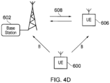
- Figure 4D illustrates a fourth embodiment of a telecommunications system according to the present disclosure.
- the UE 600 may connect to the core network via either a base station 602 or a relay UE 606, the relay UE 606 being in communication with the base station 602 as indicated by uplink/downlink arrows 608.
- the base station 602 and the relay UE 606 are the network nodes available to the UE 600 to connect to the core network.
- the UE 600 is configured to communicate with the base station 602 over a first radio path (the first radio path being a direct radio path between the UE 600 and base station 602) or over a second radio path (the second radio path being a relayed radio path comprising a first relayed radio path element between the UE 600 and the relay UE 606 and a second relayed radio path element between the relay UE 606 and the base station 602).
- the UE 600 transmits the beacon signalling B.
- the beacon signalling is received and measured at each of the base station 602 and the relay UE 606.
- the controller controls either the base station 602 or relay UE 606 to perform communication with the UE 600 so as to allow the UE 600 to communicate with the core network.
- this embodiment of the disclosure is similar to that schematically shown in Figure 4B , but with the first base station 602 and the second base station 604 being the same base station.
- the controller (or controller element) 700 selects which one of the network nodes is to perform communication with the UE 600 so as to allow the UE 600 to communicate with the core network on the basis of the measurements of the beacon signalling B made by each of the network nodes positioned so as to receive the beacon signalling B.
- the selected network node may be referred to as the serving node.
- the controller receives a measurement report indicating the measurement of the beacon signalling B from each node at which the beacon signalling B is received and measured, and determines the serving node on the basis of these measurements.
- the network node which is determined to be the serving node then establishes communication with the UE 600 on the basis of control signalling transmitted to the selected serving node from the controller 700.
- the controller may be comprised within any suitable element of the telecommunications network which is able to establish a communication path with the network nodes for the transmission of beacon signalling measurement reports and the transmission of control signalling.
- the controller may be comprised as part of a base station or as part of the core network.
- any suitable characteristic of the beacon signalling B which is indicative of the radio channel conditions associated with the radio path between the UE 600 and each respective network node may be measured by the network nodes and reported to the controller.
- the measured characteristic may be the signal strength or quality of the beacon signalling, and the controller may control the node which measures the highest signal strength or quality of the beacon signalling to be the serving node.
- the signal strength or quality of a known sequence of reference symbols of the beacon signalling could be the measured characteristic.
- the controller may also take other information into account in the selection of the serving node, such as the downlink coverage of the network node (for example, even if a network node measures the highest signal strength from the mobile device, the cell may not be suitable due to the overall path loss between the device and the network node), the load at each node or Quality of Service (QoS) requirements.
- QoS Quality of Service
- each of the first base station 602 and second base station 604 may be any suitable kind of base station, including a macro cell base station, pico cell base station or femto cell base station, for example.
- FIG. 5 A process by which serving nodes are selected and reselected according to an embodiment of the present disclosure is illustrated in Figure 5 .
- signalling is performed between a controller 700, a first network node 702, a second network node 704 and a UE 600.
- the controller 700 is a controller for selecting one of the first and second network nodes 702, 704 as a serving node for performing communication with the UE 600 (as described above).
- Each of the first and second network nodes 702, 704 may be, for example, a base station or relay node as described with reference to Figures 4A-D . It will be appreciated that if at least one of the first and second network nodes 702, 704 is a relay node, then signalling between the relay node and the controller 700 will occur via the respective base station with which the relay node performs communication.
- step 1 the controller 700 configures the first and second network nodes 702, 704 to perform measurements of the beacon signalling transmitted by the UE 600.
- step 2 the UE 600, which is currently in a first, idle mode in which it does not perform communication with any network node, transmits beacon signalling.
- step 3 the beacon signalling transmitted by the UE 600 is measured by each of the network nodes 702, 704 and the measurements are reported to the controller 700.
- step 4 the controller then configures the first network node 702 to be the serving node (or active node).
- the first network node 702 may be selected as the active node by the controller 700 because a measurement of the signal quality of the beacon signalling is higher at the first network node 702 than at the second network node 704, for example.
- step 5 communication is established between the UE 600 and the first network node 702 and the UE 600 transitions to a second, connected mode.
- a temporary identifier for addressing the UE 600 is established by a suitable element of the network (such as the controller 700 or the first network node 702).
- This temporary identifier allows resources scheduled to the UE 600 in the uplink/downlink physical radio channels to be identified by the UE and/or network node (the temporary identifier therefore being similar to the Radio Network Temporary Identifier (RNTI) used in existing Long Term Evolution (LTE) networks, for example).
- RTI Radio Network Temporary Identifier
- uplink and downlink communication is performed between the UE 600 and the first network node 702. This may occur over uplink and downlink channels which are shared between different network nodes, as described in more detail below.
- the UE 600 continues to transmit beacon signalling so as to allow further measurement of the beacon signalling by each of the network nodes 702, 704 and monitoring of the beacon signalling measurements by the controller 700.
- the reporting of the beacon signal measurements to the controller 700 by each of the first and second network nodes 702, 704 is shown in step 8.
- the controller 700 determines whether the first network node 702 is still the most suitable serving node or whether the second network node 704 would now be a more suitable serving node. This may include, for example, comparing the measurement of the beacon signalling at each of the first and second network nodes, and determining the network node with the most favourable measurement (for example, the network node with the highest signal quality measurement of the beacon signalling) as the most suitable serving node.
- the controller 700 performs a handover operation from the current serving node to the newly determined most suitable serving node.
- the second network node 704 is determined to be the most suitable serving node in step 9, and therefore the controller 700 controller deactivates the first network node 702 as the current serving node and activates the second network node 704 to become the serving node (or active node).
- the most suitable network node may change from being the first network node 702 to the second network node 704 if, for example, the UE 600 moves away from the first network node 702 and towards the second network node 704, for example.
- uplink and downlink communication is performed between the UE 600 and the second network node 704 over the shared uplink and downlink channels.
- an initial connection may be established between a UE 600 and a network node on the basis of beacon signalling from the UE 600, and furthermore, the network node which performs communication with the UE 600 may be changed on the basis of beacon signalling from the UE 600.
- a reliable connection between the UE 600 and the network can therefore be established and maintained on the basis of the beacon signalling from the UE 600.
- the UE 600 therefore does not need to perform the downlink signal measurements of conventional telecommunications systems, thus reducing power consumption at the UE 600 and allowing the UE 600 to have a simpler, lower cost design, and reducing the control signalling overhead thus improving handover reliability and network capacity.
- the beacon signal transmitted by the UE 600 is an uplink signal which may be, for example, transmitted on a shared physical channel.
- the beacon signal has a characteristic (such as signal strength or signal quality of a known sequence of reference symbols, for example) which is measurable by each network node and which is indicative of radio channel conditions associated with the radio path between the UE 600 and each network node.
- the beacon signal also allows the UE 600 to be uniquely identified by the network (for example, the beacon signal transmitted by the UE 600 may comprise an identifier which uniquely identifies the UE 600 over other UEs).
- the beacon signal is transmitted over a shared physical channel over a single predetermined carrier frequency.
- this allows the hardware and/or software resources in the UE which implement the beacon signalling to be simple in design (and therefore reliable and low cost) and to have low power consumption.
- the beacon signalling transmitted by the UE 600 is transmitted periodically so as to reduce power consumption at the UE.
- the time period between each periodic beacon signalling transmission may be a first time period
- the time period between each periodic beacon signalling transmission may be a second time period, the second time period being different to the first time period.
- the second time period may be shorter than the first time period so as to provide periodic beacon signalling which is less frequent in the idle mode (thus allowing further reduced power consumption whilst still providing beacon signalling sufficient to allow connection of the UE with the core network) and more frequent in the connected mode (thus allowing a reliable connection of the UE with the core network to be maintained).
- the power of the transmitted beacon signalling may be reduced once the UE is connected with a network node in the connected mode, for example based on power control feedback.
- the controller 700 performs initial selection of the serving node on the basis of the beacon signal measurements reported by each network node and also controls subsequent handover between network nodes on the basis of these beacon signal measurements.
- the controller 700 may also take into account other factors when selecting the most suitable serving node (either as an initial network node selection or when performing handover between network nodes), such as downlink coverage of the network node (for example, even if a network node measures the highest signal strength from the mobile device, the cell may not be suitable due to the overall path loss between the device and the network node), the load at each network node or Quality of Service (QoS) requirements (as mentioned above).
- QoS Quality of Service
- the synchronisation may be performed by, for example, either the selected node adjusting its downlink timing according to the timing of the UE (as determined by the uplink beacon signalling from the UE) or by the selected node sending a downlink synchronisation signal to the UE so that the UE can adjust its timing.
- the uplink/downlink scheduling is carried out on the basis of the temporary identifier established for addressing the UE 600 when it first connects to the network.
- the same physical downlink and uplink channels may be shared by different network nodes.
- the controller 700 on the basis of the beacon signal measurements reported by the network nodes, selects a new serving node, handover from the current serving node to the new serving node simply requires the temporary identifier of the UE 600 to be transferred from the current serving node to the new serving node via an appropriate backhaul interface.
- Scheduling of resources on the shared physical uplink/downlink channels then continues on the basis of the temporary identifier of the UE 600 as before, and the UE 600 need not perform any further operations so as to allow the handover to be completed other than timing synchronisation with the new serving node.
- the controller 700 and/or the network nodes may use resource mapping (similar to that used in LTE, for example) so as to ensure that the same resource element in the shared physical uplink/down channels is not used by more than one network node at any one time.
- the backhaul interface (not shown) between nodes (over which the temporary identifier of the UE 600 is transferred during handover) may be a wired interface (for handover between base stations such as shown in Figure 4A , for example) or a wireless interface (for handover between a relay node and a base station with which that relay node is performing communication such as shown in Figure 4D , for example).
- the backhaul interface may also comprise both a wired and wireless interface (for handover between a relay node and a base station with which that relay node is not performing communication such as shown in Figure 4B , for example).
Landscapes
- Engineering & Computer Science (AREA)
- Computer Networks & Wireless Communication (AREA)
- Signal Processing (AREA)
- Mobile Radio Communication Systems (AREA)
Claims (9)
- Drahtlos-Telekommunikationssystem, umfassend:ein Steuerungselement (700);eine erste Basisstation (602) und eine zweite Basisstation (604); undein Endgerät (600), das in der Lage ist, mit der ersten Basisstation über einen ersten Funkpfad zu kommunizieren und mit der zweiten Basisstation über einen zweiten Funkpfad zu kommunizieren;wobei das Steuerungselement dafür ausgelegt ist, eine von der ersten Basisstation und der zweiten Basisstation zum Fungieren als bedienende Basisstation für das Endgerät auf der Grundlage von mindestens einem Messbericht auszuwählen, der Messungen von Bakensignalisierung angibt, die vom Endgerät gesendet wird, wobei die Messungen eine Angabe von Funkkanalbedingungen bereitstellen, die dem ersten Funkpfad und dem zweiten Funkpfad zugeordnet sind; undwobei die Kommunikation zwischen dem Endgerät und einer der Basisstationen über einen Relaisknoten (606) erfolgt, derart, dass der entsprechende Funkpfad ein weitergeleiteter Funkpfad ist, der ein erstes weitergeleitetes Funkpfadelement zwischen dem Endgerät und dem Relaisknoten und ein zweites weitergeleitetes Funkpfadelement zwischen dem Relaisknoten und der entsprechenden Basisstation umfasst, und wobei die Messungen von Bakensignalisierung für den weitergeleiteten Funkpfad Messungen von Funkkanalbedingungen, die durch den Relaisknoten durchgeführt werden, sind, die dem ersten weitergeleiteten Funkpfadelement zugeordnet sind.
- Drahtlos-Telekommunikationssystem nach Anspruch 1, wobei das Endgerät dafür ausgelegt ist, die Bakensignalisierung periodisch zu senden.
- Drahtlos-Telekommunikationssystem nach Anspruch 2, wobei das Endgerät dafür ausgelegt ist, folgende Modi aufzuweisen:einen ersten Modus, in dem weder die erste noch die zweite Basisstation als bedienende Basisstation fungiert und in dem die Zeitspanne zwischen jeder periodischen Bakensignalübertragung eine erste Zeitspanne ist; undeinen zweiten Modus, in dem eine von der ersten und der zweiten Basisstation als bedienende Basisstation fungiert und in dem die Zeitspanne zwischen jeder periodischen Bakensignalübertragung eine zweite Zeitspanne ist, wobei die zweite Zeitspanne von der ersten Zeitspanne verschieden ist.
- Drahtlos-Telekommunikationssystem nach Anspruch 1, wobei:
wenn das Steuerungselement die erste Basisstation zum Fungieren als die bedienende Basisstation für das Endgerät ausgewählt hat, das Steuerelement für folgende Vorgänge ausgelegt ist:Bestimmen, auf der Grundlage weiterer Messungen der vom Endgerät gesendeten Bakensignalisierung, ob die zweite Basisstation besser geeignet geworden ist, als die bedienende Basisstation zu fungieren, als die erste Basisstation; undwenn bestimmt wird, dass die zweite Basisstation besser geeignet geworden ist, als die bedienende Basisstation zu fungieren, als die erste Basisstation, Durchführen eines Übergabevorgangs zum Auswählen der zweiten Basisstation zum Fungieren als die bedienende Basisstation. - Drahtlos-Telekommunikationssystem nach Anspruch 4, wobei:jede von der ersten Basisstation und der zweiten Basisstation dafür ausgelegt ist, den gleichen physischen Uplink-Funkkanal und den gleichen physischen Downlink-Funkkanal zur Kommunikation mit dem Endgerät zu verwenden, wenn sie als die bedienende Basisstation fungiert, wobei Ressourcen des physischen Uplink-Funkkanals und des physischen Downlink-Funkkanals für das Endgerät auf der Grundlage einer für das Endgerät eingerichteten temporären Kennung geplant werden; undwenn die Steuerung den Übergabevorgang zum Auswählen der zweiten Basisstation zum Fungieren als die bedienende Basisstation durchführt, die Steuereinheit dafür ausgelegt ist, die erste Basisstation zum Übertragen der temporäre Kennung an die zweite Basisstation zu steuern.
- Verfahren zum Betreiben eines Drahtlos-Telekommunikationssystems, das eine erste Basisstation (602), eine zweite Basisstation (604) und ein Endgerät (600) umfasst, das in der Lage ist, mit der ersten Basisstation über einen ersten Funkpfad zu kommunizieren und mit der zweiten Basisstation über einen zweiten Funkpfad zu kommunizieren, wobei das Verfahren umfasst:Auswählen einer von der ersten Basisstation und der zweiten Basisstation zum Fungieren als bedienende Basisstation für das Endgerät auf der Grundlage von mindestens einem Messbericht, der Messungen von Bakensignalisierung angibt, die vom Endgerät gesendet wird, wobei die Messungen eine Angabe von Funkkanalbedingungen bereitstellen, die dem ersten Funkpfad und dem zweiten Funkpfad zugeordnet sind;wobei die Kommunikation zwischen dem Endgerät und einer der Basisstationen über einen Relaisknoten (606) erfolgt, derart, dass der entsprechende Funkpfad ein weitergeleiteter Funkpfad ist, der ein erstes weitergeleitetes Funkpfadelement zwischen dem Endgerät und dem Relaisknoten und ein zweites weitergeleitetes Funkpfadelement zwischen dem Relaisknoten und der entsprechenden Basisstation umfasst, und wobei die Messungen von Bakensignalisierung für den weitergeleiteten Funkpfad Messungen von Funkkanalbedingungen, die durch den Relaisknoten durchgeführt werden, sind, die dem ersten weitergeleiteten Funkpfadelement zugeordnet sind.
- Steuerungselement (700); wobei das Steuerungselement zur Verwendung in einem Drahtlos-Telekommunikationssystem bestimmt ist, wobei das Drahtlos-Telekommunikationssystem umfasst: eine erste Basisstation (602) und eine zweite Basisstation (604); und ein Endgerät (600), das in der Lage ist mit der ersten Basisstation über einen ersten Funkpfad zu kommunizieren und mit der zweiten Basisstation über einen zweiten Funkpfad zu kommunizieren; wobei das Steuerungselement dafür ausgelegt ist, von der ersten und der zweiten Basisstation Messberichte zu empfangen, die Messungen von Bakensignalisierung angeben, die vom Endgerät gesendet wird, wobei die Messungen eine Angabe über Funkkanalbedingungen bereitstellen, die dem ersten Funkpfad und dem zweiten Funkpfad zugeordnet sind, und auf der Grundlage der Messberichte eine von der ersten Basisstation und der zweiten Basisstation zum Fungieren als bedienende Basisstation für das Endgerät auszuwählen; wobei die Kommunikation zwischen dem Endgerät und einer der Basisstationen über einen Relaisknoten (606) erfolgt, derart, dass der entsprechende Funkpfad ein weitergeleiteter Funkpfad ist, der ein erstes weitergeleitetes Funkpfadelement zwischen dem Endgerät und dem Relaisknoten und ein zweites weitergeleitetes Funkpfadelement zwischen dem Relaisknoten und der entsprechenden Basisstation umfasst, und wobei die Messungen von Bakensignalisierung für den weitergeleiteten Funkpfad Messungen von Funkkanalbedingungen, die durch den Relaisknoten durchgeführt werden, sind, die dem ersten weitergeleiteten Funkpfadelement zugeordnet sind.
- Verfahren zum Betreiben eines Steuerungselementes (700); wobei das Steuerungselement zur Verwendung in einem Drahtlos-Telekommunikationssystem bestimmt ist, wobei das Drahtlos-Telekommunikationssystem umfasst:eine erste Basisstation (602) und eine zweite Basisstation (604); und ein Endgerät (600), das in der Lage ist mit der ersten Basisstation über einen ersten Funkpfad zu kommunizieren und mit der zweiten Basisstation über einen zweiten Funkpfad zu kommunizieren; wobei das Verfahren umfasst: Empfangen, von der ersten und der zweiten Basisstation, von Messberichten, die Messungen von Bakensignalisierung angeben, die vom Endgerät gesendet wird, wobei die Messungen eine Angabe über Funkkanalbedingungen bereitstellen, die dem ersten Funkpfad und dem zweiten Funkpfad zugeordnet sind, und Auswählen, auf der Grundlage der Messberichte, einer von der ersten Basisstation und der zweiten Basisstation zum Fungieren als bedienende Basisstation für das Endgerät;wobei die Kommunikation zwischen dem Endgerät und einer der Basisstationen über einen Relaisknoten (606) erfolgt, derart, dass der entsprechende Funkpfad ein weitergeleiteter Funkpfad ist, der ein erstes weitergeleitetes Funkpfadelement zwischen dem Endgerät und dem Relaisknoten und ein zweites weitergeleitetes Funkpfadelement zwischen dem Relaisknoten und der entsprechenden Basisstation umfasst, und wobei die Messungen von Bakensignalisierung für den weitergeleiteten Funkpfad Messungen von Funkkanalbedingungen, die durch den Relaisknoten durchgeführt werden, sind, die dem ersten weitergeleiteten Funkpfadelement zugeordnet sind.
- Schaltungsanordnung für ein Steuerungselement (700); wobei das Steuerungselement zur Verwendung in einem Drahtlos-Telekommunikationssystem bestimmt ist, wobei das Drahtlos-Telekommunikationssystem umfasst:eine erste Basisstation (602) und eine zweite Basisstation (604); und ein Endgerät (600), das in der Lage ist mit der ersten Basisstation über einen ersten Funkpfad zu kommunizieren und mit der zweiten Basisstation über einen zweiten Funkpfad zu kommunizieren; wobei die Schaltungsanordnung dafür ausgelegt ist, das Steuerungselement zum Empfangen, von der ersten und der zweiten Basisstation, von Messberichten zu steuern, die Messungen von Bakensignalisierung angeben, die vom Endgerät gesendet wird, wobei die Messungen eine Angabe über Funkkanalbedingungen bereitstellen, die dem ersten Funkpfad und dem zweiten Funkpfad zugeordnet sind, und zum Auswählen, auf der Grundlage der Messberichte, einer von der ersten Basisstation und der zweiten Basisstation zum Fungieren als bedienende Basisstation für das Endgerät zu steuern;wobei die Kommunikation zwischen dem Endgerät und einer der Basisstationen über einen Relaisknoten (606) erfolgt, derart, dass der entsprechende Funkpfad ein weitergeleiteter Funkpfad ist, der ein erstes weitergeleitetes Funkpfadelement zwischen dem Endgerät und dem Relaisknoten und ein zweites weitergeleitetes Funkpfadelement zwischen dem Relaisknoten und der entsprechenden Basisstation umfasst, und wobei die Messungen von Bakensignalisierung für den weitergeleiteten Funkpfad Messungen von Funkkanalbedingungen, die durch den Relaisknoten durchgeführt werden, sind, die dem ersten weitergeleiteten Funkpfadelement zugeordnet sind.
Applications Claiming Priority (2)
| Application Number | Priority Date | Filing Date | Title |
|---|---|---|---|
| EP15173562 | 2015-06-24 | ||
| PCT/EP2016/063378 WO2016206998A1 (en) | 2015-06-24 | 2016-06-10 | Node reselection determined by the network on received ue beacon signaling |
Publications (2)
| Publication Number | Publication Date |
|---|---|
| EP3314943A1 EP3314943A1 (de) | 2018-05-02 |
| EP3314943B1 true EP3314943B1 (de) | 2023-07-26 |
Family
ID=53487267
Family Applications (1)
| Application Number | Title | Priority Date | Filing Date |
|---|---|---|---|
| EP16732523.2A Active EP3314943B1 (de) | 2015-06-24 | 2016-06-10 | Knotenneuauswahl über einen weiterleitenden knoten und basierend auf empfangener ue-bakensignalisierung |
Country Status (3)
| Country | Link |
|---|---|
| US (1) | US10743230B2 (de) |
| EP (1) | EP3314943B1 (de) |
| WO (1) | WO2016206998A1 (de) |
Families Citing this family (8)
| Publication number | Priority date | Publication date | Assignee | Title |
|---|---|---|---|---|
| CN105900377B (zh) | 2014-09-02 | 2019-10-18 | 华为技术有限公司 | 一种传输数据的方法和设备 |
| WO2017198394A1 (en) | 2016-05-20 | 2017-11-23 | Sony Corporation | Telecommunications apparatus and methods |
| EP3497973B1 (de) | 2016-08-11 | 2023-09-13 | Sony Group Corporation | Telekommunikationsvorrichtung und verfahren zur auslösung eines übergabebeurteilungsverfahrens |
| EP3515119B1 (de) * | 2016-09-22 | 2020-11-04 | Guangdong Oppo Mobile Telecommunications Corp., Ltd. | Verwaltung durch eine erstes netzgerät von einer verbindung zwischen einem endgerät und einem zweiten netzgerät gemäss der verbindungsqualität |
| EP3524000A1 (de) | 2016-10-07 | 2019-08-14 | Sony Corporation | Benutzergerät und basisstation |
| US11277784B2 (en) * | 2018-01-11 | 2022-03-15 | Sony Corporation | Wireless communications device and method |
| US11297669B2 (en) * | 2018-11-02 | 2022-04-05 | Samsung Electronics Co., Ltd. | Method for transmitting control signaling in relay network, configuration method and device |
| WO2020258085A1 (en) * | 2019-06-26 | 2020-12-30 | Telefonaktiebolaget Lm Ericsson (Publ) | Method and apparatus for information sharing |
Citations (2)
| Publication number | Priority date | Publication date | Assignee | Title |
|---|---|---|---|---|
| GB2493183A (en) * | 2011-07-27 | 2013-01-30 | Renesas Mobile Corp | Determining, from an uplink beacon signal, characteristics of a radio path and timing information and storing this information in a shared database |
| US8548376B2 (en) * | 2009-11-05 | 2013-10-01 | Lg Electronics Inc. | Operation method and apparatus of relay and base station |
Family Cites Families (12)
| Publication number | Priority date | Publication date | Assignee | Title |
|---|---|---|---|---|
| US8208936B2 (en) | 2008-09-04 | 2012-06-26 | Telefonaktiebolaget Lm Ericsson (Publ) | Methods and apparatus for improving cell-edge data throughput in a wireless communications system |
| CN102349322A (zh) * | 2009-03-18 | 2012-02-08 | 富士通株式会社 | 中继站、中继方法、基站、通信方法以及通信系统 |
| US8559957B2 (en) | 2010-01-28 | 2013-10-15 | Qualcomm Incorporated | Method and apparatus for biasing a handoff decision based on a blackhaul link |
| KR101750369B1 (ko) * | 2010-11-18 | 2017-06-23 | 삼성전자 주식회사 | 분산 안테나를 사용하는 이동 통신 시스템에서 상향 링크 전력 제어 방법 및 장치 |
| CN103563442B (zh) | 2011-04-11 | 2018-05-29 | 诺基亚通信公司 | 在切换中使用的方法和装置 |
| US8774847B2 (en) * | 2011-07-27 | 2014-07-08 | Broadcom Corporation | Cellular radio path measurement and reporting |
| WO2013167807A1 (en) | 2012-05-11 | 2013-11-14 | Nokia Corporation | Setup and maintenance framework for flexible time division duplex operation in heterogeneous network |
| US20140171062A1 (en) * | 2012-12-19 | 2014-06-19 | Telefonaktiebolaget L M Ericsson (Publ) | Wireless Devices, Network Node and Methods for Handling Relay Assistance in a Wireless Communications Network |
| US9973980B2 (en) * | 2013-03-06 | 2018-05-15 | Qualcomm Incorporated | Communications methods and apparatus that facilitate handover decisions and related measurements |
| CN105594293B (zh) * | 2013-09-27 | 2019-07-26 | 瑞典爱立信有限公司 | 设备到设备(d2d)控制信息中继的方法、节点及设备 |
| WO2015119538A1 (en) * | 2014-02-04 | 2015-08-13 | Telefonaktiebolaget L M Ericsson (Publ) | Methods, wireless device, base station and candidate relay station for supporting d2d communication over relay |
| WO2016128213A1 (en) | 2015-02-11 | 2016-08-18 | Sony Corporation | Communications device, infrastructure equipment, and methods |
-
2016
- 2016-06-10 US US15/571,209 patent/US10743230B2/en active Active
- 2016-06-10 EP EP16732523.2A patent/EP3314943B1/de active Active
- 2016-06-10 WO PCT/EP2016/063378 patent/WO2016206998A1/en active Application Filing
Patent Citations (2)
| Publication number | Priority date | Publication date | Assignee | Title |
|---|---|---|---|---|
| US8548376B2 (en) * | 2009-11-05 | 2013-10-01 | Lg Electronics Inc. | Operation method and apparatus of relay and base station |
| GB2493183A (en) * | 2011-07-27 | 2013-01-30 | Renesas Mobile Corp | Determining, from an uplink beacon signal, characteristics of a radio path and timing information and storing this information in a shared database |
Also Published As
| Publication number | Publication date |
|---|---|
| WO2016206998A1 (en) | 2016-12-29 |
| EP3314943A1 (de) | 2018-05-02 |
| US20180270730A1 (en) | 2018-09-20 |
| US10743230B2 (en) | 2020-08-11 |
Similar Documents
| Publication | Publication Date | Title |
|---|---|---|
| EP3314943B1 (de) | Knotenneuauswahl über einen weiterleitenden knoten und basierend auf empfangener ue-bakensignalisierung | |
| KR101871620B1 (ko) | 무선 통신 시스템에서 이동국 및 기지국을 작동시키는 방법, 무선 통신 시스템의 이동국 및 기지국 | |
| US9521603B2 (en) | Communication control method, base station, and user terminal | |
| US9049671B2 (en) | Radio communication system, radio base station, and power control method | |
| US9674842B2 (en) | Communication control method, base station, and user terminal | |
| US20130072212A1 (en) | Radio communication system, radio base station, and communication control method | |
| EP3432678B1 (de) | Vorrichtung und verfahren zur konfiguration eines sekundären knotens und berichterstattung in dualer konnektivität | |
| US8812010B2 (en) | Radio communication system, radio base station, and communication control method | |
| CN112106394A (zh) | 用于被配置为在第一小区中在重叠时间内使用第一操作模式和第二操作模式进行操作的无线设备的无线电链路监视(rlm)过程 | |
| WO2015007122A1 (zh) | 干扰处理方法和基站 | |
| CN104541538A (zh) | 无线电通信系统、无线电终端、无线电站和通信控制方法 | |
| CN103096375B (zh) | 天线系统及其中接收功率的报告方法 | |
| EP3029978A1 (de) | Drahtlose basisstation, benutzerendgerät und drahtloskommunikationsverfahren | |
| US9467916B2 (en) | Incremental compensation communication station coverage area expansion utilizing available frequency channels | |
| EP3619951B1 (de) | Verfahren zur verwendung einer kurzsignalidentität in der kommunikation zwischen einem funkendgerät und einem funkzugangsknoten, funkendgerät und funkzugangsknoten | |
| US9843972B2 (en) | Incremental compensation cell expansion during communications system radio coverage reconfiguration | |
| CN110383882B (zh) | 用于适配改变无线电连接的过程的ue、第一和第二无线电控制节点(rcn)以及其中的方法 | |
| US11558765B2 (en) | Control information based activation of measurement reporting configurations | |
| US20230110952A1 (en) | Beam-switching for user equipment in inactive state with configured grants | |
| EP2582180A1 (de) | Funkkommunikationssystem, funkbasisstation, funkendgeräte und kommunikationssteuerverfahren | |
| EP3874802A1 (de) | Begrenzter zellensuchmodus für drahtlose geräte | |
| CN114557029A (zh) | 同时切换和载波聚合配置 | |
| JP7314439B1 (ja) | ユーザ装置、ノード、及び通信方法 | |
| US9191901B2 (en) | Radio base station and power control method | |
| KR20150015652A (ko) | 상향링크 주파수 변경 장치 및 방법 |
Legal Events
| Date | Code | Title | Description |
|---|---|---|---|
| STAA | Information on the status of an ep patent application or granted ep patent |
Free format text: STATUS: THE INTERNATIONAL PUBLICATION HAS BEEN MADE |
|
| PUAI | Public reference made under article 153(3) epc to a published international application that has entered the european phase |
Free format text: ORIGINAL CODE: 0009012 |
|
| STAA | Information on the status of an ep patent application or granted ep patent |
Free format text: STATUS: REQUEST FOR EXAMINATION WAS MADE |
|
| 17P | Request for examination filed |
Effective date: 20171202 |
|
| AK | Designated contracting states |
Kind code of ref document: A1 Designated state(s): AL AT BE BG CH CY CZ DE DK EE ES FI FR GB GR HR HU IE IS IT LI LT LU LV MC MK MT NL NO PL PT RO RS SE SI SK SM TR |
|
| AX | Request for extension of the european patent |
Extension state: BA ME |
|
| DAV | Request for validation of the european patent (deleted) | ||
| DAX | Request for extension of the european patent (deleted) | ||
| STAA | Information on the status of an ep patent application or granted ep patent |
Free format text: STATUS: EXAMINATION IS IN PROGRESS |
|
| 17Q | First examination report despatched |
Effective date: 20190614 |
|
| STAA | Information on the status of an ep patent application or granted ep patent |
Free format text: STATUS: EXAMINATION IS IN PROGRESS |
|
| RAP3 | Party data changed (applicant data changed or rights of an application transferred) |
Owner name: SONY GROUP CORPORATION Owner name: SONY EUROPE LIMITED |
|
| RIC1 | Information provided on ipc code assigned before grant |
Ipc: H04W 36/00 20090101AFI20210628BHEP Ipc: H04W 24/10 20090101ALN20210628BHEP Ipc: H04W 88/04 20090101ALN20210628BHEP |
|
| STAA | Information on the status of an ep patent application or granted ep patent |
Free format text: STATUS: EXAMINATION IS IN PROGRESS |
|
| RIC1 | Information provided on ipc code assigned before grant |
Ipc: H04W 88/04 20090101ALN20221215BHEP Ipc: H04W 24/10 20090101ALN20221215BHEP Ipc: H04W 36/00 20090101AFI20221215BHEP |
|
| GRAP | Despatch of communication of intention to grant a patent |
Free format text: ORIGINAL CODE: EPIDOSNIGR1 |
|
| STAA | Information on the status of an ep patent application or granted ep patent |
Free format text: STATUS: GRANT OF PATENT IS INTENDED |
|
| RIC1 | Information provided on ipc code assigned before grant |
Ipc: H04W 88/04 20090101ALN20230118BHEP Ipc: H04W 24/10 20090101ALN20230118BHEP Ipc: H04W 36/00 20090101AFI20230118BHEP |
|
| INTG | Intention to grant announced |
Effective date: 20230202 |
|
| GRAS | Grant fee paid |
Free format text: ORIGINAL CODE: EPIDOSNIGR3 |
|
| GRAA | (expected) grant |
Free format text: ORIGINAL CODE: 0009210 |
|
| STAA | Information on the status of an ep patent application or granted ep patent |
Free format text: STATUS: THE PATENT HAS BEEN GRANTED |
|
| AK | Designated contracting states |
Kind code of ref document: B1 Designated state(s): AL AT BE BG CH CY CZ DE DK EE ES FI FR GB GR HR HU IE IS IT LI LT LU LV MC MK MT NL NO PL PT RO RS SE SI SK SM TR |
|
| REG | Reference to a national code |
Ref country code: GB Ref legal event code: FG4D |
|
| REG | Reference to a national code |
Ref country code: CH Ref legal event code: EP |
|
| REG | Reference to a national code |
Ref country code: IE Ref legal event code: FG4D |
|
| REG | Reference to a national code |
Ref country code: DE Ref legal event code: R096 Ref document number: 602016081355 Country of ref document: DE |
|
| REG | Reference to a national code |
Ref country code: LT Ref legal event code: MG9D |
|
| REG | Reference to a national code |
Ref country code: NL Ref legal event code: MP Effective date: 20230726 |
|
| REG | Reference to a national code |
Ref country code: AT Ref legal event code: MK05 Ref document number: 1593390 Country of ref document: AT Kind code of ref document: T Effective date: 20230726 |
|
| PG25 | Lapsed in a contracting state [announced via postgrant information from national office to epo] |
Ref country code: NL Free format text: LAPSE BECAUSE OF FAILURE TO SUBMIT A TRANSLATION OF THE DESCRIPTION OR TO PAY THE FEE WITHIN THE PRESCRIBED TIME-LIMIT Effective date: 20230726 |
|
| PG25 | Lapsed in a contracting state [announced via postgrant information from national office to epo] |
Ref country code: GR Free format text: LAPSE BECAUSE OF FAILURE TO SUBMIT A TRANSLATION OF THE DESCRIPTION OR TO PAY THE FEE WITHIN THE PRESCRIBED TIME-LIMIT Effective date: 20231027 |
|
| PG25 | Lapsed in a contracting state [announced via postgrant information from national office to epo] |
Ref country code: IS Free format text: LAPSE BECAUSE OF FAILURE TO SUBMIT A TRANSLATION OF THE DESCRIPTION OR TO PAY THE FEE WITHIN THE PRESCRIBED TIME-LIMIT Effective date: 20231126 |
|
| PG25 | Lapsed in a contracting state [announced via postgrant information from national office to epo] |
Ref country code: SE Free format text: LAPSE BECAUSE OF FAILURE TO SUBMIT A TRANSLATION OF THE DESCRIPTION OR TO PAY THE FEE WITHIN THE PRESCRIBED TIME-LIMIT Effective date: 20230726 Ref country code: RS Free format text: LAPSE BECAUSE OF FAILURE TO SUBMIT A TRANSLATION OF THE DESCRIPTION OR TO PAY THE FEE WITHIN THE PRESCRIBED TIME-LIMIT Effective date: 20230726 Ref country code: PT Free format text: LAPSE BECAUSE OF FAILURE TO SUBMIT A TRANSLATION OF THE DESCRIPTION OR TO PAY THE FEE WITHIN THE PRESCRIBED TIME-LIMIT Effective date: 20231127 Ref country code: NO Free format text: LAPSE BECAUSE OF FAILURE TO SUBMIT A TRANSLATION OF THE DESCRIPTION OR TO PAY THE FEE WITHIN THE PRESCRIBED TIME-LIMIT Effective date: 20231026 Ref country code: LV Free format text: LAPSE BECAUSE OF FAILURE TO SUBMIT A TRANSLATION OF THE DESCRIPTION OR TO PAY THE FEE WITHIN THE PRESCRIBED TIME-LIMIT Effective date: 20230726 Ref country code: LT Free format text: LAPSE BECAUSE OF FAILURE TO SUBMIT A TRANSLATION OF THE DESCRIPTION OR TO PAY THE FEE WITHIN THE PRESCRIBED TIME-LIMIT Effective date: 20230726 Ref country code: IS Free format text: LAPSE BECAUSE OF FAILURE TO SUBMIT A TRANSLATION OF THE DESCRIPTION OR TO PAY THE FEE WITHIN THE PRESCRIBED TIME-LIMIT Effective date: 20231126 Ref country code: HR Free format text: LAPSE BECAUSE OF FAILURE TO SUBMIT A TRANSLATION OF THE DESCRIPTION OR TO PAY THE FEE WITHIN THE PRESCRIBED TIME-LIMIT Effective date: 20230726 Ref country code: GR Free format text: LAPSE BECAUSE OF FAILURE TO SUBMIT A TRANSLATION OF THE DESCRIPTION OR TO PAY THE FEE WITHIN THE PRESCRIBED TIME-LIMIT Effective date: 20231027 Ref country code: FI Free format text: LAPSE BECAUSE OF FAILURE TO SUBMIT A TRANSLATION OF THE DESCRIPTION OR TO PAY THE FEE WITHIN THE PRESCRIBED TIME-LIMIT Effective date: 20230726 Ref country code: AT Free format text: LAPSE BECAUSE OF FAILURE TO SUBMIT A TRANSLATION OF THE DESCRIPTION OR TO PAY THE FEE WITHIN THE PRESCRIBED TIME-LIMIT Effective date: 20230726 |
|
| PG25 | Lapsed in a contracting state [announced via postgrant information from national office to epo] |
Ref country code: PL Free format text: LAPSE BECAUSE OF FAILURE TO SUBMIT A TRANSLATION OF THE DESCRIPTION OR TO PAY THE FEE WITHIN THE PRESCRIBED TIME-LIMIT Effective date: 20230726 |
|
| PG25 | Lapsed in a contracting state [announced via postgrant information from national office to epo] |
Ref country code: ES Free format text: LAPSE BECAUSE OF FAILURE TO SUBMIT A TRANSLATION OF THE DESCRIPTION OR TO PAY THE FEE WITHIN THE PRESCRIBED TIME-LIMIT Effective date: 20230726 |
|
| PG25 | Lapsed in a contracting state [announced via postgrant information from national office to epo] |
Ref country code: SM Free format text: LAPSE BECAUSE OF FAILURE TO SUBMIT A TRANSLATION OF THE DESCRIPTION OR TO PAY THE FEE WITHIN THE PRESCRIBED TIME-LIMIT Effective date: 20230726 Ref country code: RO Free format text: LAPSE BECAUSE OF FAILURE TO SUBMIT A TRANSLATION OF THE DESCRIPTION OR TO PAY THE FEE WITHIN THE PRESCRIBED TIME-LIMIT Effective date: 20230726 Ref country code: ES Free format text: LAPSE BECAUSE OF FAILURE TO SUBMIT A TRANSLATION OF THE DESCRIPTION OR TO PAY THE FEE WITHIN THE PRESCRIBED TIME-LIMIT Effective date: 20230726 Ref country code: EE Free format text: LAPSE BECAUSE OF FAILURE TO SUBMIT A TRANSLATION OF THE DESCRIPTION OR TO PAY THE FEE WITHIN THE PRESCRIBED TIME-LIMIT Effective date: 20230726 Ref country code: DK Free format text: LAPSE BECAUSE OF FAILURE TO SUBMIT A TRANSLATION OF THE DESCRIPTION OR TO PAY THE FEE WITHIN THE PRESCRIBED TIME-LIMIT Effective date: 20230726 Ref country code: CZ Free format text: LAPSE BECAUSE OF FAILURE TO SUBMIT A TRANSLATION OF THE DESCRIPTION OR TO PAY THE FEE WITHIN THE PRESCRIBED TIME-LIMIT Effective date: 20230726 Ref country code: SK Free format text: LAPSE BECAUSE OF FAILURE TO SUBMIT A TRANSLATION OF THE DESCRIPTION OR TO PAY THE FEE WITHIN THE PRESCRIBED TIME-LIMIT Effective date: 20230726 |