EP3314731B1 - Safe assembly and installation of a flywheel - Google Patents
Safe assembly and installation of a flywheel Download PDFInfo
- Publication number
- EP3314731B1 EP3314731B1 EP16815335.1A EP16815335A EP3314731B1 EP 3314731 B1 EP3314731 B1 EP 3314731B1 EP 16815335 A EP16815335 A EP 16815335A EP 3314731 B1 EP3314731 B1 EP 3314731B1
- Authority
- EP
- European Patent Office
- Prior art keywords
- rotor
- bearing
- flywheel
- housing
- flywheel device
- Prior art date
- Legal status (The legal status is an assumption and is not a legal conclusion. Google has not performed a legal analysis and makes no representation as to the accuracy of the status listed.)
- Active
Links
- 238000009434 installation Methods 0.000 title claims description 14
- 230000033001 locomotion Effects 0.000 claims description 14
- 230000005291 magnetic effect Effects 0.000 claims description 10
- 230000007246 mechanism Effects 0.000 claims description 10
- 230000005672 electromagnetic field Effects 0.000 claims 1
- 239000003302 ferromagnetic material Substances 0.000 claims 1
- 238000000034 method Methods 0.000 description 18
- 238000013461 design Methods 0.000 description 15
- 238000004146 energy storage Methods 0.000 description 12
- 230000008569 process Effects 0.000 description 9
- 230000000712 assembly Effects 0.000 description 4
- 238000000429 assembly Methods 0.000 description 4
- 238000010586 diagram Methods 0.000 description 4
- 238000011900 installation process Methods 0.000 description 4
- 239000000463 material Substances 0.000 description 4
- 238000003860 storage Methods 0.000 description 4
- 230000008878 coupling Effects 0.000 description 3
- 238000010168 coupling process Methods 0.000 description 3
- 238000005859 coupling reaction Methods 0.000 description 3
- 229910000831 Steel Inorganic materials 0.000 description 2
- 238000005096 rolling process Methods 0.000 description 2
- 238000009987 spinning Methods 0.000 description 2
- 239000010959 steel Substances 0.000 description 2
- 238000003466 welding Methods 0.000 description 2
- 230000004913 activation Effects 0.000 description 1
- 239000000956 alloy Substances 0.000 description 1
- 229910045601 alloy Inorganic materials 0.000 description 1
- 229910052782 aluminium Inorganic materials 0.000 description 1
- XAGFODPZIPBFFR-UHFFFAOYSA-N aluminium Chemical compound [Al] XAGFODPZIPBFFR-UHFFFAOYSA-N 0.000 description 1
- 238000006243 chemical reaction Methods 0.000 description 1
- 238000010276 construction Methods 0.000 description 1
- 125000004122 cyclic group Chemical group 0.000 description 1
- 230000003247 decreasing effect Effects 0.000 description 1
- 238000009826 distribution Methods 0.000 description 1
- 230000000694 effects Effects 0.000 description 1
- 229920006351 engineering plastic Polymers 0.000 description 1
- 229910052751 metal Inorganic materials 0.000 description 1
- 239000002184 metal Substances 0.000 description 1
- 238000012986 modification Methods 0.000 description 1
- 230000004048 modification Effects 0.000 description 1
- 229920003023 plastic Polymers 0.000 description 1
- 230000036316 preload Effects 0.000 description 1
- 238000012545 processing Methods 0.000 description 1
- 230000000135 prohibitive effect Effects 0.000 description 1
- 230000003068 static effect Effects 0.000 description 1
- 239000000725 suspension Substances 0.000 description 1
- 238000012546 transfer Methods 0.000 description 1
- 238000009827 uniform distribution Methods 0.000 description 1
Images


Classifications
-
- H—ELECTRICITY
- H02—GENERATION; CONVERSION OR DISTRIBUTION OF ELECTRIC POWER
- H02K—DYNAMO-ELECTRIC MACHINES
- H02K7/00—Arrangements for handling mechanical energy structurally associated with dynamo-electric machines, e.g. structural association with mechanical driving motors or auxiliary dynamo-electric machines
- H02K7/02—Additional mass for increasing inertia, e.g. flywheels
- H02K7/025—Additional mass for increasing inertia, e.g. flywheels for power storage
-
- G—PHYSICS
- G05—CONTROLLING; REGULATING
- G05G—CONTROL DEVICES OR SYSTEMS INSOFAR AS CHARACTERISED BY MECHANICAL FEATURES ONLY
- G05G1/00—Controlling members, e.g. knobs or handles; Assemblies or arrangements thereof; Indicating position of controlling members
-
- H—ELECTRICITY
- H02—GENERATION; CONVERSION OR DISTRIBUTION OF ELECTRIC POWER
- H02K—DYNAMO-ELECTRIC MACHINES
- H02K15/00—Methods or apparatus specially adapted for manufacturing, assembling, maintaining or repairing of dynamo-electric machines
-
- H—ELECTRICITY
- H02—GENERATION; CONVERSION OR DISTRIBUTION OF ELECTRIC POWER
- H02K—DYNAMO-ELECTRIC MACHINES
- H02K15/00—Methods or apparatus specially adapted for manufacturing, assembling, maintaining or repairing of dynamo-electric machines
- H02K15/14—Casings; Enclosures; Supports
-
- H—ELECTRICITY
- H02—GENERATION; CONVERSION OR DISTRIBUTION OF ELECTRIC POWER
- H02K—DYNAMO-ELECTRIC MACHINES
- H02K7/00—Arrangements for handling mechanical energy structurally associated with dynamo-electric machines, e.g. structural association with mechanical driving motors or auxiliary dynamo-electric machines
- H02K7/003—Couplings; Details of shafts
-
- H—ELECTRICITY
- H02—GENERATION; CONVERSION OR DISTRIBUTION OF ELECTRIC POWER
- H02K—DYNAMO-ELECTRIC MACHINES
- H02K7/00—Arrangements for handling mechanical energy structurally associated with dynamo-electric machines, e.g. structural association with mechanical driving motors or auxiliary dynamo-electric machines
- H02K7/08—Structural association with bearings
- H02K7/086—Structural association with bearings radially supporting the rotor around a fixed spindle; radially supporting the rotor directly
- H02K7/088—Structural association with bearings radially supporting the rotor around a fixed spindle; radially supporting the rotor directly radially supporting the rotor directly
-
- H—ELECTRICITY
- H02—GENERATION; CONVERSION OR DISTRIBUTION OF ELECTRIC POWER
- H02K—DYNAMO-ELECTRIC MACHINES
- H02K7/00—Arrangements for handling mechanical energy structurally associated with dynamo-electric machines, e.g. structural association with mechanical driving motors or auxiliary dynamo-electric machines
- H02K7/08—Structural association with bearings
- H02K7/09—Structural association with bearings with magnetic bearings
-
- Y—GENERAL TAGGING OF NEW TECHNOLOGICAL DEVELOPMENTS; GENERAL TAGGING OF CROSS-SECTIONAL TECHNOLOGIES SPANNING OVER SEVERAL SECTIONS OF THE IPC; TECHNICAL SUBJECTS COVERED BY FORMER USPC CROSS-REFERENCE ART COLLECTIONS [XRACs] AND DIGESTS
- Y02—TECHNOLOGIES OR APPLICATIONS FOR MITIGATION OR ADAPTATION AGAINST CLIMATE CHANGE
- Y02E—REDUCTION OF GREENHOUSE GAS [GHG] EMISSIONS, RELATED TO ENERGY GENERATION, TRANSMISSION OR DISTRIBUTION
- Y02E60/00—Enabling technologies; Technologies with a potential or indirect contribution to GHG emissions mitigation
- Y02E60/16—Mechanical energy storage, e.g. flywheels or pressurised fluids
Definitions
- flywheel's bearing and suspension subsystem is designed to minimized energy losses due to friction, heat, and other loss sources.
- an energy storage flywheel system includes a flywheel assembly that is rotationally mounted in a housing assembly, and one or more actuator assemblies.
- the actuator assemblies are configured to selectively engage and disengage the flywheel assembly. When the actuator assemblies engage the flywheel assembly, the actuator assemblies provide support for, and inhibit rotation of, the flywheel assembly.
- a flywheel is coupled on both sides via an intermediate component to a stub shaft, the component having an annular portion by which it is secured to the flywheel.
- the component is a half-open cylindrical or conical body, its open end with the largest diameter being secured to the flywheel, while the other end has a stub shaft.
- the component has a shape and material where it is fixed to the flywheel to give it a radial stiffness.
- US 6 029 538 A describes a replaceable bearing cartridge assembly for use in a flywheel energy system and methods and apparatus for installing and removing the assembly.
- the assembly includes a hollow bearing cartridge, an annular bearing, and an annular bearing retaining ring.
- the cartridge has an outer surface which is mounted at a port of a flywheel housing end plate.
- the annular bearing is mounted in the cartridge and held in place by the annular bearing retaining ring.
- US 2014/055905 A1 describes an apparatus and method for unloading a rotor bearing.
- the apparatus includes an electromagnet for levitating the rotor.
- US 6 664 680 B1 describes a flywheel energy storage system having magnetic bearings that are preferably homopolar, that is, the magnetic fields do not alternate polarity around a given circumferential location.
- US 6 710 489 B1 discloses a flywheel with securing posts and a lifting mechanism that keep the flywheel secured during transportation and installation.
- a flywheel device includes a flywheel rotor for storing energy, as well as additional structures allowing the flywheel to be assembled offsite, transported safely, and installed with relatively few steps.
- the flywheel includes a rotor for storing energy, where the rotor includes a primary rotational mass and journals extending along a center axis of the rotor.
- the flywheel also includes a housing enclosing the rotor, where the housing includes a bottom plate, a top plate and side walls.
- the bottom plate and the top plate each include a hole aligned with the center axis of the rotor.
- the flywheel additionally includes multiple bearing housings substantially filling the holes of the bottom plate and the top plate that are aligned to the center axis of the rotor.
- the flywheel also includes multiple posts that are capable of physically contacting the primary rotational mass of the rotor to prevent motion of the rotor during transport of the flywheel assembly. Some or all of these posts may be repositioned or removed during installation so that the rotor can spin freely.
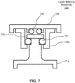
- the flywheel includes an upper bearing assembly that enables an upper bearing to support downward thrust.
- the upper bearing assembly includes a top bearing, a bearing housing, a bearing locking cap, a backup thrust bearing, and a cap.
- the backup thrust bearing receives an upward thrust load in the case of an unusual vertical movement.
- Rotor 205 is used for storing energy as kinetic energy.
- Rotor 205 is substantially rotationally symmetric around a central rotational axis 230.
- the shape of the primary rotational mass of the rotor helps ensure a nearly uniform distribution of stress due to rotational forces exerted on the rotor while it is rotating.
- Rotor 205 is coupled to two stub shafts, a lower stub shaft 227 and an upper stub shaft 229, which couple the rotor to bearings that support the rotor, while allowing for unconstrained rotation about the central axis.
- the electromagnetic rotor of a motor/alternator may also be installed on one, or both, of the stub shafts.
- stub shaft refers to a relatively short shaft that couples to one side of rotor 205. While the embodiment illustrated in FIGS. 2A-2B employs two stub-shafts, in other embodiments a single stub shaft, or two stub shafts may be used. Stub shafts 227 and 229 couple to rotor 205 via journals that extend along the center rotational axis of the rotor.
- Rotor 205 is held in place within the housing 201 by a lower bearing 207 and an upper bearing 215.
- Bearings 207, 215 also allow rotor 205 to spin freely with as little friction as possible.
- rolling ball bearings may be used.
- the bearing includes an outer ring (or race) that is physically attached to the flywheel housing 201, an inner ring (or race) that is physically attached to the shaft coupled to the rotor, and multiple rolling elements, such as balls, that allow the inner ring to spin relative to the outer ring with a low coefficient of friction.
- the bearings are confined within their respective bearing housing, and the shafts are confined within the inner race of the bearings.
- flywheel system 130 includes an offloader 213 that offloads some or all of the weight of the rotor 205. Consequently, offloader 213 reduces the load of the bearing 207, and consequently reduces the friction moment of the bearing. As such, the energy loss by the rotor due to the friction of the bearing is substantially reduced.
- the offloader 213 reduces the weight the rotor bearing 207 has to support by generating a magnetic field that attracts or repulses the rotor 205, depending upon the implementation.
- the magnetic field may be generated through circulation of an appropriately shaped current in an electromagnet, for example.
- the magnetic force experienced by the rotor 205 depends in part on the distance between the electromagnet in offloader 213 and the rotor 205. Thus, it is advantageous to have only a small distance between the electromagnet and the rotor 205. However, decreasing the distance between the offloader and the rotor increases the likelihood of the rotor striking the offloader, particularly during transport.
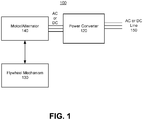
- Flywheel mechanism 130 may be assembled prior to transport to an installation site.
- flywheel mechanism 130 includes one or more of posts 203, 219 that restrict the motion of the rotor during transport.
- the posts further allow offloader 213 and rotor 205 to be placed in very close proximity without significant risk to damage to either element.
- the electromagnet in the offloader 213 can be smaller or more power efficient than it would be if it were located further away, while still producing the same effective magnetic field upon the rotor.
- the term post refers to a structural element that restricts movement of a rotor in one direction.
- only bottom posts 203 are present while in other embodiments both bottom 203 and top 219 posts are present.
- FIG. 2B is a cross sectional view of flywheel 130 during transport, according to one embodiment.
- bottom posts 203 contact rotor 205, thus restricting the downward motion of the rotor.
- top posts 219 contact rotor 205, thus restricting the upward motion of the rotor.
- the posts and bearings together restrict the lateral motion of the rotor.
- bottom posts 203 are physically attached to (or a part of) bottom plate 221 of the housing 201, and top posts 219 are removable (or at least adjustable) from the top plate 223 through holes in the top plate (not separately labeled).
- the posts may be made of any material, although materials that are strong and light weight are preferable.
- the posts may be made of inter alia aluminum, rubber, or plastic.
- top posts 219 are removed or raised up a distance, and rotor 205 is raised off of bottom posts 203 to allow rotor 205 to spin freely.
- a backing plug 211 which is threadably attached to lower bearing housing 209, is used to raise rotor 205.
- FIG. 3 is a flow diagram of a process 300 for assembling flywheel 130.
- FIGS. 4A through 4D illustrate flywheel 130 at different stages of assembly.
- Assembly process 300 starts with the bottom plate 221 of the housing 201.
- bottom posts 203 are attached to the bottom plate 221.
- the bottom posts 203 are bolted to the bottom plate 221.
- other techniques such as riveting, welding, or bonding may be used to physically attach the bottom posts 203 to the bottom plate 221. If the bottom posts 203 are movable, the bottom posts 203 are threaded into a hole of the bottom plate 221.
- the rotor may be repositioned using a coarse alignment process to properly align with the posts.
- rotor 205 may already be coupled to stub shafts 227 and 229 when the rotor is placed on the posts. In other embodiments, coupling stub shafts 227 and 229 to rotor 205 is performed as part of step 303.
- lower bearing 207, lower bearing housing 209 and backing plug 211 are physically attached to housing 201.
- lower bearing housing 209 is bolted to bottom plate 221.
- other techniques, such as riveting, welding, or bonding may be used to physically attach lower bearing housing 209 to bottom plate 221.
- Lower bearing 207 is then inserted into lower bearing housing 209, and backing plug 211 is attached to lower bearing housing 209.
- Lower bearing 207 is supported by backing plug 211 and backing plug 211 is threadably attached to lower bearing housing 209.
- an upper assembly 410 including upper bearing 215, upper bearing housing 217, upper posts 219, electromagnetic offloader 213, top plate 223, and side walls 225 of housing 201, is physically attached to the partially assembled flywheel illustrated in FIG. 4C .
- rotor 205 is cylindrical and thus in certain embodiments housing 201 is cylindrical in shape.
- side walls 225 may be a one-piece cylindrical shell.
- side walls 225 may be a single element or may be multiple attached elements which together form the sides of flywheel 130.
- the upper bearing housing 217 is physically attached to the top plate 223 and the upper bearing 215 is inserted into the upper bearing housing 217.
- the offloader 213 is physically attached to top plate 223, and the upper posts 219 are threaded into the top plate 223. Once the upper sub-assembly has been put together, the side walls 225 are physically attached to the bottom plate 221 and the top plate 223 is physically attached to the side walls 225.
- bottom plate 221, the side walls 225 and the top plate 223 of the housing 201 may be attached together using screws and/or rivets, welds, or any other known mechanism for physical attachment.
- the upper posts 219 are lowered into physical contact with the rotor.
- the upper posts may be pressed against the rotor, for example by tightening screws under an applied torque.
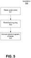
- FIG. 5 is a flow diagram of a process 500 for installing flywheel 130 once it arrives at an installation site. Essentially, these are the steps that are performed to put flywheel 130 into operation.
- FIGS. 6A-6B illustrate certain steps of process 500 for installing flywheel 130.
- top posts 210 are raised off rotor 205 so that they are no longer in physical contact with the rotor 205.
- rotor 205 is then raised off of bottom posts 203 by raising backing plug 211.
- backing plug 211 is attached using threads, threading the backing plug into the lower bearing housing 209 will raise the lower bearings 207, thereby raising the rotor 205.
- the physical distance between the rotor 205 and top 219 and bottom 203 posts after these processes are completed may vary by implementation.
- Upper bearing assembly 700 includes top bearing 701, a bearing housing 703, a bearing locking cap 705, a backup thrust bearing 707, and a cap 709.
- the flipped-bearing design also reduces the required offloader lifting force. For example, if, top bearing assembly 220 the offloader had to apply rotor weight +1000 lb, using the flipped-bearing design it applies rotor weight -1000 lb. This makes control of the electromagnet in offloader 213 easier and potentially reduces its power consumption and size.
Landscapes
- Engineering & Computer Science (AREA)
- Power Engineering (AREA)
- Manufacturing & Machinery (AREA)
- Physics & Mathematics (AREA)
- General Physics & Mathematics (AREA)
- Automation & Control Theory (AREA)
- Connection Of Motors, Electrical Generators, Mechanical Devices, And The Like (AREA)
- Magnetic Bearings And Hydrostatic Bearings (AREA)
- Manufacture Of Motors, Generators (AREA)
- Rolling Contact Bearings (AREA)
Applications Claiming Priority (2)
| Application Number | Priority Date | Filing Date | Title |
|---|---|---|---|
| US201562185441P | 2015-06-26 | 2015-06-26 | |
| PCT/US2016/039093 WO2016210176A1 (en) | 2015-06-26 | 2016-06-23 | Safe assembly and installation of a flywheel |
Publications (3)
| Publication Number | Publication Date |
|---|---|
| EP3314731A1 EP3314731A1 (en) | 2018-05-02 |
| EP3314731A4 EP3314731A4 (en) | 2019-01-16 |
| EP3314731B1 true EP3314731B1 (en) | 2021-06-16 |
Family
ID=57586466
Family Applications (1)
| Application Number | Title | Priority Date | Filing Date |
|---|---|---|---|
| EP16815335.1A Active EP3314731B1 (en) | 2015-06-26 | 2016-06-23 | Safe assembly and installation of a flywheel |
Country Status (7)
| Country | Link |
|---|---|
| EP (1) | EP3314731B1 (zh) |
| JP (1) | JP6612367B2 (zh) |
| KR (1) | KR102045340B1 (zh) |
| CN (1) | CN107820662B (zh) |
| CA (1) | CA2989308C (zh) |
| PH (1) | PH12017550141B1 (zh) |
| WO (1) | WO2016210176A1 (zh) |
Families Citing this family (3)
| Publication number | Priority date | Publication date | Assignee | Title |
|---|---|---|---|---|
| CN107608369B (zh) * | 2017-10-23 | 2023-10-03 | 沈阳航空航天大学 | 一种用于航天器姿态控制实验的模块化惯性动量轮装置 |
| US10982730B2 (en) * | 2019-03-04 | 2021-04-20 | Saint- Augustin Canada Electric Inc. | Flywheel systems and related methods |
| KR102535350B1 (ko) * | 2021-05-10 | 2023-05-26 | 에이치디현대일렉트릭 주식회사 | 발전기의 인코더용 진동저감장치 |
Citations (1)
| Publication number | Priority date | Publication date | Assignee | Title |
|---|---|---|---|---|
| US6710489B1 (en) * | 2001-08-30 | 2004-03-23 | Indigo Energy, Inc. | Axially free flywheel system |
Family Cites Families (13)
| Publication number | Priority date | Publication date | Assignee | Title |
|---|---|---|---|---|
| CH459774A (de) * | 1965-09-16 | 1968-07-15 | Oerlikon Maschf | Fahrzeug mit Rotationsenergiespeicher, Verfahren zu dessen Betrieb und Verfahren zu dessen Herstellung |
| SE323845B (zh) * | 1968-01-19 | 1970-05-11 | Atlas Copco Ab | |
| DE2754623A1 (de) * | 1977-12-08 | 1979-06-13 | Maschf Augsburg Nuernberg Ag | Schwungrad |
| JPS6064346U (ja) * | 1983-10-11 | 1985-05-07 | 三菱電機株式会社 | フライホイ−ル装置 |
| US6029538A (en) * | 1997-09-08 | 2000-02-29 | Active Power, Inc. | Replaceable bearing cartridge assembly for flywheel energy system |
| US6064121A (en) * | 1998-02-27 | 2000-05-16 | Hamilton Sundstrand Corporation | Axially compact generator set and refrigeration system employing the same |
| US6664680B1 (en) * | 2000-12-20 | 2003-12-16 | Indigo Energy, Inc. | Flywheel device with active magnetic bearings |
| US7197958B2 (en) * | 2003-08-27 | 2007-04-03 | Honeywell International, Inc. | Energy storage flywheel retention system and method |
| CN101924418A (zh) * | 2009-12-22 | 2010-12-22 | 苏州菲莱特能源科技有限公司 | 一种双圆盘结构飞轮储能系统 |
| CN201928127U (zh) * | 2010-12-03 | 2011-08-10 | 天津荣亨集团股份有限公司 | 双定子交流电机飞轮储能器 |
| CN201956795U (zh) * | 2011-02-16 | 2011-08-31 | 东南大学 | 一种飞轮储能装置 |
| KR101789616B1 (ko) * | 2012-08-23 | 2017-10-25 | 앰버 카이네틱스, 인크. | 로터 베어링을 자기적으로 언로딩하기 위한 장치 및 방법 |
| JP6461131B2 (ja) * | 2013-07-08 | 2019-01-30 | サン オーギュスタン カナダ エレクトリック インコーポレイテッド | 運動エネルギー貯蔵システムを生成するための方法 |
-
2016
- 2016-06-23 KR KR1020187002601A patent/KR102045340B1/ko active IP Right Grant
- 2016-06-23 JP JP2017567287A patent/JP6612367B2/ja active Active
- 2016-06-23 CA CA2989308A patent/CA2989308C/en active Active
- 2016-06-23 CN CN201680037320.1A patent/CN107820662B/zh active Active
- 2016-06-23 EP EP16815335.1A patent/EP3314731B1/en active Active
- 2016-06-23 WO PCT/US2016/039093 patent/WO2016210176A1/en active Application Filing
-
2017
- 2017-12-13 PH PH12017550141A patent/PH12017550141B1/en unknown
Patent Citations (1)
| Publication number | Priority date | Publication date | Assignee | Title |
|---|---|---|---|---|
| US6710489B1 (en) * | 2001-08-30 | 2004-03-23 | Indigo Energy, Inc. | Axially free flywheel system |
Also Published As
| Publication number | Publication date |
|---|---|
| EP3314731A4 (en) | 2019-01-16 |
| PH12017550141A1 (en) | 2018-06-11 |
| CA2989308C (en) | 2021-08-03 |
| EP3314731A1 (en) | 2018-05-02 |
| KR102045340B1 (ko) | 2019-11-15 |
| JP2018527518A (ja) | 2018-09-20 |
| CN107820662B (zh) | 2020-06-19 |
| PH12017550141B1 (en) | 2018-06-11 |
| KR20180021865A (ko) | 2018-03-05 |
| CA2989308A1 (en) | 2016-12-29 |
| CN107820662A (zh) | 2018-03-20 |
| WO2016210176A1 (en) | 2016-12-29 |
| JP6612367B2 (ja) | 2019-11-27 |
Similar Documents
| Publication | Publication Date | Title |
|---|---|---|
| US10240660B2 (en) | Safe assembly and installation of a flywheel | |
| US6710489B1 (en) | Axially free flywheel system | |
| EP0775382B1 (en) | An energy storage and conversion apparatus | |
| US8240231B2 (en) | Energy storage device and method of use | |
| US6388347B1 (en) | Flywheel battery system with active counter-rotating containment | |
| US6570286B1 (en) | Full magnetic bearings with increased load capacity | |
| EP3314731B1 (en) | Safe assembly and installation of a flywheel | |
| AU2002326878B2 (en) | Flywheel energy storage systems | |
| US20030192449A1 (en) | Shear force levitator and levitated ring energy storage device | |
| US20050230979A1 (en) | Direct Drive Wind Turbine | |
| US7830055B2 (en) | Hybrid touchdown bearing system | |
| US20130015825A1 (en) | Flywheel apparatus | |
| US5588754A (en) | Backup bearings for extreme speed touch down applications | |
| US6150742A (en) | Energy storage and conversion apparatus | |
| US11680624B2 (en) | Flywheel systems | |
| WO1997024536A1 (en) | Radial constrained backup bushings for re-centering of magnetic bearings | |
| Rowiński et al. | High speed electromechanical energy storage | |
| KR20130032601A (ko) | 비상베어링 및 이를 이용한 플라이휠 에너지 저장장치 | |
| JPH0215728B2 (zh) | ||
| CN117489548A (zh) | 一种应用磁悬浮轴承的风电机组的主轴系统 | |
| WO2014123507A1 (en) | High speed, compliant, planetary flywheel touchdown bearing |
Legal Events
| Date | Code | Title | Description |
|---|---|---|---|
| STAA | Information on the status of an ep patent application or granted ep patent |
Free format text: STATUS: THE INTERNATIONAL PUBLICATION HAS BEEN MADE |
|
| PUAI | Public reference made under article 153(3) epc to a published international application that has entered the european phase |
Free format text: ORIGINAL CODE: 0009012 |
|
| STAA | Information on the status of an ep patent application or granted ep patent |
Free format text: STATUS: REQUEST FOR EXAMINATION WAS MADE |
|
| 17P | Request for examination filed |
Effective date: 20171212 |
|
| AK | Designated contracting states |
Kind code of ref document: A1 Designated state(s): AL AT BE BG CH CY CZ DE DK EE ES FI FR GB GR HR HU IE IS IT LI LT LU LV MC MK MT NL NO PL PT RO RS SE SI SK SM TR |
|
| AX | Request for extension of the european patent |
Extension state: BA ME |
|
| DAV | Request for validation of the european patent (deleted) | ||
| DAX | Request for extension of the european patent (deleted) | ||
| A4 | Supplementary search report drawn up and despatched |
Effective date: 20181213 |
|
| RIC1 | Information provided on ipc code assigned before grant |
Ipc: H02K 15/14 20060101ALI20181207BHEP Ipc: G05G 1/00 20060101ALI20181207BHEP Ipc: H02K 7/08 20060101ALN20181207BHEP Ipc: H02K 7/00 20060101ALN20181207BHEP Ipc: H02K 7/09 20060101ALN20181207BHEP Ipc: H02K 7/02 20060101AFI20181207BHEP |
|
| STAA | Information on the status of an ep patent application or granted ep patent |
Free format text: STATUS: EXAMINATION IS IN PROGRESS |
|
| 17Q | First examination report despatched |
Effective date: 20200211 |
|
| STAA | Information on the status of an ep patent application or granted ep patent |
Free format text: STATUS: EXAMINATION IS IN PROGRESS |
|
| RIC1 | Information provided on ipc code assigned before grant |
Ipc: H02K 7/00 20060101ALN20200812BHEP Ipc: H02K 7/09 20060101ALN20200812BHEP Ipc: H02K 15/14 20060101ALI20200812BHEP Ipc: G05G 1/00 20060101ALI20200812BHEP Ipc: H02K 7/02 20060101AFI20200812BHEP Ipc: H02K 7/08 20060101ALN20200812BHEP |
|
| GRAP | Despatch of communication of intention to grant a patent |
Free format text: ORIGINAL CODE: EPIDOSNIGR1 |
|
| STAA | Information on the status of an ep patent application or granted ep patent |
Free format text: STATUS: GRANT OF PATENT IS INTENDED |
|
| RIC1 | Information provided on ipc code assigned before grant |
Ipc: G05G 1/00 20060101ALI20200908BHEP Ipc: H02K 7/09 20060101ALN20200908BHEP Ipc: H02K 7/00 20060101ALN20200908BHEP Ipc: H02K 7/08 20060101ALN20200908BHEP Ipc: H02K 7/02 20060101AFI20200908BHEP Ipc: H02K 15/14 20060101ALI20200908BHEP |
|
| INTG | Intention to grant announced |
Effective date: 20200922 |
|
| GRAJ | Information related to disapproval of communication of intention to grant by the applicant or resumption of examination proceedings by the epo deleted |
Free format text: ORIGINAL CODE: EPIDOSDIGR1 |
|
| STAA | Information on the status of an ep patent application or granted ep patent |
Free format text: STATUS: EXAMINATION IS IN PROGRESS |
|
| GRAS | Grant fee paid |
Free format text: ORIGINAL CODE: EPIDOSNIGR3 |
|
| STAA | Information on the status of an ep patent application or granted ep patent |
Free format text: STATUS: GRANT OF PATENT IS INTENDED |
|
| GRAP | Despatch of communication of intention to grant a patent |
Free format text: ORIGINAL CODE: EPIDOSNIGR1 |
|
| GRAJ | Information related to disapproval of communication of intention to grant by the applicant or resumption of examination proceedings by the epo deleted |
Free format text: ORIGINAL CODE: EPIDOSDIGR1 |
|
| GRAS | Grant fee paid |
Free format text: ORIGINAL CODE: EPIDOSNIGR3 |
|
| GRAS | Grant fee paid |
Free format text: ORIGINAL CODE: EPIDOSNIGR3 |
|
| INTC | Intention to grant announced (deleted) | ||
| RIC1 | Information provided on ipc code assigned before grant |
Ipc: H02K 7/02 20060101AFI20210120BHEP Ipc: H02K 15/14 20060101ALI20210120BHEP Ipc: H02K 7/08 20060101ALN20210120BHEP Ipc: H02K 7/09 20060101ALN20210120BHEP Ipc: G05G 1/00 20060101ALI20210120BHEP Ipc: H02K 7/00 20060101ALN20210120BHEP |
|
| GRAP | Despatch of communication of intention to grant a patent |
Free format text: ORIGINAL CODE: EPIDOSNIGR1 |
|
| GRAJ | Information related to disapproval of communication of intention to grant by the applicant or resumption of examination proceedings by the epo deleted |
Free format text: ORIGINAL CODE: EPIDOSDIGR1 |
|
| GRAP | Despatch of communication of intention to grant a patent |
Free format text: ORIGINAL CODE: EPIDOSNIGR1 |
|
| GRAS | Grant fee paid |
Free format text: ORIGINAL CODE: EPIDOSNIGR3 |
|
| GRAJ | Information related to disapproval of communication of intention to grant by the applicant or resumption of examination proceedings by the epo deleted |
Free format text: ORIGINAL CODE: EPIDOSDIGR1 |
|
| GRAS | Grant fee paid |
Free format text: ORIGINAL CODE: EPIDOSNIGR3 |
|
| GRAP | Despatch of communication of intention to grant a patent |
Free format text: ORIGINAL CODE: EPIDOSNIGR1 |
|
| INTG | Intention to grant announced |
Effective date: 20210215 |
|
| INTG | Intention to grant announced |
Effective date: 20210226 |
|
| INTG | Intention to grant announced |
Effective date: 20210226 |
|
| INTG | Intention to grant announced |
Effective date: 20210310 |
|
| GRAA | (expected) grant |
Free format text: ORIGINAL CODE: 0009210 |
|
| STAA | Information on the status of an ep patent application or granted ep patent |
Free format text: STATUS: THE PATENT HAS BEEN GRANTED |
|
| AK | Designated contracting states |
Kind code of ref document: B1 Designated state(s): AL AT BE BG CH CY CZ DE DK EE ES FI FR GB GR HR HU IE IS IT LI LT LU LV MC MK MT NL NO PL PT RO RS SE SI SK SM TR |
|
| REG | Reference to a national code |
Ref country code: GB Ref legal event code: FG4D |
|
| REG | Reference to a national code |
Ref country code: CH Ref legal event code: EP |
|
| REG | Reference to a national code |
Ref country code: DE Ref legal event code: R096 Ref document number: 602016059454 Country of ref document: DE |
|
| REG | Reference to a national code |
Ref country code: AT Ref legal event code: REF Ref document number: 1403157 Country of ref document: AT Kind code of ref document: T Effective date: 20210715 |
|
| REG | Reference to a national code |
Ref country code: IE Ref legal event code: FG4D |
|
| REG | Reference to a national code |
Ref country code: LT Ref legal event code: MG9D |
|
| PG25 | Lapsed in a contracting state [announced via postgrant information from national office to epo] |
Ref country code: HR Free format text: LAPSE BECAUSE OF FAILURE TO SUBMIT A TRANSLATION OF THE DESCRIPTION OR TO PAY THE FEE WITHIN THE PRESCRIBED TIME-LIMIT Effective date: 20210616 Ref country code: BG Free format text: LAPSE BECAUSE OF FAILURE TO SUBMIT A TRANSLATION OF THE DESCRIPTION OR TO PAY THE FEE WITHIN THE PRESCRIBED TIME-LIMIT Effective date: 20210916 Ref country code: FI Free format text: LAPSE BECAUSE OF FAILURE TO SUBMIT A TRANSLATION OF THE DESCRIPTION OR TO PAY THE FEE WITHIN THE PRESCRIBED TIME-LIMIT Effective date: 20210616 Ref country code: LT Free format text: LAPSE BECAUSE OF FAILURE TO SUBMIT A TRANSLATION OF THE DESCRIPTION OR TO PAY THE FEE WITHIN THE PRESCRIBED TIME-LIMIT Effective date: 20210616 |
|
| REG | Reference to a national code |
Ref country code: AT Ref legal event code: MK05 Ref document number: 1403157 Country of ref document: AT Kind code of ref document: T Effective date: 20210616 |
|
| REG | Reference to a national code |
Ref country code: NL Ref legal event code: MP Effective date: 20210616 |
|
| PG25 | Lapsed in a contracting state [announced via postgrant information from national office to epo] |
Ref country code: NO Free format text: LAPSE BECAUSE OF FAILURE TO SUBMIT A TRANSLATION OF THE DESCRIPTION OR TO PAY THE FEE WITHIN THE PRESCRIBED TIME-LIMIT Effective date: 20210916 Ref country code: SE Free format text: LAPSE BECAUSE OF FAILURE TO SUBMIT A TRANSLATION OF THE DESCRIPTION OR TO PAY THE FEE WITHIN THE PRESCRIBED TIME-LIMIT Effective date: 20210616 Ref country code: RS Free format text: LAPSE BECAUSE OF FAILURE TO SUBMIT A TRANSLATION OF THE DESCRIPTION OR TO PAY THE FEE WITHIN THE PRESCRIBED TIME-LIMIT Effective date: 20210616 Ref country code: GR Free format text: LAPSE BECAUSE OF FAILURE TO SUBMIT A TRANSLATION OF THE DESCRIPTION OR TO PAY THE FEE WITHIN THE PRESCRIBED TIME-LIMIT Effective date: 20210917 Ref country code: LV Free format text: LAPSE BECAUSE OF FAILURE TO SUBMIT A TRANSLATION OF THE DESCRIPTION OR TO PAY THE FEE WITHIN THE PRESCRIBED TIME-LIMIT Effective date: 20210616 |
|
| PG25 | Lapsed in a contracting state [announced via postgrant information from national office to epo] |
Ref country code: SK Free format text: LAPSE BECAUSE OF FAILURE TO SUBMIT A TRANSLATION OF THE DESCRIPTION OR TO PAY THE FEE WITHIN THE PRESCRIBED TIME-LIMIT Effective date: 20210616 Ref country code: SM Free format text: LAPSE BECAUSE OF FAILURE TO SUBMIT A TRANSLATION OF THE DESCRIPTION OR TO PAY THE FEE WITHIN THE PRESCRIBED TIME-LIMIT Effective date: 20210616 Ref country code: RO Free format text: LAPSE BECAUSE OF FAILURE TO SUBMIT A TRANSLATION OF THE DESCRIPTION OR TO PAY THE FEE WITHIN THE PRESCRIBED TIME-LIMIT Effective date: 20210616 Ref country code: NL Free format text: LAPSE BECAUSE OF FAILURE TO SUBMIT A TRANSLATION OF THE DESCRIPTION OR TO PAY THE FEE WITHIN THE PRESCRIBED TIME-LIMIT Effective date: 20210616 Ref country code: PT Free format text: LAPSE BECAUSE OF FAILURE TO SUBMIT A TRANSLATION OF THE DESCRIPTION OR TO PAY THE FEE WITHIN THE PRESCRIBED TIME-LIMIT Effective date: 20211018 Ref country code: ES Free format text: LAPSE BECAUSE OF FAILURE TO SUBMIT A TRANSLATION OF THE DESCRIPTION OR TO PAY THE FEE WITHIN THE PRESCRIBED TIME-LIMIT Effective date: 20210616 Ref country code: AT Free format text: LAPSE BECAUSE OF FAILURE TO SUBMIT A TRANSLATION OF THE DESCRIPTION OR TO PAY THE FEE WITHIN THE PRESCRIBED TIME-LIMIT Effective date: 20210616 Ref country code: CZ Free format text: LAPSE BECAUSE OF FAILURE TO SUBMIT A TRANSLATION OF THE DESCRIPTION OR TO PAY THE FEE WITHIN THE PRESCRIBED TIME-LIMIT Effective date: 20210616 Ref country code: EE Free format text: LAPSE BECAUSE OF FAILURE TO SUBMIT A TRANSLATION OF THE DESCRIPTION OR TO PAY THE FEE WITHIN THE PRESCRIBED TIME-LIMIT Effective date: 20210616 |
|
| REG | Reference to a national code |
Ref country code: CH Ref legal event code: PL |
|
| PG25 | Lapsed in a contracting state [announced via postgrant information from national office to epo] |
Ref country code: PL Free format text: LAPSE BECAUSE OF FAILURE TO SUBMIT A TRANSLATION OF THE DESCRIPTION OR TO PAY THE FEE WITHIN THE PRESCRIBED TIME-LIMIT Effective date: 20210616 |
|
| REG | Reference to a national code |
Ref country code: BE Ref legal event code: MM Effective date: 20210630 |
|
| REG | Reference to a national code |
Ref country code: DE Ref legal event code: R097 Ref document number: 602016059454 Country of ref document: DE |
|
| PG25 | Lapsed in a contracting state [announced via postgrant information from national office to epo] |
Ref country code: MC Free format text: LAPSE BECAUSE OF FAILURE TO SUBMIT A TRANSLATION OF THE DESCRIPTION OR TO PAY THE FEE WITHIN THE PRESCRIBED TIME-LIMIT Effective date: 20210616 Ref country code: LU Free format text: LAPSE BECAUSE OF NON-PAYMENT OF DUE FEES Effective date: 20210623 |
|
| PLBE | No opposition filed within time limit |
Free format text: ORIGINAL CODE: 0009261 |
|
| STAA | Information on the status of an ep patent application or granted ep patent |
Free format text: STATUS: NO OPPOSITION FILED WITHIN TIME LIMIT |
|
| PG25 | Lapsed in a contracting state [announced via postgrant information from national office to epo] |
Ref country code: LI Free format text: LAPSE BECAUSE OF NON-PAYMENT OF DUE FEES Effective date: 20210630 Ref country code: IE Free format text: LAPSE BECAUSE OF NON-PAYMENT OF DUE FEES Effective date: 20210623 Ref country code: DK Free format text: LAPSE BECAUSE OF FAILURE TO SUBMIT A TRANSLATION OF THE DESCRIPTION OR TO PAY THE FEE WITHIN THE PRESCRIBED TIME-LIMIT Effective date: 20210616 Ref country code: CH Free format text: LAPSE BECAUSE OF NON-PAYMENT OF DUE FEES Effective date: 20210630 |
|
| 26N | No opposition filed |
Effective date: 20220317 |
|
| PG25 | Lapsed in a contracting state [announced via postgrant information from national office to epo] |
Ref country code: AL Free format text: LAPSE BECAUSE OF FAILURE TO SUBMIT A TRANSLATION OF THE DESCRIPTION OR TO PAY THE FEE WITHIN THE PRESCRIBED TIME-LIMIT Effective date: 20210616 |
|
| PG25 | Lapsed in a contracting state [announced via postgrant information from national office to epo] |
Ref country code: IT Free format text: LAPSE BECAUSE OF FAILURE TO SUBMIT A TRANSLATION OF THE DESCRIPTION OR TO PAY THE FEE WITHIN THE PRESCRIBED TIME-LIMIT Effective date: 20210616 Ref country code: BE Free format text: LAPSE BECAUSE OF NON-PAYMENT OF DUE FEES Effective date: 20210630 |
|
| PG25 | Lapsed in a contracting state [announced via postgrant information from national office to epo] |
Ref country code: CY Free format text: LAPSE BECAUSE OF FAILURE TO SUBMIT A TRANSLATION OF THE DESCRIPTION OR TO PAY THE FEE WITHIN THE PRESCRIBED TIME-LIMIT Effective date: 20210616 |
|
| PG25 | Lapsed in a contracting state [announced via postgrant information from national office to epo] |
Ref country code: HU Free format text: LAPSE BECAUSE OF FAILURE TO SUBMIT A TRANSLATION OF THE DESCRIPTION OR TO PAY THE FEE WITHIN THE PRESCRIBED TIME-LIMIT; INVALID AB INITIO Effective date: 20160623 |
|
| PGFP | Annual fee paid to national office [announced via postgrant information from national office to epo] |
Ref country code: FR Payment date: 20230620 Year of fee payment: 8 Ref country code: DE Payment date: 20230628 Year of fee payment: 8 |
|
| PGFP | Annual fee paid to national office [announced via postgrant information from national office to epo] |
Ref country code: GB Payment date: 20230511 Year of fee payment: 8 |
|
| PG25 | Lapsed in a contracting state [announced via postgrant information from national office to epo] |
Ref country code: MK Free format text: LAPSE BECAUSE OF FAILURE TO SUBMIT A TRANSLATION OF THE DESCRIPTION OR TO PAY THE FEE WITHIN THE PRESCRIBED TIME-LIMIT Effective date: 20210616 |