EP3314718B1 - Batterieausgleichsschaltung - Google Patents
Batterieausgleichsschaltung Download PDFInfo
- Publication number
- EP3314718B1 EP3314718B1 EP16732731.1A EP16732731A EP3314718B1 EP 3314718 B1 EP3314718 B1 EP 3314718B1 EP 16732731 A EP16732731 A EP 16732731A EP 3314718 B1 EP3314718 B1 EP 3314718B1
- Authority
- EP
- European Patent Office
- Prior art keywords
- battery
- balancing
- current
- bus
- balancing circuit
- Prior art date
- Legal status (The legal status is an assumption and is not a legal conclusion. Google has not performed a legal analysis and makes no representation as to the accuracy of the status listed.)
- Active
Links
- 238000012544 monitoring process Methods 0.000 claims description 19
- 238000004891 communication Methods 0.000 claims description 10
- 238000000034 method Methods 0.000 claims description 7
- 229910001416 lithium ion Inorganic materials 0.000 claims description 6
- 230000002457 bidirectional effect Effects 0.000 claims description 4
- 238000006243 chemical reaction Methods 0.000 claims description 3
- 230000037361 pathway Effects 0.000 description 9
- 239000011159 matrix material Substances 0.000 description 7
- 239000002253 acid Substances 0.000 description 3
- OJIJEKBXJYRIBZ-UHFFFAOYSA-N cadmium nickel Chemical compound [Ni].[Cd] OJIJEKBXJYRIBZ-UHFFFAOYSA-N 0.000 description 3
- 238000004146 energy storage Methods 0.000 description 3
- 229910052987 metal hydride Inorganic materials 0.000 description 3
- PXHVJJICTQNCMI-UHFFFAOYSA-N nickel Substances [Ni] PXHVJJICTQNCMI-UHFFFAOYSA-N 0.000 description 3
- 238000012986 modification Methods 0.000 description 2
- 230000004048 modification Effects 0.000 description 2
- 229910052759 nickel Inorganic materials 0.000 description 2
- HBBGRARXTFLTSG-UHFFFAOYSA-N Lithium ion Chemical compound [Li+] HBBGRARXTFLTSG-UHFFFAOYSA-N 0.000 description 1
- 230000032683 aging Effects 0.000 description 1
- 238000013459 approach Methods 0.000 description 1
- 238000011109 contamination Methods 0.000 description 1
- 238000001816 cooling Methods 0.000 description 1
- 238000010586 diagram Methods 0.000 description 1
- 230000003292 diminished effect Effects 0.000 description 1
- 238000009826 distribution Methods 0.000 description 1
- 238000005516 engineering process Methods 0.000 description 1
- 230000006870 function Effects 0.000 description 1
- 238000010438 heat treatment Methods 0.000 description 1
- 239000012535 impurity Substances 0.000 description 1
- 238000009434 installation Methods 0.000 description 1
- 238000004519 manufacturing process Methods 0.000 description 1
- 239000000463 material Substances 0.000 description 1
- 230000003446 memory effect Effects 0.000 description 1
- -1 nickel metal hydride Chemical class 0.000 description 1
- 230000002028 premature Effects 0.000 description 1
- 230000000135 prohibitive effect Effects 0.000 description 1
- 238000004064 recycling Methods 0.000 description 1
- 239000007787 solid Substances 0.000 description 1
Images


Classifications
-
- H—ELECTRICITY
- H02—GENERATION; CONVERSION OR DISTRIBUTION OF ELECTRIC POWER
- H02J—CIRCUIT ARRANGEMENTS OR SYSTEMS FOR SUPPLYING OR DISTRIBUTING ELECTRIC POWER; SYSTEMS FOR STORING ELECTRIC ENERGY
- H02J7/00—Circuit arrangements for charging or depolarising batteries or for supplying loads from batteries
- H02J7/0013—Circuit arrangements for charging or depolarising batteries or for supplying loads from batteries acting upon several batteries simultaneously or sequentially
- H02J7/0014—Circuits for equalisation of charge between batteries
-
- B—PERFORMING OPERATIONS; TRANSPORTING
- B60—VEHICLES IN GENERAL
- B60L—PROPULSION OF ELECTRICALLY-PROPELLED VEHICLES; SUPPLYING ELECTRIC POWER FOR AUXILIARY EQUIPMENT OF ELECTRICALLY-PROPELLED VEHICLES; ELECTRODYNAMIC BRAKE SYSTEMS FOR VEHICLES IN GENERAL; MAGNETIC SUSPENSION OR LEVITATION FOR VEHICLES; MONITORING OPERATING VARIABLES OF ELECTRICALLY-PROPELLED VEHICLES; ELECTRIC SAFETY DEVICES FOR ELECTRICALLY-PROPELLED VEHICLES
- B60L2210/00—Converter types
- B60L2210/30—AC to DC converters
-
- B—PERFORMING OPERATIONS; TRANSPORTING
- B60—VEHICLES IN GENERAL
- B60L—PROPULSION OF ELECTRICALLY-PROPELLED VEHICLES; SUPPLYING ELECTRIC POWER FOR AUXILIARY EQUIPMENT OF ELECTRICALLY-PROPELLED VEHICLES; ELECTRODYNAMIC BRAKE SYSTEMS FOR VEHICLES IN GENERAL; MAGNETIC SUSPENSION OR LEVITATION FOR VEHICLES; MONITORING OPERATING VARIABLES OF ELECTRICALLY-PROPELLED VEHICLES; ELECTRIC SAFETY DEVICES FOR ELECTRICALLY-PROPELLED VEHICLES
- B60L2210/00—Converter types
- B60L2210/40—DC to AC converters
-
- B—PERFORMING OPERATIONS; TRANSPORTING
- B60—VEHICLES IN GENERAL
- B60L—PROPULSION OF ELECTRICALLY-PROPELLED VEHICLES; SUPPLYING ELECTRIC POWER FOR AUXILIARY EQUIPMENT OF ELECTRICALLY-PROPELLED VEHICLES; ELECTRODYNAMIC BRAKE SYSTEMS FOR VEHICLES IN GENERAL; MAGNETIC SUSPENSION OR LEVITATION FOR VEHICLES; MONITORING OPERATING VARIABLES OF ELECTRICALLY-PROPELLED VEHICLES; ELECTRIC SAFETY DEVICES FOR ELECTRICALLY-PROPELLED VEHICLES
- B60L58/00—Methods or circuit arrangements for monitoring or controlling batteries or fuel cells, specially adapted for electric vehicles
- B60L58/10—Methods or circuit arrangements for monitoring or controlling batteries or fuel cells, specially adapted for electric vehicles for monitoring or controlling batteries
- B60L58/18—Methods or circuit arrangements for monitoring or controlling batteries or fuel cells, specially adapted for electric vehicles for monitoring or controlling batteries of two or more battery modules
- B60L58/22—Balancing the charge of battery modules
-
- Y—GENERAL TAGGING OF NEW TECHNOLOGICAL DEVELOPMENTS; GENERAL TAGGING OF CROSS-SECTIONAL TECHNOLOGIES SPANNING OVER SEVERAL SECTIONS OF THE IPC; TECHNICAL SUBJECTS COVERED BY FORMER USPC CROSS-REFERENCE ART COLLECTIONS [XRACs] AND DIGESTS
- Y02—TECHNOLOGIES OR APPLICATIONS FOR MITIGATION OR ADAPTATION AGAINST CLIMATE CHANGE
- Y02E—REDUCTION OF GREENHOUSE GAS [GHG] EMISSIONS, RELATED TO ENERGY GENERATION, TRANSMISSION OR DISTRIBUTION
- Y02E60/00—Enabling technologies; Technologies with a potential or indirect contribution to GHG emissions mitigation
- Y02E60/10—Energy storage using batteries
-
- Y—GENERAL TAGGING OF NEW TECHNOLOGICAL DEVELOPMENTS; GENERAL TAGGING OF CROSS-SECTIONAL TECHNOLOGIES SPANNING OVER SEVERAL SECTIONS OF THE IPC; TECHNICAL SUBJECTS COVERED BY FORMER USPC CROSS-REFERENCE ART COLLECTIONS [XRACs] AND DIGESTS
- Y02—TECHNOLOGIES OR APPLICATIONS FOR MITIGATION OR ADAPTATION AGAINST CLIMATE CHANGE
- Y02T—CLIMATE CHANGE MITIGATION TECHNOLOGIES RELATED TO TRANSPORTATION
- Y02T10/00—Road transport of goods or passengers
- Y02T10/60—Other road transportation technologies with climate change mitigation effect
- Y02T10/70—Energy storage systems for electromobility, e.g. batteries
Definitions
- This invention relates to an active battery balancing circuit, a power source comprising a battery and an active balancing circuit and a method of balancing an electric charge in a plurality of cells in a battery.
- Rechargeable batteries can be used as a power source for various devices, from small devices having a relatively low power consumption such as mobile phones, digital cameras and media players to devices that have a high power consumption and/or require a voltage of up to several hundred volts, such as electric vehicles and hybrid vehicles, in particular electric and hybrid cars.
- the batteries may be used in fields such as transport, defence, aerospace and green energy storage for example.
- lead acid batteries, nickel cadmium batteries, and nickel metal hydride batteries lithium ion batteries have recently gained popularity due to their high energy-to-weight ratio, absence of memory effect and slow loss of charge when not in use.
- a plurality of cells will be electrically connected in series.
- stacks comprising many cells which are electrically connected in series are used.
- Battery cells may be damaged when they are used outside an allowable voltage range, both when they are charged to a voltage that is greater than a maximum allowed voltage (overcharged), and when they are discharged so that the voltage of the cell is smaller than a particular minimum voltage that depends on the type of the cell.
- Lithium ion cells can be particularly susceptible to damage outside of an allowable voltage range.
- a battery that is formed from a plurality of cells
- the cells may be marked as having the same capacity, in reality individual cells can have a different capacities, this may be due to initial production tolerances, uneven temperature distribution in the battery, material impurities, surface contamination and/or differences in the aging characteristics of the cells.
- the individual cells in a battery may have a different state of charge, due to fluctuations that may occur in the charge or discharge process of the battery.
- US 6271645 and US 5498950 describe alternative battery balancing apparatus and associated methods of operation.
- US 2012/0194133 describes a battery balancing method using a DC/DC voltage convertor and a DC balancing bus.
- EP 2 804 286 describes a cell balancing circuit in which a plurality of cells within a tray are charged by a DC/DC converter and a linear current source; power to the DC/DC converter is provided via a DC energy storage system, which itself is powered from the mains by an AC/DC converter.
- the DC energy storage system may be connected by a DC grid to DC/DC converters arranged to charge cells in other trays.
- EP 2 804 286 describes as prior art a circuit in which individual cells are each provided with their own DC/AC power source, which leads to high installation costs and a large space.
- WO 2014/209161 describes a battery management system in which each cell is equipped with a DC/AC converter.
- a passive battery balancing circuit according to the state of the art will be described with reference to FIG. 1 .
- reference numeral 110 denotes a battery comprising a plurality of cells 101, 102 that are electrically connected in series between a positive pole 112 and a negative pole 113 of the battery 110.
- cells 101, 102 further cells can be present in the battery 110, as schematically indicated by three dots between cell 101 and the positive pole 112.
- Each of the cells 101, 102 has a positive pole and a negative pole.
- cells 101, 102 are shown as a pair of parallel lines, wherein the longer line denotes the positive pole, and the shorter line denotes the negative pole.
- a passive balancing circuit 100 is connected to the battery 110.
- the balancing circuit 100 comprises a plurality of bypass resistors 103, 104 and switches 105, 106.
- the switches 105, 106 can be solid state switches, each comprising one or more transistors, and can be operated by a control circuit (not shown) of the balancing circuit 100.
- each of the bypass resistors 103, 104 can be connected between the poles of one of the cells 101, 102.
- the bypass resistor 103 can be connected between the poles of the cell 101. If this is done while the battery 111 is charged, a part of the current applied to the battery 111 flows through the bypass resistor 103 instead of flowing into the cell 101, such that the cell 101 is charged to a smaller extent than it would be if the switch 105 were open.
- the switch 105 is closed while the battery 111 is discharged, or while the battery 111 is idle, a current can flow between the positive and the negative pole of the cell 101 through the bypass resistor 103, such that the cell 101 is discharged. In either case, by closing the switch 105, the amount of charge in cell 101 is reduced compared to a case wherein the switch 105 is open. Thus, the charge of the cells 101, 102 can be balanced by closing switches associated with cells having a particularly high state of charge, for selectively reducing the amount of charge stored in these cells relative to the charge of other cells of the battery 110.
- a disadvantage of this approach is that passive charge balancing leads to a loss of energy in the battery 110, since energy is converted to heat in the bypass resistors 103, 104. This is not only inefficient but also requires a large area or volume to expel the heat and a large volume to house the resistors. In addition, as the cell capacity increases, the space required by the balancing circuitry becomes prohibitive because of the size of the resistors, and also the volume required for dealing with the generated heat.
- This project addresses the need for an efficient balancing system by using the proposed novel active balancing technology, consisting of a DC-DC converter to move energy between the cells.
- active battery balancing For avoiding such a loss of energy, active battery balancing has been proposed, wherein charge and energy are transferred between the cells 101, 102 of a battery 110, whilst the cells are being charged and discharged, rather than the energy simply being dissipated as heat as in the passive balancing systems.
- the circuit comprises: a first battery unit; at least one further battery unit, separate bi-directional voltage converters connected to each battery unit for converting DC to AC in a first direction, and vice versa in the opposite direction; an AC balancing bus connecting each bi-directional voltage converter and a control microprocessor; wherein said balancing circuit is configured to a) provide excess DC current flow from a battery unit to one of said bi-directional voltage converters; b) convert said excess DC current to AC current and provide this to said AC balancing bus; c) provide said excess AC current in said AC balancing bus to one of said bi-directional voltage converters; d) convert said excess AC current to DC current using said bidirectional voltage converter and return said converted DC current to a battery unit that requires additional charge; and wherein said voltage converter is a planar transformer; said circuit further comprises battery balance monitoring means connected between said battery sub-units and said voltage converter; and said battery balance monitoring means comprises: monitoring means connected to each said
- the balancing circuit further comprises control means connected to said balancing bus.
- said battery units are Li-ion battery units.
- the active battery balancing circuit may further comprise a separate communication bus.
- the balancing bus of said active battery balancing circuit may operate as the communication bus.
- a method of balancing a battery using an active battery balancing circuit comprising the steps of: providing power to a first battery unit; diverting excess charge from said first battery unit to a bi-directional DC/AC voltage converter and converting to AC current; diverting said converted AC current to an AC balancing bus; diverting said AC current from said balancing bus to a bi-directional AC/DC voltage converter for conversion to DC current; diverting said converted DC current to one of said battery units.
- Each battery unit comprises multiple cells.
- a control microprocessor controls the flow of excess charge between said balancing bus and said battery units.
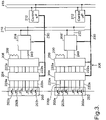
- Figures 2 and 3 show a schematic circuit diagram of the active battery balancing circuit if this invention.
- Balancing circuit 200 comprises a number of batteries 202 (each comprises a number of cells 202a-202n), arranged in series.
- the batteries are Li-ion batteries, but this circuitry will work with other battery types such as lead acid batteries, nickel-cadmium batteries or nickel-metal hydride batteries or others.
- FIG 2 there are four batteries 202 each connected to a battery balancing monitoring module 201. However, further batteries 202 may also be provided, and connected as described below.
- Each of the battery balancing modules 201 is connected to an AC balancing bus 210, which joins all of the battery balancing modules together.
- CAN communication bus 215 is also connected to each of the battery balancing modules 201 as well as to a battery control unit 250.
- the balancing bus 210 is also connected to the battery control unit 250, which is connected to cooling control means (not shown) via pathway 252, heating control means (not shown) via pathway 254 and to charging control means (not shown) via pathway 256.
- the battery control unit may also be connected to other control units (also not shown).
- Battery control unit 250 is also connected to a separate vehicle control unit 260, if the battery is intended to be for use in a vehicle.
- the control unit 250 is located remotely from the balancing circuit, but this may not be the case for all embodiments of the invention.
- a single bus may be provided which operates as a balancing bus 210 and also a communications bus 215.
- the separate balancing bus 210 and communication bus 215 will not be required.
- the use of only a single bus in this embodiment for both battery balancing and communication will reduce the wiring required for the system and will also reduce the overall cost of the system.
- FIG. 3 shows the battery balancing circuit 200 and battery balance monitoring module 201 in more detail.
- the battery balancing monitoring module 201 comprises monitoring means 204, switch matrix 206, resistor means 209 and voltage converter means 208, 208'.
- each unit 202 has six battery cells 202a-202n explicitly illustrated within the unit 202, but again, as indicated by the dashed line within the battery 202, more cells may be provided if required for each battery 202.
- Each cell 202a-202n is connected to the monitoring means 204, via a pathway 220a-220n.
- the monitoring means 204 is connected to switch matrix 206 via pathways 222a-222n (which align with pathways 220a-220n).
- a dump resistor 209 At one end of the switch matrix 206 is a dump resistor 209, this resistor is optional and is not required for all embodiments of the invention.
- the dump resistor 209 is only required when all of the cells 202a-202n are fully charged, and excess charge has to be dumped from the battery, rather than be balanced to a different cell of the battery.
- Each switch matrix 206 is connected to voltage convertor 208, and both voltage convertors are connected to balancing bus 210 via pathways 232.
- the voltage convertor 208 is a planar transformer, as this is a much more compact unit, and this will allow the overall circuitry to be greatly reduced in size.
- the voltage converter 208, 208' is a bi-directional DC-AC voltage converter that operates as a DC-AC converter in a first direction and as an AC-DC convertor in the opposite direction.
- connection 230 which connects the monitoring means 204 and the switch means 206 to the DC balancing bus 210 and also to control microprocessor 212, as well as CAN communication bus 215.
- the balancing bus 210 and communication bus 215 may be combined into a single bus for both functions thus reducing wiring required and lowering the cost.
- the monitoring means 204 monitors the charge in each of the cells 202a-202n, and once one of the cells 202a-202n of battery 202 reaches its maximum capacity (and therefore will prevent the remainder of the cells charging), the switch matrix 206 will operate to divert any excess charge from the fully charged cell 202a-202n, to the voltage convertor 208, to allow the remaining cells 202a-202n in the cell 202 to continue charging. This excess charge will be provided to the bi-directional DC-AC voltage convertor 208, 208' to be converted from DC to AC current (the voltage convertor 208, 208' operating in a first direction) which is then provided to the balancing bus 210.
- the excess AC charge that is diverted away from the original battery via voltage converter 208 can be shifted to a different battery 202 rather than simply being dissipated as heat for example.
- the excess charge is provided from the DC-AC convertor pathway of voltage convertor 208, 208' to balancing bus 210.
- This AC current can then be transferred from the balancing bus 210 back to a battery 202. This will happen by transferring the AC current to bi-directional voltage convertor 208, 208', where the AC-DC convertor pathway (in the opposite direction to the DC-AC conversion path) will convert the AC current from the balancing bus 210 back to DC which is then provided back to a cell 202a-202n of a battery 202 that requires additional charge.
- the excess charge is transferred to a different battery 202, or is transferred to a different cell 202a-202n within the battery 202 containing the original cell 202a-202n.
- Moving charge between cells 202a-202n rather than simply dissipating excess charge as heat ensures less energy is wasted overall as the battery 202 is charged. This will result in a lower charging time for the battery and eventually, to a reduced cost to the consumer.
- the microprocessor 212 is a field programmable gate array (FPGA).
- FPGA field programmable gate array
- the switching waveforms generated by the FPGA drive the voltage convertor 208, 208' and control the flow of charge through the voltage convertor 208, 208'.
- the use of an FPGA in the microprocessor 212 makes the control of the battery power more accurate.
- the microprocessor 212 may alternatively comprise a complex programmable logic device (CPLD) or an application specific integrated circuit (ASIC).
- CPLD complex programmable logic device
- ASIC application specific integrated circuit
- the cells 202a-202n are grouped together as shown (in batteries 202) and are provided with one voltage convertor 208, 208' per group.
- the switch matrix 206 is then used to select the specific battery 202 which requires balancing.
- the secondary side of the bi-directional voltage convertor 208 is connected to the AC balancing bus 210, and the primary side of the bi-directional voltage convertor is connected to battery 202 (via the switching matrix 206 and the monitoring means 204).
- the other voltage convertor 208' is connected the other way round. That is, the primary side is connected to the balancing bus 210, and the secondary side is connected to the battery 202.
- this arrangement may be reversed for each voltage converter.
- any number of cells 202a-202n may be providing charge to the balancing bus 210, which may be recovered to any other of the cells 202a-202n, except the cell that the charge originated from.
- the diverted charge has to be diverted by the voltage converters 208, 208' to the balancing bus 210 and cannot simply be diverted within a battery 202 to an alternate cell 202a-202n within the same battery 202.
- the active battery balancing circuit as described can be used to extend the useful life of a battery, and also during recycling of batteries that have exceeded their life span.
Landscapes
- Engineering & Computer Science (AREA)
- Power Engineering (AREA)
- Charge And Discharge Circuits For Batteries Or The Like (AREA)
Claims (8)
- Aktive Batterieausgleichsschaltung, die Folgendes umfasst:eine erste Batterieeinheit (202), die mehrere Zellen (202a...n) umfasst;mindestens eine weitere Batterieeinheit (202), die mehrere Zellen (202a...n) umfasst;getrennte bidirektionale DC/AC-Spannungswandler (208), die mit jeder Batterieeinheit (202) verbunden sind, um Gleichstrom in Wechselstrom in einer ersten Richtung und umgekehrt in der entgegengesetzten Richtung umzuwandeln;einen AC-Ausgleichsbus (210), der jeden Spannungswandler (208) verbindet;und einen Steuerungsmikroprozessor (212);wobei die Ausgleichsschaltung für Folgendes ausgebildet ist:a) Bereitstellen eines überschüssigen Gleichstromflusses von einer Batterieeinheit (202) zu einem der bidirektionalen Spannungswandler (208);b) Umwandeln des überschüssigen Gleichstroms in Wechselstrom, und Liefern dieses Wechselstroms an den AC-Ausgleichsbus (210);c) Liefern des überschüssigen Wechselstroms im AC-Ausgleichsbus (210) an einen der bidirektionalen Spannungswandler (208);d) Umwandeln des überschüssigen Wechselstroms unter Verwendung des bidirektionalen Spannungswandlers (208) in Gleichstrom, und Zurückführen des umgewandelten Gleichstroms zu einer Batterieeinheit 202, die eine zusätzliche Ladung benötigt, dadurch gekennzeichnet, dass der Spannungswandler (208) ein Planartransformator ist;wobei die Schaltung ferner eine Batteriebalance-Überwachungseinrichtung (204) umfasst, die zwischen den Batterieeinheiten (202) und den Spannungswandlern (208) angeschlossen ist und, wobei die Batteriebalance-Überwachungseinrichtung Folgendes umfasst:Überwachungseinrichtung (204), die mit jeder Batterieeinheit (202) verbunden ist,Schalteinrichtung (206), die zwischen der Überwachungseinrichtung (204) und dem Spannungswandler (208) angeschlossen ist.
- Aktive Batterieausgleichsschaltung gemäß Anspruch 1, wobei die Überwachungseinrichtung (204) ferner einen Widerstand (209) umfasst, der mit der Schalteinrichtung (206) verbunden ist.
- Aktive Batterieausgleichsschaltung gemäß einem der vorhergehenden Ansprüche, die ferner eine Steuereinrichtung (212) umfasst, die mit dem AC-Ausgleichsbus (210) verbunden ist.
- Aktive Batterieausgleichsschaltung gemäß einem der vorhergehenden Ansprüche, wobei die Batterieeinheiten (200) Li-Ionen-Batterieeinheiten sind.
- Aktive Batterieausgleichsschaltung gemäß einem der vorhergehenden Ansprüche, die einen Steuermikroprozessor (212) umfasst, der eines oder mehrere von einem feldprogrammierbaren Gate-Array (FPGA), einer komplexen programmierbaren Logikvorrichtung (CPLD) oder einer anwendungsspezifischen integrierten Schaltung (ASIC) umfasst.
- Aktive Batterieausgleichsschaltung gemäß einem der vorhergehenden Ansprüche, die ferner einen separaten Kommunikationsbus (215) umfasst.
- Aktive Batterieausgleichsschaltung gemäß einem der Ansprüche 1 bis 5, wobei der AC-Ausgleichsbus (210) so ausgebildet ist, dass er als Kommunikationsbus arbeitet.
- Verfahren zum Ausgleichen einer Batterie unter Verwendung einer aktiven Batterieausgleichsschaltung gemäß einem der vorhergehenden Ansprüche, das die folgenden Schritte umfasst:Versorgen einer ersten Batterieeinheit (202) mit Strom;Ableiten überschüssiger Ladung von der ersten Batterieeinheit (202) zu einem bidirektionalen DC/AC-Spannungswandler (208) und Umwandeln in Wechselstrom;Ableiten des umgewandelten Wechselstroms zu einem AC-Ausgleichsbus (210);Ableiten des Wechselstroms von dem AC-Ausgleichsbus (210) zu einem bidirektionalen AC/DC-Spannungswandler (208) zur Umwandlung in Gleichstrom;Ableiten des umgewandelten Gleichstroms zu einer der Batterieeinheiten (202).
Applications Claiming Priority (2)
| Application Number | Priority Date | Filing Date | Title |
|---|---|---|---|
| GBGB1511279.0A GB201511279D0 (en) | 2015-06-26 | 2015-06-26 | Battery |
| PCT/GB2016/051914 WO2016207663A1 (en) | 2015-06-26 | 2016-06-27 | Battery balancing circuit |
Publications (2)
| Publication Number | Publication Date |
|---|---|
| EP3314718A1 EP3314718A1 (de) | 2018-05-02 |
| EP3314718B1 true EP3314718B1 (de) | 2023-01-25 |
Family
ID=53872287
Family Applications (1)
| Application Number | Title | Priority Date | Filing Date |
|---|---|---|---|
| EP16732731.1A Active EP3314718B1 (de) | 2015-06-26 | 2016-06-27 | Batterieausgleichsschaltung |
Country Status (4)
| Country | Link |
|---|---|
| US (1) | US20180191173A1 (de) |
| EP (1) | EP3314718B1 (de) |
| GB (1) | GB201511279D0 (de) |
| WO (1) | WO2016207663A1 (de) |
Families Citing this family (8)
| Publication number | Priority date | Publication date | Assignee | Title |
|---|---|---|---|---|
| US20170033572A1 (en) * | 2015-07-27 | 2017-02-02 | Robert Bosch Gmbh | Capacity estimation in a secondary battery |
| CN109428357B (zh) * | 2017-08-31 | 2020-11-20 | 比亚迪股份有限公司 | 电池均衡方法、系统、车辆、存储介质及电子设备 |
| EP3657571A1 (de) * | 2018-11-26 | 2020-05-27 | Aptiv Technologies Limited | Batteriemodul |
| DE102019215338A1 (de) * | 2019-10-07 | 2021-04-08 | Robert Bosch Gmbh | Batterie und Verwendung einer solchen Batterie |
| EP3940914A4 (de) * | 2020-04-29 | 2022-09-07 | Huawei Digital Power Technologies Co., Ltd. | Energiespeichersystem |
| CN112331951B (zh) * | 2020-09-30 | 2021-12-03 | 傲普(上海)新能源有限公司 | 一种电池组被动均衡下的温度控制系统和方法 |
| CZ2020731A3 (cs) * | 2020-12-30 | 2022-07-13 | Česká energeticko-auditorská společnost, s. r. o. | Zapojení pro správu bateriového úložiště a způsob správy bateriového úložiště v tomto zapojení |
| US20220393492A1 (en) * | 2021-06-02 | 2022-12-08 | Power.Global, Pbc | Battery storage and allocation |
Family Cites Families (8)
| Publication number | Priority date | Publication date | Assignee | Title |
|---|---|---|---|---|
| US7449891B2 (en) * | 2003-10-14 | 2008-11-11 | General Motors Corporation | Managing service life of a battery |
| US20080284370A1 (en) * | 2005-03-11 | 2008-11-20 | Techtium, Ltd. | Portable Battery Operated Power Supply |
| US7889524B2 (en) * | 2007-10-19 | 2011-02-15 | Illinois Institute Of Technology | Integrated bi-directional converter for plug-in hybrid electric vehicles |
| US9331499B2 (en) * | 2010-08-18 | 2016-05-03 | Volterra Semiconductor LLC | System, method, module, and energy exchanger for optimizing output of series-connected photovoltaic and electrochemical devices |
| WO2013106906A1 (en) * | 2012-01-17 | 2013-07-25 | Ecamion Inc. | A control, protection and power management system for an energy storage system |
| EP2896110A4 (de) * | 2012-09-13 | 2015-09-16 | Socpra Sciences Et Genie Sec | Vorrichtung zur speicherung und abgabe von elektrischer energie mittels eines schwungrades und mehrerer elektrochemischer akkumulatoren |
| KR101470735B1 (ko) * | 2013-05-15 | 2014-12-08 | 주식회사 엘지씨엔에스 | 직렬 연결된 다수의 2차 전지 충방전을 위한 능동 벨런스회로와 알고리즘을 구비한 2차 전지 충방전 제어장치 및 방법 |
| RU2546978C2 (ru) * | 2013-06-27 | 2015-04-10 | Общество с ограниченной ответственностью "ЭнСол Технологии" | Аккумуляторная батарея и система управления аккумуляторной батареей |
-
2015
- 2015-06-26 GB GBGB1511279.0A patent/GB201511279D0/en not_active Ceased
-
2016
- 2016-06-27 US US15/739,112 patent/US20180191173A1/en not_active Abandoned
- 2016-06-27 WO PCT/GB2016/051914 patent/WO2016207663A1/en active Application Filing
- 2016-06-27 EP EP16732731.1A patent/EP3314718B1/de active Active
Also Published As
| Publication number | Publication date |
|---|---|
| EP3314718A1 (de) | 2018-05-02 |
| US20180191173A1 (en) | 2018-07-05 |
| WO2016207663A1 (en) | 2016-12-29 |
| GB201511279D0 (en) | 2015-08-12 |
Similar Documents
| Publication | Publication Date | Title |
|---|---|---|
| EP3314718B1 (de) | Batterieausgleichsschaltung | |
| KR101893045B1 (ko) | 배터리용 충전 밸런싱 시스템 | |
| US20150372279A1 (en) | Active battery stack system and method | |
| CN102422503B (zh) | 用于可充电电池组的电能管理电路 | |
| US8796992B2 (en) | Basic unit of lithium-ion battery, battery pack comprising the same, and charge/discharge equalizing method thereof | |
| US8907616B2 (en) | Hybrid power supply system | |
| US7282814B2 (en) | Battery controller and method for controlling a battery | |
| US8269455B2 (en) | Charge balancing system | |
| Lu et al. | Modularized buck-boost+ Cuk converter for high voltage series connected battery cells | |
| EP2372865A2 (de) | Stromversorgungsvorrichtung, die elektrische Eigenschafen von Battieren ausgleichen kann | |
| US20170054303A1 (en) | Battery system | |
| US20130038289A1 (en) | Battery-cell converter systems | |
| US10193356B2 (en) | Electrochemical energy accumulator and balancing method | |
| US10008861B2 (en) | Charge balancing in a battery | |
| US10862318B2 (en) | Bilevel equalizer for battery cell charge management | |
| Wei et al. | The research of vehicle power Li-ion battery pack balancing method | |
| Ketzer et al. | Evaluating circuit topologies for battery charge equalization | |
| Park et al. | Charge equalization with series coupling of multiple primary windings for hybrid electric vehicle li-ion battery system | |
| CN102832666A (zh) | 一种基于电感储能的串联电池组放电均衡电路 | |
| Hoque et al. | Voltage equalization for series connected lithium-ion battery cells | |
| Vitols | Efficiency of LiFePO4 battery and charger with a mixed two level balancing | |
| KR100815431B1 (ko) | 하이브리드 전기자동차 배터리 셀의 균등 에너지 백업장치 | |
| KR102552457B1 (ko) | 전력공급시스템 | |
| CN113708442A (zh) | 旁路型电池均衡装置及控制方法 | |
| EP4173886A1 (de) | Batteriesystem und verfahren zur steuerung des batteriesystems |
Legal Events
| Date | Code | Title | Description |
|---|---|---|---|
| STAA | Information on the status of an ep patent application or granted ep patent |
Free format text: STATUS: THE INTERNATIONAL PUBLICATION HAS BEEN MADE |
|
| PUAI | Public reference made under article 153(3) epc to a published international application that has entered the european phase |
Free format text: ORIGINAL CODE: 0009012 |
|
| STAA | Information on the status of an ep patent application or granted ep patent |
Free format text: STATUS: REQUEST FOR EXAMINATION WAS MADE |
|
| 17P | Request for examination filed |
Effective date: 20180124 |
|
| AK | Designated contracting states |
Kind code of ref document: A1 Designated state(s): AL AT BE BG CH CY CZ DE DK EE ES FI FR GB GR HR HU IE IS IT LI LT LU LV MC MK MT NL NO PL PT RO RS SE SI SK SM TR |
|
| AX | Request for extension of the european patent |
Extension state: BA ME |
|
| DAV | Request for validation of the european patent (deleted) | ||
| DAX | Request for extension of the european patent (deleted) | ||
| STAA | Information on the status of an ep patent application or granted ep patent |
Free format text: STATUS: EXAMINATION IS IN PROGRESS |
|
| 17Q | First examination report despatched |
Effective date: 20190718 |
|
| STAA | Information on the status of an ep patent application or granted ep patent |
Free format text: STATUS: THE APPLICATION IS DEEMED TO BE WITHDRAWN |
|
| 18D | Application deemed to be withdrawn |
Effective date: 20200129 |
|
| 18RA | Request filed for re-establishment of rights before grant |
Effective date: 20210211 |
|
| R18D | Application deemed to be withdrawn (corrected) |
Effective date: 20200129 |
|
| STAA | Information on the status of an ep patent application or granted ep patent |
Free format text: STATUS: EXAMINATION IS IN PROGRESS |
|
| 18RR | Decision to grant the request for re-establishment of rights before grant |
Free format text: ANGENOMMEN Effective date: 20210428 |
|
| STAA | Information on the status of an ep patent application or granted ep patent |
Free format text: STATUS: EXAMINATION IS IN PROGRESS |
|
| D18D | Application deemed to be withdrawn (deleted) | ||
| GRAP | Despatch of communication of intention to grant a patent |
Free format text: ORIGINAL CODE: EPIDOSNIGR1 |
|
| STAA | Information on the status of an ep patent application or granted ep patent |
Free format text: STATUS: GRANT OF PATENT IS INTENDED |
|
| INTG | Intention to grant announced |
Effective date: 20220315 |
|
| GRAS | Grant fee paid |
Free format text: ORIGINAL CODE: EPIDOSNIGR3 |
|
| GRAA | (expected) grant |
Free format text: ORIGINAL CODE: 0009210 |
|
| STAA | Information on the status of an ep patent application or granted ep patent |
Free format text: STATUS: THE PATENT HAS BEEN GRANTED |
|
| AK | Designated contracting states |
Kind code of ref document: B1 Designated state(s): AL AT BE BG CH CY CZ DE DK EE ES FI FR GB GR HR HU IE IS IT LI LT LU LV MC MK MT NL NO PL PT RO RS SE SI SK SM TR |
|
| REG | Reference to a national code |
Ref country code: CH Ref legal event code: EP |
|
| REG | Reference to a national code |
Ref country code: AT Ref legal event code: REF Ref document number: 1546485 Country of ref document: AT Kind code of ref document: T Effective date: 20230215 Ref country code: IE Ref legal event code: FG4D |
|
| REG | Reference to a national code |
Ref country code: DE Ref legal event code: R096 Ref document number: 602016077611 Country of ref document: DE |
|
| REG | Reference to a national code |
Ref country code: LT Ref legal event code: MG9D |
|
| REG | Reference to a national code |
Ref country code: NL Ref legal event code: MP Effective date: 20230125 |
|
| REG | Reference to a national code |
Ref country code: AT Ref legal event code: MK05 Ref document number: 1546485 Country of ref document: AT Kind code of ref document: T Effective date: 20230125 |
|
| PG25 | Lapsed in a contracting state [announced via postgrant information from national office to epo] |
Ref country code: NL Free format text: LAPSE BECAUSE OF FAILURE TO SUBMIT A TRANSLATION OF THE DESCRIPTION OR TO PAY THE FEE WITHIN THE PRESCRIBED TIME-LIMIT Effective date: 20230125 |
|
| PG25 | Lapsed in a contracting state [announced via postgrant information from national office to epo] |
Ref country code: RS Free format text: LAPSE BECAUSE OF FAILURE TO SUBMIT A TRANSLATION OF THE DESCRIPTION OR TO PAY THE FEE WITHIN THE PRESCRIBED TIME-LIMIT Effective date: 20230125 Ref country code: PT Free format text: LAPSE BECAUSE OF FAILURE TO SUBMIT A TRANSLATION OF THE DESCRIPTION OR TO PAY THE FEE WITHIN THE PRESCRIBED TIME-LIMIT Effective date: 20230525 Ref country code: NO Free format text: LAPSE BECAUSE OF FAILURE TO SUBMIT A TRANSLATION OF THE DESCRIPTION OR TO PAY THE FEE WITHIN THE PRESCRIBED TIME-LIMIT Effective date: 20230425 Ref country code: LV Free format text: LAPSE BECAUSE OF FAILURE TO SUBMIT A TRANSLATION OF THE DESCRIPTION OR TO PAY THE FEE WITHIN THE PRESCRIBED TIME-LIMIT Effective date: 20230125 Ref country code: LT Free format text: LAPSE BECAUSE OF FAILURE TO SUBMIT A TRANSLATION OF THE DESCRIPTION OR TO PAY THE FEE WITHIN THE PRESCRIBED TIME-LIMIT Effective date: 20230125 Ref country code: HR Free format text: LAPSE BECAUSE OF FAILURE TO SUBMIT A TRANSLATION OF THE DESCRIPTION OR TO PAY THE FEE WITHIN THE PRESCRIBED TIME-LIMIT Effective date: 20230125 Ref country code: ES Free format text: LAPSE BECAUSE OF FAILURE TO SUBMIT A TRANSLATION OF THE DESCRIPTION OR TO PAY THE FEE WITHIN THE PRESCRIBED TIME-LIMIT Effective date: 20230125 Ref country code: AT Free format text: LAPSE BECAUSE OF FAILURE TO SUBMIT A TRANSLATION OF THE DESCRIPTION OR TO PAY THE FEE WITHIN THE PRESCRIBED TIME-LIMIT Effective date: 20230125 |
|
| PG25 | Lapsed in a contracting state [announced via postgrant information from national office to epo] |
Ref country code: SE Free format text: LAPSE BECAUSE OF FAILURE TO SUBMIT A TRANSLATION OF THE DESCRIPTION OR TO PAY THE FEE WITHIN THE PRESCRIBED TIME-LIMIT Effective date: 20230125 Ref country code: PL Free format text: LAPSE BECAUSE OF FAILURE TO SUBMIT A TRANSLATION OF THE DESCRIPTION OR TO PAY THE FEE WITHIN THE PRESCRIBED TIME-LIMIT Effective date: 20230125 Ref country code: IS Free format text: LAPSE BECAUSE OF FAILURE TO SUBMIT A TRANSLATION OF THE DESCRIPTION OR TO PAY THE FEE WITHIN THE PRESCRIBED TIME-LIMIT Effective date: 20230525 Ref country code: GR Free format text: LAPSE BECAUSE OF FAILURE TO SUBMIT A TRANSLATION OF THE DESCRIPTION OR TO PAY THE FEE WITHIN THE PRESCRIBED TIME-LIMIT Effective date: 20230426 Ref country code: FI Free format text: LAPSE BECAUSE OF FAILURE TO SUBMIT A TRANSLATION OF THE DESCRIPTION OR TO PAY THE FEE WITHIN THE PRESCRIBED TIME-LIMIT Effective date: 20230125 |
|
| REG | Reference to a national code |
Ref country code: DE Ref legal event code: R097 Ref document number: 602016077611 Country of ref document: DE |
|
| PG25 | Lapsed in a contracting state [announced via postgrant information from national office to epo] |
Ref country code: SM Free format text: LAPSE BECAUSE OF FAILURE TO SUBMIT A TRANSLATION OF THE DESCRIPTION OR TO PAY THE FEE WITHIN THE PRESCRIBED TIME-LIMIT Effective date: 20230125 Ref country code: RO Free format text: LAPSE BECAUSE OF FAILURE TO SUBMIT A TRANSLATION OF THE DESCRIPTION OR TO PAY THE FEE WITHIN THE PRESCRIBED TIME-LIMIT Effective date: 20230125 Ref country code: EE Free format text: LAPSE BECAUSE OF FAILURE TO SUBMIT A TRANSLATION OF THE DESCRIPTION OR TO PAY THE FEE WITHIN THE PRESCRIBED TIME-LIMIT Effective date: 20230125 Ref country code: DK Free format text: LAPSE BECAUSE OF FAILURE TO SUBMIT A TRANSLATION OF THE DESCRIPTION OR TO PAY THE FEE WITHIN THE PRESCRIBED TIME-LIMIT Effective date: 20230125 Ref country code: CZ Free format text: LAPSE BECAUSE OF FAILURE TO SUBMIT A TRANSLATION OF THE DESCRIPTION OR TO PAY THE FEE WITHIN THE PRESCRIBED TIME-LIMIT Effective date: 20230125 |
|
| PGFP | Annual fee paid to national office [announced via postgrant information from national office to epo] |
Ref country code: GB Payment date: 20230718 Year of fee payment: 8 |
|
| PG25 | Lapsed in a contracting state [announced via postgrant information from national office to epo] |
Ref country code: SK Free format text: LAPSE BECAUSE OF FAILURE TO SUBMIT A TRANSLATION OF THE DESCRIPTION OR TO PAY THE FEE WITHIN THE PRESCRIBED TIME-LIMIT Effective date: 20230125 |
|
| PLBE | No opposition filed within time limit |
Free format text: ORIGINAL CODE: 0009261 |
|
| STAA | Information on the status of an ep patent application or granted ep patent |
Free format text: STATUS: NO OPPOSITION FILED WITHIN TIME LIMIT |
|
| 26N | No opposition filed |
Effective date: 20231026 |
|
| REG | Reference to a national code |
Ref country code: DE Ref legal event code: R119 Ref document number: 602016077611 Country of ref document: DE |
|
| PG25 | Lapsed in a contracting state [announced via postgrant information from national office to epo] |
Ref country code: MC Free format text: LAPSE BECAUSE OF FAILURE TO SUBMIT A TRANSLATION OF THE DESCRIPTION OR TO PAY THE FEE WITHIN THE PRESCRIBED TIME-LIMIT Effective date: 20230125 |
|
| PG25 | Lapsed in a contracting state [announced via postgrant information from national office to epo] |
Ref country code: SI Free format text: LAPSE BECAUSE OF FAILURE TO SUBMIT A TRANSLATION OF THE DESCRIPTION OR TO PAY THE FEE WITHIN THE PRESCRIBED TIME-LIMIT Effective date: 20230125 Ref country code: MC Free format text: LAPSE BECAUSE OF FAILURE TO SUBMIT A TRANSLATION OF THE DESCRIPTION OR TO PAY THE FEE WITHIN THE PRESCRIBED TIME-LIMIT Effective date: 20230125 |
|
| REG | Reference to a national code |
Ref country code: CH Ref legal event code: PL |
|
| REG | Reference to a national code |
Ref country code: BE Ref legal event code: MM Effective date: 20230630 |
|
| PG25 | Lapsed in a contracting state [announced via postgrant information from national office to epo] |
Ref country code: LU Free format text: LAPSE BECAUSE OF NON-PAYMENT OF DUE FEES Effective date: 20230627 |
|
| REG | Reference to a national code |
Ref country code: IE Ref legal event code: MM4A |
|
| PG25 | Lapsed in a contracting state [announced via postgrant information from national office to epo] |
Ref country code: LU Free format text: LAPSE BECAUSE OF NON-PAYMENT OF DUE FEES Effective date: 20230627 |
|
| PG25 | Lapsed in a contracting state [announced via postgrant information from national office to epo] |
Ref country code: IE Free format text: LAPSE BECAUSE OF NON-PAYMENT OF DUE FEES Effective date: 20230627 |
|
| PG25 | Lapsed in a contracting state [announced via postgrant information from national office to epo] |
Ref country code: IE Free format text: LAPSE BECAUSE OF NON-PAYMENT OF DUE FEES Effective date: 20230627 Ref country code: DE Free format text: LAPSE BECAUSE OF NON-PAYMENT OF DUE FEES Effective date: 20240103 Ref country code: CH Free format text: LAPSE BECAUSE OF NON-PAYMENT OF DUE FEES Effective date: 20230630 |