EP3314285B1 - Verfahren zur lokalisierung eines empfängers in einem positionierungssystem - Google Patents
Verfahren zur lokalisierung eines empfängers in einem positionierungssystem Download PDFInfo
- Publication number
- EP3314285B1 EP3314285B1 EP16730420.3A EP16730420A EP3314285B1 EP 3314285 B1 EP3314285 B1 EP 3314285B1 EP 16730420 A EP16730420 A EP 16730420A EP 3314285 B1 EP3314285 B1 EP 3314285B1
- Authority
- EP
- European Patent Office
- Prior art keywords
- receiver
- plk
- phase
- emitters
- initial position
- Prior art date
- Legal status (The legal status is an assumption and is not a legal conclusion. Google has not performed a legal analysis and makes no representation as to the accuracy of the status listed.)
- Active
Links
Images
Classifications
-
- G—PHYSICS
- G01—MEASURING; TESTING
- G01S—RADIO DIRECTION-FINDING; RADIO NAVIGATION; DETERMINING DISTANCE OR VELOCITY BY USE OF RADIO WAVES; LOCATING OR PRESENCE-DETECTING BY USE OF THE REFLECTION OR RERADIATION OF RADIO WAVES; ANALOGOUS ARRANGEMENTS USING OTHER WAVES
- G01S1/00—Beacons or beacon systems transmitting signals having a characteristic or characteristics capable of being detected by non-directional receivers and defining directions, positions, or position lines fixed relatively to the beacon transmitters; Receivers co-operating therewith
- G01S1/02—Beacons or beacon systems transmitting signals having a characteristic or characteristics capable of being detected by non-directional receivers and defining directions, positions, or position lines fixed relatively to the beacon transmitters; Receivers co-operating therewith using radio waves
- G01S1/08—Systems for determining direction or position line
- G01S1/20—Systems for determining direction or position line using a comparison of transit time of synchronised signals transmitted from non-directional antennas or antenna systems spaced apart, i.e. path-difference systems
-
- G—PHYSICS
- G01—MEASURING; TESTING
- G01S—RADIO DIRECTION-FINDING; RADIO NAVIGATION; DETERMINING DISTANCE OR VELOCITY BY USE OF RADIO WAVES; LOCATING OR PRESENCE-DETECTING BY USE OF THE REFLECTION OR RERADIATION OF RADIO WAVES; ANALOGOUS ARRANGEMENTS USING OTHER WAVES
- G01S19/00—Satellite radio beacon positioning systems; Determining position, velocity or attitude using signals transmitted by such systems
- G01S19/38—Determining a navigation solution using signals transmitted by a satellite radio beacon positioning system
- G01S19/39—Determining a navigation solution using signals transmitted by a satellite radio beacon positioning system the satellite radio beacon positioning system transmitting time-stamped messages, e.g. GPS [Global Positioning System], GLONASS [Global Orbiting Navigation Satellite System] or GALILEO
- G01S19/40—Correcting position, velocity or attitude
-
- G—PHYSICS
- G01—MEASURING; TESTING
- G01S—RADIO DIRECTION-FINDING; RADIO NAVIGATION; DETERMINING DISTANCE OR VELOCITY BY USE OF RADIO WAVES; LOCATING OR PRESENCE-DETECTING BY USE OF THE REFLECTION OR RERADIATION OF RADIO WAVES; ANALOGOUS ARRANGEMENTS USING OTHER WAVES
- G01S19/00—Satellite radio beacon positioning systems; Determining position, velocity or attitude using signals transmitted by such systems
- G01S19/01—Satellite radio beacon positioning systems transmitting time-stamped messages, e.g. GPS [Global Positioning System], GLONASS [Global Orbiting Navigation Satellite System] or GALILEO
- G01S19/03—Cooperating elements; Interaction or communication between different cooperating elements or between cooperating elements and receivers
- G01S19/10—Cooperating elements; Interaction or communication between different cooperating elements or between cooperating elements and receivers providing dedicated supplementary positioning signals
- G01S19/11—Cooperating elements; Interaction or communication between different cooperating elements or between cooperating elements and receivers providing dedicated supplementary positioning signals wherein the cooperating elements are pseudolites or satellite radio beacon positioning system signal repeaters
-
- G—PHYSICS
- G01—MEASURING; TESTING
- G01S—RADIO DIRECTION-FINDING; RADIO NAVIGATION; DETERMINING DISTANCE OR VELOCITY BY USE OF RADIO WAVES; LOCATING OR PRESENCE-DETECTING BY USE OF THE REFLECTION OR RERADIATION OF RADIO WAVES; ANALOGOUS ARRANGEMENTS USING OTHER WAVES
- G01S19/00—Satellite radio beacon positioning systems; Determining position, velocity or attitude using signals transmitted by such systems
- G01S19/38—Determining a navigation solution using signals transmitted by a satellite radio beacon positioning system
- G01S19/39—Determining a navigation solution using signals transmitted by a satellite radio beacon positioning system the satellite radio beacon positioning system transmitting time-stamped messages, e.g. GPS [Global Positioning System], GLONASS [Global Orbiting Navigation Satellite System] or GALILEO
- G01S19/42—Determining position
- G01S19/43—Determining position using carrier phase measurements, e.g. kinematic positioning; using long or short baseline interferometry
-
- G—PHYSICS
- G01—MEASURING; TESTING
- G01S—RADIO DIRECTION-FINDING; RADIO NAVIGATION; DETERMINING DISTANCE OR VELOCITY BY USE OF RADIO WAVES; LOCATING OR PRESENCE-DETECTING BY USE OF THE REFLECTION OR RERADIATION OF RADIO WAVES; ANALOGOUS ARRANGEMENTS USING OTHER WAVES
- G01S5/00—Position-fixing by co-ordinating two or more direction or position line determinations; Position-fixing by co-ordinating two or more distance determinations
- G01S5/02—Position-fixing by co-ordinating two or more direction or position line determinations; Position-fixing by co-ordinating two or more distance determinations using radio waves
- G01S5/10—Position of receiver fixed by co-ordinating a plurality of position lines defined by path-difference measurements, e.g. omega or decca systems
-
- G—PHYSICS
- G01—MEASURING; TESTING
- G01S—RADIO DIRECTION-FINDING; RADIO NAVIGATION; DETERMINING DISTANCE OR VELOCITY BY USE OF RADIO WAVES; LOCATING OR PRESENCE-DETECTING BY USE OF THE REFLECTION OR RERADIATION OF RADIO WAVES; ANALOGOUS ARRANGEMENTS USING OTHER WAVES
- G01S2205/00—Position-fixing by co-ordinating two or more direction or position line determinations; Position-fixing by co-ordinating two or more distance determinations
- G01S2205/01—Position-fixing by co-ordinating two or more direction or position line determinations; Position-fixing by co-ordinating two or more distance determinations specially adapted for specific applications
- G01S2205/02—Indoor
Definitions
- the present invention relates to a method for locating at least one receiver within a positioning system as well as such a positioning system.
- CDMA code division multiplexing
- GPS global positioning system
- GNSS global navigation satellite system
- the vast majority of known positioning systems are based on a triangulation or multilateration approach in order to define, in a global or local frame of reference, the coordinates of a mobile terminal, called a receiver.
- Sensor networks offer excellent performance but their infrastructure presents a very strong constraint.
- the sensors used are ultrasonic, infrared, pressure sensors or even electronic labels.
- the latter particularly of the "Near Field Communication” (NFC) type, are increasingly used, but do not allow continuous positioning, neither in time nor in space.
- NFC Near Field Communication
- Inertial systems are also used, implementing a reduced infrastructure but a complex mobile terminal and non-trivial modeling. These sensors are integrated into some current smart phones, " smartphones" in English.
- Image recognition systems are efficient but do not ensure total continuity: implementation constraints persist, these systems requiring conscious action by the user to take the picture, and requiring a non-blurred image, which limits the movement of the mobile terminal during shooting.
- Radar-type systems rely on measurements of the round-trip time of a wave, allowing a distance to be obtained, and on measurements of the direction of arrival in spherical coordinates. These systems represent a rather high simplification of the usual constraints of a positioning system, namely the synchronization between the parties involved and the necessary spatial diversity.
- a single transmitter is sufficient to determine a position.
- dedicated mobile terminals are required.
- Some approaches use dual antennas spaced one wavelength apart from the signal, and measure the phase difference of the signals received from the two antennas to define the angle of arrival of the transmitted signal.
- the patent US 4,646,096 describes a method using the principle of the movement of the constellation of satellites around a receiver by measuring and storing the phase variations of the carriers corresponding to the signals coming from said satellites, in order to determine the full ambiguity of the code measurements of the corresponding signals for single-channel receivers.
- the request WO 2014/060777 describes the positioning of a mobile terminal, using a signal sent by said terminal and received by multiple antennas of multiple wireless access points, and relying on calculations of phase differences between the different antennas to obtain an angle of arrival of the signal on the antennas.
- US 2007/0052583 discloses a system for determining the relative position of a mobile receiver with respect to its initial position, which receiver receives signals transmitted by a plurality of satellites. The position of the receiver with respect to its initial position is determined by incrementing the phases of the carriers of the signals transmitted by these satellites during the movement of the receiver.
- US 2002/0145563 describes a system for determining the motion of a human body, comprising transmitting antennas attached to the human body and receiving antennas installed in a space where the measurements will be taken.
- US 2009/0322603 discloses a positioning system comprising a receiving station which receives signals from transmitting stations and extracts carriers of these signals from pilot signals. These signals are then processed and received by mobile units to determine the positions of these units.
- Known repelite-based approaches leverage the receivers and transmitted GNSS signals to enable a single GNSS receiver, present in the mobile terminal, to provide a localization function.
- pseudo-satellites i.e. a network of terrestrial transmitters transmitting signals with the same structure as the signals sent by a satellite, as described in the article by Kee C. et al. "Centimeter-Accuracy Indoor Navigation Using GPS-Like Pseudolites", GPS World 2001, pages 14-20 .
- the most accurate measurements of GNSS signals which in particular allow centimetric positioning in good outdoor reception conditions, are used in these approaches, offering high-quality experimental performance, and being reliable and simple to use. In the short term, they will allow to reduce the number of transmitters required and to simplify system management, in particular by eliminating synchronization or by using low-cost transmitters.
- the signals developed within the framework of the European satellite positioning system project " Galileo" allow a significant reduction in interference levels, suggesting that it will be possible to preserve the bands used by GNSS signals to ensure full continuity of the location function.
- Geolocation using pseudolites calculates geometric intersections of spheres centered at known points, the positions of the pseudolites, using the propagation time of the signals to measure the radii of the spheres, as described in Chapter 2 of the book Kaplan E. and Hegarty C. "Understanding GPS Principles and Applications", Artech House, 2006, 2nd edition on.
- the propagation time of a signal can be measured using the code or the signal carrier.
- multipath in English, strongly affects the measurement times outdoors, and even more indoors, because of the presence of many obstacles, as described in chapter 6 of the aforementioned book and in the article by Fluerasu A. et al.
- Carrier phase measurements have the advantage of being less sensitive to the multiple path problem, and allow an accuracy of a few tens of centimeters, as presented in the articles of Rizos C. et al. "LocataNet: Intelligent Time-Synchronized Pseudolite Transceivers for cm-Level Stand-Alone Positioning", IAIN World Congress 2003 , and of I. Selmi et al. "Experimental Positioning Results of the Repealite Based Indoor Positioning System", IEEE International Conference on Indoor Positioning and Indoor Navigation 2012 .
- Kee et al. relies on a nonlinear version of the positioning algorithm described in Chapter 2 of the aforementioned book, leading to a non-guaranteed convergence of the algorithm in some situations.
- the methods described in the articles by Xiaoguang Wan et al. and Puengnim A. et al. rely on the use of extended Kalman filters, the first implementing measurements of the signal code and the Least square AMBiguity Adjustment (LAMBDA) approach with a static initial position, and the second using the motion of the receiver to linearize the problem.
- LAMBDA Least square AMBiguity Adjustment
- the invention aims to meet this need and achieves this, according to one of its aspects, by means of a method for locating at least one receiver within a positioning system according to claim 1.
- the method according to the invention does not require knowledge of the absolute value of the distance between the transmitter and the receiver during measurements. This provides absolute positioning, thanks to the movement of the receiver and from relative measurements of the phase variations of the carrier, providing results close to those of an integrated Doppler.
- the measurements of variation of distances between the transmitters and the receiver are possible, with a high precision, for example decimetric or centimetric, by measurements of the phase of the carrier of radio signals, in particular of the GNSS type. These measurements translate the relative radial displacement speed between the transmitters, which are fixed according to the invention, and the receiver.
- the localization method according to the invention has a lower sensitivity to disturbances due to the propagation of the signals.
- the invention requires only a reduced infrastructure, in particular a reduced number of transmitters, independent of each other, and not requiring synchronization with each other.
- the invention allows for continuity of positioning between the exterior and interior environments.
- the method according to the invention takes into account the fact that, depending on where one is moving, the distances between the transmitters and the receiver vary differently.
- the invention can be implemented with all current mobile terminal receivers, particularly mobile telephones.
- the method can be implemented indoors , for example for positioning objects in areas not covered by GPS or GNSS, such as buildings.
- the method according to the invention is advantageously based on the generation of GNSS type signals transmitted by radio, for example on RNSS frequencies, "Radio Navigation Satellite Services" in English, capable of being processed by GNSS receivers, at least with regard to their digital processing.
- the frequency of the signals emitted by the transmitters can be any, but is preferably equal to 1.575 GHz, the signals being for example of the GNSS Galileo type.
- transmitter can be substituted for the term " generator", and vice versa.
- a pseudolite PL1, PL2, PL3, PL4 is a transmitter synchronized to a global reference time system 31, common to the entire constellation.
- the pseudo-distance PR k (t) of a pseudolite PLk can be measured at a time t, or "pseudorange" in English, corresponding to an indirect distance measurement by identifying the time of reception of a signal coming from the pseudolite and dated at the time of transmission, when the clocks of the pseudolite and the receiver 30 are not synchronized.
- This measurement can be expressed by: x t ⁇ x plk 2 + y t ⁇ y plk 2 + z t ⁇ z plk 2 + c .
- b t PR k t , with (x(t), y(t), z(t)) the coordinates of the receiver at time t, (x plk , y plk , z plk ) the coordinates of the pseudolite PLk, assumed to be known, c the speed of light and b(t) the clock bias between the reference time of the constellation and the clock of the receiver at time t. It should be noted that the height z is considered to be known in the case of two-dimensional positioning.
- the pseudorange can be measured using the code delay or the carrier phase of the incoming signal.
- the expression becomes: x t ⁇ x plk 2 + y t ⁇ y plk 2 + z t ⁇ z plk 2 + c .
- b t ⁇ k t + ⁇ . N k , with ⁇ k the phase of the carrier depending on time t, ⁇ the wavelength and N k the ambiguity of the phase introduced previously, not depending on time.
- phase ambiguity does not depend on time, it is advantageous, to eliminate it, to measure the pseudo-distance of a transmitter according to the invention at two successive times t 1 and t 2 and to subtract the equations obtained: x t 2 ⁇ x plk 2 + y t 2 ⁇ y plk 2 + z t 2 ⁇ z plk 2 ⁇ x t 1 ⁇ x plk 2 + y t 1 ⁇ y plk 2 + z t 1 ⁇ z plk 2 + c .
- b t 2 ⁇ b t 1 ⁇ k t 2 ⁇ ⁇ k t 1
- At least a third instant t3 can be considered, corresponding to a receiver position x3 , y3 and a clock bias b( t3 ), to obtain a new measurement and increase the number of equations.
- the number of transmitters n pl is advantageously a function of the dimension m of the positioning and the number of measurements k pt carried out for different positions of the receiver: m . 1 + 1 k pt ⁇ n pl .
- the dimension m of the positioning can be equal to two or three, corresponding respectively to a two-dimensional or three-dimensional positioning.
- additional indications may facilitate the determination of the initial position of the receiver, for example an observation of the area of the environment in which the receiver is evolving and of its trajectory, making it possible to discriminate certain symmetries, and/or to determine whether or not the trajectory of the receiver intersects the straight line passing through the two transmitters.
- the method according to the invention can be adapted to the required and available conditions: a higher number of transmitters can be used if few phase measurements are to be performed, for example to quickly obtain the position of the receiver, or, on the contrary, a lower number of transmitters can be used if a reduced infrastructure is desired, a higher number of phase measurements then being performed.
- the length of the receiver's movement between two positions is also to be determined, depending on the geometry of the region covered by the positioning system.
- the variation of the carrier phase between a later position (x j , y j , z j ) and the predefined estimated initial position (x 1 , y 1 , z 1 ) of the receiver, corresponding to time t 1 and to the later time t j can be calculated by the relation: x I ⁇ x plk 2 + y I ⁇ y plk 2 + z ⁇ z plk 2 ⁇ x 1 ⁇ x plk 2 + y 1 ⁇ y plk 2 + z ⁇ z plk 2 + c .
- ⁇ b 1 I ⁇ k I ⁇ ⁇ k 1 .
- a first order Taylor series can be used to calculate the carrier phase variation: ⁇ has x k 1 dx 1 ⁇ has y k 1 dy 1 + has x k I dx I + has y k I dy I + c .
- the values dx 1 , dy 1 , dx j , dy j and d ⁇ b1 j are advantageously determined at each iteration of the algorithm.
- a product of matrices is advantageously used to calculate the distance variation ⁇ X:H.
- the method according to the invention is preferably repeated as long as the calculated distance variation is greater than a first predefined threshold.
- the choice of the estimated initial position of the receiver is fundamental for the convergence of the algorithm.
- the method according to the invention advantageously comprises a step in which, if the variation in distance is greater than a second predefined threshold, the predefined estimated initial position of the receiver is modified. The phase measurements can be repeated from this new estimated initial position.
- the initial position of the receiver thus determined belongs to the region covered by the positioning system, delimited by the positions of the transmitters.
- the estimated initial position of the receiver is advantageously retained as the actual position, otherwise, the method according to the invention can be repeated.
- the invention also relates, according to another of its aspects, to a positioning system according to claim 12.
- Each transmitter advantageously transmits on a different frequency. This eliminates the problem of glare or intrinsic interference between two signals transmitting on the same frequency.
- the invention also relates, according to another of its aspects, to a receiver according to claim 13 and intended to be used within a positioning system comprising at least two transmitters.
- the receiver advantageously comprises a phase-locked loop configured to measure the phase ⁇ k of the carrier of the signals emitted by the transmitters.
- the receiver is advantageously multichannel.
- a standard receiver for example, can be used as the receiver; no modification of such a receiver is necessary to implement the method according to the invention.
- the measurements are made for a single position of the receiver, which therefore does not need to be mobile in the environment.
- the method according to the invention does not require, during measurements, knowledge of the absolute value of the distance separating the generator from the receiver.
- the invention produces unambiguous instantaneous measurements making it possible to obtain absolute positioning.
- Measurements of geometric quantities representative of the position of the receiver relative to the generators are possible, with high precision, for example decimetric or centimetric, by measurements of phase difference of radio signals, in particular of the GNSS type.
- the two signals emitted by each generator are preferably emitted from two emission zones of the generator distant from each other by a predefined distance d 12 .
- the two signals emitted by each generator are advantageously emitted at the same frequency.
- the angle is advantageously taken in the plane defined by the two emission zones of the generator and the receiver. It is considered that the angle in the middle of the two emission zones is identical to the angles coming directly from each zone to the receiver, which is the case when the receiver is infinitely far from said emission zones. It is advantageous for the distance between the emission zones and the receiver to be greater than at least ten times the predefined distance between the zones, being for example greater than 2 meters.
- At least one second angle calculation is advantageously performed with at least one second generator, in order to perform a geometric intersection.
- This is equivalent to determining a hyperbola for a two-dimensional positioning, or a three-dimensional (3D) hyperboloid on which the receiver is located, with the emission zones of the generators being their foci.
- At least one second generator is advantageously used to obtain a system of equations and an intersection of the hyperbolas, to obtain the position (x r , y r ) of the receiver.
- At least two generators are required for two-dimensional positioning and three generators for three-dimensional positioning to perform the geometric intersections and obtain a single point.
- the position of the generators within the positioning system is assumed to be known.
- the generators are preferably static.
- the two signals emitted by each generator can come from at least two antennas belonging to the generator and separated from each other by a predefined distance.
- the predefined distance by which the two antennas of the same generator are distant from each other is advantageously equal to the wavelength of the carrier of the signals emitted by the antennas. This makes it possible to obtain unambiguous measurements at the receiver.
- the signals emitted by the same generator are preferably synchronized with each other, for example internally by the generator.
- Each generator advantageously transmits on a different frequency. This eliminates the problem of glare or intrinsic interference between two signals transmitting on the same frequency.
- the receiver is advantageously multichannel, at least a first channel being configured to detect the first signal from a generator, and at least a second channel being configured to detect the second signal from the same generator.
- a complete positioning system implementing these two methods makes it possible, from the same phase measurements, to have at least three operating modes: absolute positioning by performing differences, at a given time, between the two antennas of a generator and this for several generators, then relative positioning from the position obtained, with decimetric precision, by phase difference measurements at successive times, then absolute positioning in motion by analyzing the evolution of the phase of the carriers coming from the various antennas at several successive times.
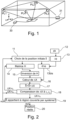
- the system 1 comprises a receiver 2 mobile within the system 1 and a plurality of transmitters PL1, PL2, PL3, PL4 forming a local constellation.
- system 1 can be implemented indoors , for example inside a building, or outdoors in a very urban area, between very high walls for example.
- Each transmitter PL1, PL2, PL3, PL4 preferably transmits a signal comprising a carrier modulated by a code.
- the signals emitted by transmitters PL1, PL2, PL3, PL4 are for example GNSS signals with a frequency equal to 1.575 GHz.
- the receiver 2 is configured to detect the signals emitted by the transmitters.
- the latter are for example received by the antenna of the receiver 2 then amplified and converted into an intermediate frequency IF lower than their initial frequency.
- reception channels of the receiver 2 These signals are in the example considered sampled, then digitized before being processed by the reception channels of the receiver 2. These reception channels can implement tracking loops.
- the receiver 2 advantageously comprises a phase-locked loop configured to measure the phase c of the carrier of the signals emitted by the transmitters.
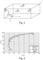
- a predefined estimated initial position X ⁇ is chosen for the receiver 2.
- the receiver 2 performs successive measurements of the phase ⁇ k of the carrier of the signal emitted by each transmitter PL1, PL2, PL3, PL4, for different subsequent positions of the receiver (x j , y j , z j ).
- a step 13 the variations ⁇ of the phase of the carrier of the signals between each subsequent position of the receiver 2 for which the phase ⁇ k was measured and the estimated initial position of the receiver are calculated, for each transmitter PL1, PL2, PL3, PL4.
- the matrix d ⁇ defined previously is created in a step 13bis.
- the matrix H defined previously is created in a step 14 and is inverted in a step 15.
- the distance variation ⁇ X is calculated in a step 16.
- the distance variation ⁇ X thus calculated and the predefined estimated initial position X ⁇ of the receiver 2 are added during a step 17 in order to form a new initial position X ⁇ .
- the distance variation ⁇ X is compared to a second predefined threshold ⁇ 2 . If ⁇ X is greater than this second predefined threshold, the predefined estimated initial position X ⁇ of the receiver 2 is modified, the phase and phase variation measurements ⁇ being repeated from this new estimated initial position.
- ⁇ X is less than this second predefined threshold ⁇ 2 , it is compared to a first predefined threshold ⁇ 1 , the method according to the invention being advantageously repeated, from step 14, as long as the variation in distance ⁇ X is greater than this first predefined threshold.
- the distance variation ⁇ X is less than the first predefined threshold ⁇ 1 , it is checked, during a step 19, whether the initial position of the receiver thus determined belongs to the region covered by the positioning system 1, delimited by the positions of the transmitters.
- the estimated initial position X ⁇ of the receiver 2 is retained as the real position during a step 20, otherwise, the method is repeated.
- the first predefined threshold is between 10 -5 m and 10 -1 m, for example being equal to 10 -2 m.
- the second predefined threshold is between 10 2 m and 10 5 m, for example being equal to 10 3 m.
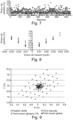
- FIG. 4 represents results obtained by implementing the invention in a 20 m by 30 m U-shaped urban canyon formed by tall buildings.
- four transmitters are deployed on the top floor of the buildings, at an altitude of approximately 18 m.
- a receiver 2 is moving in this environment.
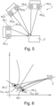
- the receiver 2 has an estimated initial position P0, then makes a round trip between the positions P0 and P3 passing through the subsequent positions P1 and P2, then goes from the position P0 to the position P4.
- the method for locating the receiver 2 according to the invention is implemented and the positions obtained are compared with the actual trajectory, as visible in the figure 4
- the reconstructed trajectory obtained is very close to the real trajectory, known beforehand for the needs of the experiment, the deviation remaining below 50 cm, as shown in the table below showing the error and the average error for each position.
- Positions P3 and P4 give the largest errors, because they are more difficult to estimate due to the configuration of the trajectory, corresponding to a multiple path and cycle slips cumulating sources of error.
- the method according to the invention was thus used to correct position P4, using a measurement additional at an intermediate position between P3 and P4, leading to the result P4c in the table above, giving a lower error.
- the last column of the table shows the results obtained for the extended horizontal dilution of precision, a value specifying the influence of the geometry of the environment on the precision of the positioning system, and adapted to the method according to the invention, thus representing the influence of the measurement error on the initial position of the receiver.
- the number of transmitters n pl of system 1 is a function of the dimension m of the positioning and of the number of measurements k pt carried out for different positions of receiver 2: m . 1 + 1 k pt ⁇ n pl .
- System 1 comprises a receiver 2 and three generators PL1, PL2, PL3 forming a local constellation.
- Each generator PL1, PL2, PL3 emits, in the example described, on the same carrier, two signals each having a different code.
- the transmitters can be the generators described previously. These two signals are emitted from two emission zones PL1 1 , PLh of the generator PL1 distant from each other by a predefined distance d 12 .
- the two signals emitted by each generator PL1, PL2, PL3 come from two antennas belonging to the generator and distant from each other by a predefined distance equal for example to the wavelength of the carrier of the signals emitted by the antennas.
- the signals emitted by the same generator are preferably synchronized with each other.
- Each generator PL1, PL2, PL3 preferably emits on a different frequency.
- the signals emitted by the generators PL1, PL2, PL3 are for example GNSS signals with a frequency equal to 1.575 GHz.
- the receiver 2 is configured to detect the signals emitted by the generators.
- the receiver 2 is advantageously configured to measure, for each of the generators PL1, PL2, PL3, the phase difference ⁇ j between the two signals emitted by the generator PLj.
- the receiver 2 is advantageously configured to calculate at least one geometric quantity representative of the position of the receiver relative to the generators PL1, PL2, PL3, in order to obtain its position (x r , y r ) within the system 1.
- FIGS. 7 to 9 represent results obtained by implementing the invention in a hall of 20 m by 20 m, in which two generators PL1 and PL2 are positioned at positions (0, 0) and (20, 0), thus being positioned on the same side of the hall.
- the method according to the invention is implemented, as defined above, to find a receiver 2, located at the coordinates (5; 15) of the hall. Approximately 660 phase difference measurements are carried out in order to evaluate the performance of the method according to the invention.
- FIG 9 shows the positions of receiver 2 calculated according to the invention in the Oxy plane, the point sought being represented by a square at coordinates (5, 15) and the various points calculated being represented by dark diamonds. Rolling averages over 10 points were carried out, represented by triangles, confirming that the positioning accuracy is of the order of thirty centimeters.
- the light diamond represents the general average of the point obtained over the 650 measurements, which happens to be 7.5 cm from the actual position of receiver 2.
- GPS and GNSS signals can be used, for example Wifi, 4G, GSM or radio signals.
- the methods according to the invention can be coupled with other geolocation methods, such as methods using a mobile reader, beacons and a geolocation and guidance application executable on said reader.
- the invention can be implemented in places where team sports are practiced, in particular indoors, for example by fixing or incorporating a system in football or handball goals in order to calculate the position of the players in real time, or on construction sites, for example for the installation of false ceilings, using one or more strips made up of a network of around ten antennas, or in large shopping centers.
- the invention can be used outdoors, making it possible to do without a base station.
Landscapes
- Engineering & Computer Science (AREA)
- Radar, Positioning & Navigation (AREA)
- Remote Sensing (AREA)
- Physics & Mathematics (AREA)
- General Physics & Mathematics (AREA)
- Computer Networks & Wireless Communication (AREA)
- Position Fixing By Use Of Radio Waves (AREA)
- Signal Processing (AREA)
Claims (14)
- Verfahren zur Lokalisierung mindestens eines Empfängers (2) innerhalb eines Positionierungssystems (1), wobei das System umfasst:- mindestens zwei Sender (PL1, PL2) für eine Positionierung in zwei Dimensionen und mindestens drei Sender (PL1, PL2, PL3) für eine Positionierung in drei Dimensionen, wobei jeder Sender ein Signal sendet, das einen mit einem Code modulierten Träger umfasst, wobei die Position der Sender innerhalb des Positionierungssystems als bekannt vorausgesetzt wird, und- einen innerhalb des Systems (1) beweglichen Empfänger (2), der dafür ausgelegt ist, die von den Sendern (PL1, PL2) gesendeten Signale zu detektieren, wobei das Verfahren dadurch gekennzeichnet ist, dass:- während der Bewegung des Empfängers (2), ausgehend von einer vordefinierten geschätzten Anfangsposition x1, y1, z1 dieses Letzteren, aufeinander folgende Messungen der Phase Φk des Trägers des von jedem Sender (PLk) gesendeten Signals für verschiedene spätere Positionen xj, yj, zj des Empfängers (2) ausgeführt werden,- die Änderungen der Phase dΔΦ des Trägers der Signale zwischen jeder späteren Position xj, yj, zj des Empfängers (2), für welche die Phase Φk gemessen worden ist, und der geschätzten Anfangsposition x1, y1, z1 des Empfängers (2) berechnet werden, für jeden Sender (PLk), und- diese Phasenänderungen dΔΦ verwendet werden, um eine Entfernungsänderung ΔX ausgehend von der vordefinierten geschätzten Anfangsposition x1, y1, z1 des Empfängers (2) zu berechnen, wobei die tatsächliche Anfangsposition dieses Letzteren innerhalb des Positionierungssystems (1) auf der Basis mindestens dieser Entfernungsänderung und der bekannten Position der mindestens zwei Sender bestimmt wird.
- Verfahren nach Anspruch 1, wobei die Änderung der Phase


- Verfahren nach einem der vorhergehenden Ansprüche, wobei eine Taylorreihe erster Ordnung verwendet wird, um die Änderung der Phase des Trägers zu berechnen:


- Verfahren nach Anspruch 3, wobei ein Matrixprodukt verwendet wird, um die Entfernungsänderung ΔX zu berechnen: H.ΔX = dΔφ, mit


- Verfahren nach einem der vorhergehenden Ansprüche, welches reiteriert wird, solange die Entfernungsänderung ΔX größer als ein erster vordefinierter Schwellenwert (ε1) ist.
- Verfahren nach einem der vorhergehenden Ansprüche, welches außerdem einen Schritt umfasst, in dem, falls die Entfernungsänderung ΔX größer als ein zweiter vordefinierter Schwellenwert (ε2) ist, die vordefinierte geschätzte Anfangsposition des Empfängers (2) geändert wird, wobei die Phasenmessungen insbesondere ausgehend von dieser neuen geschätzten Anfangsposition reiteriert werden.
- Verfahren nach Anspruch 5, wobei, wenn die Entfernungsänderung ΔX kleiner als der erste vordefinierte Schwellenwert (ε1) ist, überprüft wird, ob die so bestimmte Anfangsposition des Empfängers (2) dem von dem Positionierungssystem (1) abgedeckten Bereich angehört, der durch die Positionen der Sender (PLk) begrenzt wird.
- Verfahren nach dem vorhergehenden Anspruch, wobei, falls die bestimmte Anfangsposition des Empfängers (2) dem von dem Positionierungssystem (1) abgedeckten Bereich angehört, die geschätzte Anfangsposition des Empfängers (2) als tatsächliche Position beibehalten wird und andernfalls das Verfahren reiteriert wird.
- Verfahren nach einem der vorhergehenden Ansprüche, wobei die Anzahl der Sender npl von der Dimension m der Positionierung und von der Anzahl der Messungen kpt, die für verschiedene Positionen des Empfängers (2) ausgeführt werden, abhängig ist:

- Verfahren nach einem der vorhergehenden Ansprüche, wobei die Frequenz der von den Sendern (PLk) gesendeten Signale gleich 1,575 GHz ist, wobei die Signale insbesondere vom Typ GNSS Galileo sind.
- Verfahren nach einem der vorhergehenden Ansprüche, welches im Innenbereich durchgeführt wird.
- Empfänger (2), der dazu bestimmt ist, innerhalb eines Positionierungssystems (1) verwendet zu werden, das mindestens zwei Sender (PL1, PL2) für eine Positionierung in zwei Dimensionen und mindestens drei Sender (PL1, PL2, PL3) für eine Positionierung in drei Dimensionen umfasst, wobei jeder Sender ein Signal sendet, das einen mit einem Code modulierten Träger umfasst, wobei die Position der Sender innerhalb des Positionierungssystems als bekannt vorausgesetzt wird, wobei der Empfänger (2) innerhalb des Systems (1) beweglich ist und dafür ausgelegt ist, die von den Sendern (PL1, PL2) gesendeten Signale zu detektieren,
wobei der Empfänger (2) dadurch gekennzeichnet ist, dass er dafür ausgelegt ist:- während seiner Bewegung innerhalb des Systems (1), ausgehend von einer vordefinierten geschätzten Anfangsposition x1, y1, z1, aufeinander folgende Messungen der Phase Φk des Trägers des von jedem Sender (PLk) gesendeten Signals für verschiedene spätere Positionen xj, yj, zj des Empfängers (2) auszuführen,- die Änderungen der Phase dΔΦ des Trägers der Signale zwischen jeder späteren Position xj, yj, zj des Empfängers (2), für welche die Phase Φk gemessen worden ist, und der geschätzten Anfangsposition x1, y1, z1 des Empfängers (2) zu berechnen, für jeden Sender (PLk), und- diese Phasenänderungen dΔΦ zu verwenden, um eine Entfernungsänderung ΔX ausgehend von der vordefinierten geschätzten Anfangsposition x1, y1, z1 des Empfängers (2) zu berechnen, wobei die tatsächliche Anfangsposition dieses Letzteren innerhalb des Positionierungssystems (1) auf der Basis mindestens dieser Entfernungsänderung und der bekannten Position der mindestens zwei Sender bestimmt wird. - Empfänger nach dem vorhergehenden Anspruch, welcher ein Phasenregelschleife aufweist, die dafür ausgelegt ist, die Phase Φk des Trägers der von den Sendern (PL1, PL2) gesendeten Signale zu messen.
- Positionierungssystem (1), welches aufweist:- mindestens zwei Sender (PL1, PL2), wobei jeder Sender ein Signal sendet, das einen mit einem Code modulierten Träger umfasst, und- einen Empfänger (2) nach Anspruch 12.
Applications Claiming Priority (2)
| Application Number | Priority Date | Filing Date | Title |
|---|---|---|---|
| FR1555805A FR3038067B1 (fr) | 2015-06-24 | 2015-06-24 | Procede de localisation d'un recepteur au sein d'un systeme de positionnement |
| PCT/EP2016/064321 WO2016207168A1 (fr) | 2015-06-24 | 2016-06-21 | Procede de localisation d'un recepteur au sein d'un systeme de positionnement |
Publications (2)
| Publication Number | Publication Date |
|---|---|
| EP3314285A1 EP3314285A1 (de) | 2018-05-02 |
| EP3314285B1 true EP3314285B1 (de) | 2024-08-14 |
Family
ID=54545217
Family Applications (1)
| Application Number | Title | Priority Date | Filing Date |
|---|---|---|---|
| EP16730420.3A Active EP3314285B1 (de) | 2015-06-24 | 2016-06-21 | Verfahren zur lokalisierung eines empfängers in einem positionierungssystem |
Country Status (4)
| Country | Link |
|---|---|
| US (1) | US20180341025A1 (de) |
| EP (1) | EP3314285B1 (de) |
| FR (1) | FR3038067B1 (de) |
| WO (1) | WO2016207168A1 (de) |
Families Citing this family (6)
| Publication number | Priority date | Publication date | Assignee | Title |
|---|---|---|---|---|
| BE1027136B1 (nl) * | 2019-03-21 | 2020-10-19 | Rombit Nv | Methode, systeem en computerprogrammaproduct voor het bepalen van een positie ten opzichte van een begrensde ruimte |
| US11729592B2 (en) * | 2020-03-26 | 2023-08-15 | Universal Lighting Technologies Inc. | Angle of arrival commissioning of lighting devices |
| FR3125597B1 (fr) * | 2021-07-23 | 2023-09-22 | Paris Sciences Et Lettres | Dispositif et procédé de positionnement centimetrique d’un mobile |
| CN115407379A (zh) * | 2022-08-29 | 2022-11-29 | 东南大学 | 一种基于伪卫星和uwb融合定位系统的模糊度解算方法 |
| CN117784816B (zh) * | 2023-12-26 | 2024-10-29 | 深圳市达辰威科技集团有限公司 | 基于uwb的无人机野外搜救方法及装置 |
| CN119851375A (zh) * | 2025-01-03 | 2025-04-18 | 国网湖北省电力有限公司十堰供电公司 | 一种基于五防系统的全域安全管理方法及管理系统 |
Family Cites Families (11)
| Publication number | Priority date | Publication date | Assignee | Title |
|---|---|---|---|---|
| US4646096A (en) | 1984-10-05 | 1987-02-24 | Litton Systems, Inc. | Enhanced global positioning system Delta-Range processing |
| US5477458A (en) | 1994-01-03 | 1995-12-19 | Trimble Navigation Limited | Network for carrier phase differential GPS corrections |
| US5999123A (en) * | 1995-09-13 | 1999-12-07 | Rockwell International Corporation | Time-relative positioning for static applications |
| US6549165B2 (en) | 2001-01-19 | 2003-04-15 | Agence Spatiale Europeenne | Ocean altimetry interferometric method and device using GNSS signals |
| US6784826B2 (en) * | 2001-01-26 | 2004-08-31 | Tera Research Incorporated | Body motion tracking system |
| US7212155B2 (en) * | 2004-05-07 | 2007-05-01 | Navcom Technology, Inc. | GPS navigation using successive differences of carrier-phase measurements |
| US7522099B2 (en) * | 2005-09-08 | 2009-04-21 | Topcon Gps, Llc | Position determination using carrier phase measurements of satellite signals |
| WO2012151006A1 (en) * | 2011-03-22 | 2012-11-08 | Trimble Navigation Limited | Gnss signal processing with delta phase |
| US7671794B2 (en) | 2008-06-02 | 2010-03-02 | Enpoint, Llc | Attitude estimation using intentional translation of a global navigation satellite system (GNSS) antenna |
| US7990314B2 (en) * | 2008-06-30 | 2011-08-02 | Liao Henry H | Method and system for locating a geographical position using broadcast frequency modulation signals |
| WO2014060777A2 (en) | 2012-10-19 | 2014-04-24 | Ucl Business Plc | Apparatus and method for determining the location of a mobile device using multiple wireless access points |
-
2015
- 2015-06-24 FR FR1555805A patent/FR3038067B1/fr active Active
-
2016
- 2016-06-21 US US15/735,675 patent/US20180341025A1/en not_active Abandoned
- 2016-06-21 WO PCT/EP2016/064321 patent/WO2016207168A1/fr not_active Ceased
- 2016-06-21 EP EP16730420.3A patent/EP3314285B1/de active Active
Non-Patent Citations (1)
| Title |
|---|
| ALEXANDRE VERVISCH-PICOIS ET AL: "Delta Carrier Range algorithm for indoor positioning application to pseudolite-like transmitters", 2016 INTERNATIONAL CONFERENCE ON INDOOR POSITIONING AND INDOOR NAVIGATION (IPIN), IEEE, 4 October 2016 (2016-10-04), pages 1 - 8, XP033005662, DOI: 10.1109/IPIN.2016.7743669 * |
Also Published As
| Publication number | Publication date |
|---|---|
| FR3038067B1 (fr) | 2017-08-18 |
| US20180341025A1 (en) | 2018-11-29 |
| WO2016207168A1 (fr) | 2016-12-29 |
| EP3314285A1 (de) | 2018-05-02 |
| FR3038067A1 (fr) | 2016-12-30 |
Similar Documents
| Publication | Publication Date | Title |
|---|---|---|
| Wang et al. | Multi-frequency smartphone positioning performance evaluation: insights into A-GNSS PPP-B2b services and beyond | |
| Xie et al. | Measuring GNSS multipath distributions in urban canyon environments | |
| Kos et al. | Effects of multipath reception on GPS positioning performance | |
| Darugna et al. | RTK and PPP-RTK using smartphones: From short-baseline to long-baseline applications | |
| US11656315B2 (en) | System and method for ultrawideband position location | |
| WO2016207168A1 (fr) | Procede de localisation d'un recepteur au sein d'un systeme de positionnement | |
| KR102096677B1 (ko) | 광역 위치결정 시스템(waps)에서의 신호 송신 방법, 저장매체 및 네트워크. | |
| TWI438465B (zh) | 運用廣播調頻訊號定位地理位置之方法、系統及移動單元 | |
| US10502840B2 (en) | Outlier detection for satellite positioning system using visual inertial odometry | |
| WO2014171999A2 (en) | Method and system for high-accuracy differential tracking of global positioning system (gps) receivers | |
| JP7499773B2 (ja) | 測距装置、測距方法 | |
| CN103257337A (zh) | 一种灾后搜救集群定位方法 | |
| Hobiger et al. | GLONASS-R: GNSS reflectometry with a frequency division multiple access-based satellite navigation system | |
| US9766338B2 (en) | GNSS cooperative receiver system | |
| RU2013105445A (ru) | Способ оценки направления поступления навигационных сигналов в приемник после отражения от стен в спутниковой системе позиционирования | |
| WO2015142985A1 (en) | Gnss satellite signal spoofer direction determination | |
| KR100899545B1 (ko) | 항법 위성 전체 관측법을 이용한 시각 전송방법 | |
| US9523763B2 (en) | Satellite-based integer cycle ambiguity resolution of local medium wave radio signals | |
| EP3314291B1 (de) | Verfahren zur ortung eines empfängers in einem positionierungssystem | |
| Gan et al. | An approach to improve the indoor positioning performance of pseudolite/UWB system with ambiguity resolution | |
| US20250004142A1 (en) | Global navigation satellite systems (gnss) localization with residual grid representation | |
| US20240230823A9 (en) | Method, apparatus and system for performing position location using cellular signals | |
| KR101705882B1 (ko) | 기준국 환경에서 수신기의 위치 정보를 이용한 사이클 슬립 검출 장치 및 방법 | |
| Al Aziz | Navigation for UAVs using signals of opportunity | |
| FR3003961A1 (fr) | Procede de formation de faisceau signaux d'un recepteur de signaux d'un systeme de navigation par satellites pour ameliorer la resistance au brouillage. |
Legal Events
| Date | Code | Title | Description |
|---|---|---|---|
| STAA | Information on the status of an ep patent application or granted ep patent |
Free format text: STATUS: THE INTERNATIONAL PUBLICATION HAS BEEN MADE |
|
| PUAI | Public reference made under article 153(3) epc to a published international application that has entered the european phase |
Free format text: ORIGINAL CODE: 0009012 |
|
| STAA | Information on the status of an ep patent application or granted ep patent |
Free format text: STATUS: REQUEST FOR EXAMINATION WAS MADE |
|
| 17P | Request for examination filed |
Effective date: 20180124 |
|
| AK | Designated contracting states |
Kind code of ref document: A1 Designated state(s): AL AT BE BG CH CY CZ DE DK EE ES FI FR GB GR HR HU IE IS IT LI LT LU LV MC MK MT NL NO PL PT RO RS SE SI SK SM TR |
|
| AX | Request for extension of the european patent |
Extension state: BA ME |
|
| DAV | Request for validation of the european patent (deleted) | ||
| DAX | Request for extension of the european patent (deleted) | ||
| STAA | Information on the status of an ep patent application or granted ep patent |
Free format text: STATUS: EXAMINATION IS IN PROGRESS |
|
| 17Q | First examination report despatched |
Effective date: 20200304 |
|
| GRAP | Despatch of communication of intention to grant a patent |
Free format text: ORIGINAL CODE: EPIDOSNIGR1 |
|
| STAA | Information on the status of an ep patent application or granted ep patent |
Free format text: STATUS: GRANT OF PATENT IS INTENDED |
|
| INTG | Intention to grant announced |
Effective date: 20240313 |
|
| P01 | Opt-out of the competence of the unified patent court (upc) registered |
Effective date: 20240528 |
|
| GRAS | Grant fee paid |
Free format text: ORIGINAL CODE: EPIDOSNIGR3 |
|
| GRAA | (expected) grant |
Free format text: ORIGINAL CODE: 0009210 |
|
| STAA | Information on the status of an ep patent application or granted ep patent |
Free format text: STATUS: THE PATENT HAS BEEN GRANTED |
|
| AK | Designated contracting states |
Kind code of ref document: B1 Designated state(s): AL AT BE BG CH CY CZ DE DK EE ES FI FR GB GR HR HU IE IS IT LI LT LU LV MC MK MT NL NO PL PT RO RS SE SI SK SM TR |
|
| REG | Reference to a national code |
Ref country code: GB Ref legal event code: FG4D Free format text: NOT ENGLISH |
|
| REG | Reference to a national code |
Ref country code: CH Ref legal event code: EP |
|
| REG | Reference to a national code |
Ref country code: DE Ref legal event code: R096 Ref document number: 602016088875 Country of ref document: DE |
|
| REG | Reference to a national code |
Ref country code: IE Ref legal event code: FG4D Free format text: LANGUAGE OF EP DOCUMENT: FRENCH |
|
| REG | Reference to a national code |
Ref country code: LT Ref legal event code: MG9D |
|
| REG | Reference to a national code |
Ref country code: NL Ref legal event code: MP Effective date: 20240814 |
|
| PG25 | Lapsed in a contracting state [announced via postgrant information from national office to epo] |
Ref country code: NO Free format text: LAPSE BECAUSE OF FAILURE TO SUBMIT A TRANSLATION OF THE DESCRIPTION OR TO PAY THE FEE WITHIN THE PRESCRIBED TIME-LIMIT Effective date: 20241114 |
|
| REG | Reference to a national code |
Ref country code: AT Ref legal event code: MK05 Ref document number: 1713781 Country of ref document: AT Kind code of ref document: T Effective date: 20240814 |
|
| PG25 | Lapsed in a contracting state [announced via postgrant information from national office to epo] |
Ref country code: GR Free format text: LAPSE BECAUSE OF FAILURE TO SUBMIT A TRANSLATION OF THE DESCRIPTION OR TO PAY THE FEE WITHIN THE PRESCRIBED TIME-LIMIT Effective date: 20241115 Ref country code: PL Free format text: LAPSE BECAUSE OF FAILURE TO SUBMIT A TRANSLATION OF THE DESCRIPTION OR TO PAY THE FEE WITHIN THE PRESCRIBED TIME-LIMIT Effective date: 20240814 Ref country code: FI Free format text: LAPSE BECAUSE OF FAILURE TO SUBMIT A TRANSLATION OF THE DESCRIPTION OR TO PAY THE FEE WITHIN THE PRESCRIBED TIME-LIMIT Effective date: 20240814 Ref country code: PT Free format text: LAPSE BECAUSE OF FAILURE TO SUBMIT A TRANSLATION OF THE DESCRIPTION OR TO PAY THE FEE WITHIN THE PRESCRIBED TIME-LIMIT Effective date: 20241216 Ref country code: NL Free format text: LAPSE BECAUSE OF FAILURE TO SUBMIT A TRANSLATION OF THE DESCRIPTION OR TO PAY THE FEE WITHIN THE PRESCRIBED TIME-LIMIT Effective date: 20240814 |
|
| PG25 | Lapsed in a contracting state [announced via postgrant information from national office to epo] |
Ref country code: BG Free format text: LAPSE BECAUSE OF FAILURE TO SUBMIT A TRANSLATION OF THE DESCRIPTION OR TO PAY THE FEE WITHIN THE PRESCRIBED TIME-LIMIT Effective date: 20240814 |
|
| PG25 | Lapsed in a contracting state [announced via postgrant information from national office to epo] |
Ref country code: LV Free format text: LAPSE BECAUSE OF FAILURE TO SUBMIT A TRANSLATION OF THE DESCRIPTION OR TO PAY THE FEE WITHIN THE PRESCRIBED TIME-LIMIT Effective date: 20240814 |
|
| PG25 | Lapsed in a contracting state [announced via postgrant information from national office to epo] |
Ref country code: IS Free format text: LAPSE BECAUSE OF FAILURE TO SUBMIT A TRANSLATION OF THE DESCRIPTION OR TO PAY THE FEE WITHIN THE PRESCRIBED TIME-LIMIT Effective date: 20241214 Ref country code: AT Free format text: LAPSE BECAUSE OF FAILURE TO SUBMIT A TRANSLATION OF THE DESCRIPTION OR TO PAY THE FEE WITHIN THE PRESCRIBED TIME-LIMIT Effective date: 20240814 |
|
| PG25 | Lapsed in a contracting state [announced via postgrant information from national office to epo] |
Ref country code: HR Free format text: LAPSE BECAUSE OF FAILURE TO SUBMIT A TRANSLATION OF THE DESCRIPTION OR TO PAY THE FEE WITHIN THE PRESCRIBED TIME-LIMIT Effective date: 20240814 |
|
| PG25 | Lapsed in a contracting state [announced via postgrant information from national office to epo] |
Ref country code: ES Free format text: LAPSE BECAUSE OF FAILURE TO SUBMIT A TRANSLATION OF THE DESCRIPTION OR TO PAY THE FEE WITHIN THE PRESCRIBED TIME-LIMIT Effective date: 20240814 Ref country code: RS Free format text: LAPSE BECAUSE OF FAILURE TO SUBMIT A TRANSLATION OF THE DESCRIPTION OR TO PAY THE FEE WITHIN THE PRESCRIBED TIME-LIMIT Effective date: 20241114 |
|
| PG25 | Lapsed in a contracting state [announced via postgrant information from national office to epo] |
Ref country code: RS Free format text: LAPSE BECAUSE OF FAILURE TO SUBMIT A TRANSLATION OF THE DESCRIPTION OR TO PAY THE FEE WITHIN THE PRESCRIBED TIME-LIMIT Effective date: 20241114 Ref country code: PT Free format text: LAPSE BECAUSE OF FAILURE TO SUBMIT A TRANSLATION OF THE DESCRIPTION OR TO PAY THE FEE WITHIN THE PRESCRIBED TIME-LIMIT Effective date: 20241216 Ref country code: PL Free format text: LAPSE BECAUSE OF FAILURE TO SUBMIT A TRANSLATION OF THE DESCRIPTION OR TO PAY THE FEE WITHIN THE PRESCRIBED TIME-LIMIT Effective date: 20240814 Ref country code: NO Free format text: LAPSE BECAUSE OF FAILURE TO SUBMIT A TRANSLATION OF THE DESCRIPTION OR TO PAY THE FEE WITHIN THE PRESCRIBED TIME-LIMIT Effective date: 20241114 Ref country code: NL Free format text: LAPSE BECAUSE OF FAILURE TO SUBMIT A TRANSLATION OF THE DESCRIPTION OR TO PAY THE FEE WITHIN THE PRESCRIBED TIME-LIMIT Effective date: 20240814 Ref country code: LV Free format text: LAPSE BECAUSE OF FAILURE TO SUBMIT A TRANSLATION OF THE DESCRIPTION OR TO PAY THE FEE WITHIN THE PRESCRIBED TIME-LIMIT Effective date: 20240814 Ref country code: IS Free format text: LAPSE BECAUSE OF FAILURE TO SUBMIT A TRANSLATION OF THE DESCRIPTION OR TO PAY THE FEE WITHIN THE PRESCRIBED TIME-LIMIT Effective date: 20241214 Ref country code: HR Free format text: LAPSE BECAUSE OF FAILURE TO SUBMIT A TRANSLATION OF THE DESCRIPTION OR TO PAY THE FEE WITHIN THE PRESCRIBED TIME-LIMIT Effective date: 20240814 Ref country code: GR Free format text: LAPSE BECAUSE OF FAILURE TO SUBMIT A TRANSLATION OF THE DESCRIPTION OR TO PAY THE FEE WITHIN THE PRESCRIBED TIME-LIMIT Effective date: 20241115 Ref country code: FI Free format text: LAPSE BECAUSE OF FAILURE TO SUBMIT A TRANSLATION OF THE DESCRIPTION OR TO PAY THE FEE WITHIN THE PRESCRIBED TIME-LIMIT Effective date: 20240814 Ref country code: ES Free format text: LAPSE BECAUSE OF FAILURE TO SUBMIT A TRANSLATION OF THE DESCRIPTION OR TO PAY THE FEE WITHIN THE PRESCRIBED TIME-LIMIT Effective date: 20240814 Ref country code: BG Free format text: LAPSE BECAUSE OF FAILURE TO SUBMIT A TRANSLATION OF THE DESCRIPTION OR TO PAY THE FEE WITHIN THE PRESCRIBED TIME-LIMIT Effective date: 20240814 Ref country code: AT Free format text: LAPSE BECAUSE OF FAILURE TO SUBMIT A TRANSLATION OF THE DESCRIPTION OR TO PAY THE FEE WITHIN THE PRESCRIBED TIME-LIMIT Effective date: 20240814 |
|
| PG25 | Lapsed in a contracting state [announced via postgrant information from national office to epo] |
Ref country code: DK Free format text: LAPSE BECAUSE OF FAILURE TO SUBMIT A TRANSLATION OF THE DESCRIPTION OR TO PAY THE FEE WITHIN THE PRESCRIBED TIME-LIMIT Effective date: 20240814 Ref country code: RO Free format text: LAPSE BECAUSE OF FAILURE TO SUBMIT A TRANSLATION OF THE DESCRIPTION OR TO PAY THE FEE WITHIN THE PRESCRIBED TIME-LIMIT Effective date: 20240814 Ref country code: SM Free format text: LAPSE BECAUSE OF FAILURE TO SUBMIT A TRANSLATION OF THE DESCRIPTION OR TO PAY THE FEE WITHIN THE PRESCRIBED TIME-LIMIT Effective date: 20240814 |
|
| PG25 | Lapsed in a contracting state [announced via postgrant information from national office to epo] |
Ref country code: EE Free format text: LAPSE BECAUSE OF FAILURE TO SUBMIT A TRANSLATION OF THE DESCRIPTION OR TO PAY THE FEE WITHIN THE PRESCRIBED TIME-LIMIT Effective date: 20240814 |
|
| PG25 | Lapsed in a contracting state [announced via postgrant information from national office to epo] |
Ref country code: CZ Free format text: LAPSE BECAUSE OF FAILURE TO SUBMIT A TRANSLATION OF THE DESCRIPTION OR TO PAY THE FEE WITHIN THE PRESCRIBED TIME-LIMIT Effective date: 20240814 |
|
| PG25 | Lapsed in a contracting state [announced via postgrant information from national office to epo] |
Ref country code: SK Free format text: LAPSE BECAUSE OF FAILURE TO SUBMIT A TRANSLATION OF THE DESCRIPTION OR TO PAY THE FEE WITHIN THE PRESCRIBED TIME-LIMIT Effective date: 20240814 Ref country code: IT Free format text: LAPSE BECAUSE OF FAILURE TO SUBMIT A TRANSLATION OF THE DESCRIPTION OR TO PAY THE FEE WITHIN THE PRESCRIBED TIME-LIMIT Effective date: 20240814 |
|
| REG | Reference to a national code |
Ref country code: DE Ref legal event code: R097 Ref document number: 602016088875 Country of ref document: DE |
|
| PLBE | No opposition filed within time limit |
Free format text: ORIGINAL CODE: 0009261 |
|
| STAA | Information on the status of an ep patent application or granted ep patent |
Free format text: STATUS: NO OPPOSITION FILED WITHIN TIME LIMIT |
|
| PGFP | Annual fee paid to national office [announced via postgrant information from national office to epo] |
Ref country code: FR Payment date: 20250630 Year of fee payment: 10 |
|
| 26N | No opposition filed |
Effective date: 20250515 |
|
| PG25 | Lapsed in a contracting state [announced via postgrant information from national office to epo] |
Ref country code: SE Free format text: LAPSE BECAUSE OF FAILURE TO SUBMIT A TRANSLATION OF THE DESCRIPTION OR TO PAY THE FEE WITHIN THE PRESCRIBED TIME-LIMIT Effective date: 20240814 |
|
| PGFP | Annual fee paid to national office [announced via postgrant information from national office to epo] |
Ref country code: DE Payment date: 20250722 Year of fee payment: 10 |
|
| PGFP | Annual fee paid to national office [announced via postgrant information from national office to epo] |
Ref country code: GB Payment date: 20250722 Year of fee payment: 10 |
|
| REG | Reference to a national code |
Ref country code: CH Ref legal event code: H13 Free format text: ST27 STATUS EVENT CODE: U-0-0-H10-H13 (AS PROVIDED BY THE NATIONAL OFFICE) Effective date: 20260127 |
|
| PG25 | Lapsed in a contracting state [announced via postgrant information from national office to epo] |
Ref country code: MC Free format text: LAPSE BECAUSE OF FAILURE TO SUBMIT A TRANSLATION OF THE DESCRIPTION OR TO PAY THE FEE WITHIN THE PRESCRIBED TIME-LIMIT Effective date: 20240814 |
|
| PG25 | Lapsed in a contracting state [announced via postgrant information from national office to epo] |
Ref country code: LU Free format text: LAPSE BECAUSE OF NON-PAYMENT OF DUE FEES Effective date: 20250621 |
|
| REG | Reference to a national code |
Ref country code: BE Ref legal event code: MM Effective date: 20250630 |
|
| PG25 | Lapsed in a contracting state [announced via postgrant information from national office to epo] |
Ref country code: IE Free format text: LAPSE BECAUSE OF NON-PAYMENT OF DUE FEES Effective date: 20250621 |
|
| PG25 | Lapsed in a contracting state [announced via postgrant information from national office to epo] |
Ref country code: BE Free format text: LAPSE BECAUSE OF NON-PAYMENT OF DUE FEES Effective date: 20250630 |
|
| PG25 | Lapsed in a contracting state [announced via postgrant information from national office to epo] |
Ref country code: CH Free format text: LAPSE BECAUSE OF NON-PAYMENT OF DUE FEES Effective date: 20250630 |