EP3313683B1 - Method for determining a dangerous driving indicator of a vehicle - Google Patents
Method for determining a dangerous driving indicator of a vehicle Download PDFInfo
- Publication number
- EP3313683B1 EP3313683B1 EP16727400.0A EP16727400A EP3313683B1 EP 3313683 B1 EP3313683 B1 EP 3313683B1 EP 16727400 A EP16727400 A EP 16727400A EP 3313683 B1 EP3313683 B1 EP 3313683B1
- Authority
- EP
- European Patent Office
- Prior art keywords
- vehicle
- gps
- slip
- altitude
- dynamic model
- Prior art date
- Legal status (The legal status is an assumption and is not a legal conclusion. Google has not performed a legal analysis and makes no representation as to the accuracy of the status listed.)
- Active
Links
- 238000000034 method Methods 0.000 title claims description 47
- 238000005259 measurement Methods 0.000 claims description 21
- 230000001133 acceleration Effects 0.000 claims description 17
- 238000004364 calculation method Methods 0.000 claims description 14
- 230000005484 gravity Effects 0.000 claims description 12
- 238000013507 mapping Methods 0.000 claims description 8
- 238000007781 pre-processing Methods 0.000 claims description 8
- 238000004590 computer program Methods 0.000 claims description 4
- 238000001914 filtration Methods 0.000 claims description 4
- 238000005070 sampling Methods 0.000 claims description 4
- 238000004891 communication Methods 0.000 claims description 3
- 238000005096 rolling process Methods 0.000 claims description 2
- 238000012360 testing method Methods 0.000 description 6
- 238000010276 construction Methods 0.000 description 3
- 230000006978 adaptation Effects 0.000 description 2
- 238000011156 evaluation Methods 0.000 description 2
- 230000008520 organization Effects 0.000 description 2
- 238000013459 approach Methods 0.000 description 1
- 230000006399 behavior Effects 0.000 description 1
- 230000001419 dependent effect Effects 0.000 description 1
- 238000013461 design Methods 0.000 description 1
- 238000010586 diagram Methods 0.000 description 1
- 230000000694 effects Effects 0.000 description 1
- 238000004519 manufacturing process Methods 0.000 description 1
- 238000002203 pretreatment Methods 0.000 description 1
- 238000012797 qualification Methods 0.000 description 1
- 238000011160 research Methods 0.000 description 1
- 230000004884 risky behavior Effects 0.000 description 1
- 238000004088 simulation Methods 0.000 description 1
- 239000000725 suspension Substances 0.000 description 1
- 230000002123 temporal effect Effects 0.000 description 1
- 238000013519 translation Methods 0.000 description 1
Images


Classifications
-
- B—PERFORMING OPERATIONS; TRANSPORTING
- B60—VEHICLES IN GENERAL
- B60K—ARRANGEMENT OR MOUNTING OF PROPULSION UNITS OR OF TRANSMISSIONS IN VEHICLES; ARRANGEMENT OR MOUNTING OF PLURAL DIVERSE PRIME-MOVERS IN VEHICLES; AUXILIARY DRIVES FOR VEHICLES; INSTRUMENTATION OR DASHBOARDS FOR VEHICLES; ARRANGEMENTS IN CONNECTION WITH COOLING, AIR INTAKE, GAS EXHAUST OR FUEL SUPPLY OF PROPULSION UNITS IN VEHICLES
- B60K28/00—Safety devices for propulsion-unit control, specially adapted for, or arranged in, vehicles, e.g. preventing fuel supply or ignition in the event of potentially dangerous conditions
- B60K28/02—Safety devices for propulsion-unit control, specially adapted for, or arranged in, vehicles, e.g. preventing fuel supply or ignition in the event of potentially dangerous conditions responsive to conditions relating to the driver
-
- B—PERFORMING OPERATIONS; TRANSPORTING
- B60—VEHICLES IN GENERAL
- B60W—CONJOINT CONTROL OF VEHICLE SUB-UNITS OF DIFFERENT TYPE OR DIFFERENT FUNCTION; CONTROL SYSTEMS SPECIALLY ADAPTED FOR HYBRID VEHICLES; ROAD VEHICLE DRIVE CONTROL SYSTEMS FOR PURPOSES NOT RELATED TO THE CONTROL OF A PARTICULAR SUB-UNIT
- B60W40/00—Estimation or calculation of non-directly measurable driving parameters for road vehicle drive control systems not related to the control of a particular sub unit, e.g. by using mathematical models
- B60W40/08—Estimation or calculation of non-directly measurable driving parameters for road vehicle drive control systems not related to the control of a particular sub unit, e.g. by using mathematical models related to drivers or passengers
- B60W40/09—Driving style or behaviour
-
- B—PERFORMING OPERATIONS; TRANSPORTING
- B60—VEHICLES IN GENERAL
- B60K—ARRANGEMENT OR MOUNTING OF PROPULSION UNITS OR OF TRANSMISSIONS IN VEHICLES; ARRANGEMENT OR MOUNTING OF PLURAL DIVERSE PRIME-MOVERS IN VEHICLES; AUXILIARY DRIVES FOR VEHICLES; INSTRUMENTATION OR DASHBOARDS FOR VEHICLES; ARRANGEMENTS IN CONNECTION WITH COOLING, AIR INTAKE, GAS EXHAUST OR FUEL SUPPLY OF PROPULSION UNITS IN VEHICLES
- B60K28/00—Safety devices for propulsion-unit control, specially adapted for, or arranged in, vehicles, e.g. preventing fuel supply or ignition in the event of potentially dangerous conditions
- B60K28/10—Safety devices for propulsion-unit control, specially adapted for, or arranged in, vehicles, e.g. preventing fuel supply or ignition in the event of potentially dangerous conditions responsive to conditions relating to the vehicle
- B60K28/16—Safety devices for propulsion-unit control, specially adapted for, or arranged in, vehicles, e.g. preventing fuel supply or ignition in the event of potentially dangerous conditions responsive to conditions relating to the vehicle responsive to, or preventing, skidding of wheels
-
- B—PERFORMING OPERATIONS; TRANSPORTING
- B60—VEHICLES IN GENERAL
- B60W—CONJOINT CONTROL OF VEHICLE SUB-UNITS OF DIFFERENT TYPE OR DIFFERENT FUNCTION; CONTROL SYSTEMS SPECIALLY ADAPTED FOR HYBRID VEHICLES; ROAD VEHICLE DRIVE CONTROL SYSTEMS FOR PURPOSES NOT RELATED TO THE CONTROL OF A PARTICULAR SUB-UNIT
- B60W30/00—Purposes of road vehicle drive control systems not related to the control of a particular sub-unit, e.g. of systems using conjoint control of vehicle sub-units, or advanced driver assistance systems for ensuring comfort, stability and safety or drive control systems for propelling or retarding the vehicle
- B60W30/18—Propelling the vehicle
- B60W30/18009—Propelling the vehicle related to particular drive situations
-
- B—PERFORMING OPERATIONS; TRANSPORTING
- B60—VEHICLES IN GENERAL
- B60W—CONJOINT CONTROL OF VEHICLE SUB-UNITS OF DIFFERENT TYPE OR DIFFERENT FUNCTION; CONTROL SYSTEMS SPECIALLY ADAPTED FOR HYBRID VEHICLES; ROAD VEHICLE DRIVE CONTROL SYSTEMS FOR PURPOSES NOT RELATED TO THE CONTROL OF A PARTICULAR SUB-UNIT
- B60W40/00—Estimation or calculation of non-directly measurable driving parameters for road vehicle drive control systems not related to the control of a particular sub unit, e.g. by using mathematical models
- B60W40/10—Estimation or calculation of non-directly measurable driving parameters for road vehicle drive control systems not related to the control of a particular sub unit, e.g. by using mathematical models related to vehicle motion
- B60W40/103—Side slip angle of vehicle body
-
- B—PERFORMING OPERATIONS; TRANSPORTING
- B60—VEHICLES IN GENERAL
- B60W—CONJOINT CONTROL OF VEHICLE SUB-UNITS OF DIFFERENT TYPE OR DIFFERENT FUNCTION; CONTROL SYSTEMS SPECIALLY ADAPTED FOR HYBRID VEHICLES; ROAD VEHICLE DRIVE CONTROL SYSTEMS FOR PURPOSES NOT RELATED TO THE CONTROL OF A PARTICULAR SUB-UNIT
- B60W50/00—Details of control systems for road vehicle drive control not related to the control of a particular sub-unit, e.g. process diagnostic or vehicle driver interfaces
- B60W50/08—Interaction between the driver and the control system
- B60W50/14—Means for informing the driver, warning the driver or prompting a driver intervention
-
- B—PERFORMING OPERATIONS; TRANSPORTING
- B60—VEHICLES IN GENERAL
- B60W—CONJOINT CONTROL OF VEHICLE SUB-UNITS OF DIFFERENT TYPE OR DIFFERENT FUNCTION; CONTROL SYSTEMS SPECIALLY ADAPTED FOR HYBRID VEHICLES; ROAD VEHICLE DRIVE CONTROL SYSTEMS FOR PURPOSES NOT RELATED TO THE CONTROL OF A PARTICULAR SUB-UNIT
- B60W50/00—Details of control systems for road vehicle drive control not related to the control of a particular sub-unit, e.g. process diagnostic or vehicle driver interfaces
- B60W2050/0001—Details of the control system
- B60W2050/0019—Control system elements or transfer functions
- B60W2050/0028—Mathematical models, e.g. for simulation
- B60W2050/0031—Mathematical model of the vehicle
- B60W2050/0033—Single-track, 2D vehicle model, i.e. two-wheel bicycle model
-
- B—PERFORMING OPERATIONS; TRANSPORTING
- B60—VEHICLES IN GENERAL
- B60W—CONJOINT CONTROL OF VEHICLE SUB-UNITS OF DIFFERENT TYPE OR DIFFERENT FUNCTION; CONTROL SYSTEMS SPECIALLY ADAPTED FOR HYBRID VEHICLES; ROAD VEHICLE DRIVE CONTROL SYSTEMS FOR PURPOSES NOT RELATED TO THE CONTROL OF A PARTICULAR SUB-UNIT
- B60W50/00—Details of control systems for road vehicle drive control not related to the control of a particular sub-unit, e.g. process diagnostic or vehicle driver interfaces
- B60W2050/0001—Details of the control system
- B60W2050/0019—Control system elements or transfer functions
- B60W2050/0028—Mathematical models, e.g. for simulation
- B60W2050/0031—Mathematical model of the vehicle
- B60W2050/0035—Multiple-track, 3D vehicle model, e.g. including roll and pitch conditions
-
- B—PERFORMING OPERATIONS; TRANSPORTING
- B60—VEHICLES IN GENERAL
- B60W—CONJOINT CONTROL OF VEHICLE SUB-UNITS OF DIFFERENT TYPE OR DIFFERENT FUNCTION; CONTROL SYSTEMS SPECIALLY ADAPTED FOR HYBRID VEHICLES; ROAD VEHICLE DRIVE CONTROL SYSTEMS FOR PURPOSES NOT RELATED TO THE CONTROL OF A PARTICULAR SUB-UNIT
- B60W50/00—Details of control systems for road vehicle drive control not related to the control of a particular sub-unit, e.g. process diagnostic or vehicle driver interfaces
- B60W50/08—Interaction between the driver and the control system
- B60W50/14—Means for informing the driver, warning the driver or prompting a driver intervention
- B60W2050/146—Display means
-
- B—PERFORMING OPERATIONS; TRANSPORTING
- B60—VEHICLES IN GENERAL
- B60W—CONJOINT CONTROL OF VEHICLE SUB-UNITS OF DIFFERENT TYPE OR DIFFERENT FUNCTION; CONTROL SYSTEMS SPECIALLY ADAPTED FOR HYBRID VEHICLES; ROAD VEHICLE DRIVE CONTROL SYSTEMS FOR PURPOSES NOT RELATED TO THE CONTROL OF A PARTICULAR SUB-UNIT
- B60W2510/00—Input parameters relating to a particular sub-units
- B60W2510/20—Steering systems
- B60W2510/207—Oversteer or understeer
-
- B—PERFORMING OPERATIONS; TRANSPORTING
- B60—VEHICLES IN GENERAL
- B60W—CONJOINT CONTROL OF VEHICLE SUB-UNITS OF DIFFERENT TYPE OR DIFFERENT FUNCTION; CONTROL SYSTEMS SPECIALLY ADAPTED FOR HYBRID VEHICLES; ROAD VEHICLE DRIVE CONTROL SYSTEMS FOR PURPOSES NOT RELATED TO THE CONTROL OF A PARTICULAR SUB-UNIT
- B60W2520/00—Input parameters relating to overall vehicle dynamics
- B60W2520/20—Sideslip angle
-
- B—PERFORMING OPERATIONS; TRANSPORTING
- B60—VEHICLES IN GENERAL
- B60W—CONJOINT CONTROL OF VEHICLE SUB-UNITS OF DIFFERENT TYPE OR DIFFERENT FUNCTION; CONTROL SYSTEMS SPECIALLY ADAPTED FOR HYBRID VEHICLES; ROAD VEHICLE DRIVE CONTROL SYSTEMS FOR PURPOSES NOT RELATED TO THE CONTROL OF A PARTICULAR SUB-UNIT
- B60W2520/00—Input parameters relating to overall vehicle dynamics
- B60W2520/26—Wheel slip
-
- B—PERFORMING OPERATIONS; TRANSPORTING
- B60—VEHICLES IN GENERAL
- B60W—CONJOINT CONTROL OF VEHICLE SUB-UNITS OF DIFFERENT TYPE OR DIFFERENT FUNCTION; CONTROL SYSTEMS SPECIALLY ADAPTED FOR HYBRID VEHICLES; ROAD VEHICLE DRIVE CONTROL SYSTEMS FOR PURPOSES NOT RELATED TO THE CONTROL OF A PARTICULAR SUB-UNIT
- B60W2520/00—Input parameters relating to overall vehicle dynamics
- B60W2520/28—Wheel speed
-
- B—PERFORMING OPERATIONS; TRANSPORTING
- B60—VEHICLES IN GENERAL
- B60W—CONJOINT CONTROL OF VEHICLE SUB-UNITS OF DIFFERENT TYPE OR DIFFERENT FUNCTION; CONTROL SYSTEMS SPECIALLY ADAPTED FOR HYBRID VEHICLES; ROAD VEHICLE DRIVE CONTROL SYSTEMS FOR PURPOSES NOT RELATED TO THE CONTROL OF A PARTICULAR SUB-UNIT
- B60W2530/00—Input parameters relating to vehicle conditions or values, not covered by groups B60W2510/00 or B60W2520/00
- B60W2530/16—Driving resistance
-
- B—PERFORMING OPERATIONS; TRANSPORTING
- B60—VEHICLES IN GENERAL
- B60W—CONJOINT CONTROL OF VEHICLE SUB-UNITS OF DIFFERENT TYPE OR DIFFERENT FUNCTION; CONTROL SYSTEMS SPECIALLY ADAPTED FOR HYBRID VEHICLES; ROAD VEHICLE DRIVE CONTROL SYSTEMS FOR PURPOSES NOT RELATED TO THE CONTROL OF A PARTICULAR SUB-UNIT
- B60W2530/00—Input parameters relating to vehicle conditions or values, not covered by groups B60W2510/00 or B60W2520/00
- B60W2530/20—Tyre data
-
- B—PERFORMING OPERATIONS; TRANSPORTING
- B60—VEHICLES IN GENERAL
- B60W—CONJOINT CONTROL OF VEHICLE SUB-UNITS OF DIFFERENT TYPE OR DIFFERENT FUNCTION; CONTROL SYSTEMS SPECIALLY ADAPTED FOR HYBRID VEHICLES; ROAD VEHICLE DRIVE CONTROL SYSTEMS FOR PURPOSES NOT RELATED TO THE CONTROL OF A PARTICULAR SUB-UNIT
- B60W2552/00—Input parameters relating to infrastructure
- B60W2552/15—Road slope
-
- B—PERFORMING OPERATIONS; TRANSPORTING
- B60—VEHICLES IN GENERAL
- B60W—CONJOINT CONTROL OF VEHICLE SUB-UNITS OF DIFFERENT TYPE OR DIFFERENT FUNCTION; CONTROL SYSTEMS SPECIALLY ADAPTED FOR HYBRID VEHICLES; ROAD VEHICLE DRIVE CONTROL SYSTEMS FOR PURPOSES NOT RELATED TO THE CONTROL OF A PARTICULAR SUB-UNIT
- B60W2552/00—Input parameters relating to infrastructure
- B60W2552/40—Coefficient of friction
-
- B—PERFORMING OPERATIONS; TRANSPORTING
- B60—VEHICLES IN GENERAL
- B60W—CONJOINT CONTROL OF VEHICLE SUB-UNITS OF DIFFERENT TYPE OR DIFFERENT FUNCTION; CONTROL SYSTEMS SPECIALLY ADAPTED FOR HYBRID VEHICLES; ROAD VEHICLE DRIVE CONTROL SYSTEMS FOR PURPOSES NOT RELATED TO THE CONTROL OF A PARTICULAR SUB-UNIT
- B60W2555/00—Input parameters relating to exterior conditions, not covered by groups B60W2552/00, B60W2554/00
- B60W2555/20—Ambient conditions, e.g. wind or rain
-
- B—PERFORMING OPERATIONS; TRANSPORTING
- B60—VEHICLES IN GENERAL
- B60W—CONJOINT CONTROL OF VEHICLE SUB-UNITS OF DIFFERENT TYPE OR DIFFERENT FUNCTION; CONTROL SYSTEMS SPECIALLY ADAPTED FOR HYBRID VEHICLES; ROAD VEHICLE DRIVE CONTROL SYSTEMS FOR PURPOSES NOT RELATED TO THE CONTROL OF A PARTICULAR SUB-UNIT
- B60W2555/00—Input parameters relating to exterior conditions, not covered by groups B60W2552/00, B60W2554/00
- B60W2555/40—Altitude
-
- B—PERFORMING OPERATIONS; TRANSPORTING
- B60—VEHICLES IN GENERAL
- B60W—CONJOINT CONTROL OF VEHICLE SUB-UNITS OF DIFFERENT TYPE OR DIFFERENT FUNCTION; CONTROL SYSTEMS SPECIALLY ADAPTED FOR HYBRID VEHICLES; ROAD VEHICLE DRIVE CONTROL SYSTEMS FOR PURPOSES NOT RELATED TO THE CONTROL OF A PARTICULAR SUB-UNIT
- B60W2556/00—Input parameters relating to data
- B60W2556/45—External transmission of data to or from the vehicle
- B60W2556/50—External transmission of data to or from the vehicle for navigation systems
Definitions
- the present invention relates to the field of vehicles, more particularly to the field of driving vehicles in order to limit dangerous driving situations.
- the most common evaluation method is to put thresholds on the maximum value of the vehicle's acceleration.
- the patent application EP 1960829 describes such a method based on vehicle acceleration.
- this type of method based solely on the speed or acceleration of the vehicle, is not always representative of the dangerousness of driving. Indeed, a variation in speed or acceleration can be dependent on many external parameters, such as weather conditions, road traffic, the roads taken, etc. without translating into dangerous driving.
- the patent application US 2011/0112739 A1 describes an optimized method of estimating the speed of a vehicle, using a GPS. This method is based on a method which makes it possible to calculate sliding parameters, in order to determine a vehicle speed for its control.
- the present invention consists in determining at least one dangerous driving indicator by means of a simple physical model based on the dynamics of the vehicle.
- the vehicle dynamics model makes it possible to determine a vehicle slip parameter, which is used to derive a representative dangerous driving indicator.
- One of the objectives of the method according to the invention is to obtain a method which is more representative and more robust than heuristic approaches based simply on acceleration thresholds.
- the position and / or the altitude of said vehicle is measured by means of a geolocation system.
- a preprocessing of said position and / or altitude measurements is carried out, in particular by means of an over- sampling and / or filtering.
- said model of vehicle dynamics is a model in which the width of the vehicle is neglected.
- said at least vehicle slip parameter is the lateral slip angle ⁇ of the vehicle and / or the longitudinal slip rate SR of the vehicle.
- said dangerousness indicator is determined by determining the number and / or the frequency of exceeding of at least one threshold by said sliding parameter.
- said at least one dangerousness indicator is displayed and / or recorded while driving the vehicle.
- said at least one danger indicator is displayed and / or recorded on the dashboard of said vehicle, on a website, or on an autonomous portable device, such as a geolocation system or a mobile phone.
- said vehicle dynamic model takes into account at least one of the following conditions: the condition of the roadway, the weather conditions, the pressure and the state of wear of the tires of the vehicle, in particular by means of a map .
- the invention relates to a computer program product downloadable from a communication network and / or recorded on a medium readable by a computer and / or executable by a processor or a server, comprising program code instructions for the implementation. implementing the method according to one of the preceding characteristics, when said program is executed on a computer or on a portable telephone.
- the present invention relates to a method for determining at least one indicator of the dangerousness of driving a vehicle. Driving is classified as dangerous if it may present a risk of accident, whatever the cause of this risky behavior.
- the dangerousness indicator also called dangerous driving indicator
- the dangerousness indicator is determined on the basis of the grip limit conditions of the vehicle, that is to say when the vehicle slips. In fact, under these conditions, claims are increasing.
- This indicator can be used by the driver to improve his driving and make it safer, or by a controller that can automatically adapt the vehicle control, or by an insurance or rental / vehicle sharing organization in order to have information about their client's conduct.
- the index r indicates what refers to the rear wheel
- the index f what refers to the front wheel.
- the projections on the x and y axes of the Lambert coordinate system are denoted by the x and y indices.
- the figure 1 illustrates, in a non-limiting manner, the method according to one embodiment of the invention.
- a vehicle dynamic model MOD determines at least one vehicle slip parameter.
- the model of dynamics MOD determines two parameters of slip ( ⁇ , SR).
- the slip parameters make it possible to determine an indicator IND by means of a step for determining a dangerousness indicator (DET IND).
- the figure 2 illustrates, in a non-limiting manner, the method according to an alternative embodiment of the method illustrated in figure 1 .
- the embodiment of the figure differs from that of the figure 1 by a preliminary step of PRE preprocessing of the measurements ( x GPS , y GPS , alt GPS ).
- the position and the altitude of the vehicle are measured, in order to obtain several slip parameters, which makes it possible to determine a reliable indicator of dangerousness.
- the position and the altitude are measured, in order to obtain several slip parameters, which makes it possible to determine a reliable indicator of dangerousness.
- only the position, or only the altitude of the vehicle can be measured.
- the measurements are carried out by means of a geolocation system, such as a satellite positioning system, such as the GPS system. Global Positioning System), the Galileo system, etc.
- a geolocation system such as a satellite positioning system, such as the GPS system. Global Positioning System), the Galileo system, etc.
- the geolocation system can advantageously be included in a mobile phone, of the smart phone type (standing for “Smartphone”).
- the position of the vehicle corresponds to coordinates of the vehicle expressed in the Lambert frame of reference, which is a universal frame of reference: this is the official projection used for the maps.
- This step is optional, it is carried out before the determination of at least one sliding parameter (cf. figure 2 ). This step can be carried out before or after the step of constructing the dynamic model.
- the measurements available (position and / or altitude) to qualify driving can come from a connected box, a smart phone, etc. As a result, their quality is variable and sometimes perfectible and it is preferable to ensure a pretreatment before they can be used, in order to obtain a reliable indicator.
- This preprocessing can be variable, since it depends on the quality of the input data.
- the preprocessing of the measurements can consist of an oversampling of the measurements, then filtering (for example by means of a low-pass filter).
- the preprocessing step can consist only of over-sampling, or only of filtering.
- vehicle dynamics model is used to refer to a model which relates at least one sliding parameter (of the tires of the vehicle) to the position and / or the altitude of the vehicle.
- the model takes into account the dynamics of the vehicle (speed, acceleration %) to determine the slip of the vehicle, that is to say an unwanted and uncontrolled movement of the vehicle.
- the vehicle dynamic model takes into account at least one, preferably all, of the following conditions: the condition of the roadway, the weather conditions, the pressure and the condition of wear of vehicle tires, in particular by means of mapping.
- This mapping can link in particular the slip parameter to the coefficient of adhesion of the tires.
- the dangerous driving indicator is made more representative of the dangerousness.
- the longitudinal slip rate reflects the slip of the tire of the wheel relative to the ground. This slip rate depends in particular on the coefficient of adhesion of the tire on the ground.
- the wheels remain in contact with a flat ground.
- the suspensions are rigid, which amounts to neglecting the roll and pitch.
- the vehicle can be modeled by a “bicycle” type model. This amounts to considering that the width of the vehicle is negligible, and consequently that the left and right wheels have a similar behavior.
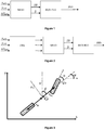
- the figure 3 diagrams the “bicycle” model, and the angles used for this embodiment.
- G represents the center of inertia of the vehicle.
- l f and l r represent the distance between the center of gravity G and the front and rear axles respectively.
- the reference system is defined by the coordinate system (x, y) which corresponds to the Lambert coordinate system.
- v is the speed of the vehicle.
- v f and v r are respectively the speed of the front and rear wheel.
- ⁇ is the lateral slip angle.
- ⁇ f and ⁇ r (not shown) correspond to the lateral slip angles of the front and rear wheels, respectively.
- ⁇ is the yaw angle.
- v L and v T are the projections of the vehicle speed in the frame associated with the vehicle chassis.
- ⁇ i 180 ⁇ ⁇ tan - 1 x GPS i - x GPS i - 1 y GPS i - y GPS i - 1
- v x i x GPS i - x GPS i - 1 T e
- v y i y GPS i - y GPS i - 1 T e
- ⁇ i tan - 1 ⁇ i ⁇ l r + l f v L i
- the position and the altitude of the vehicle are measured, and the slip parameter determined by the dynamic model is the longitudinal slip rate SR.
- the longitudinal slip rate SR can be determined by means of a mapping function of the coefficient of adhesion ⁇ of the vehicle and of meteorological conditions (state of the road).
- the figure 4 is an example of a map representing several curves of the coefficient of adhesion ⁇ as a function of the longitudinal slip rate SR for several meteorological conditions: D for dry roads, W for wet roads, S for snowy roads, and I for frozen roads.
- the meteorological conditions can be indicated by the user, or can be known by the geolocation system, in particular by connection to the Internet. Alternatively, the weather conditions can be known by sensors present on the vehicle.
- a vehicle dynamic model which relates the coefficient of adhesion to the position and to the altitude of the vehicle, then by means of a map, the longitudinal slip rate SR is deduced therefrom.
- the method according to the invention is not limited to the model described below, other models can be implemented, in particular models taking into account the width of the vehicle.
- At least one sliding parameter of the vehicle is determined by means of the dynamic model constructed in the preceding step and by means of the measurements (preprocessed or not) carried out previously.
- two slip parameters are determined: the lateral slip angle ⁇ and the longitudinal slip rate SR (cf. figures 1 and 2 ). This determination of the two slip parameters can be carried out on the basis of measurements of the position and the altitude.
- the tire slip is estimated by a mapping depending on two parameters: the grip coefficient ⁇ and the determined slip angle ⁇ .
- This mapping may depend on the condition of the pavement, in particular it is very different if the road is dry or wet (this which can be estimated from the weather), and the condition of the tires: their pressure and wear.
- a single sliding parameter is determined: the lateral sliding angle ⁇ . This determination can be made on the basis of position measurements.
- a single slip parameter is determined: the longitudinal slip rate SR. This determination can be made on the basis of altitude measurements, or on the basis of position and altitude measurements.
- the dangerous driving indicator can take the form of a value, a note ...
- the comparison of the slip parameters (or their derivatives) with thresholds makes it possible to determine whether the driver is often in limit conditions of adhesion, for which the loss experience increases.
- the indicator may consist of the number or frequency of the threshold being exceeded.
- the indicator can be an average value or a score (for example out of 10) representative of the different numbers and / or frequencies calculated for each slip parameter.
- this information can be recorded and / or transmitted to the driver (or to any other person) by means of a display.
- This recording and / or display can be carried out on board the vehicle: on the dashboard, on an autonomous portable device, such as a geolocation device (of the GPS type), a mobile phone (of the smartphone type, translation of the smartphone anglicism). It is also possible to save and display this indicator on a website, which the driver can consult after driving.
- this or these dangerous driving indicator (s) can be shared with an insurance, car sharing, car rental organization, a vehicle fleet manager ... so as to indicate whether their client's driving is dangerous or not, so that they can adapt their services: insurance costs, rental ...
- the method according to the invention can be used for motor vehicles. However, it can be used in the field of road transport, the field of two-wheelers, the railway field, the naval field, the aeronautical field, the field of hovercraft, and the field of amphibious vehicles ...
- the invention also relates to a computer program product which can be downloaded from a communication network and / or recorded on a medium readable by a computer and / or executable by a processor or a server.
- This program comprises program code instructions for implementing the method as described above, when the program is executed on a computer or a mobile phone.
- the objective of these examples is to compare the real slip measured with the estimate made according to the method described above.
- the tests consist of three "Full Foot” type accelerations in 1st, 2nd and 3rd gear, as illustrated on the figures 5a to 5d , which respectively represent the vehicle speed v vh , the RBV gearbox ratio, the engine speed N e , and the position of the accelerator pedal P acc .
- the acceleration of the vehicle is maximum since the heat engine is used at its maximum torque.
- longitudinal sliding is inevitable.
Description
La présente invention concerne le domaine des véhicules, plus particulièrement le domaine de la conduite de véhicules afin de limiter les situations de conduites dangereuses.The present invention relates to the field of vehicles, more particularly to the field of driving vehicles in order to limit dangerous driving situations.
Depuis toujours, les conducteurs et les pouvoirs publics souhaitent diminuer le nombre d'accidents et par conséquent les conduites à risque.Drivers and public authorities have always wanted to reduce the number of accidents and therefore risky driving.
Par ailleurs, les compagnies d'assurance automobile ont de tout temps cherché à évaluer la sinistralité de leurs assurés, c'est-à-dire la probabilité d'avoir un accident. La connaissance de cette sinistralité peut permettre aux assurances d'adapter leurs prestations à chaque conducteur. Cette évaluation était historiquement réalisée sur des critères purement statistiques, comme la tranche d'âge ou le type de véhicule conduit.In addition, automobile insurance companies have always sought to assess the loss experience of their policyholders, that is to say the probability of having an accident. Knowledge of this loss experience can allow insurance companies to adapt their services to each driver. This evaluation was historically carried out on purely statistical criteria, such as the age group or the type of vehicle driven.
De nos jours, l'émergence des véhicules et des objets connectés rend possible la qualification de la dangerosité de la conduite à partir de mesures. En effet, il suffit d'un boîtier autonome, d'un téléphone intelligent, d'une connexion au réseau de bord du véhicule... pour disposer de la position et donc de la vitesse et de l'accélération du véhicule. Dans ce contexte, de nouvelles méthodes d'évaluation de la sinistralité sont possibles.Nowadays, the emergence of vehicles and connected objects makes it possible to qualify the dangerousness of driving from measurements. In fact, all you need is an autonomous box, a smart phone, a connection to the vehicle's on-board network ... to have the position and therefore the speed and acceleration of the vehicle. In this context, new methods of assessing claims are possible.
La méthode d'évaluation la plus courante consiste à mettre des seuils sur la valeur maximale de l'accélération du véhicule. Par exemple, la demande brevet
Côté académique, la modélisation de la dynamique du véhicule est un sujet bien connu et les publications sont nombreuses. Les ouvrages suivants illustrent une telle modélisation :
-
Kiencke U., & Nielsen L. Automotive Control Systems. For Engine, Driveline, and Vehicle, Springer 2000 -
Rajamani R., Vehicle Control and Dynamics, Springer Science and Business Media, 2011
-
Kiencke U., & Nielsen L. Automotive Control Systems. For Engine, Driveline, and Vehicle, Springer 2000 -
Rajamani R., Vehicle Control and Dynamics, Springer Science and Business Media, 2011
Mais, si ces approches de modélisation sont très représentatives de la dynamique du véhicule, elles ne sont pas adaptées à une utilisation pour qualifier la dangerosité de la conduite. En effet, elles demandent un trop grand nombre de paramètres décrivant le véhicule et surtout un trop grand nombre de mesures. Elles sont donc adaptées uniquement pour des travaux de recherches sur lesquels les véhicules sont abondamment instrumentés mais ne conviennent pas à des véhicules de série sur lesquels la définition technique capteur est réduite au minimum.However, if these modeling approaches are very representative of the dynamics of the vehicle, they are not suitable for use to qualify the dangerousness of driving. Indeed, they require too many parameters describing the vehicle and above all too many measurements. They are therefore only suitable for research work on which the vehicles are abundantly instrumented but are not suitable for production vehicles on which the technical definition of the sensor is reduced to a minimum.
La demande de brevet
La demande de brevet
La présente invention consiste à déterminer au moins un indicateur de conduite dangereuse au moyen d'un modèle physique simple basé sur la dynamique du véhicule. Selon l'invention, le modèle de dynamique du véhicule permet de déterminer un paramètre de glissement du véhicule, qui est utilisé pour déduire un indicateur de conduite dangereuse représentatif. L'un des objectifs du procédé selon l'invention est d'obtenir une méthode plus représentative et plus robuste que les approches heuristiques basés simplement sur des seuils d'accélération.The present invention consists in determining at least one dangerous driving indicator by means of a simple physical model based on the dynamics of the vehicle. According to the invention, the vehicle dynamics model makes it possible to determine a vehicle slip parameter, which is used to derive a representative dangerous driving indicator. One of the objectives of the method according to the invention is to obtain a method which is more representative and more robust than heuristic approaches based simply on acceleration thresholds.
L'invention concerne un procédé de détermination d'au moins un indicateur de dangerosité de la conduite d'un véhicule selon la revendication 1. Pour ce procédé, on réalise les étapes suivantes :
- a) on mesure la position et/ou l'altitude dudit véhicule ;
- b) on construit un modèle de dynamique du véhicule qui relie la position et/ou l'altitude dudit véhicule à au moins un paramètre de glissement du véhicule ;
- c) on détermine au moins un paramètre de glissement du véhicule au moyen dudit modèle de dynamique et de ladite position et/ou altitude mesurée ; et
- d) on détermine au moins un indicateur de dangerosité de la conduite du véhicule au moyen dudit paramètre de glissement.
- a) the position and / or altitude of said vehicle is measured;
- b) a vehicle dynamics model is constructed which relates the position and / or the altitude of said vehicle to at least one sliding parameter of the vehicle;
- c) at least one vehicle slip parameter is determined by means of said dynamic model and said measured position and / or altitude; and
- d) at least one indicator of the dangerousness of driving the vehicle is determined by means of said slip parameter.
Selon l'invention, on mesure la position et/ou l'altitude dudit véhicule au moyen d'un système de géolocalisation.According to the invention, the position and / or the altitude of said vehicle is measured by means of a geolocation system.
Conformément à une mise en œuvre de réalisation de l'invention, préalablement à l'étape de détermination d'un paramètre de glissement, on réalise un prétraitement desdites mesures de position et/ou d'altitude, notamment au moyen d'un sur-échantillonnage et/ou d'un filtrage.In accordance with one implementation of the invention, prior to the step of determining a slip parameter, a preprocessing of said position and / or altitude measurements is carried out, in particular by means of an over- sampling and / or filtering.
Avantageusement, ledit modèle de dynamique du véhicule est un modèle dans lequel on néglige la largeur du véhicule.Advantageously, said model of vehicle dynamics is a model in which the width of the vehicle is neglected.
Selon un mode de réalisation, ledit au moins paramètre de glissement du véhicule est l'angle de glissement latéral β du véhicule et/ou le taux de glissement longitudinal SR du véhicule.According to one embodiment, said at least vehicle slip parameter is the lateral slip angle β of the vehicle and / or the longitudinal slip rate SR of the vehicle.
De préférence, ledit modèle de dynamique du véhicule détermine ledit angle de glissement latéral β par une formule du type : ![]()
![]()
![]()
![]()
![]()
![]()
![]()
- xGPS, yGPS : les coordonnées du véhicule dans le repère de Lambert, correspondant à la position mesurée du véhicule,
- altGPS : l'altitude mesurée du véhicule,
- i : l'instant du calcul,
- aveh : l'accélération du véhicule,
- Mvehicule : la masse du véhicule,
- ρair : la masse volumique de l'air,
- S : la surface frontale du véhicule,
- Cx : le coefficient de trainée aérodynamique frontal du véhicule,
- k : le coefficient de frottement visqueux,
- CRR : le coefficient de résistance au roulement du véhicule, et
- g : l'accélération de la pesanteur.
- x GPS , y GPS : the coordinates of the vehicle in the Lambert coordinate system, corresponding to the measured position of the vehicle,
- alt GPS : the measured altitude of the vehicle,
- i: the moment of calculation,
- a veh : vehicle acceleration,
- M vehicle : the mass of the vehicle,
- ρ air : the density of the air,
- S : the front surface of the vehicle,
- C x : the frontal aerodynamic drag coefficient of the vehicle,
- k : the viscous coefficient of friction,
- C RR : the vehicle's rolling resistance coefficient, and
- g: the acceleration of gravity.
Selon l'invention, on détermine ledit indicateur de dangerosité par détermination du nombre et/ou de la fréquence de dépassements d'au moins un seuil par ledit paramètre de glissement.According to the invention, said dangerousness indicator is determined by determining the number and / or the frequency of exceeding of at least one threshold by said sliding parameter.
Conformément à un mode de réalisation, on affiche et/ou on enregistre ledit au moins un indicateur de dangerosité pendant la conduite du véhicule.According to one embodiment, said at least one dangerousness indicator is displayed and / or recorded while driving the vehicle.
Avantageusement, on affiche et/ou on enregistre ledit au moins un indicateur de dangerosité sur le tableau de bord dudit véhicule, sur un site internet, ou sur un dispositif portatif autonome, tel qu'un système de géolocalisation ou un téléphone portable.Advantageously, said at least one danger indicator is displayed and / or recorded on the dashboard of said vehicle, on a website, or on an autonomous portable device, such as a geolocation system or a mobile phone.
Préférentiellement, ledit modèle de dynamique du véhicule prend en compte au moins une des conditions suivantes : l'état de la chaussée, les conditions météorologiques, la pression et l'état d'usure des pneumatiques du véhicule, notamment au moyen d'une cartographie.Preferably, said vehicle dynamic model takes into account at least one of the following conditions: the condition of the roadway, the weather conditions, the pressure and the state of wear of the tires of the vehicle, in particular by means of a map .
L'invention concerne également un procédé de commande d'un véhicule. Pour ce procédé, on réalise les étapes suivantes :
- a) on détermine au moins un indicateur de dangerosité selon l'une des caractéristiques précédentes ; et
- b) on adapte la commande dudit véhicule en fonction dudit indicateur de dangerosité.
- a) at least one indicator of dangerousness is determined according to one of the preceding characteristics; and
- b) the control of said vehicle is adapted as a function of said danger indicator.
En outre, l'invention concerne un produit programme d'ordinateur téléchargeable depuis un réseau de communication et/ou enregistré sur un support lisible par ordinateur et/ou exécutable par un processeur ou un serveur, comprenant des instructions de code de programme pour la mise en œuvre du procédé selon l'une des caractéristiques précédentes, lorsque ledit programme est exécuté sur un ordinateur ou sur un téléphone portable.Furthermore, the invention relates to a computer program product downloadable from a communication network and / or recorded on a medium readable by a computer and / or executable by a processor or a server, comprising program code instructions for the implementation. implementing the method according to one of the preceding characteristics, when said program is executed on a computer or on a portable telephone.
D'autres caractéristiques et avantages du procédé selon l'invention, apparaîtront à la lecture de la description ci-après d'exemples non limitatifs de réalisations, en se référant aux figures annexées et décrites ci-après.
- La
figure 1 illustre les étapes du procédé de détermination d'un indicateur de dangerosité de la conduite selon un mode de réalisation de l'invention. - La
figure 2 illustre les étapes du procédé de détermination d'un indicateur de dangerosité de la conduite selon un autre mode de réalisation de l'invention. - La
figure 3 illustre un paramétrage géométrique du véhicule pour un modèle de dynamique. - La
figure 4 illustre une cartographie du taux de glissement longitudinal du véhicule en fonction du coefficient d'adhérence et de conditions météorologiques. - Les
figures 5a à 5d représentent respectivement des courbes de la vitesse, du rapport de boite de vitesse, du régime moteur et de la position de la pédale d'accélération en fonction du temps, pour lesquels des essais sont réalisés. - La
figure 6 illustre des courbes du ratio de glissement longitudinal estimé et du ratio de glissement mesuré en fonction du temps, pour les essais selon lafigure 5 ,. - La
figure 7 illustre les courbes du ratio de glissement longitudinal en fonction du temps et de la pente.
- The
figure 1 illustrates the steps of the method for determining a driving hazard indicator according to one embodiment of the invention. - The
figure 2 illustrates the steps of the method for determining a driving danger indicator according to another embodiment of the invention. - The
figure 3 illustrates a geometric configuration of the vehicle for a dynamic model. - The
figure 4 illustrates a map of the longitudinal slip rate of the vehicle as a function of the coefficient of adhesion and weather conditions. - The
figures 5a to 5d respectively represent curves of the speed, the gearbox ratio, the engine speed and the position of the accelerator pedal as a function of time, for which tests are carried out. - The
figure 6 illustrates curves of the estimated longitudinal slip ratio and of the measured slip ratio as a function of time, for tests according to thefigure 5 ,. - The
figure 7 illustrates the curves of the longitudinal slip ratio as a function of time and slope.
La présente invention concerne un procédé de détermination d'au moins un indicateur de dangerosité de la conduite d'un véhicule. Une conduite est qualifiée de dangereuse, si elle peut présenter un risque d'accident, quelle que soit la cause de ce comportement risqué. L'indicateur de dangerosité (appelé également indicateur de conduite dangereuse) permet de quantifier cette dangerosité. Selon l'invention, l'indicateur de dangerosité est déterminé sur la base des conditions de limites d'adhérence du véhicule, c'est-à-dire lors du glissement du véhicule. En effet, dans ces conditions, la sinistralité augmente. Cet indicateur peut être utilisé par le conducteur pour améliorer sa conduite et la rendre plus sûre, ou par un contrôleur qui peut adapter automatiquement la commande du véhicule, ou par un organisme d'assurance ou de location/partage de véhicules afin d'avoir des informations sur la conduite de leur client.The present invention relates to a method for determining at least one indicator of the dangerousness of driving a vehicle. Driving is classified as dangerous if it may present a risk of accident, whatever the cause of this risky behavior. The dangerousness indicator (also called dangerous driving indicator) makes it possible to quantify this dangerousness. According to the invention, the dangerousness indicator is determined on the basis of the grip limit conditions of the vehicle, that is to say when the vehicle slips. In fact, under these conditions, claims are increasing. This indicator can be used by the driver to improve his driving and make it safer, or by a controller that can automatically adapt the vehicle control, or by an insurance or rental / vehicle sharing organization in order to have information about their client's conduct.
Dans la suite de la description, on utilise les notations suivantes :
Pour ces notations, l'indice r indique ce qui se réfère à la roue arrière, et l'indice f ce qui se réfère à la roue avant. Les projections sur les axes x et y du repère de Lambert sont notées par les indices x et y.For these notations, the index r indicates what refers to the rear wheel, and the index f what refers to the front wheel. The projections on the x and y axes of the Lambert coordinate system are denoted by the x and y indices.
Le procédé selon l'invention comprend les étapes suivantes (l'étape de prétraitement étant optionnelle) :
- 1) Mesure de la position et/ou l'altitude
- 2) Prétraitement des mesures
- 3) Construction du modèle de dynamique du véhicule
- 4) Détermination d'un paramètre de glissement
- 5) Détermination d'un indicateur de dangerosité
- 1) Position and / or altitude measurement
- 2) Preprocessing of measurements
- 3) Construction of the vehicle dynamics model
- 4) Determination of a sliding parameter
- 5) Determination of a dangerousness indicator
Ces étapes peuvent être réalisées en temps réel, lors du déplacement du véhicule.These steps can be performed in real time, while the vehicle is moving.
La
La
Lors de cette étape, il s'agit de déterminer la position et/ou l'altitude du véhicule. De préférence, la position et l'altitude sont mesurées, afin d'obtenir plusieurs paramètres de glissement, ce qui permet de déterminer un indicateur de dangerosité fiable. Toutefois, pour simplifier le procédé selon l'invention, seule la position, ou seule l'altitude du véhicule peut être mesurée.During this step, it is a question of determining the position and / or the altitude of the vehicle. Preferably, the position and the altitude are measured, in order to obtain several slip parameters, which makes it possible to determine a reliable indicator of dangerousness. However, for to simplify the method according to the invention, only the position, or only the altitude of the vehicle can be measured.
Selon un mode de réalisation de l'invention, les mesures (position et/ou altitude) sont réalisées au moyen d'un système de géolocalisation, tel qu'un système de positionnement par satellite, tel que le système GPS (de l'anglais Global Positioning System), le système Galileo... Le système de géolocalisation peut, avantageusement, être inclus dans un téléphone portable, du type téléphone intelligent (de l'anglais « Smartphone »).According to one embodiment of the invention, the measurements (position and / or altitude) are carried out by means of a geolocation system, such as a satellite positioning system, such as the GPS system. Global Positioning System), the Galileo system, etc. The geolocation system can advantageously be included in a mobile phone, of the smart phone type (standing for “Smartphone”).
La prise en compte de l'altitude permet notamment une meilleure estimation du glissement, ce qui permet d'obtenir un indicateur de dangerosité de conduite plus fiable.Taking altitude into account allows in particular a better estimate of the slip, which makes it possible to obtain a more reliable indicator of dangerous driving.
De manière avantageuse, la position du véhicule correspond à des coordonnées du véhicule exprimées dans le repère de Lambert, qui est un repère universel : il s'agit de la projection officielle utilisée pour les cartes.Advantageously, the position of the vehicle corresponds to coordinates of the vehicle expressed in the Lambert frame of reference, which is a universal frame of reference: this is the official projection used for the maps.
Cette étape est optionnelle, elle est réalisée avant la détermination d'au moins un paramètre de glissement (cf.
Les mesures disponibles (position et/ou altitude) pour qualifier la conduite peuvent provenir d'un boitier connecté, d'un téléphone intelligent.... En conséquence, leur qualité est variable et parfois perfectible et il est préférable d'en assurer un prétraitement avant de pouvoir les utiliser, afin d'obtenir un indicateur fiable. Ce prétraitement peut être variable, car dépendant de la qualité des données d'entrée. Dans le cas le plus courant, le prétraitement des mesures peut consister en un sur-échantillonnage des mesures, puis un filtrage (par exemple au moyen d'un filtre passe-bas). De manière alternative, l'étape de prétraitement peut consister seulement en un sur-échantillonnage, ou seulement en un filtrage.The measurements available (position and / or altitude) to qualify driving can come from a connected box, a smart phone, etc. As a result, their quality is variable and sometimes perfectible and it is preferable to ensure a pretreatment before they can be used, in order to obtain a reliable indicator. This preprocessing can be variable, since it depends on the quality of the input data. In the most common case, the preprocessing of the measurements can consist of an oversampling of the measurements, then filtering (for example by means of a low-pass filter). Alternatively, the preprocessing step can consist only of over-sampling, or only of filtering.
On appelle modèle de dynamique du véhicule, un modèle qui relie au moins un paramètre de glissement (des pneumatiques du véhicule) à la position et/ou l'altitude du véhicule. Le modèle prend en compte la dynamique du véhicule (vitesse, accélération...) pour déterminer le glissement du véhicule, c'est-à-dire un mouvement non désiré et non contrôlé du véhicule.The term vehicle dynamics model is used to refer to a model which relates at least one sliding parameter (of the tires of the vehicle) to the position and / or the altitude of the vehicle. The model takes into account the dynamics of the vehicle (speed, acceleration ...) to determine the slip of the vehicle, that is to say an unwanted and uncontrolled movement of the vehicle.
Selon un mode de réalisation de l'invention, le modèle de dynamique du véhicule prend en compte au moins une, de préférence toutes, des conditions suivantes : l'état de la chaussée, les conditions météorologiques, la pression et l'état d'usure des pneumatiques du véhicule, notamment au moyen d'une cartographie. Cette cartographie peut relier notamment le paramètre de glissement au coefficient d'adhérence des pneumatiques. Ainsi, l'indicateur de conduite dangereuse est rendu plus représentatif de la dangerosité.According to one embodiment of the invention, the vehicle dynamic model takes into account at least one, preferably all, of the following conditions: the condition of the roadway, the weather conditions, the pressure and the condition of wear of vehicle tires, in particular by means of mapping. This mapping can link in particular the slip parameter to the coefficient of adhesion of the tires. Thus, the dangerous driving indicator is made more representative of the dangerousness.
Un paramètre de glissement des pneumatiques du véhicule peut être l'angle de glissement latéral du véhicule, noté β. L'angle de glissement latéral correspond à l'angle formé entre le vecteur vitesse du véhicule et l'axe longitudinal du véhicule.A parameter of the slip of the tires of the vehicle may be the lateral slip angle of the vehicle, denoted β . The lateral slip angle corresponds to the angle formed between the speed vector of the vehicle and the longitudinal axis of the vehicle.
Un autre paramètre de glissement des pneumatiques du véhicule peut être le taux de glissement longitudinal, noté SR. Le taux de glissement longitudinal traduit le glissement du pneumatique de la roue par rapport au sol. Ce taux de glissement dépend notamment du coefficient d'adhérence du pneumatique sur le sol.Another parameter of the slip of the tires of the vehicle may be the rate of longitudinal slip, denoted SR. The longitudinal slip rate reflects the slip of the tire of the wheel relative to the ground. This slip rate depends in particular on the coefficient of adhesion of the tire on the ground.
Selon un mode de réalisation, on suppose que les roues restent au contact d'un sol plat. De plus, on suppose que les suspensions sont rigides, ce qui revient à négliger le roulis et le tangage. En outre, on peut modéliser le véhicule par un modèle de type « bicyclette ». Cela revient à considérer que la largeur du véhicule est négligeable, et par conséquent que les roues gauches et droites ont un comportement similaire.According to one embodiment, it is assumed that the wheels remain in contact with a flat ground. In addition, it is assumed that the suspensions are rigid, which amounts to neglecting the roll and pitch. In addition, the vehicle can be modeled by a “bicycle” type model. This amounts to considering that the width of the vehicle is negligible, and consequently that the left and right wheels have a similar behavior.
La
Selon une variante de réalisation de l'invention, la position est mesurée et le paramètre de glissement déterminé par le modèle de dynamique est l'angle de glissement latéral β. Pour cette variante, on peut déterminer l'angle de glissement latéral β par une formule du type : ![]()
- i :
- l'instant du calcul,
- vfy :
- la projection sur l'axe y de la vitesse de la roue avant,
- vry :
- la projection sur l'axe y de la vitesse de la roue arrière, et
- vL :
- la projection sur l'axe longitudinal du véhicule de la vitesse du véhicule,
- i:
- the moment of calculation,
- v fy :
- the projection on the y axis of the speed of the front wheel,
- v ry :
- the projection on the y axis of the speed of the rear wheel, and
- v L :
- the projection on the longitudinal axis of the vehicle of the vehicle speed,
Pour cette estimation de l'angle de glissement latéral β, on peut réaliser la suite d'étapes suivantes :For this estimate of the lateral slip angle β , the following series of steps can be carried out:
Dans cette section, le calcul de l'angle de braquage des roues avant α est détaillé.In this section, the calculation of the steering angle of the front wheels α is detailed.
Le calcul de l'angle de lacet, à partir des coordonnées (position), peut être obtenu à partir de l'équation suivante : ![]()
![]()
La vitesse angulaire du véhicule peut être donnée par une formule du type : ![]()
![]()
Les projections vx et vy de la vitesse v du véhicule dans le référentiel (x,y) peuvent être données par : ![]()
![]()
![]()
![]()
Les projections vL et vT de la vitesse v dans le référentiel du châssis du véhicule peuvent être données par : ![]()
![]()
![]()
![]()
L'angle de braquage peut alors être calculé : ![]()
![]()
Dans cette section, le calcul de l'angle de glissement latéral β est détaillé. La méthode choisie consiste à prendre la moyenne l'angle de glissement latéral des roues avant et arrière.In this section, the calculation of the lateral slip angle β is detailed. The method chosen is to take the average side slip angle of the front and rear wheels.
Pour ce faire, on calcule les projections vfy et vry sur l'axe y des vitesses des roues avant et arrière vf et vr respectivement : ![]()
![]()
![]()
![]()
On en déduit β par une équation de la forme : ![]()
![]()
Ainsi, en combinant les équation, on obtient un modèle de dynamique du véhicule qui relie l'angle de glissement latéral β à la position du véhicule.Thus, by combining the equations, we obtain a vehicle dynamics model which relates the lateral slip angle β to the position of the vehicle.
Selon une variante de réalisation (pouvant être combinée à la variante précédemment décrite), on mesure la position et l'altitude du véhicule, et le paramètre de glissement déterminé par le modèle de dynamique est le taux de glissement longitudinal SR. Pour cette variante de réalisation, on peut déterminer le taux de glissement longitudinal SR au moyen d'une cartographie fonction du coefficient d'adhérence µ du véhicule et de conditions météorologiques (état de la route).According to a variant embodiment (which can be combined with the variant described above), the position and the altitude of the vehicle are measured, and the slip parameter determined by the dynamic model is the longitudinal slip rate SR. For this variant embodiment, the longitudinal slip rate SR can be determined by means of a mapping function of the coefficient of adhesion μ of the vehicle and of meteorological conditions (state of the road).
La
Pour une estimation du coefficient d'adhérence µ, on peut mettre en œuvre les étapes suivantes :For an estimate of the coefficient of adhesion µ , the following steps can be implemented:
Dans cette section, le calcul de l'angle de la pente θ est détaillé.In this section, the calculation of the angle of the slope θ is detailed.
La distance parcourue à chaque instant est donnée par : ![]()
![]()
La variation d'altitude peut se calculer simplement via l'altitude issue des mesures : ![]()
![]()
En conséquence, la pente instantanée peut s'obtenir par : ![]()
![]()
Selon une conception particulière de l'invention, à ce stade on peut appliquer un filtre de type moyenne glissante sur la pente pour capter seulement les variations significatives et limiter l'impact du bruit.According to a particular design of the invention, at this stage it is possible to apply a filter of the sliding average type on the slope in order to capture only the significant variations and limit the impact of noise.
L'angle de la pente peut être estimé par une équation de la forme : ![]()
![]()
Pour calculer le coefficient d'adhérence µ, on calcule la force de traction au niveau du contact sol roue Fdriving et la force de gravité normale Fz ![]()
![]()
![]()
![]()
Avec aveh l'accélération instantanée du véhicule, et Fres la résultante des forces de frottements qui s'appliquent sur le véhicule, cette résultante étant donnée par la relation suivante appelée « loi de route ». Ce terme s'exprime directement en fonction de la vitesse et des caractéristiques du véhicule ![]()
![]()
L'accélération instantanée du véhicule aveh peut être obtenue (selon les capteurs disponibles) à partir d'un accéléromètre et/ou à partir de la vitesse véhicule estimée à partir de la position mesurée. Selon un exemple, elle peut être estimée à partir d'une équation de la forme : ![]()
![]()
On peut en déduire le coefficient d'adhérence µ par une équation du type : ![]()
![]()
Ainsi, en combinant les équations, on obtient un modèle de dynamique du véhicule qui relie le coefficient d'adhérence à la position et à l'altitude du véhicule, puis au moyen d'une cartographie on en déduit le taux de glissement longitudinal SR.Thus, by combining the equations, a vehicle dynamic model is obtained which relates the coefficient of adhesion to the position and to the altitude of the vehicle, then by means of a map, the longitudinal slip rate SR is deduced therefrom.
Le procédé selon l'invention n'est pas limité au modèle décrit ci-dessous, d'autres modèles peuvent être mis en œuvre, notamment des modèles prenant en compte la largeur du véhicule.The method according to the invention is not limited to the model described below, other models can be implemented, in particular models taking into account the width of the vehicle.
Lors de cette étape, on détermine au moins un paramètre de glissement du véhicule au moyen du modèle de dynamique construit à l'étape précédente et au moyen des mesures (prétraitées ou non) réalisées précédemment.During this step, at least one sliding parameter of the vehicle is determined by means of the dynamic model constructed in the preceding step and by means of the measurements (preprocessed or not) carried out previously.
Selon un mode de réalisation de l'invention, lors de cette étape, on détermine deux paramètres de glissement : l'angle de glissement latéral β et le taux de glissement longitudinal SR (cf.
A partir de l'angle de glissement latéral β déterminé, on estime le glissement des pneumatiques par une cartographie dépendant de deux paramètres : le coefficient d'adhérence µ et l'angle de glissement déterminé β. Cette cartographie peut dépendre de l'état de la chaussée, en particulier elle est très différente si la route est sèche ou humide (ce qui peut être estimé à partir de la météo), et de l'état des pneus : de leur pression et de leur usure.From the determined lateral slip angle β , the tire slip is estimated by a mapping depending on two parameters: the grip coefficient µ and the determined slip angle β . This mapping may depend on the condition of the pavement, in particular it is very different if the road is dry or wet (this which can be estimated from the weather), and the condition of the tires: their pressure and wear.
Selon une alternative, lors de cette étape, on détermine un seul paramètre de glissement : l'angle de glissement latéral β. Cette détermination peut être réalisée sur la base de mesures de la position.According to an alternative, during this step, a single sliding parameter is determined: the lateral sliding angle β . This determination can be made on the basis of position measurements.
Alternativement, lors de cette étape, on détermine un seul paramètre de glissement : le taux de glissement longitudinal SR. Cette détermination peut être réalisée sur la base de mesures de l'altitude, ou sur la base de mesures de la position et de l'altitude.Alternatively, during this step, a single slip parameter is determined: the longitudinal slip rate SR. This determination can be made on the basis of altitude measurements, or on the basis of position and altitude measurements.
Il s'agit de déterminer au moins un indicateur de dangerosité de conduite à partir du ou des paramètres de glissement déterminés à l'étape précédente. L'indicateur de conduite dangereuse peut prendre la forme d'une valeur, d'une note...This involves determining at least one indicator of driving dangerousness from the slip parameter or parameters determined in the previous step. The dangerous driving indicator can take the form of a value, a note ...
Conformément à une variante de réalisation de l'invention, l'indicateur de conduite dangereuse peut être déterminé en mettant en œuvre les étapes suivantes :
- on choisit au moins un seuil (au moins un seuil par paramètre) de conduite dangereuse pour le(s) paramètre(s) de glissement ou leurs dérivés ;
- on détermine si le(s) paramètre(s) de glissement ou leur dérivés dépasse(nt) le seuil choisi ;
- on quantifie le nombre de fois et/ou la fréquence (temporelle ou kilométrique) pour lesquels le(s) paramètre(s) de glissement ou leur dérivés ont dépassé le seuil choisi ; et
- on déduit du nombre et/ou de la fréquence un indicateur de dangerosité.
- at least one dangerous driving threshold (at least one threshold per parameter) is chosen for the slip parameter (s) or their derivatives;
- it is determined whether the sliding parameter (s) or their derivatives exceed (s) the selected threshold;
- the number of times and / or the frequency (temporal or kilometric) for which the slip parameter (s) or their derivatives have exceeded the chosen threshold is quantified; and
- an indicator of dangerousness is deduced from the number and / or the frequency.
En effet, la comparaison des paramètres de glissement (ou leurs dérivés) avec des seuils permet de déterminer si le conducteur se trouve souvent dans des conditions limites d'adhérence, pour lesquels la sinistralité augmente.Indeed, the comparison of the slip parameters (or their derivatives) with thresholds makes it possible to determine whether the driver is often in limit conditions of adhesion, for which the loss experience increases.
L'indicateur peut consister au nombre ou à la fréquence de dépassement de seuil. Alternativement l'indicateur peut être une valeur moyenne ou une note (par exemple sur 10) représentative des différents nombres et/ou fréquences calculés pour chaque paramètre de glissement.The indicator may consist of the number or frequency of the threshold being exceeded. Alternatively, the indicator can be an average value or a score (for example out of 10) representative of the different numbers and / or frequencies calculated for each slip parameter.
Une fois le ou les indicateurs de dangerosité de conduite déterminés, on peut enregistrer et/ou transmettre cette information au conducteur (ou à tout autre personne) au moyen d'un affichage. Cet enregistrement et/ou affichage peut être réalisé à bord du véhicule : sur le tableau de bord, sur un dispositif portatif autonome, tel qu'un appareil de géolocalisation (de type GPS), un téléphone portable (de type ordiphone, traduction de l'anglicisme smartphone). Il est également possible d'enregistrer et d'afficher cet indicateur sur un site internet, que le conducteur peut consulter postérieurement à sa conduite. De plus, ce ou ces indicateurs de conduite dangereuse peuvent être partagés avec un organisme d'assurance, de partage de voitures, de locations de voitures, un gestionnaire de flotte de véhicules ... de manière à indiquer si la conduite de leur client est dangereuse ou non, afin qu'ils puissent adapter leur prestations : frais d'assurance, de location...Once the driving danger indicator (s) have been determined, this information can be recorded and / or transmitted to the driver (or to any other person) by means of a display. This recording and / or display can be carried out on board the vehicle: on the dashboard, on an autonomous portable device, such as a geolocation device (of the GPS type), a mobile phone (of the smartphone type, translation of the smartphone anglicism). It is also possible to save and display this indicator on a website, which the driver can consult after driving. In addition, this or these dangerous driving indicator (s) can be shared with an insurance, car sharing, car rental organization, a vehicle fleet manager ... so as to indicate whether their client's driving is dangerous or not, so that they can adapt their services: insurance costs, rental ...
La présente invention concerne également un procédé de commande d'un véhicule, dans lequel on réalise les étapes suivantes :
- on détermine au moins un indicateur de dangerosité au moyen du procédé précédemment décrit ; et
- on adapte la commande du véhicule en fonction de l'indicateur de dangerosité : cette adaptation peut être réalisée directement par le conducteur qui se rend compte de la dangerosité de sa conduite, ou peut être réalisée par un contrôleur du véhicule qui limite les situations dangereuses.
- at least one dangerousness indicator is determined by means of the method described above; and
- the vehicle control is adapted according to the danger indicator: this adaptation can be carried out directly by the driver who realizes the dangerousness of his driving, or can be carried out by a vehicle controller who limits dangerous situations.
Le procédé selon l'invention peut être utilisé pour les véhicules automobiles. Toutefois il peut être utilisé dans le domaine du transport routier, le domaine des deux-roues, le domaine ferroviaire, le domaine naval, le domaine aéronautique, le domaine des aéroglisseurs, et le domaine des véhicules amphibies...The method according to the invention can be used for motor vehicles. However, it can be used in the field of road transport, the field of two-wheelers, the railway field, the naval field, the aeronautical field, the field of hovercraft, and the field of amphibious vehicles ...
L'invention concerne par ailleurs un produit programme d'ordinateur téléchargeable depuis un réseau de communication et/ou enregistré sur un support lisible par ordinateur et/ou exécutable par un processeur ou un serveur. Ce programme comprend des instructions de code de programme pour la mise en œuvre du procédé tel que décrit ci-dessus, lorsque le programme est exécuté sur un ordinateur ou un téléphone portable.The invention also relates to a computer program product which can be downloaded from a communication network and / or recorded on a medium readable by a computer and / or executable by a processor or a server. This program comprises program code instructions for implementing the method as described above, when the program is executed on a computer or a mobile phone.
L'objectif de ces exemples est de comparer le glissement réel mesuré avec l'estimation réalisée suivant le procédé précédemment décrit.The objective of these examples is to compare the real slip measured with the estimate made according to the method described above.
Les essais consistent en trois accélérations de type « Pied à Fond » en 1ère, 2ème et 3ème vitesse, comme illustrées sur les
Les résultats de l'estimation EST selon le procédé selon l'invention, et des mesures MES du glissement longitudinal SR sont donnés sur la
Une des valeurs ajoutées de la présente invention est la prise en compte la pente sur l'estimation du glissement. La figure 8 montre l'impact de la pente P sur le taux de glissement longitudinal SR. Il s'agit toujours du même cas test (
Claims (14)
- Method of determining at least one dangerous driving indicator of a vehicle, in which the following steps are performed:a) the position and/or the altitude of said vehicle is/are measured;b) a dynamic model of the vehicle is constructed that links the position and/or the altitude of said vehicle to at least one slip parameter of the vehicle;c) at least one slip parameter of the vehicle is determined by means of said dynamic model and said measured position and/or altitude; andd) at least one dangerous driving indicator of the vehicle is determined by means of said slip parameter, by determining the number of times and/or frequency of exceeding at least one threshold by said slip parameter.
- Method according to Claim 1, in which the position and/or the altitude of said vehicle is/are measured by means of a geolocation system.
- Method according to one of the preceding claims, in which prior to the step of determining a slip parameter, preprocessing of said position and/or altitude measurements is performed, notably by means of oversampling and/or filtering.
- Method according to one of the preceding claims, in which said dynamic model of the vehicle is a model in which the width of the vehicle is disregarded.
- Method according to one of the preceding claims, in which said at least slip parameter of the vehicle is the lateral slip angle β of the vehicle and/or the longitudinal slip rate SR of the vehicle.
- Method according to Claim 5, in which said dynamic model of the vehicle determines said lateral slip angle β by a formula of the type:
 i : the instant of calculation,vfy : the projection on the y axis of the speed of the front wheel,vry : the projection on the y axis of the speed of the rear wheel,vL : the projection on the longitudinal axis of the vehicle of the speed of the vehicle, andx, y: the axes of the Lambert coordinate system,the projections of said speeds being a function of said position of the vehicle.
 - Method according to Claim 6, in which said projections of the speeds of said dynamic model are determined by relationships of the type:


 xGPS, yGPS : the coordinates of the vehicle in the Lambert coordinate system, corresponding to the measured position of the vehicle,i : the instant of calculation,Te : the sampling period,lf : the distance between the centre of gravity and the front wheels of the vehicle, andlr : the distance between the centre of gravity and the rear wheels of the vehicle.
 - Method according to one of Claims 5 through 7, in which said dynamic model determines the slip rate SR of the vehicle by means of a mapping function for mapping the coefficient of adhesion µ of the vehicle and weather conditions.
- Method according to Claim 8, in which said coefficient of adhesion µ of the vehicle is determined by a formula of the type:


 xGPS, yGPS : the coordinates of the vehicle in the Lambert coordinate system, corresponding to the measured position of the vehicle,altGPS : the measured altitude of the vehicle,i : the instant of calculation,aveh : the acceleration of the vehicle,Mvehicle : the mass of the vehicle,Pair : the density of the air,S : the front surface area of the vehicle,Cx : the front aerodynamic drag coefficient of the vehicle,k : the coefficient of viscous friction,v : the speed of the vehicle,CRR : the rolling resistance coefficient of the vehicle, andg : the acceleration of gravity.
 - Method according to one of the preceding claims, in which said at least one dangerous driving indicator is displayed and/or recorded while the vehicle is being driven.
- Method according to Claim 10, in which said at least one dangerous driving indicator is displayed and/or recorded on the dashboard of said vehicle, on an Internet site, or on a standalone portable device such as a geolocation system or a mobile phone.
- Method according to one of the preceding claims, in which said dynamic model of the vehicle takes into account at least one of the following conditions: the state of the highway, the weather conditions, the pressure and state of wear of the vehicle's tyres, notably by means of mapping.
- Method for controlling a vehicle, characterized in that the following steps are performed:a) at least one dangerous driving indicator is determined according to one of the preceding claims; andb) the control of said vehicle is adapted according to said dangerous driving indicator.
- Computer program product downloadable from a communication network and/or recorded on a computer-readable medium and/or executable by a processor or a server, characterized in that said computer program product includes program code instructions for implementing the method according to one of the preceding claims, when said program is executed on a computer or on a mobile phone.
Applications Claiming Priority (2)
| Application Number | Priority Date | Filing Date | Title |
|---|---|---|---|
| FR1555924A FR3037875B1 (en) | 2015-06-26 | 2015-06-26 | METHOD FOR DETERMINING A DANGEROSITY INDICATOR OF THE DRIVING OF A VEHICLE |
| PCT/EP2016/062080 WO2016206913A1 (en) | 2015-06-26 | 2016-05-27 | Method for determining a dangerous driving indicator of a vehicle |
Publications (2)
| Publication Number | Publication Date |
|---|---|
| EP3313683A1 EP3313683A1 (en) | 2018-05-02 |
| EP3313683B1 true EP3313683B1 (en) | 2020-11-25 |
Family
ID=54260910
Family Applications (1)
| Application Number | Title | Priority Date | Filing Date |
|---|---|---|---|
| EP16727400.0A Active EP3313683B1 (en) | 2015-06-26 | 2016-05-27 | Method for determining a dangerous driving indicator of a vehicle |
Country Status (4)
| Country | Link |
|---|---|
| US (1) | US10414409B2 (en) |
| EP (1) | EP3313683B1 (en) |
| FR (1) | FR3037875B1 (en) |
| WO (1) | WO2016206913A1 (en) |
Families Citing this family (2)
| Publication number | Priority date | Publication date | Assignee | Title |
|---|---|---|---|---|
| CN109733410A (en) * | 2018-12-21 | 2019-05-10 | 浙江万安科技股份有限公司 | A kind of real-time pavement identification method of ABS and system |
| CN111722626B (en) * | 2020-05-11 | 2023-07-18 | 北京经纬恒润科技股份有限公司 | Remote driving system, safety protection method and safety protection module thereof |
Family Cites Families (9)
| Publication number | Priority date | Publication date | Assignee | Title |
|---|---|---|---|---|
| US6681180B2 (en) * | 2001-01-29 | 2004-01-20 | The Board Of Trustees Of The Leland Stanford Junior University | Determination and control of vehicle sideslip using GPS |
| US20070127144A1 (en) | 2005-12-06 | 2007-06-07 | Eastman Kodak Company | Optical film and frame with high resistance to thermal distortion |
| JP4903109B2 (en) * | 2007-10-10 | 2012-03-28 | 株式会社ブリヂストン | Construction vehicle tire tread pattern selection method and construction vehicle tire tread pattern selection support system used therefor |
| US9285485B2 (en) * | 2009-11-12 | 2016-03-15 | GM Global Technology Operations LLC | GPS-enhanced vehicle velocity estimation |
| GB201018815D0 (en) * | 2010-11-08 | 2010-12-22 | Tomtom Int Bv | High-definition weather for improved routing and navigation systems |
| EP2952375B1 (en) * | 2012-11-07 | 2018-03-07 | Kubota Corporation | Drive control system for work vehicle |
| JP6342188B2 (en) * | 2013-07-08 | 2018-06-13 | Ntn株式会社 | Electric vehicle slip control device |
| US9187099B2 (en) * | 2013-10-17 | 2015-11-17 | Richard M. Powers | Systems and methods for predicting weather performance for a vehicle |
| US10759442B2 (en) * | 2014-05-30 | 2020-09-01 | Here Global B.V. | Dangerous driving event reporting |
-
2015
- 2015-06-26 FR FR1555924A patent/FR3037875B1/en not_active Expired - Fee Related
-
2016
- 2016-05-27 EP EP16727400.0A patent/EP3313683B1/en active Active
- 2016-05-27 US US15/738,490 patent/US10414409B2/en active Active
- 2016-05-27 WO PCT/EP2016/062080 patent/WO2016206913A1/en active Application Filing
Non-Patent Citations (1)
| Title |
|---|
| None * |
Also Published As
| Publication number | Publication date |
|---|---|
| US10414409B2 (en) | 2019-09-17 |
| FR3037875A1 (en) | 2016-12-30 |
| US20180178809A1 (en) | 2018-06-28 |
| FR3037875B1 (en) | 2017-07-07 |
| EP3313683A1 (en) | 2018-05-02 |
| WO2016206913A1 (en) | 2016-12-29 |
Similar Documents
| Publication | Publication Date | Title |
|---|---|---|
| CN105139475B (en) | The equipment and system of model are used for generating vehicle | |
| EP3083360B1 (en) | Estimating adhesion potential by assessing rolling radius | |
| EP3452792B1 (en) | Method and device for determining an estimate of the total mass of a motor vehicle | |
| FR2902909A1 (en) | METHOD FOR DETERMINING THE RUNNING LIMITS OF A VEHICLE | |
| EP2758257B1 (en) | Method for estimating the rolling resistance of a vehicle wheel | |
| WO2016185030A9 (en) | Method for determing a limit speed for driving | |
| US11823257B2 (en) | Incentivizing and/or penalizing vehicle renters based on telematics data | |
| EP3313683B1 (en) | Method for determining a dangerous driving indicator of a vehicle | |
| EP3875906A1 (en) | Method for determining the type of track taken by a motor vehicle | |
| EP2082939B1 (en) | Method and system for estimating grip in an automobile | |
| FI20195221A1 (en) | Modelling dynamics of a vehicle | |
| FR2956639A1 (en) | Device for estimating driving of vehicle e.g. lorry, to provide driving energy for vehicle during long journey, has driving center providing energy to vehicle while measuring variation between actual parameter and reference parameter | |
| EP2157002B1 (en) | Method of determining the side slip of a motor vehicle | |
| WO2014072617A1 (en) | Method for energy-efficient driving assistance, for a motor vehicle | |
| WO2017198972A1 (en) | Method for determining the anticipated grip margin of a vehicle in a driving situation | |
| EP2562518B1 (en) | Device and method for evaluating the driving of a vehicle. | |
| WO2024052602A1 (en) | Method and device for saturating a steering wheel angle variation setpoint | |
| EP2744672B1 (en) | Method of estimating the rolling resistance of a wheel of a motor vehicle and device to implement this method | |
| WO2020193861A1 (en) | Vehicle positioning | |
| FR3043979A1 (en) | SYSTEM AND METHOD FOR DETERMINING AND DISPLAYING THE ESTIMATION OF FUEL CONSUMPTION BY AN INTERNAL COMBUSTION ENGINE OF A MOTOR VEHICLE FOR A NEW SPEED OF DISPLACEMENT OF THE MOTOR VEHICLE | |
| WO2007090940A1 (en) | Method for estimating the derivative of a motor vehicle wheel slippage and computing unit for for performing said estimation | |
| FR2920707A3 (en) | Adhesion detecting method for wheel of e.g. hybrid car, involves comparing speed value measured at level of wheel with another speed value to deduce adhesion state of wheel with ground according to coherence of compared speed values |
Legal Events
| Date | Code | Title | Description |
|---|---|---|---|
| STAA | Information on the status of an ep patent application or granted ep patent |
Free format text: STATUS: THE INTERNATIONAL PUBLICATION HAS BEEN MADE |
|
| PUAI | Public reference made under article 153(3) epc to a published international application that has entered the european phase |
Free format text: ORIGINAL CODE: 0009012 |
|
| STAA | Information on the status of an ep patent application or granted ep patent |
Free format text: STATUS: REQUEST FOR EXAMINATION WAS MADE |
|
| 17P | Request for examination filed |
Effective date: 20180126 |
|
| AK | Designated contracting states |
Kind code of ref document: A1 Designated state(s): AL AT BE BG CH CY CZ DE DK EE ES FI FR GB GR HR HU IE IS IT LI LT LU LV MC MK MT NL NO PL PT RO RS SE SI SK SM TR |
|
| AX | Request for extension of the european patent |
Extension state: BA ME |
|
| DAV | Request for validation of the european patent (deleted) | ||
| DAX | Request for extension of the european patent (deleted) | ||
| STAA | Information on the status of an ep patent application or granted ep patent |
Free format text: STATUS: EXAMINATION IS IN PROGRESS |
|
| 17Q | First examination report despatched |
Effective date: 20191125 |
|
| GRAP | Despatch of communication of intention to grant a patent |
Free format text: ORIGINAL CODE: EPIDOSNIGR1 |
|
| STAA | Information on the status of an ep patent application or granted ep patent |
Free format text: STATUS: GRANT OF PATENT IS INTENDED |
|
| INTG | Intention to grant announced |
Effective date: 20200715 |
|
| GRAS | Grant fee paid |
Free format text: ORIGINAL CODE: EPIDOSNIGR3 |
|
| GRAA | (expected) grant |
Free format text: ORIGINAL CODE: 0009210 |
|
| STAA | Information on the status of an ep patent application or granted ep patent |
Free format text: STATUS: THE PATENT HAS BEEN GRANTED |
|
| AK | Designated contracting states |
Kind code of ref document: B1 Designated state(s): AL AT BE BG CH CY CZ DE DK EE ES FI FR GB GR HR HU IE IS IT LI LT LU LV MC MK MT NL NO PL PT RO RS SE SI SK SM TR |
|
| REG | Reference to a national code |
Ref country code: GB Ref legal event code: FG4D Free format text: NOT ENGLISH |
|
| REG | Reference to a national code |
Ref country code: CH Ref legal event code: EP |
|
| REG | Reference to a national code |
Ref country code: AT Ref legal event code: REF Ref document number: 1337900 Country of ref document: AT Kind code of ref document: T Effective date: 20201215 |
|
| REG | Reference to a national code |
Ref country code: DE Ref legal event code: R096 Ref document number: 602016048548 Country of ref document: DE |
|
| REG | Reference to a national code |
Ref country code: IE Ref legal event code: FG4D Free format text: LANGUAGE OF EP DOCUMENT: FRENCH |
|
| REG | Reference to a national code |
Ref country code: AT Ref legal event code: MK05 Ref document number: 1337900 Country of ref document: AT Kind code of ref document: T Effective date: 20201125 |
|
| REG | Reference to a national code |
Ref country code: NL Ref legal event code: MP Effective date: 20201125 |
|
| PG25 | Lapsed in a contracting state [announced via postgrant information from national office to epo] |
Ref country code: GR Free format text: LAPSE BECAUSE OF FAILURE TO SUBMIT A TRANSLATION OF THE DESCRIPTION OR TO PAY THE FEE WITHIN THE PRESCRIBED TIME-LIMIT Effective date: 20210226 Ref country code: FI Free format text: LAPSE BECAUSE OF FAILURE TO SUBMIT A TRANSLATION OF THE DESCRIPTION OR TO PAY THE FEE WITHIN THE PRESCRIBED TIME-LIMIT Effective date: 20201125 Ref country code: NO Free format text: LAPSE BECAUSE OF FAILURE TO SUBMIT A TRANSLATION OF THE DESCRIPTION OR TO PAY THE FEE WITHIN THE PRESCRIBED TIME-LIMIT Effective date: 20210225 Ref country code: RS Free format text: LAPSE BECAUSE OF FAILURE TO SUBMIT A TRANSLATION OF THE DESCRIPTION OR TO PAY THE FEE WITHIN THE PRESCRIBED TIME-LIMIT Effective date: 20201125 Ref country code: PT Free format text: LAPSE BECAUSE OF FAILURE TO SUBMIT A TRANSLATION OF THE DESCRIPTION OR TO PAY THE FEE WITHIN THE PRESCRIBED TIME-LIMIT Effective date: 20210325 |
|
| PG25 | Lapsed in a contracting state [announced via postgrant information from national office to epo] |
Ref country code: AT Free format text: LAPSE BECAUSE OF FAILURE TO SUBMIT A TRANSLATION OF THE DESCRIPTION OR TO PAY THE FEE WITHIN THE PRESCRIBED TIME-LIMIT Effective date: 20201125 Ref country code: BG Free format text: LAPSE BECAUSE OF FAILURE TO SUBMIT A TRANSLATION OF THE DESCRIPTION OR TO PAY THE FEE WITHIN THE PRESCRIBED TIME-LIMIT Effective date: 20210225 Ref country code: PL Free format text: LAPSE BECAUSE OF FAILURE TO SUBMIT A TRANSLATION OF THE DESCRIPTION OR TO PAY THE FEE WITHIN THE PRESCRIBED TIME-LIMIT Effective date: 20201125 Ref country code: IS Free format text: LAPSE BECAUSE OF FAILURE TO SUBMIT A TRANSLATION OF THE DESCRIPTION OR TO PAY THE FEE WITHIN THE PRESCRIBED TIME-LIMIT Effective date: 20210325 Ref country code: LV Free format text: LAPSE BECAUSE OF FAILURE TO SUBMIT A TRANSLATION OF THE DESCRIPTION OR TO PAY THE FEE WITHIN THE PRESCRIBED TIME-LIMIT Effective date: 20201125 Ref country code: SE Free format text: LAPSE BECAUSE OF FAILURE TO SUBMIT A TRANSLATION OF THE DESCRIPTION OR TO PAY THE FEE WITHIN THE PRESCRIBED TIME-LIMIT Effective date: 20201125 |
|
| REG | Reference to a national code |
Ref country code: LT Ref legal event code: MG9D |
|
| PG25 | Lapsed in a contracting state [announced via postgrant information from national office to epo] |
Ref country code: HR Free format text: LAPSE BECAUSE OF FAILURE TO SUBMIT A TRANSLATION OF THE DESCRIPTION OR TO PAY THE FEE WITHIN THE PRESCRIBED TIME-LIMIT Effective date: 20201125 |
|
| PG25 | Lapsed in a contracting state [announced via postgrant information from national office to epo] |
Ref country code: EE Free format text: LAPSE BECAUSE OF FAILURE TO SUBMIT A TRANSLATION OF THE DESCRIPTION OR TO PAY THE FEE WITHIN THE PRESCRIBED TIME-LIMIT Effective date: 20201125 Ref country code: CZ Free format text: LAPSE BECAUSE OF FAILURE TO SUBMIT A TRANSLATION OF THE DESCRIPTION OR TO PAY THE FEE WITHIN THE PRESCRIBED TIME-LIMIT Effective date: 20201125 Ref country code: SM Free format text: LAPSE BECAUSE OF FAILURE TO SUBMIT A TRANSLATION OF THE DESCRIPTION OR TO PAY THE FEE WITHIN THE PRESCRIBED TIME-LIMIT Effective date: 20201125 Ref country code: LT Free format text: LAPSE BECAUSE OF FAILURE TO SUBMIT A TRANSLATION OF THE DESCRIPTION OR TO PAY THE FEE WITHIN THE PRESCRIBED TIME-LIMIT Effective date: 20201125 Ref country code: RO Free format text: LAPSE BECAUSE OF FAILURE TO SUBMIT A TRANSLATION OF THE DESCRIPTION OR TO PAY THE FEE WITHIN THE PRESCRIBED TIME-LIMIT Effective date: 20201125 Ref country code: SK Free format text: LAPSE BECAUSE OF FAILURE TO SUBMIT A TRANSLATION OF THE DESCRIPTION OR TO PAY THE FEE WITHIN THE PRESCRIBED TIME-LIMIT Effective date: 20201125 |
|
| REG | Reference to a national code |
Ref country code: DE Ref legal event code: R097 Ref document number: 602016048548 Country of ref document: DE |
|
| PG25 | Lapsed in a contracting state [announced via postgrant information from national office to epo] |
Ref country code: DK Free format text: LAPSE BECAUSE OF FAILURE TO SUBMIT A TRANSLATION OF THE DESCRIPTION OR TO PAY THE FEE WITHIN THE PRESCRIBED TIME-LIMIT Effective date: 20201125 |
|
| PLBE | No opposition filed within time limit |
Free format text: ORIGINAL CODE: 0009261 |
|
| STAA | Information on the status of an ep patent application or granted ep patent |
Free format text: STATUS: NO OPPOSITION FILED WITHIN TIME LIMIT |
|
| PG25 | Lapsed in a contracting state [announced via postgrant information from national office to epo] |
Ref country code: NL Free format text: LAPSE BECAUSE OF FAILURE TO SUBMIT A TRANSLATION OF THE DESCRIPTION OR TO PAY THE FEE WITHIN THE PRESCRIBED TIME-LIMIT Effective date: 20201125 Ref country code: AL Free format text: LAPSE BECAUSE OF FAILURE TO SUBMIT A TRANSLATION OF THE DESCRIPTION OR TO PAY THE FEE WITHIN THE PRESCRIBED TIME-LIMIT Effective date: 20201125 Ref country code: IT Free format text: LAPSE BECAUSE OF FAILURE TO SUBMIT A TRANSLATION OF THE DESCRIPTION OR TO PAY THE FEE WITHIN THE PRESCRIBED TIME-LIMIT Effective date: 20201125 |
|
| 26N | No opposition filed |
Effective date: 20210826 |
|
| PG25 | Lapsed in a contracting state [announced via postgrant information from national office to epo] |
Ref country code: SI Free format text: LAPSE BECAUSE OF FAILURE TO SUBMIT A TRANSLATION OF THE DESCRIPTION OR TO PAY THE FEE WITHIN THE PRESCRIBED TIME-LIMIT Effective date: 20201125 |
|
| REG | Reference to a national code |
Ref country code: CH Ref legal event code: PL |
|
| GBPC | Gb: european patent ceased through non-payment of renewal fee |
Effective date: 20210527 |
|
| PG25 | Lapsed in a contracting state [announced via postgrant information from national office to epo] |
Ref country code: ES Free format text: LAPSE BECAUSE OF FAILURE TO SUBMIT A TRANSLATION OF THE DESCRIPTION OR TO PAY THE FEE WITHIN THE PRESCRIBED TIME-LIMIT Effective date: 20201125 Ref country code: LU Free format text: LAPSE BECAUSE OF NON-PAYMENT OF DUE FEES Effective date: 20210527 Ref country code: MC Free format text: LAPSE BECAUSE OF FAILURE TO SUBMIT A TRANSLATION OF THE DESCRIPTION OR TO PAY THE FEE WITHIN THE PRESCRIBED TIME-LIMIT Effective date: 20201125 Ref country code: LI Free format text: LAPSE BECAUSE OF NON-PAYMENT OF DUE FEES Effective date: 20210531 Ref country code: CH Free format text: LAPSE BECAUSE OF NON-PAYMENT OF DUE FEES Effective date: 20210531 |
|
| REG | Reference to a national code |
Ref country code: BE Ref legal event code: MM Effective date: 20210531 |
|
| PG25 | Lapsed in a contracting state [announced via postgrant information from national office to epo] |
Ref country code: IE Free format text: LAPSE BECAUSE OF NON-PAYMENT OF DUE FEES Effective date: 20210527 Ref country code: GB Free format text: LAPSE BECAUSE OF NON-PAYMENT OF DUE FEES Effective date: 20210527 |
|
| PG25 | Lapsed in a contracting state [announced via postgrant information from national office to epo] |
Ref country code: IS Free format text: LAPSE BECAUSE OF FAILURE TO SUBMIT A TRANSLATION OF THE DESCRIPTION OR TO PAY THE FEE WITHIN THE PRESCRIBED TIME-LIMIT Effective date: 20210325 |
|
| PG25 | Lapsed in a contracting state [announced via postgrant information from national office to epo] |
Ref country code: BE Free format text: LAPSE BECAUSE OF NON-PAYMENT OF DUE FEES Effective date: 20210531 |
|
| PG25 | Lapsed in a contracting state [announced via postgrant information from national office to epo] |
Ref country code: CY Free format text: LAPSE BECAUSE OF FAILURE TO SUBMIT A TRANSLATION OF THE DESCRIPTION OR TO PAY THE FEE WITHIN THE PRESCRIBED TIME-LIMIT Effective date: 20201125 |
|
| PG25 | Lapsed in a contracting state [announced via postgrant information from national office to epo] |
Ref country code: HU Free format text: LAPSE BECAUSE OF FAILURE TO SUBMIT A TRANSLATION OF THE DESCRIPTION OR TO PAY THE FEE WITHIN THE PRESCRIBED TIME-LIMIT; INVALID AB INITIO Effective date: 20160527 |
|
| PGFP | Annual fee paid to national office [announced via postgrant information from national office to epo] |
Ref country code: FR Payment date: 20230523 Year of fee payment: 8 Ref country code: DE Payment date: 20230530 Year of fee payment: 8 |