EP3313159A1 - Single channel i/o in a modular sub-chassis - Google Patents
Single channel i/o in a modular sub-chassis Download PDFInfo
- Publication number
- EP3313159A1 EP3313159A1 EP17193472.2A EP17193472A EP3313159A1 EP 3313159 A1 EP3313159 A1 EP 3313159A1 EP 17193472 A EP17193472 A EP 17193472A EP 3313159 A1 EP3313159 A1 EP 3313159A1
- Authority
- EP
- European Patent Office
- Prior art keywords
- module
- circuit
- backplane
- circuit board
- output
- Prior art date
- Legal status (The legal status is an assumption and is not a legal conclusion. Google has not performed a legal analysis and makes no representation as to the accuracy of the status listed.)
- Granted
Links
Images


Classifications
-
- G—PHYSICS
- G05—CONTROLLING; REGULATING
- G05B—CONTROL OR REGULATING SYSTEMS IN GENERAL; FUNCTIONAL ELEMENTS OF SUCH SYSTEMS; MONITORING OR TESTING ARRANGEMENTS FOR SUCH SYSTEMS OR ELEMENTS
- G05B19/00—Program-control systems
- G05B19/02—Program-control systems electric
- G05B19/04—Program control other than numerical control, i.e. in sequence controllers or logic controllers
- G05B19/042—Program control other than numerical control, i.e. in sequence controllers or logic controllers using digital processors
- G05B19/0423—Input/output
-
- G—PHYSICS
- G06—COMPUTING OR CALCULATING; COUNTING
- G06F—ELECTRIC DIGITAL DATA PROCESSING
- G06F13/00—Interconnection of, or transfer of information or other signals between, memories, input/output devices or central processing units
- G06F13/38—Information transfer, e.g. on bus
- G06F13/40—Bus structure
- G06F13/4063—Device-to-bus coupling
- G06F13/4068—Electrical coupling
-
- H—ELECTRICITY
- H05—ELECTRIC TECHNIQUES NOT OTHERWISE PROVIDED FOR
- H05K—PRINTED CIRCUITS; CASINGS OR CONSTRUCTIONAL DETAILS OF ELECTRIC APPARATUS; MANUFACTURE OF ASSEMBLAGES OF ELECTRICAL COMPONENTS
- H05K7/00—Constructional details common to different types of electric apparatus
- H05K7/14—Mounting supporting structure in casing or on frame or rack
- H05K7/1462—Mounting supporting structure in casing or on frame or rack for programmable logic controllers [PLC] for automation or industrial process control
- H05K7/1468—Mechanical features of input/output (I/O) modules
Definitions
- the present development relates to industrial automation control systems and, more particularly, to an input/output (I/O) module of such a system including a plurality of single channel I/O subsystems installed in a modular sub-chassis such that individual I/O channels can be installed and removed as desired while leaving all other I/O channels of the module unaffected.
- I/O input/output
- FIG. 1 shows a first example of an industrial control system CS including an industrial automation controller 100 and a distributed industrial automation input/output (I/O) system 10 operatively connected to the industrial controller.
- the I/O system 10 includes a network adapter module 12 providing a connection 14 to an industrial data network 16.
- the data network 16 may be any one of a number of industrial control or I/O networks including but not limited to ControlNet, DeviceNet, EtherNet/IP, RIO, ASi, PROFIBUS, PROFInet, Foundation Fieldbus or the like as are well known in the art of industrial automation data networks.
- FIG. 2 is similar to FIG. 1 but shows an alternative industrial automation control system CS' in which the industrial controller 100 is also mechanically connected to the chassis 18 and directly operably connected to the backplane B for communication of data to and from the I/O modules 20, in which case the adapter module 12 is eliminated.
- the industrial controller 100 and the I/O modules 20 communicate with each other directly over the backplane circuit B.
- each I/O module 20 itself, includes multiple I/O communications channels 22a,22b,22c,etc. (generally 22), such that each I/O module 20 can be operably connected to communicate with a corresponding multiple number of field devices or processes 26.
- I/O channels 22 of each module 20 are manufactured with a select type (analog or digital, input or output) that cannot be altered after the module 20 is manufactured and that cannot be customized for a particular user's requirements.
- This limitation often requires that an end-user purchase more modules 20 than desired in order to have the required types of I/O channels for a particular application, even though certain I/O channels (of the type not needed for that particular application) are not being used.
- Another drawback associated with known systems is that a failure of one of the I/O channels 22a,22b,22c in a particular I/O module 20 requires that the entire I/O module 20 be removed and replaced, even though only one of the channels 22 of the module has failed. This is highly undesirable because replacement of an I/O module 20 for failure of a single channel 22 of the module creates a significant expense for replacement of the complete I/O module.
- every device or process 26 connected to not only the faulty I/O channel 22 but also the properly functioning I/O channels 22 of the module 20 must be stopped and disconnected from the I/O module 20 until a replacement module 20 is installed, which typically also requires associated devices and processes 26 being controlled to be stopped until the I/O module 20 with the defective I/O channel 22 is replaced.
- an industrial automation input/output (I/O) module includes a body defining an internal space including a plurality of slots.
- a module backplane connector is connected to the body, and a primary backplane interface circuit board is located in the space of the body.
- the primary backplane interface circuit board is electrically connected to the module backplane connector and includes electronic devices configured to transmit data and power to and from an associated backplane circuit through the module backplane connector.
- a plurality of individual I/O circuit boards are installed respectively in the plurality of slots of the body.
- Each of the I/O circuit boards includes electronic devices configured to provide a single-channel I/O circuit for input or output of data with respect to an associated field device.
- Each of the I/O circuit boards is electrically connected to the primary backplane interface circuit board when installed in a respective one of said slots, and each of the plurality of I/O circuit boards is selectively removable from its respective slot and from the internal space of the body for selective electrical disconnection of said I/O circuit board from the primary backplane interface circuit board.
- an industrial automation control system includes an industrial automation controller and a plurality of input/output (I/O) modules operatively connected to the industrial automation controller through an industrial data network.
- the I/O modules are operatively connected to a chassis comprising a backplane circuit.
- the I/O modules each include a body defining an internal space including a plurality of slots.
- a module backplane connector is connected to the body for operative electrical connection with the backplane circuit.
- a primary backplane interface circuit board is located in the space of the body. The primary backplane interface circuit board is electrically connected to the module backplane connector and includes electronic devices configured to transmit data and power to and from the backplane circuit through the module backplane connector.
- the module 50 comprises a housing or body 52 including a front wall 52a, a rear wall 52b, left and right side walls 52c,52d, a top wall 52e, and a bottom wall 52f.
- the front and rear walls 52a,52b are parallel and spaced-apart from each other
- the left and right side walls 52c,52d are parallel and spaced-apart from each other and extend between the front and rear walls
- the top and bottom walls 52e,52f are parallel and spaced-part from each other and extend between the left and right side walls 52c,52d.
- the body 52 thus defines an internal space P for containing a primary backplane interface circuit board 54 (also sometimes referred to as the "primary board” or “motherboard”) and a plurality of single channel I/O circuit boards or other subsystems 55a - 55h (generally 55 and each sometimes referred to as an "I/O board” or a “daughterboard") respectively associated with and providing the data input/output functionality for the I/O channels C1 - C8.
- the front wall 52a includes or defines a plurality of slots S1-S8 that are adapted to releasably receive and retain the respective I/O channels C1 - C8 are further described below.
- the slots S1 - S8 can be physically separate from each other or defined as respective portions of a single open slot.
- the primary board 54 is operably connected to the module connector 28 so that the components of the primary board 54 can be selectively operably coupled to the backplane B through a backplane connector 30 ( FIGS. 1 & 2 ) with which the module connector 28 is mated.
- each of the I/O boards 55 is selectively releasably installed in a respective slot S1 - S8 and operably physically and electrically coupled to the primary board 54 for communication of power and single channel I/O data between the primary board 54 and the installed I/O board 55.
- the primary board 54 includes all electronic devices and circuitry 54e required for communication of power and data to/from the backplane B through the module connector 28, and the electronic circuitry of the primary board 54 is thus shared by all of the single channel I/O boards 55 connected to the primary board 54.
- Each single channel I/O circuit board 55 includes electronic devices and circuitry 55e dedicated to a particular I/O function and a particular type of I/O data, e.g., AC digital input, AC digital output, DC digital input, DC digital output, analog input, analog RTD or thermocouple, analog output, Highway Addressable Remote Transducer (HART) input or output modules, or any other specific type of dedicated I/O circuitry associated only with one of the I/O channels C1 - C8.
- HART Highway Addressable Remote Transducer
- each I/O circuit board 55 comprises electronic circuitry such as A/D converters, D/A converters, multiplexers, buffers, counters, controllers, serializers, timers, I/O logic, memory, and/or like electronic devices such that the I/O circuit 55e: (i) connects via field connections 24 with the controlled system(s) 26; (ii) converts digital data received from the industrial controller 100 via network adapter 12 into analog or digital output signals for input to the controlled devices 26 or other parts of the controlled system; and/or, (iii) receives digital or analog signals from the controlled field devices 26 or elsewhere and converts the received signals to digital data suitable for transmission to the industrial controller 100 via network adapter 12.
- electronic circuitry such as A/D converters, D/A converters, multiplexers, buffers, counters, controllers, serializers, timers, I/O logic, memory, and/or like electronic devices such that the I/O circuit 55e: (i) connects via field connections 24 with the controlled system(s) 26; (
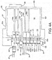
- Each wiring connector WX is selectively connectable and removable from the respective single channel I/O circuit board 55. More particularly, each wiring connector WX comprises wiring connector contacts WC ( FIGS. 4 & 4A ) that selectively mate with the interface contacts IC of an I/O board interface connector IX. The wiring connector WX mechanically engages with a respective one of the I/O board interface connectors IX such that the connector contacts WC operably mate with the interface contacts IC to allow power and I/O data to flow between the single channel I/O circuit board 55 and one or more of the of the field devices/processes 26 via wire terminals T and field lines 24 using the single I/O channel C1 - C8 provided by the I/O circuit board 55.
- FIG. 4A is similar to FIG. 4 but shows a different configuration in which certain components have been removed or separated.
- Each of the wiring connectors WX is selectively releasably connected to said body 52 in alignment and association with one of the plurality of slots S1-S8.
- FIG. 4A it can be seen that the wiring connectors WX6 - WX8 are selectively connectable to the body in respective association and alignment with I/O channel slots S6 - S8 even if the slot is otherwise empty, i.e., even if the I/O channel slots do not include an installed I/O circuit board 55 as is the case in FIG. 4A for slots S6 - S8.
- an I/O circuit board 55 is installed in a slot S1- S8
- a wiring connector WX is received and retained in its respective slot S1 - S8 and engages the body 52 with a snap-fit or other releasable engagement. If an I/O circuit board 55 is fully installed in a slot S1 - S8, as is the case for slots S1,S2, S4,S5 of FIG. 4A , the wiring connector WX will mate with and engage the interface connector IX of the respective I/O circuit board 55 when the wiring connector WX is installed in its slot S1 - S8 such that the respective contacts WC,IC operably mate.
- Each individual wiring connector WX can also be selectively removed from its slot S 1 - S8 with or without removing the corresponding associated I/O circuit board 55 from the same slot S1 - S8 and this can facilitate making wiring connections with the wiring connector WX even before the I/O module 50 is present or installed, i.e., the field lines 24 can be connected to a wiring connector WX in advance of the I/O module 50 being present or installed.
- the above-described features provide an I/O module that is much easier to install, configure, reconfigure, and repair relative to known I/O modules such as the I/O modules 20 described in FIGS. 1 and 2 .
- the ability to physically and electrically separate the wiring connector WX from a respective one of the I/O circuit boards 55 allows the field lines 24 to be configured and connected between the field device/process 26 and to the wiring connector WX in advance, before the I/O module 50 and/or before the single channel I/O circuit board 55 is selected and/or installed or available, which greatly simplifies the installation process.
- the wiring connector WX including the field lines 24 already connected to the terminals T thereof is then operatively installed in the corresponding slot S1-S8 so that the wiring connector contacts WC mechanically and electrically mate with the board interface contacts IC.
- any individual I/O circuit board 55 can be repaired, replaced and/or reconfigured by a reverse process in which the wiring connector WX is separated from its slot S1-S8 so that the wiring connector contacts WC disconnect from the board interface contacts IC without the need for separating the field lines 24 from the wiring connector terminals T.
- the I/O circuit board 55 can then be removed from its slot S1-S8 (see arrow R1) and replaced with the same, repaired circuit board or another I/O circuit board 55 having the same or a different configuration, all without powering-down the I/O module.
- the field lines 24, wiring connectors WX and I/O circuit boards 55 associated with and connected to all other I/O channels C1-C8 of the module 50 are unaffected and need not be disconnected.
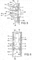
- the modular sub-chassis further comprises ribs R defined in the left and right body side walls 52c,52d, and parallel pairs of the ribs R partially define the slots S1-S8 there between in alignment with the respective I/O board connectors Z (to simplify the drawing, only one pair of ribs R partially defining the slot S1 is shown in FIG. 5 , but each slot S1 - S8 includes similar ribs R defined in both the left and right body side walls 52c,52d).
- the modular sub-chassis SC1 comprises the primary circuit board 54 including the I/O board connectors Z, and further comprises the corresponding slots S1-S8 defined at least partially by the ribs R.
- FIG. 6 is a partial side view of the I/O module of FIG. 3 showing a second embodiment of an I/O channel modular sub-chassis SC2 for insertion and removal of individual I/O channel circuit subsystems/boards 55.
- the primary circuit board 54 is located adjacent the module right side wall 52d (and/or alternatively the left side wall 52c) and is electrically connected to the module connector 28.
- the primary circuit board 54 comprises a plurality of I/O board connectors Z respectively associated with the I/O channels C1-C8 and in respective alignment with the slots S1-S8.
Landscapes
- Engineering & Computer Science (AREA)
- General Engineering & Computer Science (AREA)
- Theoretical Computer Science (AREA)
- Physics & Mathematics (AREA)
- General Physics & Mathematics (AREA)
- Automation & Control Theory (AREA)
- Microelectronics & Electronic Packaging (AREA)
- Computer Hardware Design (AREA)
- Mounting Of Printed Circuit Boards And The Like (AREA)
- Programmable Controllers (AREA)
Abstract
Description
- The present development relates to industrial automation control systems and, more particularly, to an input/output (I/O) module of such a system including a plurality of single channel I/O subsystems installed in a modular sub-chassis such that individual I/O channels can be installed and removed as desired while leaving all other I/O channels of the module unaffected.
-
FIG. 1 shows a first example of an industrial control system CS including anindustrial automation controller 100 and a distributed industrial automation input/output (I/O)system 10 operatively connected to the industrial controller. The I/O system 10 includes anetwork adapter module 12 providing aconnection 14 to anindustrial data network 16. Thedata network 16 may be any one of a number of industrial control or I/O networks including but not limited to ControlNet, DeviceNet, EtherNet/IP, RIO, ASi, PROFIBUS, PROFInet, Foundation Fieldbus or the like as are well known in the art of industrial automation data networks. Theadapter module 12 communicates over thenetwork 16 with theindustrial controller 100 to receive output data from the industrial controller or to provide input data to theindustrial controller 100 to be processed according to a control program executed by a PLC and/or other processor(s) of theindustrial controller 100. Thenetwork 16 can be hard-wired or wireless. - With respect to the I/O system, itself, the
adapter module 12 communicates with a backplane circuit B (often referred to simply as the "backplane") to operably connect theindustrial controller 100 to one or more I/O modules 20 that are operably connected to the backplane B. In the illustrated embodiment, a physical base orchassis 18 is provided to contain theadapter module 12 and to contain the I/O modules 20. At least the I/O modules 20, and optionally also theadapter module 12, are selectively insertable and removable to/from thechassis 18 to provide the modularity required for customization, module repair/replacement, expansion capability, and the like. - The I/
O modules 20 connect via I/O field lines 24 (e.g., electrical cables, fiber optic cables, etc.) with a controlled device orprocess O modules 20 convert digital data received over the backplane B from thecontroller 100 andadapter module 12 into output signals (either digital or analog) in a form suitable for input to an industrial process 26. The I/O modules 20 typically also receive digital or analog signals from an industrial process 26 and convert same to digital data suitable for transmission on the backplane B to theadapter module 12 and, thereafter, to thecontroller 100 for processing. -
FIG. 2 is similar toFIG. 1 but shows an alternative industrial automation control system CS' in which theindustrial controller 100 is also mechanically connected to thechassis 18 and directly operably connected to the backplane B for communication of data to and from the I/O modules 20, in which case theadapter module 12 is eliminated. In such case, theindustrial controller 100 and the I/O modules 20 communicate with each other directly over the backplane circuit B. - In either the example of
FIG. 1 or FIG. 2 , modularity of the I/O modules 20 with respect to thechassis 18 and backplane B is provided through anelectrical module connector 28 on each I/O module 20 which may be mated with any one of a number of correspondingelectrical backplane connectors 30 extending from and operatively connected to the backplane B. Thebackplane connectors 30 are each associated with a respective physical and logical module mounting location or "slot," and thechassis 18 provides mechanical features (not shown) associated with each slot for mechanically releasably securing each I/O module 20 to thechassis 18 in its operative position. - Furthermore, for both of the above-described systems CS,CS' of
FIGS. 1 and 2 , each I/O module 20, itself, includes multiple I/O communications channels O module 20 can be operably connected to communicate with a corresponding multiple number of field devices or processes 26. One deficiency of known systems is that the I/O channels 22 of eachmodule 20 are manufactured with a select type (analog or digital, input or output) that cannot be altered after themodule 20 is manufactured and that cannot be customized for a particular user's requirements. This limitation often requires that an end-user purchasemore modules 20 than desired in order to have the required types of I/O channels for a particular application, even though certain I/O channels (of the type not needed for that particular application) are not being used. Another drawback associated with known systems is that a failure of one of the I/O channels O module 20 requires that the entire I/O module 20 be removed and replaced, even though only one of the channels 22 of the module has failed. This is highly undesirable because replacement of an I/O module 20 for failure of a single channel 22 of the module creates a significant expense for replacement of the complete I/O module. Also, every device or process 26 connected to not only the faulty I/O channel 22 but also the properly functioning I/O channels 22 of themodule 20 must be stopped and disconnected from the I/O module 20 until areplacement module 20 is installed, which typically also requires associated devices and processes 26 being controlled to be stopped until the I/O module 20 with the defective I/O channel 22 is replaced. - In accordance with one aspect of the present development, an industrial automation input/output (I/O) module includes a body defining an internal space including a plurality of slots. A module backplane connector is connected to the body, and a primary backplane interface circuit board is located in the space of the body. The primary backplane interface circuit board is electrically connected to the module backplane connector and includes electronic devices configured to transmit data and power to and from an associated backplane circuit through the module backplane connector. A plurality of individual I/O circuit boards are installed respectively in the plurality of slots of the body. Each of the I/O circuit boards includes electronic devices configured to provide a single-channel I/O circuit for input or output of data with respect to an associated field device. Each of the I/O circuit boards is electrically connected to the primary backplane interface circuit board when installed in a respective one of said slots, and each of the plurality of I/O circuit boards is selectively removable from its respective slot and from the internal space of the body for selective electrical disconnection of said I/O circuit board from the primary backplane interface circuit board.
- In accordance with another aspect of the present development, an industrial automation control system includes an industrial automation controller and a plurality of input/output (I/O) modules operatively connected to the industrial automation controller through an industrial data network. The I/O modules are operatively connected to a chassis comprising a backplane circuit. The I/O modules each include a body defining an internal space including a plurality of slots. A module backplane connector is connected to the body for operative electrical connection with the backplane circuit. A primary backplane interface circuit board is located in the space of the body. The primary backplane interface circuit board is electrically connected to the module backplane connector and includes electronic devices configured to transmit data and power to and from the backplane circuit through the module backplane connector. A plurality of individual single-channel I/O circuit boards are installed respectively in the plurality of slots of the body. Each of the I/O circuit boards includes electronic devices configured to provide a single-channel I/O circuit for input or output of data with respect to an associated field device or process. Each of said single-channel I/O circuit boards is operatively electrically connected to the primary backplane interface circuit board when installed in a respective one of said slots, and each of the plurality of I/O circuit boards is selectively removable from its respective slot and from the internal space of the body for selective electrical disconnection of said I/O circuit board from the primary backplane interface circuit board.
-
-
FIG. 1 shows a first example of a known industrial control system including an industrial automation controller and a distributed industrial automation input/output (I/O) system. -
FIG. 2 shows a second example of a known industrial control system in which the industrial automation controller and input/output (I/O) system are provided in an integral unit; -
FIG. 3 is a front elevation view of an I/O module provided in accordance with the present development and comprising single channel I/O in a modular sub-chassis; -
FIG. 4 is a section view of the I/O module ofFIG. 3 as taken at line 4 - 4 ofFIG. 3 ; -
FIG. 4A is similar toFIG. 4 but shows a different configuration in which certain components have been removed or separated; -
FIG. 5 is a partial side view of the I/O module ofFIG. 3 showing a first embodiment of an I/O channel modular sub-chassis for insertion and removal of individual I/O channel circuit subsystems; -
FIG. 6 is a partial side view of the I/O module ofFIG. 3 showing a second embodiment of an I/O channel modular sub-chassis for insertion and removal of individual I/O channel circuit subsystems. -
FIG. 3 is a front elevation view of an I/O module 50 provided in accordance with the present development and comprising a modular sub-chassis for insertion and removal of individual single I/O channel subsystems or channels C1 - C8.FIG. 4 is a section view of the I/O module ofFIG. 3 as taken at line 4 - 4 ofFIG. 3 . The I/O module 50 is adapted to be physically connected to the base orchassis 18 ofFIG. 1 or FIG. 2 . The I/O module 50 comprises an electricalmodule backplane connector 28 adapted to be operably connected to theelectrical backplane connector 30 of thechassis 18 to operably connect themodule 50 to the backplane B for communication of power and data between themodule 50 andbackplane 18. - In
FIGS. 3 and 4 , it can be seen that themodule 50 comprises a housing orbody 52 including afront wall 52a, arear wall 52b, left andright side walls top wall 52e, and abottom wall 52f. In the illustrated example, the front andrear walls right side walls bottom walls right side walls body 52 thus defines an internal space P for containing a primary backplane interface circuit board 54 (also sometimes referred to as the "primary board" or "motherboard") and a plurality of single channel I/O circuit boards orother subsystems 55a - 55h (generally 55 and each sometimes referred to as an "I/O board" or a "daughterboard") respectively associated with and providing the data input/output functionality for the I/O channels C1 - C8. Thefront wall 52a includes or defines a plurality of slots S1-S8 that are adapted to releasably receive and retain the respective I/O channels C1 - C8 are further described below. The slots S1 - S8 can be physically separate from each other or defined as respective portions of a single open slot. - The
primary board 54 is operably connected to themodule connector 28 so that the components of theprimary board 54 can be selectively operably coupled to the backplane B through a backplane connector 30 (FIGS. 1 & 2 ) with which themodule connector 28 is mated. As described in more detail below with reference toFIGS. 5 and 6 , each of the I/O boards 55 is selectively releasably installed in a respective slot S1 - S8 and operably physically and electrically coupled to theprimary board 54 for communication of power and single channel I/O data between theprimary board 54 and the installed I/O board 55. Theprimary board 54 includes all electronic devices andcircuitry 54e required for communication of power and data to/from the backplane B through themodule connector 28, and the electronic circuitry of theprimary board 54 is thus shared by all of the single channel I/O boards 55 connected to theprimary board 54. Each single channel I/O circuit board 55, on the other hand, includes electronic devices andcircuitry 55e dedicated to a particular I/O function and a particular type of I/O data, e.g., AC digital input, AC digital output, DC digital input, DC digital output, analog input, analog RTD or thermocouple, analog output, Highway Addressable Remote Transducer (HART) input or output modules, or any other specific type of dedicated I/O circuitry associated only with one of the I/O channels C1 - C8. In particular, each I/O circuit board 55 comprises electronic circuitry such as A/D converters, D/A converters, multiplexers, buffers, counters, controllers, serializers, timers, I/O logic, memory, and/or like electronic devices such that the I/O circuit 55e: (i) connects viafield connections 24 with the controlled system(s) 26; (ii) converts digital data received from theindustrial controller 100 vianetwork adapter 12 into analog or digital output signals for input to the controlled devices 26 or other parts of the controlled system; and/or, (iii) receives digital or analog signals from the controlled field devices 26 or elsewhere and converts the received signals to digital data suitable for transmission to theindustrial controller 100 vianetwork adapter 12. - The I/
O circuit board 55 of each I/O channel C1 - C8 further comprises an interface connector IX including electrical interface contacts IC. Each I/O channel C1 - C8 further comprises a respective wiring connector WX1 - WX8 (generally WX) that is releasably connected to the interface connector IX of the respective I/O circuit board 55a - 55h. Each wiring connector WX includes one or more wire terminals T for operative connection of the I/O field lines 24 that are connected to the field devices or processes 26. As shown herein, each wiring connector WX comprises four wire terminals T, but more or fewer wire terminals T can be provided. - Each wiring connector WX is selectively connectable and removable from the respective single channel I/
O circuit board 55. More particularly, each wiring connector WX comprises wiring connector contacts WC (FIGS. 4 &4A ) that selectively mate with the interface contacts IC of an I/O board interface connector IX. The wiring connector WX mechanically engages with a respective one of the I/O board interface connectors IX such that the connector contacts WC operably mate with the interface contacts IC to allow power and I/O data to flow between the single channel I/O circuit board 55 and one or more of the of the field devices/processes 26 via wire terminals T andfield lines 24 using the single I/O channel C1 - C8 provided by the I/O circuit board 55. -
FIG. 4A is similar toFIG. 4 but shows a different configuration in which certain components have been removed or separated. Each of the wiring connectors WX is selectively releasably connected to saidbody 52 in alignment and association with one of the plurality of slots S1-S8. InFIG. 4A , it can be seen that the wiring connectors WX6 - WX8 are selectively connectable to the body in respective association and alignment with I/O channel slots S6 - S8 even if the slot is otherwise empty, i.e., even if the I/O channel slots do not include an installed I/O circuit board 55 as is the case inFIG. 4A for slots S6 - S8. In particular, whether or not an I/O circuit board 55 is installed in a slot S1- S8, a wiring connector WX is received and retained in its respective slot S1 - S8 and engages thebody 52 with a snap-fit or other releasable engagement. If an I/O circuit board 55 is fully installed in a slot S1 - S8, as is the case for slots S1,S2, S4,S5 ofFIG. 4A , the wiring connector WX will mate with and engage the interface connector IX of the respective I/O circuit board 55 when the wiring connector WX is installed in its slot S1 - S8 such that the respective contacts WC,IC operably mate. Each individual wiring connector WX can also be selectively removed from its slot S 1 - S8 with or without removing the corresponding associated I/O circuit board 55 from the same slot S1 - S8 and this can facilitate making wiring connections with the wiring connector WX even before the I/O module 50 is present or installed, i.e., the field lines 24 can be connected to a wiring connector WX in advance of the I/O module 50 being present or installed. - Those of ordinary skill in the art will recognize that the above-described features provide an I/O module that is much easier to install, configure, reconfigure, and repair relative to known I/O modules such as the I/
O modules 20 described inFIGS. 1 and 2 . In particular, the ability to physically and electrically separate the wiring connector WX from a respective one of the I/O circuit boards 55 allows the field lines 24 to be configured and connected between the field device/process 26 and to the wiring connector WX in advance, before the I/O module 50 and/or before the single channel I/O circuit board 55 is selected and/or installed or available, which greatly simplifies the installation process. Once the I/O module is installed and the appropriate single channel I/O circuit board 55 is installed in its intended slot S1-S8, the wiring connector WX including the field lines 24 already connected to the terminals T thereof is then operatively installed in the corresponding slot S1-S8 so that the wiring connector contacts WC mechanically and electrically mate with the board interface contacts IC. Of course, any individual I/O circuit board 55 can be repaired, replaced and/or reconfigured by a reverse process in which the wiring connector WX is separated from its slot S1-S8 so that the wiring connector contacts WC disconnect from the board interface contacts IC without the need for separating the field lines 24 from the wiring connector terminals T. The I/O circuit board 55 can then be removed from its slot S1-S8 (see arrow R1) and replaced with the same, repaired circuit board or another I/O circuit board 55 having the same or a different configuration, all without powering-down the I/O module. In any such repair or reconfiguration process, the field lines 24, wiring connectors WX and I/O circuit boards 55 associated with and connected to all other I/O channels C1-C8 of themodule 50 are unaffected and need not be disconnected. -
FIG. 5 is a partial side view of the I/O module ofFIG. 3 showing a first embodiment of an I/O channel modular sub-chassis SC1 for insertion and removal of the individual I/O channel circuit subsystems orboards 55. In the example ofFIG. 5 , at least part of theprimary circuit board 54 is located adjacent the modulerear wall 52b and electrically connected to themodule connector 28. Theprimary circuit board 54 comprises a plurality of I/O board connectors Z respectively associated with the I/O channels C1-C8 and in respective alignment with the slots S1-S8. In addition to the I/O board connectors Z, the modular sub-chassis further comprises ribs R defined in the left and rightbody side walls FIG. 5 , but each slot S1 - S8 includes similar ribs R defined in both the left and rightbody side walls primary circuit board 54 including the I/O board connectors Z, and further comprises the corresponding slots S1-S8 defined at least partially by the ribs R. When an I/O circuit board 55 is fully inserted into its slot S1-58, the corresponding I/O board connector Z mechanically received and retains the I/O circuit board 55, and power and data contacts 55X of thecircuit board 55 electrically mate with corresponding contacts in the board connector Z for communication of power and data between the I/O board 55 and theprimary board 54 andconnector 28. -
FIG. 6 is a partial side view of the I/O module ofFIG. 3 showing a second embodiment of an I/O channel modular sub-chassis SC2 for insertion and removal of individual I/O channel circuit subsystems/boards 55. In the example ofFIG. 6 , at least part of theprimary circuit board 54 is located adjacent the moduleright side wall 52d (and/or alternatively theleft side wall 52c) and is electrically connected to themodule connector 28. Theprimary circuit board 54 comprises a plurality of I/O board connectors Z respectively associated with the I/O channels C1-C8 and in respective alignment with the slots S1-S8. In addition to the I/O board connectors Z, the modular sub-chassis SC2 further comprises ribs R defined in theside wall 52c opposite the I/O board connectors Z, and parallel pairs of the ribs R partially define the slots S1-S8 there between. As such, the modular sub-chassis SC2 comprises theprimary circuit board 54 including the I/O board connectors Z, and further comprises the corresponding slots S1-S8 defined at least partially by the ribs R. When an I/O circuit board 55 is inserted into its slot S 1-S8, the corresponding I/O board connector Z mechanically received and retains one of the lateral edges of the I/O circuit board 55, and power and data contacts 55X of thecircuit board 55 electrically mate with corresponding contacts in the board connector Z for communication of power and data between the I/O board 55 and theprimary board 54 andconnector 28. - In the preceding specification, various embodiments have been described with reference to the accompanying drawings. It will, however, be evident that various modifications and changes may be made thereto, and additional embodiments may be implemented, without departing from the broader scope of the invention as set forth in the claims that follow. The specification and drawings are accordingly to be regarded in an illustrative rather than restrictive sense.
- The following is a list of further preferred embodiments of the invention:
-
Embodiment 1. An industrial automation input/output (I/O) module comprising:- a body defining an internal space including a plurality of slots;
- a module backplane connector connected to said body;
- a primary backplane interface circuit board located in said space of said body, said primary backplane interface circuit board electrically connected to said module backplane connector and comprising electronic devices configured to transmit data and power to and from an associated backplane circuit through said module backplane connector;
- a plurality of individual I/O circuit boards installed respectively in said plurality of slots of said body, each of said I/O circuit boards comprising electronic devices configured to provide a single-channel I/O circuit for input or output of data with respect to an associated field device, wherein:
- each of said I/O circuit boards is electrically connected to said primary backplane interface circuit board when installed in a respective one of said slots; and,
- each of said plurality of I/O circuit boards is selectively removable from its respective slot and from said internal space of said body for selective electrical disconnection of said I/O circuit board from said primary backplane interface circuit board.
-
Embodiment 2. The industrial automation input/output (I/O) module as set forth inembodiment 1, wherein said body comprises a front wall through which each of said slots opens. -
Embodiment 3. The industrial automation input/output (I/O) module as set forth inembodiment 2, further comprising a plurality of wiring connectors respectively removably engaged with the plurality of I/O circuit boards, each of said wiring connectors comprising at least one wiring terminal adapted to be electrically connected to a field line of an associated I/O field device. -
Embodiment 4. The industrial automation input/output (I/O) module as set forth inembodiment 3, wherein each of said wiring connectors is selectively releasably connected to said body in alignment and association with one of said plurality of slots. -
Embodiment 5. The industrial automation input/output (I/O) module as set forth inembodiment 3, wherein:- each of said I/O circuit boards comprises an interface connector comprising interface contacts;
- each of said wiring connectors is engaged with one of said interface connectors;
- each of said wiring connectors comprises wiring connector contacts; and,
- said wiring connector contacts of each wiring connector are mechanically and electrically engaged with the interface contacts of the interface connector with which said wiring connector is engaged.
- Embodiment 6. The industrial automation input/output (I/O) module as set forth in
embodiment 5, wherein each of said I/O circuit boards further comprises power and data contacts, said I/O module further comprising:- a plurality of I/O board connectors each connected to said primary backplane interface circuit board in respective alignment with said slots and each respectively releasably electrically engaged with said power and data contacts of said plurality of I/O circuit boards.
- Embodiment 7. The industrial automation input/output (I/O) module as set forth in embodiment 6, wherein each of said slots is partially defined by a pair of ribs connected to said body in alignment with one of said I/O board connectors.
-
Embodiment 8. The industrial automation input/output (I/O) module as set forth in embodiment 7, wherein said body further comprises a rear wall located opposite said front wall, and comprise opposite spaced-apart left and right side walls that extend between and connect said front and rear walls, said primary backplane interface circuit board located adjacent said rear wall and said ribs connected to at least one of said left and right side walls. - Embodiment 9. The industrial automation input/output (I/O) module as set forth in embodiment 7, wherein said body further comprises a rear wall located opposite said front wall, and comprise opposite spaced-apart left and right side walls that extend between and connect said front and rear walls, said primary backplane interface circuit board located adjacent one of said left and right side walls, wherein said ribs are connected to the other one of said left and right side walls.
-
Embodiment 10. The industrial automation input/output (I/O) module as set forth inembodiment 5, wherein each of said I/O circuit boards comprises at least one of: an AC digital input circuit, an AC digital output circuit, a DC digital input circuit, a DC digital output circuit, an analog input circuit, an analog RTD circuit; a thermocouple circuit, an analog output circuit, a Highway Addressable Remote Transducer (HART) circuit. - Embodiment 11. An industrial automation control system comprising:
- an industrial automation controller and a plurality of input/output (I/O) modules operatively connected to the industrial automation controller through an industrial data network, wherein said I/O modules are operatively connected to a chassis comprising a backplane circuit and comprise:
- a body defining an internal space including a plurality of slots;
- a module backplane connector connected to said body for operative electrical connection with said backplane circuit;
- a primary backplane interface circuit board located in said space of said body, said primary backplane interface circuit board electrically connected to said module backplane connector and comprising electronic devices configured to transmit data and power to and from the backplane circuit through said module backplane connector;
- a plurality of individual single-channel I/O circuit boards installed respectively in said plurality of slots of said body, each of said I/O circuit boards comprising electronic devices configured to provide a single-channel I/O circuit for input or output of data with respect to an associated field device or process, wherein:
- each of said single-channel I/O circuit boards is operatively electrically connected to said primary backplane interface circuit board when installed in a respective one of said slots; and,
- each of said plurality of I/O circuit boards is selectively removable from its respective slot and from said internal space of said body for selective electrical disconnection of said I/O circuit board from said primary backplane interface circuit board.
- an industrial automation controller and a plurality of input/output (I/O) modules operatively connected to the industrial automation controller through an industrial data network, wherein said I/O modules are operatively connected to a chassis comprising a backplane circuit and comprise:
-
Embodiment 12. The industrial automation control system as set forth in embodiment 11, wherein said body comprises a front wall through which each of said slots opens. - Embodiment 13. The industrial automation control system as set forth in
embodiment 12, further comprising a plurality of wiring connectors respectively removably engaged with the plurality of single-channel I/O circuit boards, each of said wiring connectors comprising at least one wiring terminal adapted to be electrically connected to a field line of an associated I/O field device. -
Embodiment 14. The industrial automation control system as set forth in embodiment 13, wherein each of said wiring connectors is selectively releasably connected to said body in alignment and association with one of said plurality of slots, wherein each of said wiring connectors is connectable to said body independently of said single-channel I/O circuit boards. - Embodiment 15. The industrial automation control system as set forth in embodiment 13, wherein:
- each of said single-channel I/O circuit boards comprises an interface connector comprising interface contacts;
- each of said wiring connectors is engaged with one of said interface connectors;
- each of said wiring connectors comprises wiring connector contacts; and,
- said wiring connector contacts of each wiring connector are mechanically and electrically engaged with the interface contacts of the interface connector with which said wiring connector is engaged.
-
Embodiment 16. The industrial automation control system as set forth in embodiment 15, wherein each of said single-channel I/O circuit boards further comprises power and data contacts, each of said I/O modules further comprising:- a plurality of I/O board connectors each connected to said primary backplane interface circuit board in respective alignment with said slots and each respectively releasably electrically engaged with said power and data contacts of said plurality of I/O circuit boards.
- Embodiment 17. The industrial automation control system as set forth in
embodiment 16, wherein each of said slots is partially defined by a pair of ribs connected to said body in alignment with one of said I/O board connectors. -
Embodiment 18. The industrial automation control system as set forth in embodiment 17, wherein said body further comprises a rear wall located opposite said front wall, and comprise opposite spaced-apart left and right side walls that extend between and connect said front and rear walls, said primary backplane interface circuit board located adjacent said rear wall and said ribs connected to at least one of said left and right side walls. - Embodiment 19. The industrial automation control system as set forth in embodiment 17, wherein said body further comprises a rear wall located opposite said front wall, and comprise opposite spaced-apart left and right side walls that extend between and connect said front and rear walls, said primary backplane interface circuit board located adjacent one of said left and right side walls, wherein said ribs are connected to the other one of said left and right side walls.
-
Embodiment 20. The industrial automation control system as set forth in embodiment 15, wherein each of said I/O circuit boards comprises at least one of: an AC digital input circuit, an AC digital output circuit, a DC digital input circuit, a DC digital output circuit, an analog input circuit, an analog RTD circuit; a thermocouple circuit, an analog output circuit, a Highway Addressable Remote Transducer (HART) circuit.
Claims (12)
- An industrial automation input/output (I/O) module comprising:a body defining an internal space including a plurality of slots;a module backplane connector connected to said body;a primary backplane interface circuit board located in said space of said body, said primary backplane interface circuit board electrically connected to said module backplane connector and comprising electronic devices configured to transmit data and power to and from an associated backplane circuit through said module backplane connector;a plurality of individual I/O circuit boards installed respectively in said plurality of slots of said body, each of said I/O circuit boards comprising electronic devices configured to provide a single-channel I/O circuit for input or output of data with respect to an associated field device, wherein:each of said I/O circuit boards is electrically connected to said primary backplane interface circuit board when installed in a respective one of said slots; and,each of said plurality of I/O circuit boards is selectively removable from its respective slot and from said internal space of said body for selective electrical disconnection of said I/O circuit board from said primary backplane interface circuit board.
- The industrial automation input/output (I/O) module as set forth in claim 1, wherein said body comprises a front wall through which each of said slots opens.
- The industrial automation input/output (I/O) module as set forth in claim 1 or 2, further comprising a plurality of wiring connectors respectively removably engaged with the plurality of I/O circuit boards, each of said wiring connectors comprising at least one wiring terminal adapted to be electrically connected to a field line of an associated I/O field device.
- The industrial automation input/output (I/O) module as set forth in claim 3, wherein each of said wiring connectors is selectively releasably connected to said body in alignment and association with one of said plurality of slots.
- The industrial automation input/output (I/O) module as set forth in claim 3 or 4, wherein:each of said I/O circuit boards comprises an interface connector comprising interface contacts;each of said wiring connectors is engaged with one of said interface connectors;each of said wiring connectors comprises wiring connector contacts; and,said wiring connector contacts of each wiring connector are mechanically and electrically engaged with the interface contacts of the interface connector with which said wiring connector is engaged.
- The industrial automation input/output (I/O) module as set forth in one of claims 1 to 5, wherein each of said I/O circuit boards further comprises power and data contacts, said I/O module further comprising:a plurality of I/O board connectors each connected to said primary backplane interface circuit board in respective alignment with said slots and each respectively releasably electrically engaged with said power and data contacts of said plurality of I/O circuit boards.
- The industrial automation input/output (I/O) module as set forth in claim 6, wherein each of said slots is partially defined by a pair of ribs connected to said body in alignment with one of said I/O board connectors.
- The industrial automation input/output (I/O) module as set forth in claim 7, wherein said body further comprises a rear wall located opposite the body's front wall, and comprise opposite spaced-apart left and right side walls that extend between and connect said front and rear walls, said primary backplane interface circuit board located adjacent said rear wall and said ribs connected to at least one of said left and right side walls.
- The industrial automation input/output (I/O) module as set forth in claim 7, wherein said body further comprises a rear wall located opposite the body's front wall, and comprise opposite spaced-apart left and right side walls that extend between and connect said front and rear walls, said primary backplane interface circuit board located adjacent one of said left and right side walls, wherein said ribs are connected to the other one of said left and right side walls.
- The industrial automation input/output (I/O) module as set forth in one of claims 1 to 9, wherein each of said I/O circuit boards comprises at least one of: an AC digital input circuit, an AC digital output circuit, a DC digital input circuit, a DC digital output circuit, an analog input circuit, an analog RTD circuit; a thermocouple circuit, an analog output circuit, a Highway Addressable Remote Transducer (HART) circuit.
- An industrial automation control system comprising:an industrial automation controller and a plurality of input/output (I/O) modules operatively connected to the industrial automation controller through an industrial data network, wherein said I/O modules are operatively connected to a chassis comprising a backplane circuit and comprise:a body defining an internal space including a plurality of slots;a module backplane connector connected to said body for operative electrical connection with said backplane circuit;a primary backplane interface circuit board located in said space of said body, said primary backplane interface circuit board electrically connected to said module backplane connector and comprising electronic devices configured to transmit data and power to and from the backplane circuit through said module backplane connector;a plurality of individual single-channel I/O circuit boards installed respectively in said plurality of slots of said body, each of said I/O circuit boards comprising electronic devices configured to provide a single-channel I/O circuit for input or output of data with respect to an associated field device or process, wherein:each of said single-channel I/O circuit boards is operatively electrically connected to said primary backplane interface circuit board when installed in a respective one of said slots; and,each of said plurality of I/O circuit boards is selectively removable from its respective slot and from said internal space of said body for selective electrical disconnection of said I/O circuit board from said primary backplane interface circuit board.
- The industrial automation control system as set forth in claim 11, arranged in accordance with any one of claims 1 to 10.
Applications Claiming Priority (1)
| Application Number | Priority Date | Filing Date | Title |
|---|---|---|---|
| US15/298,772 US9861002B1 (en) | 2016-10-20 | 2016-10-20 | Single channel I/O in a modular sub-chassis |
Publications (2)
| Publication Number | Publication Date |
|---|---|
| EP3313159A1 true EP3313159A1 (en) | 2018-04-25 |
| EP3313159B1 EP3313159B1 (en) | 2024-10-30 |
Family
ID=59982302
Family Applications (1)
| Application Number | Title | Priority Date | Filing Date |
|---|---|---|---|
| EP17193472.2A Active EP3313159B1 (en) | 2016-10-20 | 2017-09-27 | Single channel i/o in a modular sub-chassis |
Country Status (3)
| Country | Link |
|---|---|
| US (1) | US9861002B1 (en) |
| EP (1) | EP3313159B1 (en) |
| CN (1) | CN107966922B (en) |
Cited By (1)
| Publication number | Priority date | Publication date | Assignee | Title |
|---|---|---|---|---|
| GB2640473A (en) * | 2024-04-19 | 2025-10-22 | Atlantic Pumps Ltd | Modular control unit |
Families Citing this family (5)
| Publication number | Priority date | Publication date | Assignee | Title |
|---|---|---|---|---|
| US10503668B2 (en) * | 2016-10-18 | 2019-12-10 | Honeywell International Inc. | Intelligent field input/output (I/O) terminal for industrial control and related system and method |
| CN111856981A (en) * | 2019-04-25 | 2020-10-30 | 上海佑显科技有限公司 | IO controller |
| US10838386B1 (en) | 2019-09-26 | 2020-11-17 | Rockwell Automation Technologies, Inc. | Distributed modular I/O device with configurable single-channel I/O submodules |
| US11093428B2 (en) * | 2020-01-03 | 2021-08-17 | Phoenix Contact Development and Manufacturing, Inc. | Convertible I/O signal processor for a process control network |
| CN112616247B (en) * | 2020-12-17 | 2024-09-10 | 上海海得控制系统股份有限公司 | PLC fixed bottom plate and PLC system |
Citations (1)
| Publication number | Priority date | Publication date | Assignee | Title |
|---|---|---|---|---|
| EP0612205A1 (en) * | 1993-02-18 | 1994-08-24 | Yokogawa Electric Corporation | Input-output unit |
Family Cites Families (14)
| Publication number | Priority date | Publication date | Assignee | Title |
|---|---|---|---|---|
| JP3379075B2 (en) * | 1994-07-11 | 2003-02-17 | インターナショナル・ビジネス・マシーンズ・コーポレーション | Computer with modular removable card cage |
| US6742068B2 (en) * | 1997-06-30 | 2004-05-25 | Emc Corporation | Data server with hot replaceable processing unit modules |
| US5971804A (en) * | 1997-06-30 | 1999-10-26 | Emc Corporation | Backplane having strip transmission line ethernet bus |
| US6241530B1 (en) * | 1997-12-17 | 2001-06-05 | Honeywell Inc. | Backplane assembly for printed circuit boards |
| US6419499B1 (en) * | 2000-08-01 | 2002-07-16 | Alcatel Canada Inc. | Apparatus for electronically interconnecting electronic circuit substrates |
| US20070245165A1 (en) * | 2000-09-27 | 2007-10-18 | Amphus, Inc. | System and method for activity or event based dynamic energy conserving server reconfiguration |
| US6646868B2 (en) * | 2001-06-04 | 2003-11-11 | Sun Microsystems, Inc. | Computer bus rack having an increased density of card slots |
| US7525809B2 (en) * | 2003-09-30 | 2009-04-28 | Rockwell Automation Technologies, Inc. | Isolated control and network wireway for motor control center |
| US7581053B2 (en) | 2003-11-17 | 2009-08-25 | Rockwell Automation Technologies, Inc. | Distributed modular input/output system with wireless backplane extender |
| US7412548B2 (en) * | 2004-03-04 | 2008-08-12 | Rockwell Automation Technologies, Inc. | Intelligent self-determining I/O device |
| US7460375B2 (en) * | 2004-05-07 | 2008-12-02 | Rackable Systems, Inc. | Interface assembly |
| US9411769B2 (en) | 2006-09-19 | 2016-08-09 | Fisher-Rosemount Systems, Inc. | Apparatus and methods to communicatively couple field devices to controllers in a process control system |
| SG192299A1 (en) * | 2012-01-12 | 2013-08-30 | Rockwell Automation Asia Pacific Business Ctr Pte Ltd | System and method for coupling an automation controller and scaleable module |
| US20150092788A1 (en) * | 2012-04-26 | 2015-04-02 | Michael J. Kennedy | Input-output module |
-
2016
- 2016-10-20 US US15/298,772 patent/US9861002B1/en active Active
-
2017
- 2017-09-27 EP EP17193472.2A patent/EP3313159B1/en active Active
- 2017-09-29 CN CN201710909450.6A patent/CN107966922B/en active Active
Patent Citations (1)
| Publication number | Priority date | Publication date | Assignee | Title |
|---|---|---|---|---|
| EP0612205A1 (en) * | 1993-02-18 | 1994-08-24 | Yokogawa Electric Corporation | Input-output unit |
Cited By (1)
| Publication number | Priority date | Publication date | Assignee | Title |
|---|---|---|---|---|
| GB2640473A (en) * | 2024-04-19 | 2025-10-22 | Atlantic Pumps Ltd | Modular control unit |
Also Published As
| Publication number | Publication date |
|---|---|
| EP3313159B1 (en) | 2024-10-30 |
| CN107966922A (en) | 2018-04-27 |
| CN107966922B (en) | 2020-05-29 |
| US9861002B1 (en) | 2018-01-02 |
Similar Documents
| Publication | Publication Date | Title |
|---|---|---|
| EP3313159B1 (en) | Single channel i/o in a modular sub-chassis | |
| EP3715976B1 (en) | Modular backplane for an industrial controller | |
| EP1571510B1 (en) | Intelligent self-determining I/O device | |
| CN101606110B (en) | Control and/or data transmission module | |
| EP3798769B1 (en) | Distributed modular i/o device with configurable single-channel i/o submodules | |
| US8339804B2 (en) | Programmable routing module | |
| US9089067B2 (en) | Modular automation system | |
| EP3798770A1 (en) | Removable terminal block assembly that permits an i/o base to operate in simplex mode or duplex mode | |
| EP3521954A1 (en) | A flexible expandable automation device with hot-swappable i/o-units | |
| EP3312687B1 (en) | On machine input/output (i/o) system with modular connections | |
| CN113261396A (en) | Basic module and functional module for a switchgear cabinet system and switchgear cabinet system | |
| EP2899640B1 (en) | Servo drive device | |
| US10528510B2 (en) | Module for a logic controller | |
| CN105745584A (en) | Automation system | |
| CN103797758A (en) | Communication interface module for automation system | |
| CN110663226B (en) | data bus user equipment | |
| EP4284130A1 (en) | An inlay element, a module termination unit, an input/output device, a modular process control system and a method for assembling an input/output device | |
| CN115316050B (en) | Backplane module for electrically connecting a plurality of functional modules and modularly constructed communication system | |
| RU2749103C1 (en) | Industrial programmable controller |
Legal Events
| Date | Code | Title | Description |
|---|---|---|---|
| PUAI | Public reference made under article 153(3) epc to a published international application that has entered the european phase |
Free format text: ORIGINAL CODE: 0009012 |
|
| STAA | Information on the status of an ep patent application or granted ep patent |
Free format text: STATUS: THE APPLICATION HAS BEEN PUBLISHED |
|
| AK | Designated contracting states |
Kind code of ref document: A1 Designated state(s): AL AT BE BG CH CY CZ DE DK EE ES FI FR GB GR HR HU IE IS IT LI LT LU LV MC MK MT NL NO PL PT RO RS SE SI SK SM TR |
|
| AX | Request for extension of the european patent |
Extension state: BA ME |
|
| STAA | Information on the status of an ep patent application or granted ep patent |
Free format text: STATUS: REQUEST FOR EXAMINATION WAS MADE |
|
| 17P | Request for examination filed |
Effective date: 20181023 |
|
| RBV | Designated contracting states (corrected) |
Designated state(s): AL AT BE BG CH CY CZ DE DK EE ES FI FR GB GR HR HU IE IS IT LI LT LU LV MC MK MT NL NO PL PT RO RS SE SI SK SM TR |
|
| STAA | Information on the status of an ep patent application or granted ep patent |
Free format text: STATUS: EXAMINATION IS IN PROGRESS |
|
| 17Q | First examination report despatched |
Effective date: 20200519 |
|
| GRAP | Despatch of communication of intention to grant a patent |
Free format text: ORIGINAL CODE: EPIDOSNIGR1 |
|
| STAA | Information on the status of an ep patent application or granted ep patent |
Free format text: STATUS: GRANT OF PATENT IS INTENDED |
|
| GRAJ | Information related to disapproval of communication of intention to grant by the applicant or resumption of examination proceedings by the epo deleted |
Free format text: ORIGINAL CODE: EPIDOSDIGR1 |
|
| STAA | Information on the status of an ep patent application or granted ep patent |
Free format text: STATUS: EXAMINATION IS IN PROGRESS |
|
| INTG | Intention to grant announced |
Effective date: 20240229 |
|
| GRAP | Despatch of communication of intention to grant a patent |
Free format text: ORIGINAL CODE: EPIDOSNIGR1 |
|
| STAA | Information on the status of an ep patent application or granted ep patent |
Free format text: STATUS: GRANT OF PATENT IS INTENDED |
|
| INTC | Intention to grant announced (deleted) | ||
| INTG | Intention to grant announced |
Effective date: 20240412 |
|
| GRAS | Grant fee paid |
Free format text: ORIGINAL CODE: EPIDOSNIGR3 |
|
| GRAA | (expected) grant |
Free format text: ORIGINAL CODE: 0009210 |
|
| STAA | Information on the status of an ep patent application or granted ep patent |
Free format text: STATUS: THE PATENT HAS BEEN GRANTED |
|
| AK | Designated contracting states |
Kind code of ref document: B1 Designated state(s): AL AT BE BG CH CY CZ DE DK EE ES FI FR GB GR HR HU IE IS IT LI LT LU LV MC MK MT NL NO PL PT RO RS SE SI SK SM TR |
|
| REG | Reference to a national code |
Ref country code: GB Ref legal event code: FG4D |
|
| REG | Reference to a national code |
Ref country code: CH Ref legal event code: EP |
|
| REG | Reference to a national code |
Ref country code: DE Ref legal event code: R096 Ref document number: 602017085752 Country of ref document: DE |
|
| REG | Reference to a national code |
Ref country code: IE Ref legal event code: FG4D |
|
| REG | Reference to a national code |
Ref country code: LT Ref legal event code: MG9D |
|
| REG | Reference to a national code |
Ref country code: NL Ref legal event code: MP Effective date: 20241030 |
|
| PG25 | Lapsed in a contracting state [announced via postgrant information from national office to epo] |
Ref country code: HR Free format text: LAPSE BECAUSE OF FAILURE TO SUBMIT A TRANSLATION OF THE DESCRIPTION OR TO PAY THE FEE WITHIN THE PRESCRIBED TIME-LIMIT Effective date: 20241030 Ref country code: PT Free format text: LAPSE BECAUSE OF FAILURE TO SUBMIT A TRANSLATION OF THE DESCRIPTION OR TO PAY THE FEE WITHIN THE PRESCRIBED TIME-LIMIT Effective date: 20250228 Ref country code: IS Free format text: LAPSE BECAUSE OF FAILURE TO SUBMIT A TRANSLATION OF THE DESCRIPTION OR TO PAY THE FEE WITHIN THE PRESCRIBED TIME-LIMIT Effective date: 20250228 |
|
| PG25 | Lapsed in a contracting state [announced via postgrant information from national office to epo] |
Ref country code: NL Free format text: LAPSE BECAUSE OF FAILURE TO SUBMIT A TRANSLATION OF THE DESCRIPTION OR TO PAY THE FEE WITHIN THE PRESCRIBED TIME-LIMIT Effective date: 20241030 Ref country code: FI Free format text: LAPSE BECAUSE OF FAILURE TO SUBMIT A TRANSLATION OF THE DESCRIPTION OR TO PAY THE FEE WITHIN THE PRESCRIBED TIME-LIMIT Effective date: 20241030 |
|
| REG | Reference to a national code |
Ref country code: AT Ref legal event code: MK05 Ref document number: 1738229 Country of ref document: AT Kind code of ref document: T Effective date: 20241030 |
|
| PG25 | Lapsed in a contracting state [announced via postgrant information from national office to epo] |
Ref country code: BG Free format text: LAPSE BECAUSE OF FAILURE TO SUBMIT A TRANSLATION OF THE DESCRIPTION OR TO PAY THE FEE WITHIN THE PRESCRIBED TIME-LIMIT Effective date: 20241030 |
|
| PG25 | Lapsed in a contracting state [announced via postgrant information from national office to epo] |
Ref country code: ES Free format text: LAPSE BECAUSE OF FAILURE TO SUBMIT A TRANSLATION OF THE DESCRIPTION OR TO PAY THE FEE WITHIN THE PRESCRIBED TIME-LIMIT Effective date: 20241030 |
|
| PG25 | Lapsed in a contracting state [announced via postgrant information from national office to epo] |
Ref country code: NO Free format text: LAPSE BECAUSE OF FAILURE TO SUBMIT A TRANSLATION OF THE DESCRIPTION OR TO PAY THE FEE WITHIN THE PRESCRIBED TIME-LIMIT Effective date: 20250130 |
|
| PG25 | Lapsed in a contracting state [announced via postgrant information from national office to epo] |
Ref country code: LV Free format text: LAPSE BECAUSE OF FAILURE TO SUBMIT A TRANSLATION OF THE DESCRIPTION OR TO PAY THE FEE WITHIN THE PRESCRIBED TIME-LIMIT Effective date: 20241030 Ref country code: GR Free format text: LAPSE BECAUSE OF FAILURE TO SUBMIT A TRANSLATION OF THE DESCRIPTION OR TO PAY THE FEE WITHIN THE PRESCRIBED TIME-LIMIT Effective date: 20250131 Ref country code: AT Free format text: LAPSE BECAUSE OF FAILURE TO SUBMIT A TRANSLATION OF THE DESCRIPTION OR TO PAY THE FEE WITHIN THE PRESCRIBED TIME-LIMIT Effective date: 20241030 |
|
| PG25 | Lapsed in a contracting state [announced via postgrant information from national office to epo] |
Ref country code: PL Free format text: LAPSE BECAUSE OF FAILURE TO SUBMIT A TRANSLATION OF THE DESCRIPTION OR TO PAY THE FEE WITHIN THE PRESCRIBED TIME-LIMIT Effective date: 20241030 |
|
| PG25 | Lapsed in a contracting state [announced via postgrant information from national office to epo] |
Ref country code: RS Free format text: LAPSE BECAUSE OF FAILURE TO SUBMIT A TRANSLATION OF THE DESCRIPTION OR TO PAY THE FEE WITHIN THE PRESCRIBED TIME-LIMIT Effective date: 20250130 |
|
| PG25 | Lapsed in a contracting state [announced via postgrant information from national office to epo] |
Ref country code: SM Free format text: LAPSE BECAUSE OF FAILURE TO SUBMIT A TRANSLATION OF THE DESCRIPTION OR TO PAY THE FEE WITHIN THE PRESCRIBED TIME-LIMIT Effective date: 20241030 |
|
| PG25 | Lapsed in a contracting state [announced via postgrant information from national office to epo] |
Ref country code: DK Free format text: LAPSE BECAUSE OF FAILURE TO SUBMIT A TRANSLATION OF THE DESCRIPTION OR TO PAY THE FEE WITHIN THE PRESCRIBED TIME-LIMIT Effective date: 20241030 |
|
| PG25 | Lapsed in a contracting state [announced via postgrant information from national office to epo] |
Ref country code: EE Free format text: LAPSE BECAUSE OF FAILURE TO SUBMIT A TRANSLATION OF THE DESCRIPTION OR TO PAY THE FEE WITHIN THE PRESCRIBED TIME-LIMIT Effective date: 20241030 |
|
| PG25 | Lapsed in a contracting state [announced via postgrant information from national office to epo] |
Ref country code: RO Free format text: LAPSE BECAUSE OF FAILURE TO SUBMIT A TRANSLATION OF THE DESCRIPTION OR TO PAY THE FEE WITHIN THE PRESCRIBED TIME-LIMIT Effective date: 20241030 |
|
| PG25 | Lapsed in a contracting state [announced via postgrant information from national office to epo] |
Ref country code: SK Free format text: LAPSE BECAUSE OF FAILURE TO SUBMIT A TRANSLATION OF THE DESCRIPTION OR TO PAY THE FEE WITHIN THE PRESCRIBED TIME-LIMIT Effective date: 20241030 |
|
| PG25 | Lapsed in a contracting state [announced via postgrant information from national office to epo] |
Ref country code: CZ Free format text: LAPSE BECAUSE OF FAILURE TO SUBMIT A TRANSLATION OF THE DESCRIPTION OR TO PAY THE FEE WITHIN THE PRESCRIBED TIME-LIMIT Effective date: 20241030 |
|
| PG25 | Lapsed in a contracting state [announced via postgrant information from national office to epo] |
Ref country code: IT Free format text: LAPSE BECAUSE OF FAILURE TO SUBMIT A TRANSLATION OF THE DESCRIPTION OR TO PAY THE FEE WITHIN THE PRESCRIBED TIME-LIMIT Effective date: 20241030 |
|
| REG | Reference to a national code |
Ref country code: DE Ref legal event code: R097 Ref document number: 602017085752 Country of ref document: DE |
|
| PLBE | No opposition filed within time limit |
Free format text: ORIGINAL CODE: 0009261 |
|
| STAA | Information on the status of an ep patent application or granted ep patent |
Free format text: STATUS: NO OPPOSITION FILED WITHIN TIME LIMIT |
|
| PG25 | Lapsed in a contracting state [announced via postgrant information from national office to epo] |
Ref country code: SE Free format text: LAPSE BECAUSE OF FAILURE TO SUBMIT A TRANSLATION OF THE DESCRIPTION OR TO PAY THE FEE WITHIN THE PRESCRIBED TIME-LIMIT Effective date: 20241030 |
|
| 26N | No opposition filed |
Effective date: 20250731 |
|
| PGFP | Annual fee paid to national office [announced via postgrant information from national office to epo] |
Ref country code: DE Payment date: 20250820 Year of fee payment: 9 |
|
| PGFP | Annual fee paid to national office [announced via postgrant information from national office to epo] |
Ref country code: GB Payment date: 20250822 Year of fee payment: 9 |
|
| PGFP | Annual fee paid to national office [announced via postgrant information from national office to epo] |
Ref country code: FR Payment date: 20250820 Year of fee payment: 9 |
|
| REG | Reference to a national code |
Ref country code: CH Ref legal event code: H13 Free format text: ST27 STATUS EVENT CODE: U-0-0-H10-H13 (AS PROVIDED BY THE NATIONAL OFFICE) Effective date: 20260425 |