EP3313121A1 - Terminal device, communication method, and integrated circuit - Google Patents
Terminal device, communication method, and integrated circuit Download PDFInfo
- Publication number
- EP3313121A1 EP3313121A1 EP16811635.8A EP16811635A EP3313121A1 EP 3313121 A1 EP3313121 A1 EP 3313121A1 EP 16811635 A EP16811635 A EP 16811635A EP 3313121 A1 EP3313121 A1 EP 3313121A1
- Authority
- EP
- European Patent Office
- Prior art keywords
- subframe
- terminal device
- pdcch
- downlink
- pucch
- Prior art date
- Legal status (The legal status is an assumption and is not a legal conclusion. Google has not performed a legal analysis and makes no representation as to the accuracy of the status listed.)
- Granted
Links
- 238000000034 method Methods 0.000 title claims description 45
- 238000004891 communication Methods 0.000 title claims description 20
- 238000012544 monitoring process Methods 0.000 claims abstract description 17
- 238000012545 processing Methods 0.000 claims description 78
- 230000005540 biological transmission Effects 0.000 claims description 60
- 238000010586 diagram Methods 0.000 description 24
- 230000008569 process Effects 0.000 description 17
- 230000011664 signaling Effects 0.000 description 15
- 230000006870 function Effects 0.000 description 9
- 238000005259 measurement Methods 0.000 description 6
- 230000002776 aggregation Effects 0.000 description 5
- 238000004220 aggregation Methods 0.000 description 5
- 230000000737 periodic effect Effects 0.000 description 5
- 230000004044 response Effects 0.000 description 5
- 125000004122 cyclic group Chemical group 0.000 description 4
- 230000000694 effects Effects 0.000 description 4
- 238000005516 engineering process Methods 0.000 description 3
- 101001018494 Homo sapiens Pro-MCH Proteins 0.000 description 2
- 108700026140 MAC combination Proteins 0.000 description 2
- 102100033721 Pro-MCH Human genes 0.000 description 2
- 239000000872 buffer Substances 0.000 description 2
- 230000001413 cellular effect Effects 0.000 description 2
- 238000013461 design Methods 0.000 description 2
- 230000010354 integration Effects 0.000 description 2
- NRNCYVBFPDDJNE-UHFFFAOYSA-N pemoline Chemical compound O1C(N)=NC(=O)C1C1=CC=CC=C1 NRNCYVBFPDDJNE-UHFFFAOYSA-N 0.000 description 2
- 230000002085 persistent effect Effects 0.000 description 2
- 230000001360 synchronised effect Effects 0.000 description 2
- 238000004378 air conditioning Methods 0.000 description 1
- 230000010267 cellular communication Effects 0.000 description 1
- 230000008859 change Effects 0.000 description 1
- 238000004140 cleaning Methods 0.000 description 1
- 238000001514 detection method Methods 0.000 description 1
- 239000000284 extract Substances 0.000 description 1
- 230000008571 general function Effects 0.000 description 1
- 230000007774 longterm Effects 0.000 description 1
- 238000013507 mapping Methods 0.000 description 1
- 230000000873 masking effect Effects 0.000 description 1
- 238000010295 mobile communication Methods 0.000 description 1
- 238000012986 modification Methods 0.000 description 1
- 230000004048 modification Effects 0.000 description 1
- 230000002093 peripheral effect Effects 0.000 description 1
- 238000004886 process control Methods 0.000 description 1
- 239000004065 semiconductor Substances 0.000 description 1
- 238000005406 washing Methods 0.000 description 1
Images


Classifications
-
- H—ELECTRICITY
- H04—ELECTRIC COMMUNICATION TECHNIQUE
- H04L—TRANSMISSION OF DIGITAL INFORMATION, e.g. TELEGRAPHIC COMMUNICATION
- H04L1/00—Arrangements for detecting or preventing errors in the information received
- H04L1/12—Arrangements for detecting or preventing errors in the information received by using return channel
- H04L1/16—Arrangements for detecting or preventing errors in the information received by using return channel in which the return channel carries supervisory signals, e.g. repetition request signals
- H04L1/18—Automatic repetition systems, e.g. Van Duuren systems
- H04L1/1867—Arrangements specially adapted for the transmitter end
- H04L1/188—Time-out mechanisms
-
- H—ELECTRICITY
- H04—ELECTRIC COMMUNICATION TECHNIQUE
- H04W—WIRELESS COMMUNICATION NETWORKS
- H04W24/00—Supervisory, monitoring or testing arrangements
- H04W24/08—Testing, supervising or monitoring using real traffic
-
- H—ELECTRICITY
- H04—ELECTRIC COMMUNICATION TECHNIQUE
- H04J—MULTIPLEX COMMUNICATION
- H04J11/00—Orthogonal multiplex systems, e.g. using WALSH codes
-
- H—ELECTRICITY
- H04—ELECTRIC COMMUNICATION TECHNIQUE
- H04L—TRANSMISSION OF DIGITAL INFORMATION, e.g. TELEGRAPHIC COMMUNICATION
- H04L1/00—Arrangements for detecting or preventing errors in the information received
- H04L1/08—Arrangements for detecting or preventing errors in the information received by repeating transmission, e.g. Verdan system
-
- H—ELECTRICITY
- H04—ELECTRIC COMMUNICATION TECHNIQUE
- H04L—TRANSMISSION OF DIGITAL INFORMATION, e.g. TELEGRAPHIC COMMUNICATION
- H04L1/00—Arrangements for detecting or preventing errors in the information received
- H04L1/12—Arrangements for detecting or preventing errors in the information received by using return channel
- H04L1/16—Arrangements for detecting or preventing errors in the information received by using return channel in which the return channel carries supervisory signals, e.g. repetition request signals
- H04L1/1607—Details of the supervisory signal
- H04L1/1671—Details of the supervisory signal the supervisory signal being transmitted together with control information
-
- H—ELECTRICITY
- H04—ELECTRIC COMMUNICATION TECHNIQUE
- H04L—TRANSMISSION OF DIGITAL INFORMATION, e.g. TELEGRAPHIC COMMUNICATION
- H04L27/00—Modulated-carrier systems
-
- H—ELECTRICITY
- H04—ELECTRIC COMMUNICATION TECHNIQUE
- H04L—TRANSMISSION OF DIGITAL INFORMATION, e.g. TELEGRAPHIC COMMUNICATION
- H04L5/00—Arrangements affording multiple use of the transmission path
- H04L5/003—Arrangements for allocating sub-channels of the transmission path
- H04L5/0053—Allocation of signalling, i.e. of overhead other than pilot signals
- H04L5/0055—Physical resource allocation for ACK/NACK
-
- H—ELECTRICITY
- H04—ELECTRIC COMMUNICATION TECHNIQUE
- H04L—TRANSMISSION OF DIGITAL INFORMATION, e.g. TELEGRAPHIC COMMUNICATION
- H04L5/00—Arrangements affording multiple use of the transmission path
- H04L5/003—Arrangements for allocating sub-channels of the transmission path
- H04L5/0053—Allocation of signalling, i.e. of overhead other than pilot signals
- H04L5/0057—Physical resource allocation for CQI
-
- H—ELECTRICITY
- H04—ELECTRIC COMMUNICATION TECHNIQUE
- H04L—TRANSMISSION OF DIGITAL INFORMATION, e.g. TELEGRAPHIC COMMUNICATION
- H04L5/00—Arrangements affording multiple use of the transmission path
- H04L5/0091—Signalling for the administration of the divided path, e.g. signalling of configuration information
- H04L5/0094—Indication of how sub-channels of the path are allocated
-
- H—ELECTRICITY
- H04—ELECTRIC COMMUNICATION TECHNIQUE
- H04W—WIRELESS COMMUNICATION NETWORKS
- H04W24/00—Supervisory, monitoring or testing arrangements
- H04W24/10—Scheduling measurement reports ; Arrangements for measurement reports
-
- H—ELECTRICITY
- H04—ELECTRIC COMMUNICATION TECHNIQUE
- H04W—WIRELESS COMMUNICATION NETWORKS
- H04W52/00—Power management, e.g. Transmission Power Control [TPC] or power classes
- H04W52/02—Power saving arrangements
-
- H—ELECTRICITY
- H04—ELECTRIC COMMUNICATION TECHNIQUE
- H04W—WIRELESS COMMUNICATION NETWORKS
- H04W72/00—Local resource management
- H04W72/04—Wireless resource allocation
-
- H—ELECTRICITY
- H04—ELECTRIC COMMUNICATION TECHNIQUE
- H04W—WIRELESS COMMUNICATION NETWORKS
- H04W76/00—Connection management
- H04W76/20—Manipulation of established connections
- H04W76/28—Discontinuous transmission [DTX]; Discontinuous reception [DRX]
-
- H—ELECTRICITY
- H04—ELECTRIC COMMUNICATION TECHNIQUE
- H04L—TRANSMISSION OF DIGITAL INFORMATION, e.g. TELEGRAPHIC COMMUNICATION
- H04L1/00—Arrangements for detecting or preventing errors in the information received
- H04L1/12—Arrangements for detecting or preventing errors in the information received by using return channel
- H04L1/16—Arrangements for detecting or preventing errors in the information received by using return channel in which the return channel carries supervisory signals, e.g. repetition request signals
- H04L1/18—Automatic repetition systems, e.g. Van Duuren systems
- H04L1/1812—Hybrid protocols; Hybrid automatic repeat request [HARQ]
-
- H—ELECTRICITY
- H04—ELECTRIC COMMUNICATION TECHNIQUE
- H04W—WIRELESS COMMUNICATION NETWORKS
- H04W52/00—Power management, e.g. Transmission Power Control [TPC] or power classes
- H04W52/02—Power saving arrangements
- H04W52/0209—Power saving arrangements in terminal devices
- H04W52/0212—Power saving arrangements in terminal devices managed by the network, e.g. network or access point is leader and terminal is follower
- H04W52/0216—Power saving arrangements in terminal devices managed by the network, e.g. network or access point is leader and terminal is follower using a pre-established activity schedule, e.g. traffic indication frame
-
- Y—GENERAL TAGGING OF NEW TECHNOLOGICAL DEVELOPMENTS; GENERAL TAGGING OF CROSS-SECTIONAL TECHNOLOGIES SPANNING OVER SEVERAL SECTIONS OF THE IPC; TECHNICAL SUBJECTS COVERED BY FORMER USPC CROSS-REFERENCE ART COLLECTIONS [XRACs] AND DIGESTS
- Y02—TECHNOLOGIES OR APPLICATIONS FOR MITIGATION OR ADAPTATION AGAINST CLIMATE CHANGE
- Y02D—CLIMATE CHANGE MITIGATION TECHNOLOGIES IN INFORMATION AND COMMUNICATION TECHNOLOGIES [ICT], I.E. INFORMATION AND COMMUNICATION TECHNOLOGIES AIMING AT THE REDUCTION OF THEIR OWN ENERGY USE
- Y02D30/00—Reducing energy consumption in communication networks
- Y02D30/70—Reducing energy consumption in communication networks in wireless communication networks
Definitions
- the present invention relates to a terminal device, a communication method, and an integrated circuit.
- LTE Long Term Evolution
- EUTRA Evolved Universal Terrestrial Radio Access
- EUTRAN Evolved Universal Terrestrial Radio Access Network
- LTE Long Term Evolution
- eNodeB evolved NodeB
- UE User Equipment
- LTE is a cellular communication system in which an area is divided into multiple cells to form a cellular pattern, each of the cells being served by a base station device.
- a single base station device may manage multiple cells.
- LTE supports Time Division Duplex (TDD).
- TDD Time Division Duplex
- uplink signals and downlink signals are time-division multiplexed.
- LTE supports Frequency Division Duplex (FDD).
- DCI Downlink Control Information
- PDCCH Physical Downlink Control CHannel
- EPDCCH Enhanced Physical Downlink Control CHannel
- PDSCH Physical Downlink Shared CHannel
- a technique for transmitting a Machine type communication Physical Downlink Control CHannel (MPDCCH) in multiple subframes has been studied in the 3GPP to improve a downlink cell coverage (NPL 1).
- a technique for transmitting a Physical Uplink Control CHannel (PUCCH) in multiple subframes has been studied in the 3GPP to improve an uplink cell coverage (NPL 2).
- a terminal device is capable of efficiently communicating with a base station device on a physical channel included in multiple subframes, an integrated circuit mounted on the terminal device, and a communication method used by the terminal device.
- a terminal device and a base station device are capable of efficiently communicating on physical channels included in multiple subframes.
- FIG. 1 is a conceptual diagram of a radio communication system in the present embodiment.
- the radio communication system includes terminal devices 1A to 1C and a base station device 3.
- terminal devices 1 A to 1C are each referred to as a terminal device 1.
- the present embodiment may be applied to an RRC_CONNECTED state, or only to the terminal device 1 in an RRC_CONNECTED mode.
- the present embodiment may be applied to an RRC_IDLE state or only to the terminal device 1 in the RRC_IDLE state.
- the present embodiment may be applied to both the RRC_CONNECTED state or the terminal device 1 in the RRC_CONNECTED mode, and the RRC_IDLE state or the terminal device 1 in the RRC_IDLE state.
- one serving cell is configured for the terminal device 1.
- the one serving cell may be a primary cell.
- the one serving cell may be a cell on which the terminal device 1 is camping.
- the primary cell is a cell in which an initial connection establishment procedure has been performed, a cell in which a connection re-establishment procedure has started, or a cell indicated as a primary cell in a handover procedure.
- a carrier corresponding to the serving cell is referred to as a downlink component carrier.
- a carrier corresponding to the serving cell is referred to as an uplink component carrier.
- the downlink component carrier and the uplink component carrier are collectively referred to as a component carrier.
- the uplink component carrier and the downlink component carrier correspond to different carrier frequencies.
- the uplink component carrier and the downlink component carrier correspond to the same carrier frequencies.
- the HARQ entity In the downlink, one independent HARQ entity exists for each serving cell (downlink component carrier).
- the HARQ entity manages multiple HARQ processes in parallel.
- Each of the HARQ processes instructs a physical layer to receive data based on a received downlink assignment (downlink control information).
- At least one transport block is generated for each of one or more Transmission Time Intervals (TTIs) for each serving cell.
- TTIs Transmission Time Intervals
- the transport block and HARQ retransmission of the transport block are mapped to one serving cell.
- a TTI serves as a subframe.
- the transport block in the downlink is MAC layer data transmitted on the DownLink Shared CHannel (DL-SCH).
- transport block In the present embodiment, in the uplink, "transport block”, “MAC Protocol Data Unit (PDU)”, “MAC layer data”, “DL-SCH”, “DL-SCH data”, and “downlink data” are assumed to mean the same thing.
- PDU Protocol Data Unit
- One physical channel is mapped to one or more subframes.
- "one physical channel included in multiple subframes”, “one physical channel mapped to multiple subframes”, “one physical channel including resources of multiple subframes”, and “one physical channel repeatedly transmitted over multiple subframes” are assumed to mean the same thing.
- uplink physical channels are used.
- the uplink physical channels are used to transmit information output from a higher layer.
- the PUCCH is used to transmit Uplink Control Information (UCI).
- the uplink control information includes: downlink Channel State Information (CSI); a Scheduling Request (SR) to be used to request a PUSCH (UpLink-Shared CHannel (UL-SCH)) resource for initial transmission; and a Hybrid Automatic Repeat reQuest ACKnowledgement (HARQ-ACK) for downlink data (a transport block, a medium access control protocol data unit (MAC PDU), a DownLink-Shared CHannel (DL-SCH), or a Physical Downlink Shared CHannel (PDSCH)).
- the HARQ-ACK indicates an ACKnowledgement (ACK) or a Negative-ACKnowledgement (NACK).
- the HARQ-ACK is also referred to as ACK/NACK, HARQ feedback, HARQ acknowledge, or HARQ control information.
- the scheduling request includes a positive scheduling request or a negative scheduling request.
- the positive scheduling request indicates requesting of a UL-SCH resource for initial transmission.
- the negative scheduling request indicates not requesting of any UL-SCH resource for initial transmission.
- the PUSCH is used to transmit uplink data (UpLink-Shared CHannel (UL-SCH)). Furthermore, the PUSCH may be used to transmit the HARQ-ACK and/or channel state information along with the uplink data. Furthermore, the PUSCH may be used to transmit only the channel state information. Furthermore, the PUSCH may be used to transmit only the HARQ-ACK and the channel state information.
- uplink data UpLink-Shared CHannel (UL-SCH)
- UL-SCH UpLink-Shared CHannel
- the PUSCH may be used to transmit the HARQ-ACK and/or channel state information along with the uplink data. Furthermore, the PUSCH may be used to transmit only the channel state information.
- the base station device 3 and the terminal device 1 exchange signals in (transmit and receive a signal to and from) higher layers.
- the base station device 3 and the terminal device 1 may transmit and receive RRC signaling in a Radio Resource Control (RRC) layer.
- the base station device 3 and the terminal device 1 may transmit and receive a Medium Access Control (MAC) CE in a MAC layer.
- RRC Radio Resource Control
- MAC Medium Access Control
- the RRC signaling and/or the MAC CE are/is also referred to as higher layer signaling.
- the RRC signaling and/or the MAC CE are/is included in a transport block.
- RRC signaling In the present embodiment, "RRC signaling”, "RRC layer information”, “RRC layer signal” "RRC layer parameter”, “RRC message”, and “RRC information element” are assumed to mean the same thing.
- the PUSCH is used to transmit the RRC signaling and the MAC CE.
- the RRC signaling transmitted from the base station device 3 may be signaling common to multiple terminal devices 1 in a cell.
- the RRC signaling transmitted from the base station device 3 may be signaling dedicated to a certain terminal device 1 (also referred to as dedicated signaling).
- user device-specific information is transmitted using the signaling dedicated to a certain terminal device 1.
- the PRACH is used to transmit a random access preamble.
- the PRACH is used to indicate an initial connection establishment procedure, a handover procedure, a connection re-establishment procedure, synchronization (timing adjustment) for uplink transmission, and the request for a PUSCH (UL-SCH) resource.
- the following uplink physical signal is used for uplink radio communication.
- the uplink physical signal is not used to transmit information output from the higher layers, but is used in the physical layer.
- the following downlink physical channels are used for downlink radio communication from the base station device 3 to the terminal device 1.
- the downlink physical channels are used to transmit the information output from the higher layers.
- the PBCH is used to broadcast a Master Information Block (MIB), or a Broadcast CHannel (BCH), which is commonly used by the terminal devices 1.
- MIB Master Information Block
- BCH Broadcast CHannel
- the PCFICH is used to transmit information indicating a region (OFDM symbols) to be used for transmitting the PDCCH.
- the PHICH is used to transmit an HARQ indicator (HARQ feedback or response information) indicating an ACKnowledgement (ACK) or a Negative ACKnowledgement (NACK) with respect to the uplink data (UpLink Shared CHannel (UL-SCH)) received by the base station device 3.
- HARQ indicator HARQ feedback or response information
- ACK ACKnowledgement
- NACK Negative ACKnowledgement
- the PDCCH, the EPDCCH, and the MPDCCH are used for transmitting Downlink Control Information (DCI).
- DCI Downlink Control Information
- the "PDCCH” is assumed to include the "EPDCCH” and the "MPDCCH", for the sake of convenience.
- the downlink control information is also referred to as a DCI format.
- the downlink control information transmitted on one PDCCH includes a downlink grant and HARQ information, or an uplink grant and HARQ information.
- the downlink grant is also referred to as a downlink assignment or a downlink allocation. The downlink assignment and the uplink grant are not transmitted together on one PDCCH.
- the downlink assignment is used for scheduling a single PDSCH within a single cell.
- the downlink assignment may be used for scheduling the PDSCH within the same subframe as the subframe in which the downlink grant is transmitted.
- the downlink assignment may be used for scheduling the PDSCH included in the subframe in which the downlink grant is transmitted and in one or more subsequent subframes.
- the uplink grant is used for scheduling a single PUSCH within a single cell.
- the uplink grant may be used for scheduling a PUSCH included in one or more subframes subsequent to the subframe in which the uplink grant is transmitted.
- Cyclic Redundancy Check (CRC) parity bits attached to the downlink control information transmitted on one PDCCH are scrambled with a Cell-Radio Network Temporary Identifier (C-RNTI), a Semi Persistent Scheduling (SPS) C-RNTI, or a Temporary C-RNTI.
- C-RNTI Cell-Radio Network Temporary Identifier
- SPS Semi Persistent Scheduling
- Temporary C-RNTI serve as identifiers for identifying a terminal device within a cell.
- the Temporary C-RNTI serves as an identifier for identifying the terminal device 1 that has transmitted a random access preamble in a contention-based random access procedure.
- the C-RNTI and the Temporary C-RNTI are used to control PDSCH transmission or PUSCH transmission in a single subframe.
- the SPS C-RNTI is used to periodically allocate PDSCH or PUSCH resources.
- the PDSCH is used to transmit downlink data (DownLink Shared CHannel (DL-SCH)).
- DL-SCH DownLink Shared CHannel
- the PMCH is used to transmit multicast data (Multicast CHannel (MCH)).
- MCH Multicast CHannel
- the following downlink physical signals are used in the downlink radio communication.
- the downlink physical signals are not used to transmit the information output from the higher layers, but are used in the physical layer.
- the synchronization signal is used for the terminal device 1 to be synchronized in frequency and time domains for downlink.
- the synchronization signal is mapped to subframes 0, 1, 5, and 6 in a radio frame.
- the synchronization signal is mapped to subframes 0 and 5 in the radio frame.
- the downlink reference signal is used for the terminal device 1 to perform channel compensation of the downlink physical channel.
- the downlink reference signal is used for the terminal device 1 to calculate the downlink channel state information.
- the downlink physical channel and the downlink physical signal are collectively referred to as a downlink signal.
- the uplink physical channel and the uplink physical signal are collectively referred to as an uplink signal.
- the downlink physical channel and the uplink physical channel are collectively referred to as a physical channel.
- the downlink physical signal and the uplink physical signal are collectively referred to as a physical signal.
- the BCH, the MCH, the UL-SCH, and the DL-SCH serve as transport channels.
- a channel used in the Medium Access Control (MAC) layer is referred to as a transport channel.
- the unit of the transport channel used in the MAC layer is also referred to as a Transport Block (TB) or a MAC Protocol Data Unit (PDU).
- Control of a Hybrid Automatic Repeat reQuest (HARQ) is performed for each transport block in the MAC layer.
- the transport block is a unit of data delivered by the MAC layer delivers to the physical layer. In the physical layer, the transport block is mapped to a codeword, and coding processing is performed for each codeword.
- the two radio frame structures are Frame structure Type 1 and Frame structure Type 2.
- Frame structure Type 1 is applicable to FDD.
- Frame structure Type 2 is applicable to TDD.
- FIG. 2 is a diagram illustrating a schematic configuration of the radio frame in the present embodiment.
- the horizontal axis represents a time axis.
- each of the radio frames of Type 1 and Type 2 is 10 ms in length and is defined by 10 subframes.
- Each of the subframes is 1 ms in length and is defined by two consecutive slots.
- Each of the slots is 0.5 ms in length.
- the i-th subframe in a radio frame includes a (2 ⁇ i)-th slot and a (2 ⁇ i + 1)-th slot.
- Frame structure Type 2 The following three types of subframes are defined for Frame structure Type 2.
- the downlink subframe serves as a subframe reserved for downlink transmission.
- the uplink subframe serves as a subframe reserved for uplink transmission.
- the special subframe includes three fields. The three fields include a Downlink Pilot Time Slot (DwPTS), a Guard Period (GP), and an Uplink Pilot Time Slot (UpPTS). The total length of the DwPTS, the GP, and the UpPTS is 1 ms.
- the DwPTS is a field reserved for downlink transmission.
- the UpPTS is a field reserved for uplink transmission.
- the GP is a field in which neither the downlink transmission nor the uplink transmission is performed. Note that the special subframe may include only the DwPTS and the GP, or may include only the GP and the UpPTS.
- a radio frame of Frame structure Type 2 includes at least the downlink subframe, the uplink subframe, and the special subframe.
- the configuration of the radio frame of Frame structure Type 2 is indicated by an UpLink-DownLink configuration (UL-DL configuration).
- the terminal device 1 receives information indicating the UL-DL configuration from the base station device 3.
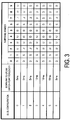
- FIG. 3 is a table illustrating one example of the UL-DL configuration, in the present embodiment.
- D denotes a downlink subframe
- U denotes an uplink subframe
- S denotes a special subframe.
- FIG. 4 is a diagram illustrating a configuration of a slot in the present embodiment.
- a normal Cyclic Prefix (CP) is applied to an OFDM symbol.
- an extended Cyclic Prefix (CP) may be applied to the OFDM symbol.
- the physical signal or the physical channel transmitted in each of the slots is expressed by a resource grid.
- the horizontal axis represents a time axis
- the vertical axis represents a frequency axis.
- the resource grid is defined by multiple subcarriers and multiple OFDM symbols.
- the resource grid is defined by multiple subcarriers and multiple SC-FDMA symbols.
- the number of subcarriers constituting one slot depends on a cell bandwidth.
- the number of OFDM symbols or SC-FDMA symbols constituting one slot is seven.
- Each element within the resource grid is referred to as a resource element.
- the resource element is identified by a subcarrier number, and an OFDM symbol or an SC-FDMA symbol number.
- a resource block is used to express mapping of a certain physical channel (such as the PDSCH or the PUSCH) to resource elements.
- a virtual resource block and a physical resource block are defined.
- a certain physical channel is first mapped to a virtual resource block.
- the virtual resource block is mapped to a physical resource block.
- One physical resource block is defined by seven consecutive OFDM symbols or SC-FDMA symbols in a time domain and by 12 consecutive subcarriers in a frequency domain.
- one physical resource block includes (7 ⁇ 12) resource elements.
- one physical resource block corresponds to one slot in the time domain and corresponds to 180 kHz in the frequency domain. Physical resource blocks are numbered from 0 in the frequency domain.
- FIG. 5 is a diagram illustrating one example of narrow bands in the present embodiment.
- the horizontal axis represents a time axis
- the vertical axis represents a frequency axis.
- a narrow band is constituted of six consecutive physical resource blocks in the frequency domain.
- the terminal device 1 is not capable of performing simultaneous reception on multiple different narrow bands in one slot.
- the terminal device 1 may perform reception on a different narrow band for each of a slot, a subframe, and a subframe set.
- the terminal device 1 is not capable of performing simultaneous transmission on multiple different narrow bands in one slot.
- the terminal device 1 may perform transmission on a different narrow band for each of the slot, the subframe, and the subframe set.
- the terminal device 1 needs a gap in the time domain to switch narrow bands in which the terminal device 1 performs reception processing. Moreover, the terminal device 1 also needs a gap in the time domain to switch narrow bands in which the terminal device 1 performs transmission processing. For example, when the terminal device 1 performs reception processing in a first narrow band in a subframe n, the terminal device 1 may perform reception processing in a different narrow band from the first narrow band in a subframe n+2 without performing the reception processing in any narrow band in a subframe n+1. In other words, when the terminal device 1 performs the reception processing in the first narrow band in the subframe n, the subframe n+1 may be the gap.
- the search space is a set of PDCCH candidates.
- the PDCCH candidates include resources of one or more subframes.
- the terminal device 1 monitors the set of PDCCH candidates in such one or more narrow bands configured by higher layer signaling, for downlink control information.
- monitoring means an attempt to decode each of the PDCCHs in the set of PDCCH candidates in accordance with a format of the downlink control information to be monitored.
- monitoring of a set of PDCCH candidates is also simply referred to as monitoring PDCCHs.
- PDCCH candidate and “MPDCCH candidate” are assumed to mean the same thing.
- set of PDCCH candidates to be monitored are assumed to mean the same thing.
- search space is assumed to mean the same thing.
- MPDCCH search space is assumed to mean the same thing.
- FIG. 6 is a diagram illustrating one example of a search space in the present embodiment.
- one search space includes a PDCCH candidate 60 to a PDCCH candidate 69.
- the PDCCH candidate 60 to the PDCCH candidate 69 are included in an X-th narrow band.
- frequency hopping may be applied to the PDCCH candidates.
- a narrow band including the PDCCH candidate 60 in a first subframe may be different from another narrow band including the PDCCH candidate 60 in a second subframe.
- a gap in the time domain for example, a guard subframe
- the number of resource blocks included in a PDCCH candidate is referred to as an Aggregation Level (AL) of the PDCCH candidate.
- the number of subframes including one PDCCH candidate is referred to as a Repetition Level (RL) of the PDCCH candidate.
- the repetition level of the PDCCH candidates 60, 61, 62, 63, 64, and 65 is represented by RL 0 .
- the repetition level of the PDCCH candidates 66 and 67 is represented by RL 1 .
- the repetition level of the PDCCH candidates 68 and 69 is represented by RL 2 .
- Multiple PDCCH candidates included in the same search space may overlap each other.
- the PDCCH candidate 68 overlaps the PDCCH candidates 60, 61, 62, and 66.
- the multiple subframes including the respective PDCCH candidates 60, 61, 62, and 66 are parts of the multiple subframes including the PDCCH candidate 68.
- two indices of the two resource blocks included in the PDCCH candidates 60, 61, 62, 66, and 68 are identical.
- the position (subframes and resource blocks) of the search space in the time domain and/or in the frequency domain may be configured by a higher layer.
- the position (subframes and resource blocks) of the search space in the time domain and/or in the frequency domain may be configured by the terminal device 1, based on a higher layer message (an RRC message) received from the base station device 3.
- the physical channel may not necessarily be included in a subframe satisfying a given condition.
- “multiple subframes including a physical channel” and “the number of subframes including a physical channel” may be defined in consideration of the subframe(s) satisfying the given condition, or may be defined without consideration of the subframe(s) satisfying the given condition.
- the PDCCH candidates may not necessarily be included in a subframe satisfying the given condition.
- the repetition level of the PDCCH candidate may be defined without consideration of the subframe(s) satisfying the given condition. For example, in a case where a certain PDCCH candidate is included in a subframe 1 to a subframe 10 and two subframes included in the subframe 1 to the subframe 10 satisfy a given condition, the repetition level of the certain PDCCH candidate may be 10.
- the repetition level of a PDCCH candidate may be defined without consideration of the subframe(s) satisfying the given condition. For example, when a certain PDCCH candidate is included in the subframe 1 to the subframe 10 and two subframes included in the subframe 1 to the subframe 10 satisfy the given condition, the repetition level of the certain PDCCH candidate may be 8.
- the above-described given condition may include some or all of a condition (a) to a condition (d) below.
- condition (a) to the condition (d) may use one or more conditions different from the condition (a) to the condition (d), or may use some of the condition (a) to the condition (d).
- "from the X-th subframe” includes the X-th subframe.
- "to the Y-th subframe” includes the Y-th subframe.
- a DRX functionality is configured by a higher layer (RRC) and processed through MAC.
- the DRX functionality controls a PDCCH monitoring activity of the terminal device 1 for the C-RNTI and the SPS C-RNTI of the terminal device 1.
- the DRX functionality controls the monitoring activity of the terminal device 1 for the PDCCH to be used to transmit a DCI format, to which the SPS C-RNTI of the terminal device 1 or CRC parity bits scrambled with the C-RNTI are attached.
- the terminal device 1 may discontinuously monitor the PDCCHs through a DRX operation to be described below. In other cases, the terminal device 1 may continuously monitor PDCCHs.
- the higher layer controls the DRX operation by configuring the following multiple timers and a drxStartOffset value. Whether to configure a drxShortCycleTimer and a shortDRX-Cycle is optional for the higher layer (RRC).
- the base station device 3 may transmit, to the terminal device 1, an RRC message including parameters/information indicating onDurationTimer, drx-InactivityTimer, drx-RetransmissionTimer, longDRX-Cycle, drxShortCycleTimer, shortDRX-Cycle, and the value of drxStartOffset.
- the terminal device 1 may set onDurationTimer, drx-InactivityTimer, drx-RetransmissionTimer, longDRX-Cycle, drxShortCycleTimer, shortDRX-Cycle, and the value of drxStartOffset, based on the received RRC message.
- longDRX-Cycle and shortDRX-Cycle are also collectively referred to as a DRX cycle.
- onDurationTimer indicates the number of consecutive PDCCH subframes from the start of a DRX cycle.
- drx-InactivityTimer indicates the number of consecutive PDCCH subframes subsequent to the subframe, to which the PDCCH indicating initial transmission of uplink data or downlink data to the terminal device 1 is mapped.
- drx-RetransmissionTimer indicates the maximum number of consecutive PDCCH subframes for downlink retransmission expected by the terminal device 1. The same value of drx-RetransmissionTimer is applied to all serving cells.
- the DRX cycle indicates an On Duration iteration cycle.
- An on-duration period is followed by a period in which a PDCCH monitoring inactivity of the terminal device 1 for a C-RNTI and an SPS C-RNTI of the terminal device 1 is enabled.
- FIG. 7 is a diagram illustrating one example of the DRX cycle in the present embodiment.
- the horizontal axis represents a time axis.
- the terminal device 1 monitors PDCCHs in an on-duration period P2200.
- a period P2202 subsequent to the on-duration period P2200 is an inactivity-allowed period.
- the terminal device 1 may not monitor PDCCHs in the period P2202.
- drxShortCycleTimer indicates the number of consecutive subframes in which the terminal device 1 follows a short DRX cycle.
- drxStartOffset indicates a subframe in which the DRX cycle starts.
- An HARQ RTT timer corresponding to a downlink HARQ process relates to the start of a drx-RetransmissionTimer and is managed for each downlink HARQ process.
- the HARQ RTT timer corresponding to a downlink HARQ process indicates the minimum interval from transmission of downlink data to retransmission of the downlink data.
- the HARQ RTT timer corresponding to the downlink HARQ process indicates the minimum number of subframes prior to downlink HARQ retransmission expected by the terminal device 1.
- one downlink HARQ process controls the HARQ of one piece of downlink data (a transport block).
- one downlink HARQ process may control two pieces of downlink data.
- an Active Time may include a period satisfying at least one of a condition (e) to a condition (i) below.
- the conditions used to determine whether a certain period is included in an Active Time are not limited to the condition (e) to the condition (i), may use one or more conditions different from the condition (e) to the condition (i), or may use some of the condition (e) to the condition (i).
- timer keeps running until the timer is stopped or the timer expires. In other cases, the timer is not running. When the timer is not running, the timer has a possibility to be started. When the timer is running, the timer has a possibility to be restarted. The timer is always to be started or restarted from an initial value of the timer.
- the preamble serves as a message 1 in a random access procedure, and is transmitted on a PRACH.
- the preamble that is not selected by the terminal device 1 relates to a contention-based random access procedure.
- the random access response serves as a message 2 in the random access procedure, and is transmitted on a PDSCH.
- the base station device 3 transmits a random access response to the received preamble.
- the terminal device 1 performing the contention-based random access procedure receives the random access response, and then transmits a message 3. After transmitting the message 3, the terminal device 1 monitors a PDCCH relating to a message 4.
- mac-ContentionResolutionTimer indicates the number of consecutive subframes in which the terminal device 1 monitors the PDCCH after the transmission of the message 3.
- FIG. 8 and FIG. 9 are flowcharts illustrating one example of a DRX operation in the present embodiment.
- the terminal device 1 performs the DRX operation for each of the subframes according to the flowcharts in FIG. 8 and FIG. 9 .
- the terminal device 1 If a HARQ RTT timer corresponding to the downlink HARQ process in the current subframe expires and the data of the HARQ process corresponding to the HARQ RTT timer is not decoded successfully (S800), the terminal device 1 starts a drx-RetransmissionTimer for the downlink HARQ process corresponding to the HARQ RTT timer (S802) and processing proceeds to S804. Otherwise (S800), processing of the terminal device 1 proceeds to S804.
- the terminal device 1 stops an onDurationTimer and a drx-InactivityTimer (S806), and processing proceeds to S808. Otherwise (S804), processing of the terminal device 1 proceeds to S808.
- processing of the terminal device 1 proceeds to S810. Otherwise (S808), processing of the terminal device 1 proceeds to S816.
- a short DRX cycle is not configured (S810), the terminal device 1 uses along DRX cycle (S812), and processing proceeds to S816. If the short DRX cycle is configured (S810), the terminal device 1 starts or restarts a drxShortCycleTimer to use the short DRX cycle (S814) and processing proceeds to S816.
- the terminal device 1 uses the long DRX cycle (S818) and processing proceeds to S900 in FIG. 9 . Otherwise (S816), processing of the terminal device 1 proceeds to S900 in FIG. 9 .
- the terminal device 1 monitors the PDCCH in the current subframe (906) and processing proceeds to S908.
- all subframes are PDCCH subframes.
- the terminal device 1 and the base station device 3 identify a PDCCH subframe for a TDD serving cell, based on the UL-DL configuration.
- the terminal device 1 for communicating with the base station device 3 through one TDD serving cell, and the base station device 3 identify (select or determine), as a PDCCH subframe, the subframe indicated as a downlink subframe or a subframe including DwPTS in the UL-DL configuration corresponding to the serving cell.
- the half-duplex FDD operation includes a type A half-duplex FDD operation and a type B half-duplex FDD operation.
- the terminal device 1 may transmit information indicating whether to support the type A half-duplex FDD in the FDD band, to the base station device 3.
- the terminal device 1 may transmit information indicating whether to support the type B half-duplex FDD in the FDD band, to the base station device 3.
- the terminal device 1 is not capable of performing uplink transmission and downlink reception simultaneously.
- a subframe immediately before the subframe in which the terminal device 1 performs uplink transmission and a subframe immediately after the subframe in which the mobile station device 1 performs uplink transmission are each a half-duplex guard subframe.
- the terminal device 1 In the type B half-duplex FDD operation, the terminal device 1 is not capable of performing uplink transmission and downlink reception simultaneously. In the type B half-duplex FDD operation, the terminal device 1 is not capable of performing downlink reception in a subframe immediately before the subframe in which the terminal device 1 performs uplink transmission. For the type B half-duplex FDD operation, the terminal device 1 is not capable of performing downlink reception in a subframe immediately after the subframe in which the terminal device 1 performs uplink transmission.
- the measurement gap is a time interval for the terminal device 1 to perform measurements of cells operating on different frequencies and/or operating in different Radio Access Technologies (RATs).
- the base station device 3 transmits information indicating the period of the measurement gap to the terminal device 1.
- the terminal device 1 configures the period of the measurement gap, based on the information.
- the terminal device 1 terminates the DRX operation for the current subframe. In other words, when at least one of the conditions (j) to (n) is not satisfied, the terminal device 1 need not monitor the PDCCH in the current subframe.
- conditions used in S904 are not limited to the condition (j) to the condition (n). In S904, conditions different from the condition (j) to the condition (n) or some of the condition (j) to the condition (n) may be used.
- the terminal device 1 If the downlink assignment received via the PDCCH indicates downlink transmission or if a downlink assignment is configured for the current subframe (S908), the terminal device 1 starts the HARQ RTT timer for the corresponding downlink HARQ process and stops a drx-RetransmissionTimer for the corresponding downlink HARQ process (S910). Otherwise (S908), processing of the terminal device 1 proceeds to S912.
- the state in which a downlink assignment is configured denotes a state in which semi persistent scheduling is activated by the downlink assignment along with an SPS C-RNTI.
- the terminal device 1 If the downlink assignment or the uplink grant received via the PDCCH indicates initial downlink or uplink transmission (S914), the terminal device 1 starts or restarts the drx-InactivityTimer (S914) and terminates the DRX operation for the current subframe. Otherwise (S912), the terminal device 1 terminates the DRX operation for the current subframe.
- the terminal device 1 configured with DRX does not transmit any periodic SRS when not in the Active Time.
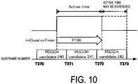
- FIG. 10 is a diagram illustrating one example of monitoring PDCCH candidates in the present embodiment.
- Some of the multiple subframes including a PDCCH candidate 240 are not included in the Active Time, and the other subframes are included in the Active Time.
- a first subframe (T370) of the multiple subframes including the PDCCH candidate 240 is not included in the Active Time.
- the terminal device 1 may not necessarily monitor the PDCCH candidate 240, based on the fact that the first subframe (T370) of the multiple subframes including the PDCCH candidate 240 is not included in the Active Time.
- All the multiple subframes including a PDCCH candidate 241 are included in the Active Time.
- the first subframe (T371) of the multiple subframes including the PDCCH candidate 241 is not included in the Active Time.
- the terminal device 1 may monitor the PDCCH candidate 241, based on the fact that the first subframe (T371) of the multiple subframes including the PDCCH candidate 241 is included in the Active Time.
- the first subframe (T372) of the multiple subframes including a PDCCH candidate 242 is included in the Active Time.
- the terminal device 1 may monitor the PDCCH candidate 242, based on the fact that the first subframe (T372) of the multiple subframes including the PDCCH candidate 242 is included in the Active Time.
- the Active Time may include multiple subframes including the PDCCH candidate 242.
- FIG. 11 is a diagram illustrating one example of PUCCH transmission in the present embodiment.
- a PUCCH 250 is included in a subframe n to a subframe n+Y.
- the PUCCH 250 is used for periodic CQI reporting.
- the terminal device 1 may receive information indicating the PUCCH resources to be used for the periodic CQI reporting, from the base station device 3.
- the information indicating the PUCCH resource to be used for the periodic CQI reporting may indicate at least the subframe to which the PUCCH to be used for the periodic CQI reporting is allocated.
- the terminal device 1 transmits a scheduling request 251, and receives information 252, until and including a subframe n-X.
- the information 252 may include a downlink assignment, an uplink grant, and a DRX command MAC CE.
- the terminal device 1 may receive, from the base station device 3, information (an RRC message) indicating that the terminal device 1 performs setup or release of a higher layer parameter/CQI-mask.
- the terminal device 1 may not report the CQI on the PUCCH 250 included in the subframe n to the sub frame n+Y, irrespective of whether the subframe n+1 to the subframe n+Y are included in the Active Time.
- X may be defined beforehand in a specification, for example.
- X is 5.
- the terminal device 1 may report the CQI on the PUCCH 250 included in the subframe n to the subframe n+Y irrespective of whether the subframe n+1 to the subframe n+Y are included in the Active Time.
- the terminal device 1 may not report the CQI on the PUCCH 250 included in the subframe n to the subframe n+Y irrespective of whether the onDurationTimer is running in the subframe n+1 to the subframe n+Y.
- the terminal device 1 may report the CQI on the PUCCH 250 included in the subframe n to the subframe n+Y irrespective of whether the onDurationTimer is running in the subframe n+1 to the subframe n+Y.
- the terminal device 1 may apply any one of the above-described examples to CQI reporting on the PUCCH 250 irrespective of whether the higher layer parameter/CQI-mask is configured by a higher layer.
- the terminal device 1 transmits a HARQ-ACK on the PUCCH included in a subframe m to a subframe m+Z irrespective of whether some or all of the subframe m to the subframe m+Z are included in the Active Time and whether the onDurationTimer is running in some or all of the subframe m to the subframe m+Z.
- FIG. 12 is a diagram illustrating one example of a method for setting the drx-InactivityTimer and the HARQ RTT timer in the present embodiment.
- FIG. 13 is a diagram illustrating another example of the method for setting a drx-InactivityTimer and a HARQ RTT timer in the present embodiment. Note that the example in FIG. 12 and the example in FIG. 13 may be applied to only one of the drx-InactivityTimer and the HARQ RTT timer. Alternatively, different examples may be applied to the drx-InactivityTimer and the HARQ RTT timer.
- P100 indicates a period while an onDurationTimer is running
- P110 indicates a period while a drx-InactivityTimer is running
- P120 indicates a period while the HARQ RTT timer is running
- P130 indicates a period while the drx-RetransmissionTimer is running.
- a PDCCH candidate 200 is included in a first subframe (a time point T300) to a second subframe (a time point T310)
- a PDCCH candidate 210 is included in the first subframe (the time point T300) to the second subframe (the time point T320).
- the terminal device 1 monitors a search space 240 including the PDCCH candidate 200 and the PDCCH candidate 210.
- Other PDCCH candidates different from the PDCCH candidates 200 and 210 may be included in the search space 240.
- the PDCCH candidate 210 has the highest repetition level among the multiple PDCCH candidates included in the search space 240.
- the terminal device 1 detects a PDCCH 220 from the first subframe (the time point T300) to the second subframe (the time point T310). In FIG. 12 and FIG. 13 , the terminal device 1 decodes a PDSCH 230 included in a fourth subframe (a time point T330) to a fifth subframe (a time point T340), based on the detection of the PDCCH 220.
- the multiple subframes (the fourth subframe and/or the fifth subframe) including the PDSCH 230 may be given by the information included in the PDCCH 220 and/or in the higher layer parameter (an RRC message).
- the number of subframes including the PDSCH 230 may be given by the information included in the PDCCH 220 and/or in the higher layer parameter (the RRC message).
- the terminal device 1 in the last subframe of the subframes including the detected PDCCH 220 or the next subframe of the last subframe, the terminal device 1 (i) sets the drx-InactivityTimer at the sum of A and B, (ii) starts the drx-InactivityTimer, (iii) sets the HARQ RTT timer at the sum of A, C, D, and E, and (iv) starts the HARQ RTT timer.
- the terminal device 1 in the last subframe of the subframes including the PDCCH 210 having the highest repetition level among the multiple PDCCH candidates included in the search space 240, in which the PDCCH 220 has been detected, or in the next subframe of the last subframe, the terminal device 1 (i) sets the drx-InactivityTimer at B, (ii) starts the drx-InactivityTimer, (iii) sets the HARQ RTT timer at the sum of C, D, and E, and (iv) starts the HARQ RTT timer.
- the terminal device 1 when the terminal device 1 detects a PDCCH in the PDCCH candidate 210, the terminal device 1 (i) sets the drx-InactivityTimer at B, (ii) starts the drx-InactivityTimer, (iii) sets the HARQ RTT timer at the sum of C, D, and E, and (iv) starts the HARQ RTT timer, in the last subframe of the subframes including the detected PDCCH 210 or in the next subframe of the last subframe.
- the value of A is given by (i) the difference between the number of subframes including the detected PDCCH 220 and the number of subframes including the PDCCH candidate 210, (ii) the difference between the number of subframes including the PDCCH candidates 200, in which the PDCCH 220 is detected, and the number of subframes including the PDCCH candidate 210, (iii) the difference between the repetition level of the PDCCH candidate 200 and the repetition level of the PDCCH candidate 210, or (iv) the difference between the last subframe including the detected PDCCH 220 and the last subframe including the PDCCH candidate 210.
- the value of B is given by a higher layer.
- the value of B is given by a higher layer parameter.
- the terminal device 1 may receive the higher layer parameter used to indicate the value of B, from the base station device 3.
- C may be defined beforehand in a specification, for example.
- C is 0 or 1.
- the value of C may be given by the information included in the detected PDCCH 220 and/or a higher layer parameter.
- the value of D is the number of subframes including the PDSCH 230.
- the value of D may be given by the information included in the PDCCH 220 and/or a higher layer parameter (an RRC message).
- the information on the value of D, out of the information included in the PDCCH 220, may be the same as or different from the information on the value of C.
- the value of E is given by a higher layer.
- the value of E is given by a higher layer parameter.
- the terminal device 1 may receive the higher layer parameter used to indicate the value of E, from the base station device 3.
- the terminal device 1 is capable of detecting the PDCCH 220 in both the PDCCH candidate 200 and the PDCCH candidate 210. In this case, the terminal device 1 is not capable of identifying which one of the PDCCH candidate 200 and the PDCCH candidate 210 has transmitted the detected PDCCH 220.
- the terminal device 1 when the terminal device 1 detects the PDCCH 220 in the PPDCCH candidate 200, and also when the terminal device 1 detects the PDCCH 220 in the PDCCH candidate 210, the drx-InactivityTimer expires in an identical subframe (a time point T350), and the HARQ RTT timer expires in an identical subframe (a time point T360).
- the terminal device 1 fails to identify which one of the PDCCH candidate 200 and the PDCCH candidate 210 has transmitted the detected PDCCH 220 by using the method in the example in FIG. 12 and the example in FIG.
- the base station device 3 is capable of learning the state of the drx-InactivityTimer and/or the HARQ RTT timer in the terminal device 1 with accuracy, by the terminal device 1 using the example in FIG. 12 or the example in FIG. 13 and by the base station device 3 assuming that the terminal device 1 is using the example in FIG. 12 or the example in FIG. 13 .
- the base station device 3 is capable of efficiently controlling the DRX of the terminal device 1, and the terminal device 1 and the base station device 3 are capable of communicating efficiently.
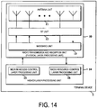
- FIG. 14 is a schematic block diagram illustrating a configuration of the terminal device 1 in the present embodiment.
- the terminal device 1 is configured to include a radio transmission and reception unit 10 and a higher layer processing unit 14.
- the radio transmission and reception unit 10 is configured to include an antenna unit 11, a Radio Frequency (RF) unit 12, and a baseband unit 13.
- the higher layer processing unit 14 is configured to include a medium access control layer processing unit 15 and a radio resource control layer processing unit 16.
- the radio transmission and reception unit 10 is also referred to as a transmission unit, a reception unit, or a physical layer processing unit.
- the higher layer processing unit 14 outputs uplink data (a transport block) generated by a user operation or the like, to the radio transmission and reception unit 10.
- the higher layer processing unit 14 performs processing of the Medium Access Control (MAC) layer, a Packet Data Convergence Protocol (PDCP) layer, a Radio Link Control (RLC) layer, and the Radio Resource Control (RRC) layer.
- MAC Medium Access Control
- PDCP Packet Data Convergence Protocol
- RLC Radio Link Control
- RRC Radio Resource Control
- the medium access control layer processing unit 15 included in the higher layer processing unit 14 performs processing of the medium access control layer.
- the medium access control layer processing unit 15 controls HARQ in accordance with the various pieces of configuration information/parameters managed by the radio resource control layer processing unit 16.
- the medium access control layer processing unit 15 manages multiple HARQ entities, multiple HARQ processes, and multiple HARQ buffers.
- the medium access control layer processing unit 15 identifies (selects, determines) a PDCCH subframe.
- the medium access control layer processing unit 15 performs processing of DRX, based on the PDCCH subframe.
- the medium access control layer processing unit 15 manages a timer relating to DRX, based on the PDCCH subframe.
- the medium access control layer processing unit 15 instructs the radio transmission and reception unit 10 to monitor the PDCCH in the subframe.
- the monitoring of the PDCCH denotes an attempt to decode the PDCCH in accordance with a DCI format.
- the radio resource control layer processing unit 16 included in the higher layer processing unit 14 performs the processing of the radio resource control layer.
- the radio resource control layer processing unit 16 manages various pieces of configuration information/parameters of the terminal device 1.
- the radio resource control layer processing unit 16 sets the various pieces of configuration information/parameters in accordance with RRC layer signaling received from the base station device 3. Specifically, the radio resource control layer processing unit 16 sets the various pieces of configuration information/parameters in accordance with the information indicating the various pieces of configuration information/parameters that have been received from the base station device 3.
- the radio transmission and reception unit 10 performs processing of the physical layer, such as modulation, demodulation, coding, and decoding.
- the radio transmission and reception unit 10 demultiplexes, demodulates, and decodes a signal received from the base station device 3, and outputs the information resulting from the decoding to the higher layer processing unit 14.
- the radio transmission and reception unit 10 modulates and codes data to generate a transmit signal, and transmits the transmit signal to the base station device 3.
- the RF unit 12 converts (down-converts) a signal received through the antenna unit 11 into a baseband signal by orthogonal demodulation and removes unnecessary frequency components.
- the RF unit 12 outputs a processed analog signal to the baseband unit.
- the baseband unit 13 converts the analog signal that has been input from the RF unit 12, into a digital signal.
- the baseband unit 13 removes a portion corresponding to a Cyclic Prefix (CP) from the digital signal that has been converted, performs Fast Fourier Transform (FFT) on the signal from which the CP has been removed, and extracts a signal of a frequency domain.
- CP Cyclic Prefix
- FFT Fast Fourier Transform
- the baseband unit 13 performs Inverse Fast Fourier Transform (IFFT) on data, generates SC-FDMA symbols, attaches a CP to the generated SC-FDMA symbols, generates a baseband digital signal, and converts the baseband digital signal into an analog signal.
- IFFT Inverse Fast Fourier Transform
- the baseband unit 13 outputs such a converted analog signal to the RF unit 12.
- the RF unit 12 removes unnecessary frequency components from the analog signal that has been input from the baseband unit 13 by using a low-pass filter, up-converts the analog signal into a signal of a carrier frequency, and transmits such an up-converted signal via the antenna unit 11. Moreover, the RF unit 12 amplifies the power. Moreover, the RF unit 12 may have a function of controlling the transmit power.
- the RF unit 12 is also referred to as a transmit power control unit.
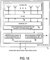
- FIG. 15 is a schematic block diagram illustrating a configuration of the base station device 3 in the present embodiment.
- the base station device 3 is configured to include a radio transmission and reception unit 30 and a higher layer processing unit 34.
- the radio transmission and reception unit 30 is configured to include an antenna unit 31, an RF unit 32, and a baseband unit 33.
- the higher layer processing unit 34 is configured to include a medium access control layer processing unit 35 and a radio resource control layer processing unit 36.
- the radio transmission and reception unit 30 is also referred to as a transmission unit, a reception unit, or a physical layer processing unit.
- the higher layer processing unit 34 performs processing of the Medium Access Control (MAC) layer, a Packet Data Convergence Protocol (PDCP) layer, a Radio Link Control (RLC) layer, and the Radio Resource Control (RRC) layer.
- MAC Medium Access Control
- PDCP Packet Data Convergence Protocol
- RLC Radio Link Control
- RRC Radio Resource Control
- the medium access control layer processing unit 35 included in the higher layer processing unit 34 performs the processing of the Medium Access Control layer.
- the medium access control layer processing unit 15 controls HARQ in accordance with the various pieces of configuration information/parameters managed by the radio resource control layer processing unit 16.
- the medium access control layer processing unit 15 generates an ACK/NACK and HARQ information with respect to uplink data (UL-SCH).
- the ACK/NACK and HARQ information with respect to the uplink data (UL-SCH) are transmitted to the terminal device 1 on the PHICH or the PDCCH.
- the radio resource control layer processing unit 36 included in the higher layer processing unit 34 performs the processing of the Radio Resource Control layer.
- the radio resource control unit 36 generates, or acquires from a higher node, downlink data (a transport block) arranged on a physical downlink shared channel, system information, an RRC message, a MAC Control Element (CE), and the like, and outputs the generated or acquired data to the radio transmission and reception unit 30.
- the radio resource control layer processing unit 36 manages various pieces of configuration information/parameters for each of the terminal devices 1.
- the radio resource control layer processing unit 36 may set various pieces of configuration information/parameters for each of the terminal devices 1 via the higher layer signaling. In other words, the radio resource control layer processing unit 36 transmits/broadcasts information indicating various pieces of configuration information/parameters.
- the function of the radio transmission and reception unit 30 is similar to the function of the radio transmission and reception unit 10, and hence description thereof is omitted.
- the terminal device 1 is capable of efficiently communicating with the base station device 3.
- a program running on each of the base station device 3 and the terminal device 1 in the present invention may be a program for controlling a Central Processing Unit (CPU) and the like (a program for causing a computer to operate) to enable the functions in the above-described embodiment of the present invention.
- Information handled in these devices is temporarily stored in a Random Access Memory (RAM) while being processed. Subsequently, the information is stored in various types of Read Only Memory (ROM), such as a flash ROM and a Hard Disk Drive (HDD), and is read by the CPU to be modified or rewritten, as appropriate.
- ROM Read Only Memory
- HDD Hard Disk Drive
- the terminal device 1 and the base station device 3 in the above-described embodiment may be partially achieved by a computer.
- This configuration may be achieved by recording a program for enabling such control functions on a computer-readable medium and causing a computer system to read the program recorded in the recording medium for execution.
- the "computer system” herein refers to a computer system built into the terminal device 1 or the base station device 3, and the computer system includes an OS and hardware components, such as a peripheral device.
- the "computer-readable recording medium” refers to a portable medium such as a flexible disk, a magneto-optical disk, a ROM, and a CD-ROM, and a storage device such as a hard disk built into the computer system.
- the "computer-readable recording medium” may include a medium for dynamically holding a program for a short period of time, such as a communication line that is used to transmit the program over a network such as the Internet or over a communication circuit such as a telephone circuit, and a medium for holding, in such a case, a program for a fixed period of time, such as a volatile memory within a computer system that functions as a server or a client.
- the program may be configured to enable some of the functions described above, and may also be configured to enable the functions described above in combination with a program already recorded in a computer system.
- the base station device 3 in the above-described embodiments can be achieved as an aggregation (a device group) including multiple devices.
- Devices constituting the device group may be each equipped with some or all portions of each function or each functional block of the base station device 3 in the above-described embodiments.
- the device group may include at least a general function or a general functional block of the base station device 3.
- the terminal device 1 in the above-described embodiments is also capable of communicating with the base station device, as an aggregation.
- the base station device 3 in the above-described embodiments may be an Evolved Universal Terrestrial Radio Access Network (EUTRAN). Furthermore, the base station device 3 in the above-described embodiments may have some or all portions of the functionality of a node higher than an eNodeB.
- EUTRAN Evolved Universal Terrestrial Radio Access Network
- each of the terminal device 1 and the base station device 3 in the above-described embodiments may be achieved as an LSI, which is a typical integrated circuit, or may be achieved as a chip set.
- the functional blocks of each of the terminal device 1 and the base station device 3 may be individually achieved as a chip, or some or all of the functional blocks may be integrated into a chip.
- a circuit integration technique is not limited to the LSI, and the integrated circuit may be achieved with a dedicated circuit or a general-purpose processor.
- an advanced integrated circuit may be applicable.
- the terminal device has been described as one example of a communication device, but is not limited to this configuration.
- the above-described terminal device is applicable to a fixed-type or a stationary-type electronic apparatus installed indoors or outdoors, for example, a terminal device or a communication device, such as an Audio-Video (AV) apparatus, a kitchen appliance, a cleaning or washing machine, an air-conditioning apparatus, office equipment, a vending machine, and other household apparatuses.
- AV Audio-Video
- Some aspects of the present invention are applicable to a terminal device, a communication method, and an integrated circuit where the terminal device and a base station device are demanded to communicate in an efficient manner.
Landscapes
- Engineering & Computer Science (AREA)
- Signal Processing (AREA)
- Computer Networks & Wireless Communication (AREA)
- Mobile Radio Communication Systems (AREA)
Abstract
Description
- The present invention relates to a terminal device, a communication method, and an integrated circuit.
This application claims priority based onJP 2015-123365 filed on June 19, 2015 - In the 3rd Generation Partnership Project (3GPP), a radio access method and a radio network for cellular mobile communications (hereinafter referred to as "Long Term Evolution (LTE)", "Evolved Universal Terrestrial Radio Access (EUTRA)", or "Evolved Universal Terrestrial Radio Access Network (EUTRAN)") have been studied. In LTE, a base station device is also referred to as an evolved NodeB (eNodeB), and a terminal device is also referred to as User Equipment (UE). LTE is a cellular communication system in which an area is divided into multiple cells to form a cellular pattern, each of the cells being served by a base station device. A single base station device may manage multiple cells.
- LTE supports Time Division Duplex (TDD). LTE that employs a TDD scheme is also referred to as TD-LTE or LTE TDD. In TDD, uplink signals and downlink signals are time-division multiplexed. In addition, LTE supports Frequency Division Duplex (FDD).
- In LTE, Downlink Control Information (DCI) is transmitted using a Physical Downlink Control CHannel (PDCCH) and an Enhanced Physical Downlink Control CHannel (EPDCCH). DCI is used for scheduling of a Physical Downlink Shared CHannel (PDSCH) in a cell.
- A technique for transmitting a Machine type communication Physical Downlink Control CHannel (MPDCCH) in multiple subframes has been studied in the 3GPP to improve a downlink cell coverage (NPL 1). In addition, a technique for transmitting a Physical Uplink Control CHannel (PUCCH) in multiple subframes has been studied in the 3GPP to improve an uplink cell coverage (NPL 2).
-
- NPL 1: "R1-153458 WF on principle of M-PDCCH search space design", 3GPP TSG RAN WG1 #81, 25th-29th, May 2015.
- NPL 2: "R1-153571 Way Forward on PUCCH enhancement for MTC", 3GPP TSG RAN WG1 #81, 25th-29th, May 2015.
- According to some aspects of the present invention, a terminal device is capable of efficiently communicating with a base station device on a physical channel included in multiple subframes, an integrated circuit mounted on the terminal device, and a communication method used by the terminal device.
-
- (1) To accomplish the object described above, according to some aspects of the present invention, the following measures are taken. Specifically, according to a first aspect of the present invention, a terminal device includes: a transmission unit configured to transmit uplink control information including channel state information and a HARQ-ACK on a PUCCH; and a medium access control layer processing unit configured to perform a DRX functionality for controlling monitoring of an MPDCCH. In a case that a CQI-mask is not setup by a higher layer and a subframe n is assumed to be included in an Active Time in consideration of a scheduling request transmitted until and including a subframe n-5 and information received until and including the subframe n-5, the channel state information is transmitted on the PUCCH in the subframe n and a subframe n+1, irrespective of whether the subframe n+1 is included in the Active Time.
- (2) According to a second aspect of the present invention, a communication method used by a terminal device includes: transmitting uplink control information including channel state information and a HARQ-ACK on a PUCCH; and performing a DRX functionality for controlling monitoring of an MPDCCH. In a case that a CQI-mask is not setup by a higher layer and a subframe n is assumed to be included in an Active Time in consideration of a scheduling request transmitted until and including a subframe n-5 and information received until and including the subframe n-5, the channel state information is transmitted on the PUCCH in the subframe n and a subframe n+1, irrespective of whether the subframe n+1 is included in the Active Time.
- (3) According to a third aspect of the present invention, an integrated circuit mounted on a terminal device includes: a transmission circuit configured to transmit uplink control information including channel state information and a HARQ-ACK on a PUCCH; and a medium access control layer processing circuit configured to perform a DRX functionality for controlling monitoring of an MPDCCH. In a case that a CQI-mask is not setup by a higher layer and a subframe n is assumed to be included in an Active Time in consideration of a scheduling request transmitted until and including a subframe n-5 and information received until and including the subframe n-5, the channel state information is transmitted on the PUCCH in the subframe n and a subframe n+1, irrespective of whether the subframe n+1 is included in the Active Time.
- According to some aspects of the present invention, a terminal device and a base station device are capable of efficiently communicating on physical channels included in multiple subframes.
-
-
FIG. 1 is a conceptual diagram of a radio communication system in the present embodiment. -
FIG. 2 is a diagram illustrating a schematic configuration of a radio frame in the present embodiment. -
FIG. 3 is a table illustrating one example of a UL-DL configuration in the present embodiment. -
FIG. 4 is a diagram illustrating a configuration of a slot in present embodiment. -
FIG. 5 is a diagram illustrating one example of narrow bands in the present embodiment. -
FIG. 6 is a diagram illustrating one example of a search space in the present embodiment. -
FIG. 7 is a diagram illustrating one example of a DRX cycle in the present embodiment. -
FIG. 8 is a flowchart illustrating one example of a DRX operation in the present embodiment. -
FIG. 9 is a flowchart illustrating the one example of the DRX operation in the present embodiment. -
FIG. 10 is a diagram illustrating one example of monitoring PDCCH candidates in the present embodiment. -
FIG. 11 is a diagram illustrating one example of transmission on a PUCCH in the present embodiment. -
FIG. 12 is a diagram illustrating one example of a method for setting a drx-InactivityTimer and an HARQ RTT timer in the present embodiment. -
FIG. 13 is a diagram illustrating another example of the method for setting the drx-InactivityTimer and the HARQ RTT timer in the present embodiment. -
FIG. 14 is a schematic block diagram illustrating a configuration of aterminal device 1 in the present embodiment. -
FIG. 15 is a schematic block diagram illustrating a configuration of abase station device 3 in the present embodiment. - An embodiment of the present invention will be described below.
-
FIG. 1 is a conceptual diagram of a radio communication system in the present embodiment. InFIG. 1 , the radio communication system includesterminal devices 1A to 1C and abase station device 3. Hereinafter,terminal devices 1 A to 1C are each referred to as aterminal device 1. - The present embodiment may be applied to an RRC_CONNECTED state, or only to the
terminal device 1 in an RRC_CONNECTED mode. The present embodiment may be applied to an RRC_IDLE state or only to theterminal device 1 in the RRC_IDLE state. The present embodiment may be applied to both the RRC_CONNECTED state or theterminal device 1 in the RRC_CONNECTED mode, and the RRC_IDLE state or theterminal device 1 in the RRC_IDLE state. - In the present embodiment, one serving cell is configured for the
terminal device 1. The one serving cell may be a primary cell. The one serving cell may be a cell on which theterminal device 1 is camping. The primary cell is a cell in which an initial connection establishment procedure has been performed, a cell in which a connection re-establishment procedure has started, or a cell indicated as a primary cell in a handover procedure. - In the downlink, a carrier corresponding to the serving cell is referred to as a downlink component carrier. In the uplink, a carrier corresponding to the serving cell is referred to as an uplink component carrier. The downlink component carrier and the uplink component carrier are collectively referred to as a component carrier. In FDD, the uplink component carrier and the downlink component carrier correspond to different carrier frequencies. In TDD, the uplink component carrier and the downlink component carrier correspond to the same carrier frequencies.
- In the downlink, one independent HARQ entity exists for each serving cell (downlink component carrier). The HARQ entity manages multiple HARQ processes in parallel. Each of the HARQ processes instructs a physical layer to receive data based on a received downlink assignment (downlink control information).
- In the downlink, at least one transport block is generated for each of one or more Transmission Time Intervals (TTIs) for each serving cell. The transport block and HARQ retransmission of the transport block are mapped to one serving cell. Note that, in LTE, a TTI serves as a subframe. The transport block in the downlink is MAC layer data transmitted on the DownLink Shared CHannel (DL-SCH).
- In the present embodiment, in the uplink, "transport block", "MAC Protocol Data Unit (PDU)", "MAC layer data", "DL-SCH", "DL-SCH data", and "downlink data" are assumed to mean the same thing.
- Physical channels and physical signals in the present embodiment will be described.
- One physical channel is mapped to one or more subframes. In the present embodiment, "one physical channel included in multiple subframes", "one physical channel mapped to multiple subframes", "one physical channel including resources of multiple subframes", and "one physical channel repeatedly transmitted over multiple subframes" are assumed to mean the same thing.
- In uplink radio communication from the
terminal device 1 to thebase station device 3, the following uplink physical channels are used. The uplink physical channels are used to transmit information output from a higher layer. - Physical Uplink Control CHannel (PUCCH)
- Physical Uplink Shared CHannel (PUSCH)
- Physical Random Access CHannel (PRACH)
- The PUCCH is used to transmit Uplink Control Information (UCI). The uplink control information includes: downlink Channel State Information (CSI); a Scheduling Request (SR) to be used to request a PUSCH (UpLink-Shared CHannel (UL-SCH)) resource for initial transmission; and a Hybrid Automatic Repeat reQuest ACKnowledgement (HARQ-ACK) for downlink data (a transport block, a medium access control protocol data unit (MAC PDU), a DownLink-Shared CHannel (DL-SCH), or a Physical Downlink Shared CHannel (PDSCH)). The HARQ-ACK indicates an ACKnowledgement (ACK) or a Negative-ACKnowledgement (NACK). The HARQ-ACK is also referred to as ACK/NACK, HARQ feedback, HARQ acknowledge, or HARQ control information.
- The scheduling request includes a positive scheduling request or a negative scheduling request. The positive scheduling request indicates requesting of a UL-SCH resource for initial transmission. The negative scheduling request indicates not requesting of any UL-SCH resource for initial transmission.
- The PUSCH is used to transmit uplink data (UpLink-Shared CHannel (UL-SCH)). Furthermore, the PUSCH may be used to transmit the HARQ-ACK and/or channel state information along with the uplink data. Furthermore, the PUSCH may be used to transmit only the channel state information. Furthermore, the PUSCH may be used to transmit only the HARQ-ACK and the channel state information.
- Here, the
base station device 3 and theterminal device 1 exchange signals in (transmit and receive a signal to and from) higher layers. For example, thebase station device 3 and theterminal device 1 may transmit and receive RRC signaling in a Radio Resource Control (RRC) layer. Moreover, thebase station device 3 and theterminal device 1 may transmit and receive a Medium Access Control (MAC) CE in a MAC layer. Here, the RRC signaling and/or the MAC CE are/is also referred to as higher layer signaling. The RRC signaling and/or the MAC CE are/is included in a transport block. - In the present embodiment, "RRC signaling", "RRC layer information", "RRC layer signal" "RRC layer parameter", "RRC message", and "RRC information element" are assumed to mean the same thing.
- The PUSCH is used to transmit the RRC signaling and the MAC CE. Here, the RRC signaling transmitted from the
base station device 3 may be signaling common to multipleterminal devices 1 in a cell. Alternatively, the RRC signaling transmitted from thebase station device 3 may be signaling dedicated to a certain terminal device 1 (also referred to as dedicated signaling). In other words, user device-specific information is transmitted using the signaling dedicated to a certainterminal device 1. - The PRACH is used to transmit a random access preamble. The PRACH is used to indicate an initial connection establishment procedure, a handover procedure, a connection re-establishment procedure, synchronization (timing adjustment) for uplink transmission, and the request for a PUSCH (UL-SCH) resource.
- The following uplink physical signal is used for uplink radio communication. The uplink physical signal is not used to transmit information output from the higher layers, but is used in the physical layer.
- UpLink Reference Signal (UL RS)
- The following downlink physical channels are used for downlink radio communication from the
base station device 3 to theterminal device 1. The downlink physical channels are used to transmit the information output from the higher layers. - Physical Broadcast CHannel (PBCH)
- Physical Control Format Indicator CHannel (PCFICH)
- Physical Hybrid Automatic Repeat Request Indicator CHannel (PHICH)
- Physical Downlink Control CHannel (PDCCH)
- Enhanced Physical Downlink Control CHannel (EPDCCH)
- Machine type communication Physical Downlink Control CHannel (MPDCCH)
- Physical Downlink Shared CHannel (PDSCH)
- Physical Multicast CHannel (PMCH)
- The PBCH is used to broadcast a Master Information Block (MIB), or a Broadcast CHannel (BCH), which is commonly used by the
terminal devices 1. - The PCFICH is used to transmit information indicating a region (OFDM symbols) to be used for transmitting the PDCCH.
- The PHICH is used to transmit an HARQ indicator (HARQ feedback or response information) indicating an ACKnowledgement (ACK) or a Negative ACKnowledgement (NACK) with respect to the uplink data (UpLink Shared CHannel (UL-SCH)) received by the
base station device 3. - The PDCCH, the EPDCCH, and the MPDCCH are used for transmitting Downlink Control Information (DCI). In the present embodiment, the "PDCCH" is assumed to include the "EPDCCH" and the "MPDCCH", for the sake of convenience. The downlink control information is also referred to as a DCI format. The downlink control information transmitted on one PDCCH includes a downlink grant and HARQ information, or an uplink grant and HARQ information. The downlink grant is also referred to as a downlink assignment or a downlink allocation. The downlink assignment and the uplink grant are not transmitted together on one PDCCH.
- The downlink assignment is used for scheduling a single PDSCH within a single cell. The downlink assignment may be used for scheduling the PDSCH within the same subframe as the subframe in which the downlink grant is transmitted. The downlink assignment may be used for scheduling the PDSCH included in the subframe in which the downlink grant is transmitted and in one or more subsequent subframes.
- The uplink grant is used for scheduling a single PUSCH within a single cell. The uplink grant may be used for scheduling a PUSCH included in one or more subframes subsequent to the subframe in which the uplink grant is transmitted.
- Cyclic Redundancy Check (CRC) parity bits attached to the downlink control information transmitted on one PDCCH are scrambled with a Cell-Radio Network Temporary Identifier (C-RNTI), a Semi Persistent Scheduling (SPS) C-RNTI, or a Temporary C-RNTI. The C-RNTI and the SPS C-RNTI serve as identifiers for identifying a terminal device within a cell. The Temporary C-RNTI serves as an identifier for identifying the
terminal device 1 that has transmitted a random access preamble in a contention-based random access procedure. - The C-RNTI and the Temporary C-RNTI are used to control PDSCH transmission or PUSCH transmission in a single subframe. The SPS C-RNTI is used to periodically allocate PDSCH or PUSCH resources.
- The PDSCH is used to transmit downlink data (DownLink Shared CHannel (DL-SCH)).
- The PMCH is used to transmit multicast data (Multicast CHannel (MCH)).
- The following downlink physical signals are used in the downlink radio communication. The downlink physical signals are not used to transmit the information output from the higher layers, but are used in the physical layer.
- Synchronization Signal (SS)
- DownLink Reference Signal (DL RS)
- The synchronization signal is used for the
terminal device 1 to be synchronized in frequency and time domains for downlink. In the TDD scheme, the synchronization signal is mapped tosubframes subframes - The downlink reference signal is used for the
terminal device 1 to perform channel compensation of the downlink physical channel. The downlink reference signal is used for theterminal device 1 to calculate the downlink channel state information. - In the present embodiment, the following five types of downlink reference signals are used.
- Cell-specific Reference Signal (CRS)
- UE-specific Reference Signal (URS) associated with the PDSCH
- DeModulation Reference Signal (DMRS) associated with the EPDCCH
- Non-Zero Power Channel State Information-Reference Signal (NZP CSI-RS)
- Zero Power Channel State Information-Reference Signal (ZP CSI-RS)
- Multimedia Broadcast and Multicast Service over Single Frequency Network Reference Signal (MBSFN RS)
- Positioning Reference Signal (PRS)
- The downlink physical channel and the downlink physical signal are collectively referred to as a downlink signal. The uplink physical channel and the uplink physical signal are collectively referred to as an uplink signal. The downlink physical channel and the uplink physical channel are collectively referred to as a physical channel. The downlink physical signal and the uplink physical signal are collectively referred to as a physical signal.
- The BCH, the MCH, the UL-SCH, and the DL-SCH serve as transport channels. A channel used in the Medium Access Control (MAC) layer is referred to as a transport channel. The unit of the transport channel used in the MAC layer is also referred to as a Transport Block (TB) or a MAC Protocol Data Unit (PDU). Control of a Hybrid Automatic Repeat reQuest (HARQ) is performed for each transport block in the MAC layer. The transport block is a unit of data delivered by the MAC layer delivers to the physical layer. In the physical layer, the transport block is mapped to a codeword, and coding processing is performed for each codeword.
- A structure of a radio frame in the present embodiment will be described.
- In LTE, two radio frame structures are supported. The two radio frame structures are
Frame structure Type 1 andFrame structure Type 2.Frame structure Type 1 is applicable to FDD.Frame structure Type 2 is applicable to TDD. -
FIG. 2 is a diagram illustrating a schematic configuration of the radio frame in the present embodiment. InFIG. 2 , the horizontal axis represents a time axis. Moreover, each of the radio frames ofType 1 andType 2 is 10 ms in length and is defined by 10 subframes. Each of the subframes is 1 ms in length and is defined by two consecutive slots. Each of the slots is 0.5 ms in length. The i-th subframe in a radio frame includes a (2 × i)-th slot and a (2 × i + 1)-th slot. - The following three types of subframes are defined for
Frame structure Type 2. - Downlink subframe
- Uplink subframe
- Special subframe
- The downlink subframe serves as a subframe reserved for downlink transmission. The uplink subframe serves as a subframe reserved for uplink transmission. The special subframe includes three fields. The three fields include a Downlink Pilot Time Slot (DwPTS), a Guard Period (GP), and an Uplink Pilot Time Slot (UpPTS). The total length of the DwPTS, the GP, and the UpPTS is 1 ms. The DwPTS is a field reserved for downlink transmission. The UpPTS is a field reserved for uplink transmission. The GP is a field in which neither the downlink transmission nor the uplink transmission is performed. Note that the special subframe may include only the DwPTS and the GP, or may include only the GP and the UpPTS.
- A radio frame of
Frame structure Type 2 includes at least the downlink subframe, the uplink subframe, and the special subframe. The configuration of the radio frame ofFrame structure Type 2 is indicated by an UpLink-DownLink configuration (UL-DL configuration). Theterminal device 1 receives information indicating the UL-DL configuration from thebase station device 3.FIG. 3 is a table illustrating one example of the UL-DL configuration, in the present embodiment. InFIG. 3 , D denotes a downlink subframe, U denotes an uplink subframe, and S denotes a special subframe. - A configuration of a slot in the present embodiment will be described below.
-
FIG. 4 is a diagram illustrating a configuration of a slot in the present embodiment. In the present embodiment, a normal Cyclic Prefix (CP) is applied to an OFDM symbol. Note that an extended Cyclic Prefix (CP) may be applied to the OFDM symbol. The physical signal or the physical channel transmitted in each of the slots is expressed by a resource grid. InFIG. 4 , the horizontal axis represents a time axis, and the vertical axis represents a frequency axis. In downlink, the resource grid is defined by multiple subcarriers and multiple OFDM symbols. In uplink, the resource grid is defined by multiple subcarriers and multiple SC-FDMA symbols. The number of subcarriers constituting one slot depends on a cell bandwidth. The number of OFDM symbols or SC-FDMA symbols constituting one slot is seven. Each element within the resource grid is referred to as a resource element. The resource element is identified by a subcarrier number, and an OFDM symbol or an SC-FDMA symbol number. - A resource block is used to express mapping of a certain physical channel (such as the PDSCH or the PUSCH) to resource elements. For the resource block, a virtual resource block and a physical resource block are defined. A certain physical channel is first mapped to a virtual resource block. Thereafter, the virtual resource block is mapped to a physical resource block. One physical resource block is defined by seven consecutive OFDM symbols or SC-FDMA symbols in a time domain and by 12 consecutive subcarriers in a frequency domain. Hence, one physical resource block includes (7 × 12) resource elements. Furthermore, one physical resource block corresponds to one slot in the time domain and corresponds to 180 kHz in the frequency domain. Physical resource blocks are numbered from 0 in the frequency domain.
- Hereinafter, narrow bands to be applicable in the present invention will be described.
-
FIG. 5 is a diagram illustrating one example of narrow bands in the present embodiment. InFIG. 5 , the horizontal axis represents a time axis, and the vertical axis represents a frequency axis. In a slot, a narrow band is constituted of six consecutive physical resource blocks in the frequency domain. Theterminal device 1 is not capable of performing simultaneous reception on multiple different narrow bands in one slot. Theterminal device 1 may perform reception on a different narrow band for each of a slot, a subframe, and a subframe set. Theterminal device 1 is not capable of performing simultaneous transmission on multiple different narrow bands in one slot. Theterminal device 1 may perform transmission on a different narrow band for each of the slot, the subframe, and the subframe set. - The
terminal device 1 needs a gap in the time domain to switch narrow bands in which theterminal device 1 performs reception processing. Moreover, theterminal device 1 also needs a gap in the time domain to switch narrow bands in which theterminal device 1 performs transmission processing. For example, when theterminal device 1 performs reception processing in a first narrow band in a subframe n, theterminal device 1 may perform reception processing in a different narrow band from the first narrow band in a subframe n+2 without performing the reception processing in any narrow band in asubframe n+ 1. In other words, when theterminal device 1 performs the reception processing in the first narrow band in the subframe n, the subframe n+1 may be the gap. - Hereinafter, a search space to be applicable in the present invention will be described. The search space is a set of PDCCH candidates. The PDCCH candidates include resources of one or more subframes.
- The
terminal device 1 monitors the set of PDCCH candidates in such one or more narrow bands configured by higher layer signaling, for downlink control information. Here, monitoring means an attempt to decode each of the PDCCHs in the set of PDCCH candidates in accordance with a format of the downlink control information to be monitored. In the present embodiment, monitoring of a set of PDCCH candidates is also simply referred to as monitoring PDCCHs. - In the present embodiment, "PDCCH candidate" and "MPDCCH candidate" are assumed to mean the same thing. In the present embodiment, "set of PDCCH candidates to be monitored", "set of MPDCCH candidates to be monitored", "search space" "PDCCH search space", "MPDCCH search space", "UE-specific search space", "PDCCH UE-specific search space", and "MPDCCH UE-specific search space" are assumed to mean the same thing.
-
FIG. 6 is a diagram illustrating one example of a search space in the present embodiment. - In
FIG. 6 , one search space includes aPDCCH candidate 60 to aPDCCH candidate 69. ThePDCCH candidate 60 to thePDCCH candidate 69 are included in an X-th narrow band. InFIG. 6 , frequency hopping may be applied to the PDCCH candidates. For example, a narrow band including thePDCCH candidate 60 in a first subframe may be different from another narrow band including thePDCCH candidate 60 in a second subframe. To change a narrow band including a PDCCH candidate, a gap in the time domain (for example, a guard subframe) is needed. - In a slot, the number of resource blocks included in a PDCCH candidate is referred to as an Aggregation Level (AL) of the PDCCH candidate. The aggregation level of the
PDCCH candidates PDCCH candidates - The number of subframes including one PDCCH candidate is referred to as a Repetition Level (RL) of the PDCCH candidate. The repetition level of the
PDCCH candidates PDCCH candidates PDCCH candidates - Multiple PDCCH candidates included in the same search space may overlap each other. For example, in
FIG. 6 , thePDCCH candidate 68 overlaps thePDCCH candidates respective PDCCH candidates PDCCH candidate 68. In the frequency domain, two indices of the two resource blocks included in thePDCCH candidates - The position (subframes and resource blocks) of the search space in the time domain and/or in the frequency domain may be configured by a higher layer. The position (subframes and resource blocks) of the search space in the time domain and/or in the frequency domain may be configured by the
terminal device 1, based on a higher layer message (an RRC message) received from thebase station device 3. - The physical channel may not necessarily be included in a subframe satisfying a given condition. In the present embodiment, "multiple subframes including a physical channel" and "the number of subframes including a physical channel" may be defined in consideration of the subframe(s) satisfying the given condition, or may be defined without consideration of the subframe(s) satisfying the given condition.
- The PDCCH candidates may not necessarily be included in a subframe satisfying the given condition. The repetition level of the PDCCH candidate may be defined without consideration of the subframe(s) satisfying the given condition. For example, in a case where a certain PDCCH candidate is included in a
subframe 1 to asubframe 10 and two subframes included in thesubframe 1 to thesubframe 10 satisfy a given condition, the repetition level of the certain PDCCH candidate may be 10. - The repetition level of a PDCCH candidate may be defined without consideration of the subframe(s) satisfying the given condition. For example, when a certain PDCCH candidate is included in the
subframe 1 to thesubframe 10 and two subframes included in thesubframe 1 to thesubframe 10 satisfy the given condition, the repetition level of the certain PDCCH candidate may be 8. - For example, the above-described given condition may include some or all of a condition (a) to a condition (d) below.
- Condition (a): the subframe is reserved as an MBSFN subframe
- Condition (b): in TDD, the subframe is an uplink subframe
- Condition (c): the subframe is a gap (a guard subframe) for frequency hopping applied to the PDCCH candidate
- Condition (d): the subframe is a part of a configured measurement gap
- Note that the conditions included in the above-described given conditions are not necessarily limited to the condition (a) to the condition (d), may use one or more conditions different from the condition (a) to the condition (d), or may use some of the condition (a) to the condition (d).
- In the present embodiment, "from the X-th subframe" includes the X-th subframe. In the present embodiment, "to the Y-th subframe" includes the Y-th subframe.
- Now, Discontinuous Reception (DRX) to be applicable in the present invention will be described.
- A DRX functionality is configured by a higher layer (RRC) and processed through MAC. The DRX functionality controls a PDCCH monitoring activity of the
terminal device 1 for the C-RNTI and the SPS C-RNTI of theterminal device 1. - In other words, the DRX functionality controls the monitoring activity of the
terminal device 1 for the PDCCH to be used to transmit a DCI format, to which the SPS C-RNTI of theterminal device 1 or CRC parity bits scrambled with the C-RNTI are attached. - With the configured DRX, the
terminal device 1 may discontinuously monitor the PDCCHs through a DRX operation to be described below. In other cases, theterminal device 1 may continuously monitor PDCCHs. - The higher layer (RRC) controls the DRX operation by configuring the following multiple timers and a drxStartOffset value. Whether to configure a drxShortCycleTimer and a shortDRX-Cycle is optional for the higher layer (RRC).
-
- onDurationTimer
- drx-InactivityTimer
- drx-RetransmissionTimer (one for each of downlink HARQ processes except for a downlink HARQ process corresponding to a broadcast process)
- longDRX-Cycle
- HARQ Round Trip Time (RTT) timer (one for each downlink HARQ process)
- drxShortCycleTimer (optional)
- shortDRX-Cycle (optional)
- The
base station device 3 may transmit, to theterminal device 1, an RRC message including parameters/information indicating onDurationTimer, drx-InactivityTimer, drx-RetransmissionTimer, longDRX-Cycle, drxShortCycleTimer, shortDRX-Cycle, and the value of drxStartOffset. - The
terminal device 1 may set onDurationTimer, drx-InactivityTimer, drx-RetransmissionTimer, longDRX-Cycle, drxShortCycleTimer, shortDRX-Cycle, and the value of drxStartOffset, based on the received RRC message. - longDRX-Cycle and shortDRX-Cycle are also collectively referred to as a DRX cycle.
- onDurationTimer indicates the number of consecutive PDCCH subframes from the start of a DRX cycle.
- drx-InactivityTimer indicates the number of consecutive PDCCH subframes subsequent to the subframe, to which the PDCCH indicating initial transmission of uplink data or downlink data to the
terminal device 1 is mapped. - drx-RetransmissionTimer indicates the maximum number of consecutive PDCCH subframes for downlink retransmission expected by the
terminal device 1. The same value of drx-RetransmissionTimer is applied to all serving cells. - The DRX cycle indicates an On Duration iteration cycle. An on-duration period is followed by a period in which a PDCCH monitoring inactivity of the
terminal device 1 for a C-RNTI and an SPS C-RNTI of theterminal device 1 is enabled. -
FIG. 7 is a diagram illustrating one example of the DRX cycle in the present embodiment. InFIG. 7 , the horizontal axis represents a time axis. InFIG. 7 , theterminal device 1 monitors PDCCHs in an on-duration period P2200. InFIG. 7 , a period P2202 subsequent to the on-duration period P2200 is an inactivity-allowed period. In other words, inFIG. 7 , theterminal device 1 may not monitor PDCCHs in the period P2202. - drxShortCycleTimer indicates the number of consecutive subframes in which the
terminal device 1 follows a short DRX cycle. - drxStartOffset indicates a subframe in which the DRX cycle starts.
- An HARQ RTT timer corresponding to a downlink HARQ process relates to the start of a drx-RetransmissionTimer and is managed for each downlink HARQ process. The HARQ RTT timer corresponding to a downlink HARQ process indicates the minimum interval from transmission of downlink data to retransmission of the downlink data. In other words, the HARQ RTT timer corresponding to the downlink HARQ process indicates the minimum number of subframes prior to downlink HARQ retransmission expected by the
terminal device 1. - Note that, in the present embodiment, one downlink HARQ process controls the HARQ of one piece of downlink data (a transport block). Alternatively, one downlink HARQ process may control two pieces of downlink data.
- For example, when the DRX cycle is configured, an Active Time may include a period satisfying at least one of a condition (e) to a condition (i) below.
-
- Condition (e): onDurationTimer, drx-InactivityTimer, drx-RetransmissionTimer, or mac-ContentionResolutionTimer is running
- Condition (f): a scheduling request is transmitted on a PUCCH and is pending
- Condition (g): there is a possibility that an uplink grant for pending HARQ retransmission is transmitted for synchronous HARQ, and the corresponding HARQ buffer holds data
- Condition (h): after successful reception of a random access response for a preamble that is not selected by the
terminal device 1, a PDCCH, which is accompanied with the C-RNTI of theterminal device 1 and which indicates that initial transmission has not been received - Condition (i): the
terminal device 1 is monitoring PDCCH candidates included in multiple subframes. - Note that the conditions used to determine whether a certain period is included in an Active Time are not limited to the condition (e) to the condition (i), may use one or more conditions different from the condition (e) to the condition (i), or may use some of the condition (e) to the condition (i).
- Once a timer starts, the timer keeps running until the timer is stopped or the timer expires. In other cases, the timer is not running. When the timer is not running, the timer has a possibility to be started. When the timer is running, the timer has a possibility to be restarted. The timer is always to be started or restarted from an initial value of the timer.
- The preamble serves as a
message 1 in a random access procedure, and is transmitted on a PRACH. The preamble that is not selected by theterminal device 1 relates to a contention-based random access procedure. - The random access response serves as a
message 2 in the random access procedure, and is transmitted on a PDSCH. Thebase station device 3 transmits a random access response to the received preamble. - The
terminal device 1 performing the contention-based random access procedure receives the random access response, and then transmits amessage 3. After transmitting themessage 3, theterminal device 1 monitors a PDCCH relating to amessage 4. - mac-ContentionResolutionTimer indicates the number of consecutive subframes in which the
terminal device 1 monitors the PDCCH after the transmission of themessage 3. -
FIG. 8 andFIG. 9 are flowcharts illustrating one example of a DRX operation in the present embodiment. When the DRX is configured, theterminal device 1 performs the DRX operation for each of the subframes according to the flowcharts inFIG. 8 andFIG. 9 . - If a HARQ RTT timer corresponding to the downlink HARQ process in the current subframe expires and the data of the HARQ process corresponding to the HARQ RTT timer is not decoded successfully (S800), the
terminal device 1 starts a drx-RetransmissionTimer for the downlink HARQ process corresponding to the HARQ RTT timer (S802) and processing proceeds to S804. Otherwise (S800), processing of theterminal device 1 proceeds to S804. - If a DRX command MAC CE is received (S804), the
terminal device 1 stops an onDurationTimer and a drx-InactivityTimer (S806), and processing proceeds to S808. Otherwise (S804), processing of theterminal device 1 proceeds to S808. - If the drx-InactivityTimer expires or a DRX command MAC CE is received in the current subframe (S808), processing of the
terminal device 1 proceeds to S810. Otherwise (S808), processing of theterminal device 1 proceeds to S816. - If a short DRX cycle is not configured (S810), the
terminal device 1 uses along DRX cycle (S812), and processing proceeds to S816. If the short DRX cycle is configured (S810), theterminal device 1 starts or restarts a drxShortCycleTimer to use the short DRX cycle (S814) and processing proceeds to S816. - If the drxShortCycleTimer expires in the current subframe (S816), the
terminal device 1 uses the long DRX cycle (S818) and processing proceeds to S900 inFIG. 9 . Otherwise (S816), processing of theterminal device 1 proceeds to S900 inFIG. 9 . - (1) If the short DRX cycle is used and [(SFN * 10) + subframe number] modulo (shortDRX-Cycle) = (drxStartOffset) modulo (shortDRX-Cycle), or (2) if the long DRX cycle is used and [(SFN * 10) + subframe number] modulo (longDRX-Cycle) = drxStartOffset (S900), the
terminal device 1 starts an onDurationTimer (S902) and processing proceeds to S904. Otherwise (S900), processing of theterminal device 1 proceeds to S904. - If all conditions (j) to (n) below are satisfied (S904), the
terminal device 1 monitors the PDCCH in the current subframe (906) and processing proceeds to S908. -
- Condition (j): the current subframe is included in an Active Time period
- Condition (k): the current subframe is a PDCCH subframe
- Condition (1): the current subframe is not necessary for uplink transmission to the
terminal device 1 in a half-duplex FDD operation - Condition (m): the subframe is not a half-duplex guard subframe
- Condition (n): the current subframe is not a part of a configured measurement gap
- For one FDD serving cell, all subframes are PDCCH subframes. The
terminal device 1 and thebase station device 3 identify a PDCCH subframe for a TDD serving cell, based on the UL-DL configuration. Theterminal device 1 for communicating with thebase station device 3 through one TDD serving cell, and thebase station device 3 identify (select or determine), as a PDCCH subframe, the subframe indicated as a downlink subframe or a subframe including DwPTS in the UL-DL configuration corresponding to the serving cell. - The half-duplex FDD operation includes a type A half-duplex FDD operation and a type B half-duplex FDD operation. The
terminal device 1 may transmit information indicating whether to support the type A half-duplex FDD in the FDD band, to thebase station device 3. Theterminal device 1 may transmit information indicating whether to support the type B half-duplex FDD in the FDD band, to thebase station device 3. - In the type A half-duplex FDD operation, the
terminal device 1 is not capable of performing uplink transmission and downlink reception simultaneously. - In the type B half-duplex FDD operation, a subframe immediately before the subframe in which the
terminal device 1 performs uplink transmission and a subframe immediately after the subframe in which themobile station device 1 performs uplink transmission are each a half-duplex guard subframe. - In the type B half-duplex FDD operation, the
terminal device 1 is not capable of performing uplink transmission and downlink reception simultaneously. In the type B half-duplex FDD operation, theterminal device 1 is not capable of performing downlink reception in a subframe immediately before the subframe in which theterminal device 1 performs uplink transmission. For the type B half-duplex FDD operation, theterminal device 1 is not capable of performing downlink reception in a subframe immediately after the subframe in which theterminal device 1 performs uplink transmission. - The measurement gap is a time interval for the
terminal device 1 to perform measurements of cells operating on different frequencies and/or operating in different Radio Access Technologies (RATs). Thebase station device 3 transmits information indicating the period of the measurement gap to theterminal device 1. Theterminal device 1 configures the period of the measurement gap, based on the information. - If at least one of the conditions (j) to (n) is not satisfied (S904), the
terminal device 1 terminates the DRX operation for the current subframe. In other words, when at least one of the conditions (j) to (n) is not satisfied, theterminal device 1 need not monitor the PDCCH in the current subframe. - Note that the conditions used in S904 are not limited to the condition (j) to the condition (n). In S904, conditions different from the condition (j) to the condition (n) or some of the condition (j) to the condition (n) may be used.
- If the downlink assignment received via the PDCCH indicates downlink transmission or if a downlink assignment is configured for the current subframe (S908), the
terminal device 1 starts the HARQ RTT timer for the corresponding downlink HARQ process and stops a drx-RetransmissionTimer for the corresponding downlink HARQ process (S910). Otherwise (S908), processing of theterminal device 1 proceeds to S912. - The state in which a downlink assignment is configured denotes a state in which semi persistent scheduling is activated by the downlink assignment along with an SPS C-RNTI.
- If the downlink assignment or the uplink grant received via the PDCCH indicates initial downlink or uplink transmission (S914), the
terminal device 1 starts or restarts the drx-InactivityTimer (S914) and terminates the DRX operation for the current subframe. Otherwise (S912), theterminal device 1 terminates the DRX operation for the current subframe. - The
terminal device 1 configured with DRX does not transmit any periodic SRS when not in the Active Time. -
FIG. 10 is a diagram illustrating one example of monitoring PDCCH candidates in the present embodiment. - Some of the multiple subframes including a
PDCCH candidate 240 are not included in the Active Time, and the other subframes are included in the Active Time. A first subframe (T370) of the multiple subframes including thePDCCH candidate 240 is not included in the Active Time. Theterminal device 1 may not necessarily monitor thePDCCH candidate 240, based on the fact that the first subframe (T370) of the multiple subframes including thePDCCH candidate 240 is not included in the Active Time. - All the multiple subframes including a
PDCCH candidate 241 are included in the Active Time. The first subframe (T371) of the multiple subframes including thePDCCH candidate 241 is not included in the Active Time. Theterminal device 1 may monitor thePDCCH candidate 241, based on the fact that the first subframe (T371) of the multiple subframes including thePDCCH candidate 241 is included in the Active Time. - The first subframe (T372) of the multiple subframes including a
PDCCH candidate 242 is included in the Active Time. Theterminal device 1 may monitor thePDCCH candidate 242, based on the fact that the first subframe (T372) of the multiple subframes including thePDCCH candidate 242 is included in the Active Time. Here, in a case where the subframe (T372) is included in the Active Time at the time of the subframe (T372), the Active Time may include multiple subframes including thePDCCH candidate 242. -
FIG. 11 is a diagram illustrating one example of PUCCH transmission in the present embodiment. - In
FIG. 11 , aPUCCH 250 is included in a subframe n to a subframe n+Y. ThePUCCH 250 is used for periodic CQI reporting. Theterminal device 1 may receive information indicating the PUCCH resources to be used for the periodic CQI reporting, from thebase station device 3. The information indicating the PUCCH resource to be used for the periodic CQI reporting may indicate at least the subframe to which the PUCCH to be used for the periodic CQI reporting is allocated. - In
FIG. 11 , theterminal device 1 transmits ascheduling request 251, and receivesinformation 252, until and including a subframe n-X. Theinformation 252 may include a downlink assignment, an uplink grant, and a DRX command MAC CE. - The
terminal device 1 may receive, from thebase station device 3, information (an RRC message) indicating that theterminal device 1 performs setup or release of a higher layer parameter/CQI-mask. - In a case where the higher layer parameter/CQI-mask is not configured by a higher layer and a subframe n is assumed not to be included in the Active Time in consideration of the
scheduling request 251 which has been transmitted and/or theinformation 252 which has been received until and including a subframe n-X, theterminal device 1 may not report the CQI on thePUCCH 250 included in the subframe n to the sub frame n+Y, irrespective of whether the subframe n+1 to the subframe n+Y are included in the Active Time. - The value of X may be defined beforehand in a specification, for example. For example, X is 5.
- In a case where the higher layer parameter/CQI-mask is not configured by a higher layer and the subframe n is assumed to be included in the Active Time in consideration of the
scheduling request 251, which has been transmitted, and/or theinformation 252, which has been received until and including the subframe n-X, theterminal device 1 may report the CQI on thePUCCH 250 included in the subframe n to the subframe n+Y irrespective of whether the subframe n+1 to the subframe n+Y are included in the Active Time. - In a case where the higher layer parameter/CQI-mask is configured by a higher layer and an onDurationTimer is assumed not to be running in the subframe n in consideration of the
scheduling request 251 which has been transmitted and/or theinformation 252 which has been received until and including the subframe n-X, theterminal device 1 may not report the CQI on thePUCCH 250 included in the subframe n to the subframe n+Y irrespective of whether the onDurationTimer is running in the subframe n+1 to the subframe n+Y. - In a case where the higher layer parameter/CQI-mask is configured by a higher layer and the onDurationTimer is assumed to be running in the subframe n in consideration of the
scheduling request 251 which has been transmitted and/or theinformation 252 which has been received until and including the subframe n-X, theterminal device 1 may report the CQI on thePUCCH 250 included in the subframe n to the subframe n+Y irrespective of whether the onDurationTimer is running in the subframe n+1 to the subframe n+Y. - The
terminal device 1 may apply any one of the above-described examples to CQI reporting on thePUCCH 250 irrespective of whether the higher layer parameter/CQI-mask is configured by a higher layer. - The
terminal device 1 transmits a HARQ-ACK on the PUCCH included in a subframe m to a subframe m+Z irrespective of whether some or all of the subframe m to the subframe m+Z are included in the Active Time and whether the onDurationTimer is running in some or all of the subframe m to the subframe m+Z. - Hereinafter, a method for setting a drx-InactivityTimer and a HARQ RTT timer in the present embodiment will be described in detail.
-
FIG. 12 is a diagram illustrating one example of a method for setting the drx-InactivityTimer and the HARQ RTT timer in the present embodiment.FIG. 13 is a diagram illustrating another example of the method for setting a drx-InactivityTimer and a HARQ RTT timer in the present embodiment. Note that the example inFIG. 12 and the example inFIG. 13 may be applied to only one of the drx-InactivityTimer and the HARQ RTT timer. Alternatively, different examples may be applied to the drx-InactivityTimer and the HARQ RTT timer. - In
FIG. 12 andFIG. 13 , P100 indicates a period while an onDurationTimer is running, P110 indicates a period while a drx-InactivityTimer is running, P120 indicates a period while the HARQ RTT timer is running, and P130 indicates a period while the drx-RetransmissionTimer is running. APDCCH candidate 200 is included in a first subframe (a time point T300) to a second subframe (a time point T310), and aPDCCH candidate 210 is included in the first subframe (the time point T300) to the second subframe (the time point T320). Theterminal device 1 monitors asearch space 240 including thePDCCH candidate 200 and thePDCCH candidate 210. Other PDCCH candidates different from thePDCCH candidates search space 240. Note that thePDCCH candidate 210 has the highest repetition level among the multiple PDCCH candidates included in thesearch space 240. - The
terminal device 1 detects aPDCCH 220 from the first subframe (the time point T300) to the second subframe (the time point T310). InFIG. 12 andFIG. 13 , theterminal device 1 decodes aPDSCH 230 included in a fourth subframe (a time point T330) to a fifth subframe (a time point T340), based on the detection of thePDCCH 220. The multiple subframes (the fourth subframe and/or the fifth subframe) including thePDSCH 230 may be given by the information included in thePDCCH 220 and/or in the higher layer parameter (an RRC message). The number of subframes including thePDSCH 230 may be given by the information included in thePDCCH 220 and/or in the higher layer parameter (the RRC message). - In
FIG. 12 , in the last subframe of the subframes including the detectedPDCCH 220 or the next subframe of the last subframe, the terminal device 1 (i) sets the drx-InactivityTimer at the sum of A and B, (ii) starts the drx-InactivityTimer, (iii) sets the HARQ RTT timer at the sum of A, C, D, and E, and (iv) starts the HARQ RTT timer. - In
FIG. 13 , in the last subframe of the subframes including thePDCCH 210 having the highest repetition level among the multiple PDCCH candidates included in thesearch space 240, in which thePDCCH 220 has been detected, or in the next subframe of the last subframe, the terminal device 1 (i) sets the drx-InactivityTimer at B, (ii) starts the drx-InactivityTimer, (iii) sets the HARQ RTT timer at the sum of C, D, and E, and (iv) starts the HARQ RTT timer. - In
FIG. 12 andFIG. 13 , when theterminal device 1 detects a PDCCH in thePDCCH candidate 210, the terminal device 1 (i) sets the drx-InactivityTimer at B, (ii) starts the drx-InactivityTimer, (iii) sets the HARQ RTT timer at the sum of C, D, and E, and (iv) starts the HARQ RTT timer, in the last subframe of the subframes including the detectedPDCCH 210 or in the next subframe of the last subframe. - The value of A is given by (i) the difference between the number of subframes including the detected
PDCCH 220 and the number of subframes including thePDCCH candidate 210, (ii) the difference between the number of subframes including thePDCCH candidates 200, in which thePDCCH 220 is detected, and the number of subframes including thePDCCH candidate 210, (iii) the difference between the repetition level of thePDCCH candidate 200 and the repetition level of thePDCCH candidate 210, or (iv) the difference between the last subframe including the detectedPDCCH 220 and the last subframe including thePDCCH candidate 210. - The value of B is given by a higher layer. The value of B is given by a higher layer parameter. The
terminal device 1 may receive the higher layer parameter used to indicate the value of B, from thebase station device 3. - The value of C may be defined beforehand in a specification, for example. For example, C is 0 or 1. The value of C may be given by the information included in the detected
PDCCH 220 and/or a higher layer parameter. - The value of D is the number of subframes including the
PDSCH 230. In other words, the value of D may be given by the information included in thePDCCH 220 and/or a higher layer parameter (an RRC message). The information on the value of D, out of the information included in thePDCCH 220, may be the same as or different from the information on the value of C. - The value of E is given by a higher layer. The value of E is given by a higher layer parameter. The
terminal device 1 may receive the higher layer parameter used to indicate the value of E, from thebase station device 3. - In a case where the
PDCCH candidate 200 and thePDCCH candidate 210 overlap each other and thebase station device 3 transmits thePDCCH candidate 210 on thePDCCH candidate 220, theterminal device 1 is capable of detecting thePDCCH 220 in both thePDCCH candidate 200 and thePDCCH candidate 210. In this case, theterminal device 1 is not capable of identifying which one of thePDCCH candidate 200 and thePDCCH candidate 210 has transmitted the detectedPDCCH 220. - However, in the example in
FIG. 12 and in the example inFIG. 13 , when theterminal device 1 detects thePDCCH 220 in thePPDCCH candidate 200, and also when theterminal device 1 detects thePDCCH 220 in thePDCCH candidate 210, the drx-InactivityTimer expires in an identical subframe (a time point T350), and the HARQ RTT timer expires in an identical subframe (a time point T360). Hence, even in a case where theterminal device 1 fails to identify which one of thePDCCH candidate 200 and thePDCCH candidate 210 has transmitted the detectedPDCCH 220 by using the method in the example inFIG. 12 and the example inFIG. 13 , thebase station device 3 is capable of learning the state of the drx-InactivityTimer and/or the HARQ RTT timer in theterminal device 1 with accuracy, by theterminal device 1 using the example inFIG. 12 or the example inFIG. 13 and by thebase station device 3 assuming that theterminal device 1 is using the example inFIG. 12 or the example inFIG. 13 . With this configuration, thebase station device 3 is capable of efficiently controlling the DRX of theterminal device 1, and theterminal device 1 and thebase station device 3 are capable of communicating efficiently. - Now, configurations of devices in the present embodiment will be described below.
-
FIG. 14 is a schematic block diagram illustrating a configuration of theterminal device 1 in the present embodiment. As illustrated inFIG. 14 , theterminal device 1 is configured to include a radio transmission andreception unit 10 and a higherlayer processing unit 14. The radio transmission andreception unit 10 is configured to include anantenna unit 11, a Radio Frequency (RF)unit 12, and abaseband unit 13. The higherlayer processing unit 14 is configured to include a medium access controllayer processing unit 15 and a radio resource controllayer processing unit 16. The radio transmission andreception unit 10 is also referred to as a transmission unit, a reception unit, or a physical layer processing unit. - The higher
layer processing unit 14 outputs uplink data (a transport block) generated by a user operation or the like, to the radio transmission andreception unit 10. The higherlayer processing unit 14 performs processing of the Medium Access Control (MAC) layer, a Packet Data Convergence Protocol (PDCP) layer, a Radio Link Control (RLC) layer, and the Radio Resource Control (RRC) layer. - The medium access control
layer processing unit 15 included in the higherlayer processing unit 14 performs processing of the medium access control layer. The medium access controllayer processing unit 15 controls HARQ in accordance with the various pieces of configuration information/parameters managed by the radio resource controllayer processing unit 16. The medium access controllayer processing unit 15 manages multiple HARQ entities, multiple HARQ processes, and multiple HARQ buffers. - The medium access control
layer processing unit 15 identifies (selects, determines) a PDCCH subframe. The medium access controllayer processing unit 15 performs processing of DRX, based on the PDCCH subframe. The medium access controllayer processing unit 15 manages a timer relating to DRX, based on the PDCCH subframe. The medium access controllayer processing unit 15 instructs the radio transmission andreception unit 10 to monitor the PDCCH in the subframe. The monitoring of the PDCCH denotes an attempt to decode the PDCCH in accordance with a DCI format. - The radio resource control
layer processing unit 16 included in the higherlayer processing unit 14 performs the processing of the radio resource control layer. The radio resource controllayer processing unit 16 manages various pieces of configuration information/parameters of theterminal device 1. The radio resource controllayer processing unit 16 sets the various pieces of configuration information/parameters in accordance with RRC layer signaling received from thebase station device 3. Specifically, the radio resource controllayer processing unit 16 sets the various pieces of configuration information/parameters in accordance with the information indicating the various pieces of configuration information/parameters that have been received from thebase station device 3. - The radio transmission and
reception unit 10 performs processing of the physical layer, such as modulation, demodulation, coding, and decoding. The radio transmission andreception unit 10 demultiplexes, demodulates, and decodes a signal received from thebase station device 3, and outputs the information resulting from the decoding to the higherlayer processing unit 14. The radio transmission andreception unit 10 modulates and codes data to generate a transmit signal, and transmits the transmit signal to thebase station device 3. - The
RF unit 12 converts (down-converts) a signal received through theantenna unit 11 into a baseband signal by orthogonal demodulation and removes unnecessary frequency components. TheRF unit 12 outputs a processed analog signal to the baseband unit. - The
baseband unit 13 converts the analog signal that has been input from theRF unit 12, into a digital signal. Thebaseband unit 13 removes a portion corresponding to a Cyclic Prefix (CP) from the digital signal that has been converted, performs Fast Fourier Transform (FFT) on the signal from which the CP has been removed, and extracts a signal of a frequency domain. - The
baseband unit 13 performs Inverse Fast Fourier Transform (IFFT) on data, generates SC-FDMA symbols, attaches a CP to the generated SC-FDMA symbols, generates a baseband digital signal, and converts the baseband digital signal into an analog signal. Thebaseband unit 13 outputs such a converted analog signal to theRF unit 12. - The
RF unit 12 removes unnecessary frequency components from the analog signal that has been input from thebaseband unit 13 by using a low-pass filter, up-converts the analog signal into a signal of a carrier frequency, and transmits such an up-converted signal via theantenna unit 11. Moreover, theRF unit 12 amplifies the power. Moreover, theRF unit 12 may have a function of controlling the transmit power. TheRF unit 12 is also referred to as a transmit power control unit. -
FIG. 15 is a schematic block diagram illustrating a configuration of thebase station device 3 in the present embodiment. As illustrated inFIG. 15 , thebase station device 3 is configured to include a radio transmission andreception unit 30 and a higherlayer processing unit 34. The radio transmission andreception unit 30 is configured to include anantenna unit 31, anRF unit 32, and abaseband unit 33. The higherlayer processing unit 34 is configured to include a medium access controllayer processing unit 35 and a radio resource controllayer processing unit 36. The radio transmission andreception unit 30 is also referred to as a transmission unit, a reception unit, or a physical layer processing unit. - The higher
layer processing unit 34 performs processing of the Medium Access Control (MAC) layer, a Packet Data Convergence Protocol (PDCP) layer, a Radio Link Control (RLC) layer, and the Radio Resource Control (RRC) layer. - The medium access control
layer processing unit 35 included in the higherlayer processing unit 34 performs the processing of the Medium Access Control layer. The medium access controllayer processing unit 15 controls HARQ in accordance with the various pieces of configuration information/parameters managed by the radio resource controllayer processing unit 16. The medium access controllayer processing unit 15 generates an ACK/NACK and HARQ information with respect to uplink data (UL-SCH). The ACK/NACK and HARQ information with respect to the uplink data (UL-SCH) are transmitted to theterminal device 1 on the PHICH or the PDCCH. - The radio resource control
layer processing unit 36 included in the higherlayer processing unit 34 performs the processing of the Radio Resource Control layer. The radioresource control unit 36 generates, or acquires from a higher node, downlink data (a transport block) arranged on a physical downlink shared channel, system information, an RRC message, a MAC Control Element (CE), and the like, and outputs the generated or acquired data to the radio transmission andreception unit 30. Furthermore, the radio resource controllayer processing unit 36 manages various pieces of configuration information/parameters for each of theterminal devices 1. The radio resource controllayer processing unit 36 may set various pieces of configuration information/parameters for each of theterminal devices 1 via the higher layer signaling. In other words, the radio resource controllayer processing unit 36 transmits/broadcasts information indicating various pieces of configuration information/parameters. - The function of the radio transmission and
reception unit 30 is similar to the function of the radio transmission andreception unit 10, and hence description thereof is omitted. - Hereinafter, various aspects of the terminal device and the base station device in the present embodiment will be described.
- (1) In a first aspect of the present embodiment, a
terminal device 1 includes areception unit 10 configured to attempt to decode each of multiple Physical Downlink Control CHannels (PDCCHs) in a set of multiple PDCCH candidates in an Active Time, in a case where discontinuous reception is configured. The Active Time includes a period while a first timer (a drx-InactivityTimer) is running. The multiple PDCCH candidates include one or more first PDCCH candidates and one or more second PDCCH candidates. Each of the one or more first PDCCH candidates is included in a first subframe to a second subframe. Each of the one or more second PDCCH candidates is included in the first subframe to a third subframe subsequent to the second subframe. When the PDCCH is detected in one of the one or more first PDCCH candidates, the first timer is set based on at least a first higher layer parameter value and a first value, and the first timer is started in the second subframe. Here, the first value is based on at least the number of subframes including the first PDCCH candidate and the number of subframes including the second PDCCH candidate. - (2) In the first aspect of the present embodiment, the
reception unit 10 receives a first subframe number or information indicating a position of the first subframe. - (3) In a second aspect of the present embodiment, a
terminal device 1 includes areception unit 10 configured to attempt to decode each of multiple Physical Downlink Control CHannels (PDCCHs) in a set of multiple PDCCH candidates in an Active Time when discontinuous reception is configured. The Active Time includes a period in which a first timer (drx-InactivityTimer) is running. The multiple PDCCH candidates include one or more first PDCCH candidates and one or more second PDCCH candidates. Each of the one or more first PDCCH candidates is included in a first subframe to a second subframe. Each of the one or more second PDCCH candidates is included in the first subframe to a third subframe subsequent to the second subframe. When the PDCCH is detected in one of the one or more first PDCCH candidates, the first timer is set, based on at least a first higher layer parameter value, and the first timer is started in the third subframe. - (4) In the second aspect of the present embodiment, the
reception unit 10 thereception unit 10 receives the number of the first subframe or information indicating the position of the first subframe. - (5) In a third aspect of the present embodiment, a
terminal device 1 includes areception unit 10 configured to attempt to decode each of multiple Physical Downlink Control CHannels (PDCCHs) in a set of multiple PDCCH candidates in an Active Time when discontinuous reception is configured. The Active Time includes a period in which a first timer (drx-RetransmissionTimer) is running. The first timer is started on the expiration of a second timer (HARQ RTT timer). The multiple PDCCH candidates include one or more first PDCCH candidates and one or more second PDCCH candidates. Each of the one or more first PDCCH candidates is included in a first subframe to a second subframe. Each of the one or more second PDCCH candidates is included in the first subframe to a third subframe subsequent to the second subframe. When the PDCCH is detected in one of the one or more first PDCCH candidates, the second timer is set based on at least a first higher layer parameter value, a first value, and a second value, and the second timer is started in the second subframe. The first value is based on at least the number of subframes including the first PDCCH candidate and the number of subframes including the second PDCCH candidate. The second value is based on at least (I) information included in the detected PDCCH in the first PDCCH candidates and/or (II) the number of subframes including the first PDCCH candidates. - (6) In the third aspect of the present embodiment, the
reception unit 10 receives a first subframe number or information indicating a position of the first subframe. - (7) In a fourth aspect of the present embodiment, a
terminal device 1 includes areception unit 10 configured to attempt to decode each of multiple Physical Downlink Control CHannels (PDCCHs) in a set of multiple PDCCH candidates in an Active Time when discontinuous reception is configured. The Active Time includes a period in which a first timer (drx-RetransmissionTimer) is running. The first timer is started on the expiration of a second timer (HARQ RTT timer). The multiple PDCCH candidates include one or more first PDCCH candidates and one or more second PDCCH candidates. Each of the one or more first PDCCH candidates is included in a first subframe to a second subframe. Each of the one or more second PDCCH candidates is included in the first subframe to a third subframe subsequent to the second subframe. When the PDCCH is detected in one of the one or more first PDCCH candidates, the second timer (HARQ RTT timer) is set based on at least a first higher layer parameter value and a first value, and the second timer is started in the third subframe. The first value is based on at least (I) information included in the detected PDCCH in the first PDCCH candidates and/or (II) the number of subframes including the first PDCCH candidates. - (8) In the fourth aspect of the present embodiment, the
reception unit 10 receives a first subframe number or information indicating a position of the first subframe. - (9) In a fifth aspect of the present embodiment, a
terminal device 1 includes areception unit 10 configured to attempt to decode each of multiple Physical Downlink Control CHannels (PDCCHs) in a set of multiple PDCCH candidates in an Active Time, in a case where discontinuous reception is configured. The multiple PDCCH candidates include one or more first PDCCH candidates. Each of the one or more first PDCCH candidates is included in a first subframe to a second subframe. Irrespective of whether the subframes from the next subframe of the first subframe to the second subframe are included in the Active Time, thereception unit 10 does not attempt to decode each of the multiple PDCCHs of the one or more first PDCCH candidates, when the first subframe is not included in the Active Time. - (10) In the fifth aspect of the present embodiment, the multiple PDCCH candidates include one or more second PDCCH candidates. Each of the one or more second PDCCH candidates is included in a third subframe to a fourth subframe. Irrespective of whether the subframes from the next subframe of the third subframe to the fourth subframe are included in the Active Time, the
reception unit 10 attempts to decode each of the multiple PDCCHs among the one or more second PDCCH candidates when the third subframe is included in the Active Time. - (11) In a sixth aspect of the present embodiment, a
reception unit 10 configured to attempt to decode each of multiple Physical Downlink Control CHannels (PDCCHs) in a set of multiple PDCCH candidates in an Active Time, in a case where discontinuous reception is configured; and atransmission unit 10 configured to report a Channel Quality Indicator (CQI) on a first Physical Uplink Control CHannel (PUCCH) included in a first subframe to a second subframe are included. In a case where a first higher layer parameter/CQI masking (cqi-Mask) is not configured by a higher layer and the first subframe is not included in the Active Time in consideration of information (a downlink assignment, an uplink grant, and/or a DRX command MAC CE) received and/or a scheduling request transmitted until and including a subframe earlier than the first subframe by X subframes, thetransmission unit 10 does not report the CQI on the PUCCH included in the first subframe to the second subframe, irrespective of whether the next subframe of the first subframe to the second subframe are included in the Active Time. - (12) In the sixth aspect of the present embodiment, in a case where the first higher layer parameter is configured by a higher layer and a first timer (an onDurationTimer) is not running in the first subframe in consideration of information received and/or a scheduling request transmitted until and including the first subframe, the
transmission unit 10 does not report the CQI on the PUCCH included in the first subframe to the second subframe, irrespective of whether the first timer (the onDurationTimer) is running in a next subframe of the first subframe to the second subframe. - (13) In the sixth aspect of the present embodiment, a second PUCCH for reporting of the CQI is included in a third subframe to a fourth subframe. In a case where the first higher layer parameter is not configured by a higher layer and the third subframe is included in the Active Time in consideration of information received and/or a scheduling request transmitted until and including the third subframe, the
transmission unit 10 reports the CQI on the second PUCCH included in the third subframe to the fourth subframe, irrespective of whether a next subframe of the third subframe to the fourth subframe are included in the Active Time. - (14) In the sixth aspect of the present embodiment, in a case where the first higher layer parameter is configured by a higher layer and a first timer (an onDurationTimer) is running in the third subframe in consideration of information received and/or a scheduling request transmitted until and including the third subframe, the
transmission unit 10 reports the CQI on the second PUCCH included in the third subframe to the fourth subframe, irrespective of whether the first timer (the onDurationTimer) is running in the subframes from the next subframe of the third subframe to the fourth subframe. - (15) In the sixth aspect of the present embodiment, a third PUCCH for transmission of a Hybrid Automatic Repeat reQuest ACKnowledgement (HARQ-ACK) is included in a fifth subframe to a sixth subframe. The
transmission unit 10 transmits the HARQ-ACK on the third PUCCH included in the fifth subframe to the sixth subframe, irrespective of whether some of or all of the fifth subframe to the sixth subframe are included in the Active Time. - (16) In the sixth aspect of the present embodiment, the above-described X is 5.
- With this configuration, the
terminal device 1 is capable of efficiently communicating with thebase station device 3. - A program running on each of the
base station device 3 and theterminal device 1 in the present invention may be a program for controlling a Central Processing Unit (CPU) and the like (a program for causing a computer to operate) to enable the functions in the above-described embodiment of the present invention. Information handled in these devices is temporarily stored in a Random Access Memory (RAM) while being processed. Subsequently, the information is stored in various types of Read Only Memory (ROM), such as a flash ROM and a Hard Disk Drive (HDD), and is read by the CPU to be modified or rewritten, as appropriate. - Note that, the
terminal device 1 and thebase station device 3 in the above-described embodiment may be partially achieved by a computer. This configuration may be achieved by recording a program for enabling such control functions on a computer-readable medium and causing a computer system to read the program recorded in the recording medium for execution. - Note that the "computer system" herein refers to a computer system built into the
terminal device 1 or thebase station device 3, and the computer system includes an OS and hardware components, such as a peripheral device. Furthermore, the "computer-readable recording medium" refers to a portable medium such as a flexible disk, a magneto-optical disk, a ROM, and a CD-ROM, and a storage device such as a hard disk built into the computer system. - Moreover, the "computer-readable recording medium" may include a medium for dynamically holding a program for a short period of time, such as a communication line that is used to transmit the program over a network such as the Internet or over a communication circuit such as a telephone circuit, and a medium for holding, in such a case, a program for a fixed period of time, such as a volatile memory within a computer system that functions as a server or a client. Furthermore, the program may be configured to enable some of the functions described above, and may also be configured to enable the functions described above in combination with a program already recorded in a computer system.
- Furthermore, the
base station device 3 in the above-described embodiments can be achieved as an aggregation (a device group) including multiple devices. Devices constituting the device group may be each equipped with some or all portions of each function or each functional block of thebase station device 3 in the above-described embodiments. The device group may include at least a general function or a general functional block of thebase station device 3. Furthermore, theterminal device 1 in the above-described embodiments is also capable of communicating with the base station device, as an aggregation. - Furthermore, the
base station device 3 in the above-described embodiments may be an Evolved Universal Terrestrial Radio Access Network (EUTRAN). Furthermore, thebase station device 3 in the above-described embodiments may have some or all portions of the functionality of a node higher than an eNodeB. - Furthermore, some or all portions of each of the
terminal device 1 and thebase station device 3 in the above-described embodiments may be achieved as an LSI, which is a typical integrated circuit, or may be achieved as a chip set. The functional blocks of each of theterminal device 1 and thebase station device 3 may be individually achieved as a chip, or some or all of the functional blocks may be integrated into a chip. Furthermore, a circuit integration technique is not limited to the LSI, and the integrated circuit may be achieved with a dedicated circuit or a general-purpose processor. Furthermore, in a case where advances in the semiconductor technology enable a circuit integration technology that can replace the LSI, such an advanced integrated circuit may be applicable. - Furthermore, in the above-described embodiments, the terminal device has been described as one example of a communication device, but is not limited to this configuration. The above-described terminal device is applicable to a fixed-type or a stationary-type electronic apparatus installed indoors or outdoors, for example, a terminal device or a communication device, such as an Audio-Video (AV) apparatus, a kitchen appliance, a cleaning or washing machine, an air-conditioning apparatus, office equipment, a vending machine, and other household apparatuses.
- Embodiments of the present invention have been described in detail with reference to the drawings, but a specific configuration is not limited to the embodiments, and includes, for example, any changes to a design that falls within the scope that does not depart from the gist of the present invention. Furthermore, various modifications are available within the scope of the present invention defined by claims, and embodiments that are made by suitably combining technical measures disclosed in the different embodiments are also included in the technical scope of the present invention. Furthermore, a configuration in which a component element that achieves the same effect is substituted for the one that is described in the embodiments is also included in the technical scope of the present invention.
- Some aspects of the present invention are applicable to a terminal device, a communication method, and an integrated circuit where the terminal device and a base station device are demanded to communicate in an efficient manner.
-
- 1 (1A, 1B, 1C) Terminal device
- 3 Base station device
- 10 Radio transmission and reception unit
- 11 Antenna unit
- 12 RF unit
- 13 Baseband unit
- 14 Higher layer processing unit
- 15 Medium access control layer processing unit
- 16 Radio resource control layer processing unit
- 30 Radio transmission and reception unit
- 31 Antenna unit
- 32 RF unit
- 33 Baseband unit
- 34 Higher layer processing unit
- 35 Medium access control layer processing unit
- 36 Radio resource control layer processing unit
Claims (4)
- A terminal device comprising:a transmission unit configured to transmit uplink control information including channel state information and a HARQ-ACK on a PUCCH; anda medium access control layer processing unit configured to perform a DRX functionality for controlling monitoring of an MPDCCH,wherein in a case that a CQI-mask is not setup by a higher layer and a subframe n is assumed to be included in an Active Time in consideration of a scheduling request transmitted until and including a subframe n-5 and information received until and including the subframe n-5, the channel state information is transmitted on the PUCCH in the subframe n and a subframe n+1, irrespective of whether the subframe n+1 is included in the Active Time.
- The terminal device according to claim 1, wherein when the subframe n is assumed not to be included in the Active Time, the channel state information is not transmitted on the PUCCH in the subframe n.
- A communication method used by a terminal device, the communication method comprising:transmitting uplink control information including channel state information and a HARQ-ACK on a PUCCH; andperforming a DRX functionality for controlling monitoring of an MPDCCH,wherein in a case that a CQI-mask is not setup by a higher layer and a subframe n is assumed to be included in an Active Time in consideration of a scheduling request transmitted until and including a subframe n-5 and information received until and including the subframe n-5, the channel state information is transmitted on the PUCCH in the subframe n and a subframe n+1, irrespective of whether the subframe n+1 is included in the Active Time.
- An integrated circuit mounted on a terminal device, the integrated circuit comprising:a transmission circuit configured to transmit uplink control information including channel state information and a HARQ-ACK on a PUCCH; anda medium access control layer processing circuit configured to perform a DRX functionality for controlling monitoring of an MPDCCH,wherein in a case that a CQI-mask is not setup by a higher layer and a subframe n is assumed to be included in an Active Time in consideration of a scheduling request transmitted until and including a subframe n-5 and information received until and including the subframe n-5, the channel state information is transmitted on the PUCCH in the subframe n and a subframe n+1, irrespective of whether the subframe n+1 is included in the Active Time.
Applications Claiming Priority (2)
| Application Number | Priority Date | Filing Date | Title |
|---|---|---|---|
| JP2015123365 | 2015-06-19 | ||
| PCT/JP2016/067733 WO2016204161A1 (en) | 2015-06-19 | 2016-06-15 | Terminal device, communication method, and integrated circuit |
Publications (3)
| Publication Number | Publication Date |
|---|---|
| EP3313121A1 true EP3313121A1 (en) | 2018-04-25 |
| EP3313121A4 EP3313121A4 (en) | 2019-02-13 |
| EP3313121B1 EP3313121B1 (en) | 2021-07-28 |
Family
ID=57546673
Family Applications (1)
| Application Number | Title | Priority Date | Filing Date |
|---|---|---|---|
| EP16811635.8A Active EP3313121B1 (en) | 2015-06-19 | 2016-06-15 | Terminal device, communication method, and integrated circuit |
Country Status (7)
| Country | Link |
|---|---|
| US (1) | US10271234B2 (en) |
| EP (1) | EP3313121B1 (en) |
| JP (1) | JP6967450B2 (en) |
| CN (1) | CN107637139B (en) |
| AU (1) | AU2016278313B2 (en) |
| MY (1) | MY189584A (en) |
| WO (1) | WO2016204161A1 (en) |
Cited By (3)
| Publication number | Priority date | Publication date | Assignee | Title |
|---|---|---|---|---|
| WO2020020780A1 (en) * | 2018-07-25 | 2020-01-30 | Sony Corporation | Base station, user equipment, circuitry and method |
| CN111278171A (en) * | 2019-01-31 | 2020-06-12 | 维沃移动通信有限公司 | Discontinuous reception DRX configuration method and terminal |
| US10772151B2 (en) | 2018-01-05 | 2020-09-08 | Ofinno, Llc | Beam management in discontinuous reception |
Families Citing this family (7)
| Publication number | Priority date | Publication date | Assignee | Title |
|---|---|---|---|---|
| US11272467B2 (en) * | 2016-03-30 | 2022-03-08 | Lg Electronics Inc. | Method for transmitting and receiving sidelink signal of UE using GNSS timing in wireless communication system |
| US11184914B2 (en) * | 2017-05-12 | 2021-11-23 | Asustek Computer Inc. | Method and apparatus for improving scheduling in a wireless communication system |
| US11356987B2 (en) * | 2017-09-30 | 2022-06-07 | Samsung Electronics Co., Ltd. | Method and equipment for transmitting uplink control information and setting uplink time advance |
| WO2019095294A1 (en) * | 2017-11-17 | 2019-05-23 | Oppo广东移动通信有限公司 | Method for listening to pdcch, and terminal device |
| AU2018434066B2 (en) * | 2018-07-25 | 2024-05-23 | Guangdong Oppo Mobile Telecommunications Corp., Ltd. | Channel monitoring method and apparatus, terminal device, and network device |
| CN113316229A (en) | 2018-08-31 | 2021-08-27 | 华为技术有限公司 | Monitoring method and device |
| CN112543442B (en) * | 2019-09-20 | 2022-08-19 | 维沃移动通信有限公司 | Discontinuous reception parameter configuration method and device |
Family Cites Families (6)
| Publication number | Priority date | Publication date | Assignee | Title |
|---|---|---|---|---|
| EP3393198B1 (en) * | 2012-07-09 | 2021-06-16 | LG Electronics Inc. | Method, computer program product and apparatus for controlling uplink transmission on discontinuous reception operation in wireless communication system |
| KR20140022711A (en) | 2012-08-14 | 2014-02-25 | 삼성전자주식회사 | Method and apparatus for performing handover in mobile communication system with multiple carrier |
| EP2782409A1 (en) * | 2013-03-20 | 2014-09-24 | Panasonic Intellectual Property Corporation of America | Deterministic UE behaviour for CSI/SRS Reporting during DRX |
| US10419990B2 (en) * | 2015-01-16 | 2019-09-17 | Sharp Kabushiki Kaisha | Wireless terminals, base stations, communication systems, communication methods, and integrated circuits |
| CA2989530C (en) * | 2015-06-19 | 2023-03-07 | Shoichi Suzuki | Terminal device, communication method, and integrated circuit |
| CN108377177B (en) * | 2016-10-17 | 2021-03-02 | 华硕电脑股份有限公司 | Method and apparatus for handling discontinuous reception operation in wireless communication system |
-
2016
- 2016-06-15 JP JP2017525250A patent/JP6967450B2/en active Active
- 2016-06-15 WO PCT/JP2016/067733 patent/WO2016204161A1/en active Application Filing
- 2016-06-15 CN CN201680034361.5A patent/CN107637139B/en active Active
- 2016-06-15 AU AU2016278313A patent/AU2016278313B2/en active Active
- 2016-06-15 MY MYPI2017001872A patent/MY189584A/en unknown
- 2016-06-15 EP EP16811635.8A patent/EP3313121B1/en active Active
- 2016-06-15 US US15/737,345 patent/US10271234B2/en active Active
Cited By (7)
| Publication number | Priority date | Publication date | Assignee | Title |
|---|---|---|---|---|
| US10772151B2 (en) | 2018-01-05 | 2020-09-08 | Ofinno, Llc | Beam management in discontinuous reception |
| US11582831B2 (en) | 2018-01-05 | 2023-02-14 | Ofinno, Llc | Layer 1 reference signal received power reporting during a discontinuous reception operation |
| US11968740B2 (en) | 2018-01-05 | 2024-04-23 | Ofinno, Llc | Layer 1 reference signal received power reporting during a discontinuous reception operation |
| WO2020020780A1 (en) * | 2018-07-25 | 2020-01-30 | Sony Corporation | Base station, user equipment, circuitry and method |
| US12082206B2 (en) | 2018-07-25 | 2024-09-03 | Sony Corporation | Communications system and associated devices for performing communication using control channels of different repetition rates |
| CN111278171A (en) * | 2019-01-31 | 2020-06-12 | 维沃移动通信有限公司 | Discontinuous reception DRX configuration method and terminal |
| CN111278171B (en) * | 2019-01-31 | 2022-05-17 | 维沃移动通信有限公司 | Discontinuous reception DRX configuration method and terminal |
Also Published As
| Publication number | Publication date |
|---|---|
| AU2016278313A1 (en) | 2018-01-18 |
| WO2016204161A1 (en) | 2016-12-22 |
| AU2016278313B2 (en) | 2020-01-23 |
| US20180176806A1 (en) | 2018-06-21 |
| CN107637139A (en) | 2018-01-26 |
| EP3313121A4 (en) | 2019-02-13 |
| MY189584A (en) | 2022-02-18 |
| JPWO2016204161A1 (en) | 2018-04-12 |
| EP3313121B1 (en) | 2021-07-28 |
| CN107637139B (en) | 2021-05-11 |
| JP6967450B2 (en) | 2021-11-17 |
| US10271234B2 (en) | 2019-04-23 |
Similar Documents
| Publication | Publication Date | Title |
|---|---|---|
| US10389493B2 (en) | Terminal device, communication method, and integrated circuit | |
| AU2016278316B2 (en) | Terminal device, communication method, and integrated circuit | |
| CA2989530C (en) | Terminal device, communication method, and integrated circuit | |
| EP3313121B1 (en) | Terminal device, communication method, and integrated circuit | |
| US11082161B2 (en) | Terminal apparatus, base station apparatus, communication method, and integrated circuit | |
| EP3522632A1 (en) | Terminal device, communication method, and integrated circuit | |
| US11039462B2 (en) | Terminal apparatus, base station apparatus, communication method, and integrated circuit | |
| EP3300442A1 (en) | Terminal device, integrated circuit and communication method |
Legal Events
| Date | Code | Title | Description |
|---|---|---|---|
| STAA | Information on the status of an ep patent application or granted ep patent |
Free format text: STATUS: THE INTERNATIONAL PUBLICATION HAS BEEN MADE |
|
| PUAI | Public reference made under article 153(3) epc to a published international application that has entered the european phase |
Free format text: ORIGINAL CODE: 0009012 |
|
| STAA | Information on the status of an ep patent application or granted ep patent |
Free format text: STATUS: REQUEST FOR EXAMINATION WAS MADE |
|
| 17P | Request for examination filed |
Effective date: 20171221 |
|
| AK | Designated contracting states |
Kind code of ref document: A1 Designated state(s): AL AT BE BG CH CY CZ DE DK EE ES FI FR GB GR HR HU IE IS IT LI LT LU LV MC MK MT NL NO PL PT RO RS SE SI SK SM TR |
|
| AX | Request for extension of the european patent |
Extension state: BA ME |
|
| DAV | Request for validation of the european patent (deleted) | ||
| DAX | Request for extension of the european patent (deleted) | ||
| A4 | Supplementary search report drawn up and despatched |
Effective date: 20190116 |
|
| RIC1 | Information provided on ipc code assigned before grant |
Ipc: H04W 72/04 20090101ALI20190110BHEP Ipc: H04W 52/02 20090101AFI20190110BHEP Ipc: H04W 76/28 20180101ALI20190110BHEP Ipc: H04L 1/16 20060101ALI20190110BHEP Ipc: H04L 27/00 20060101ALI20190110BHEP Ipc: H04W 24/10 20090101ALI20190110BHEP |
|
| GRAP | Despatch of communication of intention to grant a patent |
Free format text: ORIGINAL CODE: EPIDOSNIGR1 |
|
| STAA | Information on the status of an ep patent application or granted ep patent |
Free format text: STATUS: GRANT OF PATENT IS INTENDED |
|
| INTG | Intention to grant announced |
Effective date: 20210210 |
|
| RIN1 | Information on inventor provided before grant (corrected) |
Inventor name: AIBA, TATSUSHI Inventor name: SUZUKI, SHOICHI |
|
| GRAS | Grant fee paid |
Free format text: ORIGINAL CODE: EPIDOSNIGR3 |
|
| GRAA | (expected) grant |
Free format text: ORIGINAL CODE: 0009210 |
|
| STAA | Information on the status of an ep patent application or granted ep patent |
Free format text: STATUS: THE PATENT HAS BEEN GRANTED |
|
| AK | Designated contracting states |
Kind code of ref document: B1 Designated state(s): AL AT BE BG CH CY CZ DE DK EE ES FI FR GB GR HR HU IE IS IT LI LT LU LV MC MK MT NL NO PL PT RO RS SE SI SK SM TR |
|
| REG | Reference to a national code |
Ref country code: GB Ref legal event code: FG4D |
|
| REG | Reference to a national code |
Ref country code: CH Ref legal event code: EP |
|
| REG | Reference to a national code |
Ref country code: AT Ref legal event code: REF Ref document number: 1415896 Country of ref document: AT Kind code of ref document: T Effective date: 20210815 |
|
| REG | Reference to a national code |
Ref country code: IE Ref legal event code: FG4D |
|
| REG | Reference to a national code |
Ref country code: DE Ref legal event code: R096 Ref document number: 602016061317 Country of ref document: DE |
|
| REG | Reference to a national code |
Ref country code: LT Ref legal event code: MG9D |
|
| REG | Reference to a national code |
Ref country code: NL Ref legal event code: MP Effective date: 20210728 |
|
| REG | Reference to a national code |
Ref country code: AT Ref legal event code: MK05 Ref document number: 1415896 Country of ref document: AT Kind code of ref document: T Effective date: 20210728 |
|
| PG25 | Lapsed in a contracting state [announced via postgrant information from national office to epo] |
Ref country code: SE Free format text: LAPSE BECAUSE OF FAILURE TO SUBMIT A TRANSLATION OF THE DESCRIPTION OR TO PAY THE FEE WITHIN THE PRESCRIBED TIME-LIMIT Effective date: 20210728 Ref country code: RS Free format text: LAPSE BECAUSE OF FAILURE TO SUBMIT A TRANSLATION OF THE DESCRIPTION OR TO PAY THE FEE WITHIN THE PRESCRIBED TIME-LIMIT Effective date: 20210728 Ref country code: LT Free format text: LAPSE BECAUSE OF FAILURE TO SUBMIT A TRANSLATION OF THE DESCRIPTION OR TO PAY THE FEE WITHIN THE PRESCRIBED TIME-LIMIT Effective date: 20210728 Ref country code: AT Free format text: LAPSE BECAUSE OF FAILURE TO SUBMIT A TRANSLATION OF THE DESCRIPTION OR TO PAY THE FEE WITHIN THE PRESCRIBED TIME-LIMIT Effective date: 20210728 Ref country code: BG Free format text: LAPSE BECAUSE OF FAILURE TO SUBMIT A TRANSLATION OF THE DESCRIPTION OR TO PAY THE FEE WITHIN THE PRESCRIBED TIME-LIMIT Effective date: 20211028 Ref country code: PT Free format text: LAPSE BECAUSE OF FAILURE TO SUBMIT A TRANSLATION OF THE DESCRIPTION OR TO PAY THE FEE WITHIN THE PRESCRIBED TIME-LIMIT Effective date: 20211129 Ref country code: NL Free format text: LAPSE BECAUSE OF FAILURE TO SUBMIT A TRANSLATION OF THE DESCRIPTION OR TO PAY THE FEE WITHIN THE PRESCRIBED TIME-LIMIT Effective date: 20210728 Ref country code: NO Free format text: LAPSE BECAUSE OF FAILURE TO SUBMIT A TRANSLATION OF THE DESCRIPTION OR TO PAY THE FEE WITHIN THE PRESCRIBED TIME-LIMIT Effective date: 20211028 Ref country code: HR Free format text: LAPSE BECAUSE OF FAILURE TO SUBMIT A TRANSLATION OF THE DESCRIPTION OR TO PAY THE FEE WITHIN THE PRESCRIBED TIME-LIMIT Effective date: 20210728 Ref country code: ES Free format text: LAPSE BECAUSE OF FAILURE TO SUBMIT A TRANSLATION OF THE DESCRIPTION OR TO PAY THE FEE WITHIN THE PRESCRIBED TIME-LIMIT Effective date: 20210728 Ref country code: FI Free format text: LAPSE BECAUSE OF FAILURE TO SUBMIT A TRANSLATION OF THE DESCRIPTION OR TO PAY THE FEE WITHIN THE PRESCRIBED TIME-LIMIT Effective date: 20210728 |
|
| PG25 | Lapsed in a contracting state [announced via postgrant information from national office to epo] |
Ref country code: PL Free format text: LAPSE BECAUSE OF FAILURE TO SUBMIT A TRANSLATION OF THE DESCRIPTION OR TO PAY THE FEE WITHIN THE PRESCRIBED TIME-LIMIT Effective date: 20210728 Ref country code: LV Free format text: LAPSE BECAUSE OF FAILURE TO SUBMIT A TRANSLATION OF THE DESCRIPTION OR TO PAY THE FEE WITHIN THE PRESCRIBED TIME-LIMIT Effective date: 20210728 Ref country code: GR Free format text: LAPSE BECAUSE OF FAILURE TO SUBMIT A TRANSLATION OF THE DESCRIPTION OR TO PAY THE FEE WITHIN THE PRESCRIBED TIME-LIMIT Effective date: 20211029 |
|
| PG25 | Lapsed in a contracting state [announced via postgrant information from national office to epo] |
Ref country code: DK Free format text: LAPSE BECAUSE OF FAILURE TO SUBMIT A TRANSLATION OF THE DESCRIPTION OR TO PAY THE FEE WITHIN THE PRESCRIBED TIME-LIMIT Effective date: 20210728 |
|
| REG | Reference to a national code |
Ref country code: DE Ref legal event code: R097 Ref document number: 602016061317 Country of ref document: DE |
|
| PG25 | Lapsed in a contracting state [announced via postgrant information from national office to epo] |
Ref country code: SM Free format text: LAPSE BECAUSE OF FAILURE TO SUBMIT A TRANSLATION OF THE DESCRIPTION OR TO PAY THE FEE WITHIN THE PRESCRIBED TIME-LIMIT Effective date: 20210728 Ref country code: SK Free format text: LAPSE BECAUSE OF FAILURE TO SUBMIT A TRANSLATION OF THE DESCRIPTION OR TO PAY THE FEE WITHIN THE PRESCRIBED TIME-LIMIT Effective date: 20210728 Ref country code: RO Free format text: LAPSE BECAUSE OF FAILURE TO SUBMIT A TRANSLATION OF THE DESCRIPTION OR TO PAY THE FEE WITHIN THE PRESCRIBED TIME-LIMIT Effective date: 20210728 Ref country code: EE Free format text: LAPSE BECAUSE OF FAILURE TO SUBMIT A TRANSLATION OF THE DESCRIPTION OR TO PAY THE FEE WITHIN THE PRESCRIBED TIME-LIMIT Effective date: 20210728 Ref country code: CZ Free format text: LAPSE BECAUSE OF FAILURE TO SUBMIT A TRANSLATION OF THE DESCRIPTION OR TO PAY THE FEE WITHIN THE PRESCRIBED TIME-LIMIT Effective date: 20210728 Ref country code: AL Free format text: LAPSE BECAUSE OF FAILURE TO SUBMIT A TRANSLATION OF THE DESCRIPTION OR TO PAY THE FEE WITHIN THE PRESCRIBED TIME-LIMIT Effective date: 20210728 |
|
| PLBE | No opposition filed within time limit |
Free format text: ORIGINAL CODE: 0009261 |
|
| STAA | Information on the status of an ep patent application or granted ep patent |
Free format text: STATUS: NO OPPOSITION FILED WITHIN TIME LIMIT |
|
| 26N | No opposition filed |
Effective date: 20220429 |
|
| PG25 | Lapsed in a contracting state [announced via postgrant information from national office to epo] |
Ref country code: IT Free format text: LAPSE BECAUSE OF FAILURE TO SUBMIT A TRANSLATION OF THE DESCRIPTION OR TO PAY THE FEE WITHIN THE PRESCRIBED TIME-LIMIT Effective date: 20210728 |
|
| PG25 | Lapsed in a contracting state [announced via postgrant information from national office to epo] |
Ref country code: MC Free format text: LAPSE BECAUSE OF FAILURE TO SUBMIT A TRANSLATION OF THE DESCRIPTION OR TO PAY THE FEE WITHIN THE PRESCRIBED TIME-LIMIT Effective date: 20210728 |
|
| REG | Reference to a national code |
Ref country code: CH Ref legal event code: PL |
|
| REG | Reference to a national code |
Ref country code: BE Ref legal event code: MM Effective date: 20220630 |
|
| PG25 | Lapsed in a contracting state [announced via postgrant information from national office to epo] |
Ref country code: LU Free format text: LAPSE BECAUSE OF NON-PAYMENT OF DUE FEES Effective date: 20220615 Ref country code: LI Free format text: LAPSE BECAUSE OF NON-PAYMENT OF DUE FEES Effective date: 20220630 Ref country code: IE Free format text: LAPSE BECAUSE OF NON-PAYMENT OF DUE FEES Effective date: 20220615 Ref country code: CH Free format text: LAPSE BECAUSE OF NON-PAYMENT OF DUE FEES Effective date: 20220630 |
|
| PG25 | Lapsed in a contracting state [announced via postgrant information from national office to epo] |
Ref country code: BE Free format text: LAPSE BECAUSE OF NON-PAYMENT OF DUE FEES Effective date: 20220630 |
|
| PG25 | Lapsed in a contracting state [announced via postgrant information from national office to epo] |
Ref country code: HU Free format text: LAPSE BECAUSE OF FAILURE TO SUBMIT A TRANSLATION OF THE DESCRIPTION OR TO PAY THE FEE WITHIN THE PRESCRIBED TIME-LIMIT; INVALID AB INITIO Effective date: 20160615 |
|
| PG25 | Lapsed in a contracting state [announced via postgrant information from national office to epo] |
Ref country code: MK Free format text: LAPSE BECAUSE OF FAILURE TO SUBMIT A TRANSLATION OF THE DESCRIPTION OR TO PAY THE FEE WITHIN THE PRESCRIBED TIME-LIMIT Effective date: 20210728 Ref country code: CY Free format text: LAPSE BECAUSE OF FAILURE TO SUBMIT A TRANSLATION OF THE DESCRIPTION OR TO PAY THE FEE WITHIN THE PRESCRIBED TIME-LIMIT Effective date: 20210728 |
|
| PG25 | Lapsed in a contracting state [announced via postgrant information from national office to epo] |
Ref country code: TR Free format text: LAPSE BECAUSE OF FAILURE TO SUBMIT A TRANSLATION OF THE DESCRIPTION OR TO PAY THE FEE WITHIN THE PRESCRIBED TIME-LIMIT Effective date: 20210728 |
|
| PGFP | Annual fee paid to national office [announced via postgrant information from national office to epo] |
Ref country code: GB Payment date: 20240621 Year of fee payment: 9 |
|
| PGFP | Annual fee paid to national office [announced via postgrant information from national office to epo] |
Ref country code: DE Payment date: 20240619 Year of fee payment: 9 |
|
| PGFP | Annual fee paid to national office [announced via postgrant information from national office to epo] |
Ref country code: FR Payment date: 20240628 Year of fee payment: 9 |
|
| PG25 | Lapsed in a contracting state [announced via postgrant information from national office to epo] |
Ref country code: MT Free format text: LAPSE BECAUSE OF FAILURE TO SUBMIT A TRANSLATION OF THE DESCRIPTION OR TO PAY THE FEE WITHIN THE PRESCRIBED TIME-LIMIT Effective date: 20210728 |