EP3312910A1 - Method for manufacturing electrode for secondary battery, comprising process of drying electrode slurry by applying vacuum in specific direction - Google Patents
Method for manufacturing electrode for secondary battery, comprising process of drying electrode slurry by applying vacuum in specific direction Download PDFInfo
- Publication number
- EP3312910A1 EP3312910A1 EP16853830.4A EP16853830A EP3312910A1 EP 3312910 A1 EP3312910 A1 EP 3312910A1 EP 16853830 A EP16853830 A EP 16853830A EP 3312910 A1 EP3312910 A1 EP 3312910A1
- Authority
- EP
- European Patent Office
- Prior art keywords
- electrode
- vacuum
- electrode slurry
- current collector
- binder
- Prior art date
- Legal status (The legal status is an assumption and is not a legal conclusion. Google has not performed a legal analysis and makes no representation as to the accuracy of the status listed.)
- Granted
Links
Images


Classifications
-
- H—ELECTRICITY
- H01—ELECTRIC ELEMENTS
- H01M—PROCESSES OR MEANS, e.g. BATTERIES, FOR THE DIRECT CONVERSION OF CHEMICAL ENERGY INTO ELECTRICAL ENERGY
- H01M4/00—Electrodes
- H01M4/02—Electrodes composed of, or comprising, active material
- H01M4/04—Processes of manufacture in general
- H01M4/0402—Methods of deposition of the material
- H01M4/0404—Methods of deposition of the material by coating on electrode collectors
-
- H—ELECTRICITY
- H01—ELECTRIC ELEMENTS
- H01M—PROCESSES OR MEANS, e.g. BATTERIES, FOR THE DIRECT CONVERSION OF CHEMICAL ENERGY INTO ELECTRICAL ENERGY
- H01M10/00—Secondary cells; Manufacture thereof
- H01M10/05—Accumulators with non-aqueous electrolyte
- H01M10/052—Li-accumulators
-
- H—ELECTRICITY
- H01—ELECTRIC ELEMENTS
- H01M—PROCESSES OR MEANS, e.g. BATTERIES, FOR THE DIRECT CONVERSION OF CHEMICAL ENERGY INTO ELECTRICAL ENERGY
- H01M10/00—Secondary cells; Manufacture thereof
- H01M10/05—Accumulators with non-aqueous electrolyte
- H01M10/058—Construction or manufacture
-
- H—ELECTRICITY
- H01—ELECTRIC ELEMENTS
- H01M—PROCESSES OR MEANS, e.g. BATTERIES, FOR THE DIRECT CONVERSION OF CHEMICAL ENERGY INTO ELECTRICAL ENERGY
- H01M4/00—Electrodes
- H01M4/02—Electrodes composed of, or comprising, active material
- H01M4/04—Processes of manufacture in general
-
- H—ELECTRICITY
- H01—ELECTRIC ELEMENTS
- H01M—PROCESSES OR MEANS, e.g. BATTERIES, FOR THE DIRECT CONVERSION OF CHEMICAL ENERGY INTO ELECTRICAL ENERGY
- H01M4/00—Electrodes
- H01M4/02—Electrodes composed of, or comprising, active material
- H01M4/13—Electrodes for accumulators with non-aqueous electrolyte, e.g. for lithium-accumulators; Processes of manufacture thereof
- H01M4/139—Processes of manufacture
- H01M4/1391—Processes of manufacture of electrodes based on mixed oxides or hydroxides, or on mixtures of oxides or hydroxides, e.g. LiCoOx
-
- H—ELECTRICITY
- H01—ELECTRIC ELEMENTS
- H01M—PROCESSES OR MEANS, e.g. BATTERIES, FOR THE DIRECT CONVERSION OF CHEMICAL ENERGY INTO ELECTRICAL ENERGY
- H01M10/00—Secondary cells; Manufacture thereof
- H01M10/05—Accumulators with non-aqueous electrolyte
- H01M10/052—Li-accumulators
- H01M10/0525—Rocking-chair batteries, i.e. batteries with lithium insertion or intercalation in both electrodes; Lithium-ion batteries
-
- Y—GENERAL TAGGING OF NEW TECHNOLOGICAL DEVELOPMENTS; GENERAL TAGGING OF CROSS-SECTIONAL TECHNOLOGIES SPANNING OVER SEVERAL SECTIONS OF THE IPC; TECHNICAL SUBJECTS COVERED BY FORMER USPC CROSS-REFERENCE ART COLLECTIONS [XRACs] AND DIGESTS
- Y02—TECHNOLOGIES OR APPLICATIONS FOR MITIGATION OR ADAPTATION AGAINST CLIMATE CHANGE
- Y02E—REDUCTION OF GREENHOUSE GAS [GHG] EMISSIONS, RELATED TO ENERGY GENERATION, TRANSMISSION OR DISTRIBUTION
- Y02E60/00—Enabling technologies; Technologies with a potential or indirect contribution to GHG emissions mitigation
- Y02E60/10—Energy storage using batteries
-
- Y—GENERAL TAGGING OF NEW TECHNOLOGICAL DEVELOPMENTS; GENERAL TAGGING OF CROSS-SECTIONAL TECHNOLOGIES SPANNING OVER SEVERAL SECTIONS OF THE IPC; TECHNICAL SUBJECTS COVERED BY FORMER USPC CROSS-REFERENCE ART COLLECTIONS [XRACs] AND DIGESTS
- Y02—TECHNOLOGIES OR APPLICATIONS FOR MITIGATION OR ADAPTATION AGAINST CLIMATE CHANGE
- Y02P—CLIMATE CHANGE MITIGATION TECHNOLOGIES IN THE PRODUCTION OR PROCESSING OF GOODS
- Y02P70/00—Climate change mitigation technologies in the production process for final industrial or consumer products
- Y02P70/50—Manufacturing or production processes characterised by the final manufactured product
Definitions
- the present invention relates to a method of manufacturing an electrode for a rechargeable battery including a process of drying electrode slurry by applying vacuum in a certain direction.
- a representative example of an electrochemical device using this electrochemical energy may include a rechargeable battery, and the usage area thereof is gradually expanding.
- the rechargeable battery is classified into a cylindrical battery and an angular battery in which an electrode assembly is embedded in a cylindrical or angular metal can, and a pouch-shaped battery in which an electrode assembly is embedded in a pouch-shaped case of an aluminum laminate sheet, depending on the shape of a battery case.
- the electrode assembly embedded in the battery case is a repeatedly chargeable and dischargeable power generation device composed of a stacked structure of positive electrode/separator/negative electrode, and classified into a jelly-roll type in which a separator is interposed between a negative electrode and a positive electrode in a long sheet shape having an active material coated thereon and wound, and a stack type in which a plurality of positive and negative electrodes having a predetermined size are sequentially stacked with a separator interposed therebetween.
- a stack/folding type electrode assembly in which a full cell having a positive electrode/separator/negative electrode structure or a bicell having a positive electrode (negative electrode)/separator/negative electrode (positive electrode)/separator/positive electrode (negative electrode) structure, having a constant unit size is folded using a long continuous separation film, has been developed.
- an electrode which is a core constituent element of this rechargeable battery is manufactured by applying electrode slurry including an electrode active material, a binder, a solvent and the like on a current collector composed of metals, and performing drying.
- binder particles are agglomerated around the surface of an electrode slurry layer. It is known that this phenomenon occurs, since vaporization of the solvent occurs on the surface of the electrode slurry layer during the drying process, and when the solvent in the inside moves to the vicinity of the surface by a capillary phenomenon, the binder which is solvated so that it is in a state of being flowable in the electrode slurry layer moves together to the vicinity of the surface of the electrode slurry layer.
- binder particles are agglomerated at the vicinity of the surface of the electrode slurry layer, as a whole of the electrode, dispersibility of the electrode active material and the like is deteriorated, and adhesion efficiency of the binder is lowered,
- binder particle agglomeration causes problems such as increased internal resistance of the electrode, deteriorated electrolyte solution impregnability, and overall performance degradation of the rechargeable battery.
- the present invention has been made in an effort to provide a method of manufacturing an electrode for a rechargeable battery including a process of drying electrode slurry by applying vacuum in a certain direction having advantages of solving the problems of the relevant art as described above, and overcoming the technical challenges which have been requested from the past.
- the inventors of the present application repeated in-depth research and various experiments, and as a result, as described below, have found out that in the case that when manufacturing an electrode for a rechargeable battery, a process of drying electrode slurry while applying vacuum in a direction of decreasing binder agglomeration due to vaporization of a solvent is included, binder agglomeration is decreased, thereby improving dispersibility of an electrode active material, and increasing adhesion efficiency of the binder, and completed the present invention.
- an exemplary embodiment of the present invention provides a method of manufacturing an electrode for a rechargeable battery includes:
- the movement of the flowable binder to the surface of the electrode slurry layer may be reduced, by applying vacuum in a direction of decreasing the movement of the binder to the surface direction of the electrode slurry layer. That is, the direction of decreasing agglomeration refers to a direction of decreasing the binder moving to a surface direction of an electrode slurry layer, and being agglomerated with each other.
- the surface of the electrode slurry layer refers to the XY plane having the largest Z value among them.
- binder particles move toward the surface.
- the movement of the binder may be effectively decreased.
- the solvent used in the preparation of the electrode slurry may include, for example, an aprotic organic solvent such as N-methyl-2-pyrrolidinone, propylene carbonate, ethylene carbonate, butylene carbonate, dimethyl carbonate, diethyl carbonate, ⁇ -butyrolactone, 1,2-dimethoxy ethane, tetrahydroxyfuran, 2-methyl tetrahydrofuran, dimethylsulfoxide, 1,3-dioxolane, formamide, dimethylformamide, dioxolane, acetonitrile, nitromethane, formic acid methyl, acetic acidmethyl, phosphoric acid triester, trimethoxy methane, a dioxolane derivative, sulfolane, methyl sulfolane, 1,3-dimethyl-2-imidazolidinone, propylene carbonate derivative, a tetrahydrofuran derivative, ether, methyl pyropionate, and
- the vacuum may be a pressure of 0.8 atm or less, specifically, a pressure of 0.01 atm or more and 0.4 atm or less.
- the force on the binder particles is so small that it is difficult to decrease the agglomeration of the binder particles, and when the vacuum is applied with a pressure less than 0.01 atm, the force on the electrode slurry layer is so strong that the entire electrode slurry layer tilts to one side, or the surface is uneven, thereby increasing an appearance inferiority rate.
- the vacuum is maintained at constant pressure, or the pressure may be changed.
- the vacuum pressure may be changed, and more specifically, the vacuum pressure may be changed with periodic variability.
- the movement of the binder may be effectively controlled, as compared with the case of maintaining constant pressure.
- the movement of the binder may be more effectively controlled with less energy, and thus, the agglomeration of the binder on the surface may be further decreased.
- the process (b) may be carried out in a drying oven to apply heat.
- the slurry may be more rapidly dried, and the time during which the binder can be agglomerated is reduced, thereby decreasing an agglomerated amount also.
- the electrode slurry coated on the current collector is dried by a continuous process, thereby improving productivity.
- the continuous process may be carried out, with the other surface of the current collector on which the electrode slurry is coated being in contact with transfer equipment.
- the transfer equipment is not particularly limited, as long as it may continuously transfer the current collector having the electrode slurry coated thereon, but may be for example, a conveyor belt.
- the conveyor belt may have an at least partially penetrated structure so that the vacuum may be applied to the current collector.
- the penetrated structure refers to a structure in which fluid may move to upper and lower surfaces through the conveyor belt. Through this penetrated structure, even in the case of applying vacuum to the lower surface of the conveyor belt, sufficient vacuum may be applied to the current collector.
- the penetrated structure may be a structure in which through-holes are formed in the conveyor belt.
- the conveyor belt may be composed of a material having pores through which fluid is movable.
- the current collector may have a thickness of 4 ⁇ m to 20 ⁇ m, specifically, 4 ⁇ m to 10 ⁇ m.
- the current collector When the thickness is less than 4 ⁇ m, the current collector is so thin that the shape may be deformed upon application of vacuum, and when the thickness is more than 20 ⁇ m, the current collector is so thick that in the case of applying vacuum to the lower surface of the current collector, it may be difficult to apply the force by vacuum to the electrode slurry layer coated on the upper surface of the current collector.
- the electrode slurry may further include a conductive material for improving the conductivity of the electrode.
- Another embodiment of the present invention provides an electrode for a rechargeable battery manufactured by the above method.
- Yet another embodiment of the present invention provides an electrode assembly including the electrode, and a rechargeable battery in which the electrode assembly is embedded in a battery case together with an electrolyte solution.
- Positive and negative electrodes are collectively called the electrode.
- the positive electrode may be manufactured by, for example, coating positive electrode slurry in which a positive electrode active material and a binder are mixed on a positive electrode current collector, and drying it, and if required, a conductive material and a filler may be further added to the positive electrode slurry.
- the positive electrode current collector is not particularly limited as long as it does not cause a chemical change in the battery and has high conductivity, and for example, one selected from the group consisting of stainless steel, aluminum, nickel, titanium, and aluminum or stainless steel of which the surface is treated with carbon, nickel, titanium or silver may be used, and specifically, aluminum may be used.
- the current collector may have fine protrusions and depressions formed on the surface, thereby increasing adhesiveness of the positive electrode active material, and have various shapes such as a film, a sheet, foil, nets, a porous body, foam and a non-woven fabric body.
- the conductive material is added generally at 1 to 30 wt%, based on the total weight of a positive electrode mixture including the positive electrode active material.
- This conductive material is not particularly limited, as long as it does not cause a chemical change in the battery and has conductivity, and for example, carbon blacks such as graphite, carbon black, acetylene black, ketjen black, channel black, furnace black, lamp black and summer black; conductive fiber such as carbon fiber or metal fiber; carbon fluoride, metal powder such as aluminum and nickel powder; conductive whisky such as zinc oxide and potassium titanate; conductive metal oxide such as titanium oxide; a conductive material such as a polyphenylene derivative, and the like may be used.
- the binder included in the positive electrode is a component assisting in binding the active material and the conductive material and the like, and binding for the current collector, and generally added at 1 to 30% by weight, based on the total weight of the mixture including the positive electrode active material.
- the example of this binder may include polyfluorovinylidene, polyvinylalcohol, carboxymethyl cellulose (CMC), starch, hydroxypropyl cellulose, regenerated cellulose, polyvinylpyrrolidone, tetrafluoroethylene, polyethylene, polypropylene, ethylene-propylene-diene terpolymer (EPDM), sulfonated EPDM, styrene butadiene rubber, fluorine rubber, various copolymers and the like.
- the filler is a component suppressing the expansion of the positive electrode, and optionally used, and is not particularly limited as long as it does not cause chemical changes in the battery and is a fibrous material, and for example, olefin-based polymers such as polyethylene and polypropylene; fibrous materials such as glass fiber and carbon fiber, may be used.
- the negative electrode may be manufactured by coating negative electrode slurry including a negative electrode active material and a binder on the negative electrode current collector, and a dispersing agent, a filler and the like may be optionally further included.
- the negative electrode current collector is not particularly limited as long as it does not cause a chemical change in the battery and has conductivity, and for example, copper, stainless steel, aluminum, nickel, titanium, sintered carbon, copper or stainless steel of which the surface is treated with carbon, nickel, titanium, silver and the like, an aluminum-cadmium alloy and the like may be used.
- the binding force of the negative electrode active material may be strengthened by forming fine protrusions and depressions on the surface thereof, and the negative electrode current collector may be used in various shapes such as a film, a sheet, a foil, nets, a porous body, foam and a non-woven fabric body.
- the negative electrode active material may include, for example, natural graphite, artificial graphite, metal composite oxides such as Li x Fe 2 O 3 (0 ⁇ x ⁇ 1), Li x WO 2 (0 ⁇ x ⁇ 1) and Sn x Me 1-x Me' y O z (Me: Mn, Fe, Pb, Ge; Me': Al, B, P, Si, Group 1, 2 and 3 elements of the periodic table, halogen; 0 ⁇ x ⁇ 1; 1 ⁇ y ⁇ 3; 1 ⁇ z ⁇ 8); lithium metal; lithium alloy; silicon-based alloy; tin-based alloy; metal oxides such as SnO, SnO 2 , PbO, PbO 2 , Pb 2 O 3 , Pb 3 O 4 , Sb 2 O 3 , Sb 2 O 4 , Sb 2 O 5 , GeO, GeO 2 , Bi 2 O 3 , Bi 2 O 4 and Bi 2 O 5 ; a conductive polymer such as polyacetylene; Li-Co-Ni-based material, and the
- the separator may be a polyolefin-based film commonly used in the art, and for example, a sheet composed of one or more selected from the group consisting of high density polyethylene, low density polyethylene, linear low density polyethylene, ultrahigh molecular weight polyethylene, polypropylene, polyethylene terephthalate, polybutylene terephthalate, polyester, polyacetal, polyamide, polycarbonate, polyimide, polyetheretherketone, polyethersulfone, polyphenylene oxide, polyphenylene sulfide, polyethylene naphthalene and a mixture thereof.
- the separator may be composed of identical materials to each other, but not limited thereto, and of course, may be composed of different materials from each other, depending on the safety, energy density and overall performance of the battery cell.
- the pore size and porosity of the separator are not particularly limited, but the porosity may be in a range of 10 to 95%, and the pore size (diameter) may be 0.1 to 50 ⁇ m. In the case that the pore size and the porosity are less than 0.1 ⁇ m and 10%, respectively, the separator serves as a resistance layer, and in the case that the pore size and the porosity are more than 50 ⁇ m and 95%, it is difficult to maintain mechanical properties.
- the electrolyte solution may be a lithium salt-containing non-aqueous electrolyte
- the lithium salt-containing non-aqueous electrolyte is composed of a non-aqueous electrolyte and a lithium salt
- the non-aqueous electrolyte may include a non-aqueous organic solvent, an organic solid electrolyte, an inorganic solid electrolyte and the like, but not limited thereto.
- the non-aqueous organic solvent may include, for example, aprotic organic solvents such as N-methyl-2-pyrrolidinone, propylene carbonate, ethylene carbonate, butylene carbonate, dimethyl carbonate, diethyl carbonate, ⁇ -butyrolactone, 1,2-dimethoxy ethane, tetrahydroxyfuran, 2-methyl tetrahydrofuran, dimethylsulfoxide, 1,3-dioxolane, formamide, dimethylformamide, dioxolane, acetonitrile, nitromethane, methyl formate, acetic acidmethyl, phosphoric acid triester, trimethoxy methane, a dioxolane derivative, sulfolane, methyl sulfolane, 1,3-dimethyl-2-imidazolidinone, a propylene carbonate derivative, a tetrahydrofuran derivative, ether, methyl propionate, ethyl propionate and the like
- the organic solid electrolyte may include, for example, a polyethylene derivative, a polyethylene oxide derivative, a polypropylene oxide derivative, a phosphoric acid ester polymer, poly agitation lysine, polyester sulfide, polyvinyl alcohol, polyvinylidene fluoride, a polymer including an ionic dissociation group, and the like.
- the inorganic solid electrolyte may include, for example, nitride, halide and sulfate of Li such as Li 3 N, Lil, Li 5 NI 2 , Li 3 N-Lil-LiOH, LiSiO 4 , LiSiO 4 -Lil-LiOH, Li 2 SiS 3 , Li 4 SiO 4 , Li 4 SiO 4 -Lil-LiOH, and Li 3 PO 4 -Li 2 S-SiS 2 , and the like.
- Li 3 N, Lil, Li 5 NI 2 Li 3 N-Lil-LiOH, LiSiO 4 , LiSiO 4 -Lil-LiOH, Li 2 SiS 3 , Li 4 SiO 4 , Li 4 SiO 4 -Lil-LiOH, and Li 3 PO 4 -Li 2 S-SiS 2 , and the like.
- the lithium salt is a material which is readily dissolved in the non-aqueous electrolyte, and may include, for example, LiCI, LiBr, Lil, LiClO 4 , LiBF 4 , LiB 10 Cl 10 , LiPF 6 , LiCF 3 SO 3 , LiCF 3 CO 2 , LiAsF 6 , LiSbF 6 , LiAlCl 4 , CH 3 SO 3 Li, (CF 3 SO 2 ) 2 NLi, lithium chloroborane, lower aliphatic lithium carbonate, 4-phenyl lithium borate, imide and the like.
- non-aqueous electrolyte for improving charge and discharge characteristic, flame retardant and the like, for example, pyridine, triethyl phosphite, triethanolamine, cyclic ether, ethylene diamine, n-glyme, triamide hexaphosphate, a nitrobenzene derivative, sulfur, a quinone imine dye, N-substituted oxazolidinone, N,N-substituted imidazolidine, ethylene glycol dialkyl ether, an ammonium salt, pyrrole, 2-methoxy ethanol, aluminum trichloride and the like may be added.
- pyridine triethyl phosphite
- triethanolamine for example, pyridine, triethyl phosphite, triethanolamine, cyclic ether, ethylene diamine, n-glyme, triamide hexaphosphate, a nitrobenzene derivative, sulfur, a quinone imine dye
- a halogen-containing solvent such as carbon tetrachloride and ethylene trifluoride may be further included, and for improving high temperature storage characteristics, carbon dioxide gas may be further included, and FEC (fluoro-ethylene carbonate), PRS (propene sultone) and the like may be further included.
- a lithium salt such as LiPF 6 , LiClO 4 , LiBF 4 , and LiN (SO 2 CF 3 ) 2 is added to a mixed solvent of cyclic carbonate such as EC or PC which is a high dielectric solvent and linear carbonate such as DEC, DMC or EMC which is a low viscosity solvent, thereby preparing the lithium salt-containing non-aqueous electrolyte.
- a mixed solvent of cyclic carbonate such as EC or PC which is a high dielectric solvent and linear carbonate such as DEC, DMC or EMC which is a low viscosity solvent
- Yet another embodiment of the present invention provides a battery pack including this rechargeable battery as a unit cell, and a device including this battery pack as a power supply.
- the device may be, for example, a laptop computer, a netbook, a tablet PC, a mobile phone, MP3, a wearable electronic device, a power tool, an electric vehicle (EV), a hybrid electric vehicle (HEV), a plug-in hybrid electric vehicle (PHEV), an electric bicycle (E-bike), an electric scooter (E-scooter), an electric golf cart, or a system for electric power storage, but of course, not limited thereto.
- EV electric vehicle
- HEV hybrid electric vehicle
- PHEV plug-in hybrid electric vehicle
- E-bike electric bicycle
- E-scooter electric golf cart
- a system for electric power storage but of course, not limited thereto.
- FIG. 1 illustrates a schematic view of an electrode having electrode slurry coated on a current collector.
- electrode slurry 120 is coated on a current collector 110 of an electrode 100, the electrode slurry 120 includes an electrode active material, a binder, a conductive material and a solvent, and in particular the binder is in a state of being solvated, and flowable in the electrode slurry 120.
- the electrode active material, binder and conductive material are dispersed overall uniformly in the electrode slurry 120.
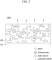
- FIG. 2 illustrates a schematic view representing the progress of drying of electrode slurry in the electrode of FIG. 1 .
- the electrode slurry 120 is coated on the current collector 110 of the electrode 100a, and the electrode slurry 120 includes an electrode active material, a binder, a conductive material and a solvent.
- the binder is in a state of being partially solvated, and flowable in the electrode slurry 120, and is partially vaporized so that it is in a state of being impossible to flow.
- the solvent moves to the surface of the electrode slurry 120 by a capillary phenomenon.
- the binder which is solvated and flowable moves to the surface together with the solvent, the binder is agglomerated.
- the binder after solvent vaporization remains in a state of being agglomerated, and the solvated binder in the electrode slurry 120 continuously moves to the surface by a capillary phenomenon, so that binder agglomeration on the surface further deepens.
- FIG. 3 illustrates a schematic view representing the electrode of FIG. 1 as an XYZ stereotactic coordinate system.
- the electrode slurry 120 is coated on the current collector 110 of the electrode 100, and the electrode slurry 120 includes an electrode active material, a binder, a conductive material and a solvent.
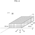
- FIG. 4 illustrates a schematic view representing a method of applying vacuum in a certain direction upon drying the electrode of FIG. 3 according to an exemplary embodiment of the present invention.
- the surface of the electrode slurry 120 refers to the XY plane having the largest Z value (hatched) among them. Since the solvent is vaporized mainly on the surface of the electrode slurry 120, the binder particles moves toward the surface.
- the force to move the binder to the surface of the electrode slurry 120 may be offset or dispersed.
- the vacuum may be applied in optional directions satisfying Z ⁇ 0 (a1, a2 and a3), and the optional directions at Z ⁇ 0 (a1, a2 and a3) refer to opposite directions to the surface of the electrode slurry 120 (hatched), and thus, the movement of the binder may be effectively decreased.
- the vacuum is applied in the side directions b1 and b2
- the force to move the binder to the surface (hatched) of the electrode slurry 120 may be dispersed.
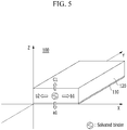
- FIG. 5 illustrates a schematic view representing the force on the solvated binder upon drying the electrode of FIG. 3 according to an exemplary embodiment of the present invention.
- the solvated binder is included in the electrode slurry 120, and for convenience of description, only one binder is illustrated, however, the force acts similarly on the binders positioned in the electrode slurry 120.
- the solvent is vaporized in the surface direction c1 wherein the surface is the upper surface of the electrode slurry 120, and on the solvated binder particles, the force to move them in the surface direction c1 acts by a capillary phenomenon.
- the method of manufacturing an electrode for a rechargeable battery according to the present invention includes a process of drying electrode slurry while applying vacuum in a direction of decreasing agglomeration of the binder due to vaporization of the solvent, thereby decreasing binder agglomeration, improving dispersibility of an electrode active material, and increasing adhesion efficiency of the binder.
- binder agglomeration is decreased, thereby preventing internal resistance increase of an electrode, and improving electrolyte solution impregnability, and thus, the overall performance of a rechargeable battery may be improved.
Landscapes
- Engineering & Computer Science (AREA)
- Chemical & Material Sciences (AREA)
- Manufacturing & Machinery (AREA)
- Chemical Kinetics & Catalysis (AREA)
- Electrochemistry (AREA)
- General Chemical & Material Sciences (AREA)
- Materials Engineering (AREA)
- Battery Electrode And Active Subsutance (AREA)
- Secondary Cells (AREA)
Abstract
Description
- This application claims priority to and the benefit of Korean Patent Application No.
10-2015-0141355 - The present invention relates to a method of manufacturing an electrode for a rechargeable battery including a process of drying electrode slurry by applying vacuum in a certain direction.
- Due to rapid increase of fossil fuel use, demand for use of alternative energy or clean energy is increasing, the field to be most actively studied as part of it is power generation and electricity storage using electrochemistry.
- At present, a representative example of an electrochemical device using this electrochemical energy may include a rechargeable battery, and the usage area thereof is gradually expanding.
- The rechargeable battery is classified into a cylindrical battery and an angular battery in which an electrode assembly is embedded in a cylindrical or angular metal can, and a pouch-shaped battery in which an electrode assembly is embedded in a pouch-shaped case of an aluminum laminate sheet, depending on the shape of a battery case.
- The electrode assembly embedded in the battery case is a repeatedly chargeable and dischargeable power generation device composed of a stacked structure of positive electrode/separator/negative electrode, and classified into a jelly-roll type in which a separator is interposed between a negative electrode and a positive electrode in a long sheet shape having an active material coated thereon and wound, and a stack type in which a plurality of positive and negative electrodes having a predetermined size are sequentially stacked with a separator interposed therebetween.
- As an electrode assembly having a more advanced structure of a mixed form of the jelly-roll type and the stack type, a stack/folding type electrode assembly in which a full cell having a positive electrode/separator/negative electrode structure or a bicell having a positive electrode (negative electrode)/separator/negative electrode (positive electrode)/separator/positive electrode (negative electrode) structure, having a constant unit size is folded using a long continuous separation film, has been developed.
- In addition, in order to improve processability of the conventional stack type electrode assembly, and meet the demand of various types of rechargeable battery, a lamination/stack type electrode assembly having a structure formed by stacking unit cells in which electrodes and separators are stacked alternately and laminated has been also developed.
- Meanwhile, an electrode which is a core constituent element of this rechargeable battery is manufactured by applying electrode slurry including an electrode active material, a binder, a solvent and the like on a current collector composed of metals, and performing drying.
- During a drying process of the electrode slurry, binder particles are agglomerated around the surface of an electrode slurry layer. It is known that this phenomenon occurs, since vaporization of the solvent occurs on the surface of the electrode slurry layer during the drying process, and when the solvent in the inside moves to the vicinity of the surface by a capillary phenomenon, the binder which is solvated so that it is in a state of being flowable in the electrode slurry layer moves together to the vicinity of the surface of the electrode slurry layer.
- When binder particles are agglomerated at the vicinity of the surface of the electrode slurry layer, as a whole of the electrode, dispersibility of the electrode active material and the like is deteriorated, and adhesion efficiency of the binder is lowered,
- Eventually, binder particle agglomeration causes problems such as increased internal resistance of the electrode, deteriorated electrolyte solution impregnability, and overall performance degradation of the rechargeable battery.
- Accordingly, there is a high need for technology to decrease binder agglomeration during the drying process of electrode slurry, thereby capable of improving dispersibility of an electrode active material, and increasing adhesion efficiency of a binder.
- The present invention has been made in an effort to provide a method of manufacturing an electrode for a rechargeable battery including a process of drying electrode slurry by applying vacuum in a certain direction having advantages of solving the problems of the relevant art as described above, and overcoming the technical challenges which have been requested from the past.
- The inventors of the present application repeated in-depth research and various experiments, and as a result, as described below, have found out that in the case that when manufacturing an electrode for a rechargeable battery, a process of drying electrode slurry while applying vacuum in a direction of decreasing binder agglomeration due to vaporization of a solvent is included, binder agglomeration is decreased, thereby improving dispersibility of an electrode active material, and increasing adhesion efficiency of the binder, and completed the present invention.
- Therefore, an exemplary embodiment of the present invention provides a method of manufacturing an electrode for a rechargeable battery includes:
- (a) coating electrode slurry including an electrode active material, a binder, and a solvent on one surface of a sheet-shaped current collector; and
- (b) drying the electrode slurry while applying vacuum in a direction of decreasing agglomeration of the binder due to vaporization of the solvent.
- In a general drying process of electrode slurry, as the solvent is vaporized on the surface of an electrode slurry layer, the solvent moves to the surface of the electrode slurry layer by a capillary phenomenon. Here, a binder which is solvated so that it is flowable moves to the surface together with the solvent, thereby causing agglomeration.
- According to the present invention, the movement of the flowable binder to the surface of the electrode slurry layer may be reduced, by applying vacuum in a direction of decreasing the movement of the binder to the surface direction of the electrode slurry layer. That is, the direction of decreasing agglomeration refers to a direction of decreasing the binder moving to a surface direction of an electrode slurry layer, and being agglomerated with each other.
- As a specific example, in an XYZ stereotactic coordinate system, the current collector is located on an XY plane at Z=0, the electrode slurry is coated on one surface of the current collector, on the XY plane under the condition of Z>0, and vacuum may be applied in one or more directions selected from optional directions satisfying Z<0 and optional directions on the XY plane at Z=0.
- When the electrode slurry is coated on one surface of the current collector to form a constant thickness, on the XY plane under the condition of Z>0, the surface of the electrode slurry layer refers to the XY plane having the largest Z value among them.
- Since the solvent is vaporized mainly on the surface of the electrode slurry layer, binder particles move toward the surface.
- Therefore, when vacuum is applied in one or more directions selected from optional directions satisfying Z < 0 and optional directions on the XY plane at Z=0, it is decreased that the binder moves to the surface of the electrode slurry layer and is agglomerated with each other.
- Specifically, since vacuum may be applied in an optional direction satisfying Z<0, and the optional direction of Z<0 refers to the direction opposite to the surface of the electrode slurry layer, the movement of the binder may be effectively decreased.
- Assuming that the surface of the electrode slurry layer is an upper surface, the direction on the XY plane at Z=0 may be a side direction of the electrode slurry layer. As such, when vacuum is applied in the side direction, the force to move the binder to the surface may be dispersed.
- In addition, vacuum may be applied in both a first direction and a second direction on the XY plane at Z=0 simultaneously, and the first direction may be an opposite direction to the second direction. That is, when vacuum is applied in the side direction of the electrode slurry layer, it may be applied in opposite directions simultaneously, in order to prevent the binder from moving with being biased to one side of both sides of the electrode slurry layer.
- As a specific example, the solvent used in the preparation of the electrode slurry may include, for example, an aprotic organic solvent such as N-methyl-2-pyrrolidinone, propylene carbonate, ethylene carbonate, butylene carbonate, dimethyl carbonate, diethyl carbonate, γ-butyrolactone, 1,2-dimethoxy ethane, tetrahydroxyfuran, 2-methyl tetrahydrofuran, dimethylsulfoxide, 1,3-dioxolane, formamide, dimethylformamide, dioxolane, acetonitrile, nitromethane, formic acid methyl, acetic acidmethyl, phosphoric acid triester, trimethoxy methane, a dioxolane derivative, sulfolane, methyl sulfolane, 1,3-dimethyl-2-imidazolidinone, propylene carbonate derivative, a tetrahydrofuran derivative, ether, methyl pyropionate, and ethyl propionate.
- As a specific example, the vacuum may be a pressure of 0.8 atm or less, specifically, a pressure of 0.01 atm or more and 0.4 atm or less.
- When the vacuum is applied with a pressure more than 0.8 atm, the force on the binder particles is so small that it is difficult to decrease the agglomeration of the binder particles, and when the vacuum is applied with a pressure less than 0.01 atm, the force on the electrode slurry layer is so strong that the entire electrode slurry layer tilts to one side, or the surface is uneven, thereby increasing an appearance inferiority rate.
- As a specific example, the vacuum is maintained at constant pressure, or the pressure may be changed.
- Specifically, the vacuum pressure may be changed, and more specifically, the vacuum pressure may be changed with periodic variability. In the case that the vacuum pressure is changed, the movement of the binder may be effectively controlled, as compared with the case of maintaining constant pressure.
- In addition, in the case that the pressure is changed with periodic variability, the movement of the binder may be more effectively controlled with less energy, and thus, the agglomeration of the binder on the surface may be further decreased.
- As a specific example, the process (b) may be carried out in a drying oven to apply heat. In the case that heat is applied together with vacuum, the slurry may be more rapidly dried, and the time during which the binder can be agglomerated is reduced, thereby decreasing an agglomerated amount also.
- Meanwhile, in the process (b), the electrode slurry coated on the current collector is dried by a continuous process, thereby improving productivity.
- Specifically, in the process (b), the continuous process may be carried out, with the other surface of the current collector on which the electrode slurry is coated being in contact with transfer equipment.
- Here, the transfer equipment is not particularly limited, as long as it may continuously transfer the current collector having the electrode slurry coated thereon, but may be for example, a conveyor belt.
- The conveyor belt may have an at least partially penetrated structure so that the vacuum may be applied to the current collector. The penetrated structure refers to a structure in which fluid may move to upper and lower surfaces through the conveyor belt. Through this penetrated structure, even in the case of applying vacuum to the lower surface of the conveyor belt, sufficient vacuum may be applied to the current collector.
- Specifically, the penetrated structure may be a structure in which through-holes are formed in the conveyor belt. Otherwise, the conveyor belt may be composed of a material having pores through which fluid is movable.
- Meanwhile, the current collector may have a thickness of 4 µm to 20 µm, specifically, 4 µm to 10 µm.
- When the thickness is less than 4 µm, the current collector is so thin that the shape may be deformed upon application of vacuum, and when the thickness is more than 20 µm, the current collector is so thick that in the case of applying vacuum to the lower surface of the current collector, it may be difficult to apply the force by vacuum to the electrode slurry layer coated on the upper surface of the current collector.
- As a specific example, the electrode slurry may further include a conductive material for improving the conductivity of the electrode.
- Another embodiment of the present invention provides an electrode for a rechargeable battery manufactured by the above method.
- Yet another embodiment of the present invention provides an electrode assembly including the electrode, and a rechargeable battery in which the electrode assembly is embedded in a battery case together with an electrolyte solution.
- Hereinafter, other components of the rechargeable battery will be described.
- Positive and negative electrodes are collectively called the electrode. The positive electrode may be manufactured by, for example, coating positive electrode slurry in which a positive electrode active material and a binder are mixed on a positive electrode current collector, and drying it, and if required, a conductive material and a filler may be further added to the positive electrode slurry.
- The positive electrode current collector is not particularly limited as long as it does not cause a chemical change in the battery and has high conductivity, and for example, one selected from the group consisting of stainless steel, aluminum, nickel, titanium, and aluminum or stainless steel of which the surface is treated with carbon, nickel, titanium or silver may be used, and specifically, aluminum may be used. The current collector may have fine protrusions and depressions formed on the surface, thereby increasing adhesiveness of the positive electrode active material, and have various shapes such as a film, a sheet, foil, nets, a porous body, foam and a non-woven fabric body.
- The positive electrode active material may include, for example, a layered compound such as lithium cobalt oxide (LiCoO2) and lithium nickel oxide (LiNiO2) or the compound substituted with one or more transition metals; lithium manganese oxide such as a compound of the chemical formula, Li1+xMn2-xO4 (wherein x is 0 - 0.33), LiMnO3, LiMn2O3 and LiMnO2; lithium copper oxide (Li2CuO2); vanadium oxide such as LiV3O8, LiV3O4, V2O5 and Cu2V2O7; Ni-site type lithium nickel oxide represented by the chemical formula, LiNi1-xMxO2 (wherein M = Co, Mn, Al, Cu, Fe, Mg, B or Ga, and x = 0.01 - 0.3); lithium manganese composite oxide represented by the chemical formula, LiMn2-xMxO2 (wherein M = Co, Ni, Fe, Cr, Zn or Ta, and x = 0.01 - 0.1) or Li2Mn3MO8 (wherein M = Fe, Co, Ni, Cu or Zn); LiMn2O4 in which Li of the chemical formula is partially substituted with an alkaline-earth metal ion; a disulfide compound; Fe2(MoO4)3 and the like, but not limited thereto.
- The conductive material is added generally at 1 to 30 wt%, based on the total weight of a positive electrode mixture including the positive electrode active material. This conductive material is not particularly limited, as long as it does not cause a chemical change in the battery and has conductivity, and for example, carbon blacks such as graphite, carbon black, acetylene black, ketjen black, channel black, furnace black, lamp black and summer black; conductive fiber such as carbon fiber or metal fiber; carbon fluoride, metal powder such as aluminum and nickel powder; conductive whisky such as zinc oxide and potassium titanate; conductive metal oxide such as titanium oxide; a conductive material such as a polyphenylene derivative, and the like may be used.
- The binder included in the positive electrode is a component assisting in binding the active material and the conductive material and the like, and binding for the current collector, and generally added at 1 to 30% by weight, based on the total weight of the mixture including the positive electrode active material. The example of this binder may include polyfluorovinylidene, polyvinylalcohol, carboxymethyl cellulose (CMC), starch, hydroxypropyl cellulose, regenerated cellulose, polyvinylpyrrolidone, tetrafluoroethylene, polyethylene, polypropylene, ethylene-propylene-diene terpolymer (EPDM), sulfonated EPDM, styrene butadiene rubber, fluorine rubber, various copolymers and the like.
- The filler is a component suppressing the expansion of the positive electrode, and optionally used, and is not particularly limited as long as it does not cause chemical changes in the battery and is a fibrous material, and for example, olefin-based polymers such as polyethylene and polypropylene; fibrous materials such as glass fiber and carbon fiber, may be used.
- However, the negative electrode may be manufactured by coating negative electrode slurry including a negative electrode active material and a binder on the negative electrode current collector, and a dispersing agent, a filler and the like may be optionally further included.
- The negative electrode current collector is not particularly limited as long as it does not cause a chemical change in the battery and has conductivity, and for example, copper, stainless steel, aluminum, nickel, titanium, sintered carbon, copper or stainless steel of which the surface is treated with carbon, nickel, titanium, silver and the like, an aluminum-cadmium alloy and the like may be used. Further, like the positive electrode current collector, the binding force of the negative electrode active material may be strengthened by forming fine protrusions and depressions on the surface thereof, and the negative electrode current collector may be used in various shapes such as a film, a sheet, a foil, nets, a porous body, foam and a non-woven fabric body.
- The negative electrode active material may include, for example, natural graphite, artificial graphite, metal composite oxides such as LixFe2O3 (0≤x≤1), LixWO2 (0≤x≤1) and SnxMe1-xMe'yOz (Me: Mn, Fe, Pb, Ge; Me': Al, B, P, Si, Group 1, 2 and 3 elements of the periodic table, halogen; 0≤x≤1; 1≤y≤3; 1≤z≤8); lithium metal; lithium alloy; silicon-based alloy; tin-based alloy; metal oxides such as SnO, SnO2, PbO, PbO2, Pb2O3, Pb3O4, Sb2O3, Sb2O4, Sb2O5, GeO, GeO2, Bi2O3, Bi2O4 and Bi2O5; a conductive polymer such as polyacetylene; Li-Co-Ni-based material, and the like.
- As a specific example, the separator may be a polyolefin-based film commonly used in the art, and for example, a sheet composed of one or more selected from the group consisting of high density polyethylene, low density polyethylene, linear low density polyethylene, ultrahigh molecular weight polyethylene, polypropylene, polyethylene terephthalate, polybutylene terephthalate, polyester, polyacetal, polyamide, polycarbonate, polyimide, polyetheretherketone, polyethersulfone, polyphenylene oxide, polyphenylene sulfide, polyethylene naphthalene and a mixture thereof.
- The separator may be composed of identical materials to each other, but not limited thereto, and of course, may be composed of different materials from each other, depending on the safety, energy density and overall performance of the battery cell.
- The pore size and porosity of the separator are not particularly limited, but the porosity may be in a range of 10 to 95%, and the pore size (diameter) may be 0.1 to 50 µm. In the case that the pore size and the porosity are less than 0.1 µm and 10%, respectively, the separator serves as a resistance layer, and in the case that the pore size and the porosity are more than 50 µm and 95%, it is difficult to maintain mechanical properties.
- The electrolyte solution may be a lithium salt-containing non-aqueous electrolyte, the lithium salt-containing non-aqueous electrolyte is composed of a non-aqueous electrolyte and a lithium salt, and the non-aqueous electrolyte may include a non-aqueous organic solvent, an organic solid electrolyte, an inorganic solid electrolyte and the like, but not limited thereto.
- The non-aqueous organic solvent may include, for example, aprotic organic solvents such as N-methyl-2-pyrrolidinone, propylene carbonate, ethylene carbonate, butylene carbonate, dimethyl carbonate, diethyl carbonate, γ-butyrolactone, 1,2-dimethoxy ethane, tetrahydroxyfuran, 2-methyl tetrahydrofuran, dimethylsulfoxide, 1,3-dioxolane, formamide, dimethylformamide, dioxolane, acetonitrile, nitromethane, methyl formate, acetic acidmethyl, phosphoric acid triester, trimethoxy methane, a dioxolane derivative, sulfolane, methyl sulfolane, 1,3-dimethyl-2-imidazolidinone, a propylene carbonate derivative, a tetrahydrofuran derivative, ether, methyl propionate, ethyl propionate and the like.
- The organic solid electrolyte may include, for example, a polyethylene derivative, a polyethylene oxide derivative, a polypropylene oxide derivative, a phosphoric acid ester polymer, poly agitation lysine, polyester sulfide, polyvinyl alcohol, polyvinylidene fluoride, a polymer including an ionic dissociation group, and the like.
- The inorganic solid electrolyte may include, for example, nitride, halide and sulfate of Li such as Li3N, Lil, Li5NI2, Li3N-Lil-LiOH, LiSiO4, LiSiO4-Lil-LiOH, Li2SiS3, Li4SiO4, Li4SiO4-Lil-LiOH, and Li3PO4-Li2S-SiS2, and the like.
- The lithium salt is a material which is readily dissolved in the non-aqueous electrolyte, and may include, for example, LiCI, LiBr, Lil, LiClO4, LiBF4, LiB10Cl10, LiPF6, LiCF3SO3, LiCF3CO2, LiAsF6, LiSbF6, LiAlCl4, CH3SO3Li, (CF3SO2)2NLi, lithium chloroborane, lower aliphatic lithium carbonate, 4-phenyl lithium borate, imide and the like.
- In addition, to the non-aqueous electrolyte, for improving charge and discharge characteristic, flame retardant and the like, for example, pyridine, triethyl phosphite, triethanolamine, cyclic ether, ethylene diamine, n-glyme, triamide hexaphosphate, a nitrobenzene derivative, sulfur, a quinone imine dye, N-substituted oxazolidinone, N,N-substituted imidazolidine, ethylene glycol dialkyl ether, an ammonium salt, pyrrole, 2-methoxy ethanol, aluminum trichloride and the like may be added.
- In some cases, for imparting inflammability, a halogen-containing solvent such as carbon tetrachloride and ethylene trifluoride may be further included, and for improving high temperature storage characteristics, carbon dioxide gas may be further included, and FEC (fluoro-ethylene carbonate), PRS (propene sultone) and the like may be further included.
- As a specific example, a lithium salt such as LiPF6, LiClO4, LiBF4, and LiN (SO2CF3)2 is added to a mixed solvent of cyclic carbonate such as EC or PC which is a high dielectric solvent and linear carbonate such as DEC, DMC or EMC which is a low viscosity solvent, thereby preparing the lithium salt-containing non-aqueous electrolyte.
- Yet another embodiment of the present invention provides a battery pack including this rechargeable battery as a unit cell, and a device including this battery pack as a power supply.
- The device may be, for example, a laptop computer, a netbook, a tablet PC, a mobile phone, MP3, a wearable electronic device, a power tool, an electric vehicle (EV), a hybrid electric vehicle (HEV), a plug-in hybrid electric vehicle (PHEV), an electric bicycle (E-bike), an electric scooter (E-scooter), an electric golf cart, or a system for electric power storage, but of course, not limited thereto.
- Since the structure and manufacturing method of this device are known in the art, the details therefor will be omitted in the present specification.
-
-
FIG. 1 is a schematic view of an electrode having electrode slurry coated on a current collector; -
FIG. 2 is a schematic view representing the progress of drying of electrode slurry in the electrode ofFIG. 1 ; -
FIG. 3 is a schematic view representing the electrode ofFIG. 1 as an XYZ stereotactic coordinate system; -
FIG. 4 is a schematic view illustrating a method of applying vacuum in a certain direction upon drying the electrode ofFIG. 3 according to an exemplary embodiment of the present invention; and -
FIG. 5 is a schematic view representing force on a solvated binder upon drying the electrode ofFIG. 3 according to an exemplary embodiment of the present invention. - Hereinafter, the present invention will be described referring to drawings according to an exemplary embodiment of the present invention, but this is for easier understanding of the present invention, and the scope of the present invention is not limited thereto.
-
FIG. 1 illustrates a schematic view of an electrode having electrode slurry coated on a current collector. - Referring to
FIG. 1 ,electrode slurry 120 is coated on acurrent collector 110 of anelectrode 100, theelectrode slurry 120 includes an electrode active material, a binder, a conductive material and a solvent, and in particular the binder is in a state of being solvated, and flowable in theelectrode slurry 120. - Immediately after coating the
electrode slurry 120 on thecurrent collector 110, the electrode active material, binder and conductive material are dispersed overall uniformly in theelectrode slurry 120. -
FIG. 2 illustrates a schematic view representing the progress of drying of electrode slurry in the electrode ofFIG. 1 . - Referring to
FIG. 2 , theelectrode slurry 120 is coated on thecurrent collector 110 of theelectrode 100a, and theelectrode slurry 120 includes an electrode active material, a binder, a conductive material and a solvent. The binder is in a state of being partially solvated, and flowable in theelectrode slurry 120, and is partially vaporized so that it is in a state of being impossible to flow. - Specifically, as the solvent is vaporized on the surface of the
electrode slurry 120, the solvent moves to the surface of theelectrode slurry 120 by a capillary phenomenon. Here, as a binder which is solvated and flowable moves to the surface together with the solvent, the binder is agglomerated. - On the surface of the
electrode slurry 120, the binder after solvent vaporization remains in a state of being agglomerated, and the solvated binder in theelectrode slurry 120 continuously moves to the surface by a capillary phenomenon, so that binder agglomeration on the surface further deepens. -
FIG. 3 illustrates a schematic view representing the electrode ofFIG. 1 as an XYZ stereotactic coordinate system. - Referring to
FIG. 3 together withFIG. 1 , theelectrode slurry 120 is coated on thecurrent collector 110 of theelectrode 100, and theelectrode slurry 120 includes an electrode active material, a binder, a conductive material and a solvent. - Specifically, in an XYZ stereotactic coordinate system, the
current collector 110 is located on an XY plane at Z=0, and theelectrode slurry 120 is coated on one surface of thecurrent collector 110, on the XY plane under the condition of Z>0. -
FIG. 4 illustrates a schematic view representing a method of applying vacuum in a certain direction upon drying the electrode ofFIG. 3 according to an exemplary embodiment of the present invention. - Referring to
FIG. 4 , when theelectrode slurry 120 is coated on one surface of thecurrent collector 110 in a constant thickness formed, on the XY plane under the condition of Z>0, the surface of theelectrode slurry 120 refers to the XY plane having the largest Z value (hatched) among them. Since the solvent is vaporized mainly on the surface of theelectrode slurry 120, the binder particles moves toward the surface. - Therefore, when applying vacuum in one or more directions selected from optional directions satisfying Z<0 (a1, a2 and a3), and optional directions on the XY plane at Z=0 (b1 and b2), the force to move the binder to the surface of the
electrode slurry 120 may be offset or dispersed. - Specifically, the vacuum may be applied in optional directions satisfying Z<0 (a1, a2 and a3), and the optional directions at Z<0 (a1, a2 and a3) refer to opposite directions to the surface of the electrode slurry 120 (hatched), and thus, the movement of the binder may be effectively decreased.
- Assuming that the surface of the electrode slurry 120 (hatched) is an upper surface, the directions on the XY plane at Z=0 (b1 and b2) may be a side (plaid) direction of the
electrode slurry 120. As such, when the vacuum is applied in the side directions b1 and b2, the force to move the binder to the surface (hatched) of theelectrode slurry 120 may be dispersed. - The vacuum may be applied in a first direction b1 and a second direction b2 simultaneously on the XY plane at Z=0, and the first direction b1 is opposite to the second direction b2. That is, when the vacuum is applied in the side direction of the
electrode slurry 120, the vacuum may be applied at opposite directions simultaneously in order to prevent the binder from moving with being biased to one side of both sides of theelectrode slurry layer 120. -
FIG. 5 illustrates a schematic view representing the force on the solvated binder upon drying the electrode ofFIG. 3 according to an exemplary embodiment of the present invention. - Referring to
FIG. 5 , the solvated binder is included in theelectrode slurry 120, and for convenience of description, only one binder is illustrated, however, the force acts similarly on the binders positioned in theelectrode slurry 120. - The solvent is vaporized in the surface direction c1 wherein the surface is the upper surface of the
electrode slurry 120, and on the solvated binder particles, the force to move them in the surface direction c1 acts by a capillary phenomenon. - Here, when the vacuum is applied in the lower surface direction a1 satisfying Z<0 of the
electrode slurry 120, suction by the vacuum acts in an opposite direction to the force acting in the surface direction c1, and thus, the force to move the binder to the surface direction c1 is offset. - Further, the vacuum is applied in opposite directions, the first direction b1 and the second direction b2 on the XY plane at Z=0 simultaneously, thereby dispersing the force to move the solvated binder to the surface c1 of the
electrode slurry 120, and at the same time, preventing the solvated binder from moving with being biased to one side of both sides of theelectrode slurry 120. - As described above, the present invention has been described referring to the drawings according to an exemplary embodiment of the present invention, however, it is possible for a person with ordinary skill in the art to which the present invention pertains to perform various applications and modification within the scope of the present invention, based on the description above.
- As described above, the method of manufacturing an electrode for a rechargeable battery according to the present invention includes a process of drying electrode slurry while applying vacuum in a direction of decreasing agglomeration of the binder due to vaporization of the solvent, thereby decreasing binder agglomeration, improving dispersibility of an electrode active material, and increasing adhesion efficiency of the binder.
- Further, binder agglomeration is decreased, thereby preventing internal resistance increase of an electrode, and improving electrolyte solution impregnability, and thus, the overall performance of a rechargeable battery may be improved.
Claims (21)
- A method of manufacturing an electrode for a rechargeable battery, comprising:(a) coating electrode slurry including an electrode active material, a binder, and a solvent on one surface of a sheet-shaped current collector; and(b) drying the electrode slurry while applying vacuum in a direction of decreasing agglomeration of the binder due to vaporization of the solvent.
- The method of claim 1, wherein in an XYZ stereotactic coordinate system,
the current collector is located on an XY plane at Z=0,
the electrode slurry is coated on one surface of the current collector, on the XY plane under a condition of Z>0, and
the vacuum is applied in one or more directions selected from optional directions satisfying Z<0 and optional directions on the XY plane at Z=0. - The method of claim 2, wherein the vacuum is applied in the optional direction satisfying Z<0.
- The method of claim 2, wherein the vacuum is applied in a first direction and a second direction on the XY pane at Z=0 simultaneously, and the first direction is opposite to the second direction.
- The method of claim 1, wherein the vacuum is a pressure of 0.8 atm or less.
- The method of claim 1, wherein the vacuum is a pressure of 0.01 atm or more and 0.4 atm or less.
- The method of claim 1, wherein the vacuum is maintained at constant pressure, or the pressure is changed.
- The method of claim 1, wherein the vacuum pressure is changed with periodic variability.
- The method of claim 1, wherein the process (b) is carried out in a drying oven to apply heat.
- The method of claim 1, wherein in the process (b), the electrode slurry coated on the current collector is dried by a continuous process.
- The method of claim 10, wherein in the process (b), the continuous process is carried out with the other surface of the current collector on which the electrode slurry is coated being in contact with transfer equipment.
- The method of claim 11, wherein the transfer equipment is a conveyor belt.
- The method of claim 12, wherein the conveyor belt is at least partially composed of a penetrated structure so that the vacuum is applied to the current collector.
- The method of claim 1, wherein the current collector has a thickness of 4 µm to 20 µm.
- The method of claim 1, wherein the current collector has a thickness of 4 µm to 10 µm.
- The method of claim 1, wherein the electrode slurry further includes a conductive material.
- An electrode for a rechargeable battery, manufactured by the method of claim 1.
- An electrode assembly comprising the electrode of claim 17.
- A rechargeable battery comprising the electrode assembly of claim 18, wherein the electrode assembly is embedded in a battery case together with an electrolyte solution.
- A battery pack comprising the rechargeable battery of claim 19 as a unit cell.
- A device comprising the battery pack of claim 20 as a power supply.
Applications Claiming Priority (2)
| Application Number | Priority Date | Filing Date | Title |
|---|---|---|---|
| KR1020150141355A KR102003704B1 (en) | 2015-10-08 | 2015-10-08 | Method of Manufacturing Electrode for Secondary Battery Comprising Step of Drying Electrode Slurry by Applying Vacuum at Specified Direction |
| PCT/KR2016/010289 WO2017061714A1 (en) | 2015-10-08 | 2016-09-12 | Method for manufacturing electrode for secondary battery, comprising process of drying electrode slurry by applying vacuum in specific direction |
Publications (3)
| Publication Number | Publication Date |
|---|---|
| EP3312910A1 true EP3312910A1 (en) | 2018-04-25 |
| EP3312910A4 EP3312910A4 (en) | 2018-04-25 |
| EP3312910B1 EP3312910B1 (en) | 2020-08-05 |
Family
ID=58487976
Family Applications (1)
| Application Number | Title | Priority Date | Filing Date |
|---|---|---|---|
| EP16853830.4A Active EP3312910B1 (en) | 2015-10-08 | 2016-09-12 | Method for manufacturing electrode for secondary battery, comprising process of drying electrode slurry by applying vacuum in specific direction |
Country Status (6)
| Country | Link |
|---|---|
| US (1) | US10581059B2 (en) |
| EP (1) | EP3312910B1 (en) |
| JP (1) | JP2018521480A (en) |
| KR (1) | KR102003704B1 (en) |
| CN (1) | CN107925050B (en) |
| WO (1) | WO2017061714A1 (en) |
Cited By (1)
| Publication number | Priority date | Publication date | Assignee | Title |
|---|---|---|---|---|
| FR3072506A1 (en) * | 2017-10-17 | 2019-04-19 | Commissariat A L'energie Atomique Et Aux Energies Alternatives | PROCESS FOR THE CONTINUOUS PRODUCTION OF AN ELECTRODE |
Family Cites Families (26)
| Publication number | Priority date | Publication date | Assignee | Title |
|---|---|---|---|---|
| JPH07220722A (en) * | 1994-01-28 | 1995-08-18 | Sumitomo Chem Co Ltd | Method for manufacturing electrode for lithium secondary battery |
| JPH07305956A (en) * | 1994-05-11 | 1995-11-21 | Sanwa Jushi Sangyo Kk | Pasted sheet drying furnace |
| JP3299429B2 (en) * | 1995-12-13 | 2002-07-08 | 松下電器産業株式会社 | Battery electrode drying equipment |
| US6692873B1 (en) | 1999-08-05 | 2004-02-17 | Skc Co., Ltd. | Composition for forming electrode active material of lithium secondary battery, composition for forming separator and method of preparing lithium secondary battery using the compositions |
| DE60143666D1 (en) | 2000-10-05 | 2011-01-27 | Panasonic Corp | FLAT BATTERY AND MANUFACTURING METHOD THEREFOR |
| JP4996822B2 (en) * | 2004-11-10 | 2012-08-08 | 本田技研工業株式会社 | Manufacturing method of electrode layer for fuel cell |
| KR100659863B1 (en) | 2005-11-30 | 2006-12-19 | 삼성에스디아이 주식회사 | Electrode Formation Method of Secondary Battery |
| JP2010033918A (en) | 2008-07-30 | 2010-02-12 | Idemitsu Kosan Co Ltd | Manufacturing method of lithium battery, and lithium battery obtained by the same |
| RU2500560C2 (en) * | 2009-04-16 | 2013-12-10 | К Текнолоджи АБ | Freight car and method of its loading |
| CN102246333A (en) * | 2009-09-18 | 2011-11-16 | 松下电器产业株式会社 | Electrode for non-aqueous electrolyte secondary cell, method for producing same, and non-aqueous electrolyte secondary cell |
| US8574763B2 (en) * | 2010-10-13 | 2013-11-05 | Toyota Jidosha Kabushiki Kaisha | Electrode plate with a binder in a surface section with a lower glass transition point than a binder in a current collector plate section, secondary battery, and method for producing the electrode plate |
| US9673453B2 (en) * | 2010-12-06 | 2017-06-06 | Toyota Jidosha Kabushiki Kaisha | Method for manufacturing lithium ion secondary battery |
| JP2012212873A (en) | 2011-03-24 | 2012-11-01 | Tokyo Electron Ltd | Electrode manufacturing device, electrode manufacturing method, program and computer storage medium |
| JP2012251763A (en) * | 2011-05-12 | 2012-12-20 | Sharp Corp | Apparatus and method for drying electrode |
| CN103947021B (en) | 2011-08-02 | 2018-02-09 | 普列托电池公司 | A kind of lithium ion battery with IPN electrode |
| JP5831223B2 (en) * | 2011-12-28 | 2015-12-09 | 日産自動車株式会社 | Electrode drying method, electrode drying control method, electrode drying apparatus, and electrode drying control apparatus |
| JP2015509269A (en) | 2012-01-17 | 2015-03-26 | バラスト エナジー インコーポレイテッド | Electrodes and batteries |
| WO2013146916A1 (en) * | 2012-03-28 | 2013-10-03 | 日本ゼオン株式会社 | Electrode for all-solid-state secondary batteries and method for producing same |
| KR20130130292A (en) | 2012-05-22 | 2013-12-02 | 주식회사 엘지화학 | Method for drying electrode and secondary battery manufactured using the same |
| US10276857B2 (en) * | 2012-09-25 | 2019-04-30 | Toyota Jidosha Kabushiki Kaisha | Method of manufacturing electrode for secondary battery and hot-gas drying furnace |
| KR20140054840A (en) | 2012-10-30 | 2014-05-09 | 주식회사 엘지화학 | Electrode drying device |
| KR102007697B1 (en) | 2013-02-28 | 2019-08-06 | 삼성에스디아이 주식회사 | Electrode fabricating appratus for rechargeable battery |
| EP3043407B1 (en) | 2013-11-18 | 2020-04-22 | LG Chem, Ltd. | Positive electrode active material for lithium secondary battery having surface treated using fluoropolymer and manufacturing method therefor |
| JP2015173034A (en) * | 2014-03-11 | 2015-10-01 | トヨタ自動車株式会社 | Method and apparatus for producing electrode for non-aqueous electrolyte secondary battery |
| JP6126546B2 (en) | 2014-03-26 | 2017-05-10 | 株式会社日立製作所 | Method and apparatus for producing negative electrode for lithium ion secondary battery |
| DE102015015777A1 (en) | 2015-01-20 | 2016-07-21 | Mann + Hummel Gmbh | Filter medium and filter element with a filter medium |
-
2015
- 2015-10-08 KR KR1020150141355A patent/KR102003704B1/en active Active
-
2016
- 2016-09-12 JP JP2018502104A patent/JP2018521480A/en active Pending
- 2016-09-12 CN CN201680046774.5A patent/CN107925050B/en active Active
- 2016-09-12 WO PCT/KR2016/010289 patent/WO2017061714A1/en not_active Ceased
- 2016-09-12 EP EP16853830.4A patent/EP3312910B1/en active Active
- 2016-09-12 US US15/744,563 patent/US10581059B2/en active Active
Cited By (2)
| Publication number | Priority date | Publication date | Assignee | Title |
|---|---|---|---|---|
| FR3072506A1 (en) * | 2017-10-17 | 2019-04-19 | Commissariat A L'energie Atomique Et Aux Energies Alternatives | PROCESS FOR THE CONTINUOUS PRODUCTION OF AN ELECTRODE |
| EP3474349A1 (en) * | 2017-10-17 | 2019-04-24 | Commissariat à l'énergie atomique et aux énergies alternatives | Method for the continuous production of an electrode |
Also Published As
| Publication number | Publication date |
|---|---|
| EP3312910A4 (en) | 2018-04-25 |
| CN107925050B (en) | 2020-12-04 |
| US10581059B2 (en) | 2020-03-03 |
| US20180205066A1 (en) | 2018-07-19 |
| WO2017061714A1 (en) | 2017-04-13 |
| KR20170041995A (en) | 2017-04-18 |
| JP2018521480A (en) | 2018-08-02 |
| CN107925050A (en) | 2018-04-17 |
| EP3312910B1 (en) | 2020-08-05 |
| KR102003704B1 (en) | 2019-07-25 |
Similar Documents
| Publication | Publication Date | Title |
|---|---|---|
| EP2378595A2 (en) | High-power lithium secondary battery | |
| KR102005779B1 (en) | Method of Manufacturing Negative Electrode for Secondary Battery Comprising Active Material Layers Having Different Particle Shape of Negative Active Material | |
| KR101643593B1 (en) | Stack and Folding-Typed Electrode Assembly Having Improved Electrolyte Wetting Property and Method of Preparation of the Same | |
| KR102071489B1 (en) | Electrode Comprising Active Material Layers Having Active Material Particles of Different Average Particle Sizes | |
| KR102079929B1 (en) | Manufacturing Method for Electrodes Having Uniform Quality and Manufacturing Method for Electrode Assembly with the Same | |
| KR101822992B1 (en) | Multilayer Electrode for Secondary Battery and Preparation Method Thereof | |
| CN103765653B (en) | Secondary battery with excellent productivity and safety | |
| KR101884247B1 (en) | Preparation Method of Multilayer Electrode for Secondary Battery | |
| KR101717220B1 (en) | Electrode for Secondary Battery Having Current Collector | |
| KR102011679B1 (en) | Electrode Assembly Comprising Electrode Plate Having Different Loading Amounts of Active Material on both Sides | |
| CN104584305A (en) | Method for manufacturing secondary battery | |
| KR102026292B1 (en) | Electrode Assembly Comprising Electrode Having Gradient in Loading Amount of Active Material | |
| KR20180097243A (en) | Method for Preparation of Electrode Assembly Comprising Step of Assigning Electrode Plates | |
| KR101995292B1 (en) | Method of Manufacturing Electrode Plate Using Electrode Sheet Including Notching Part at Center | |
| KR20170031375A (en) | Negative Electrode Comprising Active Material Layers Having Different Binder Contents | |
| KR102000539B1 (en) | Method of Manufacturing Electrode Plate Using Unit Electrode Sheet Including Coating Portions Having Different Size from One Another | |
| KR102096821B1 (en) | Method of Manufacturing Negative Electrode for Secondary Battery Comprising Active Material Layers Having Different Hardness of Negative Active Material | |
| KR102094483B1 (en) | Positive Electrode Mix for Secondary Battery Comprising Conductive Materials of Different Shapes | |
| KR102082467B1 (en) | Electrode Assembly Comprising Electrode Having High Loading Amount of Active Material at Middle of Current Collector | |
| EP3370281B1 (en) | Electrode including electrode current collector with three-dimensional network structure | |
| CN104137320B (en) | Lithium secondary battery with excellent performance | |
| KR102025564B1 (en) | Electrode Assembly Comprising Unit Cell Sandwiched between Battery Elements | |
| EP3312910B1 (en) | Method for manufacturing electrode for secondary battery, comprising process of drying electrode slurry by applying vacuum in specific direction | |
| CN103918119B (en) | Secondary battery with excellent productivity and safety | |
| KR20180081228A (en) | Electrode Assembly Comprising Electrode Having Different Porosity Depending on Position of Unit-cell |
Legal Events
| Date | Code | Title | Description |
|---|---|---|---|
| STAA | Information on the status of an ep patent application or granted ep patent |
Free format text: STATUS: THE INTERNATIONAL PUBLICATION HAS BEEN MADE |
|
| PUAI | Public reference made under article 153(3) epc to a published international application that has entered the european phase |
Free format text: ORIGINAL CODE: 0009012 |
|
| STAA | Information on the status of an ep patent application or granted ep patent |
Free format text: STATUS: REQUEST FOR EXAMINATION WAS MADE |
|
| 17P | Request for examination filed |
Effective date: 20180117 |
|
| A4 | Supplementary search report drawn up and despatched |
Effective date: 20180321 |
|
| AK | Designated contracting states |
Kind code of ref document: A1 Designated state(s): AL AT BE BG CH CY CZ DE DK EE ES FI FR GB GR HR HU IE IS IT LI LT LU LV MC MK MT NL NO PL PT RO RS SE SI SK SM TR |
|
| AX | Request for extension of the european patent |
Extension state: BA ME |
|
| DAV | Request for validation of the european patent (deleted) | ||
| DAX | Request for extension of the european patent (deleted) | ||
| STAA | Information on the status of an ep patent application or granted ep patent |
Free format text: STATUS: EXAMINATION IS IN PROGRESS |
|
| 17Q | First examination report despatched |
Effective date: 20190916 |
|
| GRAP | Despatch of communication of intention to grant a patent |
Free format text: ORIGINAL CODE: EPIDOSNIGR1 |
|
| STAA | Information on the status of an ep patent application or granted ep patent |
Free format text: STATUS: GRANT OF PATENT IS INTENDED |
|
| INTG | Intention to grant announced |
Effective date: 20200507 |
|
| GRAS | Grant fee paid |
Free format text: ORIGINAL CODE: EPIDOSNIGR3 |
|
| GRAA | (expected) grant |
Free format text: ORIGINAL CODE: 0009210 |
|
| STAA | Information on the status of an ep patent application or granted ep patent |
Free format text: STATUS: THE PATENT HAS BEEN GRANTED |
|
| AK | Designated contracting states |
Kind code of ref document: B1 Designated state(s): AL AT BE BG CH CY CZ DE DK EE ES FI FR GB GR HR HU IE IS IT LI LT LU LV MC MK MT NL NO PL PT RO RS SE SI SK SM TR |
|
| REG | Reference to a national code |
Ref country code: GB Ref legal event code: FG4D |
|
| REG | Reference to a national code |
Ref country code: CH Ref legal event code: EP |
|
| REG | Reference to a national code |
Ref country code: AT Ref legal event code: REF Ref document number: 1299984 Country of ref document: AT Kind code of ref document: T Effective date: 20200815 |
|
| REG | Reference to a national code |
Ref country code: DE Ref legal event code: R096 Ref document number: 602016041610 Country of ref document: DE |
|
| REG | Reference to a national code |
Ref country code: IE Ref legal event code: FG4D |
|
| REG | Reference to a national code |
Ref country code: LT Ref legal event code: MG4D |
|
| REG | Reference to a national code |
Ref country code: NL Ref legal event code: MP Effective date: 20200805 |
|
| REG | Reference to a national code |
Ref country code: AT Ref legal event code: MK05 Ref document number: 1299984 Country of ref document: AT Kind code of ref document: T Effective date: 20200805 |
|
| PG25 | Lapsed in a contracting state [announced via postgrant information from national office to epo] |
Ref country code: GR Free format text: LAPSE BECAUSE OF FAILURE TO SUBMIT A TRANSLATION OF THE DESCRIPTION OR TO PAY THE FEE WITHIN THE PRESCRIBED TIME-LIMIT Effective date: 20201106 Ref country code: NO Free format text: LAPSE BECAUSE OF FAILURE TO SUBMIT A TRANSLATION OF THE DESCRIPTION OR TO PAY THE FEE WITHIN THE PRESCRIBED TIME-LIMIT Effective date: 20201105 Ref country code: FI Free format text: LAPSE BECAUSE OF FAILURE TO SUBMIT A TRANSLATION OF THE DESCRIPTION OR TO PAY THE FEE WITHIN THE PRESCRIBED TIME-LIMIT Effective date: 20200805 Ref country code: AT Free format text: LAPSE BECAUSE OF FAILURE TO SUBMIT A TRANSLATION OF THE DESCRIPTION OR TO PAY THE FEE WITHIN THE PRESCRIBED TIME-LIMIT Effective date: 20200805 Ref country code: SE Free format text: LAPSE BECAUSE OF FAILURE TO SUBMIT A TRANSLATION OF THE DESCRIPTION OR TO PAY THE FEE WITHIN THE PRESCRIBED TIME-LIMIT Effective date: 20200805 Ref country code: HR Free format text: LAPSE BECAUSE OF FAILURE TO SUBMIT A TRANSLATION OF THE DESCRIPTION OR TO PAY THE FEE WITHIN THE PRESCRIBED TIME-LIMIT Effective date: 20200805 Ref country code: BG Free format text: LAPSE BECAUSE OF FAILURE TO SUBMIT A TRANSLATION OF THE DESCRIPTION OR TO PAY THE FEE WITHIN THE PRESCRIBED TIME-LIMIT Effective date: 20201105 Ref country code: PT Free format text: LAPSE BECAUSE OF FAILURE TO SUBMIT A TRANSLATION OF THE DESCRIPTION OR TO PAY THE FEE WITHIN THE PRESCRIBED TIME-LIMIT Effective date: 20201207 Ref country code: LT Free format text: LAPSE BECAUSE OF FAILURE TO SUBMIT A TRANSLATION OF THE DESCRIPTION OR TO PAY THE FEE WITHIN THE PRESCRIBED TIME-LIMIT Effective date: 20200805 Ref country code: ES Free format text: LAPSE BECAUSE OF FAILURE TO SUBMIT A TRANSLATION OF THE DESCRIPTION OR TO PAY THE FEE WITHIN THE PRESCRIBED TIME-LIMIT Effective date: 20200805 |
|
| PG25 | Lapsed in a contracting state [announced via postgrant information from national office to epo] |
Ref country code: PL Free format text: LAPSE BECAUSE OF FAILURE TO SUBMIT A TRANSLATION OF THE DESCRIPTION OR TO PAY THE FEE WITHIN THE PRESCRIBED TIME-LIMIT Effective date: 20200805 Ref country code: LV Free format text: LAPSE BECAUSE OF FAILURE TO SUBMIT A TRANSLATION OF THE DESCRIPTION OR TO PAY THE FEE WITHIN THE PRESCRIBED TIME-LIMIT Effective date: 20200805 Ref country code: NL Free format text: LAPSE BECAUSE OF FAILURE TO SUBMIT A TRANSLATION OF THE DESCRIPTION OR TO PAY THE FEE WITHIN THE PRESCRIBED TIME-LIMIT Effective date: 20200805 Ref country code: RS Free format text: LAPSE BECAUSE OF FAILURE TO SUBMIT A TRANSLATION OF THE DESCRIPTION OR TO PAY THE FEE WITHIN THE PRESCRIBED TIME-LIMIT Effective date: 20200805 Ref country code: IS Free format text: LAPSE BECAUSE OF FAILURE TO SUBMIT A TRANSLATION OF THE DESCRIPTION OR TO PAY THE FEE WITHIN THE PRESCRIBED TIME-LIMIT Effective date: 20201205 |
|
| PG25 | Lapsed in a contracting state [announced via postgrant information from national office to epo] |
Ref country code: EE Free format text: LAPSE BECAUSE OF FAILURE TO SUBMIT A TRANSLATION OF THE DESCRIPTION OR TO PAY THE FEE WITHIN THE PRESCRIBED TIME-LIMIT Effective date: 20200805 Ref country code: SM Free format text: LAPSE BECAUSE OF FAILURE TO SUBMIT A TRANSLATION OF THE DESCRIPTION OR TO PAY THE FEE WITHIN THE PRESCRIBED TIME-LIMIT Effective date: 20200805 Ref country code: RO Free format text: LAPSE BECAUSE OF FAILURE TO SUBMIT A TRANSLATION OF THE DESCRIPTION OR TO PAY THE FEE WITHIN THE PRESCRIBED TIME-LIMIT Effective date: 20200805 Ref country code: DK Free format text: LAPSE BECAUSE OF FAILURE TO SUBMIT A TRANSLATION OF THE DESCRIPTION OR TO PAY THE FEE WITHIN THE PRESCRIBED TIME-LIMIT Effective date: 20200805 Ref country code: CZ Free format text: LAPSE BECAUSE OF FAILURE TO SUBMIT A TRANSLATION OF THE DESCRIPTION OR TO PAY THE FEE WITHIN THE PRESCRIBED TIME-LIMIT Effective date: 20200805 |
|
| REG | Reference to a national code |
Ref country code: CH Ref legal event code: PL |
|
| REG | Reference to a national code |
Ref country code: DE Ref legal event code: R097 Ref document number: 602016041610 Country of ref document: DE |
|
| PG25 | Lapsed in a contracting state [announced via postgrant information from national office to epo] |
Ref country code: AL Free format text: LAPSE BECAUSE OF FAILURE TO SUBMIT A TRANSLATION OF THE DESCRIPTION OR TO PAY THE FEE WITHIN THE PRESCRIBED TIME-LIMIT Effective date: 20200805 Ref country code: MC Free format text: LAPSE BECAUSE OF FAILURE TO SUBMIT A TRANSLATION OF THE DESCRIPTION OR TO PAY THE FEE WITHIN THE PRESCRIBED TIME-LIMIT Effective date: 20200805 |
|
| PLBE | No opposition filed within time limit |
Free format text: ORIGINAL CODE: 0009261 |
|
| STAA | Information on the status of an ep patent application or granted ep patent |
Free format text: STATUS: NO OPPOSITION FILED WITHIN TIME LIMIT |
|
| REG | Reference to a national code |
Ref country code: BE Ref legal event code: MM Effective date: 20200930 |
|
| PG25 | Lapsed in a contracting state [announced via postgrant information from national office to epo] |
Ref country code: LU Free format text: LAPSE BECAUSE OF NON-PAYMENT OF DUE FEES Effective date: 20200912 Ref country code: SK Free format text: LAPSE BECAUSE OF FAILURE TO SUBMIT A TRANSLATION OF THE DESCRIPTION OR TO PAY THE FEE WITHIN THE PRESCRIBED TIME-LIMIT Effective date: 20200805 |
|
| 26N | No opposition filed |
Effective date: 20210507 |
|
| PG25 | Lapsed in a contracting state [announced via postgrant information from national office to epo] |
Ref country code: IT Free format text: LAPSE BECAUSE OF FAILURE TO SUBMIT A TRANSLATION OF THE DESCRIPTION OR TO PAY THE FEE WITHIN THE PRESCRIBED TIME-LIMIT Effective date: 20200805 |
|
| PG25 | Lapsed in a contracting state [announced via postgrant information from national office to epo] |
Ref country code: SI Free format text: LAPSE BECAUSE OF FAILURE TO SUBMIT A TRANSLATION OF THE DESCRIPTION OR TO PAY THE FEE WITHIN THE PRESCRIBED TIME-LIMIT Effective date: 20200805 Ref country code: IE Free format text: LAPSE BECAUSE OF NON-PAYMENT OF DUE FEES Effective date: 20200912 Ref country code: LI Free format text: LAPSE BECAUSE OF NON-PAYMENT OF DUE FEES Effective date: 20200930 Ref country code: BE Free format text: LAPSE BECAUSE OF NON-PAYMENT OF DUE FEES Effective date: 20200930 Ref country code: CH Free format text: LAPSE BECAUSE OF NON-PAYMENT OF DUE FEES Effective date: 20200930 |
|
| PG25 | Lapsed in a contracting state [announced via postgrant information from national office to epo] |
Ref country code: TR Free format text: LAPSE BECAUSE OF FAILURE TO SUBMIT A TRANSLATION OF THE DESCRIPTION OR TO PAY THE FEE WITHIN THE PRESCRIBED TIME-LIMIT Effective date: 20200805 Ref country code: MT Free format text: LAPSE BECAUSE OF FAILURE TO SUBMIT A TRANSLATION OF THE DESCRIPTION OR TO PAY THE FEE WITHIN THE PRESCRIBED TIME-LIMIT Effective date: 20200805 Ref country code: CY Free format text: LAPSE BECAUSE OF FAILURE TO SUBMIT A TRANSLATION OF THE DESCRIPTION OR TO PAY THE FEE WITHIN THE PRESCRIBED TIME-LIMIT Effective date: 20200805 |
|
| PG25 | Lapsed in a contracting state [announced via postgrant information from national office to epo] |
Ref country code: MK Free format text: LAPSE BECAUSE OF FAILURE TO SUBMIT A TRANSLATION OF THE DESCRIPTION OR TO PAY THE FEE WITHIN THE PRESCRIBED TIME-LIMIT Effective date: 20200805 |
|
| REG | Reference to a national code |
Ref country code: DE Ref legal event code: R081 Ref document number: 602016041610 Country of ref document: DE Owner name: LG ENERGY SOLUTION, LTD., KR Free format text: FORMER OWNER: LG CHEM, LTD., SEOUL, KR |
|
| P01 | Opt-out of the competence of the unified patent court (upc) registered |
Effective date: 20230323 |
|
| REG | Reference to a national code |
Ref country code: GB Ref legal event code: 732E Free format text: REGISTERED BETWEEN 20230824 AND 20230831 |
|
| PGFP | Annual fee paid to national office [announced via postgrant information from national office to epo] |
Ref country code: DE Payment date: 20250820 Year of fee payment: 10 |
|
| PGFP | Annual fee paid to national office [announced via postgrant information from national office to epo] |
Ref country code: GB Payment date: 20250820 Year of fee payment: 10 |
|
| PGFP | Annual fee paid to national office [announced via postgrant information from national office to epo] |
Ref country code: FR Payment date: 20250821 Year of fee payment: 10 |