EP3312679A1 - Drive transmission device and sheet conveying device and image forming apparats provided with same - Google Patents
Drive transmission device and sheet conveying device and image forming apparats provided with same Download PDFInfo
- Publication number
- EP3312679A1 EP3312679A1 EP17001681.0A EP17001681A EP3312679A1 EP 3312679 A1 EP3312679 A1 EP 3312679A1 EP 17001681 A EP17001681 A EP 17001681A EP 3312679 A1 EP3312679 A1 EP 3312679A1
- Authority
- EP
- European Patent Office
- Prior art keywords
- gear
- input
- sheet
- planetary
- exposed
- Prior art date
- Legal status (The legal status is an assumption and is not a legal conclusion. Google has not performed a legal analysis and makes no representation as to the accuracy of the status listed.)
- Granted
Links
Images





Classifications
-
- B—PERFORMING OPERATIONS; TRANSPORTING
- B65—CONVEYING; PACKING; STORING; HANDLING THIN OR FILAMENTARY MATERIAL
- B65H—HANDLING THIN OR FILAMENTARY MATERIAL, e.g. SHEETS, WEBS, CABLES
- B65H5/00—Feeding articles separated from piles; Feeding articles to machines
- B65H5/06—Feeding articles separated from piles; Feeding articles to machines by rollers or balls, e.g. between rollers
-
- B—PERFORMING OPERATIONS; TRANSPORTING
- B65—CONVEYING; PACKING; STORING; HANDLING THIN OR FILAMENTARY MATERIAL
- B65H—HANDLING THIN OR FILAMENTARY MATERIAL, e.g. SHEETS, WEBS, CABLES
- B65H29/00—Delivering or advancing articles from machines; Advancing articles to or into piles
- B65H29/20—Delivering or advancing articles from machines; Advancing articles to or into piles by contact with rotating friction members, e.g. rollers, brushes, or cylinders
-
- B—PERFORMING OPERATIONS; TRANSPORTING
- B65—CONVEYING; PACKING; STORING; HANDLING THIN OR FILAMENTARY MATERIAL
- B65H—HANDLING THIN OR FILAMENTARY MATERIAL, e.g. SHEETS, WEBS, CABLES
- B65H79/00—Driving-gear for devices for forwarding, winding, unwinding, or depositing material, not otherwise provided for
-
- B—PERFORMING OPERATIONS; TRANSPORTING
- B65—CONVEYING; PACKING; STORING; HANDLING THIN OR FILAMENTARY MATERIAL
- B65H—HANDLING THIN OR FILAMENTARY MATERIAL, e.g. SHEETS, WEBS, CABLES
- B65H85/00—Recirculating articles, i.e. feeding each article to, and delivering it from, the same machine work-station more than once
-
- F—MECHANICAL ENGINEERING; LIGHTING; HEATING; WEAPONS; BLASTING
- F16—ENGINEERING ELEMENTS AND UNITS; GENERAL MEASURES FOR PRODUCING AND MAINTAINING EFFECTIVE FUNCTIONING OF MACHINES OR INSTALLATIONS; THERMAL INSULATION IN GENERAL
- F16H—GEARING
- F16H1/00—Toothed gearings for conveying rotary motion
- F16H1/02—Toothed gearings for conveying rotary motion without gears having orbital motion
- F16H1/04—Toothed gearings for conveying rotary motion without gears having orbital motion involving only two intermeshing members
- F16H1/06—Toothed gearings for conveying rotary motion without gears having orbital motion involving only two intermeshing members with parallel axes
- F16H1/10—Toothed gearings for conveying rotary motion without gears having orbital motion involving only two intermeshing members with parallel axes one of the members being internally toothed
-
- G—PHYSICS
- G03—PHOTOGRAPHY; CINEMATOGRAPHY; ANALOGOUS TECHNIQUES USING WAVES OTHER THAN OPTICAL WAVES; ELECTROGRAPHY; HOLOGRAPHY
- G03G—ELECTROGRAPHY; ELECTROPHOTOGRAPHY; MAGNETOGRAPHY
- G03G15/00—Apparatus for electrographic processes using a charge pattern
- G03G15/65—Apparatus which relate to the handling of copy material
- G03G15/6529—Transporting
-
- B—PERFORMING OPERATIONS; TRANSPORTING
- B65—CONVEYING; PACKING; STORING; HANDLING THIN OR FILAMENTARY MATERIAL
- B65H—HANDLING THIN OR FILAMENTARY MATERIAL, e.g. SHEETS, WEBS, CABLES
- B65H2403/00—Power transmission; Driving means
-
- B—PERFORMING OPERATIONS; TRANSPORTING
- B65—CONVEYING; PACKING; STORING; HANDLING THIN OR FILAMENTARY MATERIAL
- B65H—HANDLING THIN OR FILAMENTARY MATERIAL, e.g. SHEETS, WEBS, CABLES
- B65H2403/00—Power transmission; Driving means
- B65H2403/40—Toothed gearings
-
- B—PERFORMING OPERATIONS; TRANSPORTING
- B65—CONVEYING; PACKING; STORING; HANDLING THIN OR FILAMENTARY MATERIAL
- B65H—HANDLING THIN OR FILAMENTARY MATERIAL, e.g. SHEETS, WEBS, CABLES
- B65H2403/00—Power transmission; Driving means
- B65H2403/40—Toothed gearings
- B65H2403/42—Spur gearing
-
- B—PERFORMING OPERATIONS; TRANSPORTING
- B65—CONVEYING; PACKING; STORING; HANDLING THIN OR FILAMENTARY MATERIAL
- B65H—HANDLING THIN OR FILAMENTARY MATERIAL, e.g. SHEETS, WEBS, CABLES
- B65H2403/00—Power transmission; Driving means
- B65H2403/40—Toothed gearings
- B65H2403/48—Other
- B65H2403/481—Planetary
-
- B—PERFORMING OPERATIONS; TRANSPORTING
- B65—CONVEYING; PACKING; STORING; HANDLING THIN OR FILAMENTARY MATERIAL
- B65H—HANDLING THIN OR FILAMENTARY MATERIAL, e.g. SHEETS, WEBS, CABLES
- B65H2403/00—Power transmission; Driving means
- B65H2403/80—Transmissions, i.e. for changing speed
-
- B—PERFORMING OPERATIONS; TRANSPORTING
- B65—CONVEYING; PACKING; STORING; HANDLING THIN OR FILAMENTARY MATERIAL
- B65H—HANDLING THIN OR FILAMENTARY MATERIAL, e.g. SHEETS, WEBS, CABLES
- B65H2403/00—Power transmission; Driving means
- B65H2403/90—Machine drive
-
- B—PERFORMING OPERATIONS; TRANSPORTING
- B65—CONVEYING; PACKING; STORING; HANDLING THIN OR FILAMENTARY MATERIAL
- B65H—HANDLING THIN OR FILAMENTARY MATERIAL, e.g. SHEETS, WEBS, CABLES
- B65H2403/00—Power transmission; Driving means
- B65H2403/90—Machine drive
- B65H2403/94—Other features of machine drive
- B65H2403/942—Bidirectional powered handling device
-
- B—PERFORMING OPERATIONS; TRANSPORTING
- B65—CONVEYING; PACKING; STORING; HANDLING THIN OR FILAMENTARY MATERIAL
- B65H—HANDLING THIN OR FILAMENTARY MATERIAL, e.g. SHEETS, WEBS, CABLES
- B65H2404/00—Parts for transporting or guiding the handled material
-
- B—PERFORMING OPERATIONS; TRANSPORTING
- B65—CONVEYING; PACKING; STORING; HANDLING THIN OR FILAMENTARY MATERIAL
- B65H—HANDLING THIN OR FILAMENTARY MATERIAL, e.g. SHEETS, WEBS, CABLES
- B65H2513/00—Dynamic entities; Timing aspects
- B65H2513/40—Movement
- B65H2513/41—Direction of movement
- B65H2513/412—Direction of rotation of motor powering the handling device
-
- G—PHYSICS
- G03—PHOTOGRAPHY; CINEMATOGRAPHY; ANALOGOUS TECHNIQUES USING WAVES OTHER THAN OPTICAL WAVES; ELECTROGRAPHY; HOLOGRAPHY
- G03G—ELECTROGRAPHY; ELECTROPHOTOGRAPHY; MAGNETOGRAPHY
- G03G2215/00—Apparatus for electrophotographic processes
- G03G2215/00362—Apparatus for electrophotographic processes relating to the copy medium handling
- G03G2215/00535—Stable handling of copy medium
- G03G2215/00679—Conveying means details, e.g. roller
Definitions
- the present disclosure relates to a drive transmission device for transmitting a rotational drive force to a rotary body, and a sheet conveying device and an image forming apparatus provided with the same.
- a drive transmission device which transmits a rotational drive force to a rotary body.
- the drive transmission device transmits a rotational drive force to a conveyor roller pair of an image forming apparatus.
- the conveyor roller pair conveys a sheet in a predetermined direction.
- sun gears and planetary gears are used in the drive transmission device.
- two sun gears are provided and rotating directions of the conveyor rollers are controlled by selectively fixing the rotation of either one of the sun gears.
- a drive transmission device includes a rotary body, a driver and a transmitter.
- the rotary body has a rotary shaft and rotates about the rotary shaft in a first rotating direction and a second rotating direction opposite to the first rotating direction.
- the driver includes a motor switchable between drive stop and forward rotation drive and capable of converting a rotational drive force generated by the motor in the forward rotation drive into mutually different rotating directions.
- the transmitter rotates the rotary body in the first rotating direction and the second rotating direction by transmitting the rotational drive force from the driver to the rotary body.
- the transmitter includes a transmission gear coupled to the transmitter.
- the driver includes a first planetary gear mechanism, a second planetary gear mechanism and a switcher.
- the first planetary gear mechanism is coupled to the motor and the transmission gear and transmits the rotational drive force of the motor to the transmission gear.
- the second planetary gear mechanism is coupled to the first planetary gear mechanism and the transmission gear and transmits the rotational drive force of the motor to the transmission gear.
- the switcher changes rotating directions of the first and second planetary gear mechanisms in correspondence with a rotating direction of the rotary body.
- the first planetary gear mechanism includes a first input gear, a first output gear, a first sun gear and a first planetary gear.
- the first input gear has a first shaft portion, and the rotational drive force of the motor is input to the first input gear.
- the first output gear has a first outer peripheral gear portion to be engaged with the transmission gear and a first inner peripheral gear portion, is arranged to face one side part of the first input gear on the same axis as the first input gear and rotatable about the first shaft portion, and transmits the rotational drive force to the transmission gear.
- the first sun gear has a first exposed gear portion exposed on the one side part of the first input gear and is arranged to face another side part of the first input gear on the same axis as the first input gear and rotatable about the first shaft portion.
- the first planetary gear is supported in such a manner as to be capable of rotating and revolving about the first shaft portion on the one side part of the first input gear, and engaged with the first inner peripheral gear portion and the first exposed gear portion.
- the second planetary gear mechanism includes a second input gear, a second output gear, a second sun gear and a second planetary gear.
- the second input gear has a second shaft portion and is engaged with the first input gear, and the rotational drive force of the motor is input to the second input gear.
- the second output gear has a second outer peripheral gear portion to be engaged with the transmission gear and a second inner peripheral gear portion, is arranged to face one side part of the second input gear on the same axis as the second input gear and rotatable about the second shaft portion and transmits the rotational drive force to the transmission gear.
- the second sun gear has a second exposed gear portion exposed on the one side part of the second input gear and is arranged to face another side part of the second input gear on the same axis as the second input gear and rotatable about the second shaft portion.
- the second planetary gear is supported in such a manner as to be capable of rotating and revolving about the second shaft portion on the one side part of the second input gear and engaged with the second inner peripheral gear portion and the second exposed gear portion.
- the switcher includes a switching member configured to engage one of the first and second sun gears, thereby restricting the rotation of the one sun gear and permitting the rotation of the other sun gear.
- the transmission gear is rotated in a third rotating direction by the first and second output gears to rotate the rotary body in the first rotating direction when the rotation of the first sun gear is restricted by the switching member, and the transmission gear is rotated in a fourth rotating direction opposite to the third rotating direction by the first and second output gears to rotate the rotary body in the second rotating direction when the rotation of the second sun gear is restricted by the switching member.
- ⁇ 1A(°) denotes a pressure angle of gear teeth of the first exposed gear portion of the first sun gear
- ⁇ 2A(°) denotes a pressure angle of gear teeth of the first planetary gear in meshing between the gear teeth of the first exposed gear portion and the gear teeth of the first planetary gear
- ⁇ 1B(°) denotes a pressure angle of gear teeth of the second exposed gear portion of the second sun gear
- ⁇ 2B(°) denotes a pressure angle of gear teeth of the second planetary gear in meshing between the gear teeth of the second exposed gear portion and the gear teeth of the second planetary gear.
- a sheet conveying device includes the above drive transmission device, and a conveyor roller configured to convey a sheet, the conveyor roller serving as the rotary body.
- an image forming apparatus includes an apparatus body, an image forming unit, a sheet conveyance path, the above sheet conveying device and a sheet discharging portion.
- the image forming unit is arranged in the apparatus body and forms an image on a sheet.
- the sheet conveyance path allows the sheet to pass through the image forming unit.
- the sheet conveying device is arranged in the sheet conveyance path. The sheet having the image formed thereon is discharged to the sheet discharging portion.
- FIG. 1 is a side view in section showing an internal structure of an image forming apparatus 1 according to one embodiment of the present disclosure.
- FIG. 2 is a schematic sectional view showing a main conveyance path 22F and a reversing conveyance path 22B of the image forming apparatus 1.
- a monochrome printer is illustrated as the image forming apparatus 1 here, the image forming apparatus may be a copier, a facsimile machine or a complex machine provided with these functions or an apparatus for forming a color image.
- the image forming apparatus 1 includes an apparatus body 10 having a housing structure having a substantially rectangular parallelepiped shape, and a sheet feeding unit 20, an image forming unit 30, a fixing unit 40 and a toner container 50 housed in this apparatus body 10.
- a front cover 11 and a rear cover 12 are respectively provided on a front surface side and a rear surface side of the apparatus body 10. By opening the front cover 11, the toner container 50 is exposed. In this way, a user can pull out the toner container 50 from the front surface side of the apparatus body 10 when toner runs out.
- the rear cover 12 is a cover opened at the time of a sheet jam or maintenance. Each unit of the image forming unit 30 and the fixing unit 40 can be pulled out from the rear surface side of the apparatus body 10 by opening the rear cover 12. Further, an unillustrated left cover and an unillustrated right cover on a side opposite to the left cover are respectively disposed on side surfaces of the apparatus body 10 to extend in a vertical direction.
- a sheet discharging portion 13 to which a sheet having an image formed thereon is to be discharged is provided on the upper surface of the apparatus body 10.
- Various devices for performing image formation are housed in an internal space defined by the front cover 11, the rear cover 12, the left cover, the right cover and the sheet discharging portion 13.
- the sheet feeding unit 20 includes a sheet cassette 21 for storing sheets to which an image forming process is to be applied.
- the upper surface of a part of the sheet cassette 21 housed in the apparatus body 10 is covered by a sheet cassette ceiling plate 21U.
- the sheet cassette 21 includes a sheet storage space SP for storing a bundle of the sheets and a lift plate 21 configured to be lifted up by a spring 21S to feed the sheets of the bundle. Further, a pair of side walls 21P1 (see FIG. 2 ) are arranged on both end parts of the lift plate 21P in a sheet width direction.
- a sheet delivery unit 21A is provided on a rear end side of the sheet cassette 21.
- a sheet feed roller 21B for feeding the uppermost sheet of the sheet bundle on the lift plate 21P one by one in a sheet conveying direction is arranged in this sheet delivery unit 21A.
- the image forming unit 30 performs an image forming process of forming a toner image on the sheet fed from the sheet feeding unit 20.
- the image forming unit 30 includes a photoconductive drum 31 and a charging device 32, an exposure device (not shown in FIG. 1 ), a developing device 33, a transfer roller 34 and a cleaning device 35 arranged around this photoconductive drum 31.
- the image forming unit 30 is disposed between the left and right covers.
- the photoconductive drum 31 rotates about a shaft thereof and an electrostatic latent image and a toner image are formed on a peripheral surface thereof.
- the charging device 32 is for uniformly charging the surface of the photoconductive drum 31, and includes a charging roller in contact with the photoconductive drum 31.
- the cleaning device 35 includes a cleaning blade and the like, cleans toner adhering to the peripheral surface of the photoconductive drum 31 after the transfer of the toner image and conveys the cleaned toner to an unillustrated collection device.
- the exposure device includes optical devices such as a laser light source, a mirror and a lens and forms an electrostatic latent image by irradiating light modulated based on image data given from an external apparatus such as a personal computer to the peripheral surface of the photoconductive drum 31.
- the developing device 33 supplies the toner to the peripheral surface of the photoconductive drum 31 to develop the electrostatic latent image on the photoconductive drum 31 and form a toner image.
- the transfer roller 34 is a roller for transferring a toner image formed on the peripheral surface of the photoconductive drum 31 to a sheet and forms a transfer nip portion together with the photoconductive drum 31.
- a transfer bias having a polarity opposite to that of the toner is given to this transfer roller 34.
- the fixing unit 40 performs a fixing process of fixing a transferred toner image onto a sheet.
- the fixing unit 40 includes a fixing roller 41 having a heating source inside and a pressure roller 42 configured to form a fixing nip portion between the fixing roller 41 and the pressure roller 42 by being pressed into contact with the fixing roller 41.
- a sheet having a toner image transferred thereto is passed through the fixing nip portion, the toner image is fixed onto the sheet by being heated by the fixing roller 41 and pressed by the pressure roller 42.
- the toner container 50 stores the toner to be supplied to the developing device 33 through a supply port 521.
- the main conveyance path 22F (sheet conveyance path) and the reversing conveyance path 22B are provided in the apparatus body 10 to convey a sheet ( FIGS. 1 and 2 ).
- the main conveyance path 22F extends from the sheet delivery unit 21A of the sheet feeding unit 20 to a sheet discharge opening 14 provided to face the sheet discharging portion 13 on the upper surface of the apparatus body 10 via the image forming unit 30 and the fixing unit 40.
- the main conveyance path 22F is a conveyance path along which the sheet is conveyed to pass through the image forming unit 30.
- the main conveyance path 22F is a conveyance path for conveying the sheet on the lift plate 21P of the sheet cassette 21 in the predetermined sheet conveying direction.
- the reversing conveyance path 22B is a conveyance path for returning a sheet printed on one side to a part of the main conveyance path 22F upstream of the image forming unit 30 in printing both sides of the sheet.
- a duplex conveyor roller pair 342 ( FIG. 2 ) is arranged in the reversing conveyance path 22B.
- Registration rollers 23 are arranged in a part of the main conveyance path 22F upstream of the transfer nip portion between the photoconductive drum 31 and the transfer roller 34.
- the registration rollers 23 are arranged downstream of the sheet feed roller 21B in the sheet conveying direction.
- the registration rollers 23 regulate the position of the sheet in a sheet width direction perpendicular to the sheet conveying direction. Further, the sheet is temporarily stopped at the registration rollers 23 and fed to the transfer nip portion at a predetermined timing for image transfer after a skew correction is made.
- a plurality of conveyor rollers for conveying the sheet are arranged at suitable positions of the main conveyance path 22F and the reversing conveyance path 22B.
- sheet discharge roller pairs 24 are arranged near the sheet discharge opening 14.
- the sheet discharge roller pair 24 includes a sheet discharge roller 241 (rotary body, conveyor roller) and a driven roller 242.
- the sheet discharge rollers 241 convey a sheet having an image formed on a surface.
- the driven rollers 242 rotate, following the sheet discharge rollers 241.
- the sheet discharge roller pairs 24 are arranged on a side near the sheet discharging portion 13 in the main conveyance path 22F.
- a sheet conveying device 2 arranged in the main conveyance path 22F for conveying a sheet is constituted by the sheet discharge roller pairs 24 including the sheet discharge rollers 241 and a driving unit 6 to be described later.
- the reversing conveyance path 22B is formed between the outer side surface of a reversing unit 25 and the inner surface of the rear cover 12 of the apparatus body 10. Note that the transfer roller 34 and the registration rollers 23 are mounted on the inner side surface of the reversing unit 25.
- the rear cover 12 and the reversing unit 25 are respectively rotatable about a supporting point portion 121 provided on the lower ends thereof. If a sheet jam occurs in the reversing conveyance path 22B, the rear cover 12 is opened. If a sheet jam occurs in the main conveyance path 22F or if the unit including the photoconductive drum 31 or the developing device 33 is taken out, the reversing unit 25 is opened in addition to the rear cover 12.
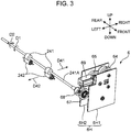
- FIG. 3 is a perspective view of the driving unit 6 (drive transmission device) and the aforementioned sheet discharge roller pairs 24 according to this embodiment.
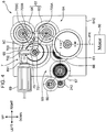
- FIG. 4 is a front view showing an internal structure of the driving unit 6.
- FIG. 5 is a front view of the interior of the driving unit 6 when the sheet discharge rollers 241 are driven to rotate in a forward direction.
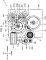
- FIG. 6 is a front view of the interior of the driving unit when the sheet discharge rollers 241 are driven to rotate in a reverse direction. Note that gear teeth of each gear are not shown in FIGS. 4 to 6 .
- the driving unit 6 rotates the aforementioned sheet discharge rollers 241.
- the driving unit 6 is arranged inside the apparatus body 10.
- the sheet discharge rollers 241 have a sheet discharge roller shaft 241A (rotary shaft).
- the sheet discharge roller shaft 241A is a rotary shaft in the rotation of the sheet discharge rollers 241.
- a plurality of sheet discharge rollers 241 are arranged at intervals in an axial direction of a sheet discharge roller shaft 241A.
- a plurality of driven rollers 242 are similarly arranged to respectively face the plurality of sheet discharge rollers 241.
- a sheet discharge roller gear 68 to be described later is fixed on a front end part of the sheet discharge roller shaft 241A. By rotating the sheet discharge roller shaft 241A by the sheet discharge roller gear 68, the sheet discharge rollers 241 are rotated in the forward and reverse directions.
- the sheet discharge rollers 241 rotate in the first direction (direction of an arrow D1 of FIGS. 2 and 3 ) about the sheet discharge roller shaft 241A, thereby discharging a sheet from the main conveyance path 22F toward the sheet discharging portion 13 ( FIG. 1 ) (arrow D21 of FIG. 2 , arrow D41 of FIG. 3 ). Further, the sheet discharge rollers 241 rotate in a second direction (direction of an arrow D2 of FIGS. 2 and 3 ) opposite to the first direction about the sheet discharge roller shaft 241A, thereby conveying a sheet into the reversing conveyance path 22B (arrow D22 of FIG. 2 , arrow D42 of FIG. 3 ).
- the driving unit 6 includes a supporting wall 6H, a driver 6A ( FIG. 4 ), a transmitter 6B ( FIG. 4 ) and a switcher 7 ( FIG. 4 ).
- the supporting wall 6H is a housing part of the driving unit 6.
- the supporting wall 6H includes a first supporting wall 6H1 and a second supporting wall 6H2.
- the first and second supporting walls 6H1, 6H2 are plate-like members extending in the vertical and lateral directions.
- the first and second supporting walls 6H1, 6H2 are arranged at a predetermined distance from each other in a front-rear direction.
- Each gear to be described later is rotatably supported on the first and second supporting walls 6H1, 6H2.
- the driver 6A can switch between drive stop and forward rotation drive and generates a rotational drive force for rotating the sheet discharge rollers 241 in the first direction in the forward rotation drive. Further, the driver 6A is capable of reverse rotation drive opposite to the forward rotation drive and generates a rotational drive force for rotating the sheet discharge rollers 241 in the second direction in the reverse rotation drive. In this embodiment, the driver 6A rotationally drives a transmission gear 65 ( FIG. 4 ) of the transmitter 6B to be described later in forward and reverse directions.
- the driver 6A includes a motor 60, a first gear 61 and a planetary gear mechanism 62.
- the motor 60 is a motor capable of generating the rotational drive force and rotating in a forward direction.
- the motor 60 is rotationally driven by an unillustrated controller according to a rotating direction of the sheet discharge rollers 241. Note that, in this embodiment, the motor 60 rotationally drives another member of the image forming apparatus 1. As an example, the aforementioned photoconductive drum 31 is rotated by the motor 60.
- the first gear 61 ( FIG. 4 ) is a rotary gear coupled to a drive shaft of the motor 60.
- the first gear 61 is coupled to a first planetary gear mechanism 63 of the planetary gear mechanism 62 to be described later.
- the first gear 61 is coupled to a first carrier 631 ( FIG. 5 ) of the first planetary gear mechanism 63.
- the planetary gear mechanism 62 is composed of two planetary gear assemblies.
- the planetary gear mechanism 62 transmits the rotational drive force of the motor 60 transmitted to the first gear 61 to the transmission gear 65. At this time, the forward rotation drive of the motor 60 is converted into forward and reverse rotation of the transmission gear 65.
- the planetary gear mechanism 62 includes a first planetary gear mechanism 63 and a second planetary gear mechanism 64.
- the first planetary gear mechanism 63 is coupled to the first gear 61 and the transmission gear 65 and transmits the rotational drive force of the motor 60 to the transmission gear 65. Further, the second planetary gear mechanism 64 is coupled to the first planetary gear mechanism 63 and the transmission gear 65 and transmits the rotational drive force of the motor 60 to the transmission gear 65.
- the switcher 7 changes the rotating directions of the first and second planetary gear mechanisms 63, 64 in correspondence with the forward and reverse rotation drives of the transmission gear 65. Note that the structures of the first planetary gear mechanism 63, the second planetary gear mechanism 64 and the switcher 7 are described in detail later.
- the transmitter 6B ( FIG. 4 ) is composed of a plurality of gears and transmits the rotational drive force from the driver 6A to the sheet discharge rollers 241.
- the transmitter 6B includes the transmission gear 65, a second gear 66 (second transmission gear), a third gear 67 and the sheet discharge roller gear 68.
- the transmission gear 65 is arranged on a most upstream side in the transmission of the rotational drive force out of the plurality of gears of the transmitter 6B.
- the transmission gear 65 is coupled to the planetary gear mechanism 62 of the driver 6A.
- the transmission gear 65 includes a transmission gear shaft 65A (see FIG. 7 ).
- the transmission gear shaft 65A is a rotary shaft in the rotation of the transmission gear 65.
- the transmission gear 65 is rotated about the transmission gear shaft 65A.
- the second gear 66 is arranged downstream of the transmission gear 65 in the transmission of the rotational drive force out of the plurality of gears of the transmitter 6B, and coupled to the transmission gear 65.
- the third gear 67 is arranged downstream of the second gear 66 in the transmission of the rotational drive force, and coupled to the second gear 66.
- the sheet discharge roller gear 68 is arranged downstream of the third gear 67 in the transmission of the rotational drive force, and coupled to the third gear 67.
- the sheet discharge roller gear 68 is fixed to the end part of the sheet discharge roller shaft 241A of the sheet discharge rollers 241 as described above.
- a broke line PR indicates a transmission path of the rotational drive force from the motor 60 to the sheet discharge roller gear 68.
- the transmission path of the rotational drive force is shown by broken line also in FIGS. 5 to 7 .
- FIG. 7 is a back view of the interior of the driving unit 6 according to this embodiment.
- FIG. 8 is a right side view of the driving unit 6.
- FIG. 9 is a front view of the planetary gear mechanism 62 of the driving unit 6.
- FIG. 10 is a sectional view along line A-A of FIG. 9 of the planetary gear mechanism 62.
- FIG. 11 is an exploded sectional view of the planetary gear mechanism 62 of FIG. 10 .
- FIG. 12 , 13A and 13B are exploded perspective views of the planetary gear mechanism 62 of FIG. 10 . Note that FIGS.
- FIGS. 13A and 13B are views showing the same members, a rotating direction of each gear is different.
- FIG. 13A shows a case where the sheet discharge rollers 241 are rotated in the forward direction (rotated in the first direction) and
- FIG. 13B shows a case where the sheet discharge rollers 241 are rotated in the reverse direction (rotated in the second direction).
- the first planetary gear mechanism 63 includes the first carrier 631 (first input gear), a first sun gear 632, a first inner gear 633 (first output gear) and a pair of first planetary gears 635.
- the first carrier 631 is coupled to the first gear 61 and the rotational drive force of the motor 60 is input to the first carrier 631.
- the first carrier 631 includes a first shaft 631A (first shaft portion) extending in the front-rear direction.
- the first sun gear 632 and the first inner gear 633 are externally fitted on the first shaft 631A from front and rear.
- the first carrier 631 is coupled to a second carrier 641 to be described later.
- a pair of shaft portions 631B project on one side part of the first carrier 631 ( FIG. 13A ).
- the first planetary gears 635 are respectively rotatably supported on this pair of shaft portions 631B.
- the first inner gear 633 is arranged on the same axis as the first carrier 631 and faces one side part of the first carrier 631.
- the first inner gear 633 is externally fitted on the first shaft 631A from rear.
- the outer portion (the first outer gear portion) of the first inner gear 633 is engaged with the transmission gear 65 and transmits the rotational drive force to the transmission gear 65.
- the first inner gear 633 includes a first hollow cylindrical portion 633H (output gear hollow cylindrical portion).
- the first hollow cylindrical portion 633H is a hollow cylindrical part arranged to cover the one side part (revolutionary path of the first planetary gear 635) of the first carrier 631.
- the pair of first planetary gears 635 are arranged to be capable of rotating and revolving in the first hollow cylindrical portion 633H.
- the first planetary gears 635 are capable of rotating about the shaft portions 631B and revolving about the first shaft 631A by being engaged with a gear (first inner peripheral gear portion) formed on the inner peripheral surface of the first inner gear 633.
- the rotational drive force is transmitted between the first carrier 631 and the first inner gear 633 via the pair of first planetary gears 635.
- the first planetary gears 635 are engageable with a gear portion 632B ( FIG. 13A ) (first exposed gear portion) of the first sun gear 632.
- the gear portion 632B of the first sun gear 632 inserted into the hollow cylindrical interior (input gear hollow cylindrical portion) of the first carrier 631 is exposed from an opening GH of the first carrier 631.
- the gear portion 632B and the first planetary gears 635 are engageable.
- the first sun gear 632 is arranged on the same axis as the first carrier 631 and the first inner gear 633, and faces another side part of the first carrier 631.
- the first sun gear 632 is externally fitted on the first shaft 631A from front.
- the first sun gear 632 is rotatable about the first shaft 631A.
- a first projection 703A of a rotary arm 70 to be described later is engageable with a restricted portion 632A ( FIG. 13A ) of the first sun gear 632.
- the rotation of the first sun gear 632 about the first shaft 631A is restricted or permitted. If the rotation of the first sun gear 632 about the first shaft 631A is restricted, the first carrier 631 relatively rotates with respect to the first sun gear 632.
- the second planetary gear mechanism 64 includes the second carrier 641 (second input gear), a second sun gear 642, a second inner gear 643 (second output gear) and a pair of second planetary gears 645.
- the second carrier 641 is coupled to the first carrier 631 and the rotational drive force of the motor 60 is input from the first carrier 631 to the second carrier 641.
- the second carrier 641 includes a second shaft 641A extending in the front-rear direction.
- the second sun gear 642 and the second inner gear 643 are externally fitted on the second shaft 641A from front and rear.
- a pair of shaft portions 641B project on one side part of the second carrier 641 ( FIG. 13A ).
- the second planetary gears 645 are respectively rotatably supported on this pair of shaft portions 641B.
- the second inner gear 643 is arranged on the same axis as the second carrier 641 and faces one side part of the second carrier 641.
- the second inner gear 643 is externally fitted on the second shaft 641A from rear.
- the outer portion (the second outer gear portion) of the second inner gear 643 is engaged with the transmission gear 65 and transmits the rotational drive force to the transmission gear 65.
- the second inner gear 643 includes a second hollow cylindrical portion 643H (output gear hollow cylindrical portion).
- the second hollow cylindrical portion 643H is a hollow cylindrical part arranged to cover the one side part (revolutionary path of the second planetary gear 645) of the second carrier 641.
- the pair of second planetary gears 645 are arranged to be capable of rotating and revolving in the second hollow cylindrical portion 643H.
- the second planetary gears 645 are capable of rotating about the shaft portions 641B and revolving about the second shaft 641A by being engaged with a gear (second inner peripheral gear portion) formed on the inner peripheral surface of the second inner gear 643.
- the rotational drive force is transmitted between the second carrier 641 and the second inner gear 643 via the pair of second planetary gears 645.
- the second planetary gears 645 are engageable with a gear portion 642B ( FIG. 13A ) (second exposed gear portion) of the second sun gear 642.
- the second sun gear 642 is arranged on the same axis as the second carrier 641 and the second inner gear 643 and faces another side part of the second carrier 641.
- the second sun gear 642 is externally fitted on the second shaft 641A from front.
- the second sun gear 642 is rotatable about the second shaft 641A.
- a second projection 703B of the rotary arm 70 to be described later is engageable with a restricted portion 642A ( FIG. 13A ) of the second sun gear 642.
- the rotation of the second sun gear 642 about the second shaft 641A is restricted or permitted. If the rotation of the second sun gear 642 about the second shaft 641A is restricted, the second carrier 641 relatively rotates about the second sun gear 642.
- the rotational drive force is transmitted among the first gear 61 ( FIG. 7 ), the first carrier 631 and the second carrier 641 in the first and second planetary gear mechanisms 63, 64 constituting the planetary gear mechanism 62.
- the rotational drive force is then transmitted from the first and second inner gears 633, 643 to the transmission gear 65.
- the rotating direction of the transmission gear 65 can be switched by the first and second planetary gear mechanisms 63, 64.
- the sheet discharge rollers 241 are rotated in the first and second directions while the motor 6 is rotated in the forward direction.
- the switcher 7 includes a solenoid 69 and the rotary arm 70 (switching member).
- the rotary arm 70 restricts the rotation of one sun gear while permitting the rotation of the other sun gear by engaging one of the restricted portion 632A ( FIG. 13A ) of the first sun gear 632 and the restricted portion 642A ( FIG. 13A ) of the second sun gear 642.
- the rotary arm 70 is an arm member externally fitted on the transmission gear shaft 65A of the transmission gear 65.
- the rotary arm 70 includes an arm shaft portion 701, a first arm 702 and a second arm 703 ( FIG. 4 ).
- the arm shaft portion 701 serves as a supporting point in the rotation of the rotary arm 70.
- the arm shaft portion 701 is arranged on the same axis as the transmission gear shaft 65A.
- the arm shaft portion 701 has a hollow cylindrical shape and is externally fitted on the transmission gear shaft 65A.
- the first arm 702 extends substantially upward from the arm shaft portion 701 and is coupled to the solenoid 69.
- the second arm 703 extends substantially rightward from the arm shaft portion 701 to enter a space between the first and second sun gears 632, 642 from left ( FIG. 4 ).
- the second arm 703 includes the first projection 703A, the second projection 703B and an arm extending portion 703C.
- the first projection 703A is a projection projecting downward on a tip part (right end part) of the second arm 703.
- the first projection 703A is engageable with the restricted portion 632A of the first sun gear 632 according to the rotation of the rotary arm 70 about the arm shaft portion 701 (clockwise rotation).
- the second projection 703B is a projection projecting upward on a tip part of the second arm 703.
- the second projection 703B is engageable with the restricted portion 642A of the second sun gear 642 according to the rotation of the rotary arm 70 about the arm shaft portion 701 (counterclockwise rotation).
- the rotating direction of the transmission gear 65 can be switched by the second arm 703 engaging the first sun gear 632 or the second sun gear 642.
- the arm extending portion 703C is a projection projecting upward from the second arm 703 on a side closer to the arm shaft portion 701 than the second projection 703B.
- An unillustrated biasing spring is mounted on the arm extending portion 703C.
- the solenoid 69 is controlled according to the rotating direction of the sheet discharge rollers 241 and projects and retracts to correspond to the forward and reverse rotation drives of the driver 6A.
- the solenoid 69 includes a projecting/retracting shaft 691.
- the projecting/retracting shaft 691 can change a state thereof between a projecting state to project rightward from the solenoid 69 and a retracting state to retract into the inside of the solenoid 69 from the projecting state.
- the first arm 702 of the aforementioned rotary arm 70 is coupled to a tip part (right end part) of the projecting/retracting shaft 691.
- the solenoid 69 moves the rotary arm 70 to engage the second arm 703 of the rotary arm 70 with the second sun gear 642 against a biasing force of the biasing spring to be described later in accordance with the reverse rotation drive of the driver 6A. Specifically, the solenoid 69 rotates the rotary arm 70 about the arm shaft portion 701 and engages the second projection 703B with the restricted portion 642A ( FIG. 13A ) of the second sun gear 642.
- the driving unit 6 includes a biasing portion 6C ( FIG. 4 ).
- the biasing portion 6C biases the transmission gear shaft 65A of the transmission gear 65 toward the driver 6A.
- the biasing portion 6C is composed of the second arm 703 and the unillustrated biasing spring described above.
- the biasing spring is a spring member extending from a fixing portion inside the apparatus body 10 and to be engaged with the arm extending portion 703C of the second arm 703.
- the biasing spring biases the second arm 703 rightward and downward.
- the transmission gear shaft 65A arranged on the same axis as the first arm 702 is biased rightward and downward.
- the biasing spring biases the rotary arm 70 toward the first sun gear 632 and engages the first projection 703A of the rotary arm 70 with the restricted portion 632A of the first sun gear 632.
- an engagement destination of the rotary arm 70 is switched between the first and second sun gears 632 and 642 according to the projecting and retracting motions of the solenoid 69.
- the solenoid 69 is set in the projecting state to correspond to the forward rotation drive of the sheet discharge rollers 241.
- the projecting/retracting shaft 691 projects in a direction of an arrow D61 of FIG. 5 from the solenoid 69.
- the rotary arm 70 rotates about the arm shaft portion 701 and the first projection 703A of the second arm 703 engages the first sun gear 632 (arrow D62 of FIG. 5 ).
- the rotation of the first sun gear 632 is restricted.
- the first gear 61 is rotated in a direction of an arrow D601 of FIG. 5 (an arrow D91 of FIG. 7 ).
- the first carrier 631 of the first planetary gear mechanism 63 engaged with the first gear 61 rotates in a direction of an arrow D602 of FIG. 5 (an arrow D92 of FIG. 7 ) and an arrow direction of FIG. 13A .
- the second carrier 641 engaged with the first carrier 631 rotates in a direction of an arrow D603 of FIG. 5 (an arrow D94 of FIG. 7 ) and an arrow direction of FIG. 13A .
- the first carrier 631 and the first inner gear 633 rotate in the same direction via the pair of planetary gears 635.
- the first inner gear 633 rotates in an arrow direction of FIG. 13A .
- the rotation of the second sun gear 642 is permitted by the second projection 703B.
- the second carrier 641 and the second inner gear 643 rotate in opposite directions and the second inner gear 643 rotates in an arrow direction of FIG. 13A .
- the transmission gear 65 engaged with the first and second inner gears 633, 643 rotates in a direction of an arrow D604 of FIG. 5 (an arrow D96 of FIG. 7 ) and an arrow direction of FIG. 13A .
- the sheet discharge rollers 241 are rotated in the direction of the arrow D1 (first direction) of FIGS. 2 and 3 and the sheet is conveyed in a direction of an arrow D21 of FIG. 2 , an arrow D41 of FIG. 3 and an arrow DS1 of FIG. 5 .
- the sheet is discharged to the sheet discharging portion ( FIG. 1 ).
- the reverse rotation drive (arrow D2 of FIGS. 2 and 3 ) of the sheet discharge rollers 241 by the driving unit 6 is described.
- the sheet discharge rollers 241 are controlled from the forward rotation drive to the reverse rotation drive in a state where a leading end side of the sheet is exposed upwardly of the sheet discharging portion 13 and the trailing edge of the sheet is sandwiched by the sheet discharge roller pairs 24.
- the sheet is conveyed to the reversing conveyance path 22B ( FIGS. 1 and 2 ).
- the solenoid 69 is set in the retracting state to correspond to the reverse rotation drive of the sheet discharge rollers 241.
- the projecting/retracting shaft 691 retracts in a direction of an arrow D71 of FIG. 6 into the inside of the solenoid 69.
- the rotary arm 70 rotates about the arm shaft portion 701 in the reverse direction and the second projection 703B of the second arm 703 engages the second sun gear 642 (arrow D72 of FIG. 6 ).
- the rotation of the second sun gear 642 is restricted.
- the biasing spring biases the arm extending portion 703C rightward and downward.
- the second arm 703 of the rotary arm 70 is moved upward against a biasing force of the biasing spring.
- the first gear 61 is rotated in a direction of an arrow D701 of FIG. 6 .
- the rotating direction of the first gear 61 is the same as the direction of the arrow D601 of FIG. 5 described above.
- the first carrier 631 of the first planetary gear mechanism 63 engaged with the first gear 61 rotates in a direction of an arrow D702 of FIG. 6 and an arrow direction of FIG. 13B .
- the second carrier 641 engaged with the first carrier 631 rotates in a direction of an arrow D703 of FIG. 6 and an arrow direction of FIG. 13B .
- the sheet discharge rollers 241 are rotated in the direction of the arrow D2 (second direction) of FIGS. 2 and 3 and the sheet is conveyed in a direction of an arrow D22 of FIG. 2 , an arrow D42 of FIG. 3 and an arrow DS2 of FIG. 6 .
- the sheet is conveyed into the reversing conveyance path 22B ( FIGS. 1 and 2 ).
- the rotation of one of the first and second sun gears 632, 642 is restricted.
- the rotation of the first sun gear 632 of the first planetary gear mechanism 63 of FIG. 13A is restricted.
- the second carrier 641 and the second inner gear 643 are rotated in directions opposite to each other.
- the second sun gear 642 idly rotates at a high speed by meshing between the pair of second planetary gears 645 and the gear portion 642B.
- a problem that meshing noise is significant in meshing between the pair of second planetary gears 645 and the gear portion 642B of the second sun gear 642 was newly found out.
- the above meshing noise was found to be significant when a rotational speed of each carrier (first carrier 631 or second carrier 641) is 200 rpm or higher. In this embodiment, the rotational speed of the first sun gear 632 or the second sun gear 642 at this time reaches 1600 rpm.
- meshed parts of the gear portion 632B of the first sun gear 632 and the pair of planetary gears 635 and meshed parts of the gear portion 642B of the second sun gear 642 and the pair of secondary planetary gears 645 are characterized.
- meshed parts of the gear portion 642B of the second sun gear 642 and the pair of second planetary gears 645 are described below, the meshed parts of the gear portion 632B of the first sun gear 632 and the pair of planetary gears 635 also have similar characteristics.
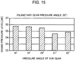
- FIG. 14 is a diagram showing pressure angles of the gear portion 642B of the second sun gear 642 and the second planetary gear 645 according to this embodiment. Further, FIG. 15 is a graph showing a relationship between the pressure angle of the gear portion 642B of the second sun gear 642 and a sound pressure level of the meshing noise.
- a pitch circle 642M of the gear portion 642B of the second sun gear 642 and a pitch circle 645M of the second planetary gear 645 are shown in FIG. 14 .
- a pressure angle ⁇ 1 ( ⁇ 1B) of the gear portion 642B of the second sun gear 642 is an angle formed between a tangent to a tooth surface of the gear portion 642B on the pitch circle 642M and a line segment connecting centers of rotation of the both gears.
- a pressure angle ⁇ 2 ( ⁇ 2B) of the second planetary gear 645 is an angle formed between a tangent to a tooth surface of the second planetary gear 645 on the pitch circle 645M and the line segment connecting centers of rotation of the both gears.
- the sound pressure level of the meshing noise is minimized by setting the pressure angle ⁇ 1 of the gear portion 642 of the second sun gear 642 to 21°. Note that, in addition to data shown in FIG. 15 , it was found out that the sound pressure level of the meshing noise became lower in a range of 20° ⁇ 1 ⁇ 22°, became even lower in a range of 20.5° ⁇ 1 ⁇ 22° and became lowest in a range of 21° ⁇ 1 ⁇ 22° as a result of further minutely changing the pressure angle ⁇ 1 of the gear portion 642B of the second sun gear 642.
- the rotating direction of the sheet discharge rollers 241 can be switched with the motor 60 kept driven to rotate in the forward direction by restricting the rotation of one of the first and second sun gears 632, 642 by the rotary arm 70 of the switcher 7. Further, the meshing noise of the exposed gear portion of the sun gear and the planetary gears is suppressed in the planetary gear mechanism in which the rotation of the sun gear is not restricted.
- each carrier first carrier 631, second carrier 642
- first carrier 631, second carrier 642 is set at a high rotational speed like 200 rpm
- the meshing noise of the gear portion of the sun gear and the planetary gear is suppressed.
- At least one of the gear portion of the sun gear and the planetary gear has 16 teeth or less, whereby the meshing noise of the gear portion of the sun gear and the planetary gear is suppressed even if the rotational speed of the gear portion of the sun gear is set high.
- the gear teeth of the gear portion of the sun gear can be protected by enclosing the gear portion of the sun gear by the aforementioned input gear hollow cylindrical portion. Further, since an outer peripheral part of the gear portion of the sun gear can be exposed by as much as necessary to be meshed with the planetary gear, noise caused by the vibration of the gear portion of the sun gear can be contained.
- the planetary gear can be covered by the aforementioned output gear hollow cylindrical portion, the meshing noise of the exposed gear portion of the sun gear and the planetary gear can be further suppressed.
- the driving unit 6 according to the embodiment of the present disclosure and the sheet conveying device 2 and the image forming apparatus 1 provided with the same have been described above. According to such configurations, the sheet conveying device and the image forming apparatus are provided in which the meshing noise of the exposed gear portion of the sun gear and the planetary gear is suppressed. Note that the present disclosure is not limited to this and, for example, the following modification can be employed.
- the sheet discharge rollers 241 have been described as a rotary body in the above embodiment, the present disclosure is not limited to this. Another rotary body may be rotationally driven by the driving unit 6.
Landscapes
- Engineering & Computer Science (AREA)
- Mechanical Engineering (AREA)
- General Engineering & Computer Science (AREA)
- Physics & Mathematics (AREA)
- General Physics & Mathematics (AREA)
- Handling Of Sheets (AREA)
- Retarders (AREA)
- Multimedia (AREA)
- Signal Processing (AREA)
- Gears, Cams (AREA)
- Gear Transmission (AREA)
- Electrophotography Configuration And Component (AREA)
- Health & Medical Sciences (AREA)
- Biomedical Technology (AREA)
- General Health & Medical Sciences (AREA)
Abstract
Description
- This application is based on Japanese Patent Application No.
2016-206819 - The present disclosure relates to a drive transmission device for transmitting a rotational drive force to a rotary body, and a sheet conveying device and an image forming apparatus provided with the same.
- Conventionally, a drive transmission device is known which transmits a rotational drive force to a rotary body. The drive transmission device transmits a rotational drive force to a conveyor roller pair of an image forming apparatus. The conveyor roller pair conveys a sheet in a predetermined direction. Further, sun gears and planetary gears are used in the drive transmission device. In this technique, two sun gears are provided and rotating directions of the conveyor rollers are controlled by selectively fixing the rotation of either one of the sun gears.
- A drive transmission device according to one aspect of the present disclosure includes a rotary body, a driver and a transmitter. The rotary body has a rotary shaft and rotates about the rotary shaft in a first rotating direction and a second rotating direction opposite to the first rotating direction. The driver includes a motor switchable between drive stop and forward rotation drive and capable of converting a rotational drive force generated by the motor in the forward rotation drive into mutually different rotating directions. The transmitter rotates the rotary body in the first rotating direction and the second rotating direction by transmitting the rotational drive force from the driver to the rotary body. The transmitter includes a transmission gear coupled to the transmitter. The driver includes a first planetary gear mechanism, a second planetary gear mechanism and a switcher. The first planetary gear mechanism is coupled to the motor and the transmission gear and transmits the rotational drive force of the motor to the transmission gear. The second planetary gear mechanism is coupled to the first planetary gear mechanism and the transmission gear and transmits the rotational drive force of the motor to the transmission gear. The switcher changes rotating directions of the first and second planetary gear mechanisms in correspondence with a rotating direction of the rotary body. The first planetary gear mechanism includes a first input gear, a first output gear, a first sun gear and a first planetary gear. The first input gear has a first shaft portion, and the rotational drive force of the motor is input to the first input gear. The first output gear has a first outer peripheral gear portion to be engaged with the transmission gear and a first inner peripheral gear portion, is arranged to face one side part of the first input gear on the same axis as the first input gear and rotatable about the first shaft portion, and transmits the rotational drive force to the transmission gear. The first sun gear has a first exposed gear portion exposed on the one side part of the first input gear and is arranged to face another side part of the first input gear on the same axis as the first input gear and rotatable about the first shaft portion. The first planetary gear is supported in such a manner as to be capable of rotating and revolving about the first shaft portion on the one side part of the first input gear, and engaged with the first inner peripheral gear portion and the first exposed gear portion. The second planetary gear mechanism includes a second input gear, a second output gear, a second sun gear and a second planetary gear. The second input gear has a second shaft portion and is engaged with the first input gear, and the rotational drive force of the motor is input to the second input gear. The second output gear has a second outer peripheral gear portion to be engaged with the transmission gear and a second inner peripheral gear portion, is arranged to face one side part of the second input gear on the same axis as the second input gear and rotatable about the second shaft portion and transmits the rotational drive force to the transmission gear. The second sun gear has a second exposed gear portion exposed on the one side part of the second input gear and is arranged to face another side part of the second input gear on the same axis as the second input gear and rotatable about the second shaft portion. The second planetary gear is supported in such a manner as to be capable of rotating and revolving about the second shaft portion on the one side part of the second input gear and engaged with the second inner peripheral gear portion and the second exposed gear portion. The switcher includes a switching member configured to engage one of the first and second sun gears, thereby restricting the rotation of the one sun gear and permitting the rotation of the other sun gear. The transmission gear is rotated in a third rotating direction by the first and second output gears to rotate the rotary body in the first rotating direction when the rotation of the first sun gear is restricted by the switching member, and the transmission gear is rotated in a fourth rotating direction opposite to the third rotating direction by the first and second output gears to rotate the rotary body in the second rotating direction when the rotation of the second sun gear is restricted by the switching member. Relationships of θ2A+0.5°≤θ1A≤θ2A+1.5° and θ2B+0.5°≤θ1B≤θ2B+1.5° are satisfied if θ1A(°) denotes a pressure angle of gear teeth of the first exposed gear portion of the first sun gear and θ2A(°) denotes a pressure angle of gear teeth of the first planetary gear in meshing between the gear teeth of the first exposed gear portion and the gear teeth of the first planetary gear and θ1B(°) denotes a pressure angle of gear teeth of the second exposed gear portion of the second sun gear and θ2B(°) denotes a pressure angle of gear teeth of the second planetary gear in meshing between the gear teeth of the second exposed gear portion and the gear teeth of the second planetary gear.
- Further, a sheet conveying device according to another aspect of the present disclosure includes the above drive transmission device, and a conveyor roller configured to convey a sheet, the conveyor roller serving as the rotary body.
- Further, an image forming apparatus according to another aspect of the present disclosure includes an apparatus body, an image forming unit, a sheet conveyance path, the above sheet conveying device and a sheet discharging portion. The image forming unit is arranged in the apparatus body and forms an image on a sheet. The sheet conveyance path allows the sheet to pass through the image forming unit. The sheet conveying device is arranged in the sheet conveyance path. The sheet having the image formed thereon is discharged to the sheet discharging portion.
-
-
FIG. 1 is a sectional view showing an internal structure of an image forming apparatus according to one embodiment of the present disclosure, -
FIG. 2 is a schematic sectional view showing a sheet conveyance path of the image forming apparatus according to the one embodiment of the present disclosure, -
FIG. 3 is a perspective view of a drive transmission device and sheet discharge roller pairs according to the one embodiment of the present disclosure, -
FIG. 4 is a front view showing an internal structure of the drive transmission device according to the one embodiment of the present disclosure, -
FIG. 5 is a front view of the interior of the drive transmission device when sheet discharge rollers are driven to rotate in a forward direction, -
FIG. 6 is a front view of the interior of the drive transmission device when the sheet discharge rollers are driven to rotate in a reverse direction, -
FIG. 7 is a back view of the interior of the drive transmission device according to the one embodiment of the present disclosure, -
FIG. 8 is a side view of the drive transmission device according to the one embodiment of the present disclosure, -
FIG. 9 is a front view of a planetary gear mechanism of the drive transmission device according to the one embodiment of the present disclosure, -
FIG. 10 is a sectional view of the planetary gear mechanism of the drive transmission device according to the one embodiment of the present disclosure, -
FIG. 11 is an exploded sectional view of the planetary gear mechanism of the drive transmission device according to the one embodiment of the present disclosure, -
FIG. 12 is an exploded perspective view of the planetary gear mechanism of the drive transmission device according to the one embodiment of the present disclosure, -
FIG. 13A is an exploded perspective view of the planetary gear mechanism of the drive transmission device according to the one embodiment of the present disclosure, -
FIG. 13B is an exploded perspective view of the planetary gear mechanism of the drive transmission device according to the one embodiment of the present disclosure, -
FIG. 14 is a schematic diagram showing pressure angles of a sun gear and a planetary gear according to the one embodiment of the present disclosure, and -
FIG. 15 is a graph showing a relationship of the pressure angle of the sun gear and a sound pressure level of meshing noise. - Hereinafter, an embodiment of the present disclosure is described with reference to the drawings.
FIG. 1 is a side view in section showing an internal structure of animage forming apparatus 1 according to one embodiment of the present disclosure.FIG. 2 is a schematic sectional view showing amain conveyance path 22F and a reversingconveyance path 22B of theimage forming apparatus 1. Although a monochrome printer is illustrated as theimage forming apparatus 1 here, the image forming apparatus may be a copier, a facsimile machine or a complex machine provided with these functions or an apparatus for forming a color image. - The
image forming apparatus 1 includes anapparatus body 10 having a housing structure having a substantially rectangular parallelepiped shape, and asheet feeding unit 20, an image forming unit 30, afixing unit 40 and atoner container 50 housed in thisapparatus body 10. - A
front cover 11 and arear cover 12 are respectively provided on a front surface side and a rear surface side of theapparatus body 10. By opening thefront cover 11, thetoner container 50 is exposed. In this way, a user can pull out thetoner container 50 from the front surface side of theapparatus body 10 when toner runs out. Therear cover 12 is a cover opened at the time of a sheet jam or maintenance. Each unit of the image forming unit 30 and the fixingunit 40 can be pulled out from the rear surface side of theapparatus body 10 by opening therear cover 12. Further, an unillustrated left cover and an unillustrated right cover on a side opposite to the left cover are respectively disposed on side surfaces of theapparatus body 10 to extend in a vertical direction. Further, asheet discharging portion 13 to which a sheet having an image formed thereon is to be discharged is provided on the upper surface of theapparatus body 10. Various devices for performing image formation are housed in an internal space defined by thefront cover 11, therear cover 12, the left cover, the right cover and thesheet discharging portion 13. - The
sheet feeding unit 20 includes asheet cassette 21 for storing sheets to which an image forming process is to be applied. The upper surface of a part of thesheet cassette 21 housed in theapparatus body 10 is covered by a sheetcassette ceiling plate 21U. - The
sheet cassette 21 includes a sheet storage space SP for storing a bundle of the sheets and alift plate 21 configured to be lifted up by aspring 21S to feed the sheets of the bundle. Further, a pair of side walls 21P1 (seeFIG. 2 ) are arranged on both end parts of thelift plate 21P in a sheet width direction. Asheet delivery unit 21A is provided on a rear end side of thesheet cassette 21. Asheet feed roller 21B for feeding the uppermost sheet of the sheet bundle on thelift plate 21P one by one in a sheet conveying direction is arranged in thissheet delivery unit 21A. - The image forming unit 30 performs an image forming process of forming a toner image on the sheet fed from the
sheet feeding unit 20. The image forming unit 30 includes aphotoconductive drum 31 and a chargingdevice 32, an exposure device (not shown inFIG. 1 ), a developingdevice 33, atransfer roller 34 and acleaning device 35 arranged around thisphotoconductive drum 31. The image forming unit 30 is disposed between the left and right covers. - The
photoconductive drum 31 rotates about a shaft thereof and an electrostatic latent image and a toner image are formed on a peripheral surface thereof. The chargingdevice 32 is for uniformly charging the surface of thephotoconductive drum 31, and includes a charging roller in contact with thephotoconductive drum 31. Thecleaning device 35 includes a cleaning blade and the like, cleans toner adhering to the peripheral surface of thephotoconductive drum 31 after the transfer of the toner image and conveys the cleaned toner to an unillustrated collection device. - The exposure device includes optical devices such as a laser light source, a mirror and a lens and forms an electrostatic latent image by irradiating light modulated based on image data given from an external apparatus such as a personal computer to the peripheral surface of the
photoconductive drum 31. The developingdevice 33 supplies the toner to the peripheral surface of thephotoconductive drum 31 to develop the electrostatic latent image on thephotoconductive drum 31 and form a toner image. - The
transfer roller 34 is a roller for transferring a toner image formed on the peripheral surface of thephotoconductive drum 31 to a sheet and forms a transfer nip portion together with thephotoconductive drum 31. A transfer bias having a polarity opposite to that of the toner is given to thistransfer roller 34. - The fixing
unit 40 performs a fixing process of fixing a transferred toner image onto a sheet. The fixingunit 40 includes a fixingroller 41 having a heating source inside and apressure roller 42 configured to form a fixing nip portion between the fixingroller 41 and thepressure roller 42 by being pressed into contact with the fixingroller 41. When a sheet having a toner image transferred thereto is passed through the fixing nip portion, the toner image is fixed onto the sheet by being heated by the fixingroller 41 and pressed by thepressure roller 42. - The
toner container 50 stores the toner to be supplied to the developingdevice 33 through asupply port 521. - The
main conveyance path 22F (sheet conveyance path) and the reversingconveyance path 22B are provided in theapparatus body 10 to convey a sheet (FIGS. 1 and2 ). Themain conveyance path 22F extends from thesheet delivery unit 21A of thesheet feeding unit 20 to a sheet discharge opening 14 provided to face thesheet discharging portion 13 on the upper surface of theapparatus body 10 via the image forming unit 30 and the fixingunit 40. Specifically, themain conveyance path 22F is a conveyance path along which the sheet is conveyed to pass through the image forming unit 30. Themain conveyance path 22F is a conveyance path for conveying the sheet on thelift plate 21P of thesheet cassette 21 in the predetermined sheet conveying direction. The reversingconveyance path 22B is a conveyance path for returning a sheet printed on one side to a part of themain conveyance path 22F upstream of the image forming unit 30 in printing both sides of the sheet. A duplex conveyor roller pair 342 (FIG. 2 ) is arranged in the reversingconveyance path 22B. -
Registration rollers 23 are arranged in a part of themain conveyance path 22F upstream of the transfer nip portion between thephotoconductive drum 31 and thetransfer roller 34. In other words, theregistration rollers 23 are arranged downstream of thesheet feed roller 21B in the sheet conveying direction. Theregistration rollers 23 regulate the position of the sheet in a sheet width direction perpendicular to the sheet conveying direction. Further, the sheet is temporarily stopped at theregistration rollers 23 and fed to the transfer nip portion at a predetermined timing for image transfer after a skew correction is made. A plurality of conveyor rollers for conveying the sheet are arranged at suitable positions of themain conveyance path 22F and the reversingconveyance path 22B. For example, sheet discharge roller pairs 24 are arranged near thesheet discharge opening 14. The sheetdischarge roller pair 24 includes a sheet discharge roller 241 (rotary body, conveyor roller) and a drivenroller 242. Thesheet discharge rollers 241 convey a sheet having an image formed on a surface. The drivenrollers 242 rotate, following thesheet discharge rollers 241. Note that the sheet discharge roller pairs 24 are arranged on a side near thesheet discharging portion 13 in themain conveyance path 22F. By rotating thesheet discharge rollers 241 in a first direction to be described alter, the sheet is discharged to thesheet discharging portion 13. Further, a sheet conveying device 2 arranged in themain conveyance path 22F for conveying a sheet is constituted by the sheet discharge roller pairs 24 including thesheet discharge rollers 241 and adriving unit 6 to be described later. - The reversing
conveyance path 22B is formed between the outer side surface of a reversingunit 25 and the inner surface of therear cover 12 of theapparatus body 10. Note that thetransfer roller 34 and theregistration rollers 23 are mounted on the inner side surface of the reversingunit 25. Therear cover 12 and the reversingunit 25 are respectively rotatable about a supportingpoint portion 121 provided on the lower ends thereof. If a sheet jam occurs in the reversingconveyance path 22B, therear cover 12 is opened. If a sheet jam occurs in themain conveyance path 22F or if the unit including thephotoconductive drum 31 or the developingdevice 33 is taken out, the reversingunit 25 is opened in addition to therear cover 12. - Next, the driving
unit 6 according to this embodiment is described with reference toFIGS. 3 to 6 in addition toFIGS. 1 and2 .FIG. 3 is a perspective view of the driving unit 6 (drive transmission device) and the aforementioned sheet discharge roller pairs 24 according to this embodiment.FIG. 4 is a front view showing an internal structure of thedriving unit 6.FIG. 5 is a front view of the interior of thedriving unit 6 when thesheet discharge rollers 241 are driven to rotate in a forward direction.FIG. 6 is a front view of the interior of the driving unit when thesheet discharge rollers 241 are driven to rotate in a reverse direction. Note that gear teeth of each gear are not shown inFIGS. 4 to 6 . - The driving
unit 6 rotates the aforementionedsheet discharge rollers 241. The drivingunit 6 is arranged inside theapparatus body 10. With reference toFIG. 3 , thesheet discharge rollers 241 have a sheetdischarge roller shaft 241A (rotary shaft). The sheetdischarge roller shaft 241A is a rotary shaft in the rotation of thesheet discharge rollers 241. As shown inFIG. 3 , a plurality ofsheet discharge rollers 241 are arranged at intervals in an axial direction of a sheetdischarge roller shaft 241A. Further, a plurality of drivenrollers 242 are similarly arranged to respectively face the plurality ofsheet discharge rollers 241. A sheetdischarge roller gear 68 to be described later is fixed on a front end part of the sheetdischarge roller shaft 241A. By rotating the sheetdischarge roller shaft 241A by the sheetdischarge roller gear 68, thesheet discharge rollers 241 are rotated in the forward and reverse directions. - Specifically, the
sheet discharge rollers 241 rotate in the first direction (direction of an arrow D1 ofFIGS. 2 and3 ) about the sheetdischarge roller shaft 241A, thereby discharging a sheet from themain conveyance path 22F toward the sheet discharging portion 13 (FIG. 1 ) (arrow D21 ofFIG. 2 , arrow D41 ofFIG. 3 ). Further, thesheet discharge rollers 241 rotate in a second direction (direction of an arrow D2 ofFIGS. 2 and3 ) opposite to the first direction about the sheetdischarge roller shaft 241A, thereby conveying a sheet into the reversingconveyance path 22B (arrow D22 ofFIG. 2 , arrow D42 ofFIG. 3 ). - The driving
unit 6 includes a supportingwall 6H, adriver 6A (FIG. 4 ), atransmitter 6B (FIG. 4 ) and a switcher 7 (FIG. 4 ). - The supporting
wall 6H is a housing part of thedriving unit 6. The supportingwall 6H includes a first supporting wall 6H1 and a second supporting wall 6H2. As shown inFIG. 3 , the first and second supporting walls 6H1, 6H2 are plate-like members extending in the vertical and lateral directions. The first and second supporting walls 6H1, 6H2 are arranged at a predetermined distance from each other in a front-rear direction. Each gear to be described later is rotatably supported on the first and second supporting walls 6H1, 6H2. - The
driver 6A can switch between drive stop and forward rotation drive and generates a rotational drive force for rotating thesheet discharge rollers 241 in the first direction in the forward rotation drive. Further, thedriver 6A is capable of reverse rotation drive opposite to the forward rotation drive and generates a rotational drive force for rotating thesheet discharge rollers 241 in the second direction in the reverse rotation drive. In this embodiment, thedriver 6A rotationally drives a transmission gear 65 (FIG. 4 ) of thetransmitter 6B to be described later in forward and reverse directions. Thedriver 6A includes amotor 60, afirst gear 61 and aplanetary gear mechanism 62. - The
motor 60 is a motor capable of generating the rotational drive force and rotating in a forward direction. Themotor 60 is rotationally driven by an unillustrated controller according to a rotating direction of thesheet discharge rollers 241. Note that, in this embodiment, themotor 60 rotationally drives another member of theimage forming apparatus 1. As an example, the aforementionedphotoconductive drum 31 is rotated by themotor 60. - The first gear 61 (
FIG. 4 ) is a rotary gear coupled to a drive shaft of themotor 60. Thefirst gear 61 is coupled to a firstplanetary gear mechanism 63 of theplanetary gear mechanism 62 to be described later. Specifically, thefirst gear 61 is coupled to a first carrier 631 (FIG. 5 ) of the firstplanetary gear mechanism 63. - The
planetary gear mechanism 62 is composed of two planetary gear assemblies. Theplanetary gear mechanism 62 transmits the rotational drive force of themotor 60 transmitted to thefirst gear 61 to thetransmission gear 65. At this time, the forward rotation drive of themotor 60 is converted into forward and reverse rotation of thetransmission gear 65. Theplanetary gear mechanism 62 includes a firstplanetary gear mechanism 63 and a secondplanetary gear mechanism 64. - The first
planetary gear mechanism 63 is coupled to thefirst gear 61 and thetransmission gear 65 and transmits the rotational drive force of themotor 60 to thetransmission gear 65. Further, the secondplanetary gear mechanism 64 is coupled to the firstplanetary gear mechanism 63 and thetransmission gear 65 and transmits the rotational drive force of themotor 60 to thetransmission gear 65. - The
switcher 7 changes the rotating directions of the first and secondplanetary gear mechanisms transmission gear 65. Note that the structures of the firstplanetary gear mechanism 63, the secondplanetary gear mechanism 64 and theswitcher 7 are described in detail later. - The
transmitter 6B (FIG. 4 ) is composed of a plurality of gears and transmits the rotational drive force from thedriver 6A to thesheet discharge rollers 241. With reference toFIG. 5 , thetransmitter 6B includes thetransmission gear 65, a second gear 66 (second transmission gear), athird gear 67 and the sheetdischarge roller gear 68. - The
transmission gear 65 is arranged on a most upstream side in the transmission of the rotational drive force out of the plurality of gears of thetransmitter 6B. Thetransmission gear 65 is coupled to theplanetary gear mechanism 62 of thedriver 6A. Thetransmission gear 65 includes atransmission gear shaft 65A (seeFIG. 7 ). Thetransmission gear shaft 65A is a rotary shaft in the rotation of thetransmission gear 65. Thetransmission gear 65 is rotated about thetransmission gear shaft 65A. - The
second gear 66 is arranged downstream of thetransmission gear 65 in the transmission of the rotational drive force out of the plurality of gears of thetransmitter 6B, and coupled to thetransmission gear 65. Thethird gear 67 is arranged downstream of thesecond gear 66 in the transmission of the rotational drive force, and coupled to thesecond gear 66. Similarly, the sheetdischarge roller gear 68 is arranged downstream of thethird gear 67 in the transmission of the rotational drive force, and coupled to thethird gear 67. Further, the sheetdischarge roller gear 68 is fixed to the end part of the sheetdischarge roller shaft 241A of thesheet discharge rollers 241 as described above. Note that, inFIG. 4 , a broke line PR indicates a transmission path of the rotational drive force from themotor 60 to the sheetdischarge roller gear 68. The transmission path of the rotational drive force is shown by broken line also inFIGS. 5 to 7 . - Next, a detailed structure of the
planetary gear mechanism 62 is described with reference toFIGS. 7 to 13B in addition toFIGS. 2 to 6 .FIG. 7 is a back view of the interior of thedriving unit 6 according to this embodiment.FIG. 8 is a right side view of thedriving unit 6.FIG. 9 is a front view of theplanetary gear mechanism 62 of thedriving unit 6.FIG. 10 is a sectional view along line A-A ofFIG. 9 of theplanetary gear mechanism 62.FIG. 11 is an exploded sectional view of theplanetary gear mechanism 62 ofFIG. 10 .FIG. 12 ,13A and13B are exploded perspective views of theplanetary gear mechanism 62 ofFIG. 10 . Note thatFIGS. 12 and13A (13B) are equivalent to views of theplanetary gear mechanism 62 viewed from different directions. Further, althoughFIGS. 13A and13B are views showing the same members, a rotating direction of each gear is different.FIG. 13A shows a case where thesheet discharge rollers 241 are rotated in the forward direction (rotated in the first direction) andFIG. 13B shows a case where thesheet discharge rollers 241 are rotated in the reverse direction (rotated in the second direction). - The first
planetary gear mechanism 63 includes the first carrier 631 (first input gear), afirst sun gear 632, a first inner gear 633 (first output gear) and a pair of firstplanetary gears 635. - With reference to
FIG. 7 , thefirst carrier 631 is coupled to thefirst gear 61 and the rotational drive force of themotor 60 is input to thefirst carrier 631. Further, as shown inFIGS. 10 and11 , thefirst carrier 631 includes afirst shaft 631A (first shaft portion) extending in the front-rear direction. Thefirst sun gear 632 and the firstinner gear 633 are externally fitted on thefirst shaft 631A from front and rear. Further, thefirst carrier 631 is coupled to asecond carrier 641 to be described later. Further, a pair ofshaft portions 631B project on one side part of the first carrier 631 (FIG. 13A ). The firstplanetary gears 635 are respectively rotatably supported on this pair ofshaft portions 631B. - The first
inner gear 633 is arranged on the same axis as thefirst carrier 631 and faces one side part of thefirst carrier 631. The firstinner gear 633 is externally fitted on thefirst shaft 631A from rear. As shown inFIG. 7 , the outer portion (the first outer gear portion) of the firstinner gear 633 is engaged with thetransmission gear 65 and transmits the rotational drive force to thetransmission gear 65. Further, as shown inFIGS. 10 and11 , the firstinner gear 633 includes a first hollowcylindrical portion 633H (output gear hollow cylindrical portion). The first hollowcylindrical portion 633H is a hollow cylindrical part arranged to cover the one side part (revolutionary path of the first planetary gear 635) of thefirst carrier 631. - As described above, the pair of first
planetary gears 635 are arranged to be capable of rotating and revolving in the first hollowcylindrical portion 633H. The firstplanetary gears 635 are capable of rotating about theshaft portions 631B and revolving about thefirst shaft 631A by being engaged with a gear (first inner peripheral gear portion) formed on the inner peripheral surface of the firstinner gear 633. As a result, the rotational drive force is transmitted between thefirst carrier 631 and the firstinner gear 633 via the pair of firstplanetary gears 635. Further, the firstplanetary gears 635 are engageable with agear portion 632B (FIG. 13A ) (first exposed gear portion) of thefirst sun gear 632. With reference toFIG. 13A , thegear portion 632B of thefirst sun gear 632 inserted into the hollow cylindrical interior (input gear hollow cylindrical portion) of thefirst carrier 631 is exposed from an opening GH of thefirst carrier 631. As a result, thegear portion 632B and the firstplanetary gears 635 are engageable. - The
first sun gear 632 is arranged on the same axis as thefirst carrier 631 and the firstinner gear 633, and faces another side part of thefirst carrier 631. Thefirst sun gear 632 is externally fitted on thefirst shaft 631A from front. Thefirst sun gear 632 is rotatable about thefirst shaft 631A. Afirst projection 703A of arotary arm 70 to be described later is engageable with a restrictedportion 632A (FIG. 13A ) of thefirst sun gear 632. As a result, the rotation of thefirst sun gear 632 about thefirst shaft 631A is restricted or permitted. If the rotation of thefirst sun gear 632 about thefirst shaft 631A is restricted, thefirst carrier 631 relatively rotates with respect to thefirst sun gear 632. - Similarly to the first
planetary gear mechanism 63, the secondplanetary gear mechanism 64 includes the second carrier 641 (second input gear), asecond sun gear 642, a second inner gear 643 (second output gear) and a pair of secondplanetary gears 645. - With reference to
FIG. 7 , thesecond carrier 641 is coupled to thefirst carrier 631 and the rotational drive force of themotor 60 is input from thefirst carrier 631 to thesecond carrier 641. Further, as shown inFIGS. 10 and11 , thesecond carrier 641 includes asecond shaft 641A extending in the front-rear direction. Thesecond sun gear 642 and the secondinner gear 643 are externally fitted on thesecond shaft 641A from front and rear. Further, a pair ofshaft portions 641B project on one side part of the second carrier 641 (FIG. 13A ). The secondplanetary gears 645 are respectively rotatably supported on this pair ofshaft portions 641B. - The second
inner gear 643 is arranged on the same axis as thesecond carrier 641 and faces one side part of thesecond carrier 641. The secondinner gear 643 is externally fitted on thesecond shaft 641A from rear. As shown inFIG. 7 , the outer portion (the second outer gear portion) of the secondinner gear 643 is engaged with thetransmission gear 65 and transmits the rotational drive force to thetransmission gear 65. Further, as shown inFIGS. 10 and11 , the secondinner gear 643 includes a second hollowcylindrical portion 643H (output gear hollow cylindrical portion). The second hollowcylindrical portion 643H is a hollow cylindrical part arranged to cover the one side part (revolutionary path of the second planetary gear 645) of thesecond carrier 641. - As described above, the pair of second
planetary gears 645 are arranged to be capable of rotating and revolving in the second hollowcylindrical portion 643H. The secondplanetary gears 645 are capable of rotating about theshaft portions 641B and revolving about thesecond shaft 641A by being engaged with a gear (second inner peripheral gear portion) formed on the inner peripheral surface of the secondinner gear 643. As a result, the rotational drive force is transmitted between thesecond carrier 641 and the secondinner gear 643 via the pair of secondplanetary gears 645. Further, the secondplanetary gears 645 are engageable with agear portion 642B (FIG. 13A ) (second exposed gear portion) of thesecond sun gear 642. With reference toFIG. 13A , thegear portion 642B of thesecond sun gear 642 inserted into the hollow cylindrical interior (second input gear hollow cylindrical portion) of thesecond carrier 641 is exposed from an opening GH of thesecond carrier 641. As a result, thegear portion 642B and the secondplanetary gears 645 are engageable. - The
second sun gear 642 is arranged on the same axis as thesecond carrier 641 and the secondinner gear 643 and faces another side part of thesecond carrier 641. Thesecond sun gear 642 is externally fitted on thesecond shaft 641A from front. Thesecond sun gear 642 is rotatable about thesecond shaft 641A. Asecond projection 703B of therotary arm 70 to be described later is engageable with a restrictedportion 642A (FIG. 13A ) of thesecond sun gear 642. As a result, the rotation of thesecond sun gear 642 about thesecond shaft 641A is restricted or permitted. If the rotation of thesecond sun gear 642 about thesecond shaft 641A is restricted, thesecond carrier 641 relatively rotates about thesecond sun gear 642. - As just described, the rotational drive force is transmitted among the first gear 61 (
FIG. 7 ), thefirst carrier 631 and thesecond carrier 641 in the first and secondplanetary gear mechanisms planetary gear mechanism 62. The rotational drive force is then transmitted from the first and secondinner gears transmission gear 65. The rotating direction of thetransmission gear 65 can be switched by the first and secondplanetary gear mechanisms sheet discharge rollers 241 are rotated in the first and second directions while themotor 6 is rotated in the forward direction. - Further, with reference to
FIG. 4 , theswitcher 7 includes asolenoid 69 and the rotary arm 70 (switching member). - The
rotary arm 70 restricts the rotation of one sun gear while permitting the rotation of the other sun gear by engaging one of the restrictedportion 632A (FIG. 13A ) of thefirst sun gear 632 and the restrictedportion 642A (FIG. 13A ) of thesecond sun gear 642. Therotary arm 70 is an arm member externally fitted on thetransmission gear shaft 65A of thetransmission gear 65. Therotary arm 70 includes anarm shaft portion 701, afirst arm 702 and a second arm 703 (FIG. 4 ). - The
arm shaft portion 701 serves as a supporting point in the rotation of therotary arm 70. Thearm shaft portion 701 is arranged on the same axis as thetransmission gear shaft 65A. Specifically, thearm shaft portion 701 has a hollow cylindrical shape and is externally fitted on thetransmission gear shaft 65A. - The
first arm 702 extends substantially upward from thearm shaft portion 701 and is coupled to thesolenoid 69. - The
second arm 703 extends substantially rightward from thearm shaft portion 701 to enter a space between the first and second sun gears 632, 642 from left (FIG. 4 ). Thesecond arm 703 includes thefirst projection 703A, thesecond projection 703B and anarm extending portion 703C. Thefirst projection 703A is a projection projecting downward on a tip part (right end part) of thesecond arm 703. Thefirst projection 703A is engageable with the restrictedportion 632A of thefirst sun gear 632 according to the rotation of therotary arm 70 about the arm shaft portion 701 (clockwise rotation). Thesecond projection 703B is a projection projecting upward on a tip part of thesecond arm 703. Thesecond projection 703B is engageable with the restrictedportion 642A of thesecond sun gear 642 according to the rotation of therotary arm 70 about the arm shaft portion 701 (counterclockwise rotation). The rotating direction of thetransmission gear 65 can be switched by thesecond arm 703 engaging thefirst sun gear 632 or thesecond sun gear 642. Thearm extending portion 703C is a projection projecting upward from thesecond arm 703 on a side closer to thearm shaft portion 701 than thesecond projection 703B. An unillustrated biasing spring is mounted on thearm extending portion 703C. - The
solenoid 69 is controlled according to the rotating direction of thesheet discharge rollers 241 and projects and retracts to correspond to the forward and reverse rotation drives of thedriver 6A. Thesolenoid 69 includes a projecting/retractingshaft 691. The projecting/retractingshaft 691 can change a state thereof between a projecting state to project rightward from thesolenoid 69 and a retracting state to retract into the inside of thesolenoid 69 from the projecting state. Thefirst arm 702 of the aforementionedrotary arm 70 is coupled to a tip part (right end part) of the projecting/retractingshaft 691. Thesolenoid 69 moves therotary arm 70 to engage thesecond arm 703 of therotary arm 70 with thesecond sun gear 642 against a biasing force of the biasing spring to be described later in accordance with the reverse rotation drive of thedriver 6A. Specifically, thesolenoid 69 rotates therotary arm 70 about thearm shaft portion 701 and engages thesecond projection 703B with the restrictedportion 642A (FIG. 13A ) of thesecond sun gear 642. - Further, the driving
unit 6 includes a biasingportion 6C (FIG. 4 ). The biasingportion 6C biases thetransmission gear shaft 65A of thetransmission gear 65 toward thedriver 6A. The biasingportion 6C is composed of thesecond arm 703 and the unillustrated biasing spring described above. The biasing spring is a spring member extending from a fixing portion inside theapparatus body 10 and to be engaged with thearm extending portion 703C of thesecond arm 703. The biasing spring biases thesecond arm 703 rightward and downward. As a result, thetransmission gear shaft 65A arranged on the same axis as thefirst arm 702 is biased rightward and downward. The biasing spring biases therotary arm 70 toward thefirst sun gear 632 and engages thefirst projection 703A of therotary arm 70 with the restrictedportion 632A of thefirst sun gear 632. Thus, an engagement destination of therotary arm 70 is switched between the first and second sun gears 632 and 642 according to the projecting and retracting motions of thesolenoid 69. - Next, the forward rotation drive (arrow D1 of
FIGS. 2 and3 ) of thesheet discharge rollers 241 by the drivingunit 6 is described. With reference toFIG. 5 , thesolenoid 69 is set in the projecting state to correspond to the forward rotation drive of thesheet discharge rollers 241. Specifically, the projecting/retractingshaft 691 projects in a direction of an arrow D61 ofFIG. 5 from thesolenoid 69. As a result, therotary arm 70 rotates about thearm shaft portion 701 and thefirst projection 703A of thesecond arm 703 engages the first sun gear 632 (arrow D62 ofFIG. 5 ). Thus, the rotation of thefirst sun gear 632 is restricted. - With reference to
FIG. 5 , when the rotation of the motor 60 (FIG. 4 ) is started, thefirst gear 61 is rotated in a direction of an arrow D601 ofFIG. 5 (an arrow D91 ofFIG. 7 ). Along with this, thefirst carrier 631 of the firstplanetary gear mechanism 63 engaged with thefirst gear 61 rotates in a direction of an arrow D602 ofFIG. 5 (an arrow D92 ofFIG. 7 ) and an arrow direction ofFIG. 13A . Further, thesecond carrier 641 engaged with thefirst carrier 631 rotates in a direction of an arrow D603 ofFIG. 5 (an arrow D94 ofFIG. 7 ) and an arrow direction ofFIG. 13A . At this time, since the rotation of thefirst sun gear 632 is restricted by thefirst projection 703A as described above, thefirst carrier 631 and the first inner gear 633 (an arrow D93 ofFIG. 7 ) rotate in the same direction via the pair ofplanetary gears 635. As a result, the firstinner gear 633 rotates in an arrow direction ofFIG. 13A . On the other hand, the rotation of thesecond sun gear 642 is permitted by thesecond projection 703B. Thus, thesecond carrier 641 and the second inner gear 643 (an arrow D95 ofFIG. 7 ) rotate in opposite directions and the secondinner gear 643 rotates in an arrow direction ofFIG. 13A . Then, thetransmission gear 65 engaged with the first and secondinner gears FIG. 5 (an arrow D96 ofFIG. 7 ) and an arrow direction ofFIG. 13A . - Further, with reference to
FIG. 5 , along with the above rotation of thetransmission gear 65, thesecond gear 66, thethird gear 67 and the sheetdischarge roller gear 68 respectively rotate in directions of arrows D605, D606 and D607. As a result, thesheet discharge rollers 241 are rotated in the direction of the arrow D1 (first direction) ofFIGS. 2 and3 and the sheet is conveyed in a direction of an arrow D21 ofFIG. 2 , an arrow D41 ofFIG. 3 and an arrow DS1 ofFIG. 5 . Specifically, the sheet is discharged to the sheet discharging portion (FIG. 1 ). - Next, the reverse rotation drive (arrow D2 of
FIGS. 2 and3 ) of thesheet discharge rollers 241 by the drivingunit 6 is described. Note that, in this embodiment, thesheet discharge rollers 241 are controlled from the forward rotation drive to the reverse rotation drive in a state where a leading end side of the sheet is exposed upwardly of thesheet discharging portion 13 and the trailing edge of the sheet is sandwiched by the sheet discharge roller pairs 24. As a result, the sheet is conveyed to the reversingconveyance path 22B (FIGS. 1 and2 ). With reference toFIG. 6 , thesolenoid 69 is set in the retracting state to correspond to the reverse rotation drive of thesheet discharge rollers 241. Specifically, the projecting/retractingshaft 691 retracts in a direction of an arrow D71 ofFIG. 6 into the inside of thesolenoid 69. As a result, therotary arm 70 rotates about thearm shaft portion 701 in the reverse direction and thesecond projection 703B of thesecond arm 703 engages the second sun gear 642 (arrow D72 ofFIG. 6 ). Thus, the rotation of thesecond sun gear 642 is restricted. - At this time, as described above, the biasing spring biases the
arm extending portion 703C rightward and downward. Thus, thesecond arm 703 of therotary arm 70 is moved upward against a biasing force of the biasing spring. - With reference to
FIG. 6 , when the rotation of the motor 60 (FIG. 4 ) is started, thefirst gear 61 is rotated in a direction of an arrow D701 ofFIG. 6 . Specifically, the rotating direction of thefirst gear 61 is the same as the direction of the arrow D601 ofFIG. 5 described above. Along with this rotation, thefirst carrier 631 of the firstplanetary gear mechanism 63 engaged with thefirst gear 61 rotates in a direction of an arrow D702 ofFIG. 6 and an arrow direction ofFIG. 13B . Further, thesecond carrier 641 engaged with thefirst carrier 631 rotates in a direction of an arrow D703 ofFIG. 6 and an arrow direction ofFIG. 13B . At this time, since the rotation of thefirst sun gear 632 is permitted by thefirst projection 703A as described above, thefirst carrier 631 and the firstinner gear 633 rotate in opposite directions via the pair of firstplanetary gear mechanisms 635. As a result, the firstinner gear 633 rotates in an arrow direction ofFIG. 13B . On the other hand, since the rotation of thesecond sun gear 642 is restricted by thesecond projection 703B, thesecond carrier 641 and the secondinner gear 643 rotate in the same direction via the pair ofplanetary gears 645 and the secondinner gear 643 rotates in an arrow direction ofFIG. 13B . Then, thetransmission gear 65 engaged with the first and secondinner gears FIG. 6 and an arrow direction ofFIG. 13B . As just described, the rotating directions of thefirst gear 61, thefirst carrier 631 and thesecond carrier 641 during the reverse rotation drive of thesheet discharge rollers 241 are the same as those during the forward rotation drive. However, as shown in a transmission path (broken line) of the rotational drive force inFIGS. 5 and6 , the number of the meshed gears differs between during the forward rotation and during the reverse rotation, wherefore the rotating direction of the output (transmission gear 65) is reversed. - Further, with reference to
FIG. 6 , along with the above rotation of thetransmission gear 65, thesecond gear 66, thethird gear 67 and the sheetdischarge roller gear 68 respectively rotate in directions of arrows D705, D706 and D707. As a result, thesheet discharge rollers 241 are rotated in the direction of the arrow D2 (second direction) ofFIGS. 2 and3 and the sheet is conveyed in a direction of an arrow D22 ofFIG. 2 , an arrow D42 ofFIG. 3 and an arrow DS2 ofFIG. 6 . Specifically, the sheet is conveyed into the reversingconveyance path 22B (FIGS. 1 and2 ). - In the planetary gear mechanism configured as described above, the rotation of one of the first and second sun gears 632, 642 is restricted. In the case of forward rotation of the
sheet discharge rollers 241, the rotation of thefirst sun gear 632 of the firstplanetary gear mechanism 63 ofFIG. 13A is restricted. At this time, in the secondplanetary gear mechanism 64, thesecond carrier 641 and the secondinner gear 643 are rotated in directions opposite to each other. As a result, thesecond sun gear 642 idly rotates at a high speed by meshing between the pair of secondplanetary gears 645 and thegear portion 642B. In such a configuration, a problem that meshing noise is significant in meshing between the pair of secondplanetary gears 645 and thegear portion 642B of thesecond sun gear 642 was newly found out. - Similarly, in the case of reverse rotation of the
sheet discharge rollers 241, the rotation of thesecond sun gear 642 of the secondplanetary gear mechanism 64 ofFIG. 13B is restricted. At this time, in the firstplanetary gear mechanism 63, thefirst carrier 631 and the firstinner gear 633 are rotated in directions opposite to each other. As a result, thefirst sun gear 632 idly rotates at a high speed by meshing between the pair of firstplanetary gears 635 and thegear portion 632B. Also in such a configuration, a problem that meshing noise is significant in the meshing between the pair of firstplanetary gears 635 and thegear portion 632B of thefirst sun gear 632 was newly found out. - The above meshing noise was found to be significant when a rotational speed of each carrier (
first carrier 631 or second carrier 641) is 200 rpm or higher. In this embodiment, the rotational speed of thefirst sun gear 632 or thesecond sun gear 642 at this time reaches 1600 rpm. - In this embodiment, to reduce the meshing noise in the planetary gear mechanism on the side where the rotation of the sun gear is not restricted as just described, meshed parts of the
gear portion 632B of thefirst sun gear 632 and the pair ofplanetary gears 635 and meshed parts of thegear portion 642B of thesecond sun gear 642 and the pair of secondaryplanetary gears 645 are characterized. Although the meshed parts of thegear portion 642B of thesecond sun gear 642 and the pair of secondplanetary gears 645 are described below, the meshed parts of thegear portion 632B of thefirst sun gear 632 and the pair ofplanetary gears 635 also have similar characteristics. -
FIG. 14 is a diagram showing pressure angles of thegear portion 642B of thesecond sun gear 642 and the secondplanetary gear 645 according to this embodiment. Further,FIG. 15 is a graph showing a relationship between the pressure angle of thegear portion 642B of thesecond sun gear 642 and a sound pressure level of the meshing noise. - A
pitch circle 642M of thegear portion 642B of thesecond sun gear 642 and apitch circle 645M of the secondplanetary gear 645 are shown inFIG. 14 . A pressure angle θ1 (θ1B) of thegear portion 642B of thesecond sun gear 642 is an angle formed between a tangent to a tooth surface of thegear portion 642B on thepitch circle 642M and a line segment connecting centers of rotation of the both gears. Similarly, a pressure angle θ2 (θ2B) of the secondplanetary gear 645 is an angle formed between a tangent to a tooth surface of the secondplanetary gear 645 on thepitch circle 645M and the line segment connecting centers of rotation of the both gears. - As shown in
FIG. 15 , if the pressure angle θ1 of thegear portion 642B of thesecond sun gear 642 is changed with the pressure angle θ2 of the secondplanetary gear 645 fixed at 20°, the sound pressure level of the meshing noise changes. Note that, in the evaluation of the sound pressure level shown inFIG. 15 , the second carrier 641 (FIG. 13B ) is rotated at 257.79 rpm and thesecond sun gear 642 is rotated at 2062.34 rpm. Further, representative various factors of each gear are as follows. - Various factors of the
gear portion 642B of thesecond sun gear 642- Spur gear (twist angle: 0°), module: 0.5, pressure angle: changed with 20° as a center, the number of teeth: 13 teeth
- Various factors of the second
planetary gear 645- Spur gear (twist angle: 0°), module: 0.5, pressure angle: 20°, the number of teeth: 12 teeth
- *Note that an undercut is avoided by plus transition in either gear part. An undercut limit tooth number when the pressure angle is 20° is 17 teeth. Thus, both tooth numbers are desirably set at 16 teeth or less.
- With reference to
FIG. 15 , the sound pressure level of the meshing noise is minimized by setting the pressure angle θ1 of thegear portion 642 of thesecond sun gear 642 to 21°. Note that, in addition to data shown inFIG. 15 , it was found out that the sound pressure level of the meshing noise became lower in a range of 20°<θ1≤22°, became even lower in a range of 20.5°<θ1≤22° and became lowest in a range of 21°≤θ1≤22° as a result of further minutely changing the pressure angle θ1 of thegear portion 642B of thesecond sun gear 642. - Further, it was found out that the meshing noise was stably reduced if the following relational expression was satisfied as a result of changing the pressure angle θ2 of the second
planetary gear 645 from 18° to 22° to change the pressure angle θ1 of thegear portion 642B of the correspondingsecond sun gear 642.
- Note that, as described above, also in the first
planetary gear mechanism 63, the meshing noise of the both gears is reduced if the pressure angle θ1 (θ1A) of thegear portion 632B of thefirst sun gear 632 and the pressure angle θ2 (θ2A) of thegear portion 642B of thesecond sun gear 642 satisfy theabove Equation 1. - As described above, according to this embodiment, the rotating direction of the
sheet discharge rollers 241 can be switched with themotor 60 kept driven to rotate in the forward direction by restricting the rotation of one of the first and second sun gears 632, 642 by therotary arm 70 of theswitcher 7. Further, the meshing noise of the exposed gear portion of the sun gear and the planetary gears is suppressed in the planetary gear mechanism in which the rotation of the sun gear is not restricted. - Further, in this embodiment, even if the rotational speed of each carrier (
first carrier 631, second carrier 642) is set at a high rotational speed like 200 rpm, the meshing noise of the gear portion of the sun gear and the planetary gear is suppressed. - Further, in this embodiment, at least one of the gear portion of the sun gear and the planetary gear has 16 teeth or less, whereby the meshing noise of the gear portion of the sun gear and the planetary gear is suppressed even if the rotational speed of the gear portion of the sun gear is set high.
- Further, in this embodiment, the gear teeth of the gear portion of the sun gear can be protected by enclosing the gear portion of the sun gear by the aforementioned input gear hollow cylindrical portion. Further, since an outer peripheral part of the gear portion of the sun gear can be exposed by as much as necessary to be meshed with the planetary gear, noise caused by the vibration of the gear portion of the sun gear can be contained.
- Further, since the planetary gear can be covered by the aforementioned output gear hollow cylindrical portion, the meshing noise of the exposed gear portion of the sun gear and the planetary gear can be further suppressed.
- The driving
unit 6 according to the embodiment of the present disclosure and the sheet conveying device 2 and theimage forming apparatus 1 provided with the same have been described above. According to such configurations, the sheet conveying device and the image forming apparatus are provided in which the meshing noise of the exposed gear portion of the sun gear and the planetary gear is suppressed. Note that the present disclosure is not limited to this and, for example, the following modification can be employed. - Although the
sheet discharge rollers 241 have been described as a rotary body in the above embodiment, the present disclosure is not limited to this. Another rotary body may be rotationally driven by the drivingunit 6. - Although the present disclosure has been fully described by way of example with reference to the accompanying drawings, it is to be understood that various changes and modifications will be apparent to those skilled in the art. Therefore, unless otherwise such changes and modifications depart from the scope of the present disclosure hereinafter defined, they should be construed as being included therein.
Claims (7)
- A drive transmission device, comprising:a rotary body (241) including a rotary shaft (241A) and configured to rotate about the rotary shaft in a first rotating direction and a second rotating direction opposite to the first rotating direction;a driver (6A) including a motor switchable between drive stop and forward rotation drive and capable of converting a rotational drive force generated by the motor in the forward rotation drive into mutually different rotating directions; anda transmitter (6B) configured to rotate the rotary body in the first rotating direction and the second rotating direction by transmitting the rotational drive force from the driver to the rotary body; the transmitter including a transmission gear coupled to the transmitter;
wherein:the driver includes:a first planetary gear mechanism (63) coupled to the motor and the transmission gear and configured to transmit the rotational drive force of the motor to the transmission gear;a second planetary gear mechanism (64) coupled to the first planetary gear mechanism and the transmission gear and configured to transmit the rotational drive force of the motor to the transmission gear; anda switcher (7) configured to change rotating directions of the first and second planetary gear mechanisms in correspondence with a rotating direction of the rotary body;the first planetary gear mechanism includes:a first input gear (631) having a first shaft portion, the rotational drive force of the motor being input to the first input gear;a first output gear (633) having a first outer peripheral gear portion to be engaged with the transmission gear and a first inner peripheral gear portion, arranged to face one side part of the first input gear on the same axis as the first input gear, rotatable about the first shaft portion and configured to transmit the rotational drive force to the transmission gear;a first sun gear (632) having a first exposed gear portion exposed on the one side part of the first input gear, arranged to face another side part of the first input gear on the same axis as the first input gear and rotatable about the first shaft portion; anda first planetary gear (635) supported in such a manner as to be capable of rotating and revolving about the first shaft portion on the one side part of the first input gear and engaged with the first inner peripheral gear portion and the first exposed gear portion;the second planetary gear mechanism includes:a second input gear (641) having a second shaft portion and engaged with the first input gear, the rotational drive force of the motor being input to the second input gear;a second output gear (643) having a second outer peripheral gear portion to be engaged with the transmission gear and a second inner peripheral gear portion, arranged to face one side part of the second input gear on the same axis as the second input gear, rotatable about the second shaft portion and configured to transmit the rotational drive force to the transmission gear;a second sun gear (642) having a second exposed gear portion exposed on the one side part of the second input gear, arranged to face another side part of the second input gear on the same axis as the second input gear and rotatable about the second shaft portion; anda second planetary gear (645) supported in such a manner as to be capable of rotating and revolving about the second shaft portion on the one side part of the second input gear and engaged with the second inner peripheral gear portion and the second exposed gear portion;the switcher includes a switching member (70) configured to engage one of the first and second sun gears, thereby restricting the rotation of the one sun gear and permitting the rotation of the other sun gear;the transmission gear is rotated in a third rotating direction by the first and second output gears to rotate the rotary body in the first rotating direction when the rotation of the first sun gear is restricted by the switching member, and the transmission gear is rotated in a fourth rotating direction opposite to the third rotating direction by the first and second output gears to rotate the rotary body in the second rotating direction when the rotation of the second sun gear is restricted by the switching member; andrelationships of:

- A drive transmission device according to claim 1, wherein:the first and second input gears are rotated at a rotational speed of 200 (rpm) or higher.
- A drive transmission device according to claim 1 or 2, wherein:at least either the gear teeth of the first exposed gear portion of the first sun gear or the gear teeth of the first planetary gear are 16 teeth or less; andat least either the gear teeth of the second exposed gear portion of the second sun gear or the gear teeth of the second planetary gear are 16 teeth or less.
- A drive transmission device according to any one of claims 1 to 3, wherein:the first and second input gears respectively include input gear hollow cylindrical portions for enclosing the first and second exposed gear portions and a part of the first exposed gear portion and a part of the second exposed gear portion are exposed via openings (GH) formed in the input gear hollow cylindrical portions to be engageable with the first planetary gear and the second planetary gear.
- A drive transmission device according to any one of claims 1 to 4, wherein:the first and second output gears respectively include output gear hollow cylindrical portions (633H, 643H) to be coupled to the first and second input gears to cover revolutionary paths of the first and second planetary gears.
- A sheet conveying device, comprising:a drive transmission device (6) according to any one of claims 1 to 5; anda conveyor roller (241) configured to convey a sheet, the conveyor roller serving as the rotary body.
- An image forming apparatus, comprising:an apparatus body (10);an image forming unit (30) arranged in the apparatus body and configured to form an image on a sheet;a sheet conveyance path (22F) configured such that the sheet is conveyed to pass through the image forming unit;a sheet conveying device according to claim 6 arranged in the sheet conveyance path; anda sheet discharging portion (13), the sheet having the image formed thereon being discharged to the sheet discharging portion.
Applications Claiming Priority (1)
| Application Number | Priority Date | Filing Date | Title |
|---|---|---|---|
| JP2016206819A JP6565863B2 (en) | 2016-10-21 | 2016-10-21 | DRIVE TRANSMISSION DEVICE, SHEET CONVEYING DEVICE HAVING THE SAME, AND IMAGE FORMING DEVICE |
Publications (2)
| Publication Number | Publication Date |
|---|---|
| EP3312679A1 true EP3312679A1 (en) | 2018-04-25 |
| EP3312679B1 EP3312679B1 (en) | 2019-06-12 |
Family
ID=60083737
Family Applications (1)
| Application Number | Title | Priority Date | Filing Date |
|---|---|---|---|
| EP17001681.0A Not-in-force EP3312679B1 (en) | 2016-10-21 | 2017-10-11 | Drive transmission device and sheet conveying device and image forming apparats provided with same |
Country Status (4)
| Country | Link |
|---|---|
| US (1) | US10000349B2 (en) |
| EP (1) | EP3312679B1 (en) |
| JP (1) | JP6565863B2 (en) |
| CN (1) | CN107973166B (en) |
Families Citing this family (4)
| Publication number | Priority date | Publication date | Assignee | Title |
|---|---|---|---|---|
| JP6859875B2 (en) * | 2017-06-30 | 2021-04-14 | ブラザー工業株式会社 | Transport device and image recording device |
| US11118535B2 (en) * | 2019-03-05 | 2021-09-14 | General Electric Company | Reversing gear assembly for a turbo machine |
| US10875702B1 (en) * | 2019-08-27 | 2020-12-29 | Stephen P. Shoemaker Trust | High speed ticket dispenser |
| CN116044977A (en) * | 2022-12-14 | 2023-05-02 | 长沙艾科瑞齿轮机械有限责任公司 | A water-cooled concentric double-shaft reducer |
Citations (3)
| Publication number | Priority date | Publication date | Assignee | Title |
|---|---|---|---|---|
| JPH09211921A (en) * | 1996-02-06 | 1997-08-15 | Konica Corp | Image forming device |
| US20100021208A1 (en) * | 2008-07-22 | 2010-01-28 | Brother Kogyo Kabushiki Kaisha | Gear mechanism and image forming apparatus |
| US20130109529A1 (en) * | 2011-11-02 | 2013-05-02 | Yasuhiro Maehata | Rotary body driver with planetary gear transmission and image forming apparatus incorporating same |
Family Cites Families (13)
| Publication number | Priority date | Publication date | Assignee | Title |
|---|---|---|---|---|
| JPH04334759A (en) * | 1991-05-09 | 1992-11-20 | Hitachi Ltd | Starter |
| JP2545676B2 (en) * | 1992-08-31 | 1996-10-23 | セイコープレシジョン株式会社 | Multicolor printer |
| JPH07248683A (en) * | 1994-03-09 | 1995-09-26 | Konica Corp | Development device drive mechanism of color image forming apparatus |
| EP0694490B1 (en) * | 1994-07-29 | 2000-05-31 | Canon Kabushiki Kaisha | Sheet supply apparatus |
| JPH09132332A (en) * | 1995-09-07 | 1997-05-20 | Brother Ind Ltd | Paper feeder |
| JP2007022763A (en) * | 2005-07-15 | 2007-02-01 | Canon Finetech Inc | Recording medium switch back device and image formation device |
| CN202182155U (en) * | 2011-07-14 | 2012-04-04 | 青特集团有限公司 | Low-noise type hub reduction gear |
| PL2551550T3 (en) * | 2011-07-29 | 2014-10-31 | Agustawestland Spa | Planetary gear train and corresponding production method |
| JP5843148B2 (en) * | 2011-11-28 | 2016-01-13 | 株式会社リコー | Planetary gear clutch mechanism and image forming apparatus |
| CN203272689U (en) * | 2013-05-07 | 2013-11-06 | 深圳市安进汽车电子有限公司 | Transmission gear structure of low noise mini-type stepping motor |
| JP5914417B2 (en) * | 2013-06-19 | 2016-05-11 | 京セラドキュメントソリューションズ株式会社 | DRIVE TRANSMISSION DEVICE, SHEET CONVEYING DEVICE HAVING THE SAME, AND IMAGE FORMING DEVICE |
| JP6452526B2 (en) * | 2014-04-22 | 2019-01-16 | キヤノン株式会社 | Drive transmission device, sheet conveying device, and image forming apparatus |
| JP6788968B2 (en) * | 2015-12-28 | 2020-11-25 | 株式会社シマノ | Gears and transmissions for bicycles equipped with them |
-
2016
- 2016-10-21 JP JP2016206819A patent/JP6565863B2/en not_active Expired - Fee Related
-
2017
- 2017-10-11 EP EP17001681.0A patent/EP3312679B1/en not_active Not-in-force
- 2017-10-13 CN CN201710957804.4A patent/CN107973166B/en not_active Expired - Fee Related
- 2017-10-16 US US15/784,414 patent/US10000349B2/en not_active Expired - Fee Related
Patent Citations (3)
| Publication number | Priority date | Publication date | Assignee | Title |
|---|---|---|---|---|
| JPH09211921A (en) * | 1996-02-06 | 1997-08-15 | Konica Corp | Image forming device |
| US20100021208A1 (en) * | 2008-07-22 | 2010-01-28 | Brother Kogyo Kabushiki Kaisha | Gear mechanism and image forming apparatus |
| US20130109529A1 (en) * | 2011-11-02 | 2013-05-02 | Yasuhiro Maehata | Rotary body driver with planetary gear transmission and image forming apparatus incorporating same |
Also Published As
| Publication number | Publication date |
|---|---|
| EP3312679B1 (en) | 2019-06-12 |
| CN107973166A (en) | 2018-05-01 |
| JP2018066455A (en) | 2018-04-26 |
| US10000349B2 (en) | 2018-06-19 |
| JP6565863B2 (en) | 2019-08-28 |
| US20180115677A1 (en) | 2018-04-26 |
| CN107973166B (en) | 2019-12-03 |
Similar Documents
| Publication | Publication Date | Title |
|---|---|---|
| EP3312679B1 (en) | Drive transmission device and sheet conveying device and image forming apparats provided with same | |
| JP6071971B2 (en) | Sheet conveying apparatus and image forming apparatus | |
| JP5849070B2 (en) | One-way clutch and drive device including the same | |
| US9242819B2 (en) | Sheet conveyance apparatus ensuring reduced damage of stopper | |
| JP5740324B2 (en) | Developer container and image forming apparatus to which the container is applied | |
| CN106249570A (en) | Lid switching mechanism and the image processing system possessing this lid switching mechanism | |
| US8781372B2 (en) | Image forming apparatus and toner container | |
| US10183822B2 (en) | Sheet feeding unit, sheet feeding apparatus including sheet feeding unit, and image forming apparatus including sheet feeding apparatus | |
| US9075344B2 (en) | Image forming apparatus and toner container with shutter that is movable along an assembly direction of the container and parallel to a conveying screw for opening a toner discharge opening | |
| JP5914417B2 (en) | DRIVE TRANSMISSION DEVICE, SHEET CONVEYING DEVICE HAVING THE SAME, AND IMAGE FORMING DEVICE | |
| JP6638677B2 (en) | Driving device, sheet feeding device having the same, and image forming apparatus | |
| CN102454750B (en) | Driving unit and image forming apparatus using same | |
| JP5828370B2 (en) | Paper feeding device and image forming apparatus | |
| JP2014029439A (en) | Developer housing | |
| CN103848241B (en) | Paper feeder and possess the image processing system of this paper feeder | |
| JP2007155792A (en) | Image forming apparatus | |
| JP6414417B2 (en) | Image forming apparatus | |
| JP2014189345A (en) | Conveying apparatus and image forming apparatus | |
| JP2010032779A (en) | Toner supply device and image forming apparatus | |
| JP5211253B2 (en) | Image forming apparatus | |
| JP2017211057A (en) | Drive transmission device and image forming apparatus having the same | |
| JP2016033066A (en) | Image formation apparatus | |
| JP2015004713A (en) | Drive device | |
| JP2010032778A (en) | Toner supply device and image forming apparatus | |
| JP2009288366A (en) | Drive unit and image forming apparatus |
Legal Events
| Date | Code | Title | Description |
|---|---|---|---|
| PUAI | Public reference made under article 153(3) epc to a published international application that has entered the european phase |
Free format text: ORIGINAL CODE: 0009012 |
|
| STAA | Information on the status of an ep patent application or granted ep patent |
Free format text: STATUS: THE APPLICATION HAS BEEN PUBLISHED |
|
| AK | Designated contracting states |
Kind code of ref document: A1 Designated state(s): AL AT BE BG CH CY CZ DE DK EE ES FI FR GB GR HR HU IE IS IT LI LT LU LV MC MK MT NL NO PL PT RO RS SE SI SK SM TR |
|
| AX | Request for extension of the european patent |
Extension state: BA ME |
|
| STAA | Information on the status of an ep patent application or granted ep patent |
Free format text: STATUS: REQUEST FOR EXAMINATION WAS MADE |
|
| 17P | Request for examination filed |
Effective date: 20181025 |
|
| RBV | Designated contracting states (corrected) |
Designated state(s): AL AT BE BG CH CY CZ DE DK EE ES FI FR GB GR HR HU IE IS IT LI LT LU LV MC MK MT NL NO PL PT RO RS SE SI SK SM TR |
|
| GRAP | Despatch of communication of intention to grant a patent |
Free format text: ORIGINAL CODE: EPIDOSNIGR1 |
|
| STAA | Information on the status of an ep patent application or granted ep patent |
Free format text: STATUS: GRANT OF PATENT IS INTENDED |
|
| INTG | Intention to grant announced |
Effective date: 20190124 |
|
| GRAS | Grant fee paid |
Free format text: ORIGINAL CODE: EPIDOSNIGR3 |
|
| GRAA | (expected) grant |
Free format text: ORIGINAL CODE: 0009210 |
|
| STAA | Information on the status of an ep patent application or granted ep patent |
Free format text: STATUS: THE PATENT HAS BEEN GRANTED |
|
| AK | Designated contracting states |
Kind code of ref document: B1 Designated state(s): AL AT BE BG CH CY CZ DE DK EE ES FI FR GB GR HR HU IE IS IT LI LT LU LV MC MK MT NL NO PL PT RO RS SE SI SK SM TR |
|
| REG | Reference to a national code |
Ref country code: GB Ref legal event code: FG4D |
|
| REG | Reference to a national code |
Ref country code: CH Ref legal event code: EP |
|
| REG | Reference to a national code |
Ref country code: AT Ref legal event code: REF Ref document number: 1143346 Country of ref document: AT Kind code of ref document: T Effective date: 20190615 |
|
| REG | Reference to a national code |
Ref country code: DE Ref legal event code: R096 Ref document number: 602017004355 Country of ref document: DE |
|
| REG | Reference to a national code |
Ref country code: IE Ref legal event code: FG4D |
|
| REG | Reference to a national code |
Ref country code: NL Ref legal event code: MP Effective date: 20190612 |
|
| REG | Reference to a national code |
Ref country code: LT Ref legal event code: MG4D |
|
| PG25 | Lapsed in a contracting state [announced via postgrant information from national office to epo] |
Ref country code: AL Free format text: LAPSE BECAUSE OF FAILURE TO SUBMIT A TRANSLATION OF THE DESCRIPTION OR TO PAY THE FEE WITHIN THE PRESCRIBED TIME-LIMIT Effective date: 20190612 Ref country code: NO Free format text: LAPSE BECAUSE OF FAILURE TO SUBMIT A TRANSLATION OF THE DESCRIPTION OR TO PAY THE FEE WITHIN THE PRESCRIBED TIME-LIMIT Effective date: 20190912 Ref country code: FI Free format text: LAPSE BECAUSE OF FAILURE TO SUBMIT A TRANSLATION OF THE DESCRIPTION OR TO PAY THE FEE WITHIN THE PRESCRIBED TIME-LIMIT Effective date: 20190612 Ref country code: SE Free format text: LAPSE BECAUSE OF FAILURE TO SUBMIT A TRANSLATION OF THE DESCRIPTION OR TO PAY THE FEE WITHIN THE PRESCRIBED TIME-LIMIT Effective date: 20190612 Ref country code: HR Free format text: LAPSE BECAUSE OF FAILURE TO SUBMIT A TRANSLATION OF THE DESCRIPTION OR TO PAY THE FEE WITHIN THE PRESCRIBED TIME-LIMIT Effective date: 20190612 Ref country code: LT Free format text: LAPSE BECAUSE OF FAILURE TO SUBMIT A TRANSLATION OF THE DESCRIPTION OR TO PAY THE FEE WITHIN THE PRESCRIBED TIME-LIMIT Effective date: 20190612 |
|
| PG25 | Lapsed in a contracting state [announced via postgrant information from national office to epo] |
Ref country code: RS Free format text: LAPSE BECAUSE OF FAILURE TO SUBMIT A TRANSLATION OF THE DESCRIPTION OR TO PAY THE FEE WITHIN THE PRESCRIBED TIME-LIMIT Effective date: 20190612 Ref country code: BG Free format text: LAPSE BECAUSE OF FAILURE TO SUBMIT A TRANSLATION OF THE DESCRIPTION OR TO PAY THE FEE WITHIN THE PRESCRIBED TIME-LIMIT Effective date: 20190912 Ref country code: LV Free format text: LAPSE BECAUSE OF FAILURE TO SUBMIT A TRANSLATION OF THE DESCRIPTION OR TO PAY THE FEE WITHIN THE PRESCRIBED TIME-LIMIT Effective date: 20190612 Ref country code: GR Free format text: LAPSE BECAUSE OF FAILURE TO SUBMIT A TRANSLATION OF THE DESCRIPTION OR TO PAY THE FEE WITHIN THE PRESCRIBED TIME-LIMIT Effective date: 20190913 |
|
| REG | Reference to a national code |
Ref country code: AT Ref legal event code: MK05 Ref document number: 1143346 Country of ref document: AT Kind code of ref document: T Effective date: 20190612 |
|
| PG25 | Lapsed in a contracting state [announced via postgrant information from national office to epo] |
Ref country code: CZ Free format text: LAPSE BECAUSE OF FAILURE TO SUBMIT A TRANSLATION OF THE DESCRIPTION OR TO PAY THE FEE WITHIN THE PRESCRIBED TIME-LIMIT Effective date: 20190612 Ref country code: SK Free format text: LAPSE BECAUSE OF FAILURE TO SUBMIT A TRANSLATION OF THE DESCRIPTION OR TO PAY THE FEE WITHIN THE PRESCRIBED TIME-LIMIT Effective date: 20190612 Ref country code: RO Free format text: LAPSE BECAUSE OF FAILURE TO SUBMIT A TRANSLATION OF THE DESCRIPTION OR TO PAY THE FEE WITHIN THE PRESCRIBED TIME-LIMIT Effective date: 20190612 Ref country code: AT Free format text: LAPSE BECAUSE OF FAILURE TO SUBMIT A TRANSLATION OF THE DESCRIPTION OR TO PAY THE FEE WITHIN THE PRESCRIBED TIME-LIMIT Effective date: 20190612 Ref country code: EE Free format text: LAPSE BECAUSE OF FAILURE TO SUBMIT A TRANSLATION OF THE DESCRIPTION OR TO PAY THE FEE WITHIN THE PRESCRIBED TIME-LIMIT Effective date: 20190612 Ref country code: NL Free format text: LAPSE BECAUSE OF FAILURE TO SUBMIT A TRANSLATION OF THE DESCRIPTION OR TO PAY THE FEE WITHIN THE PRESCRIBED TIME-LIMIT Effective date: 20190612 Ref country code: PT Free format text: LAPSE BECAUSE OF FAILURE TO SUBMIT A TRANSLATION OF THE DESCRIPTION OR TO PAY THE FEE WITHIN THE PRESCRIBED TIME-LIMIT Effective date: 20191014 |
|
| PG25 | Lapsed in a contracting state [announced via postgrant information from national office to epo] |
Ref country code: IT Free format text: LAPSE BECAUSE OF FAILURE TO SUBMIT A TRANSLATION OF THE DESCRIPTION OR TO PAY THE FEE WITHIN THE PRESCRIBED TIME-LIMIT Effective date: 20190612 Ref country code: IS Free format text: LAPSE BECAUSE OF FAILURE TO SUBMIT A TRANSLATION OF THE DESCRIPTION OR TO PAY THE FEE WITHIN THE PRESCRIBED TIME-LIMIT Effective date: 20191012 Ref country code: SM Free format text: LAPSE BECAUSE OF FAILURE TO SUBMIT A TRANSLATION OF THE DESCRIPTION OR TO PAY THE FEE WITHIN THE PRESCRIBED TIME-LIMIT Effective date: 20190612 Ref country code: ES Free format text: LAPSE BECAUSE OF FAILURE TO SUBMIT A TRANSLATION OF THE DESCRIPTION OR TO PAY THE FEE WITHIN THE PRESCRIBED TIME-LIMIT Effective date: 20190612 |
|
| REG | Reference to a national code |
Ref country code: DE Ref legal event code: R097 Ref document number: 602017004355 Country of ref document: DE |
|
| PG25 | Lapsed in a contracting state [announced via postgrant information from national office to epo] |
Ref country code: TR Free format text: LAPSE BECAUSE OF FAILURE TO SUBMIT A TRANSLATION OF THE DESCRIPTION OR TO PAY THE FEE WITHIN THE PRESCRIBED TIME-LIMIT Effective date: 20190612 |
|
| PLBE | No opposition filed within time limit |
Free format text: ORIGINAL CODE: 0009261 |
|
| STAA | Information on the status of an ep patent application or granted ep patent |
Free format text: STATUS: NO OPPOSITION FILED WITHIN TIME LIMIT |
|
| PG25 | Lapsed in a contracting state [announced via postgrant information from national office to epo] |
Ref country code: PL Free format text: LAPSE BECAUSE OF FAILURE TO SUBMIT A TRANSLATION OF THE DESCRIPTION OR TO PAY THE FEE WITHIN THE PRESCRIBED TIME-LIMIT Effective date: 20190612 Ref country code: DK Free format text: LAPSE BECAUSE OF FAILURE TO SUBMIT A TRANSLATION OF THE DESCRIPTION OR TO PAY THE FEE WITHIN THE PRESCRIBED TIME-LIMIT Effective date: 20190612 |
|
| 26N | No opposition filed |
Effective date: 20200313 |
|
| PG25 | Lapsed in a contracting state [announced via postgrant information from national office to epo] |
Ref country code: SI Free format text: LAPSE BECAUSE OF FAILURE TO SUBMIT A TRANSLATION OF THE DESCRIPTION OR TO PAY THE FEE WITHIN THE PRESCRIBED TIME-LIMIT Effective date: 20190612 Ref country code: IS Free format text: LAPSE BECAUSE OF FAILURE TO SUBMIT A TRANSLATION OF THE DESCRIPTION OR TO PAY THE FEE WITHIN THE PRESCRIBED TIME-LIMIT Effective date: 20200224 Ref country code: MC Free format text: LAPSE BECAUSE OF FAILURE TO SUBMIT A TRANSLATION OF THE DESCRIPTION OR TO PAY THE FEE WITHIN THE PRESCRIBED TIME-LIMIT Effective date: 20190612 |
|
| PG2D | Information on lapse in contracting state deleted |
Ref country code: IS |
|
| PG25 | Lapsed in a contracting state [announced via postgrant information from national office to epo] |
Ref country code: LU Free format text: LAPSE BECAUSE OF NON-PAYMENT OF DUE FEES Effective date: 20191011 |
|
| REG | Reference to a national code |
Ref country code: BE Ref legal event code: MM Effective date: 20191031 |
|
| PG25 | Lapsed in a contracting state [announced via postgrant information from national office to epo] |
Ref country code: BE Free format text: LAPSE BECAUSE OF NON-PAYMENT OF DUE FEES Effective date: 20191031 |
|
| PG25 | Lapsed in a contracting state [announced via postgrant information from national office to epo] |
Ref country code: IE Free format text: LAPSE BECAUSE OF NON-PAYMENT OF DUE FEES Effective date: 20191011 |
|
| PG25 | Lapsed in a contracting state [announced via postgrant information from national office to epo] |
Ref country code: CY Free format text: LAPSE BECAUSE OF FAILURE TO SUBMIT A TRANSLATION OF THE DESCRIPTION OR TO PAY THE FEE WITHIN THE PRESCRIBED TIME-LIMIT Effective date: 20190612 |
|
| REG | Reference to a national code |
Ref country code: CH Ref legal event code: PL |
|
| PG25 | Lapsed in a contracting state [announced via postgrant information from national office to epo] |
Ref country code: LI Free format text: LAPSE BECAUSE OF FAILURE TO SUBMIT A TRANSLATION OF THE DESCRIPTION OR TO PAY THE FEE WITHIN THE PRESCRIBED TIME-LIMIT Effective date: 20201031 Ref country code: CH Free format text: LAPSE BECAUSE OF FAILURE TO SUBMIT A TRANSLATION OF THE DESCRIPTION OR TO PAY THE FEE WITHIN THE PRESCRIBED TIME-LIMIT Effective date: 20201031 |
|
| PG25 | Lapsed in a contracting state [announced via postgrant information from national office to epo] |
Ref country code: MT Free format text: LAPSE BECAUSE OF FAILURE TO SUBMIT A TRANSLATION OF THE DESCRIPTION OR TO PAY THE FEE WITHIN THE PRESCRIBED TIME-LIMIT Effective date: 20190612 Ref country code: HU Free format text: LAPSE BECAUSE OF FAILURE TO SUBMIT A TRANSLATION OF THE DESCRIPTION OR TO PAY THE FEE WITHIN THE PRESCRIBED TIME-LIMIT; INVALID AB INITIO Effective date: 20171011 |
|
| PG25 | Lapsed in a contracting state [announced via postgrant information from national office to epo] |
Ref country code: MK Free format text: LAPSE BECAUSE OF FAILURE TO SUBMIT A TRANSLATION OF THE DESCRIPTION OR TO PAY THE FEE WITHIN THE PRESCRIBED TIME-LIMIT Effective date: 20190612 |
|
| P01 | Opt-out of the competence of the unified patent court (upc) registered |
Effective date: 20230420 |
|
| PGFP | Annual fee paid to national office [announced via postgrant information from national office to epo] |
Ref country code: GB Payment date: 20230920 Year of fee payment: 7 |
|
| PGFP | Annual fee paid to national office [announced via postgrant information from national office to epo] |
Ref country code: FR Payment date: 20230920 Year of fee payment: 7 |
|
| PGFP | Annual fee paid to national office [announced via postgrant information from national office to epo] |
Ref country code: DE Payment date: 20230920 Year of fee payment: 7 |
|
| REG | Reference to a national code |
Ref country code: DE Ref legal event code: R119 Ref document number: 602017004355 Country of ref document: DE |
|
| GBPC | Gb: european patent ceased through non-payment of renewal fee |
Effective date: 20241011 |
|
| PG25 | Lapsed in a contracting state [announced via postgrant information from national office to epo] |
Ref country code: DE Free format text: LAPSE BECAUSE OF NON-PAYMENT OF DUE FEES Effective date: 20250501 |
|
| PG25 | Lapsed in a contracting state [announced via postgrant information from national office to epo] |
Ref country code: GB Free format text: LAPSE BECAUSE OF NON-PAYMENT OF DUE FEES Effective date: 20241011 |
|
| PG25 | Lapsed in a contracting state [announced via postgrant information from national office to epo] |
Ref country code: FR Free format text: LAPSE BECAUSE OF NON-PAYMENT OF DUE FEES Effective date: 20241031 |