EP3312542A1 - Heat exchanger with integral bleed air ejector - Google Patents
Heat exchanger with integral bleed air ejector Download PDFInfo
- Publication number
- EP3312542A1 EP3312542A1 EP17197962.8A EP17197962A EP3312542A1 EP 3312542 A1 EP3312542 A1 EP 3312542A1 EP 17197962 A EP17197962 A EP 17197962A EP 3312542 A1 EP3312542 A1 EP 3312542A1
- Authority
- EP
- European Patent Office
- Prior art keywords
- fluid
- passage
- ejector
- heat exchanger
- inlet
- Prior art date
- Legal status (The legal status is an assumption and is not a legal conclusion. Google has not performed a legal analysis and makes no representation as to the accuracy of the status listed.)
- Granted
Links
Images
Classifications
-
- F—MECHANICAL ENGINEERING; LIGHTING; HEATING; WEAPONS; BLASTING
- F28—HEAT EXCHANGE IN GENERAL
- F28C—HEAT-EXCHANGE APPARATUS, NOT PROVIDED FOR IN ANOTHER SUBCLASS, IN WHICH THE HEAT-EXCHANGE MEDIA COME INTO DIRECT CONTACT WITHOUT CHEMICAL INTERACTION
- F28C3/00—Other direct-contact heat-exchange apparatus
- F28C3/02—Other direct-contact heat-exchange apparatus the heat-exchange media both being gases or vapours
-
- B—PERFORMING OPERATIONS; TRANSPORTING
- B60—VEHICLES IN GENERAL
- B60K—ARRANGEMENT OR MOUNTING OF PROPULSION UNITS OR OF TRANSMISSIONS IN VEHICLES; ARRANGEMENT OR MOUNTING OF PLURAL DIVERSE PRIME-MOVERS IN VEHICLES; AUXILIARY DRIVES FOR VEHICLES; INSTRUMENTATION OR DASHBOARDS FOR VEHICLES; ARRANGEMENTS IN CONNECTION WITH COOLING, AIR INTAKE, GAS EXHAUST OR FUEL SUPPLY OF PROPULSION UNITS IN VEHICLES
- B60K11/00—Arrangement in connection with cooling of propulsion units
- B60K11/02—Arrangement in connection with cooling of propulsion units with liquid cooling
- B60K11/04—Arrangement or mounting of radiators, radiator shutters, or radiator blinds
-
- F—MECHANICAL ENGINEERING; LIGHTING; HEATING; WEAPONS; BLASTING
- F02—COMBUSTION ENGINES; HOT-GAS OR COMBUSTION-PRODUCT ENGINE PLANTS
- F02C—GAS-TURBINE PLANTS; AIR INTAKES FOR JET-PROPULSION PLANTS; CONTROLLING FUEL SUPPLY IN AIR-BREATHING JET-PROPULSION PLANTS
- F02C7/00—Features, components parts, details or accessories, not provided for in, or of interest apart form groups F02C1/00 - F02C6/00; Air intakes for jet-propulsion plants
- F02C7/12—Cooling of plants
-
- F—MECHANICAL ENGINEERING; LIGHTING; HEATING; WEAPONS; BLASTING
- F04—POSITIVE - DISPLACEMENT MACHINES FOR LIQUIDS; PUMPS FOR LIQUIDS OR ELASTIC FLUIDS
- F04F—PUMPING OF FLUID BY DIRECT CONTACT OF ANOTHER FLUID OR BY USING INERTIA OF FLUID TO BE PUMPED; SIPHONS
- F04F5/00—Jet pumps, i.e. devices in which flow is induced by pressure drop caused by velocity of another fluid flow
- F04F5/14—Jet pumps, i.e. devices in which flow is induced by pressure drop caused by velocity of another fluid flow the inducing fluid being elastic fluid
-
- F—MECHANICAL ENGINEERING; LIGHTING; HEATING; WEAPONS; BLASTING
- F04—POSITIVE - DISPLACEMENT MACHINES FOR LIQUIDS; PUMPS FOR LIQUIDS OR ELASTIC FLUIDS
- F04F—PUMPING OF FLUID BY DIRECT CONTACT OF ANOTHER FLUID OR BY USING INERTIA OF FLUID TO BE PUMPED; SIPHONS
- F04F5/00—Jet pumps, i.e. devices in which flow is induced by pressure drop caused by velocity of another fluid flow
- F04F5/44—Component parts, details, or accessories not provided for in, or of interest apart from, groups F04F5/02 - F04F5/42
- F04F5/46—Arrangements of nozzles
- F04F5/462—Arrangements of nozzles with provisions for cooling the fluid
-
- F—MECHANICAL ENGINEERING; LIGHTING; HEATING; WEAPONS; BLASTING
- F28—HEAT EXCHANGE IN GENERAL
- F28D—HEAT-EXCHANGE APPARATUS, NOT PROVIDED FOR IN ANOTHER SUBCLASS, IN WHICH THE HEAT-EXCHANGE MEDIA DO NOT COME INTO DIRECT CONTACT
- F28D9/00—Heat-exchange apparatus having stationary plate-like or laminated conduit assemblies for both heat-exchange media, the media being in contact with different sides of a conduit wall
- F28D9/0093—Multi-circuit heat-exchangers, e.g. integrating different heat exchange sections in the same unit or heat-exchangers for more than two fluids
-
- F—MECHANICAL ENGINEERING; LIGHTING; HEATING; WEAPONS; BLASTING
- F28—HEAT EXCHANGE IN GENERAL
- F28F—DETAILS OF HEAT-EXCHANGE AND HEAT-TRANSFER APPARATUS, OF GENERAL APPLICATION
- F28F1/00—Tubular elements; Assemblies of tubular elements
- F28F1/02—Tubular elements of cross-section which is non-circular
- F28F1/022—Tubular elements of cross-section which is non-circular with multiple channels
-
- F—MECHANICAL ENGINEERING; LIGHTING; HEATING; WEAPONS; BLASTING
- F28—HEAT EXCHANGE IN GENERAL
- F28F—DETAILS OF HEAT-EXCHANGE AND HEAT-TRANSFER APPARATUS, OF GENERAL APPLICATION
- F28F13/00—Arrangements for modifying heat-transfer, e.g. increasing, decreasing
- F28F13/06—Arrangements for modifying heat-transfer, e.g. increasing, decreasing by affecting the pattern of flow of the heat-exchange media
-
- F—MECHANICAL ENGINEERING; LIGHTING; HEATING; WEAPONS; BLASTING
- F28—HEAT EXCHANGE IN GENERAL
- F28F—DETAILS OF HEAT-EXCHANGE AND HEAT-TRANSFER APPARATUS, OF GENERAL APPLICATION
- F28F27/00—Control arrangements or safety devices specially adapted for heat-exchange or heat-transfer apparatus
- F28F27/02—Control arrangements or safety devices specially adapted for heat-exchange or heat-transfer apparatus for controlling the distribution of heat-exchange media between different channels
-
- F—MECHANICAL ENGINEERING; LIGHTING; HEATING; WEAPONS; BLASTING
- F28—HEAT EXCHANGE IN GENERAL
- F28D—HEAT-EXCHANGE APPARATUS, NOT PROVIDED FOR IN ANOTHER SUBCLASS, IN WHICH THE HEAT-EXCHANGE MEDIA DO NOT COME INTO DIRECT CONTACT
- F28D21/00—Heat-exchange apparatus not covered by any of the groups F28D1/00 - F28D20/00
- F28D2021/0019—Other heat exchangers for particular applications; Heat exchange systems not otherwise provided for
- F28D2021/0021—Other heat exchangers for particular applications; Heat exchange systems not otherwise provided for for aircrafts or cosmonautics
-
- F—MECHANICAL ENGINEERING; LIGHTING; HEATING; WEAPONS; BLASTING
- F28—HEAT EXCHANGE IN GENERAL
- F28F—DETAILS OF HEAT-EXCHANGE AND HEAT-TRANSFER APPARATUS, OF GENERAL APPLICATION
- F28F2250/00—Arrangements for modifying the flow of the heat exchange media, e.g. flow guiding means; Particular flow patterns
- F28F2250/08—Fluid driving means, e.g. pumps, fans
Definitions
- cold airflow can be introduced to a heat exchanger by a fan, or as ram air when the aircraft is in motion.
- engine bleed air can be used to induce a cooling air flow through the heat exchanger.
- an ejector in flow communication with the heat exchanger serves to draw cold air into the heat exchanger.
- a heat exchanger assembly includes a plurality of first and second fluid passages.
- the first fluid passages are defined by a pair of opposing first fluid passage walls and a plurality of first fluid diverters disposed between the first fluid passages walls.
- the second fluid passages are defined by a pair of opposing second fluid passage walls and a plurality of second fluid diverters disposed between the second fluid passage walls.
- An ejector is integrated into the heat exchanger assembly.
- the ejector includes an integral ejector passage, wherein the integral ejector passage is a first fluid passage, and wherein the integral ejector passage includes: a primary inlet configured to receive a hot fluid; and an outlet nozzle configured to eject the hot fluid.
- the ejector also includes a secondary inlet configured to receive a cold fluid, wherein the secondary inlet is in fluid communication with a second fluid passage; and a mixing section in fluid communication with the outlet nozzle of the integral ejector passage and the secondary inlet.
- a method of making a heat exchanger includes: forming a plurality of opposing first fluid passage walls and a plurality of first fluid diverters disposed between the first fluid passages walls, where the plurality of first fluid passage walls and the plurality of first fluid diverters define a plurality of first fluid passages; forming a plurality of opposing second fluid passage walls and a plurality of second fluid diverters disposed between the second fluid passage walls, where the plurality of second fluid passage walls and the plurality of second fluid diverters define a plurality of second fluid passages; and integrating an ejector into the heat exchanger assembly.
- the ejector includes an integral ejector passage, wherein the integral ejector passage is a first fluid passage, and wherein the integral ejector passage includes: a primary inlet configured to receive a hot fluid; and an outlet nozzle configured to eject the hot fluid.
- the ejector also includes a secondary inlet configured to receive a cold fluid, wherein the secondary inlet is in fluid communication with a second fluid passage; and a mixing section in fluid communication with the outlet nozzle of the integral ejector passage and the secondary inlet.
- the disclosed heat exchanger assembly includes an integral bleed air ejector. Additive manufacturing is used to build the ejector into a hot fluid passage at the cold outlet end of the heat exchanger.
- the ejector is configured to draw air from adjacent cold air passages when in operation.
- the integral ejector requires less space and material than traditional ejectors that are separate from the heat exchanger.
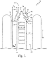
- FIG. 1 is a cross-sectional view of heat exchanger assembly 10 (shown in FIG. 2 ) in the vicinity of cold outlet face 12.
- Heat exchanger assembly 10 includes first fluid passages 14, defined by opposing first fluid passage walls 16, and first fluid diverters 18.
- First fluid diverters 18 are disposed between first fluid passage walls 16.
- Heat exchanger assembly 10 further includes second fluid passages 20, defined by opposing second fluid passage walls 22, and second fluid diverters 24.
- Second fluid diverters 24 are disposed between second fluid passage walls 22.
- second fluid diverters 24 are configured as fins, but in other embodiments, can be configured as pins, or a combination of fins and pins.
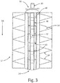
- First fluid passages 14 extend in direction D1 (shown in FIG. 3 ).
- Second fluid passages 20 extend in a direction D2.
- Direction D2 is generally perpendicular to direction D1.
- Ejector 26 is integrated into heat exchanger assembly 10.
- Ejector 26 includes integral ejector passage 28, which is a first fluid passage 14.
- Integral ejector passage 28 includes primary inlet 30 (shown in FIG. 3 ) and outlet nozzle 32.
- Ejector 26 further includes secondary inlet 34 and mixing section 36.
- Secondary inlet 34 is in fluid communication with a second fluid passage 20.
- Mixing section 36 is in fluid communication with outlet nozzle 32 and secondary inlet 34.
- outlet nozzle 32 is an opening, such as a slot.
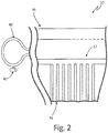
- FIG. 2 is a sectional view of heat exchanger assembly 10 taken along line A-A.
- Heat exchanger assembly 10 includes ejector 26, cold outlet face 12, heat exchanger 38, and manifold 40.
- Manifold 40 is configured to selectively introduce engine bleed air into ejector 26. Air flow into manifold 40 is controlled by ejector shutoff valve 42.
- ejector shutoff valve 42 is coupled to manifold 40. In other embodiments, ejector shutoff valve 42 can be attached directly to heat exchanger 38.
- manifold 40 introduces bleed air-a compressed, hot fluid-into integral ejector passage 28 through primary inlet 30. Thereafter, the hot fluid is ejected into mixing section 36 of ejector 26 through outlet nozzle 32. When the hot fluid is ejected, it creates an area of low pressure that draws fluid into the adjacent secondary inlet 34. Because secondary inlet 34 is in communication with second fluid passages 20, cold air is drawn into second fluid passages 20 at a cold inlet face (not shown) of heat exchanger 38. That is, the hot fluid serves as the motive fluid, and the cold fluid serves as the suction fluid for ejector 26. The cold fluid flows through second fluid passages 20 and exits at cold outlet face 12.
- mixing section 36 a portion of the cold fluid flow enters mixing section 36 through secondary inlet 34.
- the hot and cold fluids mix in mixing section 36to form an intermediate fluid.
- the intermediate fluid is expelled through a cold air outlet (not shown) of heat exchanger assembly 10, and can be routed overboard.
- Secondary inlet 34 communicates with a second fluid passage 20 via inlet passage 44.
- Inlet passage 44 is defined by inner wall 46 and outer wall 48.
- inner wall 46 converges near outlet nozzle 32.
- Outer wall 48 converges in a complementary manner to maintain generally even spacing from inner wall 46.
- Inner wall 46 and outer wall 48 are joined by a connector.
- the connector is gusset 50. In other embodiments, the connector can be another suitable connecting structure.
- integral ejector passage 28 extends from first fluid inlet end 52 to first fluid outlet end 54 of a first fluid passage 14.
- integral ejector passage 28 is a downstream first fluid passage 14.
- heat exchanger assembly 10 includes a plurality of ejectors 26 along cold outlet face 12 based on system requirements. Additionally, first and second fluid passage walls 16, 22 and diverters 18, 24, as well as the ejector 26, can be formed from aluminum. In other embodiments, other suitable materials can be used, including steel, nickel alloys, or titanium, or combinations of such materials.
- Heat exchanger assembly 10 can be manufactured by an additive manufacturing process such as, direct metal laser sintering (DMLS), laser net shape manufacturing (LNSM), electron beam manufacturing (EBM), or laminated object manufacturing (LOM), to name a few non-limiting examples.
- Additive manufacturing techniques can include, for example, forming a three-dimensional object through layer-by-layer construction of a plurality of thin sheets or material, or through powder bed infusion.
- Heat exchanger assembly 10 can be additively manufactured by forming a plurality of first and second fluid passage walls and diverters, which define a plurality of first and second fluid passages.
- An ejector is integrated into the heat exchanger assembly.
- the ejector includes an integral ejector passage, where the integral ejector passage is a first fluid passage, and where the integral ejector passage includes: a primary inlet configured to receive a hot fluid and an outlet nozzle configured to eject the hot fluid.
- the ejector further includes a secondary inlet configured to receive a cold fluid, where the secondary inlet is in fluid communication with a second fluid passage and a mixing section in fluid communication with the outlet nozzle of the integral ejector passage and the secondary inlet.
- the disclosed heat exchanger assembly provides a means of inducing cold air flow through the heat exchanger when other means, such as a fan or ram air, are unavailable. Forming the heat exchanger assembly using additive manufacturing eliminates the need for a separate ejector and additional coupling materials. It also allows the heat exchanger assembly to take up less space on the aircraft.
- a heat exchanger assembly includes a plurality of first and second fluid passages.
- the first fluid passages are defined by a pair of opposing first fluid passage walls and a plurality of first fluid diverters disposed between the first fluid passages walls.
- the second fluid passages are defined by a pair of opposing second fluid passage walls and a plurality of second fluid diverters disposed between the second fluid passage walls.
- An ejector is integrated into the heat exchanger assembly.
- the ejector includes an integral ejector passage, wherein the integral ejector passage is a first fluid passage, and wherein the integral ejector passage includes: a primary inlet configured to receive a hot fluid; and an outlet nozzle configured to eject the hot fluid.
- the ejector also includes a secondary inlet configured to receive a cold fluid, wherein the secondary inlet is in fluid communication with a second fluid passage; and a mixing section in fluid communication with the outlet nozzle of the integral ejector passage and the secondary inlet.
- the assembly of the preceding paragraph can optionally include, additionally and/or alternatively, any one or more of the following features, configurations and/or additional components:
- a manifold configured to introduce the hot fluid into the primary inlet.
- a further embodiment of any of the foregoing heat exchanger assemblies wherein the integral ejector passage comprises a first fluid inlet end and a first fluid outlet end, and wherein the ejector extends from the first fluid inlet end to the first fluid outlet end.
- inlet passage comprises an inner wall and an outer wall, and wherein the inner wall and outer wall are connected by a gusset.
- a method of making a heat exchanger includes: forming a plurality of opposing first fluid passage walls and a plurality of first fluid diverters disposed between the first fluid passages walls, wherein the plurality of first fluid passage walls and the plurality of first fluid diverters define a plurality of first fluid passages; forming a plurality of opposing second fluid passage walls and a plurality of second fluid diverters disposed between the second fluid passage walls, wherein the plurality of second fluid passage walls and the plurality of second fluid diverters define a plurality of second fluid passages; and integrating an ejector into the heat exchanger assembly.
- the ejector includes an integral ejector passage, wherein the integral ejector passage is a first fluid passage, and wherein the integral ejector passage includes: a primary inlet configured to receive a hot fluid; and an outlet nozzle configured to eject the hot fluid.
- the ejector also includes a secondary inlet configured to receive a cold fluid, wherein the secondary inlet is in fluid communication with a second fluid passage; and a mixing section in fluid communication with the outlet nozzle of the integral ejector passage and the secondary inlet.
- the method of the preceding paragraph can optionally include, additionally and/or alternatively, any one or more of the following features, configurations and/or additional components:
- the method includes extending the ejector from an inlet end to an outlet end of the integral ejector passage.
- the method includes forming an inlet passage having an inner wall and an outer wall.
- the method includes connecting the inner wall to the outer wall with a gusset.
- the method includes forming the heat exchanger assembly by additive manufacturing.
- the method includes forming the heat exchanger assembly from aluminum.
- the method includes forming the heat exchanger assembly from a material selected from the group consisting of steel, nickel alloys, titanium, and combinations thereof.
Landscapes
- Engineering & Computer Science (AREA)
- Mechanical Engineering (AREA)
- General Engineering & Computer Science (AREA)
- Physics & Mathematics (AREA)
- Thermal Sciences (AREA)
- Chemical & Material Sciences (AREA)
- Combustion & Propulsion (AREA)
- Fluid Mechanics (AREA)
- Transportation (AREA)
- Geometry (AREA)
- Heat-Exchange Devices With Radiators And Conduit Assemblies (AREA)
Abstract
Description
- During operation of a gas turbine powered aircraft, cold airflow can be introduced to a heat exchanger by a fan, or as ram air when the aircraft is in motion. However, when no fan is available, or when the aircraft is on the ground, engine bleed air can be used to induce a cooling air flow through the heat exchanger. In such cases, an ejector in flow communication with the heat exchanger serves to draw cold air into the heat exchanger.
- One problem with using an ejector, which is located separate from the heat exchanger, is that it requires additional materials to connect it in flow communication with the heat exchanger. It can also be difficult to fit both the ejector and the heat exchanger into the available space on an aircraft. Accordingly, there is a need for a heat exchanger and an ejector that, together, have a small footprint.
- A heat exchanger assembly includes a plurality of first and second fluid passages. The first fluid passages are defined by a pair of opposing first fluid passage walls and a plurality of first fluid diverters disposed between the first fluid passages walls. The second fluid passages are defined by a pair of opposing second fluid passage walls and a plurality of second fluid diverters disposed between the second fluid passage walls. An ejector is integrated into the heat exchanger assembly. The ejector includes an integral ejector passage, wherein the integral ejector passage is a first fluid passage, and wherein the integral ejector passage includes: a primary inlet configured to receive a hot fluid; and an outlet nozzle configured to eject the hot fluid. The ejector also includes a secondary inlet configured to receive a cold fluid, wherein the secondary inlet is in fluid communication with a second fluid passage; and a mixing section in fluid communication with the outlet nozzle of the integral ejector passage and the secondary inlet.
- A method of making a heat exchanger includes: forming a plurality of opposing first fluid passage walls and a plurality of first fluid diverters disposed between the first fluid passages walls, where the plurality of first fluid passage walls and the plurality of first fluid diverters define a plurality of first fluid passages; forming a plurality of opposing second fluid passage walls and a plurality of second fluid diverters disposed between the second fluid passage walls, where the plurality of second fluid passage walls and the plurality of second fluid diverters define a plurality of second fluid passages; and integrating an ejector into the heat exchanger assembly. The ejector includes an integral ejector passage, wherein the integral ejector passage is a first fluid passage, and wherein the integral ejector passage includes: a primary inlet configured to receive a hot fluid; and an outlet nozzle configured to eject the hot fluid. The ejector also includes a secondary inlet configured to receive a cold fluid, wherein the secondary inlet is in fluid communication with a second fluid passage; and a mixing section in fluid communication with the outlet nozzle of the integral ejector passage and the secondary inlet.
-
-
FIG. 1 is a cross-sectional view of a heat exchanger assembly. -
FIG. 2 is a sectional view of the heat exchanger assembly ofFIG 1 . -
FIG. 3 is a front view of a cold outlet face of the heat exchanger assembly ofFIG. 1 . - The disclosed heat exchanger assembly includes an integral bleed air ejector. Additive manufacturing is used to build the ejector into a hot fluid passage at the cold outlet end of the heat exchanger. The ejector is configured to draw air from adjacent cold air passages when in operation. The integral ejector requires less space and material than traditional ejectors that are separate from the heat exchanger.
-
FIG. 1 is a cross-sectional view of heat exchanger assembly 10 (shown inFIG. 2 ) in the vicinity ofcold outlet face 12.Heat exchanger assembly 10 includesfirst fluid passages 14, defined by opposing first fluid passage walls 16, and first fluid diverters 18.First fluid diverters 18 are disposed between first fluid passage walls 16.Heat exchanger assembly 10 further includessecond fluid passages 20, defined by opposing secondfluid passage walls 22, and second fluid diverters 24.Second fluid diverters 24 are disposed between secondfluid passage walls 22. In the embodiment shown,second fluid diverters 24 are configured as fins, but in other embodiments, can be configured as pins, or a combination of fins and pins. -
First fluid passages 14 extend in direction D1 (shown inFIG. 3 ).Second fluid passages 20 extend in a direction D2. Direction D2 is generally perpendicular to direction D1. -
Ejector 26 is integrated intoheat exchanger assembly 10.Ejector 26 includesintegral ejector passage 28, which is afirst fluid passage 14.Integral ejector passage 28 includes primary inlet 30 (shown inFIG. 3 ) andoutlet nozzle 32.Ejector 26 further includessecondary inlet 34 andmixing section 36.Secondary inlet 34 is in fluid communication with asecond fluid passage 20.Mixing section 36 is in fluid communication withoutlet nozzle 32 andsecondary inlet 34. In one embodiment,outlet nozzle 32 is an opening, such as a slot. -
FIG. 2 is a sectional view ofheat exchanger assembly 10 taken along line A-A.Heat exchanger assembly 10 includesejector 26,cold outlet face 12,heat exchanger 38, andmanifold 40. Manifold 40 is configured to selectively introduce engine bleed air intoejector 26. Air flow intomanifold 40 is controlled byejector shutoff valve 42. In one embodiment,ejector shutoff valve 42 is coupled tomanifold 40. In other embodiments,ejector shutoff valve 42 can be attached directly toheat exchanger 38. - In operation of the disclosed heat exchanger assembly,
manifold 40 introduces bleed air-a compressed, hot fluid-intointegral ejector passage 28 throughprimary inlet 30. Thereafter, the hot fluid is ejected intomixing section 36 ofejector 26 throughoutlet nozzle 32. When the hot fluid is ejected, it creates an area of low pressure that draws fluid into the adjacentsecondary inlet 34. Becausesecondary inlet 34 is in communication withsecond fluid passages 20, cold air is drawn intosecond fluid passages 20 at a cold inlet face (not shown) ofheat exchanger 38. That is, the hot fluid serves as the motive fluid, and the cold fluid serves as the suction fluid forejector 26. The cold fluid flows throughsecond fluid passages 20 and exits atcold outlet face 12. However, a portion of the cold fluid flow enters mixingsection 36 throughsecondary inlet 34. The hot and cold fluids mix in mixing section 36to form an intermediate fluid. The intermediate fluid is expelled through a cold air outlet (not shown) ofheat exchanger assembly 10, and can be routed overboard. -
Secondary inlet 34 communicates with asecond fluid passage 20 viainlet passage 44.Inlet passage 44 is defined byinner wall 46 andouter wall 48. In the embodiment shown inFIG. 1 ,inner wall 46 converges nearoutlet nozzle 32.Outer wall 48 converges in a complementary manner to maintain generally even spacing frominner wall 46.Inner wall 46 andouter wall 48 are joined by a connector. In one embodiment, the connector is gusset 50. In other embodiments, the connector can be another suitable connecting structure. - As shown in
FIG. 3 ,integral ejector passage 28 extends from firstfluid inlet end 52 to firstfluid outlet end 54 of afirst fluid passage 14. In the disclosed embodiment,integral ejector passage 28 is a downstreamfirst fluid passage 14. - In some embodiments,
heat exchanger assembly 10 includes a plurality ofejectors 26 alongcold outlet face 12 based on system requirements. Additionally, first and secondfluid passage walls 16, 22 anddiverters ejector 26, can be formed from aluminum. In other embodiments, other suitable materials can be used, including steel, nickel alloys, or titanium, or combinations of such materials. -
Heat exchanger assembly 10 can be manufactured by an additive manufacturing process such as, direct metal laser sintering (DMLS), laser net shape manufacturing (LNSM), electron beam manufacturing (EBM), or laminated object manufacturing (LOM), to name a few non-limiting examples. Additive manufacturing techniques can include, for example, forming a three-dimensional object through layer-by-layer construction of a plurality of thin sheets or material, or through powder bed infusion. -
Heat exchanger assembly 10 can be additively manufactured by forming a plurality of first and second fluid passage walls and diverters, which define a plurality of first and second fluid passages. An ejector is integrated into the heat exchanger assembly. The ejector includes an integral ejector passage, where the integral ejector passage is a first fluid passage, and where the integral ejector passage includes: a primary inlet configured to receive a hot fluid and an outlet nozzle configured to eject the hot fluid. The ejector further includes a secondary inlet configured to receive a cold fluid, where the secondary inlet is in fluid communication with a second fluid passage and a mixing section in fluid communication with the outlet nozzle of the integral ejector passage and the secondary inlet. - The disclosed heat exchanger assembly provides a means of inducing cold air flow through the heat exchanger when other means, such as a fan or ram air, are unavailable. Forming the heat exchanger assembly using additive manufacturing eliminates the need for a separate ejector and additional coupling materials. It also allows the heat exchanger assembly to take up less space on the aircraft.
- The following are non-exclusive descriptions of possible embodiments of the present invention.
- A heat exchanger assembly includes a plurality of first and second fluid passages. The first fluid passages are defined by a pair of opposing first fluid passage walls and a plurality of first fluid diverters disposed between the first fluid passages walls. The second fluid passages are defined by a pair of opposing second fluid passage walls and a plurality of second fluid diverters disposed between the second fluid passage walls. An ejector is integrated into the heat exchanger assembly. The ejector includes an integral ejector passage, wherein the integral ejector passage is a first fluid passage, and wherein the integral ejector passage includes: a primary inlet configured to receive a hot fluid; and an outlet nozzle configured to eject the hot fluid. The ejector also includes a secondary inlet configured to receive a cold fluid, wherein the secondary inlet is in fluid communication with a second fluid passage; and a mixing section in fluid communication with the outlet nozzle of the integral ejector passage and the secondary inlet.
- The assembly of the preceding paragraph can optionally include, additionally and/or alternatively, any one or more of the following features, configurations and/or additional components:
- A manifold configured to introduce the hot fluid into the primary inlet.
- A valve for selectively controlling the introduction of the hot fluid into the manifold.
- A further embodiment of any of the foregoing heat exchanger assemblies, wherein the integral ejector passage comprises a first fluid inlet end and a first fluid outlet end, and wherein the ejector extends from the first fluid inlet end to the first fluid outlet end.
- A further embodiment of any of the foregoing heat exchanger assemblies, wherein the integral ejector passage is a downstream first fluid passage.
- A further embodiment of any of the foregoing heat exchanger assemblies, wherein an inlet passage joins the secondary inlet to the second fluid passage.
- A further embodiment of any of the foregoing heat exchanger assemblies, wherein the inlet passage comprises an inner wall and an outer wall, and wherein the inner wall and outer wall are connected by a gusset.
- A further embodiment of any of the foregoing heat exchanger assemblies, wherein the plurality of first and second fluid passage walls and diverters are formed from aluminum.
- A further embodiment of any of the foregoing heat exchanger assemblies, wherein the plurality of first and second fluid passage walls and diverters are formed from a material selected from the group consisting of steel, nickel alloys, titanium, and combinations thereof.
- A method of making a heat exchanger includes: forming a plurality of opposing first fluid passage walls and a plurality of first fluid diverters disposed between the first fluid passages walls, wherein the plurality of first fluid passage walls and the plurality of first fluid diverters define a plurality of first fluid passages; forming a plurality of opposing second fluid passage walls and a plurality of second fluid diverters disposed between the second fluid passage walls, wherein the plurality of second fluid passage walls and the plurality of second fluid diverters define a plurality of second fluid passages; and integrating an ejector into the heat exchanger assembly. The ejector includes an integral ejector passage, wherein the integral ejector passage is a first fluid passage, and wherein the integral ejector passage includes: a primary inlet configured to receive a hot fluid; and an outlet nozzle configured to eject the hot fluid. The ejector also includes a secondary inlet configured to receive a cold fluid, wherein the secondary inlet is in fluid communication with a second fluid passage; and a mixing section in fluid communication with the outlet nozzle of the integral ejector passage and the secondary inlet.
- The method of the preceding paragraph can optionally include, additionally and/or alternatively, any one or more of the following features, configurations and/or additional components:
- The method includes extending the ejector from an inlet end to an outlet end of the integral ejector passage.
- The method includes forming an inlet passage having an inner wall and an outer wall.
- The method includes connecting the inner wall to the outer wall with a gusset.
- The method includes forming the heat exchanger assembly by additive manufacturing.
- The method includes forming the heat exchanger assembly from aluminum.
- The method includes forming the heat exchanger assembly from a material selected from the group consisting of steel, nickel alloys, titanium, and combinations thereof.
- While the invention has been described with reference to an exemplary embodiment(s), it will be understood by those skilled in the art that various changes may be made and equivalents may be substituted for elements thereof without departing from the scope of the invention. In addition, many modifications may be made to adapt a particular situation or material to the teachings of the invention without departing from the essential scope thereof. Therefore, it is intended that the invention not be limited to the particular embodiment(s) disclosed, but that the invention will include all embodiments falling within the scope of the appended claims.
Claims (15)
- A heat exchanger assembly (10) comprising:a plurality of first fluid passages (14), the plurality of first fluid passages (14) defined by:a pair of opposing first fluid passage walls (16); anda plurality of first fluid diverters disposed between the first fluid passage walls (16); anda plurality of second fluid passages (22), the plurality of second fluid passages defined by:a pair of opposing second fluid passage walls (22); anda plurality of second fluid diverters (24) disposed between the second fluid passage walls (22); andan ejector (26) integrated into the heat exchanger assembly (10), the ejector (26) comprising:an integral ejector passage (28), wherein the integral ejector passage (28) is a first fluid passage (14), and wherein the integral ejector passage (28) comprises:a primary inlet (30) configured to receive a hot fluid; andan outlet nozzle configured to eject the hot fluid;a secondary inlet (34) configured to receive a cold fluid, wherein the secondary inlet (34) is in fluid communication with a second fluid passage (20); anda mixing section (36) in fluid communication with the outlet nozzle (32) of the integral ejector passage (28) and the secondary inlet (34).
- The assembly of claim 1, further comprising: a manifold (40) configured to introduce the hot fluid into the primary inlet (30).
- The assembly of claim 1 or 2, further comprising: a valve for selectively controlling the introduction of the hot fluid into the manifold (40).
- The assembly of any preceding claim, wherein the integral ejector passage (28) comprises a first fluid inlet end (52) and a first fluid outlet end (54), and wherein the ejector extends from the first fluid inlet end (52) to the first fluid outlet end (54).
- The assembly of any preceding claim, wherein the integral ejector passage (28) is a downstream first fluid passage.
- The assembly of any preceding claim, wherein an inlet passage joins the secondary inlet (34) to the second fluid passage.
- The assembly of claim 6, wherein the secondary inlet passage comprises an inner wall and an outer wall, and wherein the inner wall and outer wall are connected by a gusset.
- The assembly of any preceding claim, wherein the plurality of first and second fluid passage walls and diverters are formed from aluminum.
- The assembly of any of claims 1 to 8, wherein the plurality of first and second fluid passage walls and diverters are formed from a material selected from the group consisting of steel, nickel alloys, titanium, and combinations thereof.
- A method of making a heat exchanger assembly (10) comprising:forming a plurality of opposing first fluid passage walls (16) and a plurality of first fluid diverters (18) disposed between the first fluid passage walls (16); wherein the plurality of first fluid passage walls (16) and the plurality of first fluid diverters (18) define a plurality of first fluid passages (14);forming a pair of opposing second fluid passage walls (22) and a plurality of second fluid diverters (24) disposed between the second fluid passage walls (22); wherein the plurality of second fluid passage walls (22) and the plurality of second fluid diverters (24) define a plurality of second fluid passages (22);integrating an ejector (26) into the heat exchanger assembly (10), the ejector (26) comprising:an integral ejector passage (28), wherein the integral ejector passage (28) is a first fluid passage (14), and wherein the integral ejector passage (28) comprises:a primary inlet (30) configured to receive a hot fluid; andan outlet nozzle (32) configured to eject the hot fluid;a secondary inlet (34) configured to receive a cold fluid, wherein the secondary inlet (34) is in fluid communication with a second fluid passage; anda mixing section (36) in fluid communication with the outlet nozzle (32) of the integral ejector passage and the secondary inlet.
- The method of claim 10, further comprising: extending the ejector (26) from an inlet end to an outlet end of the integral ejector passage (28).
- The method of claim 10 or 11, further comprising: forming an inlet passage having an inner wall and an outer wall.
- The method of claim 12, further comprising: connecting the inner wall to the outer wall with a gusset.
- The method of any of claims 10 to 13, further comprising: forming the heat exchanger assembly by additive manufacturing.
- The method of any of claims 10 to 14, further comprising: forming the heat exchanger assembly (10) from aluminum, or forming the heat exchanger from a material selected from the group consisting of steel, nickel alloys, titanium, and combinations thereof.
Applications Claiming Priority (1)
| Application Number | Priority Date | Filing Date | Title |
|---|---|---|---|
| US15/332,538 US10203159B2 (en) | 2016-10-24 | 2016-10-24 | Heat exchanger with integral bleed air ejector |
Publications (2)
| Publication Number | Publication Date |
|---|---|
| EP3312542A1 true EP3312542A1 (en) | 2018-04-25 |
| EP3312542B1 EP3312542B1 (en) | 2019-12-25 |
Family
ID=60182400
Family Applications (1)
| Application Number | Title | Priority Date | Filing Date |
|---|---|---|---|
| EP17197962.8A Active EP3312542B1 (en) | 2016-10-24 | 2017-10-24 | Heat exchanger with integral bleed air ejector |
Country Status (2)
| Country | Link |
|---|---|
| US (1) | US10203159B2 (en) |
| EP (1) | EP3312542B1 (en) |
Families Citing this family (2)
| Publication number | Priority date | Publication date | Assignee | Title |
|---|---|---|---|---|
| US11512639B2 (en) | 2021-01-26 | 2022-11-29 | General Electric Company | Heat transfer system |
| US11710902B2 (en) | 2021-02-09 | 2023-07-25 | International Business Machines Corporation | Dual-polarized magneto-electric antenna array |
Citations (4)
| Publication number | Priority date | Publication date | Assignee | Title |
|---|---|---|---|---|
| EP0255313A2 (en) * | 1986-07-29 | 1988-02-03 | Showa Aluminum Kabushiki Kaisha | Condenser |
| JP2014118103A (en) * | 2012-12-19 | 2014-06-30 | Calsonic Kansei Corp | Cooling fan device |
| JP2015001155A (en) * | 2013-06-13 | 2015-01-05 | カルソニックカンセイ株式会社 | Cooling device |
| JP2015124748A (en) * | 2013-12-27 | 2015-07-06 | カルソニックカンセイ株式会社 | Cooling device |
Family Cites Families (4)
| Publication number | Priority date | Publication date | Assignee | Title |
|---|---|---|---|---|
| US7175692B2 (en) * | 2004-06-21 | 2007-02-13 | Hamilton Sundstrand | Ejector to reduce permeate backpressure of air separation module |
| US20090288811A1 (en) * | 2008-05-20 | 2009-11-26 | Bolla James D | Aluminum plate-fin heat exchanger utilizing titanium separator plates |
| EP2577071B1 (en) * | 2010-06-01 | 2017-12-20 | Esg Mbh | Duct having a flow-guiding surface |
| US9458764B2 (en) * | 2012-11-26 | 2016-10-04 | Pratt & Whitney Canada Corp. | Air cooled air cooler for gas turbine engine air system |
-
2016
- 2016-10-24 US US15/332,538 patent/US10203159B2/en active Active
-
2017
- 2017-10-24 EP EP17197962.8A patent/EP3312542B1/en active Active
Patent Citations (4)
| Publication number | Priority date | Publication date | Assignee | Title |
|---|---|---|---|---|
| EP0255313A2 (en) * | 1986-07-29 | 1988-02-03 | Showa Aluminum Kabushiki Kaisha | Condenser |
| JP2014118103A (en) * | 2012-12-19 | 2014-06-30 | Calsonic Kansei Corp | Cooling fan device |
| JP2015001155A (en) * | 2013-06-13 | 2015-01-05 | カルソニックカンセイ株式会社 | Cooling device |
| JP2015124748A (en) * | 2013-12-27 | 2015-07-06 | カルソニックカンセイ株式会社 | Cooling device |
Also Published As
| Publication number | Publication date |
|---|---|
| US10203159B2 (en) | 2019-02-12 |
| EP3312542B1 (en) | 2019-12-25 |
| US20180112921A1 (en) | 2018-04-26 |
Similar Documents
| Publication | Publication Date | Title |
|---|---|---|
| US10100733B2 (en) | Turbine engine with anti-ice valve assembly, bleed air valve, and method of operating | |
| EP2562354A2 (en) | Cooling insert for a gas turbine engine airfoil | |
| US8628292B2 (en) | Eccentric chamfer at inlet of branches in a flow channel | |
| CN104364581B (en) | Gas-turbine unit wall | |
| EP3117169B1 (en) | Heat exchanger | |
| CN102596717B (en) | Flow body, in particular for aircraft | |
| US11454463B2 (en) | Fluid eductors, and systems and methods of entraining fluid using fluid eductors | |
| EP3312542B1 (en) | Heat exchanger with integral bleed air ejector | |
| US10458259B2 (en) | Engine component wall with a cooling circuit | |
| EP3173586A1 (en) | Engine component with film cooling | |
| US20170328212A1 (en) | Engine component wall with a cooling circuit | |
| US10072664B2 (en) | Debris filter for motor cooling inlet on ram air fan | |
| EP2995774B1 (en) | Gas turbine engine component, corresponding airfoil and gas turbine engine | |
| US10344598B2 (en) | Trailing edge cooling for a turbine blade | |
| US9435210B2 (en) | Cooled turbine blade for gas turbine engine | |
| US20150226072A1 (en) | Welded dual chamber impingement tube | |
| CN113260792B (en) | Jet fan and vehicle containing such a fan | |
| EP3628843A1 (en) | Fluid passage assembly for power generator | |
| CN105460222B (en) | Cockpit coupler for mixer | |
| EP2918957A1 (en) | Heat exchanger | |
| US20170328213A1 (en) | Engine component wall with a cooling circuit | |
| US11998974B2 (en) | Casting core for a cast engine component | |
| US10738700B2 (en) | Turbine assembly |
Legal Events
| Date | Code | Title | Description |
|---|---|---|---|
| PUAI | Public reference made under article 153(3) epc to a published international application that has entered the european phase |
Free format text: ORIGINAL CODE: 0009012 |
|
| STAA | Information on the status of an ep patent application or granted ep patent |
Free format text: STATUS: THE APPLICATION HAS BEEN PUBLISHED |
|
| AK | Designated contracting states |
Kind code of ref document: A1 Designated state(s): AL AT BE BG CH CY CZ DE DK EE ES FI FR GB GR HR HU IE IS IT LI LT LU LV MC MK MT NL NO PL PT RO RS SE SI SK SM TR |
|
| AX | Request for extension of the european patent |
Extension state: BA ME |
|
| STAA | Information on the status of an ep patent application or granted ep patent |
Free format text: STATUS: REQUEST FOR EXAMINATION WAS MADE |
|
| 17P | Request for examination filed |
Effective date: 20181025 |
|
| RBV | Designated contracting states (corrected) |
Designated state(s): AL AT BE BG CH CY CZ DE DK EE ES FI FR GB GR HR HU IE IS IT LI LT LU LV MC MK MT NL NO PL PT RO RS SE SI SK SM TR |
|
| RIC1 | Information provided on ipc code assigned before grant |
Ipc: F02C 7/12 20060101ALI20190603BHEP Ipc: F04F 5/14 20060101ALI20190603BHEP Ipc: B60K 11/04 20060101ALI20190603BHEP Ipc: F28F 1/02 20060101ALI20190603BHEP Ipc: F28F 13/06 20060101AFI20190603BHEP Ipc: F04F 5/46 20060101ALI20190603BHEP |
|
| GRAP | Despatch of communication of intention to grant a patent |
Free format text: ORIGINAL CODE: EPIDOSNIGR1 |
|
| STAA | Information on the status of an ep patent application or granted ep patent |
Free format text: STATUS: GRANT OF PATENT IS INTENDED |
|
| INTG | Intention to grant announced |
Effective date: 20190712 |
|
| RAP1 | Party data changed (applicant data changed or rights of an application transferred) |
Owner name: HAMILTON SUNDSTRAND CORPORATION |
|
| GRAS | Grant fee paid |
Free format text: ORIGINAL CODE: EPIDOSNIGR3 |
|
| GRAA | (expected) grant |
Free format text: ORIGINAL CODE: 0009210 |
|
| STAA | Information on the status of an ep patent application or granted ep patent |
Free format text: STATUS: THE PATENT HAS BEEN GRANTED |
|
| AK | Designated contracting states |
Kind code of ref document: B1 Designated state(s): AL AT BE BG CH CY CZ DE DK EE ES FI FR GB GR HR HU IE IS IT LI LT LU LV MC MK MT NL NO PL PT RO RS SE SI SK SM TR |
|
| REG | Reference to a national code |
Ref country code: GB Ref legal event code: FG4D |
|
| REG | Reference to a national code |
Ref country code: CH Ref legal event code: EP |
|
| REG | Reference to a national code |
Ref country code: AT Ref legal event code: REF Ref document number: 1217578 Country of ref document: AT Kind code of ref document: T Effective date: 20200115 |
|
| REG | Reference to a national code |
Ref country code: DE Ref legal event code: R096 Ref document number: 602017010049 Country of ref document: DE |
|
| REG | Reference to a national code |
Ref country code: IE Ref legal event code: FG4D |
|
| REG | Reference to a national code |
Ref country code: NL Ref legal event code: MP Effective date: 20191225 |
|
| PG25 | Lapsed in a contracting state [announced via postgrant information from national office to epo] |
Ref country code: LV Free format text: LAPSE BECAUSE OF FAILURE TO SUBMIT A TRANSLATION OF THE DESCRIPTION OR TO PAY THE FEE WITHIN THE PRESCRIBED TIME-LIMIT Effective date: 20191225 Ref country code: SE Free format text: LAPSE BECAUSE OF FAILURE TO SUBMIT A TRANSLATION OF THE DESCRIPTION OR TO PAY THE FEE WITHIN THE PRESCRIBED TIME-LIMIT Effective date: 20191225 Ref country code: FI Free format text: LAPSE BECAUSE OF FAILURE TO SUBMIT A TRANSLATION OF THE DESCRIPTION OR TO PAY THE FEE WITHIN THE PRESCRIBED TIME-LIMIT Effective date: 20191225 Ref country code: GR Free format text: LAPSE BECAUSE OF FAILURE TO SUBMIT A TRANSLATION OF THE DESCRIPTION OR TO PAY THE FEE WITHIN THE PRESCRIBED TIME-LIMIT Effective date: 20200326 Ref country code: LT Free format text: LAPSE BECAUSE OF FAILURE TO SUBMIT A TRANSLATION OF THE DESCRIPTION OR TO PAY THE FEE WITHIN THE PRESCRIBED TIME-LIMIT Effective date: 20191225 Ref country code: NO Free format text: LAPSE BECAUSE OF FAILURE TO SUBMIT A TRANSLATION OF THE DESCRIPTION OR TO PAY THE FEE WITHIN THE PRESCRIBED TIME-LIMIT Effective date: 20200325 Ref country code: BG Free format text: LAPSE BECAUSE OF FAILURE TO SUBMIT A TRANSLATION OF THE DESCRIPTION OR TO PAY THE FEE WITHIN THE PRESCRIBED TIME-LIMIT Effective date: 20200325 |
|
| REG | Reference to a national code |
Ref country code: LT Ref legal event code: MG4D |
|
| PG25 | Lapsed in a contracting state [announced via postgrant information from national office to epo] |
Ref country code: HR Free format text: LAPSE BECAUSE OF FAILURE TO SUBMIT A TRANSLATION OF THE DESCRIPTION OR TO PAY THE FEE WITHIN THE PRESCRIBED TIME-LIMIT Effective date: 20191225 Ref country code: RS Free format text: LAPSE BECAUSE OF FAILURE TO SUBMIT A TRANSLATION OF THE DESCRIPTION OR TO PAY THE FEE WITHIN THE PRESCRIBED TIME-LIMIT Effective date: 20191225 |
|
| PG25 | Lapsed in a contracting state [announced via postgrant information from national office to epo] |
Ref country code: AL Free format text: LAPSE BECAUSE OF FAILURE TO SUBMIT A TRANSLATION OF THE DESCRIPTION OR TO PAY THE FEE WITHIN THE PRESCRIBED TIME-LIMIT Effective date: 20191225 |
|
| PG25 | Lapsed in a contracting state [announced via postgrant information from national office to epo] |
Ref country code: EE Free format text: LAPSE BECAUSE OF FAILURE TO SUBMIT A TRANSLATION OF THE DESCRIPTION OR TO PAY THE FEE WITHIN THE PRESCRIBED TIME-LIMIT Effective date: 20191225 Ref country code: CZ Free format text: LAPSE BECAUSE OF FAILURE TO SUBMIT A TRANSLATION OF THE DESCRIPTION OR TO PAY THE FEE WITHIN THE PRESCRIBED TIME-LIMIT Effective date: 20191225 Ref country code: NL Free format text: LAPSE BECAUSE OF FAILURE TO SUBMIT A TRANSLATION OF THE DESCRIPTION OR TO PAY THE FEE WITHIN THE PRESCRIBED TIME-LIMIT Effective date: 20191225 Ref country code: RO Free format text: LAPSE BECAUSE OF FAILURE TO SUBMIT A TRANSLATION OF THE DESCRIPTION OR TO PAY THE FEE WITHIN THE PRESCRIBED TIME-LIMIT Effective date: 20191225 Ref country code: PT Free format text: LAPSE BECAUSE OF FAILURE TO SUBMIT A TRANSLATION OF THE DESCRIPTION OR TO PAY THE FEE WITHIN THE PRESCRIBED TIME-LIMIT Effective date: 20200520 |
|
| PG25 | Lapsed in a contracting state [announced via postgrant information from national office to epo] |
Ref country code: SM Free format text: LAPSE BECAUSE OF FAILURE TO SUBMIT A TRANSLATION OF THE DESCRIPTION OR TO PAY THE FEE WITHIN THE PRESCRIBED TIME-LIMIT Effective date: 20191225 Ref country code: IS Free format text: LAPSE BECAUSE OF FAILURE TO SUBMIT A TRANSLATION OF THE DESCRIPTION OR TO PAY THE FEE WITHIN THE PRESCRIBED TIME-LIMIT Effective date: 20200425 Ref country code: SK Free format text: LAPSE BECAUSE OF FAILURE TO SUBMIT A TRANSLATION OF THE DESCRIPTION OR TO PAY THE FEE WITHIN THE PRESCRIBED TIME-LIMIT Effective date: 20191225 |
|
| REG | Reference to a national code |
Ref country code: DE Ref legal event code: R097 Ref document number: 602017010049 Country of ref document: DE |
|
| PG25 | Lapsed in a contracting state [announced via postgrant information from national office to epo] |
Ref country code: ES Free format text: LAPSE BECAUSE OF FAILURE TO SUBMIT A TRANSLATION OF THE DESCRIPTION OR TO PAY THE FEE WITHIN THE PRESCRIBED TIME-LIMIT Effective date: 20191225 Ref country code: DK Free format text: LAPSE BECAUSE OF FAILURE TO SUBMIT A TRANSLATION OF THE DESCRIPTION OR TO PAY THE FEE WITHIN THE PRESCRIBED TIME-LIMIT Effective date: 20191225 |
|
| PLBE | No opposition filed within time limit |
Free format text: ORIGINAL CODE: 0009261 |
|
| STAA | Information on the status of an ep patent application or granted ep patent |
Free format text: STATUS: NO OPPOSITION FILED WITHIN TIME LIMIT |
|
| REG | Reference to a national code |
Ref country code: AT Ref legal event code: MK05 Ref document number: 1217578 Country of ref document: AT Kind code of ref document: T Effective date: 20191225 |
|
| PG25 | Lapsed in a contracting state [announced via postgrant information from national office to epo] |
Ref country code: SI Free format text: LAPSE BECAUSE OF FAILURE TO SUBMIT A TRANSLATION OF THE DESCRIPTION OR TO PAY THE FEE WITHIN THE PRESCRIBED TIME-LIMIT Effective date: 20191225 |
|
| 26N | No opposition filed |
Effective date: 20200928 |
|
| PG25 | Lapsed in a contracting state [announced via postgrant information from national office to epo] |
Ref country code: AT Free format text: LAPSE BECAUSE OF FAILURE TO SUBMIT A TRANSLATION OF THE DESCRIPTION OR TO PAY THE FEE WITHIN THE PRESCRIBED TIME-LIMIT Effective date: 20191225 Ref country code: IT Free format text: LAPSE BECAUSE OF FAILURE TO SUBMIT A TRANSLATION OF THE DESCRIPTION OR TO PAY THE FEE WITHIN THE PRESCRIBED TIME-LIMIT Effective date: 20191225 |
|
| PG25 | Lapsed in a contracting state [announced via postgrant information from national office to epo] |
Ref country code: PL Free format text: LAPSE BECAUSE OF FAILURE TO SUBMIT A TRANSLATION OF THE DESCRIPTION OR TO PAY THE FEE WITHIN THE PRESCRIBED TIME-LIMIT Effective date: 20191225 |
|
| REG | Reference to a national code |
Ref country code: CH Ref legal event code: PL |
|
| PG25 | Lapsed in a contracting state [announced via postgrant information from national office to epo] |
Ref country code: LU Free format text: LAPSE BECAUSE OF NON-PAYMENT OF DUE FEES Effective date: 20201024 Ref country code: MC Free format text: LAPSE BECAUSE OF FAILURE TO SUBMIT A TRANSLATION OF THE DESCRIPTION OR TO PAY THE FEE WITHIN THE PRESCRIBED TIME-LIMIT Effective date: 20191225 |
|
| REG | Reference to a national code |
Ref country code: BE Ref legal event code: MM Effective date: 20201031 |
|
| PG25 | Lapsed in a contracting state [announced via postgrant information from national office to epo] |
Ref country code: BE Free format text: LAPSE BECAUSE OF NON-PAYMENT OF DUE FEES Effective date: 20201031 Ref country code: CH Free format text: LAPSE BECAUSE OF NON-PAYMENT OF DUE FEES Effective date: 20201031 Ref country code: LI Free format text: LAPSE BECAUSE OF NON-PAYMENT OF DUE FEES Effective date: 20201031 |
|
| PG25 | Lapsed in a contracting state [announced via postgrant information from national office to epo] |
Ref country code: IE Free format text: LAPSE BECAUSE OF NON-PAYMENT OF DUE FEES Effective date: 20201024 |
|
| PG25 | Lapsed in a contracting state [announced via postgrant information from national office to epo] |
Ref country code: TR Free format text: LAPSE BECAUSE OF FAILURE TO SUBMIT A TRANSLATION OF THE DESCRIPTION OR TO PAY THE FEE WITHIN THE PRESCRIBED TIME-LIMIT Effective date: 20191225 Ref country code: MT Free format text: LAPSE BECAUSE OF FAILURE TO SUBMIT A TRANSLATION OF THE DESCRIPTION OR TO PAY THE FEE WITHIN THE PRESCRIBED TIME-LIMIT Effective date: 20191225 Ref country code: CY Free format text: LAPSE BECAUSE OF FAILURE TO SUBMIT A TRANSLATION OF THE DESCRIPTION OR TO PAY THE FEE WITHIN THE PRESCRIBED TIME-LIMIT Effective date: 20191225 |
|
| PG25 | Lapsed in a contracting state [announced via postgrant information from national office to epo] |
Ref country code: MK Free format text: LAPSE BECAUSE OF FAILURE TO SUBMIT A TRANSLATION OF THE DESCRIPTION OR TO PAY THE FEE WITHIN THE PRESCRIBED TIME-LIMIT Effective date: 20191225 |
|
| P01 | Opt-out of the competence of the unified patent court (upc) registered |
Effective date: 20230522 |
|
| PGFP | Annual fee paid to national office [announced via postgrant information from national office to epo] |
Ref country code: GB Payment date: 20250923 Year of fee payment: 9 |
|
| PGFP | Annual fee paid to national office [announced via postgrant information from national office to epo] |
Ref country code: FR Payment date: 20250924 Year of fee payment: 9 |
|
| PGFP | Annual fee paid to national office [announced via postgrant information from national office to epo] |
Ref country code: DE Payment date: 20250923 Year of fee payment: 9 |