EP3312484A1 - Schaltventil mit aufpralldämpfung - Google Patents
Schaltventil mit aufpralldämpfung Download PDFInfo
- Publication number
- EP3312484A1 EP3312484A1 EP17196852.2A EP17196852A EP3312484A1 EP 3312484 A1 EP3312484 A1 EP 3312484A1 EP 17196852 A EP17196852 A EP 17196852A EP 3312484 A1 EP3312484 A1 EP 3312484A1
- Authority
- EP
- European Patent Office
- Prior art keywords
- valve
- armature
- volume
- movable assembly
- magnet armature
- Prior art date
- Legal status (The legal status is an assumption and is not a legal conclusion. Google has not performed a legal analysis and makes no representation as to the accuracy of the status listed.)
- Granted
Links
Images


Classifications
-
- F—MECHANICAL ENGINEERING; LIGHTING; HEATING; WEAPONS; BLASTING
- F16—ENGINEERING ELEMENTS AND UNITS; GENERAL MEASURES FOR PRODUCING AND MAINTAINING EFFECTIVE FUNCTIONING OF MACHINES OR INSTALLATIONS; THERMAL INSULATION IN GENERAL
- F16K—VALVES; TAPS; COCKS; ACTUATING-FLOATS; DEVICES FOR VENTING OR AERATING
- F16K31/00—Actuating devices; Operating means; Releasing devices
- F16K31/02—Actuating devices; Operating means; Releasing devices electric; magnetic
- F16K31/06—Actuating devices; Operating means; Releasing devices electric; magnetic using a magnet, e.g. diaphragm valves, cutting off by means of a liquid
- F16K31/0686—Braking, pressure equilibration, shock absorbing
- F16K31/0689—Braking of the valve element
-
- B—PERFORMING OPERATIONS; TRANSPORTING
- B60—VEHICLES IN GENERAL
- B60T—VEHICLE BRAKE CONTROL SYSTEMS OR PARTS THEREOF; BRAKE CONTROL SYSTEMS OR PARTS THEREOF, IN GENERAL; ARRANGEMENT OF BRAKING ELEMENTS ON VEHICLES IN GENERAL; PORTABLE DEVICES FOR PREVENTING UNWANTED MOVEMENT OF VEHICLES; VEHICLE MODIFICATIONS TO FACILITATE COOLING OF BRAKES
- B60T8/00—Arrangements for adjusting wheel-braking force to meet varying vehicular or ground-surface conditions, e.g. limiting or varying distribution of braking force
- B60T8/32—Arrangements for adjusting wheel-braking force to meet varying vehicular or ground-surface conditions, e.g. limiting or varying distribution of braking force responsive to a speed condition, e.g. acceleration or deceleration
- B60T8/34—Arrangements for adjusting wheel-braking force to meet varying vehicular or ground-surface conditions, e.g. limiting or varying distribution of braking force responsive to a speed condition, e.g. acceleration or deceleration having a fluid pressure regulator responsive to a speed condition
- B60T8/36—Arrangements for adjusting wheel-braking force to meet varying vehicular or ground-surface conditions, e.g. limiting or varying distribution of braking force responsive to a speed condition, e.g. acceleration or deceleration having a fluid pressure regulator responsive to a speed condition including a pilot valve responding to an electromagnetic force
- B60T8/3615—Electromagnetic valves specially adapted for anti-lock brake and traction control systems
- B60T8/363—Electromagnetic valves specially adapted for anti-lock brake and traction control systems in hydraulic systems
- B60T8/365—Electromagnetic valves specially adapted for anti-lock brake and traction control systems in hydraulic systems combining a plurality of functions in one unit, e.g. pressure relief
-
- F—MECHANICAL ENGINEERING; LIGHTING; HEATING; WEAPONS; BLASTING
- F16—ENGINEERING ELEMENTS AND UNITS; GENERAL MEASURES FOR PRODUCING AND MAINTAINING EFFECTIVE FUNCTIONING OF MACHINES OR INSTALLATIONS; THERMAL INSULATION IN GENERAL
- F16F—SPRINGS; SHOCK-ABSORBERS; MEANS FOR DAMPING VIBRATION
- F16F9/00—Springs, vibration-dampers, shock-absorbers, or similarly-constructed movement-dampers using a fluid or the equivalent as damping medium
- F16F9/32—Details
- F16F9/34—Special valve constructions; Shape or construction of throttling passages
-
- F—MECHANICAL ENGINEERING; LIGHTING; HEATING; WEAPONS; BLASTING
- F16—ENGINEERING ELEMENTS AND UNITS; GENERAL MEASURES FOR PRODUCING AND MAINTAINING EFFECTIVE FUNCTIONING OF MACHINES OR INSTALLATIONS; THERMAL INSULATION IN GENERAL
- F16K—VALVES; TAPS; COCKS; ACTUATING-FLOATS; DEVICES FOR VENTING OR AERATING
- F16K1/00—Lift valves or globe valves, i.e. cut-off apparatus with closure members having at least a component of their opening and closing motion perpendicular to the closing faces
- F16K1/32—Details
- F16K1/34—Cutting-off parts, e.g. valve members, seats
- F16K1/46—Attachment of sealing rings
-
- F—MECHANICAL ENGINEERING; LIGHTING; HEATING; WEAPONS; BLASTING
- F16—ENGINEERING ELEMENTS AND UNITS; GENERAL MEASURES FOR PRODUCING AND MAINTAINING EFFECTIVE FUNCTIONING OF MACHINES OR INSTALLATIONS; THERMAL INSULATION IN GENERAL
- F16K—VALVES; TAPS; COCKS; ACTUATING-FLOATS; DEVICES FOR VENTING OR AERATING
- F16K31/00—Actuating devices; Operating means; Releasing devices
- F16K31/02—Actuating devices; Operating means; Releasing devices electric; magnetic
- F16K31/06—Actuating devices; Operating means; Releasing devices electric; magnetic using a magnet, e.g. diaphragm valves, cutting off by means of a liquid
- F16K31/0644—One-way valve
- F16K31/0655—Lift valves
-
- F—MECHANICAL ENGINEERING; LIGHTING; HEATING; WEAPONS; BLASTING
- F16—ENGINEERING ELEMENTS AND UNITS; GENERAL MEASURES FOR PRODUCING AND MAINTAINING EFFECTIVE FUNCTIONING OF MACHINES OR INSTALLATIONS; THERMAL INSULATION IN GENERAL
- F16K—VALVES; TAPS; COCKS; ACTUATING-FLOATS; DEVICES FOR VENTING OR AERATING
- F16K31/00—Actuating devices; Operating means; Releasing devices
- F16K31/02—Actuating devices; Operating means; Releasing devices electric; magnetic
- F16K31/06—Actuating devices; Operating means; Releasing devices electric; magnetic using a magnet, e.g. diaphragm valves, cutting off by means of a liquid
- F16K31/0686—Braking, pressure equilibration, shock absorbing
- F16K31/0696—Shock absorbing, e.g. using a dash-pot
-
- F—MECHANICAL ENGINEERING; LIGHTING; HEATING; WEAPONS; BLASTING
- F16—ENGINEERING ELEMENTS AND UNITS; GENERAL MEASURES FOR PRODUCING AND MAINTAINING EFFECTIVE FUNCTIONING OF MACHINES OR INSTALLATIONS; THERMAL INSULATION IN GENERAL
- F16K—VALVES; TAPS; COCKS; ACTUATING-FLOATS; DEVICES FOR VENTING OR AERATING
- F16K47/00—Means in valves for absorbing fluid energy
- F16K47/04—Means in valves for absorbing fluid energy for decreasing pressure or noise level, the throttle being incorporated in the closure member
-
- H—ELECTRICITY
- H01—ELECTRIC ELEMENTS
- H01F—MAGNETS; INDUCTANCES; TRANSFORMERS; SELECTION OF MATERIALS FOR THEIR MAGNETIC PROPERTIES
- H01F7/00—Magnets
- H01F7/06—Electromagnets; Actuators including electromagnets
- H01F7/08—Electromagnets; Actuators including electromagnets with armatures
-
- F—MECHANICAL ENGINEERING; LIGHTING; HEATING; WEAPONS; BLASTING
- F16—ENGINEERING ELEMENTS AND UNITS; GENERAL MEASURES FOR PRODUCING AND MAINTAINING EFFECTIVE FUNCTIONING OF MACHINES OR INSTALLATIONS; THERMAL INSULATION IN GENERAL
- F16F—SPRINGS; SHOCK-ABSORBERS; MEANS FOR DAMPING VIBRATION
- F16F9/00—Springs, vibration-dampers, shock-absorbers, or similarly-constructed movement-dampers using a fluid or the equivalent as damping medium
- F16F9/32—Details
- F16F9/44—Means on or in the damper for manual or non-automatic adjustment; such means combined with temperature correction
- F16F9/46—Means on or in the damper for manual or non-automatic adjustment; such means combined with temperature correction allowing control from a distance, i.e. location of means for control input being remote from site of valves, e.g. on damper external wall
- F16F9/466—Throttling control, i.e. regulation of flow passage geometry
- F16F9/469—Valves incorporated in the piston
-
- F—MECHANICAL ENGINEERING; LIGHTING; HEATING; WEAPONS; BLASTING
- F16—ENGINEERING ELEMENTS AND UNITS; GENERAL MEASURES FOR PRODUCING AND MAINTAINING EFFECTIVE FUNCTIONING OF MACHINES OR INSTALLATIONS; THERMAL INSULATION IN GENERAL
- F16F—SPRINGS; SHOCK-ABSORBERS; MEANS FOR DAMPING VIBRATION
- F16F9/00—Springs, vibration-dampers, shock-absorbers, or similarly-constructed movement-dampers using a fluid or the equivalent as damping medium
- F16F9/32—Details
- F16F9/50—Special means providing automatic damping adjustment, i.e. self-adjustment of damping by particular sliding movements of a valve element, other than flexions or displacement of valve discs; Special means providing self-adjustment of spring characteristics
Definitions
- the present invention relates to an electrically or electromagnetically actuated valve, in particular for use in air spring systems of motor vehicles.
- Electrically or electromagnetically actuated switching valves include, inter alia, the components described in more detail below.
- a valve comprises a movable assembly with a magnetic armature which is movable in a valve sleeve along an axis, wherein in a first position at least one flow is released, which is locked in the second position.
- the armature is coupled to a sealing element which cooperates with a valve seat. The armature is moved by energizing a coil which surrounds the valve sleeve.
- Valves of the aforementioned type are used for a variety of purposes. They are used for example in air suspension systems of motor vehicles in various ways and for various functions. There are, for example, valves for filling and emptying the bellows, valves for connecting or locking of storage in the system, as well as valves, via which the bellows volumes can be connected with additional volume if necessary. Preferably, such valves are actuated electromagnetically, so also in the DE 10 2011078102 A1 described seat valve.
- Object of the present invention is therefore to propose a valve which has a high flow area with a fast switching time and is acoustically unobtrusive.
- the armature which is part of the movable assembly of the valve, defines in the valve sleeve a first volume on a first axial side of the armature and a second volume on a first axial side opposite the second axial side of the armature.
- the valve includes a radially resilient restriction member disposed between the first and second volumes such that it throttles fluid flow between the first and second volumes upon axial movement of the movable assembly.
- the movable assembly Due to the throttling and the compression of the air, the movable assembly is slowed down only towards the end of the movement just before the impact, which increases the current required to move the movable assembly only slightly.
- the movable assembly is stationary, preferably a pressure equalization between the two volumes.
- the throttle element comprises at least one circumferential seal, such as a ring seal, in a gap between the armature and the valve sleeve.
- the throttle element is contained in the movable assembly, in particular arranged along a circumference of the magnet armature, for example in a circumferential groove in the armature.
- the throttle element may alternatively or optionally additionally also be arranged in the stationary part of the valve, in particular in the valve sleeve. It can also be provided a plurality of throttle elements, which are arranged in the axial direction successively on the circumference of the armature and / or in the valve sleeve.
- At least one passage is provided, which allows a fluid flow between the first and second volume during axial movement of the movable assembly.
- the throttle element comprises a seal, such as a circumferential ring seal, which seals the first and the second volume against each other and a fluid flow, ie a pressure equalization between the two volumes in Substantially completely prevented. Since the braking effect may be too high in this case, it is advantageous to reduce the throttle effect by a corresponding passage.
- the passage is preferably arranged in the throttle element. It may for example comprise at least one slot in the peripheral seal, which may also be advantageous for the mounting of the throttle element on the circumference of the armature.
- a plurality of passages or differently configured passages or openings may be provided.
- at least one passage may also be provided in the magnet armature, which connects the first and second volumes to one another for pressure equalization. If at least one passage is formed in the magnet armature, the seal can be circumferentially completely closed.
- the throttle element is arranged and designed such that it develops a greater throttling effect in a first axial direction when moving the movable assembly than in a movement of the movable assembly in a second axial direction opposite to the first axial direction.
- the throttling action in the second axial direction of movement may, for example, be less than half, less than one third, or even less than 10% of the throttling effect in the first direction of movement.
- the throttle element preferably has substantially no throttling effect.
- the throttle element when switching on the valve, ie when energizing the coil, has a high throttle effect, since here the movable assembly is moved at a high speed to allow a short switching time. A sound through an undamped impact would therefore be particularly large when you turn on.
- the throttle effect can be low or completely eliminated.
- the throttle element may comprise at least one sealing lip, for example a sealing lip with a V-profile, which is open in an axial direction.
- a seal is also called V-seal or V-ring.
- the V-profile of the sealing lip is aligned such that the sealing lip at a generated by energizing the valve axial movement of the movable assembly, i. when switching on the valve, spreads.
- V-profile of the sealing lip can fold, so that in this direction of movement a smaller or substantially no throttle effect is generated by the throttle element.
- the term "V-profile” generally includes profiles with at least two legs that allow a spreading of the profile, such as U-shaped profiles.
- the throttle element may comprise, for example, PTFE or other suitable plastics
- the movable assembly may comprise a plunger which extends in the axial direction from the second axial side of the armature and through a bore in a stationary part of the valve.
- a seal can be arranged in the bore, which seals the second volume.
- the second axial side may in particular be that side of the magnet armature which lies forward in the direction of movement when the valve is switched on, in other words, that side of the magnet armature which limits the volume in which an overpressure builds up to decelerate the movement of the movable module , as described above. In order to increase the structure of the overpressure and thus the throttle effect, it is advantageous to seal this volume.
- This seal can For example, comprise a sealing sleeve in which the plunger is movably mounted.
- the sealing sleeve can be movably mounted in the bore. It forms a very small gap with the plunger so that the desired throttling is achieved. It is understood that other seals are also possible that may be located in the bore and / or on the plunger, such as one or more ring seals.
- the magnet armature may comprise at least one recess on one axial side, wherein the recess preferably occupies more than a third, more preferably more than half of a cross-sectional area of the magnet armature.
- damper elements in particular in the region of a stop of the armature can be provided, for example, damper elements as in the seat valve DE 10 2011078102 A1 ,
- the flow through the valve may include at least one axial flow opening at one end and, for example, at least one radial flow opening at another end, the closure element effecting sealing of the at least one axial flow opening in the second position.
- the valve is a poppet valve, but the invention is also advantageously applicable to other types of valves, such as spool valves.
- a single or several of the above-described valves can be advantageously used in an air spring system of a motor vehicle.
- electromagnetically actuated switching valve 1 has a valve opening 2 with a sealing seat 3, which is closable by a sealing element 4.
- the valve 1 is therefore designed as a seat valve.
- the sealing surface of the sealing element 4 is elastically deformable in order to ensure a reliable sealing of the axial flow opening 2.
- the sealing element 4 is seated at the front axial end of a valve element 5, which is coupled via a plunger 6 with a movable armature 7. It is in principle conceivable to fasten the sealing element 4 directly on the magnet armature 7. In the illustrated embodiment, however, the valve member 5 sits firmly on the plunger 6, which in turn sits firmly in the armature 7.
- valve element 5 and the plunger 6 or the armature 7 and the plunger 6 are in particular pressed together. This allows when mounting the adjustment of the length of the movable assembly and the axial distance of the armature 7 to the pole piece 8.
- the valve element 5 is mounted by means of a dynamic seal 14 axially displaceable and sealed.
- the plunger 6 passes through a bore 23 in the pole part eighth
- the movable magnet armature 7 is part of an iron circle, to which the stationary pole part 8 belongs.
- the magnet armature 7 is axially displaceably mounted in a valve sleeve 22, separated by a gap 21.
- a volume 13 Between the magnet armature 7 and the pole part 8 is a volume 13, which allows the magnet armature 7 to move axially in the direction of the pole part 8, if the Sealing element 4 in his in Fig. 2 shown closed position is brought.
- On the axially opposite side of the armature 7 is a volume 12, which is a movement of the armature 7 of the in Fig. 2 shown locked state in the in Fig. 1 shown opened state allowed.
- the volumes 12 and 13 are bounded by the valve sleeve 22 and are interconnected by the gap 21, so that when axial movement of the armature 7 air between the two volumes 12 and 13 can be replaced.
- the armature 7 is held by mechanical load by means of a spring member 10 spaced from the pole piece 8.
- a magnet armature 7 and the pole part 8 surrounding coil 11 By electrical energization of a magnet armature 7 and the pole part 8 surrounding coil 11, a magnet armature 7 and the pole member 8 enforcing magnetic circuit is generated in such a way that between the pole member 8 and the magnet armature 7, a magnetic attraction acts, the mechanical loading of the spring element 10 counteracts and overcomes this.
- the magnet armature 7 then moves toward the pole part 8, so that the tappet 6 is displaced axially and the sealing element 4 closes the sealing seat 3, so that in the locked state, the flow between radial flow openings 17 a, 17 b and the axial flow opening 2 is prevented.
- the movable assembly In order to achieve a short switching time, in particular when closing the valve, the movable assembly is moved at a high speed. An undamped impact of the sealing element 4 on the sealing seat 3 would generate a disturbing noise, which can not be completely avoided even by damper elements (not shown), for example between the magnet armature 7 and the pole part 8.
- damper elements for example between the magnet armature 7 and the pole part 8.
- a minimum of the volume 13 in the form of an air gap is maintained between the pole part 8 and the magnet armature 7, so that an impact sound can be prevented at this point.
- the air gap increases the current at which the valve 1 opens, reducing the turn-off time. Short switching times in conjunction with high flow rates are particularly desired when using the valve 1 in an air spring system of a motor vehicle.
- a throttle element 9 which throttles the exchange of air between the two volumes 12 and 13.
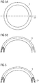
- the throttle element 9 is designed in particular as a V-seal, ie a sealing ring with a V-profile, as in Fig. 5A in a plan view and in Fig. 5B in a perspective sectional view (section along the dashed line in Fig. 5A ).
- the volume 13 is reduced in size and air contained therein is compressed (overpressure) and at the same time the volume 12 is increased and air contained therein expands (negative pressure).
- the volume 13 is sealed in the region of the plunger 6.
- a sealing sleeve 15 is inserted in the bore 23.
- the sealing sleeve 15 reduces the gap between the plunger 6 and the pole part 8 in the bore 23.
- the resulting small gap between the sealing sleeve 15 and the plunger 6 improves the throttling and braking of the movable assembly, since the volume 13 is then sealed on both sides.
- the throttle element 9 When switching on the valve 1, the throttle element 9 ensures that an exchange of air from the volume 13 in the direction of the volume 12 is throttled. Due to the orientation of the V-profile, i. the opening of the V-profile in the direction of the volume 13, an elastic deformation of the throttle element 9 takes place radially outward such that the V-profile spreads in an axial movement of the armature 7 in the direction of the pole piece 8 and against the inner wall of the valve sleeve 22 applies. As a result, the sealing effect is enhanced.
- the throttle element 9 has a slot 20 (FIG. Fig. 5A ).
- the slot 20 allows easy mounting of the otherwise annular throttle element 9 in the groove 19 of the magnet armature 7. It can also have multiple slots and / or one or more other through holes in the throttle element 9 or in the armature 7 and / or the plunger. 6 be provided, which allow an exchange of air between the two volumes 12 and 13.
- a throttle element 9 is shown with a hole 24 instead of a slot which extends through the throttle element 9, to allow an exchange of air through the throttle element 9 therethrough.
- Fig. 3 is a further embodiment of a valve 1 is shown, which is substantially similar to the valve 1 described above.
- the armature 7 is, however, formed in two parts. After insertion of the sealing ring 9, an annular member 16 is connected to the body of the armature 7, whereby the first open in the axial direction of the groove 19 is closed. Slitting the sealing ring 9 can be omitted.
- the provision of a slot 20 or other passage connecting the two volumes 12 and 13 together may nevertheless be advantageous.
- FIG. 4 Yet another embodiment of a valve 1 is shown, which also substantially similar to the valve described above.
- the armature 7 of the valve 1 is turned off Fig. 4 a recess 18. This can be provided because in this area of the magnet armature 7 hardly any magnetic flux is present anyway.
- the pole step i. the geometry at the pole part 8 facing the end of the armature 7, adapted.
- the recess 18 reduces the weight of the armature 7, which contributes to a reduction in the strength of the impact of the magnet armature 7 on the pole piece 8 when switching the valve 1 and thus to a reduction of the noise on.
Landscapes
- Engineering & Computer Science (AREA)
- General Engineering & Computer Science (AREA)
- Mechanical Engineering (AREA)
- Physics & Mathematics (AREA)
- Electromagnetism (AREA)
- Fluid Mechanics (AREA)
- Transportation (AREA)
- Power Engineering (AREA)
- Magnetically Actuated Valves (AREA)
Abstract
Description
- Die vorliegende Erfindung betrifft ein elektrisch oder elektromagnetisch betätigtes Ventil, insbesondere zur Anwendung in Luftfedersystemen von Kraftfahrzeugen.
- Elektrisch oder elektromagnetisch betätigte Schaltventile umfassen unter anderem die im weiteren Verlauf genauer beschriebenen Bauelemente. Insbesondere umfasst ein solches Ventil eine bewegliche Baugruppe mit einem Magnetanker, welcher in einer Ventilhülse entlang einer Achse beweglich ist, wobei in einer ersten Position mindestens ein Durchfluss freigegeben wird, der in der zweiten Position gesperrt ist. Dazu ist der Magnetanker mit einem Dichtelement gekoppelt, welches mit einem Ventilsitz zusammenwirkt. Der Magnetanker wird durch Bestromung einer Spule, welche die Ventilhülse umgibt, bewegt.
- Ventile der vorgenannten Art werden zu unterschiedlichsten Zwecken eingesetzt. Sie kommen zum Beispiel in Luftfedersystemen von Kraftfahrzeugen in verschiedener Weise und für verschiedene Funktionen zum Einsatz. Es existieren beispielsweise Ventile zum Befüllen und Entleeren der Luftfederbälge, Ventile zum Zuschalten oder Sperren von Speichern im System, sowie Ventile, über welche die Balgvolumina mit Zusatzvolumen bei Bedarf verbunden werden können. Bevorzugt werden solche Ventile elektromagnetisch betätigt, so auch das in der
DE 10 2011078102 A1 beschriebene Sitzventil. - Für das dynamische Verhalten des Kraftfahrzeugs ist eine kurze Schaltzeit nötig, welche eine hohe Schalt- und Aufprallgeschwindigkeit der beweglichen Bauteile beziehungsweise Dichtelemente nach sich zieht. Bekannte Ventile wurde daher mit Dämpfungselementen versehen, welche den Aufprall der beweglichen Bauteile gegen die stationären Teile dämpft. Das in der
DE 10 2011 078 102 A1 beschriebene Sitzventil weist beispielsweise solche Dämpfungselemente auf, die einen Aufprall des Magnetankers auf ein Polteil dämpfen. Der Schaltvorgang des Ventils ist jedoch trotz Aufpralldämpfelementen akustisch wahrnehmbar. Bisher wurde dieses Schaltgeräusch von Motorgeräuschen des Verbrennungsmotors kaschiert. Diese Kaschierung wird aber beispielsweise durch die aktuelle Implementierung von Immissionsschutzmaßnahmen, wie Start-Stopp-Automatik, Hybridantriebe oder Elektrofahrzeuge reduziert, wodurch das Schaltgeräusch in den Vordergrund tritt und für die Fahrzeuginsassen hörbar ist. - Aufgabe der vorliegenden Erfindung ist es daher, ein Ventil vorzuschlagen, welches einen hohen Durchflussquerschnitt mit einer schnellen Schaltzeit aufweist und dabei akustisch unauffällig ist.
- Diese Aufgabe wird erfindungsgemäß durch ein elektrisch oder elektromagnetisch betätigtes Ventil mit den Merkmalen des unabhängigen Anspruchs 1 gelöst. In davon abhängigen Ansprüchen sind vorteilhafte Ausgestaltungen und Weiterbildungen der Erfindung angegeben.
- Der Magnetanker, welcher Teil der beweglichen Baugruppe des Ventils ist, definiert in der Ventilhülse ein erstes Volumen auf einer ersten axialen Seite des Magnetankers und ein zweites Volumen auf einer der ersten axialen Seite gegenüberliegenden zweiten axialen Seite des Magnetankers. Um die Bewegung der beweglichen Baugruppe abzudämpfen, umfasst das Ventil ein in radialer Richtung elastisches Drosselelement, das derart zwischen dem ersten und zweiten Volumen angeordnet ist, dass es bei axialer Bewegung der beweglichen Baugruppe einen Fluidstrom zwischen dem ersten und zweiten Volumen drosselt.
- Durch die Drosselung des Fluidstroms zwischen den beiden Volumina in der Ventilhülse durch das Drosselelement entsteht bei Bewegung der beweglichen Baugruppe in dem in Bewegungsrichtung vorne angeordneten Volumen ein Überdruck, welcher die Bewegung in der entsprechenden Richtung abbremst. Insbesondere wenn der Magnetanker von Luft umgegeben ist, wird die Luft in dem entsprechenden Volumen komprimiert. Gleichzeitig entsteht in dem in Bewegungsrichtung hinten angeordneten Volumen ein Unterdruck, welcher ebenfalls zum Abbremsen der beweglichen Baugruppe beiträgt. Es entsteht eine schaltwegabhängige Abbremsung der Bewegung, wodurch die Aufprallgeschwindigkeit des Magnetankers oder anderer Teile der beweglichen Baugruppe gegen stationäre Teile des Ventils verlangsamt und damit ein Geräusch reduziert oder vermieden wird. Aufgrund der Drosselung und der Komprimierung der Luft wird die bewegliche Baugruppe erst gegen Ende der Bewegung kurz vor dem Aufprall stark abgebremst, wodurch sich der benötigte Strom zum Bewegen der beweglichen Baugruppe nur unwesentlich erhöht. Wenn die bewegliche Baugruppe stillsteht, erfolgt vorzugsweise ein Druckausgleich zwischen den beiden Volumina.
- In einer bevorzugten Ausgestaltung umfasst das Drosselelement zumindest eine umlaufende Dichtung, wie eine Ringdichtung, in einem Spalt zwischen dem Magnetanker und der Ventilhülse. Vorzugsweise ist das Drosselelement in der beweglichen Baugruppe enthalten, insbesondere entlang eines Umfangs des Magnetankers angeordnet, beispielsweise in einer umlaufenden Nut in dem Magnetanker. Es versteht sich, dass das Drosselelement alternativ oder gegebenenfalls zusätzlich auch im stationären Teil des Ventils, insbesondere in der Ventilhülse angeordnet sein kann. Es können auch mehrere Drosselelemente vorgesehen sein, welche in axialer Richtung nacheinander auf dem Umfang des Magnetankers und/ oder in der Ventilhülse angeordnet sind.
- Vorzugsweise ist zumindest ein Durchgang vorgesehen, welcher bei axialer Bewegung der beweglichen Baugruppe einen Fluidstrom zwischen dem ersten und zweiten Volumen erlaubt. Dies ist insbesondere dann vorteilhaft, wenn das Drosselelement eine Dichtung, wie eine umlaufende Ringdichtung, umfasst, welche das erste und das zweite Volumen gegeneinander abdichtet und einen Fluidstrom, d.h. einen Druckausgleich zwischen den beiden Volumina im Wesentlichen vollständig verhindern würde. Da die Bremswirkung in diesem Fall gegebenenfalls zu hoch sein kann, ist es vorteilhaft, die Drosselwirkung durch einen entsprechenden Durchgang zu verringern. Der Durchgang ist vorzugsweise in dem Drosselelement angeordnet. Er kann beispielsweise zumindest einen Schlitz in der umlaufenden Dichtung umfassen, was auch für die Montage des Drosselelements auf dem Umfang des Magnetankers vorteilhaft sein kann. Alternativ können auch mehrere Durchgänge oder anders ausgebildet Durchgänge oder Öffnungen vorgesehen sein. Alternativ oder zusätzlich kann auch zumindest ein Durchgang in dem Magnetanker vorgesehen sein, welcher zum Druckausgleich das erste und zweite Volumen miteinander verbindet. Falls zumindest ein Durchgang im Magnetanker ausgebildet ist, kann die Dichtung umlaufend vollständig geschlossen sein.
- Gemäß einer bevorzugten Ausgestaltung ist das Drosselelement derart angeordnet und ausgebildet, dass es bei Bewegung der beweglichen Baugruppe in einer ersten axialen Richtung eine größere Drosselwirkung entfaltet als bei einer Bewegung der beweglichen Baugruppe in einer der ersten axialen Richtung entgegengesetzten zweiten axialen Richtung. Die Drosselwirkung in der zweiten axialen Bewegungsrichtung kann beispielsweise weniger als die Hälfte, weniger als ein Drittel oder auch weniger als 10 % der Drosselwirkung in der ersten Bewegungsrichtung sein. Vorzugsweise entfaltet das Drosselelement bei einer Bewegung in der zweiten axialen Richtung im Wesentliche keine Drosselwirkung. Insbesondere ist es vorteilhaft, wenn das Drosselelement beim Einschalten des Ventils, d.h. bei Bestromung der Spule, eine hohe Drosselwirkung aufweist, da hier die bewegliche Baugruppe mit einer hohen Geschwindigkeit bewegt wird, um eine kurze Schaltzeit zu ermöglichen. Ein Geräusch durch ein ungedämpftes Aufprallen wäre daher beim Einschalten besonders groß. Dagegen ist beim Ausschalten des Ventils, wobei die bewegliche Baugruppe beispielsweise durch Federkraft zurück in seine Ausgangsposition bewegt wird, ein Abbremsen nicht unbedingt von Nöten. Hier kann die Drosselwirkung gering sein oder ganz entfallen.
- Das Drosselelement kann zumindest eine Dichtlippe umfassen, beispielsweise eine Dichtlippe mit einem V-Profil, welches in einer axialen Richtung geöffnet ist. Eine solche Dichtung wird auch V-Dichtung oder V-Ring genannt. Vorteilhaft ist das V-Profil der Dichtlippe derart ausgerichtet, dass sich die Dichtlippe bei einer durch eine Bestromung des Ventils erzeugten axialen Bewegung der beweglichen Baugruppe, d.h. beim Einschalten des Ventils, aufspreizt. Mit anderen Worten, durch Aufspreizung des V-Profils der Dichtlippe wird beim Einschalten des Ventils eine verstärkte Drosselwirkung erreicht, was aus den oben genannten Gründen vorteilhaft sein kann. Beim Ausschalten dagegen kann sich das V-Profil der Dichtlippe zusammenfalten, so dass in dieser Bewegungsrichtung eine geringere oder im Wesentlichen keine Drosselwirkung durch das Drosselelement erzeugt wird. Es versteht sich, dass der Begriff "V-Profil" allgemein Profile mit zumindest zwei Schenkeln umfasst, die eine Aufspreizung des Profils erlauben, wie beispielsweise auch U-förmige Profile. Unabhängig von seiner Form kann das Drosselelement beispielsweise PTFE oder andere geeignete Kunststoffe umfassen
- In einer weiteren Ausgestaltung kann die bewegliche Baugruppe einen Stößel umfassen, welcher sich in axialer Richtung von der zweiten axialen Seite des Magnetankers und durch eine Bohrung in einem stationären Teil des Ventils hindurch erstreckt. Dabei kann in der Bohrung eine Dichtung angeordnet sein, welche das zweite Volumen abdichtet. Die zweite axiale Seite kann dabei insbesondere diejenige Seite des Magnetankers sein, welche beim Einschalten des Ventils in Bewegungsrichtung vorne liegt, mit anderen Worten, diejenige Seite des Magnetankers, welche das Volumen begrenzt, in dem sich ein Überdruck zum Abbremsen der Bewegung der beweglichen Baugruppe aufbaut, wie oben beschrieben. Um den Aufbau des Überdrucks und damit die Drosselwirkung zu verstärken, ist es vorteilhaft, dieses Volumen abzudichten. Diese Dichtung kann beispielsweise eine Dichthülse umfassen, in welcher der Stößel beweglich gelagert ist. Die Dichthülse kann in der Bohrung beweglich gelagert sein. Sie bildet mit dem Stößel einen sehr kleinen Spalt, so dass die gewünschte Drosselung erreicht wird. Es versteht sich, dass andere Dichtungen ebenso möglich sind, die in der Bohrung und/oder auf dem Stößel angeordnet sein können, wie beispielsweise eine oder mehrere Ringdichtungen.
- Gemäß einer weiteren Ausgestaltung kann der Magnetanker zumindest eine Ausnehmung auf einer axialen Seite umfassen, wobei die Ausnehmung vorzugsweise mehr als ein Drittel, weiter vorzugsweise mehr als die Hälfte einer Querschnittsfläche des Magnetankers einnimmt. Durch Vorsehen einer derartigen Ausnehmung, mit anderen Worten einer teilweisen Aushöhlung des Magnetankers, kann das Gewicht des Magnetankers reduziert werden, was zur Verminderung der Stärke des Aufpralls und damit des Aufprallgeräuschs beiträgt. Obwohl durch die Ausnehmung im Magnetanker die Magnetkraft nicht stark beeinträchtigt wird, kann es vorteilhaft sein, die sogenannte Polstufe anzupassen, d.h. die Geometrie des Magnetankers in demjenigen Bereich, in dem der Magnetkreis vom stationären Teil des Ventils auf die bewegliche Baugruppe, insbesondere den Magnetanker, übergeht.
- Zur weiteren Geräuschreduzierung können Dämpferelemente, insbesondere im Bereich eines Anschlags des Magnetankers vorgesehen werden, beispielsweise Dämpferelemente wie in dem Sitzventil aus
DE 10 2011078102 A1 . - Der Durchfluss durch das Ventil kann an einem Ende mindestens eine axiale Durchflussöffnung und an einem anderen Ende zum Beispiel mindestens eine radiale Durchflussöffnung aufweisen, wobei das Verschlusselement in der zweiten Position eine Abdichtung der mindestens einen axialen Durchflussöffnung bewirkt. Vorzugsweise handelt es sich bei dem Ventil um ein Sitzventil, aber die Erfindung lässt sich vorteilhaft auch auf andersartige Ventile anwenden, zum Beispiel Schieberventile. Ein einzelnes oder mehrere der vorbeschriebenen Ventile können vorteilhaft in einem Luftfedersystem eines Kraftfahrzeugs eingesetzt werden.
- Nachfolgend wird die Erfindung beispielhaft anhand der anhängenden Figuren dargestellt. Darin zeigen:
-
Fig. 1 ein elektromagnetisch betätigtes Sitzventil gemäß einem bevorzugten Ausführungsbeispiel im geöffneten Zustand, -
Fig. 1A einen vergrößerten Ausschnitt des Ventils ausFig.1 , -
Fig. 2 das Ventil ausFig.1 im gesperrten Zustand, -
Fig. 2A wiederum einen vergrößerten Ausschnitt des Ventils ausFig. 2 , -
Fig. 3 ein weiteres Ausführungsbeispiel eines Ventils, -
Fig. 4 noch ein weiteres Ausführungsbeispiel eines Ventils, -
Fig. 5A und 5B verschiedene Ansichten eines Drosselelements und -
Fig. 6 ein weiteres Ausführungsbeispiel eines Drosselelements im Schnitt. - Das in
Fig. 1 im geöffneten Zustand und inFig. 2 im gesperrten Zustand dargestellte elektromagnetisch betätigte Schaltventil 1 besitzt eine Ventilöffnung 2 mit einem Dichtsitz 3, welches durch ein Dichtelement 4 verschließbar ist. Das Ventil 1 ist demnach als Sitzventil ausgebildet. Die Dichtfläche des Dichtelements 4 ist elastisch verformbar, um eine zuverlässige Abdichtung der axialen Durchflussöffnung 2 zu gewährleisten. Das Dichtelement 4 sitzt am vorderen axialen Ende eines Ventilelements 5, das über einen Stößel 6 mit einem beweglichen Magnetanker 7 gekoppelt ist. Es ist prinzipiell denkbar, das Dichtelement 4 unmittelbar am Magnetanker 7 zu befestigen. Im dargestellten Ausführungsbeispiel sitzt das Ventilelement 5 jedoch fest auf dem Stößel 6, welcher wiederum fest im Magnetanker 7 sitzt. Dadurch ergibt sich eine bewegliche Baugruppe bestehend aus dem Dichtelement 4, Ventilelement 5, Stößel 6 und Magnetanker 7. Das Ventilelement 5 und der Stößel 6 bzw. der Magnetanker 7 und der Stößel 6 sind dabei insbesondere miteinander verpresst. Dies erlaubt beim Montieren die Justage der Länge der beweglichen Baugruppe und des axialen Abstands des Magnetankers 7 zum Polteil 8. Das Ventilelement 5 ist mittels einer dynamischen Dichtung 14 axial verschieblich und abgedichtet gelagert. Der Stößel 6 läuft durch eine Bohrung 23 in dem Polteil 8. - Der bewegliche Magnetanker 7 ist Teil eines Eisenkreises, zu dem auch das ortsfeste Polteil 8 gehört. Der Magnetanker 7 ist axial verschieblich in einer Ventilhülse 22 gelagert, getrennt durch einen Spalt 21. Zwischen dem Magnetanker 7 und dem Polteil 8 liegt ein Volumen 13, das es dem Magnetanker 7 ermöglicht, sich axial in Richtung auf das Polteil 8 zuzubewegen, wenn das Dichtelement 4 in seine in
Fig. 2 dargestellte Schließposition gebracht wird. Auf der axial entgegengesetzten Seite des Magnetankers 7 befindet sich ein Volumen 12, welches eine Bewegung des Magnetankers 7 von dem inFig. 2 gezeigten gesperrten Zustand in den inFig. 1 gezeigten geöffneten Zustand erlaubt. Die Volumina 12 und 13 werden von der Ventilhülse 22 begrenzt und sind durch den Spalt 21 miteinander verbunden, so dass bei einer axialen Bewegung des Magnetankers 7 Luft zwischen den beiden Volumina 12 und 13 ausgetauscht werden kann. - In der in
Fig. 1 dargestellten geöffneten Schaltstellung des Ventils wird der Magnetanker 7 durch mechanische Belastung mittels eines Federelements 10 beabstandet zum Polteil 8 gehalten. Durch elektrische Bestromung einer den Magnetanker 7 und das Polteil 8 umgebenden Spule 11 wird ein den Magnetanker 7 und das Polteil 8 durchsetzender Magnetkreis in der Weise erzeugt, dass zwischen dem Polteil 8 und dem Magnetanker 7 eine magnetische Anziehungskraft wirkt, die der mechanischen Belastung des Federelements 10 entgegenwirkt und diese überwindet. Der Magnetanker 7 bewegt sich dann auf das Polteil 8 zu, so dass der Stößel 6 axial verschoben wird und das Dichtelement 4 den Dichtsitz 3 verschließt, so dass im gesperrten Zustand der Durchfluss zwischen radialen Durchflussöffnungen 17a, 17b und der axialen Durchflussöffnung 2 unterbunden wird. - Um eine kurze Schaltzeit insbesondere beim Schließen des Ventils zu erreichen, wird die bewegliche Baugruppe mit einer hohen Geschwindigkeit bewegt. Ein ungedämpfter Aufprall des Dichtelements 4 auf den Dichtsitz 3 würde dabei ein störendes Geräusch erzeugen, welches selbst durch Dämpferelemente (nicht gezeigt) beispielsweise zwischen dem Magnetanker 7 und dem Polteil 8 nicht vollständig vermieden werden kann. Üblicherweise bleibt zwischen dem Polteil 8 und dem Magnetanker 7 ein Minimum des Volumens 13 in Form eines Luftspalts (sog. Remanenzspalt) erhalten, so dass an dieser Stelle ein Aufprallgeräusch verhindert werden kann. Zusätzlich erhöht der Luftspalt den Strom, bei welchem das Ventil 1 öffnet, wodurch die Abschaltzeit reduziert wird. Kurze Schaltzeiten in Verbindung mit hohen Durchflussraten sind insbesondere beim Einsatz des Ventils 1 in einem Luftfedersystem eines Kraftfahrzeugs gewünscht.
- In dem Ventil 1 wird die Bewegung der beweglichen Baugruppe deshalb abgebremst und somit der Aufprall des Dichtelements 4 auf den Dichtsitz 3 abgeschwächt. Dazu ist ein Drosselelement 9 vorgesehen, welches den Austausch von Luft zwischen den beiden Volumina 12 und 13 drosselt. Das Drosselelement 9 ist insbesondere als V-Dichtung ausgebildet, d.h. ein Dichtring mit einem V-Profil, wie in
Fig. 5A in einer Draufsicht und inFig. 5B in einer perspektivischen Schnittzeichnung (Schnitt entlang der gestrichelten Linie inFig. 5A ) dargestellt. Bei einer Bestromung der Spule 11, d.h. beim Einschalten des Ventils 1, wird der Magnetanker 7 in Richtung des Polteils 8 entgegen der Kraft der Feder 10 bewegt. - Bei der Bewegung der beweglichen Baugruppe wird das Volumen 13 verkleinert und darin enthaltene Luft komprimiert (Überdruck) und gleichzeitig das Volumen 12 vergrößert und darin enthaltene Luft expandiert (Unterdruck). Dies führt zu einem Abbremsen des Magnetankers 7. Genauer gesagt führt dies zu einem schaltwegabhängigen Abbremsen, da der Widerstand durch die komprimierte Luft am Anfang der Bewegung klein ist und erst gegen Ende der Bewegung kurz vor dem Aufprall ein starkes Abbremsen verursacht. Auf diese Weise wird eine effektive Reduzierung des Aufprallgeräusches bei gleichzeitig unwesentlichem Anstieg des notwendigen Antriebstroms erreicht. Bei Stillstand der beweglichen Baugruppe findet dann ein Druckausgleich zwischen den Volumina 12 und 13 statt.
- Um im Volumen 13 eine ausreichende Komprimierung der darin enthaltenen Luft zu erreichen und zu verhindern, dass die Luft durch die Bohrung 23 entlang des Stößels 6 entweicht, ist das Volumen 13 im Bereich des Stößels 6 abgedichtet. Dazu ist in der Bohrung 23 eine Dichthülse 15 eingesetzt. Die Dichthülse 15 verkleinert den Spalt zwischen dem Stößel 6 und dem Polteil 8 in der Bohrung 23. Der entstehende kleine Spalt zwischen der Dichthülse 15 und dem Stößel 6 verbessert die Drosselung und das Abbremsen der beweglichen Baugruppe, da das Volumen 13 dann beidseitig abgedichtet ist.
- Beim Einschalten des Ventils 1 sorgt das Drosselelement 9 dafür, das ein Austausch von Luft von dem Volumen 13 in Richtung des Volumens 12 gedrosselt wird. Durch die Ausrichtung des V-Profils, d.h. die Öffnung des V-Profils in Richtung des Volumens 13, erfolgt eine elastische Verformung des Drosselelements 9 radial nach außen derart, dass sich das V-Profil bei einer axialen Bewegung des Magnetankers 7 in Richtung des Polteils 8 aufspreizt und gegen die innere Wand der Ventilhülse 22 anlegt. Dadurch wird die Dichtwirkung verstärkt.
- Um die Drosselwirkung zu verringern, d.h. den Durchfluss von Luft durch das Drosselelement 9 zu erhöhen, weist das Drosselelement 9 einen Schlitz 20 auf (
Fig. 5A ). Gleichzeitig erlaubt der Schlitz 20 eine einfache Montage des ansonsten ringförmigen Drosselelements 9 in der Nut 19 des Magnetankers 7. Es können auch mehrere Schlitze und/oder eine oder mehrere andere Durchgangsöffnungen in dem Drosselelement 9 oder auch in dem Magnetanker 7 und/oder dem Stößel 6 vorgesehen sein, welche einen Austausch von Luft zwischen den beiden Volumina 12 und 13 erlauben. Beispielsweise ist einFig. 6 ein Drosselelement 9 mit einem Loch 24 anstatt eines Schlitzes dargestellt, welches sich durch das Drosselelement 9 hindurch erstreckt, um einen Austausch von Luft durch das Drosselelement 9 hindurch zu erlauben. Durch Vorsehen eines Schlitzes 20 oder einer anderen Durchgangsöffnung 24 kann die Drosselwirkung und damit das Abbremsen der beweglichen Baugruppe eingestellt werden. - In der entgegengesetzten Bewegungsrichtung, d.h. beim Ausschalten des Ventils 1, wobei die bewegliche Baugruppe mittels der Kraft der Feder 10 in die in
Fig. 1 gezeigte Position bewegt wird, wird das V-Profil des Drosselelements 9 zusammengedrückt, so dass eine gegenüber dem Einschalten reduzierte Drosselwirkung oder keine Drosselwirkung erzeugt wird. Aufgrund der geringeren Bewegungsgeschwindigkeit der beweglichen Baugruppe ist beim Ausschalten ein Abbremsen auch nicht unbedingt nötig. - In
Fig. 3 ist ein weiteres Ausführungsbeispiel eines Ventils 1 gezeigt, welches im Wesentlichen dem zuvor beschriebenen Ventil 1 gleicht. Um die Montage des Dichtrings 9 zu erleichtern, ist der Magnetanker 7 jedoch zweiteilig ausgebildet. Nach Einsetzen des Dichtrings 9 wird ein ringförmiges Bauteil 16 mit dem Körper des Magnetankers 7 verbunden, wodurch die zunächst in axialer Richtung offene Nut 19 geschlossen wird. Ein Schlitzen des Dichtrings 9 kann so entfallen. Aus den oben genannten Gründen hinsichtlich der Drosselwirkung kann das Vorsehen eines Schlitzes 20 oder eines anderen Durchgangs, welcher die beiden Volumina 12 und 13 miteinander verbindet, jedoch trotzdem vorteilhaft sein. - In
Fig. 4 ist noch ein weiteres Ausführungsbeispiel eines Ventils 1 gezeigt, welches ebenfalls im Wesentlichen dem oben beschriebenen Ventil gleicht. Im Unterschied zu dem oben beschriebenen Ventil 1 weist der Magnetanker 7 des Ventils 1 ausFig. 4 eine Ausnehmung 18 auf. Diese kann vorgesehen werden, da in diesem Bereich des Magnetankers 7 ohnehin kaum magnetischer Fluss vorhanden ist. - Zum Ausgleich der Magnetkurve im Vergleich zu einem Magnetanker ohne diese Ausnehmung ist die Polstufe, d.h. die Geometrie an dem dem Polteil 8 zugewandten Ende des Magnetankers 7, angepasst. Die Ausnehmung 18 reduziert das Gewicht des Magnetankers 7, was zu einer Reduzierung der Stärke des Aufpralls des Magnetankers 7 auf das Polteil 8 beim Einschalten des Ventils 1 und somit zu einer Reduzierung des Geräuschs weiter beiträgt.
Claims (10)
- Elektrisch oder elektromagnetisch betätigtes Ventil (1), umfassend- eine bewegliche Baugruppe mit einem Magnetanker (7), welche entlang einer Achse zwischen einer ersten und einer zweiten Position beweglich ist, wobei in der ersten Position mindestens ein Durchgang (2,17a,17b) durch das Ventil (1) zumindest teilweise offen ist, der in der zweiten Position geschlossen ist, und- eine Ventilhülse (22), welche den Magnetanker (7) umgibt und in welcher der Magnetanker (7) zwischen der ersten und der zweiten Position beweglich ist,wobei der Magnetanker (7) in der Ventilhülse (22) ein erstes Volumen (12) auf einer ersten axialen Seite des Magnetankers (7) und ein zweites Volumen (13) auf einer der ersten axialen Seite gegenüberliegenden zweiten axialen Seite des Magnetankers (7) definiert,
gekennzeichnet durch ein in radialer Richtung elastisches Drosselelement (9), das derart zwischen dem ersten Volumen (12) und dem zweiten Volumen (13) angeordnet ist, dass es bei axialer Bewegung der beweglichen Baugruppe einen Fluidstrom zwischen dem ersten Volumen (12) und dem zweiten Volumen (13) drosselt. - Ventil nach Anspruch 1, wobei das Drosselelement (9) zumindest eine umlaufende Dichtung in einem Spalt (21) zwischen dem Magnetanker (7) und der Ventilhülse (22) umfasst, wobei das Drosselelement (9) vorzugsweise entlang eines Umfangs des Magnetankers (7) angeordnet ist.
- Ventil nach Anspruch 1 oder 2, wobei zumindest ein Durchgang (20) vorgesehen ist, welcher bei axialer Bewegung der beweglichen Baugruppe einen Fluidstrom zwischen dem ersten und zweiten Volumen (12,13) erlaubt, wobei der Durchgang (20) vorzugsweise in dem Drosselelement (9) angeordnet ist.
- Ventil nach einem der Ansprüche 1 bis 3, wobei das Drosselelement (9) derart angeordnet und ausgebildet ist, dass es bei Bewegung der beweglichen Baugruppe in einer ersten axialen Richtung eine größere Drosselwirkung entfaltet als bei einer Bewegung der beweglichen Baugruppe in einer der ersten axialen Richtung entgegengesetzten zweiten axialen Richtung, wobei das Drosselelement (9) bei einer Bewegung in der zweiten axialen Richtung vorzugsweise im Wesentlichen keine Drosselwirkung entfaltet.
- Ventil nach einem der Ansprüche 1 bis 4, wobei das Drosselelement (9) zumindest eine Dichtlippe umfasst, wobei die Dichtlippe vorzugsweise ein V-Profil aufweist, welches in einer axialen Richtung geöffnet ist.
- Ventil nach Anspruch 5, wobei die Dichtlippe derart angeordnet ist, dass sie sich bei einer durch eine Bestromung des Ventils erzeugten axialen Bewegung der beweglichen Baugruppe aufspreizt.
- Ventil nach einem der Ansprüche 1 bis 6, wobei die bewegliche Baugruppe einen Stößel (6) umfasst, welcher sich in axialer Richtung von der zweiten axialen Seite des Magnetankers (7) und durch eine Bohrung (23) in einem stationären Teil (8) des Ventils (1) hindurch erstreckt, wobei in der Bohrung (23) eine Dichtung (15) angeordnet ist, welche das zweite Volumen (13) abdichtet.
- Ventil nach Anspruch 7, wobei die Dichtung eine Dichthülse (15) umfasst, in welcher der Stößel (6) axial beweglich gelagert ist.
- Ventil nach einem der Ansprüche 1 bis 8, wobei der Magnetanker (7) zumindest eine Ausnehmung (18) auf einer axialen Seite umfasst, wobei die Ausnehmung (18) vorzugsweise mehr als ein Drittel, weiter vorzugsweise mehr als die Hälfte einer Querschnittsfläche des Magnetankers (7) einnimmt.
- Luftfedersystem eines Kraftfahrzeugs, umfassend ein oder mehrere elektrisch oder elektromagnetisch betätigte Ventile (1) nach einem der Ansprüche 1 bis 9.
Applications Claiming Priority (1)
| Application Number | Priority Date | Filing Date | Title |
|---|---|---|---|
| DE102016119990.7A DE102016119990B4 (de) | 2016-10-20 | 2016-10-20 | Schaltventil mit Aufpralldämpfung |
Publications (2)
| Publication Number | Publication Date |
|---|---|
| EP3312484A1 true EP3312484A1 (de) | 2018-04-25 |
| EP3312484B1 EP3312484B1 (de) | 2020-12-09 |
Family
ID=60143533
Family Applications (1)
| Application Number | Title | Priority Date | Filing Date |
|---|---|---|---|
| EP17196852.2A Active EP3312484B1 (de) | 2016-10-20 | 2017-10-17 | Schaltventil mit aufpralldämpfung |
Country Status (3)
| Country | Link |
|---|---|
| US (1) | US10203045B2 (de) |
| EP (1) | EP3312484B1 (de) |
| DE (1) | DE102016119990B4 (de) |
Families Citing this family (5)
| Publication number | Priority date | Publication date | Assignee | Title |
|---|---|---|---|---|
| US20190077388A1 (en) * | 2017-09-11 | 2019-03-14 | Mando Corporation | Solenoid valve for brake system |
| DE102019101791A1 (de) | 2019-01-24 | 2020-07-30 | Rapa Automotive Gmbh & Co. Kg | Ventilblock mit Füllanschluss |
| WO2024022913A1 (de) * | 2022-07-27 | 2024-02-01 | Thyssenkrupp Bilstein Gmbh | Schwingungsdämpfer mit einer dämpfungsventileinrichtung |
| LU102985B1 (de) * | 2022-07-27 | 2024-01-29 | Thyssenkrupp Ag | Dämpfungsventileinrichtung für einen Schwingungsdämpfer |
| US12152688B2 (en) | 2022-11-29 | 2024-11-26 | Eto Magnetic Gmbh | Bi-stable solenoid device, moving magnet actuator, valve and method for operating the bi-stable solenoid device |
Citations (4)
| Publication number | Priority date | Publication date | Assignee | Title |
|---|---|---|---|---|
| US20050001183A1 (en) * | 2003-07-03 | 2005-01-06 | Hideharu Hironaka | Solenoid valve |
| DE102010038900A1 (de) * | 2010-08-04 | 2012-02-09 | Robert Bosch Gmbh | Magnetventil sowie Fahrerassistenzeinrichtung |
| DE102011078102A1 (de) | 2011-06-27 | 2012-12-27 | Rausch & Pausch Gmbh | Elektromagnetisch betätigtes Sitzventil |
| DE102015100182A1 (de) * | 2015-01-08 | 2016-07-14 | SVM Schultz Verwaltungs- GmbH Co. KG | Elektromagnet |
Family Cites Families (12)
| Publication number | Priority date | Publication date | Assignee | Title |
|---|---|---|---|---|
| DE1204485B (de) * | 1963-10-05 | 1965-11-04 | Danfoss As | Magnetventil mit Abdichtung der Ventilteile gegen die Magnetteile durch einen Schlauch |
| DE4344440A1 (de) * | 1993-12-24 | 1995-06-29 | Teves Gmbh Alfred | Elektromagnetventil, insbesondere für schlupfgeregelte Kraftfahrzeugbremsanlagen |
| JP3465407B2 (ja) | 1994-07-29 | 2003-11-10 | アイシン精機株式会社 | 開閉電磁弁 |
| US5467962A (en) * | 1994-09-09 | 1995-11-21 | General Motors Corporation | Actuator for an exhaust gas recirculation valve |
| DE19907732B4 (de) | 1999-02-23 | 2008-08-28 | Bosch Rexroth Aktiengesellschaft | Hydraulisches Magnetventil |
| US20040041112A1 (en) * | 2000-10-30 | 2004-03-04 | Goossens Andre F.L. | Electromagnetic valve and method for operating an electromagnetic valve |
| FR2853038B1 (fr) * | 2003-03-24 | 2005-07-01 | Freudenberg | Garniture d'etancheite et de realimentation |
| DE10343940A1 (de) * | 2003-09-23 | 2005-04-14 | Robert Bosch Gmbh | Magnetventil mit geräuschreduzierender Dämpferscheibe |
| JP2007016977A (ja) * | 2005-07-11 | 2007-01-25 | Smc Corp | パイロット式2ポート弁 |
| DE102005044672A1 (de) | 2005-09-19 | 2007-03-22 | Robert Bosch Gmbh | Magnetventil |
| DE102010021395B4 (de) * | 2010-05-25 | 2022-05-19 | Schaeffler Technologies AG & Co. KG | Elektromagnetventil |
| DE102010044442B4 (de) | 2010-09-06 | 2015-12-17 | Eto Magnetic Gmbh | Elektromagnet-Ventilvorrichtung mit zwei Arbeitsanschlüssen |
-
2016
- 2016-10-20 DE DE102016119990.7A patent/DE102016119990B4/de not_active Expired - Fee Related
-
2017
- 2017-10-17 EP EP17196852.2A patent/EP3312484B1/de active Active
- 2017-10-20 US US15/789,134 patent/US10203045B2/en active Active
Patent Citations (4)
| Publication number | Priority date | Publication date | Assignee | Title |
|---|---|---|---|---|
| US20050001183A1 (en) * | 2003-07-03 | 2005-01-06 | Hideharu Hironaka | Solenoid valve |
| DE102010038900A1 (de) * | 2010-08-04 | 2012-02-09 | Robert Bosch Gmbh | Magnetventil sowie Fahrerassistenzeinrichtung |
| DE102011078102A1 (de) | 2011-06-27 | 2012-12-27 | Rausch & Pausch Gmbh | Elektromagnetisch betätigtes Sitzventil |
| DE102015100182A1 (de) * | 2015-01-08 | 2016-07-14 | SVM Schultz Verwaltungs- GmbH Co. KG | Elektromagnet |
Also Published As
| Publication number | Publication date |
|---|---|
| DE102016119990B4 (de) | 2019-04-18 |
| US10203045B2 (en) | 2019-02-12 |
| EP3312484B1 (de) | 2020-12-09 |
| US20180112793A1 (en) | 2018-04-26 |
| DE102016119990A1 (de) | 2018-04-26 |
Similar Documents
| Publication | Publication Date | Title |
|---|---|---|
| EP3312484B1 (de) | Schaltventil mit aufpralldämpfung | |
| EP2176576B1 (de) | Magnetventil | |
| DE3934771C1 (de) | ||
| DE102004032200B4 (de) | Magnetventil | |
| EP3440376B1 (de) | Verstellbare dämpfventileinrichtung für einen schwingungsdämpfer | |
| EP0608276B1 (de) | Elektromagnetventil mit geräuschreduzierung, insbesondere für hydraulische bremsanlagen mit schlupfregelung | |
| DE102010038900A1 (de) | Magnetventil sowie Fahrerassistenzeinrichtung | |
| EP1818951B1 (de) | Hubmagnet | |
| DE60217252T2 (de) | Kraftstoffeinspritzventil einer Brennkraftmaschine | |
| DE102015218263A1 (de) | Magnetventil | |
| EP3124840B1 (de) | Elektrisch betätigtes ventil | |
| EP3121495B2 (de) | Elektromagnetisch betätigtes schaltventil | |
| EP3409984A1 (de) | Kolbenschieberventil | |
| EP3066343B1 (de) | Magnetpumpe für ein hilfsaggregat eines fahrzeugs sowie verfahren zur steuerung einer magnetpumpe für ein hilfsaggregat | |
| WO2018210481A1 (de) | Verfahren zum umschalten eines magnetventils | |
| DE19645424A1 (de) | Flußsteuerventil | |
| DE102007005916A1 (de) | Doppelankermagnetventil mit zwei Ventilöffnungen und mindestens einem die Ventilöffnungen verbindenden Kanal | |
| EP1232081B1 (de) | Elektromagnetventil | |
| DE102006054040B3 (de) | Elektropneumatischer Druckwandler | |
| EP2519732B1 (de) | Elektromagnetisch betätigtes mengensteuerventil, insbesondere zur steuerung der fördermenge einer kraftstoff-hochdruckpumpe | |
| DE102015218293A1 (de) | Magnetventil mit einem Anker mit beweglicher Stufe | |
| DE102004057573B4 (de) | Elektromagnetisch ansteuerbares Wegeventil | |
| DE102014201389A1 (de) | Elektromagnetische Stellvorrichtung für ein Magnetventil sowie Magnetventil | |
| DE102017207685A1 (de) | Verfahren zum Ansteuern mindestens eines Magnetventils | |
| DE102016107766A1 (de) | Elektromagnetventil sowie Betriebsverfahren |
Legal Events
| Date | Code | Title | Description |
|---|---|---|---|
| PUAI | Public reference made under article 153(3) epc to a published international application that has entered the european phase |
Free format text: ORIGINAL CODE: 0009012 |
|
| STAA | Information on the status of an ep patent application or granted ep patent |
Free format text: STATUS: THE APPLICATION HAS BEEN PUBLISHED |
|
| AK | Designated contracting states |
Kind code of ref document: A1 Designated state(s): AL AT BE BG CH CY CZ DE DK EE ES FI FR GB GR HR HU IE IS IT LI LT LU LV MC MK MT NL NO PL PT RO RS SE SI SK SM TR |
|
| AX | Request for extension of the european patent |
Extension state: BA ME |
|
| STAA | Information on the status of an ep patent application or granted ep patent |
Free format text: STATUS: REQUEST FOR EXAMINATION WAS MADE |
|
| 17P | Request for examination filed |
Effective date: 20181011 |
|
| RBV | Designated contracting states (corrected) |
Designated state(s): AL AT BE BG CH CY CZ DE DK EE ES FI FR GB GR HR HU IE IS IT LI LT LU LV MC MK MT NL NO PL PT RO RS SE SI SK SM TR |
|
| RAP1 | Party data changed (applicant data changed or rights of an application transferred) |
Owner name: RAUSCH & PAUSCH GMBH |
|
| RAP1 | Party data changed (applicant data changed or rights of an application transferred) |
Owner name: RAPA AUTOMOTIVE GMBH & CO. KG |
|
| GRAP | Despatch of communication of intention to grant a patent |
Free format text: ORIGINAL CODE: EPIDOSNIGR1 |
|
| STAA | Information on the status of an ep patent application or granted ep patent |
Free format text: STATUS: GRANT OF PATENT IS INTENDED |
|
| INTG | Intention to grant announced |
Effective date: 20200507 |
|
| GRAS | Grant fee paid |
Free format text: ORIGINAL CODE: EPIDOSNIGR3 |
|
| GRAA | (expected) grant |
Free format text: ORIGINAL CODE: 0009210 |
|
| STAA | Information on the status of an ep patent application or granted ep patent |
Free format text: STATUS: THE PATENT HAS BEEN GRANTED |
|
| AK | Designated contracting states |
Kind code of ref document: B1 Designated state(s): AL AT BE BG CH CY CZ DE DK EE ES FI FR GB GR HR HU IE IS IT LI LT LU LV MC MK MT NL NO PL PT RO RS SE SI SK SM TR |
|
| REG | Reference to a national code |
Ref country code: GB Ref legal event code: FG4D Free format text: NOT ENGLISH |
|
| REG | Reference to a national code |
Ref country code: AT Ref legal event code: REF Ref document number: 1343797 Country of ref document: AT Kind code of ref document: T Effective date: 20201215 Ref country code: CH Ref legal event code: EP |
|
| REG | Reference to a national code |
Ref country code: DE Ref legal event code: R096 Ref document number: 502017008560 Country of ref document: DE |
|
| REG | Reference to a national code |
Ref country code: IE Ref legal event code: FG4D Free format text: LANGUAGE OF EP DOCUMENT: GERMAN |
|
| PG25 | Lapsed in a contracting state [announced via postgrant information from national office to epo] |
Ref country code: GR Free format text: LAPSE BECAUSE OF FAILURE TO SUBMIT A TRANSLATION OF THE DESCRIPTION OR TO PAY THE FEE WITHIN THE PRESCRIBED TIME-LIMIT Effective date: 20210310 Ref country code: FI Free format text: LAPSE BECAUSE OF FAILURE TO SUBMIT A TRANSLATION OF THE DESCRIPTION OR TO PAY THE FEE WITHIN THE PRESCRIBED TIME-LIMIT Effective date: 20201209 Ref country code: NO Free format text: LAPSE BECAUSE OF FAILURE TO SUBMIT A TRANSLATION OF THE DESCRIPTION OR TO PAY THE FEE WITHIN THE PRESCRIBED TIME-LIMIT Effective date: 20210309 Ref country code: RS Free format text: LAPSE BECAUSE OF FAILURE TO SUBMIT A TRANSLATION OF THE DESCRIPTION OR TO PAY THE FEE WITHIN THE PRESCRIBED TIME-LIMIT Effective date: 20201209 |
|
| PG25 | Lapsed in a contracting state [announced via postgrant information from national office to epo] |
Ref country code: SE Free format text: LAPSE BECAUSE OF FAILURE TO SUBMIT A TRANSLATION OF THE DESCRIPTION OR TO PAY THE FEE WITHIN THE PRESCRIBED TIME-LIMIT Effective date: 20201209 Ref country code: LV Free format text: LAPSE BECAUSE OF FAILURE TO SUBMIT A TRANSLATION OF THE DESCRIPTION OR TO PAY THE FEE WITHIN THE PRESCRIBED TIME-LIMIT Effective date: 20201209 Ref country code: BG Free format text: LAPSE BECAUSE OF FAILURE TO SUBMIT A TRANSLATION OF THE DESCRIPTION OR TO PAY THE FEE WITHIN THE PRESCRIBED TIME-LIMIT Effective date: 20210309 |
|
| REG | Reference to a national code |
Ref country code: NL Ref legal event code: MP Effective date: 20201209 |
|
| PG25 | Lapsed in a contracting state [announced via postgrant information from national office to epo] |
Ref country code: NL Free format text: LAPSE BECAUSE OF FAILURE TO SUBMIT A TRANSLATION OF THE DESCRIPTION OR TO PAY THE FEE WITHIN THE PRESCRIBED TIME-LIMIT Effective date: 20201209 Ref country code: HR Free format text: LAPSE BECAUSE OF FAILURE TO SUBMIT A TRANSLATION OF THE DESCRIPTION OR TO PAY THE FEE WITHIN THE PRESCRIBED TIME-LIMIT Effective date: 20201209 |
|
| REG | Reference to a national code |
Ref country code: LT Ref legal event code: MG9D |
|
| PG25 | Lapsed in a contracting state [announced via postgrant information from national office to epo] |
Ref country code: RO Free format text: LAPSE BECAUSE OF FAILURE TO SUBMIT A TRANSLATION OF THE DESCRIPTION OR TO PAY THE FEE WITHIN THE PRESCRIBED TIME-LIMIT Effective date: 20201209 Ref country code: PT Free format text: LAPSE BECAUSE OF FAILURE TO SUBMIT A TRANSLATION OF THE DESCRIPTION OR TO PAY THE FEE WITHIN THE PRESCRIBED TIME-LIMIT Effective date: 20210409 Ref country code: SK Free format text: LAPSE BECAUSE OF FAILURE TO SUBMIT A TRANSLATION OF THE DESCRIPTION OR TO PAY THE FEE WITHIN THE PRESCRIBED TIME-LIMIT Effective date: 20201209 Ref country code: SM Free format text: LAPSE BECAUSE OF FAILURE TO SUBMIT A TRANSLATION OF THE DESCRIPTION OR TO PAY THE FEE WITHIN THE PRESCRIBED TIME-LIMIT Effective date: 20201209 Ref country code: CZ Free format text: LAPSE BECAUSE OF FAILURE TO SUBMIT A TRANSLATION OF THE DESCRIPTION OR TO PAY THE FEE WITHIN THE PRESCRIBED TIME-LIMIT Effective date: 20201209 Ref country code: EE Free format text: LAPSE BECAUSE OF FAILURE TO SUBMIT A TRANSLATION OF THE DESCRIPTION OR TO PAY THE FEE WITHIN THE PRESCRIBED TIME-LIMIT Effective date: 20201209 Ref country code: LT Free format text: LAPSE BECAUSE OF FAILURE TO SUBMIT A TRANSLATION OF THE DESCRIPTION OR TO PAY THE FEE WITHIN THE PRESCRIBED TIME-LIMIT Effective date: 20201209 |
|
| PG25 | Lapsed in a contracting state [announced via postgrant information from national office to epo] |
Ref country code: PL Free format text: LAPSE BECAUSE OF FAILURE TO SUBMIT A TRANSLATION OF THE DESCRIPTION OR TO PAY THE FEE WITHIN THE PRESCRIBED TIME-LIMIT Effective date: 20201209 |
|
| REG | Reference to a national code |
Ref country code: DE Ref legal event code: R097 Ref document number: 502017008560 Country of ref document: DE |
|
| PG25 | Lapsed in a contracting state [announced via postgrant information from national office to epo] |
Ref country code: IS Free format text: LAPSE BECAUSE OF FAILURE TO SUBMIT A TRANSLATION OF THE DESCRIPTION OR TO PAY THE FEE WITHIN THE PRESCRIBED TIME-LIMIT Effective date: 20210409 |
|
| PLBE | No opposition filed within time limit |
Free format text: ORIGINAL CODE: 0009261 |
|
| STAA | Information on the status of an ep patent application or granted ep patent |
Free format text: STATUS: NO OPPOSITION FILED WITHIN TIME LIMIT |
|
| PG25 | Lapsed in a contracting state [announced via postgrant information from national office to epo] |
Ref country code: IT Free format text: LAPSE BECAUSE OF FAILURE TO SUBMIT A TRANSLATION OF THE DESCRIPTION OR TO PAY THE FEE WITHIN THE PRESCRIBED TIME-LIMIT Effective date: 20201209 Ref country code: AL Free format text: LAPSE BECAUSE OF FAILURE TO SUBMIT A TRANSLATION OF THE DESCRIPTION OR TO PAY THE FEE WITHIN THE PRESCRIBED TIME-LIMIT Effective date: 20201209 |
|
| 26N | No opposition filed |
Effective date: 20210910 |
|
| PG25 | Lapsed in a contracting state [announced via postgrant information from national office to epo] |
Ref country code: DK Free format text: LAPSE BECAUSE OF FAILURE TO SUBMIT A TRANSLATION OF THE DESCRIPTION OR TO PAY THE FEE WITHIN THE PRESCRIBED TIME-LIMIT Effective date: 20201209 Ref country code: SI Free format text: LAPSE BECAUSE OF FAILURE TO SUBMIT A TRANSLATION OF THE DESCRIPTION OR TO PAY THE FEE WITHIN THE PRESCRIBED TIME-LIMIT Effective date: 20201209 |
|
| PG25 | Lapsed in a contracting state [announced via postgrant information from national office to epo] |
Ref country code: ES Free format text: LAPSE BECAUSE OF FAILURE TO SUBMIT A TRANSLATION OF THE DESCRIPTION OR TO PAY THE FEE WITHIN THE PRESCRIBED TIME-LIMIT Effective date: 20201209 |
|
| REG | Reference to a national code |
Ref country code: CH Ref legal event code: PL |
|
| PG25 | Lapsed in a contracting state [announced via postgrant information from national office to epo] |
Ref country code: IS Free format text: LAPSE BECAUSE OF FAILURE TO SUBMIT A TRANSLATION OF THE DESCRIPTION OR TO PAY THE FEE WITHIN THE PRESCRIBED TIME-LIMIT Effective date: 20210409 |
|
| REG | Reference to a national code |
Ref country code: BE Ref legal event code: MM Effective date: 20211031 |
|
| GBPC | Gb: european patent ceased through non-payment of renewal fee |
Effective date: 20211017 |
|
| PG25 | Lapsed in a contracting state [announced via postgrant information from national office to epo] |
Ref country code: MC Free format text: LAPSE BECAUSE OF FAILURE TO SUBMIT A TRANSLATION OF THE DESCRIPTION OR TO PAY THE FEE WITHIN THE PRESCRIBED TIME-LIMIT Effective date: 20201209 |
|
| PG25 | Lapsed in a contracting state [announced via postgrant information from national office to epo] |
Ref country code: LU Free format text: LAPSE BECAUSE OF NON-PAYMENT OF DUE FEES Effective date: 20211017 Ref country code: GB Free format text: LAPSE BECAUSE OF NON-PAYMENT OF DUE FEES Effective date: 20211017 Ref country code: BE Free format text: LAPSE BECAUSE OF NON-PAYMENT OF DUE FEES Effective date: 20211031 |
|
| PG25 | Lapsed in a contracting state [announced via postgrant information from national office to epo] |
Ref country code: LI Free format text: LAPSE BECAUSE OF NON-PAYMENT OF DUE FEES Effective date: 20211031 Ref country code: CH Free format text: LAPSE BECAUSE OF NON-PAYMENT OF DUE FEES Effective date: 20211031 |
|
| PG25 | Lapsed in a contracting state [announced via postgrant information from national office to epo] |
Ref country code: FR Free format text: LAPSE BECAUSE OF NON-PAYMENT OF DUE FEES Effective date: 20211031 |
|
| PG25 | Lapsed in a contracting state [announced via postgrant information from national office to epo] |
Ref country code: IE Free format text: LAPSE BECAUSE OF NON-PAYMENT OF DUE FEES Effective date: 20211017 |
|
| PG25 | Lapsed in a contracting state [announced via postgrant information from national office to epo] |
Ref country code: HU Free format text: LAPSE BECAUSE OF FAILURE TO SUBMIT A TRANSLATION OF THE DESCRIPTION OR TO PAY THE FEE WITHIN THE PRESCRIBED TIME-LIMIT; INVALID AB INITIO Effective date: 20171017 |
|
| P01 | Opt-out of the competence of the unified patent court (upc) registered |
Effective date: 20230522 |
|
| PG25 | Lapsed in a contracting state [announced via postgrant information from national office to epo] |
Ref country code: CY Free format text: LAPSE BECAUSE OF FAILURE TO SUBMIT A TRANSLATION OF THE DESCRIPTION OR TO PAY THE FEE WITHIN THE PRESCRIBED TIME-LIMIT Effective date: 20201209 |
|
| REG | Reference to a national code |
Ref country code: AT Ref legal event code: MM01 Ref document number: 1343797 Country of ref document: AT Kind code of ref document: T Effective date: 20221017 |
|
| PG25 | Lapsed in a contracting state [announced via postgrant information from national office to epo] |
Ref country code: AT Free format text: LAPSE BECAUSE OF NON-PAYMENT OF DUE FEES Effective date: 20221017 |
|
| PG25 | Lapsed in a contracting state [announced via postgrant information from national office to epo] |
Ref country code: MK Free format text: LAPSE BECAUSE OF FAILURE TO SUBMIT A TRANSLATION OF THE DESCRIPTION OR TO PAY THE FEE WITHIN THE PRESCRIBED TIME-LIMIT Effective date: 20201209 |
|
| PG25 | Lapsed in a contracting state [announced via postgrant information from national office to epo] |
Ref country code: TR Free format text: LAPSE BECAUSE OF FAILURE TO SUBMIT A TRANSLATION OF THE DESCRIPTION OR TO PAY THE FEE WITHIN THE PRESCRIBED TIME-LIMIT Effective date: 20201209 |
|
| PG25 | Lapsed in a contracting state [announced via postgrant information from national office to epo] |
Ref country code: MT Free format text: LAPSE BECAUSE OF FAILURE TO SUBMIT A TRANSLATION OF THE DESCRIPTION OR TO PAY THE FEE WITHIN THE PRESCRIBED TIME-LIMIT Effective date: 20201209 |
|
| REG | Reference to a national code |
Ref country code: DE Ref legal event code: R082 Ref document number: 502017008560 Country of ref document: DE Representative=s name: KAHLER KAECK MOLLEKOPF PARTNERSCHAFT VON PATEN, DE |
|
| PGFP | Annual fee paid to national office [announced via postgrant information from national office to epo] |
Ref country code: DE Payment date: 20251029 Year of fee payment: 9 |