EP3312424A1 - Sealed rotary compressor - Google Patents
Sealed rotary compressor Download PDFInfo
- Publication number
- EP3312424A1 EP3312424A1 EP17196702.9A EP17196702A EP3312424A1 EP 3312424 A1 EP3312424 A1 EP 3312424A1 EP 17196702 A EP17196702 A EP 17196702A EP 3312424 A1 EP3312424 A1 EP 3312424A1
- Authority
- EP
- European Patent Office
- Prior art keywords
- φmo
- rotary shaft
- cylinder
- outer diameter
- φdc
- Prior art date
- Legal status (The legal status is an assumption and is not a legal conclusion. Google has not performed a legal analysis and makes no representation as to the accuracy of the status listed.)
- Withdrawn
Links
- 230000006835 compression Effects 0.000 claims abstract description 21
- 238000007906 compression Methods 0.000 claims abstract description 21
- 230000002093 peripheral effect Effects 0.000 claims abstract description 10
- 239000003507 refrigerant Substances 0.000 claims description 17
- 230000007423 decrease Effects 0.000 description 18
- 238000009434 installation Methods 0.000 description 10
- XEEYBQQBJWHFJM-UHFFFAOYSA-N Iron Chemical compound [Fe] XEEYBQQBJWHFJM-UHFFFAOYSA-N 0.000 description 8
- 230000007717 exclusion Effects 0.000 description 7
- 229910000831 Steel Inorganic materials 0.000 description 6
- 239000010959 steel Substances 0.000 description 6
- 229910052742 iron Inorganic materials 0.000 description 4
- 238000000034 method Methods 0.000 description 4
- 230000002596 correlated effect Effects 0.000 description 3
- 239000010935 stainless steel Substances 0.000 description 2
- 229910001220 stainless steel Inorganic materials 0.000 description 2
- 229910000881 Cu alloy Inorganic materials 0.000 description 1
- 238000007792 addition Methods 0.000 description 1
- 238000004378 air conditioning Methods 0.000 description 1
- 230000003247 decreasing effect Effects 0.000 description 1
- 239000012530 fluid Substances 0.000 description 1
- 239000000463 material Substances 0.000 description 1
- 238000012986 modification Methods 0.000 description 1
- 230000004048 modification Effects 0.000 description 1
- 230000000149 penetrating effect Effects 0.000 description 1
- 238000005057 refrigeration Methods 0.000 description 1
- 238000006467 substitution reaction Methods 0.000 description 1
Images


Classifications
-
- F—MECHANICAL ENGINEERING; LIGHTING; HEATING; WEAPONS; BLASTING
- F04—POSITIVE - DISPLACEMENT MACHINES FOR LIQUIDS; PUMPS FOR LIQUIDS OR ELASTIC FLUIDS
- F04C—ROTARY-PISTON, OR OSCILLATING-PISTON, POSITIVE-DISPLACEMENT MACHINES FOR LIQUIDS; ROTARY-PISTON, OR OSCILLATING-PISTON, POSITIVE-DISPLACEMENT PUMPS
- F04C23/00—Combinations of two or more pumps, each being of rotary-piston or oscillating-piston type, specially adapted for elastic fluids; Pumping installations specially adapted for elastic fluids; Multi-stage pumps specially adapted for elastic fluids
- F04C23/008—Hermetic pumps
-
- F—MECHANICAL ENGINEERING; LIGHTING; HEATING; WEAPONS; BLASTING
- F04—POSITIVE - DISPLACEMENT MACHINES FOR LIQUIDS; PUMPS FOR LIQUIDS OR ELASTIC FLUIDS
- F04C—ROTARY-PISTON, OR OSCILLATING-PISTON, POSITIVE-DISPLACEMENT MACHINES FOR LIQUIDS; ROTARY-PISTON, OR OSCILLATING-PISTON, POSITIVE-DISPLACEMENT PUMPS
- F04C18/00—Rotary-piston pumps specially adapted for elastic fluids
- F04C18/30—Rotary-piston pumps specially adapted for elastic fluids having the characteristics covered by two or more of groups F04C18/02, F04C18/08, F04C18/22, F04C18/24, F04C18/48, or having the characteristics covered by one of these groups together with some other type of movement between co-operating members
- F04C18/34—Rotary-piston pumps specially adapted for elastic fluids having the characteristics covered by two or more of groups F04C18/02, F04C18/08, F04C18/22, F04C18/24, F04C18/48, or having the characteristics covered by one of these groups together with some other type of movement between co-operating members having the movement defined in group F04C18/08 or F04C18/22 and relative reciprocation between the co-operating members
- F04C18/356—Rotary-piston pumps specially adapted for elastic fluids having the characteristics covered by two or more of groups F04C18/02, F04C18/08, F04C18/22, F04C18/24, F04C18/48, or having the characteristics covered by one of these groups together with some other type of movement between co-operating members having the movement defined in group F04C18/08 or F04C18/22 and relative reciprocation between the co-operating members with vanes reciprocating with respect to the outer member
-
- F—MECHANICAL ENGINEERING; LIGHTING; HEATING; WEAPONS; BLASTING
- F04—POSITIVE - DISPLACEMENT MACHINES FOR LIQUIDS; PUMPS FOR LIQUIDS OR ELASTIC FLUIDS
- F04C—ROTARY-PISTON, OR OSCILLATING-PISTON, POSITIVE-DISPLACEMENT MACHINES FOR LIQUIDS; ROTARY-PISTON, OR OSCILLATING-PISTON, POSITIVE-DISPLACEMENT PUMPS
- F04C2250/00—Geometry
- F04C2250/20—Geometry of the rotor
-
- F—MECHANICAL ENGINEERING; LIGHTING; HEATING; WEAPONS; BLASTING
- F04—POSITIVE - DISPLACEMENT MACHINES FOR LIQUIDS; PUMPS FOR LIQUIDS OR ELASTIC FLUIDS
- F04C—ROTARY-PISTON, OR OSCILLATING-PISTON, POSITIVE-DISPLACEMENT MACHINES FOR LIQUIDS; ROTARY-PISTON, OR OSCILLATING-PISTON, POSITIVE-DISPLACEMENT PUMPS
- F04C2250/00—Geometry
- F04C2250/30—Geometry of the stator
Definitions
- the present invention relates to a sealed rotary compressor which compresses a fluid.
- a sealed rotary compressor is known as a compressor which is used for refrigeration air conditioning.
- the compressor is described in Patent Document 1.
- a sealed rotary compressor As described in Patent Document 1, in a sealed rotary compressor, a rotary shaft, a motor which rotates the rotary shaft, a piston rotor which is eccentrically attached to the rotary shaft, a cylinder having a piston disposed inside the cylinder, or the like is mainly provided inside a sealed container.
- a refrigerant gas is sucked into the cylinder via a suction pipe connected to a side wall of the cylinder and the refrigerant gas is compressed by rotation of the piston rotor.
- Patent Document 1 Japanese Unexamined Patent Application, First Publication No. 2011-153526
- the present invention provides a sealed rotary compressor capable of achieving high efficiency by a simple method.
- a sealed rotary compressor including: an electric motor; a rotary shaft which is capable of being rotated around an axis by the electric motor; a piston rotor which is provided on the rotary shaft and rotates to be eccentric with respect to the axis according to rotation of the rotary shaft; a cylinder in which a compression chamber in which the piston rotor is accommodated is formed inside the cylinder and a supply flow path through which a refrigerant is supplied to the compression chamber is formed; a case which surrounds the cylinder to form, between the cylinder and the case, a discharge space to which the refrigerant compressed by the piston rotor is exhausted and in which the electric motor, the rotary shaft, the piston rotor, and the cylinder are accommodated in a sealed manner; and a bearing which supports the rotary shaft to the case, in which the electric motor includes a rotor core which fixes the rotary shaft to the inner portion of the rotor core, a stator core which is fixed to
- An iron loss (eddy current loss) at the stator core can be reduced as the outer diameter ⁇ Mo of the stator core increases, and efficiency of the electric motor is improved.
- a cylinder exclusion volume (a volume of the compression chamber) decreases.
- the cylinder exclusion volume is correlated with the inner diameter ⁇ Dc of the cylinder, and the inner diameter ⁇ Dc of the cylinder decreases as the cylinder exclusion volume (the volume of the compression chamber) decreases. Accordingly, under conditions of obtaining the predetermined compression capacity, it is necessary to increase the number of revolution of the electric motor as the inner diameter ⁇ Dc of the cylinder decreases.
- the sealed rotary compressor by further setting the outer diameter ⁇ Mo of the stator core large and (or) setting the inner diameter ⁇ Dc of the cylinder small and forming the electric motor and the cylinder such that the value of ⁇ Dc / ⁇ Mo is 0.320 or less, it is possible to achieve further improvement of the efficiency of the sealed rotary compressor without significantly changing the installation space, the external shape, or the like of the sealed rotary compressor.
- the sealed rotary compressor by further setting the outer diameter ⁇ Mo of the stator core large and (or) setting the inner diameter ⁇ Dc of the cylinder small and forming the electric motor and the cylinder such that the value of ⁇ Dc / ⁇ Mo is 0.320 or less and 0.200 or more, it is possible to achieve further improvement of the efficiency of the sealed rotary compressor without significantly changing the installation space, the external shape, or the like of the sealed rotary compressor.
- the outer diameter ⁇ LJ of the rotary shaft decreases, it is possible to reduce a sliding loss between the rotary shaft and the bearing or the like, and thus, it is possible to improve machine efficiency of the sealed rotary compressor.
- the outer diameter ⁇ Mo of the stator core increases, it is possible to reduce the iron loss (eddy current loss) at the stator core and improve the efficiency of the electric motor. Accordingly, by setting the outer diameter ⁇ LJ of the rotary shaft to be smaller than the outer diameter ⁇ Mo of the stator core and setting the value of ⁇ LJ / ⁇ Mo to 0.140 or less, it is possible to achieve further improvement of the efficiency of the sealed rotary compressor.
- the outer diameter ⁇ LJ of the rotary shaft decreases, the sliding loss between the rotary shaft and the bearing or the like can be reduced.
- the outer diameter ⁇ LJ of the rotary shaft becomes too small, the rotary shaft easily comes into one-sided contact with the bearing, and the sliding loss increases. Accordingly, by setting the value of ⁇ LJ / ⁇ Mo to be 0.0800 or more, it is possible to improve machine efficiency of the sealed rotary compressor while preventing the one-sided contact of the rotary shaft, and it is possible to achieve further improvement of the efficiency of the sealed rotary compressor.
- the outer diameter ⁇ LJ of the rotary shaft decreases, the sliding loss between the rotary shaft and the bearing or the like can be reduced.
- the outer diameter ⁇ LJ of the rotary shaft becomes too small, the rotary shaft easily comes into one-sided contact with the bearing, and the sliding loss increases. Accordingly, by setting the value of ⁇ LJ / ⁇ Mo to be 0.106 or more, it is possible to perform the operation in a region in which the sliding loss is minimum while preventing the one-sided contact of the rotary shaft, it is possible to improve the machine efficiency of the sealed rotary compressor, and it is possible to achieve further improvement of the efficiency of the sealed rotary compressor.
- compressor 1 a sealed rotary compressor 1 (hereinafter, referred to as compressor 1) according to an embodiment of the present invention will be described.
- a compressor 1 includes a cylindrical case 2, an electric motor 3 which is accommodated inside the case 2, a rotary shaft 5 which is driven by the electric motor 3 inside the case 2, bearings 17 and 18 (upper bearing 17 and lower bearing 18) which supports the rotary shaft 5 inside the case 2, a piston rotor 15 which is attached to the rotary shaft 5 inside the case 2, and a cylinder 16 which is provides inside the case 2 and accommodates the piston rotor 15.
- the compressor 1 is connected to a refrigerant circuit (not shown). That is, the compressor 1 is a device which is incorporated into the refrigerant circuit including a condenser, an expansion valve, an evaporator, or the like and compresses a refrigerant flowing through a pipe of the refrigerant circuit.
- the case 2 includes a tubular body 7, an upper cover 8 which is welded to an upper end of the body 7, and a bottom cover 9 which is welded to a lower end of the body 7.
- the electric motor 3, the piston rotor 15, and the cylinder 16 are sealed inside the case 2.
- a suction pipe 10 connected to the cylinder 16 is provided in the body 7.
- the suction pipe 10 is a pipe through which a refrigerant gas G is sucked into the cylinder 16 via an accumulator (not shown).
- a discharge space to which the compressed refrigerant gas G is exhausted from the cylinder 16 is formed inside the case 2.
- the refrigerant gas G filling the inside of the discharge space is discharged to the refrigerant circuit through the discharge pipe 14 penetrating the upper cover 8.
- the electric motor 3 includes a rotor core 12, and a stator core 11 and a stator coil 13 disposed on an outer peripheral side of the rotor core 12.
- the stator core 11 is formed of an electromagnetic steel sheet and is formed in a cylindrical shape about an axis O.
- the stator core 11 is provided to be fixed to an inner peripheral surface of the case 2.
- the stator coil 13 is provided so as to be wound around the stator core 11.
- an outer diameter of the stator core 11 is defined as ⁇ Mo.
- the rotor core 12 is formed of an electromagnetic steel sheet and a magnet and is formed in a columnar shape about the axis O.
- the rotor core 12 can rotate about the axis O by a power supply to the stator core 11.
- a through-hole 12a which is formed in a columnar shape about the axis O and penetrates the rotor core 12 in the direction of the axis O is formed.
- a balance weight 25 (counterweight) is attached to the rotor core 12 in order to prevent run-out of the rotor core 12 when the electric motor 3 is driven.
- the balance weight 25 is attached to the lower portion of the rotor core 12.
- the balance weight 25 is formed of stainless steel.
- the balance weight 25 is not necessarily formed of stainless steel and may be formed of any nonmagnetic material such as a copper alloy or steel.
- the rotary shaft 5 is formed in a columnar shape about the axis O and extends in the direction of the axis O along a vertical direction.
- the rotary shaft 5 is inserted into the through-hole 12a of the rotor core 12, and thus, is fixed to the inner portion of the rotor core 12. Accordingly, a rotational driving force generated by the electric motor 3 is output from the rotor core 12 to the rotary shaft 5.
- an outer diameter ( ⁇ a diameter of the through-hole 12a) of the rotary shaft 5 is defined as ⁇ LJ.
- the upper bearing 17 and the lower bearing 18 are spaced apart from each other in the direction of the axis O, that is, the vertical direction and are disposed at the lower portion of the case 2.
- the upper bearing 17 and the lower bearing 18 support the rotary shaft 5 in a cantilever manner such that a first end portion (the upper portion in FIG. 1 ) of the rotary shaft 5 becomes a free end side and can rotate around the axis O with respect to the case 2. More specifically, the rotary shaft 5 protrudes downward from the rotor core 12 and only a second end portion (the lower portion in FIG. 1 ) opposite to the first end portion is supported by the upper bearing 17 and the lower bearing 18.
- the piston rotor 15 is attached to the second end portion of the rotary shaft 5 to be eccentric to the axis O, and thus, the piston rotor 15 eccentrically rotates according to rotation of the rotary shaft 5.
- a compression chamber 19 in which the piston rotor 15 is accommodated and sealed is formed inside the cylinder 16 so as to be interposed between the upper bearing 17 and the lower bearing 18.
- the suction pipe 10 is connected to the cylinder 16, and a supply flow path 20 through which the refrigerant gas G is supplied into the compression chamber 19 is formed.
- the piston rotor 15 rotates by the rotation of the rotary shaft 5, a volume of the compression chamber 19 inside the cylinder 16 gradually decreases, and thus, the refrigerant gas G is compressed.
- the cylinder 16 includes an inner peripheral surface 16a which slides to have a minute clearance between the outer peripheral surface of the piston rotor 15 at one location on the periphery of the cylinder 16 and has a cylindrical surface shape.
- An axis center of the inner peripheral surface 16a of the cylinder 16 coincides with the axis O.
- An inner diameter of the inner peripheral surface 16a is the inner diameter ⁇ Dc of the cylinder 16.
- the volume of the compression chamber 19 of the cylinder 16 is a volume obtained by subtracting the volume of the piston rotor 15 inside the compression chamber 19 from a volume of a space which has the inner diameter ⁇ Dc of the cylinder 16 as a diameter.
- the volume of the compression chamber 19 is a so-called cylinder exclusion volume. Accordingly, the cylinder exclusion volume is correlated with the inner diameter ⁇ Dc of the cylinder 16, and the cylinder exclusion volume decreases as the inner diameter ⁇ Dc of the cylinder 16 decreases.
- the outer diameter ⁇ Mo of the stator core 11 and the inner diameter ⁇ Dc of the cylinder 16 satisfy the following Expression (1). ⁇ Dc / ⁇ Mo ⁇ 0.350
- the outer diameter ⁇ Mo of the stator core 11 and the inner diameter ⁇ Dc of the cylinder 16 may satisfy the following Expression (2). ⁇ Dc / ⁇ Mo ⁇ 0.320
- the outer diameter ⁇ Mo of the stator core 11 and the inner diameter ⁇ Dc of the cylinder 16 may satisfy the following Expression (3). 0.200 ⁇ ⁇ Dc / ⁇ Mo ⁇ 0.320
- the outer diameter ⁇ LJ of the rotary shaft 5 and the outer diameter ⁇ Mo of the stator core 11 may satisfy the following Expression (4). ⁇ LJ / ⁇ Mo ⁇ 0.140
- the outer diameter ⁇ LJ of the rotary shaft 5 and the outer diameter ⁇ Mo of the stator core 11 may satisfy the following Expression (5). 0.0800 ⁇ ⁇ LJ / ⁇ Mo ⁇ 0.140
- the outer diameter ⁇ LJ of the rotary shaft 5 and the outer diameter ⁇ Mo of the stator core 11 may satisfy the following Expression (6). 0.106 ⁇ ⁇ LJ / ⁇ Mo ⁇ 0.140
- an iron loss (eddy current loss) at the stator core 11 can be reduced as the outer diameter ⁇ Mo of the stator core 11 increases. Accordingly, it is possible to improve the efficiency of the electric motor 3 by increasing the outer diameter ⁇ Mo of the stator core 11.
- the outer diameter ⁇ Mo of the stator core 11 and the inner diameter ⁇ Dc of the cylinder 16 satisfy the above Expression (1): ⁇ Dc / ⁇ Mo ⁇ 0.350.
- ⁇ Dc / ⁇ Mo 0.350 or less
- the compressor 1 of the present embodiment by forming the electric motor 3 and the rotary shaft 5 such that the outer diameter ⁇ LJ of the rotary shaft 5 and the outer diameter ⁇ Mo of the stator core 11 further satisfy the above Expression (4): ⁇ LJ / ⁇ Mo ⁇ 0.140, it is possible to improve efficiency of the electric motor 3 and achieve high efficiency of the compressor 1 by a simple method based on a simple index like Expression (4) without significantly changing the shape, the installation space, or the like of the compressor 1.
- the rotary shaft 5 which is not formed of an electromagnetic steel sheet is inserted into the rotor core 12 formed of an electromagnetic steel sheet.
- the rotary shaft 5 which is not formed of an electromagnetic steel sheet is inserted into the rotor core 12 formed of an electromagnetic steel sheet.
- the efficiency of the electric motor 3 can be improved, and high efficiency of the compressor 1 can be achieved.
- the sliding loss increases in a region where ⁇ LJ is smaller than a predetermined value, and as shown in FIG. 7 , in the value of ⁇ LJ / ⁇ Mo, the minimum value exists, at which the sliding loss between the upper bearing 17 and the rotary shaft 5 and between the lower bearing 18 and the rotary shaft 5 is smallest. It is found that the minimum value of ⁇ LJ ⁇ Mo is a value which is 0.0800 or more, 0.0106 or more, and 0.140 or less.
- the sealed rotary compressor 1 is described.
- the above-described configuration may also be applied to a sealed two-stage compressor or the like which further includes a scroll compression mechanism on the upper portion in the case 2.
Landscapes
- Engineering & Computer Science (AREA)
- Mechanical Engineering (AREA)
- General Engineering & Computer Science (AREA)
- Applications Or Details Of Rotary Compressors (AREA)
Abstract
Description
- The present invention relates to a sealed rotary compressor which compresses a fluid.
- In the related art, for example, a sealed rotary compressor is known as a compressor which is used for refrigeration air conditioning. For example, the compressor is described in Patent Document 1.
- As described in Patent Document 1, in a sealed rotary compressor, a rotary shaft, a motor which rotates the rotary shaft, a piston rotor which is eccentrically attached to the rotary shaft, a cylinder having a piston disposed inside the cylinder, or the like is mainly provided inside a sealed container. In the compressor, a refrigerant gas is sucked into the cylinder via a suction pipe connected to a side wall of the cylinder and the refrigerant gas is compressed by rotation of the piston rotor.
- [Patent Document 1] Japanese Unexamined Patent Application, First Publication No.
2011-153526 - In recent years, further improvement in efficiency of the compressor is required. However, an installation space or the like is limited, and thus, there is a problem that it is difficult to considerably change a structure or a shape of the compressor for the purpose of high efficiency.
- Accordingly, the present invention provides a sealed rotary compressor capable of achieving high efficiency by a simple method.
- According to an aspect of the present invention, there is provided a sealed rotary compressor, including: an electric motor; a rotary shaft which is capable of being rotated around an axis by the electric motor; a piston rotor which is provided on the rotary shaft and rotates to be eccentric with respect to the axis according to rotation of the rotary shaft; a cylinder in which a compression chamber in which the piston rotor is accommodated is formed inside the cylinder and a supply flow path through which a refrigerant is supplied to the compression chamber is formed; a case which surrounds the cylinder to form, between the cylinder and the case, a discharge space to which the refrigerant compressed by the piston rotor is exhausted and in which the electric motor, the rotary shaft, the piston rotor, and the cylinder are accommodated in a sealed manner; and a bearing which supports the rotary shaft to the case, in which the electric motor includes a rotor core which fixes the rotary shaft to the inner portion of the rotor core, a stator core which is fixed to the case on an outer peripheral side of the rotor core, and a stator coil which is provided in the stator core, and when an outer diameter of the stator core is defined as ΦMo and an inner diameter of the cylinder is defined as ΦDc, the following Expression (1) is satisfied.

- An iron loss (eddy current loss) at the stator core can be reduced as the outer diameter ΦMo of the stator core increases, and efficiency of the electric motor is improved.
- Under conditions of obtaining predetermined compression capacity by the compressor, it is necessary to increase the number of revolution of the electric motor if a cylinder exclusion volume (a volume of the compression chamber) decreases. The cylinder exclusion volume is correlated with the inner diameter ΦDc of the cylinder, and the inner diameter ΦDc of the cylinder decreases as the cylinder exclusion volume (the volume of the compression chamber) decreases. Accordingly, under conditions of obtaining the predetermined compression capacity, it is necessary to increase the number of revolution of the electric motor as the inner diameter ΦDc of the cylinder decreases.
- Here, if the electric motor is operated at a region of a low number of revolution, the efficiency decreases. As described above, since the number of revolution of the electric motor increases if the inner diameter ΦDc of the cylinder decreases, as a result, the efficiency of the electric motor is improved.
- Accordingly, by setting the outer diameter ΦMo of the stator core large and (or) setting the inner diameter ΦDc of the cylinder small and forming the electric motor and the cylinder such that the value of ΦDc / ΦMo is 0.350 or less, it is possible to achieve improvement of the efficiency of the sealed rotary compressor without significantly changing the installation space or the external shape of the sealed rotary compressor.
- In the above-described sealed rotary compressor, when the outer diameter of the stator core is defined as ΦMo and the inner diameter of the cylinder is defined as ΦDc, the following Expression (2) may be further satisfied.

- According to the sealed rotary compressor, by further setting the outer diameter ΦMo of the stator core large and (or) setting the inner diameter ΦDc of the cylinder small and forming the electric motor and the cylinder such that the value of ΦDc / ΦMo is 0.320 or less, it is possible to achieve further improvement of the efficiency of the sealed rotary compressor without significantly changing the installation space, the external shape, or the like of the sealed rotary compressor.
- In the above-described sealed rotary compressor, when the outer diameter of the stator core is defined as ΦMo and the inner diameter of the cylinder is defined as ΦDc, the following Expression (3) may be further satisfied.

- According to the sealed rotary compressor, by further setting the outer diameter ΦMo of the stator core large and (or) setting the inner diameter ΦDc of the cylinder small and forming the electric motor and the cylinder such that the value of ΦDc / ΦMo is 0.320 or less and 0.200 or more, it is possible to achieve further improvement of the efficiency of the sealed rotary compressor without significantly changing the installation space, the external shape, or the like of the sealed rotary compressor.
- In the above-described sealed rotary compressor, when the outer diameter of the rotary shaft is defined as ΦLJ, the following Expression (4) may be further satisfied.

- If the outer diameter ΦLJ of the rotary shaft decreases, it is possible to reduce a sliding loss between the rotary shaft and the bearing or the like, and thus, it is possible to improve machine efficiency of the sealed rotary compressor. As described above, if by the outer diameter ΦMo of the stator core increases, it is possible to reduce the iron loss (eddy current loss) at the stator core and improve the efficiency of the electric motor. Accordingly, by setting the outer diameter ΦLJ of the rotary shaft to be smaller than the outer diameter ΦMo of the stator core and setting the value of ΦLJ / ΦMo to 0.140 or less, it is possible to achieve further improvement of the efficiency of the sealed rotary compressor.
- In the above-described sealed rotary compressor, when the outer diameter of the rotary shaft is defined as ΦLJ, the following Expression (5) may be further satisfied.

- If the outer diameter ΦLJ of the rotary shaft decreases, the sliding loss between the rotary shaft and the bearing or the like can be reduced. However, if the outer diameter ΦLJ of the rotary shaft becomes too small, the rotary shaft easily comes into one-sided contact with the bearing, and the sliding loss increases. Accordingly, by setting the value of ΦLJ / ΦMo to be 0.0800 or more, it is possible to improve machine efficiency of the sealed rotary compressor while preventing the one-sided contact of the rotary shaft, and it is possible to achieve further improvement of the efficiency of the sealed rotary compressor.
- In the above-described sealed rotary compressor, when the outer diameter of the rotary shaft is defined as ΦLJ, the following Expression (6) may be further satisfied.

- If the outer diameter ΦLJ of the rotary shaft decreases, the sliding loss between the rotary shaft and the bearing or the like can be reduced. However, if the outer diameter ΦLJ of the rotary shaft becomes too small, the rotary shaft easily comes into one-sided contact with the bearing, and the sliding loss increases. Accordingly, by setting the value of ΦLJ / ΦMo to be 0.106 or more, it is possible to perform the operation in a region in which the sliding loss is minimum while preventing the one-sided contact of the rotary shaft, it is possible to improve the machine efficiency of the sealed rotary compressor, and it is possible to achieve further improvement of the efficiency of the sealed rotary compressor.
- According to the above-described sealed rotary compressor, it is possible to achieve high efficiency by a simple method by forming the electric motor and the cylinder based on the above-described simple indexes.
-
-
FIG. 1 is a longitudinal sectional view showing a sealed rotary compressor of an embodiment of the present invention. -
FIG. 2 is a graph showing a relationship between an outer diameter ΦMo of a stator core and a motor efficiency of an electric motor. -
FIG. 3 is a graph showing a relationship between an inner diameter ΦDc of a cylinder and a number of revolution of the electric motor in a state where predetermined compression capacity of the sealed rotary compressor is exerted. -
FIG. 4 is a graph showing a relationship between the number of revolution of the electric motor and the motor efficiency of the electric motor. -
FIG. 5 is a graph showing a relationship between the inner diameter ΦDc of the cylinder and the motor efficiency of the electric motor. -
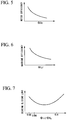
FIG. 6 is a graph showing a relationship between an outer diameter ΦLJ of a rotary shaft and machine efficiency. -
FIG. 7 is a graph showing a relationship between ΦLJ / ΦMo which is a ratio between the outer diameter ΦLJ of the rotary shaft and the outer diameter ΦMo of the stator core, and a sliding loss at a bearing. - Hereinafter, a sealed rotary compressor 1 (hereinafter, referred to as compressor 1) according to an embodiment of the present invention will be described.
- As shown in
FIG. 1 , a compressor 1 includes acylindrical case 2, anelectric motor 3 which is accommodated inside thecase 2, arotary shaft 5 which is driven by theelectric motor 3 inside thecase 2,bearings 17 and 18 (upper bearing 17 and lower bearing 18) which supports therotary shaft 5 inside thecase 2, apiston rotor 15 which is attached to therotary shaft 5 inside thecase 2, and acylinder 16 which is provides inside thecase 2 and accommodates thepiston rotor 15. - The compressor 1 is connected to a refrigerant circuit (not shown). That is, the compressor 1 is a device which is incorporated into the refrigerant circuit including a condenser, an expansion valve, an evaporator, or the like and compresses a refrigerant flowing through a pipe of the refrigerant circuit.
- The
case 2 includes atubular body 7, an upper cover 8 which is welded to an upper end of thebody 7, and a bottom cover 9 which is welded to a lower end of thebody 7. Theelectric motor 3, thepiston rotor 15, and thecylinder 16 are sealed inside thecase 2. Asuction pipe 10 connected to thecylinder 16 is provided in thebody 7. For example, thesuction pipe 10 is a pipe through which a refrigerant gas G is sucked into thecylinder 16 via an accumulator (not shown). A discharge space to which the compressed refrigerant gas G is exhausted from thecylinder 16 is formed inside thecase 2. The refrigerant gas G filling the inside of the discharge space is discharged to the refrigerant circuit through thedischarge pipe 14 penetrating the upper cover 8. - The
electric motor 3 includes arotor core 12, and astator core 11 and astator coil 13 disposed on an outer peripheral side of therotor core 12. - The
stator core 11 is formed of an electromagnetic steel sheet and is formed in a cylindrical shape about an axis O. Thestator core 11 is provided to be fixed to an inner peripheral surface of thecase 2. - The
stator coil 13 is provided so as to be wound around thestator core 11. - Here, an outer diameter of the
stator core 11 is defined as ΦMo. - The
rotor core 12 is formed of an electromagnetic steel sheet and a magnet and is formed in a columnar shape about the axis O. Therotor core 12 can rotate about the axis O by a power supply to thestator core 11. In therotor core 12, a through-hole 12a which is formed in a columnar shape about the axis O and penetrates therotor core 12 in the direction of the axis O is formed. A balance weight 25 (counterweight) is attached to therotor core 12 in order to prevent run-out of therotor core 12 when theelectric motor 3 is driven. Thebalance weight 25 is attached to the lower portion of therotor core 12. Thebalance weight 25 is formed of stainless steel. Thebalance weight 25 is not necessarily formed of stainless steel and may be formed of any nonmagnetic material such as a copper alloy or steel. - The
rotary shaft 5 is formed in a columnar shape about the axis O and extends in the direction of the axis O along a vertical direction. Therotary shaft 5 is inserted into the through-hole 12a of therotor core 12, and thus, is fixed to the inner portion of therotor core 12. Accordingly, a rotational driving force generated by theelectric motor 3 is output from therotor core 12 to therotary shaft 5. - Here, an outer diameter (≅a diameter of the through-
hole 12a) of therotary shaft 5 is defined as ΦLJ. - The
upper bearing 17 and thelower bearing 18 are spaced apart from each other in the direction of the axis O, that is, the vertical direction and are disposed at the lower portion of thecase 2. Theupper bearing 17 and thelower bearing 18 support therotary shaft 5 in a cantilever manner such that a first end portion (the upper portion inFIG. 1 ) of therotary shaft 5 becomes a free end side and can rotate around the axis O with respect to thecase 2. More specifically, therotary shaft 5 protrudes downward from therotor core 12 and only a second end portion (the lower portion inFIG. 1 ) opposite to the first end portion is supported by theupper bearing 17 and thelower bearing 18. - The
piston rotor 15 is attached to the second end portion of therotary shaft 5 to be eccentric to the axis O, and thus, thepiston rotor 15 eccentrically rotates according to rotation of therotary shaft 5. - A
compression chamber 19 in which thepiston rotor 15 is accommodated and sealed is formed inside thecylinder 16 so as to be interposed between theupper bearing 17 and thelower bearing 18. Thesuction pipe 10 is connected to thecylinder 16, and asupply flow path 20 through which the refrigerant gas G is supplied into thecompression chamber 19 is formed. Thepiston rotor 15 rotates by the rotation of therotary shaft 5, a volume of thecompression chamber 19 inside thecylinder 16 gradually decreases, and thus, the refrigerant gas G is compressed. Thecylinder 16 includes an innerperipheral surface 16a which slides to have a minute clearance between the outer peripheral surface of thepiston rotor 15 at one location on the periphery of thecylinder 16 and has a cylindrical surface shape. An axis center of the innerperipheral surface 16a of thecylinder 16 coincides with the axis O. An inner diameter of the innerperipheral surface 16a is the inner diameter ΦDc of thecylinder 16. - Here, the volume of the
compression chamber 19 of thecylinder 16 is a volume obtained by subtracting the volume of thepiston rotor 15 inside thecompression chamber 19 from a volume of a space which has the inner diameter ΦDc of thecylinder 16 as a diameter. The volume of thecompression chamber 19 is a so-called cylinder exclusion volume. Accordingly, the cylinder exclusion volume is correlated with the inner diameter ΦDc of thecylinder 16, and the cylinder exclusion volume decreases as the inner diameter ΦDc of thecylinder 16 decreases. - Here, in the present embodiment, the outer diameter ΦMo of the
stator core 11 and the inner diameter ΦDc of thecylinder 16 satisfy the following Expression (1).
- In the present embodiment, the outer diameter ΦMo of the
stator core 11 and the inner diameter ΦDc of thecylinder 16 may satisfy the following Expression (2).
- In the present embodiment, the outer diameter ΦMo of the
stator core 11 and the inner diameter ΦDc of thecylinder 16 may satisfy the following Expression (3).
- In the present embodiment, the outer diameter ΦLJ of the
rotary shaft 5 and the outer diameter ΦMo of thestator core 11 may satisfy the following Expression (4).
- In the present embodiment, the outer diameter ΦLJ of the
rotary shaft 5 and the outer diameter ΦMo of thestator core 11 may satisfy the following Expression (5).
- In the present embodiment, the outer diameter ΦLJ of the
rotary shaft 5 and the outer diameter ΦMo of thestator core 11 may satisfy the following Expression (6).
- Here, as shown in
FIG. 2 , it is known that an iron loss (eddy current loss) at thestator core 11 can be reduced as the outer diameter ΦMo of thestator core 11 increases. Accordingly, it is possible to improve the efficiency of theelectric motor 3 by increasing the outer diameter ΦMo of thestator core 11. - Moreover, as shown in
FIG. 3 , under conditions of obtaining predetermined compression capacity by the compressor 1, it is known that it is necessary to increase the number of revolution of theelectric motor 3 if the inner diameter ΦDc (the value correlated with the cylinder exclusion volume) of thecylinder 16 decreases. That is, if the inner diameter of the cylinder 16 : Dc1 < Dc2, the number of revolution of the electric motor 3 : rps2 < rps1. - As shown in
FIG. 4 , it is known that a decrease rate of the motor efficiency increases as the number of revolutionof theelectric motor 3 moves toward a region of a low number of revolution. Accordingly, if theelectric motor 3 is operated at a region of a low number of revolution, the motor efficiency decreases. - Therefore, under conditions of obtaining predetermined compression capacity by the compressor 1, if the inner diameter ΦDc of the
cylinder 16 decreases, the number of revolution of theelectric motor 3 increases. As a result, as shown inFIG. 5 , the efficiency of theelectric motor 3 is improved. - By setting the outer diameter ΦMo of the
stator core 11 large and (or) setting the inner diameter ΦDc of the cylinder small so as to set the value of ΦDc / ΦMo to 0.350 or less as described in Expression (1), it is found that sufficient efficiency of theelectric motor 3 can be obtained even when application to an actual machine is considered. - In the compressor 1 of the present embodiment, the outer diameter ΦMo of the
stator core 11 and the inner diameter ΦDc of thecylinder 16 satisfy the above Expression (1): ΦDc / ΦMo ≤ 0.350. In the compressor 1 of the present embodiment, by forming theelectric motor 3 and thecylinder 16 such that the value of ΦDc / ΦMo is 0.350 or less, it is possible to improve efficiency of theelectric motor 3 and achieve high efficiency of the compressor 1 by a simple method based on a simple index like Expression (1) without significantly changing the installation space or the external shape of the compressor 1. - If the outer diameter ΦMo of the
stator core 11 and the inner diameter ΦDc of thecylinder 16 satisfy the above Expression (2): ΦDc / ΦMo ≤ 0.320, it is found that the efficiency of theelectric motor 3 can be further improved and further improvement of the efficiency of the compressor 1 can be achieved. Accordingly, in the compressor 1 of the present embodiment, by forming theelectric motor 3 and thecylinder 16 such that the value of ΦDc / ΦMo is 0.320 or less, it is possible to achieve further improvement of the efficiency of the compressor 1 without significantly changing the installation space or the external shape of the compressor 1. - When specifications of an actual machine are considered, if the outer diameter ΦMo of the
stator core 11 and the inner diameter ΦDc of thecylinder 16 satisfy the above Expression (3): 0.200 ≤ ΦDc / ΦMo s 0.320, it is found that the efficiency of theelectric motor 3 can be further improved and further improvement of the efficiency of the compressor 1 can be achieved. Accordingly, in the compressor 1 of the present embodiment, by forming theelectric motor 3 and thecylinder 16 such that the value of ΦDc / ΦMo is 0.320 or less and 0.200 or more, it is possible to achieve further improvement of the efficiency of the compressor 1 without significantly changing the installation space or the external shape of the compressor 1. - Here, as shown in
FIG. 6 , it is known that a sliding loss between therotary shaft 5 and theupper bearing 17, between therotary shaft 5 and thelower bearing 18, or the like can be reduced if the outer diameter ΦLJ of therotary shaft 5 decreases. - Accordingly, it is possible to improve machine efficiency by setting the outer diameter ΦLJ of the
rotary shaft 5 small. As described above, it is possible to reduce the iron loss (eddy current loss) at thestator core 11 and improve the efficiency of theelectric motor 3 by setting the outer diameter ΦMo of thestator core 11 large. Therefore, by setting the outer diameter ΦLJ of therotary shaft 5 to be smaller than the outer diameter ΦMo of thestator core 11 and setting the value of ΦLJ / ΦMo to 0.140 or less as described in Expression (4), it is found that sufficient efficiency of the compressor 1 can be obtained even when application to an actual machine is considered. - Accordingly, in the compressor 1 of the present embodiment, by forming the
electric motor 3 and therotary shaft 5 such that the outer diameter ΦLJ of therotary shaft 5 and the outer diameter ΦMo of thestator core 11 further satisfy the above Expression (4): ΦLJ / ΦMo ≤ 0.140, it is possible to improve efficiency of theelectric motor 3 and achieve high efficiency of the compressor 1 by a simple method based on a simple index like Expression (4) without significantly changing the shape, the installation space, or the like of the compressor 1. - Moreover, the
rotary shaft 5 which is not formed of an electromagnetic steel sheet is inserted into therotor core 12 formed of an electromagnetic steel sheet. In the present embodiment, by decreasing the outer diameter ΦLJ of therotary shaft 5, it is possible to decrease the diameter of the through-hole 12a of therotor core 12, and thus, it is possible to increase the number of electromagnetic steel sheets in therotor core 12. Accordingly, it is possible to reduce a magnetic resistance of therotor core 12, the efficiency of theelectric motor 3 can be improved, and high efficiency of the compressor 1 can be achieved. - Here, if the outer diameter ΦLJ of the rotary shaft becomes too small, one-sided contact is likely to occur between the
upper bearing 17 and therotary shaft 5 and between thelower bearing 18 and therotary shaft 5. Accordingly, it is found that the sliding loss increases in a region where ΦLJ is smaller than a predetermined value, and as shown inFIG. 7 , in the value of ΦLJ / ΦMo, the minimum value exists, at which the sliding loss between theupper bearing 17 and therotary shaft 5 and between thelower bearing 18 and therotary shaft 5 is smallest. It is found that the minimum value of ΦLJ ΦMo is a value which is 0.0800 or more, 0.0106 or more, and 0.140 or less. - Accordingly, in the present embodiment, when specifications of an actual machine are considered, by forming the
rotary shaft 5 and theelectric motor 3 such that the outer diameter ΦLJ of therotary shaft 5 and the outer diameter ΦMo of thestator core 11 further satisfy the above Expression (5): 0.0800 ≤ ΦLJ / ΦMo ≤ 0.140, it is possible to reduce the sliding loss and achieve further improvement of the efficiency of the compressor 1 without significantly changing the installation space or the external shape of the compressor 1. - In the present embodiment, by forming the
rotary shaft 5 and theelectric motor 3 such that the outer diameter ΦLJ of therotary shaft 5 and the outer diameter ΦMo of thestator core 11 satisfy the above Expression (6): 0.0106 ≤ ΦLJ / ΦMo ≤ 0.140, it is possible to further reduce the sliding loss and achieve further improvement of the efficiency of the compressor 1 without significantly changing the installation space or the like of the compressor 1. - Hereinbefore, the embodiment of the present invention is described with reference the drawings. However, configurations of the embodiment, combinations thereof, or the like are examples of the present invention, and additions, omissions, substitutions, and other modifications of the configurations can be made within a scope which does not depart from the gist of the present invention. Moreover, the invention is not limited to the embodiment, and is only limited by claims.
- For example, in the above descriptions, the sealed rotary compressor 1 is described. However, the above-described configuration may also be applied to a sealed two-stage compressor or the like which further includes a scroll compression mechanism on the upper portion in the
case 2. -
- 1: sealed rotary compressor
- 2: case
- 3: electric motor
- 5: rotary shaft
- 7: body
- 8: upper cover
- 9: bottom cover
- 10: suction pipe
- 11: stator core
- 12: rotor core
- 12a: through-hole
- 13: stator coil
- 14: discharge pipe
- 15: piston rotor
- 16: cylinder
- 16a: inner peripheral surface
- 17: upper bearing
- 18: lower bearing
- 19: compression chamber
- 20: supply flow path
- 25: balance weight
- O: axis
- G: refrigerant gas
Claims (6)
- A sealed rotary compressor (1), comprising:an electric motor (3);a rotary shaft (5) which is capable of being rotated around an axis (O) by the electric motor (3);a piston rotor (15) which is provided on the rotary shaft (5) and rotates to be eccentric with respect to the axis (O) according to rotation of the rotary shaft (5);a cylinder (16) in which a compression chamber (19) in which the piston rotor (15) is accommodated is formed inside the cylinder (16) and a supply flow path (20) through which a refrigerant is supplied to the compression chamber (19) is formed;a case (2) which surrounds the cylinder (16) to form, between the cylinder (16) and the case (2), a discharge space to which the refrigerant compressed by the piston rotor (15) is exhausted and in which the electric motor (3), the rotary shaft (5), the piston rotor (15), and the cylinder (16) are accommodated in a sealed manner; anda bearing which supports the rotary shaft (5) to the case (2),wherein the electric motor (3) includes a rotor core (12) which fixes the rotary shaft (5) to the inner portion of the rotor core (12), a stator core (11) which is fixed to the case (2) on an outer peripheral side of the rotor core (12), and a stator coil (13) which is provided in the stator core (11), andwherein when an outer diameter of the stator core (11) is defined as ΦMo and an inner diameter of the cylinder (16) is defined as ΦDc, the following Expression (1) is satisfied.

- The sealed rotary compressor (1) according to claim 1,
wherein when the outer diameter of the stator core (11) is defined as ΦMo and the inner diameter of the cylinder (16) is defined as ΦDc, the following Expression (2) is further satisfied.
- The sealed rotary compressor (1) according to claim 2,wherein when the outer diameter of the stator core (11) is defined as ΦMo and the inner diameter of the cylinder (16) is defined as ΦDc, the following Expression (3) is further satisfied.

- The sealed rotary compressor (1) according to any one of claims 1 to 3,wherein when an outer diameter of the rotary shaft (5) is defined as ΦLJ, the following Expression (4) is further satisfied.

- The sealed rotary compressor (1) according to claim 4,wherein when the outer diameter of the rotary shaft (5) is defined as ΦLJ, the following Expression (5) is further satisfied.

- The sealed rotary compressor (1) according to claim 5,wherein when the outer diameter of the rotary shaft (5) is defined as ΦLJ, the following Expression (6) is further satisfied.

Applications Claiming Priority (1)
| Application Number | Priority Date | Filing Date | Title |
|---|---|---|---|
| JP2016205252A JP6270080B1 (en) | 2016-10-19 | 2016-10-19 | Hermetic rotary compressor |
Publications (1)
| Publication Number | Publication Date |
|---|---|
| EP3312424A1 true EP3312424A1 (en) | 2018-04-25 |
Family
ID=60117605
Family Applications (1)
| Application Number | Title | Priority Date | Filing Date |
|---|---|---|---|
| EP17196702.9A Withdrawn EP3312424A1 (en) | 2016-10-19 | 2017-10-16 | Sealed rotary compressor |
Country Status (2)
| Country | Link |
|---|---|
| EP (1) | EP3312424A1 (en) |
| JP (1) | JP6270080B1 (en) |
Families Citing this family (3)
| Publication number | Priority date | Publication date | Assignee | Title |
|---|---|---|---|---|
| CN106321617B (en) * | 2016-10-26 | 2023-10-31 | 上海海立电器有限公司 | Crankshaft and rotary compressor |
| EP3936721B1 (en) | 2019-05-10 | 2026-01-28 | Mitsubishi Heavy Industries Thermal Systems, Ltd. | Compressor and tool |
| WO2026000548A1 (en) * | 2024-06-25 | 2026-01-02 | 上海海立电器有限公司 | Rotary compressor |
Citations (6)
| Publication number | Priority date | Publication date | Assignee | Title |
|---|---|---|---|---|
| WO2004102005A1 (en) * | 2003-05-19 | 2004-11-25 | Matsushita Electric Industrial Co., Ltd. | Compressor |
| WO2006112100A1 (en) * | 2005-03-30 | 2006-10-26 | Matsushita Electric Industrial Co., Ltd. | Compressor |
| EP1790857A1 (en) * | 2005-11-28 | 2007-05-30 | Sanyo Electric Co., Ltd. | Rotary piston compressor |
| WO2010117214A2 (en) * | 2009-04-09 | 2010-10-14 | 엘지전자 주식회사 | Rotary-type 2-stage compressor |
| JP2011153526A (en) | 2010-01-26 | 2011-08-11 | Panasonic Corp | Hermetically sealed rotary compressor |
| US8912701B2 (en) * | 2010-12-28 | 2014-12-16 | Mitsubishi Electric Corporation | Induction motor, compressor and refrigerating cycle apparatus |
Family Cites Families (6)
| Publication number | Priority date | Publication date | Assignee | Title |
|---|---|---|---|---|
| JPH03258988A (en) * | 1990-03-06 | 1991-11-19 | Matsushita Refrig Co Ltd | Rotary compressor |
| JP2003184771A (en) * | 2001-12-12 | 2003-07-03 | Sanyo Electric Co Ltd | Rotary compressor |
| JP2007224875A (en) * | 2006-02-27 | 2007-09-06 | Matsushita Electric Ind Co Ltd | Compressor |
| WO2009028633A1 (en) * | 2007-08-28 | 2009-03-05 | Toshiba Carrier Corporation | Multicylinder rotary type compressor, and refrigerating cycle apparatus |
| JP2012039702A (en) * | 2010-08-04 | 2012-02-23 | Honda Motor Co Ltd | Synchronous motor |
| JP5195962B2 (en) * | 2011-05-11 | 2013-05-15 | 三菱電機株式会社 | Rotary compressor |
-
2016
- 2016-10-19 JP JP2016205252A patent/JP6270080B1/en active Active
-
2017
- 2017-10-16 EP EP17196702.9A patent/EP3312424A1/en not_active Withdrawn
Patent Citations (6)
| Publication number | Priority date | Publication date | Assignee | Title |
|---|---|---|---|---|
| WO2004102005A1 (en) * | 2003-05-19 | 2004-11-25 | Matsushita Electric Industrial Co., Ltd. | Compressor |
| WO2006112100A1 (en) * | 2005-03-30 | 2006-10-26 | Matsushita Electric Industrial Co., Ltd. | Compressor |
| EP1790857A1 (en) * | 2005-11-28 | 2007-05-30 | Sanyo Electric Co., Ltd. | Rotary piston compressor |
| WO2010117214A2 (en) * | 2009-04-09 | 2010-10-14 | 엘지전자 주식회사 | Rotary-type 2-stage compressor |
| JP2011153526A (en) | 2010-01-26 | 2011-08-11 | Panasonic Corp | Hermetically sealed rotary compressor |
| US8912701B2 (en) * | 2010-12-28 | 2014-12-16 | Mitsubishi Electric Corporation | Induction motor, compressor and refrigerating cycle apparatus |
Also Published As
| Publication number | Publication date |
|---|---|
| JP6270080B1 (en) | 2018-01-31 |
| JP2018066314A (en) | 2018-04-26 |
Similar Documents
| Publication | Publication Date | Title |
|---|---|---|
| CN102220978B (en) | Hermetic compressor | |
| CN110131126B (en) | Pump system, axial flux motor and compressor | |
| EP2818709B1 (en) | Linear compressor | |
| EP2960507A1 (en) | Linear compressor, shell for linear compressor, and method for manufacturing shell of linear compressor | |
| CN109072917B (en) | Rotary compressor and refrigeration cycle device | |
| EP2905470B1 (en) | Rotary compressor | |
| EP2811164B1 (en) | Scroll compressor | |
| US9388808B2 (en) | Scroll compression device | |
| CN101535645B (en) | Compressor | |
| JP6270080B1 (en) | Hermetic rotary compressor | |
| JP6407432B2 (en) | Compressor and refrigeration cycle apparatus | |
| EP4411136A1 (en) | Compressor unit | |
| CN203747602U (en) | Motor, compressor and refrigeration cycle device | |
| KR101001837B1 (en) | Compressors Motors and Compressors | |
| EP3337014A2 (en) | Rotor of electric motor and compressor | |
| EP3315774A1 (en) | Hermetic electric compressor | |
| EP3364030B1 (en) | Compressor provided with a housing | |
| WO2018131436A1 (en) | Compressor comprising shaft support | |
| JP5135779B2 (en) | Compressor | |
| JP2019074067A (en) | Hermetic electric compressor | |
| EP4477891A1 (en) | Centrifugal compressor and refrigeration device | |
| JP2011074814A (en) | Rotary compressor and manufacturing method for the same | |
| JP6558346B2 (en) | Compressor capable of suppressing refrigeration oil discharge | |
| JPWO2018146764A1 (en) | Rotary compressor | |
| KR101406509B1 (en) | An oil recovery member and a transmission mechanism and a compressor using the oil recovery member |
Legal Events
| Date | Code | Title | Description |
|---|---|---|---|
| PUAI | Public reference made under article 153(3) epc to a published international application that has entered the european phase |
Free format text: ORIGINAL CODE: 0009012 |
|
| STAA | Information on the status of an ep patent application or granted ep patent |
Free format text: STATUS: THE APPLICATION HAS BEEN PUBLISHED |
|
| AK | Designated contracting states |
Kind code of ref document: A1 Designated state(s): AL AT BE BG CH CY CZ DE DK EE ES FI FR GB GR HR HU IE IS IT LI LT LU LV MC MK MT NL NO PL PT RO RS SE SI SK SM TR |
|
| AX | Request for extension of the european patent |
Extension state: BA ME |
|
| STAA | Information on the status of an ep patent application or granted ep patent |
Free format text: STATUS: REQUEST FOR EXAMINATION WAS MADE |
|
| 17P | Request for examination filed |
Effective date: 20181019 |
|
| RBV | Designated contracting states (corrected) |
Designated state(s): AL AT BE BG CH CY CZ DE DK EE ES FI FR GB GR HR HU IE IS IT LI LT LU LV MC MK MT NL NO PL PT RO RS SE SI SK SM TR |
|
| GRAP | Despatch of communication of intention to grant a patent |
Free format text: ORIGINAL CODE: EPIDOSNIGR1 |
|
| STAA | Information on the status of an ep patent application or granted ep patent |
Free format text: STATUS: GRANT OF PATENT IS INTENDED |
|
| INTG | Intention to grant announced |
Effective date: 20200529 |
|
| STAA | Information on the status of an ep patent application or granted ep patent |
Free format text: STATUS: THE APPLICATION IS DEEMED TO BE WITHDRAWN |
|
| 18D | Application deemed to be withdrawn |
Effective date: 20201009 |