EP3312381A1 - Well testing with jet pump - Google Patents
Well testing with jet pump Download PDFInfo
- Publication number
- EP3312381A1 EP3312381A1 EP17196335.8A EP17196335A EP3312381A1 EP 3312381 A1 EP3312381 A1 EP 3312381A1 EP 17196335 A EP17196335 A EP 17196335A EP 3312381 A1 EP3312381 A1 EP 3312381A1
- Authority
- EP
- European Patent Office
- Prior art keywords
- well
- fluid
- jet pump
- parameter sensor
- throat
- Prior art date
- Legal status (The legal status is an assumption and is not a legal conclusion. Google has not performed a legal analysis and makes no representation as to the accuracy of the status listed.)
- Withdrawn
Links
Images

Classifications
-
- E—FIXED CONSTRUCTIONS
- E21—EARTH OR ROCK DRILLING; MINING
- E21B—EARTH OR ROCK DRILLING; OBTAINING OIL, GAS, WATER, SOLUBLE OR MELTABLE MATERIALS OR A SLURRY OF MINERALS FROM WELLS
- E21B47/00—Survey of boreholes or wells
- E21B47/06—Measuring temperature or pressure
-
- E—FIXED CONSTRUCTIONS
- E21—EARTH OR ROCK DRILLING; MINING
- E21B—EARTH OR ROCK DRILLING; OBTAINING OIL, GAS, WATER, SOLUBLE OR MELTABLE MATERIALS OR A SLURRY OF MINERALS FROM WELLS
- E21B34/00—Valve arrangements for boreholes or wells
- E21B34/06—Valve arrangements for boreholes or wells in wells
- E21B34/08—Valve arrangements for boreholes or wells in wells responsive to flow or pressure of the fluid obtained
-
- E—FIXED CONSTRUCTIONS
- E21—EARTH OR ROCK DRILLING; MINING
- E21B—EARTH OR ROCK DRILLING; OBTAINING OIL, GAS, WATER, SOLUBLE OR MELTABLE MATERIALS OR A SLURRY OF MINERALS FROM WELLS
- E21B41/00—Equipment or details not covered by groups E21B15/00 - E21B40/00
- E21B41/0078—Nozzles used in boreholes
-
- E—FIXED CONSTRUCTIONS
- E21—EARTH OR ROCK DRILLING; MINING
- E21B—EARTH OR ROCK DRILLING; OBTAINING OIL, GAS, WATER, SOLUBLE OR MELTABLE MATERIALS OR A SLURRY OF MINERALS FROM WELLS
- E21B43/00—Methods or apparatus for obtaining oil, gas, water, soluble or meltable materials or a slurry of minerals from wells
- E21B43/12—Methods or apparatus for controlling the flow of the obtained fluid to or in wells
-
- E—FIXED CONSTRUCTIONS
- E21—EARTH OR ROCK DRILLING; MINING
- E21B—EARTH OR ROCK DRILLING; OBTAINING OIL, GAS, WATER, SOLUBLE OR MELTABLE MATERIALS OR A SLURRY OF MINERALS FROM WELLS
- E21B43/00—Methods or apparatus for obtaining oil, gas, water, soluble or meltable materials or a slurry of minerals from wells
- E21B43/12—Methods or apparatus for controlling the flow of the obtained fluid to or in wells
- E21B43/121—Lifting well fluids
- E21B43/124—Adaptation of jet-pump systems
-
- E—FIXED CONSTRUCTIONS
- E21—EARTH OR ROCK DRILLING; MINING
- E21B—EARTH OR ROCK DRILLING; OBTAINING OIL, GAS, WATER, SOLUBLE OR MELTABLE MATERIALS OR A SLURRY OF MINERALS FROM WELLS
- E21B47/00—Survey of boreholes or wells
- E21B47/01—Devices for supporting measuring instruments on drill bits, pipes, rods or wirelines; Protecting measuring instruments in boreholes against heat, shock, pressure or the like
- E21B47/017—Protecting measuring instruments
-
- E—FIXED CONSTRUCTIONS
- E21—EARTH OR ROCK DRILLING; MINING
- E21B—EARTH OR ROCK DRILLING; OBTAINING OIL, GAS, WATER, SOLUBLE OR MELTABLE MATERIALS OR A SLURRY OF MINERALS FROM WELLS
- E21B49/00—Testing the nature of borehole walls; Formation testing; Methods or apparatus for obtaining samples of soil or well fluids, specially adapted to earth drilling or wells
- E21B49/08—Obtaining fluid samples or testing fluids, in boreholes or wells
- E21B49/087—Well testing, e.g. testing for reservoir productivity or formation parameters
- E21B49/0875—Well testing, e.g. testing for reservoir productivity or formation parameters determining specific fluid parameters
-
- F—MECHANICAL ENGINEERING; LIGHTING; HEATING; WEAPONS; BLASTING
- F04—POSITIVE - DISPLACEMENT MACHINES FOR LIQUIDS; PUMPS FOR LIQUIDS OR ELASTIC FLUIDS
- F04F—PUMPING OF FLUID BY DIRECT CONTACT OF ANOTHER FLUID OR BY USING INERTIA OF FLUID TO BE PUMPED; SIPHONS
- F04F5/00—Jet pumps, i.e. devices in which flow is induced by pressure drop caused by velocity of another fluid flow
- F04F5/44—Component parts, details, or accessories not provided for in, or of interest apart from, groups F04F5/02 - F04F5/42
- F04F5/46—Arrangements of nozzles
- F04F5/464—Arrangements of nozzles with inversion of the direction of flow
Definitions
- This disclosure relates generally to equipment utilized and operations performed in conjunction with a subterranean well and, in an example described below, more particularly provides apparatus, systems and methods for well testing with a jet pump.
- a jet pump uses the Bernoulli principle to draw production fluid toward a relatively low pressure region created when a power fluid pumped from surface flows through a nozzle and into a throat of the jet pump.
- the power fluid and the production fluid commingle in the throat and then flow through a diffuser (in which pressure in the commingled fluids is increased) before being produced to surface.
- a bottomhole well pressure test can be performed to measure static well pressure for production planning, monitoring or diagnostic purposes.
- a well is shut in (thereby preventing production flow to surface), and a pressure sensor or gauge is used to measure pressure in the production fluid at a desired downhole location (such as, at a production zone).
- a first aspect of the present disclosure provides a fluid production apparatus for use with a subterranean well, the fluid production apparatus comprising: a jet pump including a nozzle aligned with a throat, a flow passage configured for conducting production fluid to the throat, and at least one check valve that prevents flow from the throat to the flow passage and permits flow from the flow passage to the throat.
- the fluid production apparatus may further comprise a well parameter sensor in communication with the flow passage.
- the check valve may prevent flow from the throat to the well parameter sensor.
- the well parameter sensor may be included with a well parameter recorder.
- the well parameter sensor may be disposed longitudinally between the jet pump and a retrieval connector configured for retrieving the fluid production apparatus from the well.
- the jet pump may be disposed longitudinally between the well parameter sensor and a standing valve.
- the flow passage may extend longitudinally beyond both opposite ends of the jet pump.
- a fluid production system for use with a subterranean well, the fluid production system comprising: a jet pump sealingly received in a bottomhole assembly connected in a tubular string, the jet pump comprising a throat that receives a power fluid from a nozzle and receives a production fluid from a flow passage, the jet pump further comprising at least one check valve that permits flow of the production fluid from the flow passage to the throat and prevents flow of the power fluid to the flow passage.
- the fluid production system may further comprise a well parameter sensor connected to the jet pump.
- the check valve may prevent flow of the power fluid to the well parameter sensor.
- the fluid production system may further comprise a standing valve, and the jet pump may be connected longitudinally between the standing valve and the well parameter sensor.
- the jet pump and the well parameter sensor may be retrievable together from the bottomhole assembly.
- the well parameter sensor may be connected between the jet pump and a retrieval connector.
- FIG. 1 Representatively illustrated in FIG. 1 is a fluid production system 10 for use with a well, and an associated method, which can embody principles of this disclosure.
- system 10 and method are merely one example of an application of the principles of this disclosure in practice, and a wide variety of other examples are possible. Therefore, the scope of this disclosure is not limited at all to the details of the system 10 and method described herein and/or depicted in the drawings.
- the well includes a generally vertical wellbore 12 lined with casing 14 and cement 16. Perforations 18 formed through the casing 14 and cement 16 provide for flow of production fluid 20 to an interior of the wellbore 12 from a production zone 22 penetrated by the wellbore 12.
- sections of the wellbore 12 may be inclined or deviated from vertical, the fluid 20 could be produced at an uncased or open hole section of the wellbore 12, etc.
- the scope of this disclosure is not limited to any details of the well as depicted in the drawings or described herein.
- a tubular string 24 (such as, a production tubing string, a coiled tubing string, etc.) is positioned in the casing 14.
- An annulus 26 is formed radially between the casing 14 and the tubular string 24.
- the tubular string 24 includes a generally tubular bottomhole assembly 28.
- the assembly 28 is "bottomhole” in that it is connected at or near a distal end of the tubular string 24 in the wellbore 12.
- the assembly 28 is not necessarily positioned at a bottom of the wellbore 12.
- the fluid production apparatus 30 may be conveyed into, and retrieved from, the bottomhole assembly 28 by wireline, slickline, coiled tubing, tractor, robot, flow or any other type of conveyance 32 or technique for transporting the apparatus 30 in the tubular string 24.
- a power fluid 34 is pumped from surface to the apparatus 30 via the conveyance 32.
- the power fluid 34 may be pumped to the apparatus 30 via the tubular string 24, or via an annulus 36 formed radially between the tubular string 24 and the conveyance 32.
- the power fluid 34 flows outward into the annulus 36 from ports 38 formed in an upper retrieval connector 40 of the apparatus 30.
- the power fluid 34 flows through the annulus 36 and enters ports 42 of a jet pump 44.
- the power fluid 34 flows through a nozzle 46. This increases a velocity of the power fluid 34 and thereby reduces a pressure in the power fluid.
- the nozzle 46 is aligned with a throat 48 of the jet pump 44, so that the power fluid 34 exiting the nozzle 46 at increased velocity and reduced pressure enters the throat 48. There is, however, a gap between the nozzle 46 and the throat 48, into which the production fluid 20 may flow.
- the production fluid 20 enters the jet pump 44 via a standing valve 50.
- the standing valve 50 in this example, is connected below the jet pump 44 in the apparatus 30.
- the standing valve 50 sealingly engages an internal shoulder 51 formed in the bottomhole assembly 28.
- the standing valve 50 is depicted in FIG. 1 as comprising a check valve 52 that permits flow of the production fluid 20 to the jet pump 44 from the wellbore 12 at the production zone 22.
- the check valve 52 prevents reverse flow of the production fluid 20 from the jet pump 44.
- the scope of this disclosure is not limited to use of any particular type or configuration of the standing valve 50.
- the production fluid 20 flows from the standing valve 50 via a flow passage 54 extending longitudinally through the jet pump 44.
- the flow passage 54 extends to a chamber 56 in the apparatus 30 between the jet pump 44 and the upper retrieval connector 40.
- the recorder 58 can be a relatively fragile instrument, and so shock dampeners 60 support the recorder 58 at opposite ends of the chamber 56.
- the recorder 58 includes a well parameter sensor 62.
- the sensor 62 can be in communication with the production fluid 20 in the chamber 56, so the sensor 62 can measure a well parameter (such as, pressure, temperature, resistance, capacitance, density, etc.) of the production fluid 20.
- the recorder 58 can record such measurements over time. More than one sensor 62 may be used to measure more than one well parameter.
- the senor 62 may comprise a pressure sensor for measuring pressure in the production fluid 20 in the chamber 56. Such pressure measurements may be performed and recorded before, during and after the well is shut in (i.e., production flow from the production zone 22 ceases).
- the flow passage 54 is also in one-way communication with the gap between the nozzle 46 and the throat 48 via one or more check valves 64.
- the check valves 64 permit flow of the production fluid 20 from the flow passage 54 to a chamber 66 surrounding the gap between the nozzle 46 and the throat 48, but the check valves 64 prevent flow from the chamber 66 to the flow passage 54.
- the production fluid 20 flows through the check valves 64 and into the chamber 66.
- the production fluid 20 in the chamber 66 is drawn into the relatively low pressure region of the power fluid 34 exiting the nozzle 46 (in the gap between the nozzle 46 and the throat 48), and the commingled production and power fluids 20, 34 flow together into the throat 48.
- the fluids 20, 34 flow through a diffuser 68, in which a velocity of the fluid 20, 34 is decreased and a pressure in the fluids 20, 34 is increased.
- the fluids 20, 34 then exit the jet pump 44 via ports 70.
- the fluids 20, 34 flow into the annulus 36 via the ports 70, and then flow into the annulus 26 via ports 72 in the bottomhole assembly 28.
- the fluids 20, 34 flow to surface via the annulus 26.
- the power fluid 34 is injected into the well and, due to the interaction of the jet pump 44 and the remainder of the apparatus 30 and the bottom hole assembly 28, the power fluid 34 and production fluid 20 are flowed to surface.
- check valves 64 prevent the power fluid 34 from flowing into the flow passage 54.
- the flow passage 54 is desirably isolated from all downhole pressure sources, other than the production fluid 20.
- the check valves 64 may be useful in other types of tests, as well.
- FIG. 2 an example of the fluid production system 10 is representatively illustrated apart from the well of FIG. 1 .
- the FIG. 2 fluid production system 10 example may be used in wells other than the well of FIG. 1 .
- FIG. 2 further details of the system 10 are visible. Note that the system 10 is depicted in FIG. 2 in a fluid production configuration, with the power fluid 34 being pumped from surface into the annulus 36 via the connector 40, and the commingled production and power fluids 20, 34 flowing to surface via the annulus 26.
- the power fluid 34 flows from the annulus 36 through the nozzle 46 to the throat 48.
- the power fluid 34 becomes commingled with the production fluid 20 in the gap between the nozzle 46 and the throat 48.
- the production fluid 20 enters the apparatus 30 via the standing valve 50, which is schematically depicted in FIG. 2 .
- the standing valve 50 may include the check valve 52 of FIG. 1 , or another type of valve.
- the production fluid 20 flows into the flow passage 54 from the standing valve 50. From the flow passage 54, the production fluid 20 is in communication with the chamber 56, and in one-way communication with the chamber 66. The one-way communication is provided by the check valves 64 connected between the flow passage 54 and the chamber 66.
- FIG. 3 an enlarged scale cross-sectional view of a section of the jet pump 44 is representatively illustrated.
- the manner in which the flow passage 54 is in communication with both of the chambers 56, 66, but the chamber 56 is isolated from the chamber 66, can be more clearly seen.
- the production fluid 20 can flow from the flow passage 54 to either of the chambers 56, 66.
- the check valves 64 prevent the production and power fluids 20, 34 from flowing from the chamber 66 to the flow passage 54 or chamber 56.
- the fluid production system 10 is representatively illustrated in a bottomhole well pressure test configuration.
- Production flow from the production zone 22 is ceased, so that pressure in the wellbore 12 at the zone 22 will build up to the same as (or substantially the same as) pressure in the zone 22.
- characteristics of pressure in the wellbore 12 such as, maximum buildup pressure, rate/profile of pressure buildup, etc.
- the flow passage 54 is in communication with the wellbore 12 at the zone 22 via the standing valve 50.
- the flow passage 54 is also in communication with the chamber 56 containing the recorder 58.
- the sensor 62 can measure a well parameter (such as, pressure, temperature, etc.) in the production fluid 20.
- the power fluid 34 is not flowed through the apparatus 30. Nonetheless, the check valves 64 prevent pressure in the chamber 66 from being communicated to the flow passage 54 and chamber 56, so that the pressure measurements are unaffected by pressures in the chamber 66, annulus 26 and annulus 36.
- the apparatus 30, including the jet pump 44, the standing valve 50 and the recorder 58 can be conveniently retrieved from the tubular string 24 together.
- a single trip into the well may be used to retrieve the apparatus 30 in this example, thereby saving wellsite time and expense.
- the conveyance 32 is depicted schematically. If the conveyance 32 comprises a wireline, slickline or coiled tubing, then the conveyance 32 can be connected to the retrieval connector 40 and withdrawn from the well to retrieve the apparatus 30 with the conveyance 32.
- the apparatus 30 could be conveyed in the tubular string 24 by flow through the tubular string 24.
- upward flow e.g., in a reverse circulating direction
- upward flow through the tubular string 24 may be used to retrieve the apparatus 30 from the tubular string 24.
- a tractor or robot may be used as the conveyance 32 to autonomously, or semi-autonomously, install and/or retrieve the apparatus 30.
- the robot or tractor may remain in the well between installation and retrieval of the apparatus 30, or the robot or tractor may be removed from the well until retrieval of the apparatus 30 is desired.
- the conveyance 32 comprises a coiled tubing or other type of tubing
- the power fluid 34 may be flowed through the tubing to the apparatus 30 during production.
- the conveyance 32 could include packers or other sealing devices for sealing off the annulus 36 between the apparatus 30 and the bottomhole assembly 28.
- a packer nose with a fishing neck may be provided above, or as a part of, the retrieval connector 40.
- the power fluid 34 in these examples could be pumped through the tubular string 24 to the apparatus 30 sealingly received in the bottomhole assembly 28.
- the fluid production system 10 allows the jet pump 44 to be used for producing fluid 20 to surface, while still allowing the jet pump 44 and a recorder 58 to be retrieved together from a well after a bottomhole well pressure test.
- the fluid production apparatus 30 can include a jet pump 44 with a nozzle 46 aligned with a throat 48, a flow passage 54 configured for conducting production fluid 20 to the throat 48, and at least one check valve 64 that prevents flow from the throat 48 to the flow passage 54 and permits flow from the flow passage 54 to the throat 48.
- the flow passage 54 may extend longitudinally beyond both of opposite ends of the jet pump 44.
- the fluid production apparatus 30 can also include a well parameter sensor 62 in communication with the flow passage 54.
- the check valve 64 may prevent flow from the throat 48 to the well parameter sensor 62.
- the well parameter sensor 62 may be included with a well parameter recorder 58.
- the well parameter sensor 62 may be disposed longitudinally between the jet pump 44 and a retrieval connector 40 configured for retrieving the fluid production apparatus 30 from the well.
- the jet pump 44 may be disposed longitudinally between the well parameter sensor 62 and a standing valve 50.
- a production method for use with a subterranean well is also provided to the art by the above disclosure.
- the method can comprise: performing a bottomhole well pressure test while measuring well pressure with a well parameter sensor 62 connected to a jet pump 44 in the well; and after the bottomhole well pressure test, retrieving the well parameter sensor 62 and the jet pump 44 together from the well.
- the well parameter sensor 62 may be included with a well parameter recorder 58, and the measuring step may include recording measurements of the well pressure.
- the method may include connecting the jet pump 44 between the well parameter sensor 62 and a standing valve 50.
- the method may include connecting the well parameter sensor 62 between the jet pump 44 and a retrieval connector 40 configured for retrieving the jet pump 44 and the well parameter sensor 62 from the well.
- the well parameter sensor 62 may be in communication with a flow passage 54 that receives production fluid 20 from a production zone 22 of the well.
- the method may include at least one check valve 64 permitting flow from the flow passage 54 to a throat 48 of the jet pump 44 and preventing flow from the throat 48 to the flow passage 54.
- the method may include the check valve 64 preventing flow from the throat 48 to the well parameter sensor 62.
- the fluid production system 10 can include a jet pump 44 sealingly received in a bottomhole assembly 28 connected in a tubular string 24, the jet pump 44 comprising a throat 48 that receives a power fluid 34 from a nozzle 46 and receives a production fluid 20 from a flow passage 54, the jet pump 44 further comprising at least one check valve 64 that permits flow of the production fluid 20 from the flow passage 54 to the throat 48 and prevents flow of the power fluid 34 to the flow passage 54.
- the fluid production system 10 may also include a well parameter sensor 62 connected to the jet pump 44.
- the check valve 64 may prevent flow of the power fluid 34 to the well parameter sensor 62.
- the fluid production system 10 may include a standing valve 50, with the jet pump 44 being connected longitudinally between the standing valve 50 and the well parameter sensor 62.
- the jet pump 44 and the well parameter sensor 62 may be retrievable together from the bottomhole assembly 28.
- the well parameter sensor 62 may be connected between the jet pump 44 and a retrieval connector 40.
Landscapes
- Engineering & Computer Science (AREA)
- Geology (AREA)
- Mining & Mineral Resources (AREA)
- Life Sciences & Earth Sciences (AREA)
- Physics & Mathematics (AREA)
- Fluid Mechanics (AREA)
- General Life Sciences & Earth Sciences (AREA)
- Environmental & Geological Engineering (AREA)
- Geochemistry & Mineralogy (AREA)
- Geophysics (AREA)
- General Engineering & Computer Science (AREA)
- Mechanical Engineering (AREA)
- Jet Pumps And Other Pumps (AREA)
- Measuring Fluid Pressure (AREA)
Abstract
Description
- This disclosure relates generally to equipment utilized and operations performed in conjunction with a subterranean well and, in an example described below, more particularly provides apparatus, systems and methods for well testing with a jet pump.
- A jet pump uses the Bernoulli principle to draw production fluid toward a relatively low pressure region created when a power fluid pumped from surface flows through a nozzle and into a throat of the jet pump. The power fluid and the production fluid commingle in the throat and then flow through a diffuser (in which pressure in the commingled fluids is increased) before being produced to surface.
- A bottomhole well pressure test can be performed to measure static well pressure for production planning, monitoring or diagnostic purposes. Typically, a well is shut in (thereby preventing production flow to surface), and a pressure sensor or gauge is used to measure pressure in the production fluid at a desired downhole location (such as, at a production zone).
- It will, therefore, be readily appreciated that it would be desirable to perform a bottomhole well pressure test in circumstances where a jet pump is used for producing fluid from the well. It would also save valuable wellsite time and expense if such a jet pump could be retrieved along with a pressure gauge or recorder used to measure pressure during the test.
- A first aspect of the present disclosure provides a fluid production apparatus for use with a subterranean well, the fluid production apparatus comprising: a jet pump including a nozzle aligned with a throat, a flow passage configured for conducting production fluid to the throat, and at least one check valve that prevents flow from the throat to the flow passage and permits flow from the flow passage to the throat.
- The fluid production apparatus may further comprise a well parameter sensor in communication with the flow passage.
- The check valve may prevent flow from the throat to the well parameter sensor.
- The well parameter sensor may be included with a well parameter recorder.
- The well parameter sensor may be disposed longitudinally between the jet pump and a retrieval connector configured for retrieving the fluid production apparatus from the well.
- The jet pump may be disposed longitudinally between the well parameter sensor and a standing valve.
- The flow passage may extend longitudinally beyond both opposite ends of the jet pump.
- Another aspect of the present disclosure provides a fluid production system for use with a subterranean well, the fluid production system comprising: a jet pump sealingly received in a bottomhole assembly connected in a tubular string, the jet pump comprising a throat that receives a power fluid from a nozzle and receives a production fluid from a flow passage, the jet pump further comprising at least one check valve that permits flow of the production fluid from the flow passage to the throat and prevents flow of the power fluid to the flow passage.
- The fluid production system may further comprise a well parameter sensor connected to the jet pump.
- In a fluid production system of this aspect, the check valve may prevent flow of the power fluid to the well parameter sensor.
- The fluid production system may further comprise a standing valve, and the jet pump may be connected longitudinally between the standing valve and the well parameter sensor.
- In a fluid production system of this aspect the jet pump and the well parameter sensor may be retrievable together from the bottomhole assembly.
- In a fluid production system of this aspect the well parameter sensor may be connected between the jet pump and a retrieval connector.
-
-
FIG. 1 is a representative partially cross-sectional view of an example of a fluid production system and associated method which can embody principles of this disclosure. -
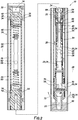
FIG. 2 is a representative cross-sectional view of the fluid production system in a fluid production configuration. -
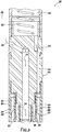
FIG. 3 is a representative cross-sectional view of a section of a jet pump of the fluid production system. -
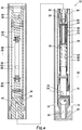
FIG. 4 is a representative cross-sectional view of the fluid production system in a bottomhole well pressure test configuration. - Representatively illustrated in
FIG. 1 is afluid production system 10 for use with a well, and an associated method, which can embody principles of this disclosure. However, it should be clearly understood that thesystem 10 and method are merely one example of an application of the principles of this disclosure in practice, and a wide variety of other examples are possible. Therefore, the scope of this disclosure is not limited at all to the details of thesystem 10 and method described herein and/or depicted in the drawings. - In the
FIG. 1 example, the well includes a generallyvertical wellbore 12 lined withcasing 14 andcement 16.Perforations 18 formed through thecasing 14 andcement 16 provide for flow ofproduction fluid 20 to an interior of thewellbore 12 from aproduction zone 22 penetrated by thewellbore 12. - However, in other examples, sections of the
wellbore 12 may be inclined or deviated from vertical, thefluid 20 could be produced at an uncased or open hole section of thewellbore 12, etc. Thus, the scope of this disclosure is not limited to any details of the well as depicted in the drawings or described herein. - A tubular string 24 (such as, a production tubing string, a coiled tubing string, etc.) is positioned in the
casing 14. Anannulus 26 is formed radially between thecasing 14 and thetubular string 24. - The
tubular string 24 includes a generallytubular bottomhole assembly 28. Theassembly 28 is "bottomhole" in that it is connected at or near a distal end of thetubular string 24 in thewellbore 12. Theassembly 28 is not necessarily positioned at a bottom of thewellbore 12. - Sealingly received in the
bottomhole assembly 28 is afluid production apparatus 30. Thefluid production apparatus 30 may be conveyed into, and retrieved from, thebottomhole assembly 28 by wireline, slickline, coiled tubing, tractor, robot, flow or any other type ofconveyance 32 or technique for transporting theapparatus 30 in thetubular string 24. - As depicted in
FIG. 1 , apower fluid 34 is pumped from surface to theapparatus 30 via theconveyance 32. In other examples, thepower fluid 34 may be pumped to theapparatus 30 via thetubular string 24, or via anannulus 36 formed radially between thetubular string 24 and theconveyance 32. - In the
FIG. 1 example, thepower fluid 34 flows outward into theannulus 36 fromports 38 formed in anupper retrieval connector 40 of theapparatus 30. Thepower fluid 34 flows through theannulus 36 and entersports 42 of ajet pump 44. - In the
jet pump 44, thepower fluid 34 flows through anozzle 46. This increases a velocity of thepower fluid 34 and thereby reduces a pressure in the power fluid. - The
nozzle 46 is aligned with athroat 48 of thejet pump 44, so that thepower fluid 34 exiting thenozzle 46 at increased velocity and reduced pressure enters thethroat 48. There is, however, a gap between thenozzle 46 and thethroat 48, into which theproduction fluid 20 may flow. - The
production fluid 20 enters thejet pump 44 via a standingvalve 50. The standingvalve 50, in this example, is connected below thejet pump 44 in theapparatus 30. The standingvalve 50 sealingly engages aninternal shoulder 51 formed in thebottomhole assembly 28. - The standing
valve 50 is depicted inFIG. 1 as comprising acheck valve 52 that permits flow of theproduction fluid 20 to thejet pump 44 from thewellbore 12 at theproduction zone 22. Thecheck valve 52 prevents reverse flow of theproduction fluid 20 from thejet pump 44. However, the scope of this disclosure is not limited to use of any particular type or configuration of the standingvalve 50. - The
production fluid 20 flows from the standingvalve 50 via aflow passage 54 extending longitudinally through thejet pump 44. In theFIG. 1 example, theflow passage 54 extends to achamber 56 in theapparatus 30 between thejet pump 44 and theupper retrieval connector 40. - Positioned in the
chamber 56 is awell parameter recorder 58. Therecorder 58 can be a relatively fragile instrument, and soshock dampeners 60 support therecorder 58 at opposite ends of thechamber 56. - The
recorder 58 includes awell parameter sensor 62. Thesensor 62 can be in communication with theproduction fluid 20 in thechamber 56, so thesensor 62 can measure a well parameter (such as, pressure, temperature, resistance, capacitance, density, etc.) of theproduction fluid 20. - The
recorder 58 can record such measurements over time. More than onesensor 62 may be used to measure more than one well parameter. - In a bottomhole well pressure test, the
sensor 62 may comprise a pressure sensor for measuring pressure in theproduction fluid 20 in thechamber 56. Such pressure measurements may be performed and recorded before, during and after the well is shut in (i.e., production flow from theproduction zone 22 ceases). - The
flow passage 54 is also in one-way communication with the gap between thenozzle 46 and thethroat 48 via one ormore check valves 64. Thecheck valves 64 permit flow of theproduction fluid 20 from theflow passage 54 to achamber 66 surrounding the gap between thenozzle 46 and thethroat 48, but thecheck valves 64 prevent flow from thechamber 66 to theflow passage 54. - The
production fluid 20 flows through thecheck valves 64 and into thechamber 66. Theproduction fluid 20 in thechamber 66 is drawn into the relatively low pressure region of thepower fluid 34 exiting the nozzle 46 (in the gap between thenozzle 46 and the throat 48), and the commingled production andpower fluids throat 48. - From the
throat 48, thefluids diffuser 68, in which a velocity of the fluid 20, 34 is decreased and a pressure in thefluids fluids jet pump 44 viaports 70. - The
fluids annulus 36 via theports 70, and then flow into theannulus 26 viaports 72 in thebottomhole assembly 28. Thefluids annulus 26. Thus, thepower fluid 34 is injected into the well and, due to the interaction of thejet pump 44 and the remainder of theapparatus 30 and thebottom hole assembly 28, thepower fluid 34 andproduction fluid 20 are flowed to surface. - One benefit of the
check valves 64 is that they prevent thepower fluid 34 from flowing into theflow passage 54. During a bottomhole well pressure test, theflow passage 54 is desirably isolated from all downhole pressure sources, other than theproduction fluid 20. Thecheck valves 64 may be useful in other types of tests, as well. - Referring additionally now to
FIG. 2 , an example of thefluid production system 10 is representatively illustrated apart from the well ofFIG. 1 . TheFIG. 2 fluid production system 10 example may be used in wells other than the well ofFIG. 1 . - In
FIG. 2 , further details of thesystem 10 are visible. Note that thesystem 10 is depicted inFIG. 2 in a fluid production configuration, with thepower fluid 34 being pumped from surface into theannulus 36 via theconnector 40, and the commingled production andpower fluids annulus 26. - The
power fluid 34 flows from theannulus 36 through thenozzle 46 to thethroat 48. Thepower fluid 34 becomes commingled with theproduction fluid 20 in the gap between thenozzle 46 and thethroat 48. - The
production fluid 20 enters theapparatus 30 via the standingvalve 50, which is schematically depicted inFIG. 2 . The standingvalve 50 may include thecheck valve 52 ofFIG. 1 , or another type of valve. - The
production fluid 20 flows into theflow passage 54 from the standingvalve 50. From theflow passage 54, theproduction fluid 20 is in communication with thechamber 56, and in one-way communication with thechamber 66. The one-way communication is provided by thecheck valves 64 connected between theflow passage 54 and thechamber 66. - Referring additionally now to
FIG. 3 , an enlarged scale cross-sectional view of a section of thejet pump 44 is representatively illustrated. In this view, the manner in which theflow passage 54 is in communication with both of thechambers chamber 56 is isolated from thechamber 66, can be more clearly seen. - The
production fluid 20 can flow from theflow passage 54 to either of thechambers check valves 64 prevent the production andpower fluids chamber 66 to theflow passage 54 orchamber 56. - Referring additionally now to
FIG. 4 , thefluid production system 10 is representatively illustrated in a bottomhole well pressure test configuration. Production flow from the production zone 22 (seeFIG. 1 ) is ceased, so that pressure in thewellbore 12 at thezone 22 will build up to the same as (or substantially the same as) pressure in thezone 22. Thus, by measuring characteristics of pressure in the wellbore 12 (such as, maximum buildup pressure, rate/profile of pressure buildup, etc.), characteristics of thezone 22 may be derived. - Note that the
flow passage 54 is in communication with thewellbore 12 at thezone 22 via the standingvalve 50. Theflow passage 54 is also in communication with thechamber 56 containing therecorder 58. Thus, thesensor 62 can measure a well parameter (such as, pressure, temperature, etc.) in theproduction fluid 20. - During the bottomhole well pressure test, the
power fluid 34 is not flowed through theapparatus 30. Nonetheless, thecheck valves 64 prevent pressure in thechamber 66 from being communicated to theflow passage 54 andchamber 56, so that the pressure measurements are unaffected by pressures in thechamber 66,annulus 26 andannulus 36. - After the bottomhole well pressure test, the
apparatus 30, including thejet pump 44, the standingvalve 50 and therecorder 58 can be conveniently retrieved from thetubular string 24 together. Thus, at most, a single trip into the well may be used to retrieve theapparatus 30 in this example, thereby saving wellsite time and expense. - In
FIGS. 2 &4 , theconveyance 32 is depicted schematically. If theconveyance 32 comprises a wireline, slickline or coiled tubing, then theconveyance 32 can be connected to theretrieval connector 40 and withdrawn from the well to retrieve theapparatus 30 with theconveyance 32. - In other examples, the
apparatus 30 could be conveyed in thetubular string 24 by flow through thetubular string 24. In these examples, upward flow (e.g., in a reverse circulating direction) through thetubular string 24 may be used to retrieve theapparatus 30 from thetubular string 24. - In still further examples, a tractor or robot may be used as the
conveyance 32 to autonomously, or semi-autonomously, install and/or retrieve theapparatus 30. The robot or tractor may remain in the well between installation and retrieval of theapparatus 30, or the robot or tractor may be removed from the well until retrieval of theapparatus 30 is desired. - If the
conveyance 32 comprises a coiled tubing or other type of tubing, thepower fluid 34 may be flowed through the tubing to theapparatus 30 during production. Theconveyance 32 could include packers or other sealing devices for sealing off theannulus 36 between theapparatus 30 and thebottomhole assembly 28. - If the
conveyance 32 comprises a wireline or slickline, a packer nose with a fishing neck may be provided above, or as a part of, theretrieval connector 40. Thepower fluid 34 in these examples could be pumped through thetubular string 24 to theapparatus 30 sealingly received in thebottomhole assembly 28. - It may now be fully appreciated that the above disclosure provides significant advancements to the arts of constructing and operating fluid production systems for wells. In one example described above, the
fluid production system 10 allows thejet pump 44 to be used for producingfluid 20 to surface, while still allowing thejet pump 44 and arecorder 58 to be retrieved together from a well after a bottomhole well pressure test. - The above disclosure provides to the art a
fluid production apparatus 30 for use with a subterranean well. In one example, thefluid production apparatus 30 can include ajet pump 44 with anozzle 46 aligned with athroat 48, aflow passage 54 configured for conductingproduction fluid 20 to thethroat 48, and at least onecheck valve 64 that prevents flow from thethroat 48 to theflow passage 54 and permits flow from theflow passage 54 to thethroat 48. - The
flow passage 54 may extend longitudinally beyond both of opposite ends of thejet pump 44. - The
fluid production apparatus 30 can also include awell parameter sensor 62 in communication with theflow passage 54. Thecheck valve 64 may prevent flow from thethroat 48 to thewell parameter sensor 62. Thewell parameter sensor 62 may be included with awell parameter recorder 58. - The
well parameter sensor 62 may be disposed longitudinally between thejet pump 44 and aretrieval connector 40 configured for retrieving thefluid production apparatus 30 from the well. Thejet pump 44 may be disposed longitudinally between thewell parameter sensor 62 and a standingvalve 50. - A production method for use with a subterranean well is also provided to the art by the above disclosure. In one example, the method can comprise: performing a bottomhole well pressure test while measuring well pressure with a
well parameter sensor 62 connected to ajet pump 44 in the well; and after the bottomhole well pressure test, retrieving thewell parameter sensor 62 and thejet pump 44 together from the well. - The
well parameter sensor 62 may be included with awell parameter recorder 58, and the measuring step may include recording measurements of the well pressure. - The method may include connecting the
jet pump 44 between thewell parameter sensor 62 and a standingvalve 50. The method may include connecting thewell parameter sensor 62 between thejet pump 44 and aretrieval connector 40 configured for retrieving thejet pump 44 and thewell parameter sensor 62 from the well. - The
well parameter sensor 62 may be in communication with aflow passage 54 that receivesproduction fluid 20 from aproduction zone 22 of the well. The method may include at least onecheck valve 64 permitting flow from theflow passage 54 to athroat 48 of thejet pump 44 and preventing flow from thethroat 48 to theflow passage 54. The method may include thecheck valve 64 preventing flow from thethroat 48 to thewell parameter sensor 62. - A
fluid production system 10 for use with a subterranean well is also described above. In one example, thefluid production system 10 can include ajet pump 44 sealingly received in abottomhole assembly 28 connected in atubular string 24, thejet pump 44 comprising athroat 48 that receives apower fluid 34 from anozzle 46 and receives aproduction fluid 20 from aflow passage 54, thejet pump 44 further comprising at least onecheck valve 64 that permits flow of theproduction fluid 20 from theflow passage 54 to thethroat 48 and prevents flow of thepower fluid 34 to theflow passage 54. - The
fluid production system 10 may also include awell parameter sensor 62 connected to thejet pump 44. Thecheck valve 64 may prevent flow of thepower fluid 34 to thewell parameter sensor 62. - The
fluid production system 10 may include a standingvalve 50, with thejet pump 44 being connected longitudinally between the standingvalve 50 and thewell parameter sensor 62. - The
jet pump 44 and thewell parameter sensor 62 may be retrievable together from thebottomhole assembly 28. Thewell parameter sensor 62 may be connected between thejet pump 44 and aretrieval connector 40. - Although various examples have been described above, with each example having certain features, it should be understood that it is not necessary for a particular feature of one example to be used exclusively with that example. Instead, any of the features described above and/or depicted in the drawings can be combined with any of the examples, in addition to or in substitution for any of the other features of those examples. One example's features are not mutually exclusive to another example's features. Instead, the scope of this disclosure encompasses any combination of any of the features.
- Although each example described above includes a certain combination of features, it should be understood that it is not necessary for all features of an example to be used. Instead, any of the features described above can be used, without any other particular feature or features also being used.
- It should be understood that the various embodiments described herein may be utilized in various orientations, such as inclined, inverted, horizontal, vertical, etc., and in various configurations, without departing from the principles of this disclosure. The embodiments are described merely as examples of useful applications of the principles of the disclosure, which is not limited to any specific details of these embodiments.
- In the above description of the representative examples, directional terms (such as "above," "below," "upper," "lower," etc.) are used for convenience in referring to the accompanying drawings. However, it should be clearly understood that the scope of this disclosure is not limited to any particular directions described herein.
- The terms "including," "includes," "comprising," "comprises," and similar terms are used in a non-limiting sense in this specification. For example, if a system, method, apparatus, device, etc., is described as "including" a certain feature or element, the system, method, apparatus, device, etc., can include that feature or element, and can also include other features or elements. Similarly, the term "comprises" is considered to mean "comprises, but is not limited to."
- Of course, a person skilled in the art would, upon a careful consideration of the above description of representative embodiments of the disclosure, readily appreciate that many modifications, additions, substitutions, deletions, and other changes may be made to the specific embodiments, and such changes are contemplated by the principles of this disclosure. For example, structures disclosed as being separately formed can, in other examples, be integrally formed and vice versa. Accordingly, the foregoing detailed description is to be clearly understood as being given by way of illustration and example only, the spirit and scope of the invention being limited solely by the appended claims and their equivalents.
Claims (15)
- A fluid production apparatus for use with a subterranean well, the fluid production apparatus comprising:a jet pump including a throat for receiving a fluid from a nozzle, a flow passage configured for conducting production fluid to the throat, and at least one check valve that prevents flow from the throat to the flow passage and permits flow from the flow passage to the throat.
- The fluid production apparatus of claim 1, further comprising a well parameter sensor in communication with the flow passage.
- The fluid production apparatus of claim 2, wherein the check valve prevents flow from the throat to the well parameter sensor and/or wherein the well parameter sensor is included with a well parameter recorder.
- The fluid production apparatus of claim 2 or 3, wherein the well parameter sensor is disposed longitudinally between the jet pump and a retrieval connector configured for retrieving the fluid production apparatus from the well and/or wherein the jet pump is disposed longitudinally between the well parameter sensor and a standing valve.
- The fluid production apparatus of any preceding claim, wherein the flow passage extends longitudinally beyond both opposite ends of the jet pump.
- A production method for use with a subterranean well, the method comprising:performing a bottomhole well pressure test while measuring well pressure with a well parameter sensor connected to a jet pump in the well; andafter the bottomhole well pressure test, retrieving the well parameter sensor and the jet pump together from the well.
- The method of claim 6, wherein the well parameter sensor is included with a well parameter recorder, and wherein the measuring includes recording measurements of the well pressure.
- The method of claim 6 or 7, further comprising connecting the jet pump between the well parameter sensor and a standing valve and/or further comprising connecting the well parameter sensor between the jet pump and a retrieval connector configured for retrieving the jet pump and the well parameter sensor from the well.
- The method of claim 6, 7 or 8, wherein the well parameter sensor is in communication with a flow passage that receives production fluid from a production zone of the well.
- The method of claim 9, further comprising at least one check valve permitting flow from the flow passage to a throat of the jet pump and preventing flow from the throat to the flow passage, and optionally . further comprising the check valve preventing flow from the throat to the well parameter sensor.
- A fluid production system for use with a subterranean well, the fluid production system comprising a fluid production apparatus as defined in claim 1;
wherein the jet pump is sealingly received in a bottomhole assembly connected in a tubular string, wherein the throat of the jet pump receives, in use, a power fluid from the nozzle and receives the production fluid from the flow passage, and wherein the at least one check valve permits, in use, flow of the production fluid from the flow passage to the throat and prevents flow of the power fluid to the flow passage. - The fluid production system of claim 11, further comprising a well parameter sensor connected to the jet pump.
- The fluid production system of claim 12, wherein the check valve prevents flow of the power fluid to the well parameter sensor.
- The fluid production system of claim 12 or 13, further comprising a standing valve, the jet pump being connected longitudinally between the standing valve and the well parameter sensor.
- The fluid production system of claim 12, 13 or 14, wherein the jet pump and the well parameter sensor are retrievable together from the bottomhole assembly and/or wherein the well parameter sensor is connected between the jet pump and a retrieval connector.
Applications Claiming Priority (1)
| Application Number | Priority Date | Filing Date | Title |
|---|---|---|---|
| US15/298,708 US10408043B2 (en) | 2016-10-20 | 2016-10-20 | Well testing with jet pump |
Publications (1)
| Publication Number | Publication Date |
|---|---|
| EP3312381A1 true EP3312381A1 (en) | 2018-04-25 |
Family
ID=60083859
Family Applications (1)
| Application Number | Title | Priority Date | Filing Date |
|---|---|---|---|
| EP17196335.8A Withdrawn EP3312381A1 (en) | 2016-10-20 | 2017-10-13 | Well testing with jet pump |
Country Status (4)
| Country | Link |
|---|---|
| US (1) | US10408043B2 (en) |
| EP (1) | EP3312381A1 (en) |
| AU (1) | AU2017245409B2 (en) |
| CA (1) | CA2982095A1 (en) |
Families Citing this family (3)
| Publication number | Priority date | Publication date | Assignee | Title |
|---|---|---|---|---|
| CN108729906A (en) * | 2018-06-07 | 2018-11-02 | 西南石油大学 | A kind of hypotonic tight gas reservoir improvement backward modified isochronal test method |
| CN114635686B (en) * | 2022-03-14 | 2026-03-03 | 中海油田服务股份有限公司 | Downhole temperature and pressure monitoring device and use method |
| CN118066154A (en) * | 2022-11-23 | 2024-05-24 | 中国石油集团渤海钻探工程有限公司 | Jet pump and drainage gas production string |
Citations (3)
| Publication number | Priority date | Publication date | Assignee | Title |
|---|---|---|---|---|
| US20040129416A1 (en) * | 2001-07-09 | 2004-07-08 | Khomynets Zinoviy Dmitrievich | Well jet device for well testing and developing and the operating method for said well jet device |
| US20080115934A1 (en) * | 2006-11-20 | 2008-05-22 | Pettinato Miguel H | Multi-Zone Formation Evaluation Systems and Methods |
| US20120273221A1 (en) * | 2011-04-27 | 2012-11-01 | Robayo Byron Raul Lopez | Smart Hydraulic Pumping Device for Recovery of Oil and Obtaining of Information from the Bottom of the Reservoir |
Family Cites Families (5)
| Publication number | Priority date | Publication date | Assignee | Title |
|---|---|---|---|---|
| US2291911A (en) * | 1939-03-07 | 1942-08-04 | Mcmahon William Frederick | Apparatus for raising oil and gas from oil wells |
| US4603735A (en) * | 1984-10-17 | 1986-08-05 | New Pro Technology, Inc. | Down the hole reverse up flow jet pump |
| US4846280A (en) * | 1988-04-08 | 1989-07-11 | Marathon Oil Company | Drill stem test method and apparatus |
| US6050340A (en) * | 1998-03-27 | 2000-04-18 | Weatherford International, Inc. | Downhole pump installation/removal system and method |
| US6116340A (en) * | 1998-12-24 | 2000-09-12 | Atlantic Richfield Company | Downhole build-up pressure test using coiled tubing |
-
2016
- 2016-10-20 US US15/298,708 patent/US10408043B2/en active Active
-
2017
- 2017-10-12 CA CA2982095A patent/CA2982095A1/en not_active Abandoned
- 2017-10-12 AU AU2017245409A patent/AU2017245409B2/en active Active
- 2017-10-13 EP EP17196335.8A patent/EP3312381A1/en not_active Withdrawn
Patent Citations (3)
| Publication number | Priority date | Publication date | Assignee | Title |
|---|---|---|---|---|
| US20040129416A1 (en) * | 2001-07-09 | 2004-07-08 | Khomynets Zinoviy Dmitrievich | Well jet device for well testing and developing and the operating method for said well jet device |
| US20080115934A1 (en) * | 2006-11-20 | 2008-05-22 | Pettinato Miguel H | Multi-Zone Formation Evaluation Systems and Methods |
| US20120273221A1 (en) * | 2011-04-27 | 2012-11-01 | Robayo Byron Raul Lopez | Smart Hydraulic Pumping Device for Recovery of Oil and Obtaining of Information from the Bottom of the Reservoir |
Also Published As
| Publication number | Publication date |
|---|---|
| US10408043B2 (en) | 2019-09-10 |
| US20180112516A1 (en) | 2018-04-26 |
| CA2982095A1 (en) | 2018-04-20 |
| AU2017245409B2 (en) | 2021-12-16 |
| AU2017245409A1 (en) | 2018-05-10 |
Similar Documents
| Publication | Publication Date | Title |
|---|---|---|
| US8132621B2 (en) | Multi-zone formation evaluation systems and methods | |
| US20140209318A1 (en) | Gas lift apparatus and method for producing a well | |
| US9428999B2 (en) | Multiple zone integrated intelligent well completion | |
| US9016368B2 (en) | Tubing conveyed multiple zone integrated intelligent well completion | |
| US20100089141A1 (en) | Downhole annular measurement system and method | |
| US7546885B2 (en) | Apparatus and method for obtaining downhole samples | |
| US10081987B2 (en) | Systems and methods for killing a well | |
| AU2017245409B2 (en) | Well testing with jet pump | |
| US20060162932A1 (en) | Safety Valve for Use in an Injection Well | |
| US11566502B2 (en) | Gas lift system | |
| US20150075819A1 (en) | Method and apparatus for dual instrument installation in a wellbore | |
| US12188328B2 (en) | Wellbore back pressure valve with pressure gauge | |
| US9790754B2 (en) | Plugging of a flow passage in a subterranean well | |
| US20060054316A1 (en) | Method and apparatus for production logging | |
| US9228427B2 (en) | Completion method to allow dual reservoir saturation and pressure monitoring | |
| AU2016228178B2 (en) | Multiple zone integrated intelligent well completion | |
| US12085433B2 (en) | Flow regulation tool | |
| US12286863B2 (en) | Annulus access systems and methods | |
| Hadzihafizovic | Introduction To The Basics Of Well Completions in Oil and Gas Industry | |
| CA2774276A1 (en) | Downhole measurement apparatus | |
| US7841399B2 (en) | Pressure and friction reducing flow adapter | |
| AU2012391054A1 (en) | Tubing conveyed multiple zone integrated intelligent well completion | |
| WO2019133002A1 (en) | Annular flow meter with a sealing element |
Legal Events
| Date | Code | Title | Description |
|---|---|---|---|
| PUAI | Public reference made under article 153(3) epc to a published international application that has entered the european phase |
Free format text: ORIGINAL CODE: 0009012 |
|
| STAA | Information on the status of an ep patent application or granted ep patent |
Free format text: STATUS: THE APPLICATION HAS BEEN PUBLISHED |
|
| AK | Designated contracting states |
Kind code of ref document: A1 Designated state(s): AL AT BE BG CH CY CZ DE DK EE ES FI FR GB GR HR HU IE IS IT LI LT LU LV MC MK MT NL NO PL PT RO RS SE SI SK SM TR |
|
| AX | Request for extension of the european patent |
Extension state: BA ME |
|
| STAA | Information on the status of an ep patent application or granted ep patent |
Free format text: STATUS: REQUEST FOR EXAMINATION WAS MADE |
|
| 17P | Request for examination filed |
Effective date: 20181025 |
|
| RBV | Designated contracting states (corrected) |
Designated state(s): AL AT BE BG CH CY CZ DE DK EE ES FI FR GB GR HR HU IE IS IT LI LT LU LV MC MK MT NL NO PL PT RO RS SE SI SK SM TR |
|
| STAA | Information on the status of an ep patent application or granted ep patent |
Free format text: STATUS: EXAMINATION IS IN PROGRESS |
|
| 17Q | First examination report despatched |
Effective date: 20200117 |
|
| 111Z | Information provided on other rights and legal means of execution |
Free format text: AL AT BE BG CH CY CZ DE DK EE ES FI FR GB GR HR HU IE IS IT LT LU LV MC MK MT NL NO PL PT RO RS SE SI SK SM TR AL AT BE BG CH CY CZ DE DK EE ES FI FR GB GR HR HU IE IS IT LT LU LV MC MK MT NL NO PL PT RO RS SE SI SK SM TR Effective date: 20200511 |
|
| R11X | Information provided on other rights and legal means of execution (corrected) |
Free format text: AL AT BE BG CH CY CZ DE DK EE ES FI FR GB GR HR HU IE IS IT LT LU LV MC MK MT NL NO PL PT RO RS SE SI SK SM TR Effective date: 20200511 |
|
| 111Z | Information provided on other rights and legal means of execution |
Free format text: AL AT BE BG CH CY CZ DE DK EE ES FI FR GB GR HR HU IE IS IT LT LU LV MC MK MT NL NO PL PT RO RS SE SI SK SM TR AL AT BE BG CH CY CZ DE DK EE ES FI FR GB GR HR HU IE IS IT LT LU LV MC MK MT NL NO PL PT RO RS SE SI SK SM TR Effective date: 20200511 |
|
| REG | Reference to a national code |
Ref country code: DE Ref legal event code: R079 Free format text: PREVIOUS MAIN CLASS: E21B0043120000 Ipc: E21B0047017000 |
|
| GRAP | Despatch of communication of intention to grant a patent |
Free format text: ORIGINAL CODE: EPIDOSNIGR1 |
|
| STAA | Information on the status of an ep patent application or granted ep patent |
Free format text: STATUS: GRANT OF PATENT IS INTENDED |
|
| RIC1 | Information provided on ipc code assigned before grant |
Ipc: E21B 49/08 19800101ALI20230112BHEP Ipc: E21B 47/06 19680901ALI20230112BHEP Ipc: E21B 47/01 19950101ALI20230112BHEP Ipc: F04F 5/46 19680901ALI20230112BHEP Ipc: E21B 43/12 19680901ALI20230112BHEP Ipc: E21B 47/017 20120101AFI20230112BHEP |
|
| INTG | Intention to grant announced |
Effective date: 20230208 |
|
| STAA | Information on the status of an ep patent application or granted ep patent |
Free format text: STATUS: THE APPLICATION IS DEEMED TO BE WITHDRAWN |
|
| P01 | Opt-out of the competence of the unified patent court (upc) registered |
Effective date: 20230922 |
|
| 18D | Application deemed to be withdrawn |
Effective date: 20230620 |