EP3312342A1 - Control system for self-propelled line striper - Google Patents
Control system for self-propelled line striper Download PDFInfo
- Publication number
- EP3312342A1 EP3312342A1 EP17202177.6A EP17202177A EP3312342A1 EP 3312342 A1 EP3312342 A1 EP 3312342A1 EP 17202177 A EP17202177 A EP 17202177A EP 3312342 A1 EP3312342 A1 EP 3312342A1
- Authority
- EP
- European Patent Office
- Prior art keywords
- self
- steering
- chassis
- paint system
- axis
- Prior art date
- Legal status (The legal status is an assumption and is not a legal conclusion. Google has not performed a legal analysis and makes no representation as to the accuracy of the status listed.)
- Granted
Links
- 239000003973 paint Substances 0.000 claims description 41
- 239000012530 fluid Substances 0.000 claims description 33
- 230000004913 activation Effects 0.000 claims description 4
- 230000008878 coupling Effects 0.000 claims description 2
- 238000010168 coupling process Methods 0.000 claims description 2
- 238000005859 coupling reaction Methods 0.000 claims description 2
- 239000007921 spray Substances 0.000 abstract description 21
- 230000002706 hydrostatic effect Effects 0.000 description 5
- 230000000386 athletic effect Effects 0.000 description 2
- 230000009471 action Effects 0.000 description 1
- 238000002485 combustion reaction Methods 0.000 description 1
- 238000007599 discharging Methods 0.000 description 1
- 239000007788 liquid Substances 0.000 description 1
- 239000000463 material Substances 0.000 description 1
- 230000004048 modification Effects 0.000 description 1
- 238000012986 modification Methods 0.000 description 1
- 238000010422 painting Methods 0.000 description 1
- 230000037361 pathway Effects 0.000 description 1
- 230000001681 protective effect Effects 0.000 description 1
- 238000005086 pumping Methods 0.000 description 1
Images


Classifications
-
- E—FIXED CONSTRUCTIONS
- E01—CONSTRUCTION OF ROADS, RAILWAYS, OR BRIDGES
- E01C—CONSTRUCTION OF, OR SURFACES FOR, ROADS, SPORTS GROUNDS, OR THE LIKE; MACHINES OR AUXILIARY TOOLS FOR CONSTRUCTION OR REPAIR
- E01C23/00—Auxiliary devices or arrangements for constructing, repairing, reconditioning, or taking-up road or like surfaces
- E01C23/16—Devices for marking-out, applying, or forming traffic or like markings on finished paving; Protecting fresh markings
-
- A—HUMAN NECESSITIES
- A63—SPORTS; GAMES; AMUSEMENTS
- A63C—SKATES; SKIS; ROLLER SKATES; DESIGN OR LAYOUT OF COURTS, RINKS OR THE LIKE
- A63C19/00—Design or layout of playing courts, rinks, bowling greens or areas for water-skiing; Covers therefor
- A63C19/06—Apparatus for setting-out or dividing courts
- A63C19/065—Line markings, e.g. tapes; Methods therefor
-
- B—PERFORMING OPERATIONS; TRANSPORTING
- B05—SPRAYING OR ATOMISING IN GENERAL; APPLYING FLUENT MATERIALS TO SURFACES, IN GENERAL
- B05B—SPRAYING APPARATUS; ATOMISING APPARATUS; NOZZLES
- B05B13/00—Machines or plants for applying liquids or other fluent materials to surfaces of objects or other work by spraying, not covered by groups B05B1/00 - B05B11/00
- B05B13/005—Machines or plants for applying liquids or other fluent materials to surfaces of objects or other work by spraying, not covered by groups B05B1/00 - B05B11/00 mounted on vehicles or designed to apply a liquid on a very large surface, e.g. on the road, on the surface of large containers
-
- B—PERFORMING OPERATIONS; TRANSPORTING
- B05—SPRAYING OR ATOMISING IN GENERAL; APPLYING FLUENT MATERIALS TO SURFACES, IN GENERAL
- B05B—SPRAYING APPARATUS; ATOMISING APPARATUS; NOZZLES
- B05B9/00—Spraying apparatus for discharge of liquids or other fluent material, without essentially mixing with gas or vapour
- B05B9/007—At least a part of the apparatus, e.g. a container, being provided with means, e.g. wheels, for allowing its displacement relative to the ground
-
- B—PERFORMING OPERATIONS; TRANSPORTING
- B05—SPRAYING OR ATOMISING IN GENERAL; APPLYING FLUENT MATERIALS TO SURFACES, IN GENERAL
- B05B—SPRAYING APPARATUS; ATOMISING APPARATUS; NOZZLES
- B05B9/00—Spraying apparatus for discharge of liquids or other fluent material, without essentially mixing with gas or vapour
- B05B9/03—Spraying apparatus for discharge of liquids or other fluent material, without essentially mixing with gas or vapour characterised by means for supplying liquid or other fluent material
- B05B9/04—Spraying apparatus for discharge of liquids or other fluent material, without essentially mixing with gas or vapour characterised by means for supplying liquid or other fluent material with pressurised or compressible container; with pump
- B05B9/043—Spraying apparatus for discharge of liquids or other fluent material, without essentially mixing with gas or vapour characterised by means for supplying liquid or other fluent material with pressurised or compressible container; with pump having pump readily separable from container
-
- E—FIXED CONSTRUCTIONS
- E01—CONSTRUCTION OF ROADS, RAILWAYS, OR BRIDGES
- E01C—CONSTRUCTION OF, OR SURFACES FOR, ROADS, SPORTS GROUNDS, OR THE LIKE; MACHINES OR AUXILIARY TOOLS FOR CONSTRUCTION OR REPAIR
- E01C23/00—Auxiliary devices or arrangements for constructing, repairing, reconditioning, or taking-up road or like surfaces
- E01C23/16—Devices for marking-out, applying, or forming traffic or like markings on finished paving; Protecting fresh markings
- E01C23/20—Devices for marking-out, applying, or forming traffic or like markings on finished paving; Protecting fresh markings for forming markings in situ
- E01C23/22—Devices for marking-out, applying, or forming traffic or like markings on finished paving; Protecting fresh markings for forming markings in situ by spraying
-
- A—HUMAN NECESSITIES
- A63—SPORTS; GAMES; AMUSEMENTS
- A63C—SKATES; SKIS; ROLLER SKATES; DESIGN OR LAYOUT OF COURTS, RINKS OR THE LIKE
- A63C19/00—Design or layout of playing courts, rinks, bowling greens or areas for water-skiing; Covers therefor
- A63C19/06—Apparatus for setting-out or dividing courts
- A63C19/065—Line markings, e.g. tapes; Methods therefor
- A63C2019/067—Machines for marking
Definitions
- the present disclosure relates generally to line striping systems, such as those used for applying painted stripes to roadways and athletic fields. More particularly, the present disclosure relates to control systems for self-propelled line striping systems.
- Line striping systems typically comprise carts that include a gas-operated engine that drives a pump.
- the pump is fed a liquid, such as paint, from a container disposed on the cart and supplies pressurized fluid to spray nozzles mounted so as to discharge toward the ground.
- Conventional line striping systems comprise walk-behind carts that are pushed by the operator, who simultaneously operates the spray nozzles with levers mounted to a handlebar for the cart.
- a handlebar typically comprises a fixed pair of handles that are used to orientate swivel-mounted wheels at the front of the cart. These handlebars require the operator to manually actuate the spray nozzles to determine the length of each stripe and the interval between stripes, while physically pushing and turning the entire system.
- Line striping carts can be pushed by self-propelled trailers that attach to the rear of the carts, such as at a ball and socket hitch.
- Each trailer includes a gas-operated engine, separate from the pumping engine, that drives a hydrostatic propulsion system.
- An operator sits on the trailer and grasps the handlebar of the cart.
- the hydrostatic propulsion system is typically operated with foot pedals that leave hands of the operator free to manipulate the spray nozzle levers of the cart.
- the front swivel-mounted wheels can be locked to promote straight-line movement of the cart.
- the pivot-point between the cart and the trailer at the hitch still allows for steering of the system by "wiggling" the cart relative to the trailer.
- a line striping system comprises a chassis, wheels, a spray system, a propulsion system and a steering system.
- the wheels are mounted under the chassis.
- the spray system is mounted on the chassis.
- the propulsion system is mounted on the chassis to drive the wheels.
- the steering system is coupled to the chassis.
- the steering system comprises a handlebar rotatatable to steer a wheel, and a speed bar pivotable to control the propulsion system.
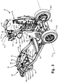
- FIG. 1A is a perspective front view of stand-on line striper 10 in which steering system 12 of the present disclosure is used.
- FIG. 1B is a top plan view of stand-on line striper 10 of FIG. 1A showing steering system 12, chassis 14, engine 16, hydraulic system 18 and paint system 19.
- Steering system 12 additionally includes forward and reverse speed controls.
- Paint system 19 comprises fluid pump 20, fluid container 21, spray guns 22A and 22B, actuators 23 ( FIG. 2 ), solenoids 24 ( FIG. 2 ) and controller 25.
- Steering system 12 includes handlebar 26, speed bar 28, steering cables 30A and 30B, centering device 32 and alignment system 34.
- Steering system 12 is coupled to power wheels 36A and 36B ( FIG. 1B ) and steering wheel 38.
- Hydraulic system 18 includes pump 40, motor 42 ( FIG. 2 ) and reservoir 44 ( FIG. 1B ). FIGS. 1A and 1B are discussed concurrently.
- Power wheels 36A and 36B and steering wheel 38 are mounted to chassis 14 so as to support line striper 10 and allow line striper 10 to roll under power from hydraulic system 18.
- Power wheels 36A and 36B are coupled to one or more hydraulic motors 42 ( FIG. 2 ) that receive motive fluid power from pump 40, which is driven by engine 16. Via cable 46, speed bar 28 regulates pump 40 to control fluid flow from reservoir 44 ( FIG. 1B ) to motors 42 ( FIG. 2 ).
- hydraulic system 18 operates as a hydrostatic propulsion system.
- Steering wheel 38 is connected to handlebar 26 of steering system 12 via cables 30A and 30B to rotate steering wheel 38 relative to chassis 14. Cables 30A and 30B are pushed and pulled by rotation of handlebar 26. Centering device 32 pulls steering wheel 38 to center when handlebar 26 is not subject to rotational force. Alignment system 34 adjusts the position of centering device 32 so as to allow for tuning of steering system 12, such as may be needed to accommodate stretching of cables 30A and 30B or wear of wheel 38.
- Engine 16 provides motive power to pump 40 of hydraulic system 18, which drives both wheels 36A and 36B and paint system 19.
- Fluid pump 20 receives an unpressurized fluid, such as paint, from fluid container 21 and provides pressurized fluid to spray guns 22A and 22B.
- fluid pump 20 comprises a hydraulically operated double-acting piston pump.
- Spray guns 22A and 22B are mechanically operated by hydraulic actuators 23 ( FIG. 2 ) that receive pressurized hydraulic fluid from hydraulic system 18. Hydraulic actuators 23 pull cables 48A and 48B to actuate spray guns 22A and 22B. Hydraulic actuators 23 are powered by solenoids 24 ( FIG. 2 ), which are electronically controlled by controller 25.
- Controller 25 comprises a computer system that is configured to operate spray guns 22A and 22B based on operator inputs.
- stand-on line striper 10 is configured to apply two parallel stripes of fluid from container 21 using spray guns 22A and 22B. Controller 25 controls when either or both of spray guns 22A and 22B are operated so that either one or two stripes are applied. Controller 25 also controls if the stripes are to be continuous or intermittent. If the stripes are to be intermittently applied, as specified by the operator, controller 25 controls the length of each stripe and the interval between stripes by controlling the length of time each spray gun is actuated. An operator of system 10 activates spray guns 22A and 22B with push-button 49 via controller 25, after setting desired parameters (e.g. single stripe, double stripe, stripe length, interval length) at controller 25.
- desired parameters e.g. single stripe, double stripe, stripe length, interval length
- FIG. 2 is a schematic view of hydraulic system 18 and paint system 19 of stand-on line striper 10 of FIGS. 1A and 1B interconnected with steering system 12. Hydraulic system 18 and paint system 19 are jointly operated by engine 16.
- engine 16 comprises a gas-operated internal combustion engine.
- Engine 16 provides direct mechanical input to pump 40 via a system of belts and pulleys (not shown).
- Hydraulic system 18 may, however, include multiple pumps driven by engine 16. For example, a first hydraulic pump may provide input to motors 42, while a second pump may provide input to fluid pump 20, with both pumps operating with fluid from reservoir 44. Pump 40 draws hydraulic fluid from reservoir 44, and hydraulic fluid from motors 42 ( FIG. 2 ) and pump 20 is returned to reservoir 44.
- engine 16 pump 40, motors 42, reservoir 44, wheels 36A and 36B and valve 50 comprise a hydrostatic system, as is known in the art.
- each of power wheels 36A and 36B may be provided with a dedicated motor served by pump 40.
- power wheel 36A is connected to motor 42A, as shown in FIG. 3 .
- Motors 42 are configured to provide both forward and aft motive power to wheels 36A and 36B.
- hydraulic system 18 utilizes reversing valve 50 with pump 40, as is known in the art, to reverse the direction of motors 42.
- Pump 40 (or another pump within system 18) additionally provides fluid power directly to fluid pump 20, which receives a fluid from container 21. Pump 40 pressurizes the fluid from container 21 and pumps the pressurized fluid to spray guns 22A and 22B.
- pump 20 comprises piston pump, such as the Viscount® 4-Ball piston pump commercially available from Graco Inc., Minneapolis, MN.
- Spray guns 22A and 22B are lever actuated nozzles that are connected to cables 48A and 48B. Cables 48A and 48B are mechanically pulled by actuators 23.
- Actuators 23 comprise hydraulic cylinders that are pressurized using high pressure hydraulic fluid bled from between pumps 40 and 20. Actuators 23 are activated using electric solenoids 24 that are powered and activated by controller 25.
- Controller 25 includes push-button 49 ( FIGS. 1A and 1B ), or some other activation switch, that send a signal from controller 25 to solenoids 24 to initiate activation of actuators 23, thus discharging fluid from spray guns 22A and 22B. As shown in FIGS. 1A and 1B , push-button 49 is conveniently located within steering system 12.
- Steering system 12 which includes handlebar 26 and speed bar 28 ( FIGS. 1A and 1B ), provides direct mechanical input to valve 50 and steering wheel 38.
- cables 30A and 30B extend from handlebar 26 to steering wheel 38, while cable 46 extends between speed bar 28 and valve 50 on pump 40.
- the hydrostatic system in order to apply stripes, such as to pavement or an athletic field, the hydrostatic system is engaged to provide motive force to power wheels 36A and 36B. As such, stand-on line striper 10 rolls along the surface to which stripes are to be applied. With line striper 10 moving, an operator utilizes steering system 12 to control the speed and direction of line striper 10. Once the operator positions line striper 10 into a place where painted stripes are to be applied, paint system 19 is activated by controller 25. Steering system 12 allows the operator to control activation of paint system 19, the speed of line striper 10 and the direction of line striper 10 with easy to use, intuitive controls, as is discussed with reference to FIGS. 3 - 4B .
- FIG. 3 is a perspective rear view of stand-on line striper 10 of FIGS. 1A and 1B with portions of hydraulic system 18 ( FIG. 1A ) and paint system 19 ( FIG. 1A ) removed to show steering system 12 connected to steering wheel 38.
- Chassis 14 provides a frame upon which the various systems of line striper 10 and wheels 36A, 36B and 38 are mounted.
- chassis 14 is fabricated from rectangular tubing bent into a rectilinear shape.
- Steering wheel 38 is mounted proximate a forward end of chassis 14 on post 51.
- Steering wheel 38 is positioned midway between the sides of chassis 14 in bar 52.
- Power wheels 36A and 36B are mounted proximate an aft end of chassis 14.
- power wheels 36A and 36B are mounted directly onto shafts from motors 42 ( FIG. 2 ).
- power wheel 36A can be mounted onto a shaft from motor 42A, as shown in FIG. 3 .
- power wheels 36A and 36B can be mounted onto spindles extending from chassis 14 and connected to motors 42 via gear systems.
- Centering device 32 includes spring 80 that applies force to carriage 58 to return steering wheel 38 to a "straight" position.
- Alignment system 34 includes guide 60 that slides on bar 52 to reorient centering device 32, as will be discussed in greater detail with reference to FIGS. 4A and 4B .
- Handlebar 26 and speed bar 28 are mounted on post 62, which is connected to chassis 14 through frame 64.
- Frame 64 provides a structure for mounting platform 65 upon which an operator of line striper 10 may stand.
- post 62 extends telescopically from stud 67 connected to frame 64 such that the height of handlebar 26 relative to platform 65 can be adjusted.
- an operator is positioned above power wheels 36A and 36B behind post 62, in position to grasp handlebar 26.
- Post 62 provides pivot point 63 for handlebar 26.
- Pivot point 63 extends along axis A1, which extends generally perpendicularly to both the plane of chassis 14 and axis A2 along which power wheels 36A and 36B rotate.
- An operator of line striper 10 can rotate handlebar 26 about axis A1 to control the position of steering wheel 38 via cables 30A and 30B.
- Speed bar 28 is connected to handle bar 26 at pivot point 66.
- Pivot point 66 extends along axis A3, which extends generally parallel to the plane of chassis 14 and perpendicular to axis A2.
- Cable 46 extends from speed bar 28 to valve 50 that controls output of hydraulic pump 40 to hydraulic motors 42 ( FIG. 2 ).
- Rotation of speed bar 28 in opposite directions causes forward or reverse movement of line striper 10.
- rotation of speed bar 28 about axis A3 in a counter-clockwise direction from center (as depicted) causes valve 50 to route hydraulic fluid through motors 42 in a direction that causes forward movement of line striper 10
- rotation of speed bar 28 about axis A3 in a clockwise direction from center (as depicted) causes valve 50 to route hydraulic fluid through motors 42 in a direction that causes rearward movement of line striper 10.
- Handlebar 26 includes handles that can be grasped to rotate handlebar about axis A1. As handlebar 26 is rotated cables 30A and 30B are pushed or pulled to rotate steering wheel 38. Cables 30A and 30B are cross-wired between handlebar 26 and wheel 38. Specifically, cable 30A extends from the right side of handlebar 26 to the left side of wheel 38, and cable 30B extends from the left side of handlebar 26 to the right side of wheel 38. Thus, for example, if handlebar 26 were rotated clockwise about axis A1, relative to the orientation of FIG. 3 , cable 30B would pull on the right side of wheel 38 while cable 30A would push on the left side of wheel 38, thereby causing wheel 38 to rotate clockwise.
- Cables 30A and 30B extend from fairing 68, are routed along post 62 and into frame 64 and turned back through chassis 14 to couple to carriage 58. Cables 30A and 30B extend within protective sleeves 71A and 71B, respectively, that are anchored to chassis 14 at flanges 70 and 72, thus facilitating pushing and pulling of the cables as handlebar 26 is rotated. Additionally, cables 30A and 30B include adjustable linkages that couple to carriage 58 and fairing 68. For example, cable 30B includes linkages 74B and 76B. Each linkage includes a threaded coupler that permits axial adjustment of the length of cable, and a ball joint that permits a swiveling fastening point.
- Fairing 68 is rigidly connected to handlebar 26 such that cables 30A and 30B rigidly connect handlebar 26 and carriage 58.
- rotation of handlebar 26 about axis A1 causes cables 30A and 30B to push and pull carriage 58.
- Cables 30A and 30B are sufficiently stiff such that each cable will push on carriage 58 when so moved.
- steering system 12 is operable with only one of cables 30A and 30B.
- the use of two cables provides redundancy, removes play from steering system 12 and facilitates re-centering of wheel 38.
- FIG. 4A is a close-up perspective view of a front portion of steering system 12 of FIG. 3 showing steering wheel 38, centering device 32 and alignment device 34 connected to chassis 14.
- FIG. 4B is a perspective view of steering system 12 of FIG. 4A showing steering wheel 38 and centering device 32 exploded from chassis 14.
- Centering device 32 includes caliper arms 78A and 78B, spring 80 and centering post 82.
- Alignment device 34 includes guide 60, stop post 84, flanges 86A and 86B attached to chassis 14, adjustment fastener 88 and stop fastener 90.
- Swivel post 51 of carriage 58 is inserted into socket 92 in bar 52 of frame 14.
- Steering wheel 38 which in one embodiment may comprise an inflatable tire, is connected to carriage 58 via shaft 93.
- Swivel post 51 may be provided with bearings 94A and 94B to facilitate rotation of carriage 58.
- Swivels 96A and 96B are connected to carriage 58 and provide rotatable joints for coupling with cables 30A and 30B. Cables 30A and 30B are anchored at flange 72 via collars 98A and 98B on sleeves 71A and 71B. Collar 98A and 98B are threaded onto cables 30A and 30B to adjust the length between flange 72 and carriage 58.
- Sleeves 71A and 71B are connected to flange 72 opposite collars 98A and 98B to provide a pathway for cables 30A and 30B to slide when moved by handlebar 26 ( FIG. 1A ).
- Caliper arms 78A and 78B include bores that are positioned around swivel post 51. Rearward extending portions of caliper arms 78A and 78B are linked by spring 80, and forward extending portions of caliper arms 78A and 78B squeeze centering post 82 and stop post 84 under force from the spring. Thus, caliper arms 78A and 78B operate as a scissor-type clamp. Stop post 84 is anchored to chassis 14 via alignment device 34.
- caliper arms 78A and 78B will rotate about swivel post 51 to align with stop post 84.
- Centering post 82 is also located between caliper arms 78A and 78B to bring carriage 58 into a center position tied to the position of stop post 84.
- centering post 82 is pushed by the spring action of caliper arms 78A and 78B toward alignment with stop post 84.
- centers of swivel post 51, stop post 84 and centering post 82 will be aligned along a straight line. Orientation of the straight line relative to chassis 14 can be controlled with alignment device 34.
- Guide 60 sits on bar 52 of chassis 14 and includes window 100 through which socket 92 extends. Guide 60 can slide upon bar 52 to adjust the position of stop post 84 relative to chassis 14. Movement of guide 60 can be precisely controlled using fastener 88 which extends through flanges 86A and 86B. For example, fastener 88 can be threaded into flange 86A to adjust the distance between flanges 86A and 86B in conjunction with a flange on fastener 88.
- Fastener 90 extends through a bore in guide 60 and a slot (not shown) in bar 52 in order to immobilize stop post 84 relative to chassis 14. Repositioning of stop post 84 adjusts the orientation of caliper arms 78A and 78B on swivel post 51, which then adjusts where caliper arms 78A and 78B push alignment post 82 under force of spring 80.
- the disclosure describes a self-propelled, stand-on cart upon which a line striping system can be mounted.
- the cart and line striping system are operated utilizing a control system that incorporates a steering system having ergonomic, easy-to-use controls.
- a handlebar can be positioned at a comfortable height for an operator to stand behind.
- the handlebar includes controls for paint, steering and propulsion systems such that painting, turning and speed controls are all accessible to an operator without lifting his or her hands from the handlebar.
- rotation of the handlebar provides intuitive steering control, while pivoting of a speed bar provides intuitive speed control, including forward and reverse movements.
- the paint system is easily operated using a push-button system mounted to the handlebar.
- An operator of the line striping system need not apply force to move or steer the cart, as it is self-propelled.
- an operator of the line striping system can apply more accurate stripes with less fatigue.
Abstract

Description
- The present disclosure relates generally to line striping systems, such as those used for applying painted stripes to roadways and athletic fields. More particularly, the present disclosure relates to control systems for self-propelled line striping systems.
- Line striping systems typically comprise carts that include a gas-operated engine that drives a pump. The pump is fed a liquid, such as paint, from a container disposed on the cart and supplies pressurized fluid to spray nozzles mounted so as to discharge toward the ground. Conventional line striping systems comprise walk-behind carts that are pushed by the operator, who simultaneously operates the spray nozzles with levers mounted to a handlebar for the cart. Such a handlebar typically comprises a fixed pair of handles that are used to orientate swivel-mounted wheels at the front of the cart. These handlebars require the operator to manually actuate the spray nozzles to determine the length of each stripe and the interval between stripes, while physically pushing and turning the entire system.
- Line striping carts can be pushed by self-propelled trailers that attach to the rear of the carts, such as at a ball and socket hitch. Each trailer includes a gas-operated engine, separate from the pumping engine, that drives a hydrostatic propulsion system. An operator sits on the trailer and grasps the handlebar of the cart. The hydrostatic propulsion system is typically operated with foot pedals that leave hands of the operator free to manipulate the spray nozzle levers of the cart. In order to facilitate application of straight-line stripes, the front swivel-mounted wheels can be locked to promote straight-line movement of the cart. The pivot-point between the cart and the trailer at the hitch still allows for steering of the system by "wiggling" the cart relative to the trailer. These systems reduce operator fatigue, but still require operator judgment in applying the stripes and are bulky and difficult to maneuver.
- There is a continuing need to increase the accuracy of lines produced by the striping system, while at the same time reducing operator fatigue.
- The present disclosure is directed to spray systems, such as those that can be used as self-propelled line stripers. A line striping system comprises a chassis, wheels, a spray system, a propulsion system and a steering system. The wheels are mounted under the chassis. The spray system is mounted on the chassis. The propulsion system is mounted on the chassis to drive the wheels. The steering system is coupled to the chassis. The steering system comprises a handlebar rotatatable to steer a wheel, and a speed bar pivotable to control the propulsion system.
-
-
FIG. 1A is a perspective front view of a stand-on line striper in which a steering system of the present disclosure is used. -
FIG. 1B is a top plan view of the stand-on line striper ofFIG. 1A showing the steering system, a hydraulic system and a paint system. -
FIG. 2 is a schematic view of the hydraulic system and paint system of the stand-on line striper ofFIGS. 1A and1B interconnected with the steering system. -
FIG. 3 is a perspective rear view of the stand-on line striper ofFIGS. 1A and1B with parts of the hydraulic system and paint system removed to show the steering system connected to a steering wheel. -
FIG. 4A is a close-up perspective view of a front portion of the steering system ofFIG. 3 showing the steering wheel, a centering device and an alignment device connected to a chassis. -
FIG. 4B is a perspective view of the steering system ofFIG. 4A showing the steering wheel and the centering device exploded from the chassis. -
FIG. 1A is a perspective front view of stand-online striper 10 in whichsteering system 12 of the present disclosure is used.FIG. 1B is a top plan view of stand-online striper 10 ofFIG. 1A showingsteering system 12,chassis 14,engine 16,hydraulic system 18 andpaint system 19.Steering system 12 additionally includes forward and reverse speed controls.Paint system 19 comprisesfluid pump 20,fluid container 21,spray guns FIG. 2 ), solenoids 24 (FIG. 2 ) andcontroller 25.Steering system 12 includeshandlebar 26,speed bar 28,steering cables centering device 32 andalignment system 34.Steering system 12 is coupled topower wheels FIG. 1B ) andsteering wheel 38.Hydraulic system 18 includespump 40, motor 42 (FIG. 2 ) and reservoir 44 (FIG. 1B ).FIGS. 1A and1B are discussed concurrently. -
Power wheels steering wheel 38 are mounted tochassis 14 so as to supportline striper 10 and allowline striper 10 to roll under power fromhydraulic system 18.Power wheels FIG. 2 ) that receive motive fluid power frompump 40, which is driven byengine 16. Viacable 46,speed bar 28 regulatespump 40 to control fluid flow from reservoir 44 (FIG. 1B ) to motors 42 (FIG. 2 ). As such, in one embodiment,hydraulic system 18 operates as a hydrostatic propulsion system. -
Steering wheel 38 is connected tohandlebar 26 ofsteering system 12 viacables steering wheel 38 relative tochassis 14.Cables handlebar 26.Centering device 32pulls steering wheel 38 to center whenhandlebar 26 is not subject to rotational force.Alignment system 34 adjusts the position ofcentering device 32 so as to allow for tuning ofsteering system 12, such as may be needed to accommodate stretching ofcables wheel 38. -
Engine 16 provides motive power to pump 40 ofhydraulic system 18, which drives bothwheels paint system 19.Fluid pump 20 receives an unpressurized fluid, such as paint, fromfluid container 21 and provides pressurized fluid to sprayguns fluid pump 20 comprises a hydraulically operated double-acting piston pump.Spray guns FIG. 2 ) that receive pressurized hydraulic fluid fromhydraulic system 18.Hydraulic actuators 23pull cables spray guns Hydraulic actuators 23 are powered by solenoids 24 (FIG. 2 ), which are electronically controlled bycontroller 25. -
Controller 25 comprises a computer system that is configured to operatespray guns line striper 10 is configured to apply two parallel stripes of fluid fromcontainer 21 usingspray guns Controller 25 controls when either or both ofspray guns Controller 25 also controls if the stripes are to be continuous or intermittent. If the stripes are to be intermittently applied, as specified by the operator,controller 25 controls the length of each stripe and the interval between stripes by controlling the length of time each spray gun is actuated. An operator ofsystem 10 activatesspray guns button 49 viacontroller 25, after setting desired parameters (e.g. single stripe, double stripe, stripe length, interval length) atcontroller 25. -
FIG. 2 is a schematic view ofhydraulic system 18 andpaint system 19 of stand-online striper 10 ofFIGS. 1A and1B interconnected withsteering system 12.Hydraulic system 18 andpaint system 19 are jointly operated byengine 16. In one embodiment,engine 16 comprises a gas-operated internal combustion engine.Engine 16 provides direct mechanical input to pump 40 via a system of belts and pulleys (not shown).Hydraulic system 18 may, however, include multiple pumps driven byengine 16. For example, a first hydraulic pump may provide input tomotors 42, while a second pump may provide input tofluid pump 20, with both pumps operating with fluid fromreservoir 44.Pump 40 draws hydraulic fluid fromreservoir 44, and hydraulic fluid from motors 42 (FIG. 2 ) and pump 20 is returned toreservoir 44. - In one embodiment,
engine 16, pump 40,motors 42,reservoir 44,wheels valve 50 comprise a hydrostatic system, as is known in the art. Although only onemotor 42 is shown inFIG. 2 , each ofpower wheels pump 40. For example,power wheel 36A is connected tomotor 42A, as shown inFIG. 3 .Motors 42 are configured to provide both forward and aft motive power towheels hydraulic system 18 utilizes reversingvalve 50 withpump 40, as is known in the art, to reverse the direction ofmotors 42. - Pump 40 (or another pump within system 18) additionally provides fluid power directly to
fluid pump 20, which receives a fluid fromcontainer 21.Pump 40 pressurizes the fluid fromcontainer 21 and pumps the pressurized fluid tospray guns Spray guns cables Cables actuators 23.Actuators 23 comprise hydraulic cylinders that are pressurized using high pressure hydraulic fluid bled from betweenpumps Actuators 23 are activated usingelectric solenoids 24 that are powered and activated bycontroller 25.Controller 25 includes push-button 49 (FIGS. 1A and1B ), or some other activation switch, that send a signal fromcontroller 25 tosolenoids 24 to initiate activation ofactuators 23, thus discharging fluid fromspray guns FIGS. 1A and1B , push-button 49 is conveniently located within steeringsystem 12. -
Steering system 12, which includeshandlebar 26 and speed bar 28 (FIGS. 1A and1B ), provides direct mechanical input tovalve 50 andsteering wheel 38. Specifically,cables handlebar 26 tosteering wheel 38, whilecable 46 extends betweenspeed bar 28 andvalve 50 onpump 40. - Returning to
FIGS. 1A and1B , in order to apply stripes, such as to pavement or an athletic field, the hydrostatic system is engaged to provide motive force topower wheels line striper 10 rolls along the surface to which stripes are to be applied. Withline striper 10 moving, an operator utilizes steeringsystem 12 to control the speed and direction ofline striper 10. Once the operator positionsline striper 10 into a place where painted stripes are to be applied,paint system 19 is activated bycontroller 25.Steering system 12 allows the operator to control activation ofpaint system 19, the speed ofline striper 10 and the direction ofline striper 10 with easy to use, intuitive controls, as is discussed with reference toFIGS. 3 - 4B . -
FIG. 3 is a perspective rear view of stand-online striper 10 ofFIGS. 1A and1B with portions of hydraulic system 18 (FIG. 1A ) and paint system 19 (FIG. 1A ) removed to showsteering system 12 connected tosteering wheel 38. -
Chassis 14 provides a frame upon which the various systems ofline striper 10 andwheels chassis 14 is fabricated from rectangular tubing bent into a rectilinear shape.Steering wheel 38 is mounted proximate a forward end ofchassis 14 onpost 51.Steering wheel 38 is positioned midway between the sides ofchassis 14 inbar 52.Power wheels chassis 14. In one embodiment,power wheels FIG. 2 ). For example,power wheel 36A can be mounted onto a shaft frommotor 42A, as shown inFIG. 3 . In other embodiments,power wheels chassis 14 and connected tomotors 42 via gear systems. - Centering
device 32 includesspring 80 that applies force tocarriage 58 to returnsteering wheel 38 to a "straight" position.Alignment system 34 includesguide 60 that slides onbar 52 to reorient centeringdevice 32, as will be discussed in greater detail with reference toFIGS. 4A and4B . -
Handlebar 26 andspeed bar 28 are mounted onpost 62, which is connected tochassis 14 throughframe 64.Frame 64 provides a structure for mountingplatform 65 upon which an operator ofline striper 10 may stand. In one embodiment, post 62 extends telescopically fromstud 67 connected to frame 64 such that the height ofhandlebar 26 relative toplatform 65 can be adjusted. Thus, an operator is positioned abovepower wheels post 62, in position to grasphandlebar 26. -
Post 62 provides pivot point 63 forhandlebar 26. Pivot point 63 extends along axis A1, which extends generally perpendicularly to both the plane ofchassis 14 and axis A2 along whichpower wheels line striper 10 can rotatehandlebar 26 about axis A1 to control the position ofsteering wheel 38 viacables Speed bar 28 is connected to handlebar 26 atpivot point 66.Pivot point 66 extends along axis A3, which extends generally parallel to the plane ofchassis 14 and perpendicular to axis A2.Cable 46 extends fromspeed bar 28 tovalve 50 that controls output ofhydraulic pump 40 to hydraulic motors 42 (FIG. 2 ). Rotation ofspeed bar 28 in opposite directions causes forward or reverse movement ofline striper 10. For example, rotation ofspeed bar 28 about axis A3 in a counter-clockwise direction from center (as depicted) causesvalve 50 to route hydraulic fluid throughmotors 42 in a direction that causes forward movement ofline striper 10, while rotation ofspeed bar 28 about axis A3 in a clockwise direction from center (as depicted) causesvalve 50 to route hydraulic fluid throughmotors 42 in a direction that causes rearward movement ofline striper 10. -
Handlebar 26 includes handles that can be grasped to rotate handlebar about axis A1. Ashandlebar 26 is rotatedcables steering wheel 38.Cables handlebar 26 andwheel 38. Specifically,cable 30A extends from the right side ofhandlebar 26 to the left side ofwheel 38, andcable 30B extends from the left side ofhandlebar 26 to the right side ofwheel 38. Thus, for example, ifhandlebar 26 were rotated clockwise about axis A1, relative to the orientation ofFIG. 3 ,cable 30B would pull on the right side ofwheel 38 whilecable 30A would push on the left side ofwheel 38, thereby causingwheel 38 to rotate clockwise. -
Cables post 62 and intoframe 64 and turned back throughchassis 14 to couple tocarriage 58.Cables protective sleeves chassis 14 atflanges handlebar 26 is rotated. Additionally,cables carriage 58 andfairing 68. For example,cable 30B includeslinkages Fairing 68 is rigidly connected to handlebar 26 such thatcables handlebar 26 andcarriage 58. Thus, rotation ofhandlebar 26 about axis A1 causescables carriage 58.Cables carriage 58 when so moved. Thus, steeringsystem 12 is operable with only one ofcables system 12 and facilitates re-centering ofwheel 38. -
FIG. 4A is a close-up perspective view of a front portion ofsteering system 12 ofFIG. 3 showing steering wheel 38, centeringdevice 32 andalignment device 34 connected tochassis 14.FIG. 4B is a perspective view ofsteering system 12 ofFIG. 4A showingsteering wheel 38 and centeringdevice 32 exploded fromchassis 14. Centeringdevice 32 includescaliper arms spring 80 and centeringpost 82.Alignment device 34 includesguide 60, stoppost 84,flanges chassis 14,adjustment fastener 88 and stopfastener 90. -
Swivel post 51 ofcarriage 58 is inserted intosocket 92 inbar 52 offrame 14.Steering wheel 38, which in one embodiment may comprise an inflatable tire, is connected tocarriage 58 viashaft 93.Swivel post 51 may be provided withbearings carriage 58.Swivels carriage 58 and provide rotatable joints for coupling withcables Cables flange 72 viacollars sleeves Collar cables flange 72 andcarriage 58.Sleeves opposite collars cables FIG. 1A ). - As
handlebar 26 is rotated,cables carriage 58, which rotates withinsocket 92 onswivel post 51.Caliper arms swivel post 51. Rearward extending portions ofcaliper arms spring 80, and forward extending portions ofcaliper arms squeeze centering post 82 and stoppost 84 under force from the spring. Thus,caliper arms post 84 is anchored tochassis 14 viaalignment device 34. Thus,caliper arms stop post 84. Centeringpost 82 is also located betweencaliper arms carriage 58 into a center position tied to the position ofstop post 84. Specifically, centeringpost 82 is pushed by the spring action ofcaliper arms stop post 84. As such, centers ofswivel post 51, stoppost 84 and centeringpost 82 will be aligned along a straight line. Orientation of the straight line relative tochassis 14 can be controlled withalignment device 34. -
Guide 60 sits onbar 52 ofchassis 14 and includeswindow 100 through whichsocket 92 extends.Guide 60 can slide uponbar 52 to adjust the position of stop post 84 relative tochassis 14. Movement ofguide 60 can be precisely controlled usingfastener 88 which extends throughflanges fastener 88 can be threaded intoflange 86A to adjust the distance betweenflanges fastener 88.Fastener 90 extends through a bore inguide 60 and a slot (not shown) inbar 52 in order to immobilize stop post 84 relative tochassis 14. Repositioning ofstop post 84 adjusts the orientation ofcaliper arms swivel post 51, which then adjusts wherecaliper arms alignment post 82 under force ofspring 80. - The disclosure describes a self-propelled, stand-on cart upon which a line striping system can be mounted. The cart and line striping system are operated utilizing a control system that incorporates a steering system having ergonomic, easy-to-use controls. For example, a handlebar can be positioned at a comfortable height for an operator to stand behind. The handlebar includes controls for paint, steering and propulsion systems such that painting, turning and speed controls are all accessible to an operator without lifting his or her hands from the handlebar. Additionally, rotation of the handlebar provides intuitive steering control, while pivoting of a speed bar provides intuitive speed control, including forward and reverse movements. The paint system is easily operated using a push-button system mounted to the handlebar. An operator of the line striping system need not apply force to move or steer the cart, as it is self-propelled. Thus, an operator of the line striping system can apply more accurate stripes with less fatigue.
- While the invention has been described with reference to an exemplary embodiment(s), it will be understood by those skilled in the art that various changes may be made and equivalents may be substituted for elements thereof without departing from the scope of the invention. In addition, many modifications may be made to adapt a particular situation or material to the teachings of the invention without departing from the essential scope thereof. Therefore, it is intended that the invention not be limited to the particular embodiment(s) disclosed, but that the invention will include all embodiments falling within the scope of the appended claims.
Claims (15)
- A self-propelled paint system comprising:a chassis;a first wheel mounted to the chassis;a second wheel mounted to the chassis;a hydraulic propulsion system mounted to the chassis, the hydraulicpropulsion system comprising:a hydraulic fluid; anda hydraulic motor driven by the hydraulic fluid and connected to the first wheel;a paint system mounted to the chassis, the paint system comprising:a paint pump powered by the hydraulic fluid; andsprayers fluidly coupled to the paint pump; anda steering system comprising:a steering lever rotatable about a first axis to move the second wheel; anda control lever mounted to the steering lever to control flow of the hydraulic fluid to the hydraulic motor.
- The self-propelled paint system of claim 1 wherein:the second wheel comprises:a carriage having a swivel post connected to the chassis; anda tire mounted to the carriage; andthe steering system further comprises:a pair of linkages connecting the steering lever to the carriage.
- The self-propelled paint system of claim 2 wherein each of the pair of linkages comprises:a flexible cable extending between the steering lever and the carriage;a mechanism to adjust a length of the flexible cable; anda ball joint coupling the flexible cable to the carriage.
- The self-propelled paint system of any of claims 1 to 3 wherein the steering system includes an activation switch configured to discharge fluid from the sprayers.
- The self-propelled paint system of any of claims 1 to 4 wherein the steering system includes a push-button mounted on the steering lever, the push-button being configured to discharge fluid from the sprayers.
- The self-propelled paint system of any of claims 1 to 5 wherein the steering lever and the control lever are mounted on an adjustable post.
- The self-propelled paint system of claim 6 wherein the post extends telescopically such that the height of the steering lever relative to a platform of the chassis can be adjusted.
- The self-propelled paint system of any of claims 1 to 7 wherein the control lever is rotatable about a second axis, the second axis being perpendicular to the first axis.
- The self-propelled paint system of claim 8 wherein rotation of the control lever about the second axis in a counter-clockwise direction causes forward movement of the self-propelled paint system and rotation of the control lever about the second axis in a clockwise direction causes rearward movement of the self-propelled paint system.
- The self-propelled paint system of any of claims 1 to 8 wherein rotation of the control lever in opposite directions causes forward or reverse movement of the self-propelled paint system.
- The self-propelled paint system of claim 8 or claim 9 wherein the first axis extends generally perpendicularly to a plane of the chassis and the second axis extends generally parallel to the plane of the chassis.
- The self-propelled paint system of any of claims 1 to 11 wherein the steering lever includes controls for the paint system, the steering system, and hydraulic propulsion system.
- The self-propelled paint system of any of claims 8, 9 and 11 and further comprising a pivot-point joining the control lever to the steering lever, the pivot-point extending along the second axis.
- The self-propelled paint system of any of claims 1, 4-7, 10, and 12, wherein:the first wheel is a drive wheel coupled to an aft end of the chassis;the second wheel is a swivel wheel mounted to a forward end of the chassis at a swivel;the hydraulic propulsion system further includes:a hydraulic pump for pressurizing hydraulic fluid; anda valve for controlling flow of hydraulic fluid from the hydraulic pump to the hydraulic motor; andthe steering system further includes:a cable extending from the steering lever to the swivel wheel; anda cable extending from the control lever to the valve;wherein the control lever is rotatable about a second axis.
- The self-propelled paint system of any of claims 1, 2-3, and 11-12, wherein:the steering system further includes:a push-button mounted on the steering lever and configured to activate the paint system; andwherein the control lever is mounted to the steering lever at a pivot-point extending along a second axis, the second axis being perpendicular to the first axis and the control lever being pivotable about the second axis to control the propulsion system;wherein the steering lever and the control lever are mounted on a post, the post providing a second pivot-point about which the steering lever rotates and the post being configured to extend telescopically such that the height of the steering lever relative to a platform of the chassis can be adjusted; andwherein pivoting of the control lever about the second axis in a counter-clockwise direction causes forward moving of the self-propelled paint system and pivoting of the control lever about the second axis in a clockwise direction causes rearward movement of the self-propelled paint system.
Applications Claiming Priority (3)
| Application Number | Priority Date | Filing Date | Title |
|---|---|---|---|
| US201261645268P | 2012-05-10 | 2012-05-10 | |
| PCT/US2013/040371 WO2013170047A1 (en) | 2012-05-10 | 2013-05-09 | Control system for self-propelled line striper |
| EP13788279.1A EP2847386B1 (en) | 2012-05-10 | 2013-05-09 | Control system for self-propelled line striper |
Related Parent Applications (2)
| Application Number | Title | Priority Date | Filing Date |
|---|---|---|---|
| EP13788279.1A Division EP2847386B1 (en) | 2012-05-10 | 2013-05-09 | Control system for self-propelled line striper |
| EP13788279.1A Division-Into EP2847386B1 (en) | 2012-05-10 | 2013-05-09 | Control system for self-propelled line striper |
Publications (2)
| Publication Number | Publication Date |
|---|---|
| EP3312342A1 true EP3312342A1 (en) | 2018-04-25 |
| EP3312342B1 EP3312342B1 (en) | 2021-10-13 |
Family
ID=49551282
Family Applications (2)
| Application Number | Title | Priority Date | Filing Date |
|---|---|---|---|
| EP13788279.1A Active EP2847386B1 (en) | 2012-05-10 | 2013-05-09 | Control system for self-propelled line striper |
| EP17202177.6A Active EP3312342B1 (en) | 2012-05-10 | 2013-05-09 | Control system for self-propelled line striper |
Family Applications Before (1)
| Application Number | Title | Priority Date | Filing Date |
|---|---|---|---|
| EP13788279.1A Active EP2847386B1 (en) | 2012-05-10 | 2013-05-09 | Control system for self-propelled line striper |
Country Status (6)
| Country | Link |
|---|---|
| US (3) | US9695557B2 (en) |
| EP (2) | EP2847386B1 (en) |
| CN (1) | CN104285008B (en) |
| AU (1) | AU2013259452B2 (en) |
| IN (1) | IN2014DN09686A (en) |
| WO (1) | WO2013170047A1 (en) |
Families Citing this family (15)
| Publication number | Priority date | Publication date | Assignee | Title |
|---|---|---|---|---|
| WO2013170047A1 (en) | 2012-05-10 | 2013-11-14 | Graco Minnesota Inc. | Control system for self-propelled line striper |
| WO2016126635A1 (en) | 2015-02-03 | 2016-08-11 | Wagner Spray Tech Corporation | Line striper with deployable sweeper |
| EP3495559B1 (en) | 2016-01-20 | 2022-04-20 | Graco Minnesota Inc. | Line striping machine with a clamp for mounting on a mounting arm and method of operating the line striper |
| EP3196359B1 (en) * | 2016-01-20 | 2018-08-01 | Graco Minnesota Inc. | Line striper with guided wheel assembly alignment and alignment method |
| EP3658710B1 (en) | 2017-07-27 | 2021-08-04 | Swozi Ag | Line marking device and method for marking a line |
| CN107620250A (en) * | 2017-09-28 | 2018-01-23 | 南通威而多专用汽车制造有限公司 | Pen machine boost motor |
| CN107604803A (en) * | 2017-09-28 | 2018-01-19 | 南通威而多专用汽车制造有限公司 | Pen machine boost motor with illumination functions |
| US10669679B2 (en) * | 2018-02-26 | 2020-06-02 | Graco Minnesota Inc. | Ground striper pump piston having dual checks |
| US10828656B2 (en) | 2018-07-27 | 2020-11-10 | Avant-Garde Ip Llc | Height and rotational adjustment system for one or more spray guns used in a line striper |
| US11148161B2 (en) * | 2018-07-27 | 2021-10-19 | Avant-Garde Ip Llc | Height adjustment system for one or more spray guns used in a line striper |
| US11051450B2 (en) | 2018-11-09 | 2021-07-06 | The Toro Company | Walk reel mower with a telescopic handle assembly |
| USD934301S1 (en) * | 2019-03-08 | 2021-10-26 | Graco Minnesota Inc. | Pump unit |
| USD934918S1 (en) * | 2019-03-08 | 2021-11-02 | Graco Minnesota Inc. | Pump unit |
| CN112779847B (en) * | 2021-01-12 | 2022-08-19 | 华仁建设集团有限公司 | Marking device is used in building site construction |
| JP6918266B1 (en) * | 2021-06-17 | 2021-08-11 | 芳徳 川崎 | Bicycle type line pulling device |
Citations (5)
| Publication number | Priority date | Publication date | Assignee | Title |
|---|---|---|---|---|
| FR1043766A (en) * | 1951-10-12 | 1953-11-12 | Soc D Const De Materiel Routie | Printing machine on the floor |
| FR2746823A1 (en) * | 1996-03-29 | 1997-10-03 | Euroliners | Road marking machine for urban or rural use |
| US7478689B1 (en) * | 2006-03-21 | 2009-01-20 | Scag Power Equipment, Inc. | Vehicle steering and speed control |
| US7611076B1 (en) * | 2004-05-19 | 2009-11-03 | The Toro Company | Line marker with reservoir drain into paint bucket and mult-position spray nozzle with a rear spray position |
| WO2009137068A1 (en) * | 2008-05-06 | 2009-11-12 | Graco Minnesota, Inc. | Striper with adjustable handle |
Family Cites Families (23)
| Publication number | Priority date | Publication date | Assignee | Title |
|---|---|---|---|---|
| GB497932A (en) | 1937-06-26 | 1938-12-28 | Frank Morrish | Improvements in or relating to painting machines for laying coloured lines and various markings on roads, hard courts, parking grounds and the like |
| CH326093A (en) | 1954-04-27 | 1957-12-15 | Ehrismann Robert | Method and device for applying markings on streets, parking lots and the like |
| US3052077A (en) * | 1958-09-12 | 1962-09-04 | Gustafson | Line marking machine |
| US3540632A (en) * | 1968-12-16 | 1970-11-17 | Andrew J Clingan | Fixedly directed hand operated striping machine with attachment for facilitating maneuverability |
| US4267973A (en) * | 1978-01-27 | 1981-05-19 | Stewart James J | Parking lot and highway safety line painting machine |
| US4624602A (en) * | 1984-10-26 | 1986-11-25 | Wagner Spray Tech Corporation | Parking lot line striper |
| US4861190A (en) * | 1987-10-02 | 1989-08-29 | Glassel Brian D | Ride-on road stripers |
| US4867244A (en) * | 1987-11-16 | 1989-09-19 | Outboard Marine Corporation | Turf aerating apparatus |
| US5114268A (en) * | 1991-01-18 | 1992-05-19 | Mac Stripers, Inc. | Apparatus for applying a traffic stripe to a road |
| US5984031A (en) * | 1997-03-28 | 1999-11-16 | Wright Mfg., Inc. | Power mower with riding platform for supporting standing operator during operation |
| US5718534A (en) * | 1996-03-13 | 1998-02-17 | Fine Line Plastics Corp. | Rear drive ride-on tractor unit for propelling steerable utility vehicles such as walk-behind paint stripers |
| US5947637A (en) * | 1997-08-18 | 1999-09-07 | Neuling; William V. | Automatic tracking around curved patterns for paint stripers |
| US5947385A (en) | 1996-04-19 | 1999-09-07 | Graco Inc. | Vehicle towed apparatus for striping of roads |
| US6290428B1 (en) * | 1999-09-21 | 2001-09-18 | Allen M. Hall | Machine and method for dispensing a sealing compound |
| JP3735263B2 (en) * | 2001-03-16 | 2006-01-18 | 岡山ガード工機有限会社 | Drainage road marking coating structure and equipment |
| JP2005282249A (en) * | 2004-03-30 | 2005-10-13 | Sankei Kogyo:Kk | Road surface marking machine |
| AU2005269537B2 (en) * | 2004-07-26 | 2009-12-03 | Somero Enterprises, Inc. | Powered strike-off plow |
| US7325388B2 (en) | 2005-08-30 | 2008-02-05 | Wright Manufacturing, Inc. | Lawn mower with deck lift system that raises and lowers deck with respect to frame and handle control assembly |
| WO2013170047A1 (en) * | 2012-05-10 | 2013-11-14 | Graco Minnesota Inc. | Control system for self-propelled line striper |
| WO2013170058A1 (en) * | 2012-05-10 | 2013-11-14 | Graco Minnesota Inc. | Electro-hydraulic actuated spray guns |
| EP2920368B1 (en) * | 2012-10-17 | 2018-02-07 | Watson, Diane Lee | Vehicle for line marking |
| US9644331B2 (en) * | 2014-05-13 | 2017-05-09 | Laserline Mfg., Inc. | Paint-striping laser guidance system and related technology |
| US9920493B2 (en) * | 2015-07-06 | 2018-03-20 | Bruce Provost | Articulating fluid application device and method |
-
2013
- 2013-05-09 WO PCT/US2013/040371 patent/WO2013170047A1/en active Application Filing
- 2013-05-09 EP EP13788279.1A patent/EP2847386B1/en active Active
- 2013-05-09 CN CN201380024467.3A patent/CN104285008B/en active Active
- 2013-05-09 IN IN9686DEN2014 patent/IN2014DN09686A/en unknown
- 2013-05-09 US US14/400,197 patent/US9695557B2/en active Active
- 2013-05-09 EP EP17202177.6A patent/EP3312342B1/en active Active
- 2013-05-09 AU AU2013259452A patent/AU2013259452B2/en active Active
-
2017
- 2017-06-21 US US15/629,408 patent/US10087590B2/en active Active
-
2018
- 2018-09-26 US US16/143,203 patent/US10563364B2/en active Active
Patent Citations (5)
| Publication number | Priority date | Publication date | Assignee | Title |
|---|---|---|---|---|
| FR1043766A (en) * | 1951-10-12 | 1953-11-12 | Soc D Const De Materiel Routie | Printing machine on the floor |
| FR2746823A1 (en) * | 1996-03-29 | 1997-10-03 | Euroliners | Road marking machine for urban or rural use |
| US7611076B1 (en) * | 2004-05-19 | 2009-11-03 | The Toro Company | Line marker with reservoir drain into paint bucket and mult-position spray nozzle with a rear spray position |
| US7478689B1 (en) * | 2006-03-21 | 2009-01-20 | Scag Power Equipment, Inc. | Vehicle steering and speed control |
| WO2009137068A1 (en) * | 2008-05-06 | 2009-11-12 | Graco Minnesota, Inc. | Striper with adjustable handle |
Also Published As
| Publication number | Publication date |
|---|---|
| CN104285008B (en) | 2016-11-02 |
| AU2013259452A1 (en) | 2015-01-15 |
| US9695557B2 (en) | 2017-07-04 |
| EP3312342B1 (en) | 2021-10-13 |
| US20150136020A1 (en) | 2015-05-21 |
| IN2014DN09686A (en) | 2015-07-31 |
| EP2847386A4 (en) | 2016-03-16 |
| WO2013170047A1 (en) | 2013-11-14 |
| US20170284041A1 (en) | 2017-10-05 |
| US10087590B2 (en) | 2018-10-02 |
| US10563364B2 (en) | 2020-02-18 |
| CN104285008A (en) | 2015-01-14 |
| US20190024330A1 (en) | 2019-01-24 |
| AU2013259452B2 (en) | 2018-03-01 |
| EP2847386A1 (en) | 2015-03-18 |
| EP2847386B1 (en) | 2018-01-31 |
Similar Documents
| Publication | Publication Date | Title |
|---|---|---|
| US10563364B2 (en) | Control system for self-propelled line striper | |
| AU2017268530B2 (en) | Line striping systems | |
| US5718534A (en) | Rear drive ride-on tractor unit for propelling steerable utility vehicles such as walk-behind paint stripers | |
| US5302207A (en) | Line striper apparatus with optical sighting means | |
| EP3196358B1 (en) | Line striper with spray control system | |
| US10000230B2 (en) | Vehicle for line marking | |
| CN101754711B (en) | floor finish applicator | |
| US7237783B2 (en) | Accessory cart for striping pavement and other surfaces | |
| US5125764A (en) | Vehicle for applying and spreading surface coating material to roadway surfaces | |
| US7857239B2 (en) | Self-propelled walking spray boom | |
| US20230292732A1 (en) | Ground marking control for ground treatment vehicle and method of operating same | |
| EP2342381A1 (en) | Hybrid line marking apparatus |
Legal Events
| Date | Code | Title | Description |
|---|---|---|---|
| PUAI | Public reference made under article 153(3) epc to a published international application that has entered the european phase |
Free format text: ORIGINAL CODE: 0009012 |
|
| STAA | Information on the status of an ep patent application or granted ep patent |
Free format text: STATUS: THE APPLICATION HAS BEEN PUBLISHED |
|
| AC | Divisional application: reference to earlier application |
Ref document number: 2847386 Country of ref document: EP Kind code of ref document: P |
|
| AK | Designated contracting states |
Kind code of ref document: A1 Designated state(s): AL AT BE BG CH CY CZ DE DK EE ES FI FR GB GR HR HU IE IS IT LI LT LU LV MC MK MT NL NO PL PT RO RS SE SI SK SM TR |
|
| RIN1 | Information on inventor provided before grant (corrected) |
Inventor name: LINS, CHRISTOPHER A. Inventor name: MATTSON, BARRY W. Inventor name: MULGREW, BRIAN M. Inventor name: TRIPLETT, THOMAS L. Inventor name: KUCZENSKI, STEVEN R. Inventor name: SCHROEDER, JAMES C. Inventor name: RYDER, DOUGLAS S. |
|
| STAA | Information on the status of an ep patent application or granted ep patent |
Free format text: STATUS: REQUEST FOR EXAMINATION WAS MADE |
|
| 17P | Request for examination filed |
Effective date: 20181025 |
|
| RBV | Designated contracting states (corrected) |
Designated state(s): AL AT BE BG CH CY CZ DE DK EE ES FI FR GB GR HR HU IE IS IT LI LT LU LV MC MK MT NL NO PL PT RO RS SE SI SK SM TR |
|
| STAA | Information on the status of an ep patent application or granted ep patent |
Free format text: STATUS: EXAMINATION IS IN PROGRESS |
|
| 17Q | First examination report despatched |
Effective date: 20190205 |
|
| GRAP | Despatch of communication of intention to grant a patent |
Free format text: ORIGINAL CODE: EPIDOSNIGR1 |
|
| STAA | Information on the status of an ep patent application or granted ep patent |
Free format text: STATUS: GRANT OF PATENT IS INTENDED |
|
| INTG | Intention to grant announced |
Effective date: 20200727 |
|
| RIN1 | Information on inventor provided before grant (corrected) |
Inventor name: SCHROEDER, JAMES C. Inventor name: TRIPLETT, THOMAS L. Inventor name: MULGREW, BRIAN M. Inventor name: KUCZENSKI, STEVEN R. Inventor name: RYDER, DOUGLAS S. Inventor name: MATTSON, BARRY W. Inventor name: LINS, CHRISTOPHER A. |
|
| GRAJ | Information related to disapproval of communication of intention to grant by the applicant or resumption of examination proceedings by the epo deleted |
Free format text: ORIGINAL CODE: EPIDOSDIGR1 |
|
| STAA | Information on the status of an ep patent application or granted ep patent |
Free format text: STATUS: EXAMINATION IS IN PROGRESS |
|
| GRAP | Despatch of communication of intention to grant a patent |
Free format text: ORIGINAL CODE: EPIDOSNIGR1 |
|
| STAA | Information on the status of an ep patent application or granted ep patent |
Free format text: STATUS: GRANT OF PATENT IS INTENDED |
|
| INTC | Intention to grant announced (deleted) | ||
| INTG | Intention to grant announced |
Effective date: 20201218 |
|
| GRAJ | Information related to disapproval of communication of intention to grant by the applicant or resumption of examination proceedings by the epo deleted |
Free format text: ORIGINAL CODE: EPIDOSDIGR1 |
|
| STAA | Information on the status of an ep patent application or granted ep patent |
Free format text: STATUS: EXAMINATION IS IN PROGRESS |
|
| GRAP | Despatch of communication of intention to grant a patent |
Free format text: ORIGINAL CODE: EPIDOSNIGR1 |
|
| STAA | Information on the status of an ep patent application or granted ep patent |
Free format text: STATUS: GRANT OF PATENT IS INTENDED |
|
| INTC | Intention to grant announced (deleted) | ||
| INTG | Intention to grant announced |
Effective date: 20210429 |
|
| GRAS | Grant fee paid |
Free format text: ORIGINAL CODE: EPIDOSNIGR3 |
|
| GRAA | (expected) grant |
Free format text: ORIGINAL CODE: 0009210 |
|
| STAA | Information on the status of an ep patent application or granted ep patent |
Free format text: STATUS: THE PATENT HAS BEEN GRANTED |
|
| AC | Divisional application: reference to earlier application |
Ref document number: 2847386 Country of ref document: EP Kind code of ref document: P |
|
| AK | Designated contracting states |
Kind code of ref document: B1 Designated state(s): AL AT BE BG CH CY CZ DE DK EE ES FI FR GB GR HR HU IE IS IT LI LT LU LV MC MK MT NL NO PL PT RO RS SE SI SK SM TR |
|
| REG | Reference to a national code |
Ref country code: GB Ref legal event code: FG4D |
|
| REG | Reference to a national code |
Ref country code: CH Ref legal event code: EP |
|
| REG | Reference to a national code |
Ref country code: DE Ref legal event code: R096 Ref document number: 602013079674 Country of ref document: DE |
|
| REG | Reference to a national code |
Ref country code: IE Ref legal event code: FG4D |
|
| REG | Reference to a national code |
Ref country code: AT Ref legal event code: REF Ref document number: 1438277 Country of ref document: AT Kind code of ref document: T Effective date: 20211115 |
|
| REG | Reference to a national code |
Ref country code: LT Ref legal event code: MG9D |
|
| REG | Reference to a national code |
Ref country code: NL Ref legal event code: MP Effective date: 20211013 |
|
| REG | Reference to a national code |
Ref country code: AT Ref legal event code: MK05 Ref document number: 1438277 Country of ref document: AT Kind code of ref document: T Effective date: 20211013 |
|
| PG25 | Lapsed in a contracting state [announced via postgrant information from national office to epo] |
Ref country code: RS Free format text: LAPSE BECAUSE OF FAILURE TO SUBMIT A TRANSLATION OF THE DESCRIPTION OR TO PAY THE FEE WITHIN THE PRESCRIBED TIME-LIMIT Effective date: 20211013 Ref country code: LT Free format text: LAPSE BECAUSE OF FAILURE TO SUBMIT A TRANSLATION OF THE DESCRIPTION OR TO PAY THE FEE WITHIN THE PRESCRIBED TIME-LIMIT Effective date: 20211013 Ref country code: FI Free format text: LAPSE BECAUSE OF FAILURE TO SUBMIT A TRANSLATION OF THE DESCRIPTION OR TO PAY THE FEE WITHIN THE PRESCRIBED TIME-LIMIT Effective date: 20211013 Ref country code: BG Free format text: LAPSE BECAUSE OF FAILURE TO SUBMIT A TRANSLATION OF THE DESCRIPTION OR TO PAY THE FEE WITHIN THE PRESCRIBED TIME-LIMIT Effective date: 20220113 Ref country code: AT Free format text: LAPSE BECAUSE OF FAILURE TO SUBMIT A TRANSLATION OF THE DESCRIPTION OR TO PAY THE FEE WITHIN THE PRESCRIBED TIME-LIMIT Effective date: 20211013 |
|
| PG25 | Lapsed in a contracting state [announced via postgrant information from national office to epo] |
Ref country code: IS Free format text: LAPSE BECAUSE OF FAILURE TO SUBMIT A TRANSLATION OF THE DESCRIPTION OR TO PAY THE FEE WITHIN THE PRESCRIBED TIME-LIMIT Effective date: 20220213 Ref country code: SE Free format text: LAPSE BECAUSE OF FAILURE TO SUBMIT A TRANSLATION OF THE DESCRIPTION OR TO PAY THE FEE WITHIN THE PRESCRIBED TIME-LIMIT Effective date: 20211013 Ref country code: PT Free format text: LAPSE BECAUSE OF FAILURE TO SUBMIT A TRANSLATION OF THE DESCRIPTION OR TO PAY THE FEE WITHIN THE PRESCRIBED TIME-LIMIT Effective date: 20220214 Ref country code: PL Free format text: LAPSE BECAUSE OF FAILURE TO SUBMIT A TRANSLATION OF THE DESCRIPTION OR TO PAY THE FEE WITHIN THE PRESCRIBED TIME-LIMIT Effective date: 20211013 Ref country code: NO Free format text: LAPSE BECAUSE OF FAILURE TO SUBMIT A TRANSLATION OF THE DESCRIPTION OR TO PAY THE FEE WITHIN THE PRESCRIBED TIME-LIMIT Effective date: 20220113 Ref country code: NL Free format text: LAPSE BECAUSE OF FAILURE TO SUBMIT A TRANSLATION OF THE DESCRIPTION OR TO PAY THE FEE WITHIN THE PRESCRIBED TIME-LIMIT Effective date: 20211013 Ref country code: LV Free format text: LAPSE BECAUSE OF FAILURE TO SUBMIT A TRANSLATION OF THE DESCRIPTION OR TO PAY THE FEE WITHIN THE PRESCRIBED TIME-LIMIT Effective date: 20211013 Ref country code: HR Free format text: LAPSE BECAUSE OF FAILURE TO SUBMIT A TRANSLATION OF THE DESCRIPTION OR TO PAY THE FEE WITHIN THE PRESCRIBED TIME-LIMIT Effective date: 20211013 Ref country code: GR Free format text: LAPSE BECAUSE OF FAILURE TO SUBMIT A TRANSLATION OF THE DESCRIPTION OR TO PAY THE FEE WITHIN THE PRESCRIBED TIME-LIMIT Effective date: 20220114 Ref country code: ES Free format text: LAPSE BECAUSE OF FAILURE TO SUBMIT A TRANSLATION OF THE DESCRIPTION OR TO PAY THE FEE WITHIN THE PRESCRIBED TIME-LIMIT Effective date: 20211013 |
|
| REG | Reference to a national code |
Ref country code: DE Ref legal event code: R097 Ref document number: 602013079674 Country of ref document: DE |
|
| PG25 | Lapsed in a contracting state [announced via postgrant information from national office to epo] |
Ref country code: SM Free format text: LAPSE BECAUSE OF FAILURE TO SUBMIT A TRANSLATION OF THE DESCRIPTION OR TO PAY THE FEE WITHIN THE PRESCRIBED TIME-LIMIT Effective date: 20211013 Ref country code: SK Free format text: LAPSE BECAUSE OF FAILURE TO SUBMIT A TRANSLATION OF THE DESCRIPTION OR TO PAY THE FEE WITHIN THE PRESCRIBED TIME-LIMIT Effective date: 20211013 Ref country code: RO Free format text: LAPSE BECAUSE OF FAILURE TO SUBMIT A TRANSLATION OF THE DESCRIPTION OR TO PAY THE FEE WITHIN THE PRESCRIBED TIME-LIMIT Effective date: 20211013 Ref country code: EE Free format text: LAPSE BECAUSE OF FAILURE TO SUBMIT A TRANSLATION OF THE DESCRIPTION OR TO PAY THE FEE WITHIN THE PRESCRIBED TIME-LIMIT Effective date: 20211013 Ref country code: DK Free format text: LAPSE BECAUSE OF FAILURE TO SUBMIT A TRANSLATION OF THE DESCRIPTION OR TO PAY THE FEE WITHIN THE PRESCRIBED TIME-LIMIT Effective date: 20211013 Ref country code: CZ Free format text: LAPSE BECAUSE OF FAILURE TO SUBMIT A TRANSLATION OF THE DESCRIPTION OR TO PAY THE FEE WITHIN THE PRESCRIBED TIME-LIMIT Effective date: 20211013 |
|
| PLBE | No opposition filed within time limit |
Free format text: ORIGINAL CODE: 0009261 |
|
| STAA | Information on the status of an ep patent application or granted ep patent |
Free format text: STATUS: NO OPPOSITION FILED WITHIN TIME LIMIT |
|
| 26N | No opposition filed |
Effective date: 20220714 |
|
| PG25 | Lapsed in a contracting state [announced via postgrant information from national office to epo] |
Ref country code: AL Free format text: LAPSE BECAUSE OF FAILURE TO SUBMIT A TRANSLATION OF THE DESCRIPTION OR TO PAY THE FEE WITHIN THE PRESCRIBED TIME-LIMIT Effective date: 20211013 |
|
| PG25 | Lapsed in a contracting state [announced via postgrant information from national office to epo] |
Ref country code: SI Free format text: LAPSE BECAUSE OF FAILURE TO SUBMIT A TRANSLATION OF THE DESCRIPTION OR TO PAY THE FEE WITHIN THE PRESCRIBED TIME-LIMIT Effective date: 20211013 |
|
| REG | Reference to a national code |
Ref country code: CH Ref legal event code: PL |
|
| REG | Reference to a national code |
Ref country code: BE Ref legal event code: MM Effective date: 20220531 |
|
| GBPC | Gb: european patent ceased through non-payment of renewal fee |
Effective date: 20220509 |
|
| PG25 | Lapsed in a contracting state [announced via postgrant information from national office to epo] |
Ref country code: MC Free format text: LAPSE BECAUSE OF FAILURE TO SUBMIT A TRANSLATION OF THE DESCRIPTION OR TO PAY THE FEE WITHIN THE PRESCRIBED TIME-LIMIT Effective date: 20211013 Ref country code: LU Free format text: LAPSE BECAUSE OF NON-PAYMENT OF DUE FEES Effective date: 20220509 Ref country code: LI Free format text: LAPSE BECAUSE OF NON-PAYMENT OF DUE FEES Effective date: 20220531 Ref country code: CH Free format text: LAPSE BECAUSE OF NON-PAYMENT OF DUE FEES Effective date: 20220531 |
|
| PG25 | Lapsed in a contracting state [announced via postgrant information from national office to epo] |
Ref country code: IE Free format text: LAPSE BECAUSE OF NON-PAYMENT OF DUE FEES Effective date: 20220509 |
|
| PG25 | Lapsed in a contracting state [announced via postgrant information from national office to epo] |
Ref country code: IT Free format text: LAPSE BECAUSE OF FAILURE TO SUBMIT A TRANSLATION OF THE DESCRIPTION OR TO PAY THE FEE WITHIN THE PRESCRIBED TIME-LIMIT Effective date: 20211013 Ref country code: GB Free format text: LAPSE BECAUSE OF NON-PAYMENT OF DUE FEES Effective date: 20220509 Ref country code: BE Free format text: LAPSE BECAUSE OF NON-PAYMENT OF DUE FEES Effective date: 20220531 |
|
| P01 | Opt-out of the competence of the unified patent court (upc) registered |
Effective date: 20230531 |
|
| PGFP | Annual fee paid to national office [announced via postgrant information from national office to epo] |
Ref country code: FR Payment date: 20230525 Year of fee payment: 11 Ref country code: DE Payment date: 20230530 Year of fee payment: 11 |
|
| PG25 | Lapsed in a contracting state [announced via postgrant information from national office to epo] |
Ref country code: HU Free format text: LAPSE BECAUSE OF FAILURE TO SUBMIT A TRANSLATION OF THE DESCRIPTION OR TO PAY THE FEE WITHIN THE PRESCRIBED TIME-LIMIT; INVALID AB INITIO Effective date: 20130509 |