EP3312116A1 - Yarn winding device and package rotation stopping method - Google Patents
Yarn winding device and package rotation stopping method Download PDFInfo
- Publication number
- EP3312116A1 EP3312116A1 EP17192831.0A EP17192831A EP3312116A1 EP 3312116 A1 EP3312116 A1 EP 3312116A1 EP 17192831 A EP17192831 A EP 17192831A EP 3312116 A1 EP3312116 A1 EP 3312116A1
- Authority
- EP
- European Patent Office
- Prior art keywords
- yarn
- package
- winding
- section
- traversing
- Prior art date
- Legal status (The legal status is an assumption and is not a legal conclusion. Google has not performed a legal analysis and makes no representation as to the accuracy of the status listed.)
- Granted
Links
- 238000004804 winding Methods 0.000 title claims abstract description 219
- 238000000034 method Methods 0.000 title claims description 44
- 238000005520 cutting process Methods 0.000 claims description 42
- 230000007246 mechanism Effects 0.000 claims description 22
- 238000001514 detection method Methods 0.000 claims description 11
- 238000011144 upstream manufacturing Methods 0.000 claims description 10
- 230000001276 controlling effect Effects 0.000 description 50
- 230000008569 process Effects 0.000 description 25
- 238000005304 joining Methods 0.000 description 24
- 230000002093 peripheral effect Effects 0.000 description 12
- 238000012545 processing Methods 0.000 description 11
- 238000004519 manufacturing process Methods 0.000 description 8
- 238000012806 monitoring device Methods 0.000 description 6
- 238000007796 conventional method Methods 0.000 description 5
- 238000012544 monitoring process Methods 0.000 description 5
- 238000010586 diagram Methods 0.000 description 4
- 230000007547 defect Effects 0.000 description 3
- 230000015572 biosynthetic process Effects 0.000 description 2
- 238000007664 blowing Methods 0.000 description 2
- 230000008859 change Effects 0.000 description 2
- 239000002184 metal Substances 0.000 description 2
- 230000015556 catabolic process Effects 0.000 description 1
- 238000010276 construction Methods 0.000 description 1
- 230000008602 contraction Effects 0.000 description 1
- 230000007423 decrease Effects 0.000 description 1
- 238000006731 degradation reaction Methods 0.000 description 1
- 238000007667 floating Methods 0.000 description 1
- 239000012530 fluid Substances 0.000 description 1
- 230000002452 interceptive effect Effects 0.000 description 1
- 238000012986 modification Methods 0.000 description 1
- 230000004048 modification Effects 0.000 description 1
- 230000003287 optical effect Effects 0.000 description 1
- 230000001105 regulatory effect Effects 0.000 description 1
- 230000004044 response Effects 0.000 description 1
- 239000000126 substance Substances 0.000 description 1
- 239000002699 waste material Substances 0.000 description 1
Images


Classifications
-
- B—PERFORMING OPERATIONS; TRANSPORTING
- B65—CONVEYING; PACKING; STORING; HANDLING THIN OR FILAMENTARY MATERIAL
- B65H—HANDLING THIN OR FILAMENTARY MATERIAL, e.g. SHEETS, WEBS, CABLES
- B65H54/00—Winding, coiling, or depositing filamentary material
- B65H54/02—Winding and traversing material on to reels, bobbins, tubes, or like package cores or formers
- B65H54/22—Automatic winding machines, i.e. machines with servicing units for automatically performing end-finding, interconnecting of successive lengths of material, controlling and fault-detecting of the running material and replacing or removing of full or empty cores
- B65H54/26—Automatic winding machines, i.e. machines with servicing units for automatically performing end-finding, interconnecting of successive lengths of material, controlling and fault-detecting of the running material and replacing or removing of full or empty cores having one or more servicing units moving along a plurality of fixed winding units
-
- B—PERFORMING OPERATIONS; TRANSPORTING
- B65—CONVEYING; PACKING; STORING; HANDLING THIN OR FILAMENTARY MATERIAL
- B65H—HANDLING THIN OR FILAMENTARY MATERIAL, e.g. SHEETS, WEBS, CABLES
- B65H51/00—Forwarding filamentary material
- B65H51/20—Devices for temporarily storing filamentary material during forwarding, e.g. for buffer storage
- B65H51/22—Reels or cages, e.g. cylindrical, with storing and forwarding surfaces provided by rollers or bars
-
- B—PERFORMING OPERATIONS; TRANSPORTING
- B65—CONVEYING; PACKING; STORING; HANDLING THIN OR FILAMENTARY MATERIAL
- B65H—HANDLING THIN OR FILAMENTARY MATERIAL, e.g. SHEETS, WEBS, CABLES
- B65H54/00—Winding, coiling, or depositing filamentary material
- B65H54/02—Winding and traversing material on to reels, bobbins, tubes, or like package cores or formers
- B65H54/28—Traversing devices; Package-shaping arrangements
-
- B—PERFORMING OPERATIONS; TRANSPORTING
- B65—CONVEYING; PACKING; STORING; HANDLING THIN OR FILAMENTARY MATERIAL
- B65H—HANDLING THIN OR FILAMENTARY MATERIAL, e.g. SHEETS, WEBS, CABLES
- B65H57/00—Guides for filamentary materials; Supports therefor
- B65H57/12—Tubes
-
- B—PERFORMING OPERATIONS; TRANSPORTING
- B65—CONVEYING; PACKING; STORING; HANDLING THIN OR FILAMENTARY MATERIAL
- B65H—HANDLING THIN OR FILAMENTARY MATERIAL, e.g. SHEETS, WEBS, CABLES
- B65H63/00—Warning or safety devices, e.g. automatic fault detectors, stop-motions ; Quality control of the package
-
- B—PERFORMING OPERATIONS; TRANSPORTING
- B65—CONVEYING; PACKING; STORING; HANDLING THIN OR FILAMENTARY MATERIAL
- B65H—HANDLING THIN OR FILAMENTARY MATERIAL, e.g. SHEETS, WEBS, CABLES
- B65H65/00—Securing material to cores or formers
-
- B—PERFORMING OPERATIONS; TRANSPORTING
- B65—CONVEYING; PACKING; STORING; HANDLING THIN OR FILAMENTARY MATERIAL
- B65H—HANDLING THIN OR FILAMENTARY MATERIAL, e.g. SHEETS, WEBS, CABLES
- B65H67/00—Replacing or removing cores, receptacles, or completed packages at paying-out, winding, or depositing stations
- B65H67/04—Arrangements for removing completed take-up packages and or replacing by cores, formers, or empty receptacles at winding or depositing stations; Transferring material between adjacent full and empty take-up elements
- B65H67/0405—Arrangements for removing completed take-up packages or for loading an empty core
-
- B—PERFORMING OPERATIONS; TRANSPORTING
- B65—CONVEYING; PACKING; STORING; HANDLING THIN OR FILAMENTARY MATERIAL
- B65H—HANDLING THIN OR FILAMENTARY MATERIAL, e.g. SHEETS, WEBS, CABLES
- B65H67/00—Replacing or removing cores, receptacles, or completed packages at paying-out, winding, or depositing stations
- B65H67/08—Automatic end-finding and material-interconnecting arrangements
- B65H67/081—Automatic end-finding and material-interconnecting arrangements acting after interruption of the winding process, e.g. yarn breakage, yarn cut or package replacement
-
- B—PERFORMING OPERATIONS; TRANSPORTING
- B65—CONVEYING; PACKING; STORING; HANDLING THIN OR FILAMENTARY MATERIAL
- B65H—HANDLING THIN OR FILAMENTARY MATERIAL, e.g. SHEETS, WEBS, CABLES
- B65H2701/00—Handled material; Storage means
- B65H2701/30—Handled filamentary material
- B65H2701/31—Textiles threads or artificial strands of filaments
Definitions
- the present invention relates to a yarn winding device including a winding unit in which a yarn accumulating device is arranged between a yarn supplying section and a winding section, and a package rotation stopping method implemented in the yarn winding device.
- a yarn winding device including a winding unit that pulls a yarn from a yarn supplying section and winds the yarn on a winding section to form a package is known in the art.
- a yarn accumulating device for temporarily accumulating a yarn is arranged between a yarn supplying section and a winding section of the winding unit.
- rotation of the package is stopped while the yarn is still continuous between the package and the yarn accumulating device. Then, the yarn between the package and the yarn accumulating device is cut with a clamp cutter of the doffing device, and formation of a new package is performed after the yarn from the yarn accumulating device is fixed to a new winding tube.
- the clamp cutter of the doffing device is attached to an arm that can be moved by a certain extent by way of expansion, contraction, and pivoting; however, the range in which the clamp cutter can hold or cut the yarn is limited.
- a stopping position of the yarn in the traversing area when the traversing drum is stopped varies every time. If the stopping position of the yarn is out of the range in which the clamp cutter can hold and cut the yarn, the doffing cannot be performed.
- a dedicated positioning member that can position the yarn at a position where the clamp cutter can cut and hold the yarn is provided.
- the positioning member has a width that is slightly longer than a traversing width.
- a yarn winding device includes a winding unit that pulls a yarn from a yarn supplying section and winds the yarn on a winding tub in a winding section to form a package; and a doffing device that doffs from the winding unit a package in which the winding has been completed.
- the winding unit includes a traversing drum that rotates while being in contact with the package and traverses the yarn while rotating the package; a yarn accumulating device arranged between the yarn supplying section and the winding section in a yarn travelling direction for temporarily accumulating the yarn; a yarn detecting section capable of detecting the yarn traversed by the traversing drum; and a controlling section that controls the traversing drum.
- the doffing device includes a yarn holding and cutting section capable of holding and cutting the yarn when the yarn between the package and the yarn accumulating device is at a predetermined position in a traversing area.
- the controlling section controls, when the winding of the yarn is completed, a rotation of the traversing drum based on an output of the yarn detecting section such that, when the yarn between the package and the yarn accumulating device is continuous, to stop the rotation of the package so that the yarn between the package and the yarn accumulating device stops at the predetermined position.
- a package rotation stopping method for stopping rotation of a package is implemented in a yarn winding device.
- the yarn winding device includes a winding unit that, after temporarily accumulating a yarn pulled from a yarn supplying section in a yarn accumulating device, forms a package by winding the yarn on a winding tube while traversing the yarn with a traversing drum that rotates while being in contact with the package; and a doffing device that doffs from the winding unit a package in which the winding has been completed and including a yarn holding and cutting section capable of holding and cutting the yarn when the yarn between the package and the yarn accumulating device is at a predetermined position in a traversing area.
- the package rotation stopping method includes a decelerating step of decelerating, when the winding of the yarn is completed, the traversing drum while the yarn between the package and the yarn accumulating device is continuous thereby decelerating the package; a yarn detecting step of detecting the yarn traversed by the traversing drum; and a yarn positioning step of controlling the traversing drum based on a detection result of the yarn obtained at the yarn detecting step to stop the rotation of the package so that the yarn between the package and the yarn accumulating device stops at the predetermined position.
- a yarn winding device includes a winding unit that pulls a yarn from a yarn supplying section and winds the yarn on a winding tube in a winding section to form a package; and a doffing device that doffs from the winding unit a package in which the winding has been completed.
- the winding unit includes a traversing drum that rotates while being in contact with the package and traverses the yarn while rotating the package; and a yarn accumulating device arranged between the yarn supplying section and the winding section in a yarn travelling direction for temporarily accumulating the yarn.
- the winding unit when the winding of the yarn is completed, stops the rotation of the package while the yarn between the package and the yarn accumulating device is continuous.
- the doffing device includes a yarn holding and cutting section capable of holding and cutting the yarn between the package and the yarn accumulating device; and an introducing mechanism arranged integrally with the yarn holding and cutting section and that introduces into the yarn holding and cutting section the yarn present in a traversing area between the package and the yarn accumulating device.
- the traversing drum is controlled based on the output of the yarn detecting section to stop the rotation of the package so that the yarn between the package and the yarn accumulating device stops at the predetermined position at which the yarn holding and cutting section of the doffing device can hold and cut the yarn. Therefore, the positioning member needs not be moved as in the conventional technique, so that the yarn holding and cutting section can be operated quickly after the package has stopped. As a result, the time required for the doffing can be shortened so that the production efficiency of the package can be improved.
- the controlling section controls the traversing drum while decelerating the traversing drum, and directly stops the rotation of the traversing drum so that the yarn between the package and the yarn accumulating device stops at the predetermined position.
- the controlling section after stopping the rotation of the traversing drum once, can rotate the traversing drum for a predetermined amount so that the yarn between the package and the yarn accumulating device stops at the predetermined position.
- the control of the traversing drum can be avoided from becoming complicated and the yarn can be stopped precisely at the predetermined position.
- the yarn winding device further includes a guiding member arranged upstream of the traversing drum but downstream of the yarn accumulating device in the yarn travelling direction for enclosing the yarn traversed by the traversing drum, and the yarn detecting section is arranged in the guiding member.
- the yarn detecting section can be arranged near the yarn without interfering with the yarn.
- a package rotation stopping method for stopping rotation of a package is implemented in a yarn winding device.
- the yarn winding device includes a winding unit that, after temporarily accumulating a yarn pulled from a yarn supplying section in a yarn accumulating device, forms a package by winding the yarn on a winding tube while traversing the yarn with a traversing drum that rotates while being in contact with the package; and a doffing device that doffs from the winding unit a package in which the winding has been completed and including a yarn holding and cutting section capable of holding and cutting the yarn when the yarn between the package and the yarn accumulating device is at a predetermined position in a traversing area.
- the package rotation stopping method includes a decelerating step of decelerating, when the winding of the yarn is completed, the traversing drum while the yarn between the package and the yarn accumulating device is continuous thereby decelerating the package; a yarn detecting step of detecting the yarn traversed by the traversing drum; and a yarn positioning step of controlling the traversing drum based on a detection result of the yarn obtained at the yarn detecting step to stop the rotation of the package so that the yarn between the package and the yarn accumulating device stops at the predetermined position.
- the traversing drum is controlled based on the detection result of the yarn obtained at the yarn detecting step to stop the rotation of the package so that the yarn between the package and the yarn accumulating device stops at the predetermined position at which the yarn holding and cutting section of the doffing device can hold and cut the yarn. Therefore, the positioning member needs not be moved as in the conventional technique, so that the yarn holding and cutting section can be operated quickly after the package has stopped. As a result, the time required for the doffing can be shortened so that the production efficiency of the package can be improved.
- the yarn detecting step is performed during the decelerating step.
- the yarn positioning step is performed at the end of the decelerating step so that when the decelerating step is completed, the rotation of the package is stopped in a state in which the yarn between the package and the yarn accumulating device is at the predetermined position.
- the yarn positioning step is performed after the decelerating step, and the traversing drum that was stopped once at the decelerating step is rotated only for a predetermined amount at the yarn positioning step.
- the yarn between the package and the yarn accumulating device can be stopped at the predetermined position with a relatively simple control.
- a yarn winding device includes a winding unit that pulls a yarn from a yarn supplying section and winds the yarn on a winding tube in a winding section to form a package; and a doffing device that doffs from the winding unit a package in which the winding has been completed.
- the winding unit includes a traversing drum that rotates while being in contact with the package and traverses the yarn while rotating the package; and a yarn accumulating device arranged between the yarn supplying section and the winding section in a yarn travelling direction for temporarily accumulating the yarn.
- the winding unit when the winding of the yarn is completed, stops the rotation of the package while the yarn between the package and the yarn accumulating device is continuous.
- the doffing device includes a yarn holding and cutting section capable of holding and cutting the yarn between the package and the yarn accumulating device; and an introducing mechanism arranged integrally with the yarn holding and cutting section and that introduces into the yarn holding and cutting section the yarn present in a traversing area between the package and the yarn accumulating device.
- the introducing mechanism that introduces into the yarn holding and cutting section the yarn present in the traversing area between the package and the yarn accumulating device is arranged integrally with the yarn holding and cutting section. Accordingly, when stopping the rotation of the package in which the winding has been completed, the yarn can be introduced into the yarn holding and cutting section by using the introducing mechanism even if the yarn between the package and the yarn accumulating device is anywhere in the traversing area. Therefore, the positioning member needs not be moved as in the conventional technique, so that the yarn holding and cutting section can be operated quickly after the package has stopped. As a result, the time required for the doffing can be shortened so that the production efficiency of the package can be improved.
- the introducing mechanism includes an introducing member in which is formed an introducing path for introducing the yarn into the yarn holding and cutting section; and a guiding lever that guides into the introducing path the yarn present in the traversing area.
- the yarn between the package and the yarn accumulating device can be surely introduced into the yarn holding and cutting section.
- the introducing path is formed in a central part of the introducing member in a traversing direction, and the guiding lever is arranged on either side of the introducing path.
- the yarn between the package and the yarn accumulating device can be more surely introduced into the yarn holding and cutting section.
- FIG. 1 is a front view of an automatic winder according to one embodiment of the present invention.
- an automatic winder 1 (yarn winding device of the present invention) includes a plurality of winding units 2 arranged along a predetermined arrangement direction (left-right direction in FIG. 1 ), a doffing device 3 capable of traveling along the arrangement direction, a bobbin supplying device 4 that supplies a yarn supplying bobbin B, and a machine-frame controlling device 5.
- a left-right direction in FIG. 1 is termed as "left-right direction", an up-down direction in FIG.
- up-down direction a front side in a direction orthogonal to the paper surface of FIG. 1 is termed as “front direction”
- back direction a back side in the direction orthogonal to the paper surface of FIG. 1
- the winding unit 2 unwinds a yarn Y from a yarn supplying bobbin B and winds the yarn Y on a winding tube Q (see FIG. 2 ) to form a package P.
- the doffing device 3 travels along the arrangement direction to the position of that winding unit 2. Then, the doffing device 3 doffs the package P, in which the winding of the yarn Y has been completed, from this winding unit 2, and sets an empty winding tube Q in its place.
- the bobbin supplying device 4 mounts a yarn supplying bobbin B on a conveying tray T and supplies the yarn supplying bobbin B supported by the conveying tray T to a desired one of the winding units 2.
- the machine-frame controlling device 5 controls an operation of each of the winding units 2, the doffing device 3, and the bobbin supplying device 4. An operator can centrally manage the winding units 2 by appropriately operating the machine-frame controlling device 5.
- FIG. 2 is a side view of the winding unit 2.
- the winding unit 2 includes a yarn supplying section 10 that supplies the yarn Y while unwinding the yarn Y wound on the yarn supplying bobbin B, a yarn processing section 20 that performs various processes on the yarn Y supplied from the yarn supplying section 10, a yarn accumulating device 30 that temporarily accumulates the yarn Y that has passed the yarn processing section 20, and a winding section 40 that winds the yarn Y on the winding tube Q while traversing the yarn Y from the yarn accumulating device 30 to form a package P.
- the yarn supplying section 10, the yarn processing section 20, the yarn accumulating device 30, and the winding section 40 are arranged in this order from bottom to top.
- upstream and downstream in a yarn travelling direction which is a direction in which the yarn travels from the yarn supplying section 10 to the winding section 40 after passing through the yarn processing section 20 and the yarn accumulating device 30, are simply called upstream and downstream, respectively.
- the yarn supplying section 10 includes a yarn unwinding assisting device 11 that assists the unwinding of the yarn Y when unwinding the yarn Y from the yarn supplying bobbin B held in an upright state by the conveying tray T.
- the yarn unwinding assisting device 11 controls a size of a balloon of the yarn Y unwound from the yarn supplying bobbin B to an appropriate size by using a regulating pipe 12 thereby preventing excessive increase of a tension of the yarn Y unwound from the yarn supplying bobbin B.
- the yarn supplying section 10 discharges the empty yarn supplying bobbin B and receives a new yarn supplying bobbin B from the bobbin supplying device 4.
- the yarn processing section 20 includes an upper yarn catching member 21, a yarn joining device 22, a lower yarn catching member 23, a tension applying device 24, a yarn monitoring device 25, and the like.
- the upper yarn catching member 21, the yarn joining device 22, the lower yarn catching member 23, the tension applying device 24, and the yarn monitoring device 25 are arranged in this order from upstream to downstream.
- the upper yarn catching member 21 is arranged near but upstream of the yarn joining device 22.
- the upper yarn catching member 21 is connected to a not-shown negative pressure source.
- the upper yarn catching member 21 can generate a suction airflow and suck and catch the yarn Y from the winding section 40.
- the upper yarn catching member 21 guides the caught yarn Y to the yarn joining device 22.
- the yarn joining device 22 performs the yarn joining of a discontinuous yarn Y.
- the yarn joining device 22 performs yarn joining of a yarn Y from the yarn supplying section 10 (lower yarn) and a yarn Y from the winding section 40 (upper yarn).
- the yarn joining device 22 is arranged at a position that is slightly retracted from a yarn path.
- the yarn joining device 22 joins yarn ends introduced thereinto by the upper yarn catching member 21 and the lower yarn catching member 23 so that the yarn Y becomes continuous.
- a device that uses fluid such as compressed air, or a mechanical device can be used as the yarn joining device 22.
- the lower yarn catching member 23 is arranged near but downstream of the yarn joining device 22.
- the lower yarn catching member 23 is connected to a not-shown negative pressure source.
- the lower yarn catching member 23 is a cylindrical member with an opening formed in a tip end part thereof.
- the lower yarn catching member 23 includes a driving section 23a.
- the driving section 23a drives the lower yarn catching member 23 so as to advance to and retreat from the yarn path.
- the lower yarn catching member 23 generates a suction airflow at the tip thereof when the tip is near the yarn path. Accordingly, a yarn end of the yarn Y from the yarn supplying bobbin B that is blown by a later-explained lower yarn blow-feeding member 26 is sucked and caught by the lower yarn catching member 23.
- the lower yarn catching member 23 can be configured to generate a suction airflow at the tip thereof to suck and remove fly-waste and the like that may be attached to the travelling yarn Y.
- the lower yarn catching member 23 introduces the yarn end into the yarn joining device 22 after moving away from the yarn path in a state in which it has caught the yarn end from the yarn supplying bobbin B.
- the tension applying device 24 applies a predetermined tension to the traveling yarn Y.
- the tension applying device 24 is a gate-type member having fixed comb teeth and movable comb teeth, and applies a predetermined resistance on the yarn Y when the yarn Y travels between the comb teeth.
- the movable comb teeth can be moved by, for example, a solenoid, to change a distance between the movable comb teeth and the fixed comb teeth.
- the tension applying device 24 can adjust the tension applied to the yarn Y.
- the configuration of the tension applying device 24 is not limited to the gate-type, and it can be a disk-type tension applying device, for example.
- the yarn monitoring device 25 includes the monitoring section 25a that detects a yarn defect such as slub or mixing of a foreign substance by monitoring a thickness and the like of the yarn Y with an appropriate sensor. Moreover, in the yarn monitoring device 25, the cutter 25b is arranged upstream of the monitoring section 25a. The cutter 25b cuts the yarn Y immediately when the monitoring section 25a detects a yarn defect.
- a yarn defect such as slub or mixing of a foreign substance by monitoring a thickness and the like of the yarn Y with an appropriate sensor.
- the cutter 25b is arranged upstream of the monitoring section 25a. The cutter 25b cuts the yarn Y immediately when the monitoring section 25a detects a yarn defect.
- the yarn processing section 20 includes the lower yarn blow-feeding member 26, an upper yarn blow-feeding member 27, and a yarn guiding member 28.
- the lower yarn blow-feeding member 26 is a cylindrical member arranged near but downstream of the yarn unwinding assisting device 11. By jetting compressed air, the lower yarn blow-feeding member 26 generates an air current that can blow and feed the yarn Y to the lower yarn catching member 23. Accordingly, when a yarn breakage has occurred or after the yarn supplying bobbin B has been replaced, the lower yarn blow-feeding member 26 operates whereby the yarn end from the yarn supplying bobbin B can be caught with the lower yarn catching member 23 and this yarn end can be introduced into the yarn joining device 22.
- an auxiliary blow-feeding member 13 is arranged in the yarn supplying section 10.
- the auxiliary blow-feeding member 13 is positioned right below the conveying tray T that is arranged in the yarn supplying section 10.
- the auxiliary blow-feeding member 13 jets compressed air inside the conveying tray T and the yarn supplying bobbin B both of which are hollow inside.
- the upper yarn blow-feeding member 27 is a cylindrical member arranged near but upstream of the yarn accumulating device 30. By jetting compressed air, the upper yarn blow-feeding member 27 generates an air current that can blow and feed a yarn end from the yarn accumulating device 30 to the upper yarn catching member 21.
- the yarn guiding member 28 is a cylindrical member that is curved and projects toward the front direction so as to detour around the yarn monitoring device 25, the tension applying device 24, the yarn joining device 22, and the like.
- An opening is formed at each of the longitudinal ends of the yarn guiding member 28. The opening on one end opposes an outlet of the upper yarn blow-feeding member 27, and the opening on the other end opposes the upper yarn catching member 21.
- a not-shown slit is formed in a back side of the yarn guiding member 28 over an entire length of the yarn guiding member 28 so that the yarn Y that passes inside the yarn guiding member 28 from the opening on one end to the opening on the other end can be taken out of the yarn guiding member 28.
- the upper yarn blow-feeding member 27 catches the yarn end from the yarn accumulating device 30 and blows the same to the inside of the yarn guiding member 28, pulls the yarn Y along the yarn guiding member 28, and causes the yarn Y to be caught by the upper yarn catching member 21. In this manner, the yarn Y from the yarn accumulating device 30 is blown and fed by the upper yarn blow-feeding member 27 and guided to the yarn joining device 22.
- the yarn accumulating device 30 is arranged between the yarn processing section 20 and the winding section 40 in the yarn travelling direction.
- the yarn accumulating device 30 pulls the yarn Y from the yarn supplying section 10, temporarily accumulates the pulled yarn Y and supplies the yarn Y to the winding section 40. Because of the yarn accumulating device 30, it is prevented that the variations in the tension of the yarn Y unwound from the yarn supplying bobbin B are transmitted to the winding section 40 side. As a result, the variations in the tension of the yarn Y supplied to the winding section 40 can be suppressed leading to formation of a good quality package P. Moreover, because of the yarn accumulating device 30, the winding of the yarn Y by the winding section 40 can be continued even while performing the yarn joining.
- the yarn accumulating device 30 includes a yarn accumulating roller 31 on which the yarn Y can be wound, and a roller driving motor 32 that rotationally drives the yarn accumulating roller 31.
- the roller driving motor 32 can rotate the yarn accumulating roller 31 in a winding direction of the yarn Y from the yarn supplying section 10 (normal rotation) and can rotate the yarn accumulating roller 31 in an opposite direction of the winding direction (reverse rotation).
- the yarn Y wound on the yarn accumulating roller 31 is pulled to the downstream via a pulling guide 35 arranged on a line that extends from a central axis of the yarn accumulating roller 31.
- the yarn accumulating roller 31 has a cylindrical shape and it is formed, for example, of metal.
- the tension is applied to the yarn Y on the upstream side of the yarn accumulating device 30.
- the yarn Y is unwound from the yarn supplying bobbin B and the yarn Y is wound around an outer peripheral surface 31a of the yarn accumulating roller 31 thereby accumulating the yarn Y.
- an end of the yarn accumulating roller 31 near the roller driving motor 32 will be called a base end and the opposite end will be called a tip end.
- a ring member 33 is arranged on the outer peripheral surface 31a of the yarn accumulating roller 31 on a tip of the tip end thereof.
- the ring member 33 has a circular shape and it is formed, for example, of rubber.
- the ring member 33 is fit on the outer peripheral surface 31a by an elastic force that acts inward in a radial direction of the ring member 33.
- the yarn Y is passed inside the ring member 33. Accordingly, a resistance is applied on the yarn Y pulled from the yarn accumulating roller 31 because of the elastic force of the ring member 33. Accordingly, an appropriate tension is applied to the yarn Y that is being pulled from the yarn accumulating roller 31 allowing the unwinding of the yarn Y from the yarn accumulating roller 31 to be performed in a stable manner.
- a groove 31b is formed in the outer peripheral surface 31a of the yarn accumulating roller 31 along an axial direction of the yarn accumulating roller 31 below the location of the ring member 33 as well.
- An urging member 36 that is biased outward in the radial direction by a not-shown spring is accommodated in a portion of the groove 31b that intersects with the ring member 33.
- This urging member 36 is forcefully pushed inward in the radial direction by a later-explained yarn passing nozzle 34.
- the yarn accumulating device 30 includes the cylindrical yarn passing nozzle 34.
- the yarn passing nozzle 34 is arranged near the yarn accumulating roller 31.
- One end of the yarn passing nozzle 34 is arranged so as to oppose the outer peripheral surface 31a of the yarn accumulating roller 31 on the tip of the tip end thereof.
- the yarn passing nozzle 34 is configured so that the compressed air can be passed inside thereof from the other end to the one end.
- the other end (the end that is on an opposite side of a side on which the yarn accumulating roller 31 is present) of the yarn passing nozzle 34 functions as a suction port that sucks the yarn Y
- the one end (the end that opposes the yarn accumulating roller 31) of the yarn passing nozzle 34 functions as a blowing port for blowing off the sucked yarn Y.
- the yarn passing nozzle 34 can be moved toward or away from the outer peripheral surface 31a of the yarn accumulating roller 31 by, for example, a sliding mechanism that uses an actuator such as an air cylinder or a motor.
- the yarn passing nozzle 34 When the yarn passing nozzle 34 is moved toward the outer peripheral surface 31a of the yarn accumulating roller 31 while the urging member 36 is opposing the one end of the yarn passing nozzle 34, the yarn passing nozzle 34 forcefully pushes the urging member 36 inward in the radial direction against the urging force of the spring, and a gap is formed between the ring member 33 and the urging member 36.
- the yarn end of the yarn Y that has passed from the tip end side to the base end side of the yarn accumulating roller 31 is further blown by the upper yarn blow-feeding member 27 to the yarn guiding member 28, caught by the upper yarn catching member 21, and guided to the yarn joining device 22.
- FIG. 3 is a front view of the winding section 40 of the winding unit 2.
- the winding section 40 includes a cradle 41 on which the winding tube Q can be mounted, a traversing drum 42 that rotates the winding tube Q or the package P while traversing the yarn Y, and a traversing guide 43 that guides the yarn Y traversed by the traversing drum 42.
- the cradle 41 includes a pair of left and right arms 41a and a pair of left and right holders 41b attached respectively in the inside of each of the arms 41a. Accordingly, the cradle 41 can rotatably support the winding tube Q or the package P with the holders 41b. The cradle 41 can cause an outer peripheral surface of the supported package P to contact an outer peripheral surface of the traversing drum 42.
- the traversing drum 42 is rotationally driven by a driving source 45 constituted by a motor and the like.
- the winding tube Q or the package P is rotatably driven when the traversing drum 42 that is in contact with the outer peripheral surface of the winding tube Q or the package P is rotated.
- the traversing drum 42 can pull the yarn Y from the yarn accumulating device 30 and rotate in a winding direction (normal rotation) for winding the yarn Y on the winding tube Q, or can rotate to pull the yarn Y from the package P (reverse rotation).
- a traversing groove 42a is formed in the outer peripheral surface of the traversing drum 42.
- the traversing drum 42 can traverse the yarn Y in a traversing area by using this traversing groove 42a.
- the package P of a predetermined shape can be formed while winding the yarn Y on the winding tube Q while traversing the yarn Y with the traversing drum 42.
- left and right end positions of the yarn Y (both end positions of the traversing area) during the traversing are only schematically shown in FIG. 3 .
- the traversing guide 43 is arranged near but upstream of the traversing drum 42 and relatively in the front direction of the traversing drum 42.
- the traversing guide 43 is a plate member formed of metal and the like.
- the traversing guide 43 includes a first guide wall 43a, left and right second guide walls 43b, and left and right yarn introducing members 43c.
- a shape of the first guide wall 43a when seen from the front direction is substantially trapezoidal, and a surface thereof on a front side (a side that is opposite of the side on which the traversing drum 42 is present) functions as a guiding surface.
- the yarn Y that is traversed by the traversing drum 42 is guided while being in contact with the guiding surface of the first guide wall 43a, and the yarn Y performs reciprocating movement along an axial direction (traversing direction) of the traversing drum 42.
- Each of the second guide walls 43b is connected to each of edges of the first guide wall 43a in the traversing direction.
- the second guide walls 43b are folded back toward the front side with respect to the first guide wall 43a and each of the second guide walls 43b encloses a respective edge of the first guide wall 43a in the traversing direction. Floating up of the yarn Y on the front side guided by the first guide wall 43a is prevented by the second guide walls 43b.
- Each of the yarn introducing members 43c is connected to each of top edges of the second guide walls 43b.
- the yarn introducing members 43c are bent gently toward the front side with respect to the second guide walls 43b.
- the yarn introducing members 43c overlap with each other in a front-back direction such that an inner edge in the traversing direction of one yarn introducing member 43c extends in the front side than an inner edge in the traversing direction of the other yarn introducing member 43c, and a gap 43d for passing the yarn Y is formed in a region where the yarn introducing members 43c overlap in the front-back direction.
- the yarn Y positioned on the front side of the second guide walls 43b and the yarn introducing members 43c moves to a position where it contacts the first guide wall 43a after passing through the gap 43d by the yarn Y being traversed by the rotation of the traversing drum 42.
- a yarn detecting sensor 44 is arranged on a left edge of the first guide wall 43a.
- the yarn detecting sensor 44 is an optical sensor of a so-called reflection type in which a light emitting element and a light receiving element are arranged adjacent to each other.
- a through-hole 43e is formed in a left second guide wall 43b at a position opposing the yarn detecting sensor 44.
- the yarn Y is at a position where it does not oppose the yarn detecting sensor 44, the light emitted from the light emitting element of the yarn detecting sensor 44 is not reflected by the yarn Y, and no reflected light is received in the light receiving element as the emitted light passes through the through-hole 43e.
- Whether the traversing is being performed normally can be determined based on whether the reflected light is received in the light receiving element of the yarn detecting sensor 44 in a predetermined traversing cycle.
- Each of the winding units 2 includes a unit controlling section 2a (see FIG. 5 ) constituted by a CPU, a ROM, a RAM, an input-output interface, and the like.
- the unit controlling section 2a controls operations of various structural components such as the yarn supplying section 10, the yarn processing section 20, the yarn accumulating device 30, and the winding section 40.
- each of the unit controlling sections 2a is capable of communicating with the machine-frame controlling device 5 so that operations of a plurality of the winding units 2 are centrally managed by the machine-frame controlling device 5.
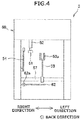
- FIG. 4 is a view of the doffing device 3 when seen from the winding unit 2 side (back side). Accordingly, it should be noted that, the left-right direction in FIG. 4 is opposite of the left-right direction of the automatic winder 1.
- FIG. 5 is a block diagram of an electrical configuration of the automatic winder 1.
- the doffing device 3 moves to a position opposing that winding unit 2 and performs a doffing process for doffing the package P in which the winding has been completed.
- the doffing device 3 can perform other processes such as a yarn-type changing process in which the doffing device 3 collaborates with the winding unit 2 for changing a type of the yarn Y to be wound in the winding section 40, and an upper-yarn cutting process of performing the yarn joining when the yarn Y is discontinued between the package P and the yarn accumulating device 30.
- the doffing device 3 includes a housing 50, a clamp cutter 51, an extendible arm 52, a chucker 53, a cradle opener 54, a yarn shifting lever 62, and the like.
- the housing 50 has an opening in a back surface.
- the housing 50 accommodates various structural components of the doffing device 3.
- the clamp cutter 51 includes a not-shown cutter for cutting the yarn Y and a not-shown clamp for holding the yarn Y.
- the cutter and the clamp of the clamp cutter 51 are driven by an appropriate driving sources such as air cylinders.
- the clamp cutter 51 is attached at a tip end part of the extendible arm 52.
- the extendible arm 52 includes a plurality of rod (tube) members of different diameters and arranged in a coaxially nested manner so as to be extendible and contractible.
- the extendible arm 52 is also configured as an air cylinder, and can be extended or contracted by compressed air supplied from a not-shown compressed air source.
- the extendible arm 52 is pivotable in the front-back direction by a pivot motor 56 (see FIG. 5 ).
- the clamp cutter 51 attached to the tip end part of the extendible arm 52 can move to hold the yarn Y located just below the traversing guide 43, can move the held yarn Y to the side of the winding tube Q, and the like.
- the chucker 53 is attached so as to be rotatable around an axis 57 that extends in the left-right direction in the housing 50.
- the chucker 53 is driven by a chucker driving section 58 (see FIG. 5 ) constituted by a motor and the like so as to rotate up and down around the axis 57.
- the chucker 53 has a chucker part 53a at the tip end part for holding the winding tube Q.
- the chucker 53 takes out one empty winding tube Q from a not-shown stocker located above the automatic winder 1, and after holding the winding tube Q with the chucker part 53a, rotates down and sets the winding tube Q on the cradle 41.
- the cradle opener 54 is attached to a right wall of the housing 50.
- the cradle opener 54 is driven by an opener driving section 59 (see FIG. 5 ) that includes an appropriate driving source such as a cylinder or a motor to perform various operations such as rotation and pivoting to operate a not-shown cradle lever of the cradle 41.
- an appropriate driving source such as a cylinder or a motor to perform various operations such as rotation and pivoting to operate a not-shown cradle lever of the cradle 41.
- the yarn shifting lever 62 is arranged little above the traversing drum 42.
- the yarn shifting lever 62 is rotatable around a support shaft 62a by a yarn shifting motor 63 (see FIG. 5 ).
- the yarn shifting lever 62 can hook the yarn Y with a tip end part thereof and rotate to move the yarn Y.
- the yarn shifting lever 62 is used mainly when fixing the yarn Y to the winding tube Q, and when forming bunch winding.
- the doffing device 3 includes a doffing controlling section 3a constituted by a CPU, a ROM, a RAM, an input-output interface, and the like.
- the doffing controlling section 3a is capable of communicating with the machine-frame controlling device 5.
- the doffing controlling section 3a controls the various driving sections of the doffing device 3 according to a command from the machine-frame controlling device 5.
- FIG. 6 is a flowchart of the doffing process
- FIGS. 7A to 7D are side views schematically showing an operation in the doffing process
- FIGS. 8A to 8C are top views schematically showing an operation in the doffing process.
- the unit controlling section 2a of this winding unit 2 stops the rotation of the traversing drum 42 and the yarn accumulating roller 31 and outputs a signal to the machine-frame controlling device 5 requesting the machine-frame controlling device 5 to instruct to perform the doffing process.
- the doffing device 3 moves to the position of this winding unit 2 in which the winding of the yarn Y has been completed and then starts the doffing process.
- the package P stops rotating as the rotation of the traversing drum 42 has been stopped; however, in this case, as shown in FIG. 7A , the yarn Y is still continuous between the package P and the yarn accumulating device 30.
- the doffing controlling section 3a drives the extendible arm 52 and the pivot motor 56 thereby, as shown in FIG. 7B , moving the clamp cutter 51 to a position where it can hold and cut the yarn Y located just below the traversing guide 43 (Step S101). Then, as shown in FIG. 7C , the yarn Y is cut and a yarn end of the yarn Y from the yarn accumulating device 30 (lower yarn) is held by the clamp cutter 51 (Step S102). The yarn Y from the package P (upper yarn) is wound on the package P.
- Step S103 the doffing controlling section 3a moves the clamp cutter 51, which is holding the yarn Y from the yarn accumulating device 30, to little above a set position (shown with an alternate long and short dash line) of the winding tube Q (Step S103).
- the package P in which the winding has been completed is removed from the cradle 41, and an empty winding tube Q is set on the cradle 41 (Step S104).
- Step S103 and Step S104 it is allowable to appropriately change the contents of Step S103 and Step S104. For example, it is allowable to perform a part of the processing of Step S103 and a part of the processing of Step S104 simultaneously.
- Step S104 is explained in detail below.
- the doffing controlling section 3a drives the opener driving section 59 to cause the cradle opener 54 to operate the not-shown cradle lever.
- the arm 41a and the holder 41b on the right side of the cradle 41 move to the right and open whereby the cradle 41 is released. Accordingly, the package P supported by the cradle 41 can be removed from the cradle 41.
- the doffing controlling section 3a operates the chucker 53 by driving the chucker driving section 58.
- the chucker 53 takes out one empty winding tube Q with the chucker part 53a from the not-shown stocker, and sets the winding tube Q on the cradle 41.
- the "bunch winding” is a yarn layer formed on the winding tube Q outside the traversing area and used in a post-process when unwinding the yarn Y from a plurality of packages P in succession. Specifically, yarn joining is previously performed of a yarn end of a yarn Y in the bunch winding on a package P to be unwound earlier and a winding ending yarn end of an outermost layer on a package P to be unwound later enabling the yarns Y of a plurality of the packages P to be unwound successively.
- Step S105 is explained in more detail below while referring to FIGS. 8A to 8C .
- the doffing controlling section 3a drives the yarn shifting motor 63 whereby, as shown in FIG. 8A , the yarn shifting lever 62 is rotated clockwise in the figure from a standby position (position as shown with an alternate long and short dash line).
- the yarn Y held by the clamp cutter 51 moves to the right side of the winding tube Q and passes through a space between the winding tube Q and the holder 41b on the right side.
- the doffing controlling section 3a returns the yarn shifting lever 62 to the standby position, the unit controlling section 2a causes the traversing drum 42 and the yarn accumulating roller 31 to perform the normal rotation and the winding of the yarn Y is restarted (Step S106).
- the clamp cutter 51 moves to the position where it can hold and cut the yarn Y.
- the clamp cutter 51 is configured so as to be movable with some flexibility by attaching the clamp cutter 51 to the extendible arm 52 that is expandable, contractible, and pivotable, the flexibility in such a movement has been limited to avoid the driving mechanism becoming complicated.
- the clamp cutter 51 when it is difficult to hold the yarn Y that is just below the traversing guide 43, the clamp cutter 51 cannot move to any position other than a predetermined position in the traversing direction of the yarn Y shown with a broken line in FIG. 3 . Therefore, when the yarn Y stops at the position other than the predetermined position in the traversing area, the holding and cutting of the yarn Y cannot be performed with the clamp cutter 51.
- a dedicated positioning member was used for positioning the yarn Y at the position where the clamp cutter 51 can cut and hold the yarn Y.
- Such a positioning member has a width that is slightly wider than the traversing width.
- the yarn Y is traversed while the positioning member is pressed on the yarn Y between the package P and the yarn accumulating device 30, so that the yarn Y is introduced into a notch formed on a surface of the positioning member. That is, the positioning of the yarn Y is performed by introducing the yarn Y into the notch of the positioning member.
- this method requires extra time to move the positioning member to press on the yarn Y and then traverse the yarn Y leading to a degradation in the production efficiency of the package P.
- the rotation of the traversing drum 42 is controlled by controlling the driving source 45, and when the rotation of the traversing drum 42 is stopped, namely when the rotation of the package P is stopped, a yarn stopping control for stopping the yarn Y in the predetermined position in the traversing area is performed.
- a yarn stopping control for stopping the yarn Y in the predetermined position in the traversing area is performed.
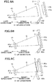
- FIGS. 9A and 9B are views for explaining a first mode of the yarn stopping control.
- FIG. 9A is a flowchart of the yarn stopping control
- FIG. 9B is a graph indicating a variation of the rotational speed of the traversing drum 42 in the yarn stopping control.
- the unit controlling section 2a receives from the yarn detecting sensor 44 a detection signal relating to detection of the yarn Y, and based on this detection signal, controls deceleration and the like of the traversing drum 42 to stop the yarn Y in the predetermined position in the traversing area (Step S202). Thereafter, the rotation of the traversing drum 42 is stopped while controlling the deceleration and the like of the traversing drum 42 (Step S203).
- the yarn Y can be stopped at the predetermined position.
- a process from the starting of the deceleration of the traversing drum 42 up to the stopping of the traversing drum 42 corresponds to a "decelerating step" in the claims
- a process in which the yarn Y that is being traversed during the decelerating step is detected by the yarn detecting sensor 44 corresponds to a "yarn detecting step” in the claims
- a process in which the traversing drum 42 is stopped while controlling the deceleration and the like of the traversing drum 42 corresponds to a "yarn positioning step” in the claims. That is, the yarn positioning step is a part of the decelerating step and it is performed at the end of the decelerating step. Therefore, because it is not necessary to perform the yarn positioning step separately from the decelerating step, the yarn Y can be quickly stopped at the predetermined position.
- FIGS. 10A and 10B are views for explaining a second mode of the yarn stopping control.
- FIG. 10A is a flowchart of the yarn stopping control
- FIG. 10B is a graph indicating a variation of the rotational speed of the traversing drum 42 in the yarn stopping control.
- the unit controlling section 2a receives from the yarn detecting sensor 44 a detection signal relating to detection of the yarn Y; however, the unit controlling section 2a does not immediately perform the control of the deceleration and the like of the traversing drum 42 based on the detection signal, but simply stops the rotation of the traversing drum 42 once (Step S302).
- the unit controlling section 2a after stopping the traversing drum 42 once, based on the detection signal received from the yarn detecting sensor 44 during the deceleration, calculates an amount for which the traversing drum 42 needs to be rotated to stop the yarn Y at the predetermined position, and rotates the traversing drum 42 only for that predetermined amount obtained in the calculation (Step S303). After the traversing drum 42 is rotated for the predetermined amount, the rotation of the traversing drum 42 is stopped (Step S304).
- a process from the starting of the deceleration of the traversing drum 42 up to the stopping of the traversing drum 42 once corresponds to a "decelerating step" in the claims
- a process in which the yarn Y that is being traversed during the decelerating step is detected by the yarn detecting sensor 44 corresponds to a "yarn detecting step” in the claims
- a process in which the traversing drum 42 that is stopped once is rotated for a predetermined amount corresponds to a "yarn positioning step” in the claims. That is, the yarn positioning step is a separate step from the decelerating step, and the yarn positioning step is performed after the decelerating step. In this manner, by performing the yarn positioning step after stopping the traversing drum 42 once, the yarn Y can be stopped at the predetermined position by a relatively simple control than the first mode in which the deceleration is controlled during the decelerating step.
- the traversing drum 42 is controlled by the unit controlling section 2a (controlling section) based on the output of the yarn detecting sensor 44 (yarn detecting section) to perform the yarn stopping control in which the rotation of the package P is stopped so that the yarn Y between the package P and the yarn accumulating device 30 stops at the predetermined position at which the clamp cutter 51 (yarn holding and cutting section) of the doffing device 3 can hold and cut the yarn Y. Therefore, the positioning member needs not be moved as in the conventional technique, so that the clamp cutter 51 can be operated quickly after the package P has stopped. As a result, the time required for the doffing can be shortened so that the production efficiency of the package P can be improved.
- the unit controlling section 2a controls the traversing drum 42 while decelerating the traversing drum 42, and directly stops the rotation of the traversing drum 42 so that the yarn Y between the package P and the yarn accumulating device 30 is stopped at the predetermined position. That is, to stop the yarn Y between the package P and the yarn accumulating device 30 at the predetermined position, the yarn positioning step that stops the rotation of the package P is performed at the end of the decelerating step that decelerates the package P, so that when the decelerating step is completed, the rotation of the package P is stopped in a state in which the yarn Y between the package P and the yarn accumulating device 30 has stopped at the predetermined position. Therefore, the yarn Y between the package P and the yarn accumulating device 30 can be held and cut by moving the clamp cutter 51 relatively quickly so that the time required for the doffing can be further shortened.
- the unit controlling section 2a after stopping the rotation of the traversing drum 42 once, rotates the traversing drum 42 only for the predetermined amount so that the yarn Y between the package P and the yarn accumulating device 30 stops at the predetermined position. That is, the yarn positioning step is performed after the decelerating step, and the traversing drum 42, which was stopped at the decelerating step once, is rotated only for the predetermined amount at the yarn positioning step.
- the yarn Y between the package P and the yarn accumulating device 30 can be stopped at the predetermined position with a relatively simple control.
- the yarn detecting step at which the yarn Y traversed by the traversing drum 42 is detected is performed during the decelerating step. Therefore, it is not necessary to traverse the yarn Y only to perform the yarn detecting step so that the rotation of the package P can be stopped quickly.
- the yarn detecting step can be performed separately from the decelerating step.
- the yarn detecting step can be performed during the yarn positioning step that is performed after stopping the traversing drum 42 once.
- the yarn detecting sensor 44 is arranged in the traversing guide 43; however, the yarn detecting sensor 44 can be arranged at a different position.
- an introducing mechanism 70 for introducing into the clamp cutter 51 the yarn Y present in the traversing area can be integrally formed in the clamp cutter 51.
- the introducing mechanism 70 includes a plate-shaped introducing member 71 and a pair of left and right guiding levers 72.
- the introducing member 71 is substantially trapezoidal in shape.
- a slit-shaped introducing path 71a In a central part in the left-right direction (traversing direction) of the introducing member 71 is formed a slit-shaped introducing path 71a that leads to the clamp cutter 51.
- Each of the guiding levers 72 is pivotable around a support shaft 72a by being driven by a not-shown driving section such as a motor.
- a hooking member 72b for hooking the yarn Y is formed at a tip end part of each of the guiding levers 72 that projects from the introducing member 71.
- the guiding levers 72 are pivotable between an open position shown in FIG.
- FIG. 11A at which the guiding levers 72 are open respectively outside in the traversing direction and a closed position shown in FIG. 11B at which the guiding levers 72 are closed respectively inside in the traversing direction.
- the left and the right guiding levers 72 are located outside of the traversing area of the yarn Y.
- Such an introducing mechanism 70 operates as explained below at Step S101 of the doffing process.
- the clamp cutter 51 is moved downward such that the introducing member 71 is positioned so that a tip end part thereof somewhat presses the yarn Y.
- the guiding levers 72 are assumed to be in the open position.
- the doffing controlling section 3a pivots the guiding levers 72 to the closed position.
- the yarn Y present somewhere in the traversing area is hooked by the hooking member 72b of one of the left and the right guiding levers 72, and the hooked yarn Y is guided directly by the guiding lever 72 into the introducing path 71a.
- the yarn Y is pressed by the tip end part of the introducing member 71, after the yarn Y is guided into the introducing path 71a, the yarn Y moves well inside the introducing path 71a because of the tension on the yarn Y, and the yarn Y is guided to a position where the yarn Y can be held and cut by the clamp cutter 51.
- the yarn Y can be introduced into the clamp cutter 51 by using the introducing mechanism 70 even if the yarn Y between the package P and the yarn accumulating device 30 is anywhere in the traversing area. Therefore, the positioning member needs not be moved as in the conventional technique, so that the clamp cutter 51 can be operated quickly after the package P has stopped. As a result, the time required for the doffing can be shortened so that the production efficiency of the package P can be improved.
- the introducing mechanism 70 includes the introducing member 71 in which is formed the introducing path 71a that introduces the yarn Y into the clamp cutter 51, and the guiding levers 72 that guide the yarn Y present in the traversing area into the introducing path 71a.
- the introducing path 71a is formed in the central part of the introducing member 71 in the traversing direction, and the guiding levers 72 are arranged on either side of the introducing path 71a.
- the specific configuration of the introducing mechanism 70 is not limited to the one shown in FIGS. 11A and 11B .
- the guiding levers can be omitted.
- a central part in the left-right direction (traversing direction) of an introducing member 81 of the introducing mechanism 80 is formed a slit-shaped introducing path 81a that leads to the clamp cutter 51.
- a tip end part of the introducing member 81 are formed into taper parts 81b that protrude respectively toward the tip end part as one goes toward outside in the traversing direction from the introducing path 81a. Because of these taper parts 81b, the yarn Y can be guided into the introducing path 81a by simply moving the introducing member 81 so as to press the yarn Y on the taper part 81b.
- a yarn winding device includes a winding unit that pulls a yarn from a yarn supplying section and winds the yarn on a winding tub in a winding section to form a package; and a doffing device that doffs from the winding unit a package in which the winding has been completed.
- the winding unit includes a traversing drum that rotates while being in contact with the package and traverses the yarn while rotating the package; a yarn accumulating device arranged between the yarn supplying section and the winding section in a yarn travelling direction for temporarily accumulating the yarn; a yarn detecting section capable of detecting the yarn traversed by the traversing drum; and a controlling section that controls the traversing drum.
- the doffing device includes a yarn holding and cutting section capable of holding and cutting the yarn when the yarn between the package and the yarn accumulating device is at a predetermined position in a traversing area.
- the controlling section controls, when the winding of the yarn is completed, a rotation of the traversing drum based on an output of the yarn detecting section such that, when the yarn between the package and the yarn accumulating device is continuous, to stop the rotation of the package so that the yarn between the package and the yarn accumulating device stops at the predetermined position.
Abstract
Description
- The present invention relates to a yarn winding device including a winding unit in which a yarn accumulating device is arranged between a yarn supplying section and a winding section, and a package rotation stopping method implemented in the yarn winding device.
- A yarn winding device including a winding unit that pulls a yarn from a yarn supplying section and winds the yarn on a winding section to form a package is known in the art. In such a yarn winding device, for example, as disclosed in Japanese Patent Application Laid-Open No.
2016-47764 - The clamp cutter of the doffing device is attached to an arm that can be moved by a certain extent by way of expansion, contraction, and pivoting; however, the range in which the clamp cutter can hold or cut the yarn is limited. In a configuration in which the yarn is traversed by a traversing drum on an outer peripheral surface of which a traversing groove has been formed, because where in the traversing groove the yarn is cannot be grasped, a stopping position of the yarn in the traversing area when the traversing drum is stopped varies every time. If the stopping position of the yarn is out of the range in which the clamp cutter can hold and cut the yarn, the doffing cannot be performed.
- Conventionally, a dedicated positioning member that can position the yarn at a position where the clamp cutter can cut and hold the yarn is provided.
- The positioning member has a width that is slightly longer than a traversing width. By traversing the yarn in a state in which the positioning member is pressed on the yarn between the package and the yarn accumulating device, the yarn is introduced into a notch formed on a surface of the positioning member. That is, the positioning of the yarn is performed by introducing the yarn into the notch of the positioning member.
- It is an object of the present invention improve the production efficiency of a package in a yarn winding device including a winding unit in which a yarn accumulating device is arranged between a yarn supplying section and a winding section.
- This object is achieved by the apparatus and method as defined in the independent claims.
- In the above described, conventional positioning method, extra time is required in the doffing to move the positioning member to press on the yarn and then traverse the yarn. Therefore, longer time is required for the doffing, and the production efficiency of the package decreases.
- According to one aspect of the present invention, a yarn winding device includes a winding unit that pulls a yarn from a yarn supplying section and winds the yarn on a winding tub in a winding section to form a package; and a doffing device that doffs from the winding unit a package in which the winding has been completed. The winding unit includes a traversing drum that rotates while being in contact with the package and traverses the yarn while rotating the package; a yarn accumulating device arranged between the yarn supplying section and the winding section in a yarn travelling direction for temporarily accumulating the yarn; a yarn detecting section capable of detecting the yarn traversed by the traversing drum; and a controlling section that controls the traversing drum. The doffing device includes a yarn holding and cutting section capable of holding and cutting the yarn when the yarn between the package and the yarn accumulating device is at a predetermined position in a traversing area. The controlling section controls, when the winding of the yarn is completed, a rotation of the traversing drum based on an output of the yarn detecting section such that, when the yarn between the package and the yarn accumulating device is continuous, to stop the rotation of the package so that the yarn between the package and the yarn accumulating device stops at the predetermined position.
- According to another aspect of the present invention, a package rotation stopping method for stopping rotation of a package is implemented in a yarn winding device. The yarn winding device includes a winding unit that, after temporarily accumulating a yarn pulled from a yarn supplying section in a yarn accumulating device, forms a package by winding the yarn on a winding tube while traversing the yarn with a traversing drum that rotates while being in contact with the package; and a doffing device that doffs from the winding unit a package in which the winding has been completed and including a yarn holding and cutting section capable of holding and cutting the yarn when the yarn between the package and the yarn accumulating device is at a predetermined position in a traversing area. The package rotation stopping method includes a decelerating step of decelerating, when the winding of the yarn is completed, the traversing drum while the yarn between the package and the yarn accumulating device is continuous thereby decelerating the package; a yarn detecting step of detecting the yarn traversed by the traversing drum; and a yarn positioning step of controlling the traversing drum based on a detection result of the yarn obtained at the yarn detecting step to stop the rotation of the package so that the yarn between the package and the yarn accumulating device stops at the predetermined position.
- According to still another aspect of the present invention, a yarn winding device includes a winding unit that pulls a yarn from a yarn supplying section and winds the yarn on a winding tube in a winding section to form a package; and a doffing device that doffs from the winding unit a package in which the winding has been completed. The winding unit includes a traversing drum that rotates while being in contact with the package and traverses the yarn while rotating the package; and a yarn accumulating device arranged between the yarn supplying section and the winding section in a yarn travelling direction for temporarily accumulating the yarn. The winding unit, when the winding of the yarn is completed, stops the rotation of the package while the yarn between the package and the yarn accumulating device is continuous. The doffing device includes a yarn holding and cutting section capable of holding and cutting the yarn between the package and the yarn accumulating device; and an introducing mechanism arranged integrally with the yarn holding and cutting section and that introduces into the yarn holding and cutting section the yarn present in a traversing area between the package and the yarn accumulating device.
- In the above yarn winding device, when the winding of the yarn is completed, the traversing drum is controlled based on the output of the yarn detecting section to stop the rotation of the package so that the yarn between the package and the yarn accumulating device stops at the predetermined position at which the yarn holding and cutting section of the doffing device can hold and cut the yarn. Therefore, the positioning member needs not be moved as in the conventional technique, so that the yarn holding and cutting section can be operated quickly after the package has stopped. As a result, the time required for the doffing can be shortened so that the production efficiency of the package can be improved.
- In the above yarn winding device, it is preferable that the controlling section controls the traversing drum while decelerating the traversing drum, and directly stops the rotation of the traversing drum so that the yarn between the package and the yarn accumulating device stops at the predetermined position.
- In such a control, when the rotation of the package in which the winding has been completed is decelerated and finally stopped, the yarn between the package and the yarn accumulating device stops at the predetermined position. Therefore, the yarn between the package and the yarn accumulating device can be held and cut by moving the yarn holding and cutting section relatively quickly so that the time required for the doffing can be further shortened.
- In the above yarn winding device, the controlling section, after stopping the rotation of the traversing drum once, can rotate the traversing drum for a predetermined amount so that the yarn between the package and the yarn accumulating device stops at the predetermined position.
- By rotating the traversing drum only for the predetermined amount from the stopped state thereof, when stopping the yarn between the package and the yarn accumulating device at the predetermined position, the control of the traversing drum can be avoided from becoming complicated and the yarn can be stopped precisely at the predetermined position.
- In the above yarn winding device, it is preferable that the yarn winding device further includes a guiding member arranged upstream of the traversing drum but downstream of the yarn accumulating device in the yarn travelling direction for enclosing the yarn traversed by the traversing drum, and the yarn detecting section is arranged in the guiding member.
- In such a configuration, the yarn detecting section can be arranged near the yarn without interfering with the yarn.
- According to another aspect of the present invention, a package rotation stopping method for stopping rotation of a package is implemented in a yarn winding device. The yarn winding device includes a winding unit that, after temporarily accumulating a yarn pulled from a yarn supplying section in a yarn accumulating device, forms a package by winding the yarn on a winding tube while traversing the yarn with a traversing drum that rotates while being in contact with the package; and a doffing device that doffs from the winding unit a package in which the winding has been completed and including a yarn holding and cutting section capable of holding and cutting the yarn when the yarn between the package and the yarn accumulating device is at a predetermined position in a traversing area. The package rotation stopping method includes a decelerating step of decelerating, when the winding of the yarn is completed, the traversing drum while the yarn between the package and the yarn accumulating device is continuous thereby decelerating the package; a yarn detecting step of detecting the yarn traversed by the traversing drum; and a yarn positioning step of controlling the traversing drum based on a detection result of the yarn obtained at the yarn detecting step to stop the rotation of the package so that the yarn between the package and the yarn accumulating device stops at the predetermined position.
- In the above package rotation stopping method, when the winding of the yarn is completed, the traversing drum is controlled based on the detection result of the yarn obtained at the yarn detecting step to stop the rotation of the package so that the yarn between the package and the yarn accumulating device stops at the predetermined position at which the yarn holding and cutting section of the doffing device can hold and cut the yarn. Therefore, the positioning member needs not be moved as in the conventional technique, so that the yarn holding and cutting section can be operated quickly after the package has stopped. As a result, the time required for the doffing can be shortened so that the production efficiency of the package can be improved.
- In the above package rotation stopping method, it is preferable that the yarn detecting step is performed during the decelerating step.
- By performing the yarn detecting step during the decelerating step, it is not necessary to traverse the yarn only to perform the yarn detecting step so that the rotation of the package can be stopped quickly.
- In the above package rotation stopping method, it is preferable that the yarn positioning step is performed at the end of the decelerating step so that when the decelerating step is completed, the rotation of the package is stopped in a state in which the yarn between the package and the yarn accumulating device is at the predetermined position.
- In such a control, when the rotation of the package in which the winding has been completed is decelerated and finally stopped, the yarn between the package and the yarn accumulating device stops at the predetermined position. Therefore, the yarn between the package and the yarn accumulating device can be held and cut by moving the yarn holding and cutting section relatively quickly so that the time required for the doffing can be further shortened.
- In the above package rotation stopping method, it is preferable that the yarn positioning step is performed after the decelerating step, and the traversing drum that was stopped once at the decelerating step is rotated only for a predetermined amount at the yarn positioning step.
- By rotating the traversing drum only for the predetermined amount from the stopped state thereof, the yarn between the package and the yarn accumulating device can be stopped at the predetermined position with a relatively simple control.
- According to still another aspect of the present invention, a yarn winding device includes a winding unit that pulls a yarn from a yarn supplying section and winds the yarn on a winding tube in a winding section to form a package; and a doffing device that doffs from the winding unit a package in which the winding has been completed. The winding unit includes a traversing drum that rotates while being in contact with the package and traverses the yarn while rotating the package; and a yarn accumulating device arranged between the yarn supplying section and the winding section in a yarn travelling direction for temporarily accumulating the yarn. The winding unit, when the winding of the yarn is completed, stops the rotation of the package while the yarn between the package and the yarn accumulating device is continuous. The doffing device includes a yarn holding and cutting section capable of holding and cutting the yarn between the package and the yarn accumulating device; and an introducing mechanism arranged integrally with the yarn holding and cutting section and that introduces into the yarn holding and cutting section the yarn present in a traversing area between the package and the yarn accumulating device.
- In the above yarn winding device, the introducing mechanism that introduces into the yarn holding and cutting section the yarn present in the traversing area between the package and the yarn accumulating device is arranged integrally with the yarn holding and cutting section. Accordingly, when stopping the rotation of the package in which the winding has been completed, the yarn can be introduced into the yarn holding and cutting section by using the introducing mechanism even if the yarn between the package and the yarn accumulating device is anywhere in the traversing area. Therefore, the positioning member needs not be moved as in the conventional technique, so that the yarn holding and cutting section can be operated quickly after the package has stopped. As a result, the time required for the doffing can be shortened so that the production efficiency of the package can be improved.
- In the above yarn winding device, it is preferable that the introducing mechanism includes an introducing member in which is formed an introducing path for introducing the yarn into the yarn holding and cutting section; and a guiding lever that guides into the introducing path the yarn present in the traversing area.
- By introducing the yarn into the introducing path by using the guiding lever, the yarn between the package and the yarn accumulating device can be surely introduced into the yarn holding and cutting section.
- In the above yarn winding device, it is preferable that the introducing path is formed in a central part of the introducing member in a traversing direction, and the guiding lever is arranged on either side of the introducing path.
- By arranging the guiding lever on either side of the introducing path, the yarn between the package and the yarn accumulating device can be more surely introduced into the yarn holding and cutting section.
- In the above explanation, the meaning of "a plurality of" also includes "a predetermined number of".
- Although the invention has been explained with respect to specific embodiments for a complete and clear disclosure, the appended claims are not to be thus limited but are to be construed as embodying all modifications and alternative constructions that may occur to one skilled in the art that fairly fall within the scope of the claims.
- The above and other objects, features, advantages and technical and industrial significance of this invention will be better understood by reading the following detailed description of presently preferred embodiments of the invention, when considered in connection with the accompanying drawings.
-
-
FIG. 1 is a front view of an automatic winder according to one embodiment of the present invention. -
FIG. 2 is a side view of a winding unit. -
FIG. 3 is a front view of a winding section of the winding unit. -
FIG. 4 is a view of a doffing device when seen from the winding unit side. -
FIG. 5 is a block diagram of an electrical configuration of the automatic winder. -
FIG. 6 is a flowchart of a doffing process. -
FIGS. 7A to 7D are side views schematically showing an operation in the doffing process. -
FIGS. 8A to 8C are top views schematically showing an operation in the doffing process. -
FIGS. 9A and 9B are views for explaining a first mode of a yarn stopping control. -
FIGS. 10A and 10B are views for explaining a second mode of the yarn stopping control. -
FIGS. 11A and 11B are schematic diagrams of a configuration of an introducing mechanism. -
FIG. 12 is a schematic diagram of a variation of the introducing mechanism. - Exemplary embodiments of the present invention are explained in detail with reference to the accompanying drawings.
-
FIG. 1 is a front view of an automatic winder according to one embodiment of the present invention. As shown inFIG. 1 , an automatic winder 1 (yarn winding device of the present invention) includes a plurality of windingunits 2 arranged along a predetermined arrangement direction (left-right direction inFIG. 1 ), adoffing device 3 capable of traveling along the arrangement direction, a bobbin supplying device 4 that supplies a yarn supplying bobbin B, and a machine-frame controlling device 5. Note that, in the automatic winder 1 according to the present embodiment, a left-right direction inFIG. 1 is termed as "left-right direction", an up-down direction inFIG. 1 is termed as "up-down direction", a front side in a direction orthogonal to the paper surface ofFIG. 1 is termed as "front direction", and a back side in the direction orthogonal to the paper surface ofFIG. 1 is termed as "back direction". - The winding
unit 2 unwinds a yarn Y from a yarn supplying bobbin B and winds the yarn Y on a winding tube Q (seeFIG. 2 ) to form a package P. When the winding of the yarn Y is completed in a certain windingunit 2, thedoffing device 3 travels along the arrangement direction to the position of that windingunit 2. Then, thedoffing device 3 doffs the package P, in which the winding of the yarn Y has been completed, from this windingunit 2, and sets an empty winding tube Q in its place. The bobbin supplying device 4 mounts a yarn supplying bobbin B on a conveying tray T and supplies the yarn supplying bobbin B supported by the conveying tray T to a desired one of the windingunits 2. The machine-frame controlling device 5 controls an operation of each of the windingunits 2, thedoffing device 3, and the bobbin supplying device 4. An operator can centrally manage the windingunits 2 by appropriately operating the machine-frame controlling device 5. -
FIG. 2 is a side view of the windingunit 2. As shown inFIG. 2 , the windingunit 2 includes ayarn supplying section 10 that supplies the yarn Y while unwinding the yarn Y wound on the yarn supplying bobbin B, ayarn processing section 20 that performs various processes on the yarn Y supplied from theyarn supplying section 10, ayarn accumulating device 30 that temporarily accumulates the yarn Y that has passed theyarn processing section 20, and a windingsection 40 that winds the yarn Y on the winding tube Q while traversing the yarn Y from theyarn accumulating device 30 to form a package P. Theyarn supplying section 10, theyarn processing section 20, theyarn accumulating device 30, and the windingsection 40 are arranged in this order from bottom to top. In the following explanation, upstream and downstream in a yarn travelling direction, which is a direction in which the yarn travels from theyarn supplying section 10 to the windingsection 40 after passing through theyarn processing section 20 and theyarn accumulating device 30, are simply called upstream and downstream, respectively. - The
yarn supplying section 10 includes a yarnunwinding assisting device 11 that assists the unwinding of the yarn Y when unwinding the yarn Y from the yarn supplying bobbin B held in an upright state by the conveying tray T. The yarnunwinding assisting device 11 controls a size of a balloon of the yarn Y unwound from the yarn supplying bobbin B to an appropriate size by using a regulatingpipe 12 thereby preventing excessive increase of a tension of the yarn Y unwound from the yarn supplying bobbin B. When the entire yarn Y is unwound from the yarn supplying bobbin B, theyarn supplying section 10 discharges the empty yarn supplying bobbin B and receives a new yarn supplying bobbin B from the bobbin supplying device 4. - The
yarn processing section 20 includes an upperyarn catching member 21, ayarn joining device 22, a loweryarn catching member 23, atension applying device 24, ayarn monitoring device 25, and the like. The upperyarn catching member 21, theyarn joining device 22, the loweryarn catching member 23, thetension applying device 24, and theyarn monitoring device 25 are arranged in this order from upstream to downstream. - The upper
yarn catching member 21 is arranged near but upstream of theyarn joining device 22. The upperyarn catching member 21 is connected to a not-shown negative pressure source. When performing the yarn joining, the upperyarn catching member 21 can generate a suction airflow and suck and catch the yarn Y from the windingsection 40. The upperyarn catching member 21 guides the caught yarn Y to theyarn joining device 22. - The
yarn joining device 22 performs the yarn joining of a discontinuous yarn Y. When the yarn Y between theyarn supplying section 10 and the windingsection 40 becomes discontinuous, for example, when the yarn Y is cut with acutter 25b when amonitoring section 25a of theyarn monitoring device 25 detects a yarn defect, when a yarn breakage occurs in which the yarn Y is discontinued between the yarn supplying bobbin B and the package P, when replacing the yarn supplying bobbin B, and the like, theyarn joining device 22 performs yarn joining of a yarn Y from the yarn supplying section 10 (lower yarn) and a yarn Y from the winding section 40 (upper yarn). Theyarn joining device 22 is arranged at a position that is slightly retracted from a yarn path. Theyarn joining device 22 joins yarn ends introduced thereinto by the upperyarn catching member 21 and the loweryarn catching member 23 so that the yarn Y becomes continuous. As theyarn joining device 22, a device that uses fluid such as compressed air, or a mechanical device can be used. - The lower
yarn catching member 23 is arranged near but downstream of theyarn joining device 22. The loweryarn catching member 23 is connected to a not-shown negative pressure source. The loweryarn catching member 23 is a cylindrical member with an opening formed in a tip end part thereof. The loweryarn catching member 23 includes adriving section 23a. Thedriving section 23a drives the loweryarn catching member 23 so as to advance to and retreat from the yarn path. - The lower
yarn catching member 23 generates a suction airflow at the tip thereof when the tip is near the yarn path. Accordingly, a yarn end of the yarn Y from the yarn supplying bobbin B that is blown by a later-explained lower yarn blow-feedingmember 26 is sucked and caught by the loweryarn catching member 23. The loweryarn catching member 23 can be configured to generate a suction airflow at the tip thereof to suck and remove fly-waste and the like that may be attached to the travelling yarn Y. The loweryarn catching member 23 introduces the yarn end into theyarn joining device 22 after moving away from the yarn path in a state in which it has caught the yarn end from the yarn supplying bobbin B. - The
tension applying device 24 applies a predetermined tension to the traveling yarn Y. Thetension applying device 24 is a gate-type member having fixed comb teeth and movable comb teeth, and applies a predetermined resistance on the yarn Y when the yarn Y travels between the comb teeth. The movable comb teeth can be moved by, for example, a solenoid, to change a distance between the movable comb teeth and the fixed comb teeth. As a result, thetension applying device 24 can adjust the tension applied to the yarn Y. Note that, the configuration of thetension applying device 24 is not limited to the gate-type, and it can be a disk-type tension applying device, for example. - The
yarn monitoring device 25 includes themonitoring section 25a that detects a yarn defect such as slub or mixing of a foreign substance by monitoring a thickness and the like of the yarn Y with an appropriate sensor. Moreover, in theyarn monitoring device 25, thecutter 25b is arranged upstream of themonitoring section 25a. Thecutter 25b cuts the yarn Y immediately when themonitoring section 25a detects a yarn defect. - To surely perform the yarn joining, the
yarn processing section 20 includes the lower yarn blow-feedingmember 26, an upper yarn blow-feedingmember 27, and ayarn guiding member 28. - The lower yarn blow-feeding
member 26 is a cylindrical member arranged near but downstream of the yarnunwinding assisting device 11. By jetting compressed air, the lower yarn blow-feedingmember 26 generates an air current that can blow and feed the yarn Y to the loweryarn catching member 23. Accordingly, when a yarn breakage has occurred or after the yarn supplying bobbin B has been replaced, the lower yarn blow-feedingmember 26 operates whereby the yarn end from the yarn supplying bobbin B can be caught with the loweryarn catching member 23 and this yarn end can be introduced into theyarn joining device 22. - Note that, if it is just after a new yarn supplying bobbin B has been supplied to the
yarn supplying section 10, because enough yarn Y has not been pulled from the yarn supplying bobbin B, it may be difficult for the lower yarn blow-feedingmember 26 to blow and feed the yarn end to theyarn joining device 22. To handle such a situation, an auxiliary blow-feeding member 13 is arranged in theyarn supplying section 10. The auxiliary blow-feeding member 13 is positioned right below the conveying tray T that is arranged in theyarn supplying section 10. The auxiliary blow-feeding member 13 jets compressed air inside the conveying tray T and the yarn supplying bobbin B both of which are hollow inside. As a result, an air current that blows and feeds the yarn Y from the yarn supplying bobbin B to the lower yarn blow-feedingmember 26 is generated at a tip end part of the yarn supplying bobbin B. In this manner, the auxiliary blow-feeding member 13 and the lower yarn blow-feedingmember 26 operate together when the new yarn supplying bobbin B is supplied. As a result, the yarn end from the yarn supplying bobbin B can be surely fed to theyarn joining device 22. - The upper yarn blow-feeding
member 27 is a cylindrical member arranged near but upstream of theyarn accumulating device 30. By jetting compressed air, the upper yarn blow-feedingmember 27 generates an air current that can blow and feed a yarn end from theyarn accumulating device 30 to the upperyarn catching member 21. - The
yarn guiding member 28 is a cylindrical member that is curved and projects toward the front direction so as to detour around theyarn monitoring device 25, thetension applying device 24, theyarn joining device 22, and the like. An opening is formed at each of the longitudinal ends of theyarn guiding member 28. The opening on one end opposes an outlet of the upper yarn blow-feedingmember 27, and the opening on the other end opposes the upperyarn catching member 21. A not-shown slit is formed in a back side of theyarn guiding member 28 over an entire length of theyarn guiding member 28 so that the yarn Y that passes inside theyarn guiding member 28 from the opening on one end to the opening on the other end can be taken out of theyarn guiding member 28. - The upper yarn blow-feeding
member 27 catches the yarn end from theyarn accumulating device 30 and blows the same to the inside of theyarn guiding member 28, pulls the yarn Y along theyarn guiding member 28, and causes the yarn Y to be caught by the upperyarn catching member 21. In this manner, the yarn Y from theyarn accumulating device 30 is blown and fed by the upper yarn blow-feedingmember 27 and guided to theyarn joining device 22. - The
yarn accumulating device 30 is arranged between theyarn processing section 20 and the windingsection 40 in the yarn travelling direction. Theyarn accumulating device 30 pulls the yarn Y from theyarn supplying section 10, temporarily accumulates the pulled yarn Y and supplies the yarn Y to the windingsection 40. Because of theyarn accumulating device 30, it is prevented that the variations in the tension of the yarn Y unwound from the yarn supplying bobbin B are transmitted to the windingsection 40 side. As a result, the variations in the tension of the yarn Y supplied to the windingsection 40 can be suppressed leading to formation of a good quality package P. Moreover, because of theyarn accumulating device 30, the winding of the yarn Y by the windingsection 40 can be continued even while performing the yarn joining. - The
yarn accumulating device 30 includes ayarn accumulating roller 31 on which the yarn Y can be wound, and aroller driving motor 32 that rotationally drives theyarn accumulating roller 31. Theroller driving motor 32 can rotate theyarn accumulating roller 31 in a winding direction of the yarn Y from the yarn supplying section 10 (normal rotation) and can rotate theyarn accumulating roller 31 in an opposite direction of the winding direction (reverse rotation). The yarn Y wound on theyarn accumulating roller 31 is pulled to the downstream via a pullingguide 35 arranged on a line that extends from a central axis of theyarn accumulating roller 31. - The
yarn accumulating roller 31 has a cylindrical shape and it is formed, for example, of metal. When theyarn accumulating roller 31 performs the normal rotation while the yarn Y has been wound thereon, the tension is applied to the yarn Y on the upstream side of theyarn accumulating device 30. As a result, the yarn Y is unwound from the yarn supplying bobbin B and the yarn Y is wound around an outer peripheral surface 31a of theyarn accumulating roller 31 thereby accumulating the yarn Y. In the below explanation, an end of theyarn accumulating roller 31 near theroller driving motor 32 will be called a base end and the opposite end will be called a tip end. - A
ring member 33 is arranged on the outer peripheral surface 31a of theyarn accumulating roller 31 on a tip of the tip end thereof. Thering member 33 has a circular shape and it is formed, for example, of rubber. Thering member 33 is fit on the outer peripheral surface 31a by an elastic force that acts inward in a radial direction of thering member 33. The yarn Y is passed inside thering member 33. Accordingly, a resistance is applied on the yarn Y pulled from theyarn accumulating roller 31 because of the elastic force of thering member 33. Accordingly, an appropriate tension is applied to the yarn Y that is being pulled from theyarn accumulating roller 31 allowing the unwinding of the yarn Y from theyarn accumulating roller 31 to be performed in a stable manner. - A groove 31b is formed in the outer peripheral surface 31a of the
yarn accumulating roller 31 along an axial direction of theyarn accumulating roller 31 below the location of thering member 33 as well. An urgingmember 36 that is biased outward in the radial direction by a not-shown spring is accommodated in a portion of the groove 31b that intersects with thering member 33. This urgingmember 36 is forcefully pushed inward in the radial direction by a later-explainedyarn passing nozzle 34. When the urgingmember 36 is pushed inward in the radial direction, a gap is produced between thering member 33 and the urgingmember 36 and the yarn Y can be passed through this gap. - The
yarn accumulating device 30 includes the cylindricalyarn passing nozzle 34. Theyarn passing nozzle 34 is arranged near theyarn accumulating roller 31. One end of theyarn passing nozzle 34 is arranged so as to oppose the outer peripheral surface 31a of theyarn accumulating roller 31 on the tip of the tip end thereof. Theyarn passing nozzle 34 is configured so that the compressed air can be passed inside thereof from the other end to the one end. That is, the other end (the end that is on an opposite side of a side on which theyarn accumulating roller 31 is present) of theyarn passing nozzle 34 functions as a suction port that sucks the yarn Y, and the one end (the end that opposes the yarn accumulating roller 31) of theyarn passing nozzle 34 functions as a blowing port for blowing off the sucked yarn Y. Theyarn passing nozzle 34 can be moved toward or away from the outer peripheral surface 31a of theyarn accumulating roller 31 by, for example, a sliding mechanism that uses an actuator such as an air cylinder or a motor. - When the
yarn passing nozzle 34 is moved toward the outer peripheral surface 31a of theyarn accumulating roller 31 while the urgingmember 36 is opposing the one end of theyarn passing nozzle 34, theyarn passing nozzle 34 forcefully pushes the urgingmember 36 inward in the radial direction against the urging force of the spring, and a gap is formed between thering member 33 and the urgingmember 36. In this state, when the yarn Y is brought near the other end (suction port) of theyarn passing nozzle 34 and the compressed air is flown from the other end to the one end of theyarn passing nozzle 34, the yarn Y can be passed through this gap and the yarn Y can be blown off from the tip end (windingsection 40 side) to the base end (yarn supplying section 10 side) inside the groove 31b. In this manner, the yarn Y can be passed to theyarn accumulating roller 31. A not-shown slit is formed in theyarn passing nozzle 34 along a length direction thereof so that the yarn Y that is passed to theyarn accumulating roller 31 can be taken out from theyarn passing nozzle 34. - The yarn end of the yarn Y that has passed from the tip end side to the base end side of the
yarn accumulating roller 31 is further blown by the upper yarn blow-feedingmember 27 to theyarn guiding member 28, caught by the upperyarn catching member 21, and guided to theyarn joining device 22. -
FIG. 3 is a front view of the windingsection 40 of the windingunit 2. The windingsection 40 includes acradle 41 on which the winding tube Q can be mounted, a traversingdrum 42 that rotates the winding tube Q or the package P while traversing the yarn Y, and a traversingguide 43 that guides the yarn Y traversed by the traversingdrum 42. - The
cradle 41 includes a pair of left andright arms 41a and a pair of left andright holders 41b attached respectively in the inside of each of thearms 41a. Accordingly, thecradle 41 can rotatably support the winding tube Q or the package P with theholders 41b. Thecradle 41 can cause an outer peripheral surface of the supported package P to contact an outer peripheral surface of the traversingdrum 42. - The traversing
drum 42 is rotationally driven by a drivingsource 45 constituted by a motor and the like. The winding tube Q or the package P is rotatably driven when the traversingdrum 42 that is in contact with the outer peripheral surface of the winding tube Q or the package P is rotated. The traversingdrum 42 can pull the yarn Y from theyarn accumulating device 30 and rotate in a winding direction (normal rotation) for winding the yarn Y on the winding tube Q, or can rotate to pull the yarn Y from the package P (reverse rotation). A traversinggroove 42a is formed in the outer peripheral surface of the traversingdrum 42. The traversingdrum 42 can traverse the yarn Y in a traversing area by using this traversinggroove 42a. In this manner, the package P of a predetermined shape can be formed while winding the yarn Y on the winding tube Q while traversing the yarn Y with the traversingdrum 42. Note that, left and right end positions of the yarn Y (both end positions of the traversing area) during the traversing are only schematically shown inFIG. 3 . - The traversing
guide 43 is arranged near but upstream of the traversingdrum 42 and relatively in the front direction of the traversingdrum 42. The traversingguide 43 is a plate member formed of metal and the like. The traversingguide 43 includes afirst guide wall 43a, left and rightsecond guide walls 43b, and left and rightyarn introducing members 43c. - A shape of the
first guide wall 43a when seen from the front direction is substantially trapezoidal, and a surface thereof on a front side (a side that is opposite of the side on which the traversingdrum 42 is present) functions as a guiding surface. The yarn Y that is traversed by the traversingdrum 42 is guided while being in contact with the guiding surface of thefirst guide wall 43a, and the yarn Y performs reciprocating movement along an axial direction (traversing direction) of the traversingdrum 42. - Each of the
second guide walls 43b is connected to each of edges of thefirst guide wall 43a in the traversing direction. Thesecond guide walls 43b are folded back toward the front side with respect to thefirst guide wall 43a and each of thesecond guide walls 43b encloses a respective edge of thefirst guide wall 43a in the traversing direction. Floating up of the yarn Y on the front side guided by thefirst guide wall 43a is prevented by thesecond guide walls 43b. - Each of the
yarn introducing members 43c is connected to each of top edges of thesecond guide walls 43b. Theyarn introducing members 43c are bent gently toward the front side with respect to thesecond guide walls 43b. Theyarn introducing members 43c overlap with each other in a front-back direction such that an inner edge in the traversing direction of oneyarn introducing member 43c extends in the front side than an inner edge in the traversing direction of the otheryarn introducing member 43c, and agap 43d for passing the yarn Y is formed in a region where theyarn introducing members 43c overlap in the front-back direction. The yarn Y positioned on the front side of thesecond guide walls 43b and theyarn introducing members 43c moves to a position where it contacts thefirst guide wall 43a after passing through thegap 43d by the yarn Y being traversed by the rotation of the traversingdrum 42. - A
yarn detecting sensor 44 is arranged on a left edge of thefirst guide wall 43a. Theyarn detecting sensor 44 is an optical sensor of a so-called reflection type in which a light emitting element and a light receiving element are arranged adjacent to each other. A through-hole 43e is formed in a leftsecond guide wall 43b at a position opposing theyarn detecting sensor 44. As a result, when the yarn Y is at a position opposing theyarn detecting sensor 44, light emitted from the light emitting element of theyarn detecting sensor 44 is reflected by the yarn Y, and the reflected light is received in the light receiving element. In contrast, when the yarn Y is at a position where it does not oppose theyarn detecting sensor 44, the light emitted from the light emitting element of theyarn detecting sensor 44 is not reflected by the yarn Y, and no reflected light is received in the light receiving element as the emitted light passes through the through-hole 43e. Whether the traversing is being performed normally can be determined based on whether the reflected light is received in the light receiving element of theyarn detecting sensor 44 in a predetermined traversing cycle. - Each of the winding
units 2 includes aunit controlling section 2a (seeFIG. 5 ) constituted by a CPU, a ROM, a RAM, an input-output interface, and the like. Theunit controlling section 2a controls operations of various structural components such as theyarn supplying section 10, theyarn processing section 20, theyarn accumulating device 30, and the windingsection 40. Moreover, each of theunit controlling sections 2a is capable of communicating with the machine-frame controlling device 5 so that operations of a plurality of the windingunits 2 are centrally managed by the machine-frame controlling device 5. - The
doffing device 3 is explained below.FIG. 4 is a view of thedoffing device 3 when seen from the windingunit 2 side (back side). Accordingly, it should be noted that, the left-right direction inFIG. 4 is opposite of the left-right direction of the automatic winder 1.FIG. 5 is a block diagram of an electrical configuration of the automatic winder 1. - When the winding of the yarn Y in a certain winding
unit 2 is completed, thedoffing device 3 moves to a position opposing that windingunit 2 and performs a doffing process for doffing the package P in which the winding has been completed. Apart from the doffing process, thedoffing device 3 can perform other processes such as a yarn-type changing process in which thedoffing device 3 collaborates with the windingunit 2 for changing a type of the yarn Y to be wound in the windingsection 40, and an upper-yarn cutting process of performing the yarn joining when the yarn Y is discontinued between the package P and theyarn accumulating device 30. - The
doffing device 3 includes ahousing 50, aclamp cutter 51, anextendible arm 52, achucker 53, acradle opener 54, ayarn shifting lever 62, and the like. Thehousing 50 has an opening in a back surface. Thehousing 50 accommodates various structural components of thedoffing device 3. - The
clamp cutter 51 includes a not-shown cutter for cutting the yarn Y and a not-shown clamp for holding the yarn Y. The cutter and the clamp of theclamp cutter 51 are driven by an appropriate driving sources such as air cylinders. Theclamp cutter 51 is attached at a tip end part of theextendible arm 52. Theextendible arm 52 includes a plurality of rod (tube) members of different diameters and arranged in a coaxially nested manner so as to be extendible and contractible. Moreover, theextendible arm 52 is also configured as an air cylinder, and can be extended or contracted by compressed air supplied from a not-shown compressed air source. Moreover, theextendible arm 52 is pivotable in the front-back direction by a pivot motor 56 (seeFIG. 5 ). In this manner, because theextendible arm 52 is extendible, contractible, and pivotable, theclamp cutter 51 attached to the tip end part of theextendible arm 52 can move to hold the yarn Y located just below the traversingguide 43, can move the held yarn Y to the side of the winding tube Q, and the like. - The
chucker 53 is attached so as to be rotatable around anaxis 57 that extends in the left-right direction in thehousing 50. Thechucker 53 is driven by a chucker driving section 58 (seeFIG. 5 ) constituted by a motor and the like so as to rotate up and down around theaxis 57. Thechucker 53 has a chucker part 53a at the tip end part for holding the winding tube Q. Thechucker 53 takes out one empty winding tube Q from a not-shown stocker located above the automatic winder 1, and after holding the winding tube Q with the chucker part 53a, rotates down and sets the winding tube Q on thecradle 41. - The
cradle opener 54 is attached to a right wall of thehousing 50. Thecradle opener 54 is driven by an opener driving section 59 (seeFIG. 5 ) that includes an appropriate driving source such as a cylinder or a motor to perform various operations such as rotation and pivoting to operate a not-shown cradle lever of thecradle 41. When the cradle lever is operated, as shown inFIGS. 8A to 8C , thearm 41a and theholder 41b on the right side of thecradle 41 are opened and closed enabling removing of the package P in which the winding has been completed, and mounting of an empty winding tube Q on thecradle 41. - The
yarn shifting lever 62 is arranged little above the traversingdrum 42. Theyarn shifting lever 62 is rotatable around asupport shaft 62a by a yarn shifting motor 63 (seeFIG. 5 ). Theyarn shifting lever 62 can hook the yarn Y with a tip end part thereof and rotate to move the yarn Y. Theyarn shifting lever 62 is used mainly when fixing the yarn Y to the winding tube Q, and when forming bunch winding. - As shown in
FIG. 5 , thedoffing device 3 includes adoffing controlling section 3a constituted by a CPU, a ROM, a RAM, an input-output interface, and the like. Thedoffing controlling section 3a is capable of communicating with the machine-frame controlling device 5. Thedoffing controlling section 3a controls the various driving sections of thedoffing device 3 according to a command from the machine-frame controlling device 5. - In the automatic winder 1 having the above explained configuration, the doffing process of doffing the package P in which the winding has been completed is automatically performed by the winding
unit 2 and thedoffing device 3 collaborating with each other.FIG. 6 is a flowchart of the doffing process,FIGS. 7A to 7D are side views schematically showing an operation in the doffing process, andFIGS. 8A to 8C are top views schematically showing an operation in the doffing process. - When the yarn Y of a predetermined amount is wound in a certain winding
unit 2 whereby it is detected that the winding of the yarn Y has completed, theunit controlling section 2a of this windingunit 2 stops the rotation of the traversingdrum 42 and theyarn accumulating roller 31 and outputs a signal to the machine-frame controlling device 5 requesting the machine-frame controlling device 5 to instruct to perform the doffing process. In response to this instruction from the machine-frame controlling device 5, thedoffing device 3 moves to the position of this windingunit 2 in which the winding of the yarn Y has been completed and then starts the doffing process. Note that, the package P stops rotating as the rotation of the traversingdrum 42 has been stopped; however, in this case, as shown inFIG. 7A , the yarn Y is still continuous between the package P and theyarn accumulating device 30. - At first, the
doffing controlling section 3a drives theextendible arm 52 and thepivot motor 56 thereby, as shown inFIG. 7B , moving theclamp cutter 51 to a position where it can hold and cut the yarn Y located just below the traversing guide 43 (Step S101). Then, as shown inFIG. 7C , the yarn Y is cut and a yarn end of the yarn Y from the yarn accumulating device 30 (lower yarn) is held by the clamp cutter 51 (Step S102). The yarn Y from the package P (upper yarn) is wound on the package P. - Subsequently, as shown in
FIG. 7D , thedoffing controlling section 3a moves theclamp cutter 51, which is holding the yarn Y from theyarn accumulating device 30, to little above a set position (shown with an alternate long and short dash line) of the winding tube Q (Step S103). The package P in which the winding has been completed is removed from thecradle 41, and an empty winding tube Q is set on the cradle 41 (Step S104). Note that, it is allowable to appropriately change the contents of Step S103 and Step S104. For example, it is allowable to perform a part of the processing of Step S103 and a part of the processing of Step S104 simultaneously. - Step S104 is explained in detail below. At first, the
doffing controlling section 3a drives theopener driving section 59 to cause thecradle opener 54 to operate the not-shown cradle lever. As a result, as shown inFIG. 8A , thearm 41a and theholder 41b on the right side of thecradle 41 move to the right and open whereby thecradle 41 is released. Accordingly, the package P supported by thecradle 41 can be removed from thecradle 41. Then, thedoffing controlling section 3a operates thechucker 53 by driving thechucker driving section 58. Thechucker 53 takes out one empty winding tube Q with the chucker part 53a from the not-shown stocker, and sets the winding tube Q on thecradle 41. - When the winding tube Q is set by the
chucker 53, the yarn Y held by theclamp cutter 51 is fixed to the winding tube Q, and then the bunch winding is formed (Step S105). The "bunch winding" is a yarn layer formed on the winding tube Q outside the traversing area and used in a post-process when unwinding the yarn Y from a plurality of packages P in succession. Specifically, yarn joining is previously performed of a yarn end of a yarn Y in the bunch winding on a package P to be unwound earlier and a winding ending yarn end of an outermost layer on a package P to be unwound later enabling the yarns Y of a plurality of the packages P to be unwound successively. - Step S105 is explained in more detail below while referring to
FIGS. 8A to 8C . When the winding tube Q is set by the chucker 53 (not shown inFIGS. 8A to 8C ), thedoffing controlling section 3a drives theyarn shifting motor 63 whereby, as shown inFIG. 8A , theyarn shifting lever 62 is rotated clockwise in the figure from a standby position (position as shown with an alternate long and short dash line). As a result, the yarn Y held by theclamp cutter 51 moves to the right side of the winding tube Q and passes through a space between the winding tube Q and theholder 41b on the right side. - In this state, when the cradle lever is operated by the
cradle opener 54 again, thearm 41a and theholder 41b on the right side move to the left and are closed. As a result, as shown inFIG. 8B , the yarn Y is sandwiched between the winding tube Q and theholder 41b whereby the yarn Y is fixed to the winding tube Q. After the yarn Y is fixed to the winding tube Q, thechucker 53 is separated from the winding tube Q and theclamp cutter 51 releases the held yarn Y. Then, as shown inFIG. 8C , theyarn shifting lever 62 is rotated a little counterclockwise in the figure and returned. In this state, when the traversingdrum 42 is caused to perform the normal rotation, the bunch winding A is formed. - Finally, the
doffing controlling section 3a returns theyarn shifting lever 62 to the standby position, theunit controlling section 2a causes the traversingdrum 42 and theyarn accumulating roller 31 to perform the normal rotation and the winding of the yarn Y is restarted (Step S106). - As mentioned earlier, at Step S101 of the doffing process, the
clamp cutter 51 moves to the position where it can hold and cut the yarn Y. Although theclamp cutter 51 is configured so as to be movable with some flexibility by attaching theclamp cutter 51 to theextendible arm 52 that is expandable, contractible, and pivotable, the flexibility in such a movement has been limited to avoid the driving mechanism becoming complicated. Specifically, at Step S101, when it is difficult to hold the yarn Y that is just below the traversingguide 43, theclamp cutter 51 cannot move to any position other than a predetermined position in the traversing direction of the yarn Y shown with a broken line inFIG. 3 . Therefore, when the yarn Y stops at the position other than the predetermined position in the traversing area, the holding and cutting of the yarn Y cannot be performed with theclamp cutter 51. - Conventionally, a dedicated positioning member was used for positioning the yarn Y at the position where the
clamp cutter 51 can cut and hold the yarn Y. Such a positioning member has a width that is slightly wider than the traversing width. The yarn Y is traversed while the positioning member is pressed on the yarn Y between the package P and theyarn accumulating device 30, so that the yarn Y is introduced into a notch formed on a surface of the positioning member. That is, the positioning of the yarn Y is performed by introducing the yarn Y into the notch of the positioning member. However, this method requires extra time to move the positioning member to press on the yarn Y and then traverse the yarn Y leading to a degradation in the production efficiency of the package P. - To address this issue, when the
unit controlling section 2a performs the doffing process, the rotation of the traversingdrum 42 is controlled by controlling the drivingsource 45, and when the rotation of the traversingdrum 42 is stopped, namely when the rotation of the package P is stopped, a yarn stopping control for stopping the yarn Y in the predetermined position in the traversing area is performed. By performing such a yarn stopping control, the doffing process can be performed quickly. Because where in the traversinggroove 42a of the traversingdrum 42 the yarn Y is cannot be grasped, where in the traversing area the yarn Y being traversed by the traversingdrum 42 is cannot be grasped. However, in the present embodiment, the positioning of the yarn Y is enabled by using the output of theyarn detecting sensor 44. -
FIGS. 9A and 9B are views for explaining a first mode of the yarn stopping control.FIG. 9A is a flowchart of the yarn stopping control, andFIG. 9B is a graph indicating a variation of the rotational speed of the traversingdrum 42 in the yarn stopping control. When the winding of the yarn Y is completed, theunit controlling section 2a starts decelerating the traversingdrum 42 to stop the rotation of the traversing drum 42 (Step S201). Then, while the traversingdrum 42 is decelerating, theunit controlling section 2a receives from the yarn detecting sensor 44 a detection signal relating to detection of the yarn Y, and based on this detection signal, controls deceleration and the like of the traversingdrum 42 to stop the yarn Y in the predetermined position in the traversing area (Step S202). Thereafter, the rotation of the traversingdrum 42 is stopped while controlling the deceleration and the like of the traversing drum 42 (Step S203). By performing such a yarn stopping control, when stopping the rotation of the package P, the yarn Y can be stopped at the predetermined position. - In the first mode of the yarn stopping control, a process from the starting of the deceleration of the traversing
drum 42 up to the stopping of the traversingdrum 42 corresponds to a "decelerating step" in the claims, a process in which the yarn Y that is being traversed during the decelerating step is detected by theyarn detecting sensor 44, corresponds to a "yarn detecting step" in the claims, and a process in which the traversingdrum 42 is stopped while controlling the deceleration and the like of the traversingdrum 42, corresponds to a "yarn positioning step" in the claims. That is, the yarn positioning step is a part of the decelerating step and it is performed at the end of the decelerating step. Therefore, because it is not necessary to perform the yarn positioning step separately from the decelerating step, the yarn Y can be quickly stopped at the predetermined position. -
FIGS. 10A and 10B are views for explaining a second mode of the yarn stopping control.FIG. 10A is a flowchart of the yarn stopping control, andFIG. 10B is a graph indicating a variation of the rotational speed of the traversingdrum 42 in the yarn stopping control. When the winding of the yarn Y is completed, theunit controlling section 2a starts decelerating the traversingdrum 42 to stop the rotation of the traversing drum 42 (Step S301). Then, while the traversingdrum 42 is decelerating, theunit controlling section 2a receives from the yarn detecting sensor 44 a detection signal relating to detection of the yarn Y; however, theunit controlling section 2a does not immediately perform the control of the deceleration and the like of the traversingdrum 42 based on the detection signal, but simply stops the rotation of the traversingdrum 42 once (Step S302). Theunit controlling section 2a, after stopping the traversingdrum 42 once, based on the detection signal received from theyarn detecting sensor 44 during the deceleration, calculates an amount for which the traversingdrum 42 needs to be rotated to stop the yarn Y at the predetermined position, and rotates the traversingdrum 42 only for that predetermined amount obtained in the calculation (Step S303). After the traversingdrum 42 is rotated for the predetermined amount, the rotation of the traversingdrum 42 is stopped (Step S304). - In the second mode of the yarn stopping control, a process from the starting of the deceleration of the traversing
drum 42 up to the stopping of the traversingdrum 42 once corresponds to a "decelerating step" in the claims, a process in which the yarn Y that is being traversed during the decelerating step is detected by theyarn detecting sensor 44 corresponds to a "yarn detecting step" in the claims, and a process in which the traversingdrum 42 that is stopped once is rotated for a predetermined amount corresponds to a "yarn positioning step" in the claims. That is, the yarn positioning step is a separate step from the decelerating step, and the yarn positioning step is performed after the decelerating step. In this manner, by performing the yarn positioning step after stopping the traversingdrum 42 once, the yarn Y can be stopped at the predetermined position by a relatively simple control than the first mode in which the deceleration is controlled during the decelerating step. - In the automatic winder 1 (yarn winding device) according to the present embodiment, when the winding of the yarn Y is completed, the traversing
drum 42 is controlled by theunit controlling section 2a (controlling section) based on the output of the yarn detecting sensor 44 (yarn detecting section) to perform the yarn stopping control in which the rotation of the package P is stopped so that the yarn Y between the package P and theyarn accumulating device 30 stops at the predetermined position at which the clamp cutter 51 (yarn holding and cutting section) of thedoffing device 3 can hold and cut the yarn Y. Therefore, the positioning member needs not be moved as in the conventional technique, so that theclamp cutter 51 can be operated quickly after the package P has stopped. As a result, the time required for the doffing can be shortened so that the production efficiency of the package P can be improved. - Also, in the first mode according to the present embodiment, the
unit controlling section 2a controls the traversingdrum 42 while decelerating the traversingdrum 42, and directly stops the rotation of the traversingdrum 42 so that the yarn Y between the package P and theyarn accumulating device 30 is stopped at the predetermined position. That is, to stop the yarn Y between the package P and theyarn accumulating device 30 at the predetermined position, the yarn positioning step that stops the rotation of the package P is performed at the end of the decelerating step that decelerates the package P, so that when the decelerating step is completed, the rotation of the package P is stopped in a state in which the yarn Y between the package P and theyarn accumulating device 30 has stopped at the predetermined position. Therefore, the yarn Y between the package P and theyarn accumulating device 30 can be held and cut by moving theclamp cutter 51 relatively quickly so that the time required for the doffing can be further shortened. - Moreover, in the second mode according to the present embodiment, the
unit controlling section 2a, after stopping the rotation of the traversingdrum 42 once, rotates the traversingdrum 42 only for the predetermined amount so that the yarn Y between the package P and theyarn accumulating device 30 stops at the predetermined position. That is, the yarn positioning step is performed after the decelerating step, and the traversingdrum 42, which was stopped at the decelerating step once, is rotated only for the predetermined amount at the yarn positioning step. By rotating the traversingdrum 42 only for the predetermined amount from the stopped state thereof, the yarn Y between the package P and theyarn accumulating device 30 can be stopped at the predetermined position with a relatively simple control. - In the present embodiment, the yarn detecting step at which the yarn Y traversed by the traversing
drum 42 is detected is performed during the decelerating step. Therefore, it is not necessary to traverse the yarn Y only to perform the yarn detecting step so that the rotation of the package P can be stopped quickly. - The embodiments of the present invention are explained above; however, the present invention is not necessarily limited to these embodiments. As explained below, the present invention can be implemented by making various changes in a range that does not deviate from the gist of the present invention.
- In the above embodiments, it is mentioned to perform the yarn detecting step during the decelerating step; however, the yarn detecting step can be performed separately from the decelerating step. For example, in the second mode shown in
FIGS. 10A and 10B , the yarn detecting step can be performed during the yarn positioning step that is performed after stopping the traversingdrum 42 once. - Moreover, in the above embodiments, it is mentioned that the
yarn detecting sensor 44 is arranged in the traversingguide 43; however, theyarn detecting sensor 44 can be arranged at a different position. - Moreover, in the above embodiments, it is mentioned to perform the yarn stopping control in which the rotation of the package P is stopped in the state in which the yarn Y has been stopped at the predetermined position by suitably controlling the traversing
drum 42. However, instead of performing the yarn stopping control, as shown inFIGS. 11A and 11B , an introducingmechanism 70 for introducing into theclamp cutter 51 the yarn Y present in the traversing area can be integrally formed in theclamp cutter 51. - The introducing
mechanism 70 includes a plate-shaped introducingmember 71 and a pair of left and right guiding levers 72. The introducingmember 71 is substantially trapezoidal in shape. In a central part in the left-right direction (traversing direction) of the introducingmember 71 is formed a slit-shaped introducingpath 71a that leads to theclamp cutter 51. Each of the guiding levers 72 is pivotable around asupport shaft 72a by being driven by a not-shown driving section such as a motor. Moreover, a hookingmember 72b for hooking the yarn Y is formed at a tip end part of each of the guiding levers 72 that projects from the introducingmember 71. The guiding levers 72 are pivotable between an open position shown inFIG. 11A at which the guiding levers 72 are open respectively outside in the traversing direction and a closed position shown inFIG. 11B at which the guiding levers 72 are closed respectively inside in the traversing direction. When the guiding levers 72 are in the open position, the left and the right guiding levers 72 are located outside of the traversing area of the yarn Y. - Such an introducing
mechanism 70 operates as explained below at Step S101 of the doffing process. At first, theclamp cutter 51 is moved downward such that the introducingmember 71 is positioned so that a tip end part thereof somewhat presses the yarn Y. At this time, the guiding levers 72 are assumed to be in the open position. When the movement of theclamp cutter 51 is completed, thedoffing controlling section 3a pivots the guiding levers 72 to the closed position. On this occasion, the yarn Y present somewhere in the traversing area is hooked by the hookingmember 72b of one of the left and the right guiding levers 72, and the hooked yarn Y is guided directly by the guidinglever 72 into the introducingpath 71a. Because the yarn Y is pressed by the tip end part of the introducingmember 71, after the yarn Y is guided into the introducingpath 71a, the yarn Y moves well inside the introducingpath 71a because of the tension on the yarn Y, and the yarn Y is guided to a position where the yarn Y can be held and cut by theclamp cutter 51. - By providing such an introducing
mechanism 70, when stopping the rotation of the package P in which the winding has been completed, the yarn Y can be introduced into theclamp cutter 51 by using the introducingmechanism 70 even if the yarn Y between the package P and theyarn accumulating device 30 is anywhere in the traversing area. Therefore, the positioning member needs not be moved as in the conventional technique, so that theclamp cutter 51 can be operated quickly after the package P has stopped. As a result, the time required for the doffing can be shortened so that the production efficiency of the package P can be improved. - The introducing
mechanism 70 includes the introducingmember 71 in which is formed the introducingpath 71a that introduces the yarn Y into theclamp cutter 51, and the guiding levers 72 that guide the yarn Y present in the traversing area into the introducingpath 71a. By guiding the yarn Y into the introducingpath 71a by using the guidinglever 72 in this manner, the yarn Y between the package P and theyarn accumulating device 30 can be surely introduced into theclamp cutter 51. - Moreover, the introducing
path 71a is formed in the central part of the introducingmember 71 in the traversing direction, and the guiding levers 72 are arranged on either side of the introducingpath 71a. By arranging the guiding levers 72 on either side of the introducingpath 71a in this manner, the yarn Y between the package P and theyarn accumulating device 30 can be more surely introduced into theclamp cutter 51. - Note that, the specific configuration of the introducing
mechanism 70 is not limited to the one shown inFIGS. 11A and 11B . For example, like in an introducingmechanism 80 shown inFIG. 12 , the guiding levers can be omitted. In a central part in the left-right direction (traversing direction) of an introducingmember 81 of the introducingmechanism 80 is formed a slit-shaped introducingpath 81a that leads to theclamp cutter 51. A tip end part of the introducingmember 81 are formed intotaper parts 81b that protrude respectively toward the tip end part as one goes toward outside in the traversing direction from the introducingpath 81a. Because of thesetaper parts 81b, the yarn Y can be guided into the introducingpath 81a by simply moving the introducingmember 81 so as to press the yarn Y on thetaper part 81b. - Two guiding
levers 72, left and right, were provided in the introducingmechanism 70 shown inFIGS. 11A and 11B ; however, only one guidinglever 72 can be provided. In this case, the introducingpath 71a can be formed at a position where the yarn Y is guided thereto by using this guidinglever 72. - According to one aspect of the present invention, a yarn winding device includes a winding unit that pulls a yarn from a yarn supplying section and winds the yarn on a winding tub in a winding section to form a package; and a doffing device that doffs from the winding unit a package in which the winding has been completed. The winding unit includes a traversing drum that rotates while being in contact with the package and traverses the yarn while rotating the package; a yarn accumulating device arranged between the yarn supplying section and the winding section in a yarn travelling direction for temporarily accumulating the yarn; a yarn detecting section capable of detecting the yarn traversed by the traversing drum; and a controlling section that controls the traversing drum. The doffing device includes a yarn holding and cutting section capable of holding and cutting the yarn when the yarn between the package and the yarn accumulating device is at a predetermined position in a traversing area. The controlling section controls, when the winding of the yarn is completed, a rotation of the traversing drum based on an output of the yarn detecting section such that, when the yarn between the package and the yarn accumulating device is continuous, to stop the rotation of the package so that the yarn between the package and the yarn accumulating device stops at the predetermined position.
Claims (11)
- A yarn winding device (1) comprising:a winding unit (2) configured to pull a yarn from a yarn supplying section (10) and to wind the yarn on a winding tube (Q) in a winding section (40) to form a package (P); anda doffing device (3) configured to doff from the winding unit (2) a package (P) when the winding of the yarn is completed,characterized in thatthe winding unit (2) includesa traversing drum (42) configured to rotate while being in contact with the package (P) and to traverse the yarn while rotating the package (P);a yarn accumulating device (30) arranged between the yarn supplying section (10) and the winding section (40) in a yarn travelling direction for temporarily accumulating the yarn;a yarn detecting section (44) capable of detecting the yarn traversed by the traversing drum (42); anda controlling section (2a) configured to control the traversing drum (42), andthe doffing device (3) includes a yarn holding and cutting section (51) capable of holding and cutting the yarn when the yarn between the package (P) and the yarn accumulating device (30) is at a predetermined position in a traversing area, andthe controlling section (2a) is configured to control, when the winding of the yarn is completed, a rotation of the traversing drum (42) based on an output of the yarn detecting section (44) such that, when the yarn between the package (P) and the yarn accumulating device (30) is continuous, to stop the rotation of the package (P) so that the yarn between the package (P) and the yarn accumulating device (30) stops at the predetermined position.
- The yarn winding device (1) as claimed in Claim 1, characterized in that the controlling section (2a) is configured to control the traversing drum (42) while decelerating the traversing drum (42), and to directly stop the rotation of the traversing drum (42) so that the yarn between the package (P) and the yarn accumulating device (30) stops at the predetermined position.
- The yarn winding device (1) as claimed in Claim 1, characterized in that the controlling section (2a), after stopping the rotation of the traversing drum (42) once, is configured to rotate the traversing drum (42) for a predetermined amount so that the yarn between the package (P) and the yarn accumulating device (30) stops at the predetermined position.
- The yarn winding device (1) as claimed in any one of Claims 1 to 3, further comprising a guiding member (43) arranged upstream of the traversing drum (42) but downstream of the yarn accumulating device (30) in the yarn travelling direction for enclosing the yarn traversed by the traversing drum (42), and the yarn detecting section (44) is arranged in the guiding member (43).
- A package rotation stopping method for stopping rotation of a package (P) in a yarn winding device (1), the yarn winding device (1) including
a winding unit (2) that, after temporarily accumulating a yarn pulled from a yarn supplying section (10) in a yarn accumulating device (30), forms a package (P) by winding the yarn on a winding tube (Q) while traversing the yarn with a traversing drum (42) that rotates while being in contact with the package (P); and
a doffing device (3) that doffs from the winding unit (2) a package (P) in which the winding has been completed and including a yarn holding and cutting section (51) capable of holding and cutting the yarn when the yarn between the package (P) and the yarn accumulating device (30) is at a predetermined position in a traversing area,
the package rotation stopping method comprising:a decelerating step of decelerating, when the winding of the yarn is completed, the traversing drum (42) while the yarn between the package (P) and the yarn accumulating device (30) is continuous thereby decelerating the package (P);a yarn detecting step of detecting the yarn traversed by the traversing drum (42); anda yarn positioning step of controlling the traversing drum (42) based on a detection result of the yarn obtained at the yarn detecting step to stop the rotation of the package (P) so that the yarn between the package (P) and the yarn accumulating device (30) stops at the predetermined position. - The package rotation stopping method as claimed in Claim 5, characterized in that the yarn detecting step is performed during the decelerating step.
- The package rotation stopping method as claimed in Claim 5 or 6, characterized in that the yarn positioning step is performed at the end of the decelerating step so that when the decelerating step is completed, the rotation of the package (P) is stopped in a state in which the yarn between the package (P) and the yarn accumulating device (30) is at the predetermined position.
- The package rotation stopping method as claimed in Claim 5 or 6, characterized in that
the yarn positioning step is performed after the decelerating step, and
the traversing drum (42) that was stopped once at the decelerating step is rotated only for a predetermined amount at the yarn positioning step. - A yarn winding device (1) comprising:a winding unit (2) configured to pull a yarn from a yarn supplying section (10) and to wind the yarn on a winding tube (Q) in a winding section (40) to form a package (P); anda doffing device (3) configured to doff from the winding unit (2) a package (P) when the winding of the yarn is completed,characterized in thatthe winding unit (2) includesa traversing drum (42) configured to rotate while being in contact with the package (P) and to traverse the yarn while rotating the package (P); anda yarn accumulating device (30) arranged between the yarn supplying section (10) and the winding section (40) in a yarn travelling direction for temporarily accumulating the yarn, and when the winding of the yarn is completed,wherein the winding unit (2) is configured to stop the rotation of the package (P) while the yarn between the package (P) and the yarn accumulating device (30) is continuous, andthe doffing device (3) includesa yarn holding and cutting section (51) capable of holding and cutting the yarn between the package (P) and the yarn accumulating device (30); andan introducing mechanism (70, 80) arranged integrally with the yarn holding and cutting section (51), the introducing mechanism (70, 80) configured to introduce into the yarn holding and cutting section (51) the yarn present in a traversing area between the package (P) and the yarn accumulating device (30).
- The yarn winding device (1) as claimed in Claim 9, characterized in that
the introducing mechanism (70) includes
an introducing member (71);
an introducing path (71a) formed in the introducing member (71), the introducing path (71a) for introducing the yarn into the yarn holding and cutting section (51); and
a guiding lever (72) configured to guide the yarn present in the traversing area into the introducing path (71a). - The yarn winding device (1) as claimed in Claim 10, characterized in that
the introducing path (71a) is formed in a central part of the introducing member (71) in a traversing direction, and
the guiding lever (72) is arranged on either side of the introducing path (71a).
Applications Claiming Priority (1)
| Application Number | Priority Date | Filing Date | Title |
|---|---|---|---|
| JP2016205385A JP2018065658A (en) | 2016-10-19 | 2016-10-19 | Yarn winding device and method for stopping turning of package |
Publications (2)
| Publication Number | Publication Date |
|---|---|
| EP3312116A1 true EP3312116A1 (en) | 2018-04-25 |
| EP3312116B1 EP3312116B1 (en) | 2019-07-24 |
Family
ID=59966617
Family Applications (1)
| Application Number | Title | Priority Date | Filing Date |
|---|---|---|---|
| EP17192831.0A Active EP3312116B1 (en) | 2016-10-19 | 2017-09-25 | Yarn winding device and package rotation stopping method |
Country Status (3)
| Country | Link |
|---|---|
| EP (1) | EP3312116B1 (en) |
| JP (1) | JP2018065658A (en) |
| CN (1) | CN107963512B (en) |
Cited By (2)
| Publication number | Priority date | Publication date | Assignee | Title |
|---|---|---|---|---|
| CN112672965A (en) * | 2018-10-09 | 2021-04-16 | 日本Tmt机械株式会社 | Yarn winding machine |
| DE102021130062A1 (en) | 2021-11-17 | 2023-05-17 | Maschinenfabrik Rieter Ag | Method for operating a winding station of a winding machine and winding machine |
Citations (7)
| Publication number | Priority date | Publication date | Assignee | Title |
|---|---|---|---|---|
| EP1092795A1 (en) * | 1999-10-13 | 2001-04-18 | Murata Kikai Kabushiki Kaisha | Hairiness controlling device and winder |
| EP1236668A2 (en) * | 2001-02-28 | 2002-09-04 | Murata Kikai Kabushiki Kaisha | Yarn setting method to winding tube in automatic winder and automatic winder |
| EP1411014A1 (en) * | 2002-10-17 | 2004-04-21 | Giudici S.p.a. | Method and device for the production of covered elastic yarn and for automatically replacing feeding spools |
| EP1712509A2 (en) * | 2005-04-13 | 2006-10-18 | SAVIO MACCHINE TESSILI S.p.A. | Device and process for handling and controlling the yarn of a crosswinding head of a crosswinding machine during the starting operations of a new lot |
| EP2573233A2 (en) * | 2011-09-20 | 2013-03-27 | Murata Machinery, Ltd. | Doffing apparatus and textile machine |
| EP2905249A1 (en) * | 2014-02-05 | 2015-08-12 | Murata Machinery, Ltd. | Bobbin setting device and yarn winding machine |
| EP2998254A1 (en) * | 2014-08-28 | 2016-03-23 | Murata Machinery, Ltd. | Yarn winding device and yarn winding machine |
Family Cites Families (5)
| Publication number | Priority date | Publication date | Assignee | Title |
|---|---|---|---|---|
| DE3734478A1 (en) * | 1987-10-12 | 1989-04-27 | Schubert & Salzer Maschinen | METHOD AND DEVICE FOR GUIDING, HOLDING AND SEPARATING A THREAD WHILE REEL CHANGING |
| AU4028699A (en) * | 1998-06-12 | 2000-01-05 | Maschinenfabrik Rieter A.G. | Yarn changing method |
| ITMI20061763A1 (en) * | 2006-09-15 | 2008-03-16 | Savio Macchine Tessili Spa | PROCESS OF PERFECTED WINDING OF THE YARN IN ROCCA WITH INDIVIDUAL GUIDAFILE DEVICES |
| JP2014019541A (en) * | 2012-07-18 | 2014-02-03 | Murata Mach Ltd | Yarn monitoring device and yarn winder |
| JP2015157658A (en) * | 2014-02-21 | 2015-09-03 | 村田機械株式会社 | Yarn winder |
-
2016
- 2016-10-19 JP JP2016205385A patent/JP2018065658A/en active Pending
-
2017
- 2017-09-21 CN CN201710857693.XA patent/CN107963512B/en active Active
- 2017-09-25 EP EP17192831.0A patent/EP3312116B1/en active Active
Patent Citations (8)
| Publication number | Priority date | Publication date | Assignee | Title |
|---|---|---|---|---|
| EP1092795A1 (en) * | 1999-10-13 | 2001-04-18 | Murata Kikai Kabushiki Kaisha | Hairiness controlling device and winder |
| EP1236668A2 (en) * | 2001-02-28 | 2002-09-04 | Murata Kikai Kabushiki Kaisha | Yarn setting method to winding tube in automatic winder and automatic winder |
| EP1411014A1 (en) * | 2002-10-17 | 2004-04-21 | Giudici S.p.a. | Method and device for the production of covered elastic yarn and for automatically replacing feeding spools |
| EP1712509A2 (en) * | 2005-04-13 | 2006-10-18 | SAVIO MACCHINE TESSILI S.p.A. | Device and process for handling and controlling the yarn of a crosswinding head of a crosswinding machine during the starting operations of a new lot |
| EP2573233A2 (en) * | 2011-09-20 | 2013-03-27 | Murata Machinery, Ltd. | Doffing apparatus and textile machine |
| EP2905249A1 (en) * | 2014-02-05 | 2015-08-12 | Murata Machinery, Ltd. | Bobbin setting device and yarn winding machine |
| EP2998254A1 (en) * | 2014-08-28 | 2016-03-23 | Murata Machinery, Ltd. | Yarn winding device and yarn winding machine |
| JP2016047764A (en) | 2014-08-28 | 2016-04-07 | 村田機械株式会社 | Yarn winding device and yarn winding machine |
Cited By (3)
| Publication number | Priority date | Publication date | Assignee | Title |
|---|---|---|---|---|
| CN112672965A (en) * | 2018-10-09 | 2021-04-16 | 日本Tmt机械株式会社 | Yarn winding machine |
| CN112672965B (en) * | 2018-10-09 | 2022-08-16 | 日本Tmt机械株式会社 | Yarn winding machine |
| DE102021130062A1 (en) | 2021-11-17 | 2023-05-17 | Maschinenfabrik Rieter Ag | Method for operating a winding station of a winding machine and winding machine |
Also Published As
| Publication number | Publication date |
|---|---|
| CN107963512B (en) | 2021-02-09 |
| JP2018065658A (en) | 2018-04-26 |
| EP3312116B1 (en) | 2019-07-24 |
| CN107963512A (en) | 2018-04-27 |
Similar Documents
| Publication | Publication Date | Title |
|---|---|---|
| EP2998254B1 (en) | Yarn winding device and yarn winding machine | |
| JP5884280B2 (en) | Yarn winding device and yarn winding method | |
| JP5471924B2 (en) | Yarn winding device | |
| EP2345612A2 (en) | Doffing apparatus | |
| EP2345611B1 (en) | Yarn winding machine and yarn guiding method | |
| JP5557002B2 (en) | Yarn winding machine | |
| JP5545593B2 (en) | Yarn winding machine | |
| JP2012218922A (en) | Yarn winding apparatus and yarn withdrawal method | |
| EP2990367B1 (en) | Yarn winding device | |
| EP3312116B1 (en) | Yarn winding device and package rotation stopping method | |
| JP2017089091A (en) | Method for resuming spinning process on air-jet spinning machine, and air-jet spinning machine for performing the method | |
| JP2014125348A (en) | Yarn drawing device and yarn take up machine | |
| EP3312117B1 (en) | Yarn winding device and yarn joining method | |
| JP2014040316A (en) | Yarn winding unit and yarn winder | |
| WO2015029292A1 (en) | Thread take-up device | |
| JP2014218315A (en) | Yarn winding machine | |
| EP3159293B1 (en) | Yarn winding device | |
| JP6605256B2 (en) | Textile machine working unit that manufactures trample packages | |
| EP4112521A1 (en) | Yarn winding machine | |
| JP2017089090A (en) | Method for preparing workstation for resuming spinning process on air-jet spinning machine, and air-jet spinning machine for performing the method | |
| EP3159294B1 (en) | Yarn winding device | |
| JP2015044689A (en) | Doffing apparatus and yarn winding machine | |
| CN115676508A (en) | Station of a yarn winding machine and method for rewinding a yarn | |
| CN117842776A (en) | Yarn winding device | |
| JP2014218316A (en) | Yarn winding machine |
Legal Events
| Date | Code | Title | Description |
|---|---|---|---|
| PUAI | Public reference made under article 153(3) epc to a published international application that has entered the european phase |
Free format text: ORIGINAL CODE: 0009012 |
|
| STAA | Information on the status of an ep patent application or granted ep patent |
Free format text: STATUS: THE APPLICATION HAS BEEN PUBLISHED |
|
| AK | Designated contracting states |
Kind code of ref document: A1 Designated state(s): AL AT BE BG CH CY CZ DE DK EE ES FI FR GB GR HR HU IE IS IT LI LT LU LV MC MK MT NL NO PL PT RO RS SE SI SK SM TR |
|
| AX | Request for extension of the european patent |
Extension state: BA ME |
|
| STAA | Information on the status of an ep patent application or granted ep patent |
Free format text: STATUS: REQUEST FOR EXAMINATION WAS MADE |
|
| 17P | Request for examination filed |
Effective date: 20180905 |
|
| RBV | Designated contracting states (corrected) |
Designated state(s): AL AT BE BG CH CY CZ DE DK EE ES FI FR GB GR HR HU IE IS IT LI LT LU LV MC MK MT NL NO PL PT RO RS SE SI SK SM TR |
|
| GRAP | Despatch of communication of intention to grant a patent |
Free format text: ORIGINAL CODE: EPIDOSNIGR1 |
|
| STAA | Information on the status of an ep patent application or granted ep patent |
Free format text: STATUS: GRANT OF PATENT IS INTENDED |
|
| INTG | Intention to grant announced |
Effective date: 20190128 |
|
| GRAA | (expected) grant |
Free format text: ORIGINAL CODE: 0009210 |
|
| STAA | Information on the status of an ep patent application or granted ep patent |
Free format text: STATUS: THE PATENT HAS BEEN GRANTED |
|
| AK | Designated contracting states |
Kind code of ref document: B1 Designated state(s): AL AT BE BG CH CY CZ DE DK EE ES FI FR GB GR HR HU IE IS IT LI LT LU LV MC MK MT NL NO PL PT RO RS SE SI SK SM TR |
|
| REG | Reference to a national code |
Ref country code: GB Ref legal event code: FG4D |
|
| REG | Reference to a national code |
Ref country code: CH Ref legal event code: EP |
|
| REG | Reference to a national code |
Ref country code: DE Ref legal event code: R096 Ref document number: 602017005496 Country of ref document: DE |
|
| REG | Reference to a national code |
Ref country code: AT Ref legal event code: REF Ref document number: 1157926 Country of ref document: AT Kind code of ref document: T Effective date: 20190815 |
|
| REG | Reference to a national code |
Ref country code: IE Ref legal event code: FG4D |
|
| REG | Reference to a national code |
Ref country code: NL Ref legal event code: MP Effective date: 20190724 |
|
| REG | Reference to a national code |
Ref country code: LT Ref legal event code: MG4D |
|
| REG | Reference to a national code |
Ref country code: AT Ref legal event code: MK05 Ref document number: 1157926 Country of ref document: AT Kind code of ref document: T Effective date: 20190724 |
|
| PG25 | Lapsed in a contracting state [announced via postgrant information from national office to epo] |
Ref country code: LT Free format text: LAPSE BECAUSE OF FAILURE TO SUBMIT A TRANSLATION OF THE DESCRIPTION OR TO PAY THE FEE WITHIN THE PRESCRIBED TIME-LIMIT Effective date: 20190724 Ref country code: PT Free format text: LAPSE BECAUSE OF FAILURE TO SUBMIT A TRANSLATION OF THE DESCRIPTION OR TO PAY THE FEE WITHIN THE PRESCRIBED TIME-LIMIT Effective date: 20191125 Ref country code: HR Free format text: LAPSE BECAUSE OF FAILURE TO SUBMIT A TRANSLATION OF THE DESCRIPTION OR TO PAY THE FEE WITHIN THE PRESCRIBED TIME-LIMIT Effective date: 20190724 Ref country code: AT Free format text: LAPSE BECAUSE OF FAILURE TO SUBMIT A TRANSLATION OF THE DESCRIPTION OR TO PAY THE FEE WITHIN THE PRESCRIBED TIME-LIMIT Effective date: 20190724 Ref country code: NL Free format text: LAPSE BECAUSE OF FAILURE TO SUBMIT A TRANSLATION OF THE DESCRIPTION OR TO PAY THE FEE WITHIN THE PRESCRIBED TIME-LIMIT Effective date: 20190724 Ref country code: SE Free format text: LAPSE BECAUSE OF FAILURE TO SUBMIT A TRANSLATION OF THE DESCRIPTION OR TO PAY THE FEE WITHIN THE PRESCRIBED TIME-LIMIT Effective date: 20190724 Ref country code: BG Free format text: LAPSE BECAUSE OF FAILURE TO SUBMIT A TRANSLATION OF THE DESCRIPTION OR TO PAY THE FEE WITHIN THE PRESCRIBED TIME-LIMIT Effective date: 20191024 Ref country code: FI Free format text: LAPSE BECAUSE OF FAILURE TO SUBMIT A TRANSLATION OF THE DESCRIPTION OR TO PAY THE FEE WITHIN THE PRESCRIBED TIME-LIMIT Effective date: 20190724 Ref country code: NO Free format text: LAPSE BECAUSE OF FAILURE TO SUBMIT A TRANSLATION OF THE DESCRIPTION OR TO PAY THE FEE WITHIN THE PRESCRIBED TIME-LIMIT Effective date: 20191024 |
|
| PG25 | Lapsed in a contracting state [announced via postgrant information from national office to epo] |
Ref country code: RS Free format text: LAPSE BECAUSE OF FAILURE TO SUBMIT A TRANSLATION OF THE DESCRIPTION OR TO PAY THE FEE WITHIN THE PRESCRIBED TIME-LIMIT Effective date: 20190724 Ref country code: IS Free format text: LAPSE BECAUSE OF FAILURE TO SUBMIT A TRANSLATION OF THE DESCRIPTION OR TO PAY THE FEE WITHIN THE PRESCRIBED TIME-LIMIT Effective date: 20191124 Ref country code: ES Free format text: LAPSE BECAUSE OF FAILURE TO SUBMIT A TRANSLATION OF THE DESCRIPTION OR TO PAY THE FEE WITHIN THE PRESCRIBED TIME-LIMIT Effective date: 20190724 Ref country code: GR Free format text: LAPSE BECAUSE OF FAILURE TO SUBMIT A TRANSLATION OF THE DESCRIPTION OR TO PAY THE FEE WITHIN THE PRESCRIBED TIME-LIMIT Effective date: 20191025 Ref country code: LV Free format text: LAPSE BECAUSE OF FAILURE TO SUBMIT A TRANSLATION OF THE DESCRIPTION OR TO PAY THE FEE WITHIN THE PRESCRIBED TIME-LIMIT Effective date: 20190724 Ref country code: AL Free format text: LAPSE BECAUSE OF FAILURE TO SUBMIT A TRANSLATION OF THE DESCRIPTION OR TO PAY THE FEE WITHIN THE PRESCRIBED TIME-LIMIT Effective date: 20190724 |
|
| PG25 | Lapsed in a contracting state [announced via postgrant information from national office to epo] |
Ref country code: TR Free format text: LAPSE BECAUSE OF FAILURE TO SUBMIT A TRANSLATION OF THE DESCRIPTION OR TO PAY THE FEE WITHIN THE PRESCRIBED TIME-LIMIT Effective date: 20190724 |
|
| PG25 | Lapsed in a contracting state [announced via postgrant information from national office to epo] |
Ref country code: DK Free format text: LAPSE BECAUSE OF FAILURE TO SUBMIT A TRANSLATION OF THE DESCRIPTION OR TO PAY THE FEE WITHIN THE PRESCRIBED TIME-LIMIT Effective date: 20190724 Ref country code: EE Free format text: LAPSE BECAUSE OF FAILURE TO SUBMIT A TRANSLATION OF THE DESCRIPTION OR TO PAY THE FEE WITHIN THE PRESCRIBED TIME-LIMIT Effective date: 20190724 Ref country code: RO Free format text: LAPSE BECAUSE OF FAILURE TO SUBMIT A TRANSLATION OF THE DESCRIPTION OR TO PAY THE FEE WITHIN THE PRESCRIBED TIME-LIMIT Effective date: 20190724 Ref country code: PL Free format text: LAPSE BECAUSE OF FAILURE TO SUBMIT A TRANSLATION OF THE DESCRIPTION OR TO PAY THE FEE WITHIN THE PRESCRIBED TIME-LIMIT Effective date: 20190724 |
|
| PG25 | Lapsed in a contracting state [announced via postgrant information from national office to epo] |
Ref country code: IS Free format text: LAPSE BECAUSE OF FAILURE TO SUBMIT A TRANSLATION OF THE DESCRIPTION OR TO PAY THE FEE WITHIN THE PRESCRIBED TIME-LIMIT Effective date: 20200224 Ref country code: SM Free format text: LAPSE BECAUSE OF FAILURE TO SUBMIT A TRANSLATION OF THE DESCRIPTION OR TO PAY THE FEE WITHIN THE PRESCRIBED TIME-LIMIT Effective date: 20190724 Ref country code: SK Free format text: LAPSE BECAUSE OF FAILURE TO SUBMIT A TRANSLATION OF THE DESCRIPTION OR TO PAY THE FEE WITHIN THE PRESCRIBED TIME-LIMIT Effective date: 20190724 Ref country code: MC Free format text: LAPSE BECAUSE OF FAILURE TO SUBMIT A TRANSLATION OF THE DESCRIPTION OR TO PAY THE FEE WITHIN THE PRESCRIBED TIME-LIMIT Effective date: 20190724 Ref country code: CZ Free format text: LAPSE BECAUSE OF FAILURE TO SUBMIT A TRANSLATION OF THE DESCRIPTION OR TO PAY THE FEE WITHIN THE PRESCRIBED TIME-LIMIT Effective date: 20190724 |
|
| REG | Reference to a national code |
Ref country code: DE Ref legal event code: R097 Ref document number: 602017005496 Country of ref document: DE |
|
| PLBE | No opposition filed within time limit |
Free format text: ORIGINAL CODE: 0009261 |
|
| STAA | Information on the status of an ep patent application or granted ep patent |
Free format text: STATUS: NO OPPOSITION FILED WITHIN TIME LIMIT |
|
| PG2D | Information on lapse in contracting state deleted |
Ref country code: IS |
|
| PG25 | Lapsed in a contracting state [announced via postgrant information from national office to epo] |
Ref country code: LU Free format text: LAPSE BECAUSE OF NON-PAYMENT OF DUE FEES Effective date: 20190925 Ref country code: IE Free format text: LAPSE BECAUSE OF NON-PAYMENT OF DUE FEES Effective date: 20190925 |
|
| 26N | No opposition filed |
Effective date: 20200603 |
|
| REG | Reference to a national code |
Ref country code: BE Ref legal event code: MM Effective date: 20190930 |
|
| PG25 | Lapsed in a contracting state [announced via postgrant information from national office to epo] |
Ref country code: SI Free format text: LAPSE BECAUSE OF FAILURE TO SUBMIT A TRANSLATION OF THE DESCRIPTION OR TO PAY THE FEE WITHIN THE PRESCRIBED TIME-LIMIT Effective date: 20190724 Ref country code: BE Free format text: LAPSE BECAUSE OF NON-PAYMENT OF DUE FEES Effective date: 20190930 |
|
| PG25 | Lapsed in a contracting state [announced via postgrant information from national office to epo] |
Ref country code: FR Free format text: LAPSE BECAUSE OF NON-PAYMENT OF DUE FEES Effective date: 20190930 |
|
| REG | Reference to a national code |
Ref country code: CH Ref legal event code: PL |
|
| PG25 | Lapsed in a contracting state [announced via postgrant information from national office to epo] |
Ref country code: CY Free format text: LAPSE BECAUSE OF FAILURE TO SUBMIT A TRANSLATION OF THE DESCRIPTION OR TO PAY THE FEE WITHIN THE PRESCRIBED TIME-LIMIT Effective date: 20190724 |
|
| PG25 | Lapsed in a contracting state [announced via postgrant information from national office to epo] |
Ref country code: MT Free format text: LAPSE BECAUSE OF FAILURE TO SUBMIT A TRANSLATION OF THE DESCRIPTION OR TO PAY THE FEE WITHIN THE PRESCRIBED TIME-LIMIT Effective date: 20190724 Ref country code: HU Free format text: LAPSE BECAUSE OF FAILURE TO SUBMIT A TRANSLATION OF THE DESCRIPTION OR TO PAY THE FEE WITHIN THE PRESCRIBED TIME-LIMIT; INVALID AB INITIO Effective date: 20170925 |
|
| PG25 | Lapsed in a contracting state [announced via postgrant information from national office to epo] |
Ref country code: LI Free format text: LAPSE BECAUSE OF NON-PAYMENT OF DUE FEES Effective date: 20200930 Ref country code: CH Free format text: LAPSE BECAUSE OF NON-PAYMENT OF DUE FEES Effective date: 20200930 |
|
| GBPC | Gb: european patent ceased through non-payment of renewal fee |
Effective date: 20210925 |
|
| PG25 | Lapsed in a contracting state [announced via postgrant information from national office to epo] |
Ref country code: MK Free format text: LAPSE BECAUSE OF FAILURE TO SUBMIT A TRANSLATION OF THE DESCRIPTION OR TO PAY THE FEE WITHIN THE PRESCRIBED TIME-LIMIT Effective date: 20190724 |
|
| PG25 | Lapsed in a contracting state [announced via postgrant information from national office to epo] |
Ref country code: GB Free format text: LAPSE BECAUSE OF NON-PAYMENT OF DUE FEES Effective date: 20210925 |
|
| PGFP | Annual fee paid to national office [announced via postgrant information from national office to epo] |
Ref country code: IT Payment date: 20230822 Year of fee payment: 7 |
|
| PGFP | Annual fee paid to national office [announced via postgrant information from national office to epo] |
Ref country code: DE Payment date: 20230822 Year of fee payment: 7 |