EP3312100B1 - Machine and method to automatically pack products into boxes - Google Patents
Machine and method to automatically pack products into boxes Download PDFInfo
- Publication number
- EP3312100B1 EP3312100B1 EP17196920.7A EP17196920A EP3312100B1 EP 3312100 B1 EP3312100 B1 EP 3312100B1 EP 17196920 A EP17196920 A EP 17196920A EP 3312100 B1 EP3312100 B1 EP 3312100B1
- Authority
- EP
- European Patent Office
- Prior art keywords
- shaped sheet
- rotating member
- radial
- machine
- rotation
- Prior art date
- Legal status (The legal status is an assumption and is not a legal conclusion. Google has not performed a legal analysis and makes no representation as to the accuracy of the status listed.)
- Active
Links
- 238000000034 method Methods 0.000 title claims description 19
- 238000004026 adhesive bonding Methods 0.000 claims description 33
- 238000013519 translation Methods 0.000 claims description 24
- 239000003292 glue Substances 0.000 claims description 18
- 230000007480 spreading Effects 0.000 claims description 9
- 238000003892 spreading Methods 0.000 claims description 9
- 238000004519 manufacturing process Methods 0.000 claims description 7
- 238000012546 transfer Methods 0.000 claims description 6
- 230000000284 resting effect Effects 0.000 claims description 2
- 238000007493 shaping process Methods 0.000 claims description 2
- 230000001360 synchronised effect Effects 0.000 claims 2
- 241000208125 Nicotiana Species 0.000 description 5
- 235000002637 Nicotiana tabacum Nutrition 0.000 description 5
- 239000003814 drug Substances 0.000 description 4
- 239000000126 substance Substances 0.000 description 4
- 239000002775 capsule Substances 0.000 description 3
- 235000019504 cigarettes Nutrition 0.000 description 3
- 239000003571 electronic cigarette Substances 0.000 description 3
- 238000012856 packing Methods 0.000 description 3
- 238000005452 bending Methods 0.000 description 2
- 238000010276 construction Methods 0.000 description 2
- 230000001419 dependent effect Effects 0.000 description 2
- 238000011161 development Methods 0.000 description 2
- 229940079593 drug Drugs 0.000 description 2
- 238000012986 modification Methods 0.000 description 2
- 230000004048 modification Effects 0.000 description 2
- 230000008569 process Effects 0.000 description 2
- 238000011144 upstream manufacturing Methods 0.000 description 2
- 229930091051 Arenine Natural products 0.000 description 1
- 230000009471 action Effects 0.000 description 1
- 238000007792 addition Methods 0.000 description 1
- 238000005352 clarification Methods 0.000 description 1
- 238000005516 engineering process Methods 0.000 description 1
- 238000003780 insertion Methods 0.000 description 1
- 230000037431 insertion Effects 0.000 description 1
- 230000007246 mechanism Effects 0.000 description 1
- 230000002093 peripheral effect Effects 0.000 description 1
- 239000000825 pharmaceutical preparation Substances 0.000 description 1
- 229940127557 pharmaceutical product Drugs 0.000 description 1
Images


Classifications
-
- B—PERFORMING OPERATIONS; TRANSPORTING
- B65—CONVEYING; PACKING; STORING; HANDLING THIN OR FILAMENTARY MATERIAL
- B65B—MACHINES, APPARATUS OR DEVICES FOR, OR METHODS OF, PACKAGING ARTICLES OR MATERIALS; UNPACKING
- B65B19/00—Packaging rod-shaped or tubular articles susceptible to damage by abrasion or pressure, e.g. cigarettes, cigars, macaroni, spaghetti, drinking straws or welding electrodes
- B65B19/02—Packaging cigarettes
- B65B19/22—Wrapping the cigarettes; Packaging the cigarettes in containers formed by folding wrapping material around formers
- B65B19/223—Wrapping the cigarettes; Packaging the cigarettes in containers formed by folding wrapping material around formers in a curved path; in a combination of straight and curved paths, e.g. on rotary tables or other endless conveyors
-
- B—PERFORMING OPERATIONS; TRANSPORTING
- B65—CONVEYING; PACKING; STORING; HANDLING THIN OR FILAMENTARY MATERIAL
- B65B—MACHINES, APPARATUS OR DEVICES FOR, OR METHODS OF, PACKAGING ARTICLES OR MATERIALS; UNPACKING
- B65B19/00—Packaging rod-shaped or tubular articles susceptible to damage by abrasion or pressure, e.g. cigarettes, cigars, macaroni, spaghetti, drinking straws or welding electrodes
- B65B19/02—Packaging cigarettes
- B65B19/22—Wrapping the cigarettes; Packaging the cigarettes in containers formed by folding wrapping material around formers
-
- B—PERFORMING OPERATIONS; TRANSPORTING
- B65—CONVEYING; PACKING; STORING; HANDLING THIN OR FILAMENTARY MATERIAL
- B65B—MACHINES, APPARATUS OR DEVICES FOR, OR METHODS OF, PACKAGING ARTICLES OR MATERIALS; UNPACKING
- B65B5/00—Packaging individual articles in containers or receptacles, e.g. bags, sacks, boxes, cartons, cans, jars
- B65B5/02—Machines characterised by incorporation of means for making the containers or receptacles
- B65B5/024—Machines characterised by incorporation of means for making the containers or receptacles for making containers from preformed blanks
-
- B—PERFORMING OPERATIONS; TRANSPORTING
- B65—CONVEYING; PACKING; STORING; HANDLING THIN OR FILAMENTARY MATERIAL
- B65B—MACHINES, APPARATUS OR DEVICES FOR, OR METHODS OF, PACKAGING ARTICLES OR MATERIALS; UNPACKING
- B65B5/00—Packaging individual articles in containers or receptacles, e.g. bags, sacks, boxes, cartons, cans, jars
- B65B5/08—Packaging groups of articles, the articles being individually gripped or guided for transfer to the containers or receptacles
-
- B—PERFORMING OPERATIONS; TRANSPORTING
- B65—CONVEYING; PACKING; STORING; HANDLING THIN OR FILAMENTARY MATERIAL
- B65B—MACHINES, APPARATUS OR DEVICES FOR, OR METHODS OF, PACKAGING ARTICLES OR MATERIALS; UNPACKING
- B65B51/00—Devices for, or methods of, sealing or securing package folds or closures; Devices for gathering or twisting wrappers, or necks of bags
- B65B51/02—Applying adhesives or sealing liquids
Definitions
- the field of application of the present invention is that of machines to automatically pack products, especially small ones, such as for example tobacco-based products such as capsules, cartridges or suchlike, or pharmaceuticals or other, in boxes preferably of pocketable size such as for example boxes for cartridges for vaporizers or inhalers for example of tobacco or other substances (so-called cartomizers), or for components of traditional cigarettes or electronic cigarettes, or boxes of medicines packed in blister packs or suchlike.
- products especially small ones, such as for example tobacco-based products such as capsules, cartridges or suchlike, or pharmaceuticals or other
- boxes preferably of pocketable size such as for example boxes for cartridges for vaporizers or inhalers for example of tobacco or other substances (so-called cartomizers), or for components of traditional cigarettes or electronic cigarettes, or boxes of medicines packed in blister packs or suchlike.
- This known machine comprises a wheel for transferring shaped sheets, known as blanks, from an input station to an output station, between which a determinate transfer path develops.
- a pre-bending and folding station with which a device for working the blanks is associated, which comprises a single-body structure in which there are several pre-bending, pre-folding and complete folding members.
- the packing machine described in this document comprises a first wheel and a second wheel which feed a wrapper intended to form a packet.
- Various folding and gluing stations are associated with the wheels, and work in succession on the wrapper to progressively form said packet.
- This machine also has significant limits because it has a very complicated structure, and is also bulky and expensive.
- one purpose of the present invention is to provide a machine and perfect a method that allow to automatically produce boxes, preferably pocket-sized, starting from shaped flat sheets, and to pack in them products of a size suitable for that of the boxes, before the complete closure of the latter, in which a high hourly production can be obtained, and at the same time in which both the machine and the method, are reliable, safe and economically advantageous.
- the Applicant has devised, tested and embodied the present invention to overcome the shortcomings of the state of the art and to obtain these and other purposes and advantages.
- embodiments described here concern a machine to make boxes each starting from a shaped sheet with at least a plurality of walls and fins and to automatically pack products in each of the boxes, during the production of the latter.
- the machine is defined according to claim 1.
- the first radial support elements each comprise a mandrel of the rigid type, with substantially the shape of a parallelepiped with sizes corresponding to those of the inside of each of the boxes, so that the shaped sheet can fold resting on the external surfaces of the mandrel, without deforming.
- the second radial support elements each comprise a container that defines a cavity with substantially the shape of a parallelepiped with sizes corresponding to those of the outside of each of the boxes, so that said other folds can be made on the shaped sheet and so that during the shaping step at least one of the products can be inserted inside each of the boxes, before each of the boxes is completed and closed.
- the determinate radial working position of each of the first radial support elements corresponds to a final working position of the latter
- the determinate radial working position of each of the second radial support elements corresponds to an initial working position of the latter.
- the machine also comprises a plurality of presser members mounted on the first rotating member and each associated with one of the first radial support elements in order to selectively press a part of the shaped sheet against a surface of the corresponding radial support element.
- the first folding means comprise a first plurality of folding devices mounted in fixed positions on a support frame of the machine and associated with the first plurality of radial working positions of the first radial support elements.
- the second folding means comprise a second plurality of folding devices mounted in fixed positions on the support frame of the machine and associated with the second plurality of radial working positions of the second radial support elements.
- the machine also comprises spreading means associated with the second rotating member and configured to temporarily spread one part of the fins of the shaped sheet before the introduction of at least one of the products into each of the boxes during the production step.
- the machine also comprises gluing means, associated both with the first rotating member and also with the second rotating member and configured to selectively inject glue onto determinate parts of the shaped sheet in association with the first and second folding means.
- Other embodiments concern a method to make boxes each starting from a shaped sheet with at least a plurality of walls and fins, and to automatically pack products in each of the boxes during their production.
- the method is defined according to claim 11.
- Some embodiments also concern a box containing products obtained by a method as in the present description, starting from a shaped sheet with at least a plurality of walls and fins.
- the terms high, low, vertical, horizontal, upper, lower, right, left, external and internal, with their declinations, have the sole function of illustrating the present invention better with reference to the drawings, and must not be used in any way to limit the scope of the invention itself, or the field of protection as defined by the claims.
- the term horizontal is intended to mean a plane that can be both parallel to the line of the horizon and also sub-horizontal, that is inclined, even by several degrees, for example up to 15°, compared to the line of the horizon.
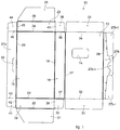
- a shaped sheet 10 which defines the plane development of a pocket-sized parallelepiped box 11 ( fig. 2 ), in which to automatically pack small products such as for example cartridges for vaporizers or inhalers for example of tobacco or other substances (so-called cartomizers), or for components of traditional cigarettes or electronic cigarettes, medicine capsules or suchlike, by means of a machine 12 ( fig. 3 ) according to the present invention, comprises a front wall 13 ( figs. 1 and 2 ), with a substantially rectangular shape, for example 55 mm by 95 mm, in which a substantially rectangular window 14 is made and provided with a transparent film.
- the shaped sheet 10 also comprises a part, in particular a rear wall 15, with sizes equal to those of the front wall 13, a first lateral wall 16 with, for example, a width of 15 mm, disposed between the two walls 13 and 15 and connected to the latter by a first pre-creasing 17 and, respectively, by a second pre-creasing 18, which are configured to define the left lateral edges of the box 11 ( fig. 2 ), and the first and second parts, or walls, 27a, 27b ( fig. 1 ), which, when overlapped as described in detail hereafter, define a second lateral wall 27, opposite the first lateral wall 16 of the box 11 ( fig.2 ).
- the shaped sheet 10 also comprises a lower wall 19 ( fig. 1 ) connected to the rear wall 15 by a third pre-creasing 20 and a first fin 21 connected to the lower wall 19 by a fourth pre-creasing 22.
- the pre-creasings 20 and 22 are configured to define the lower edges of the box 11 ( fig. 2 ).
- the shaped sheet 10 also comprises an upper wall 23 ( fig. 1 ) connected to the rear wall 15 by a fifth pre-creasing 24 and a second flap 25 connected to the upper wall 23 by a sixth pre-creasing 26.
- the pre-creasings 24 and 26 are configured to define the upper edges of the box 11 ( fig. 2 ).
- the first part 27a ( fig. 1 ) that defines the second lateral wall 27 of the box 11 ( fig. 2 ) is connected to the rear wall 15 by a seventh pre-creasing 28 and the second part 27b ( fig. 1 ) that defines the second lateral wall 27 ( fig. 2 ) is connected to the front wall 13 by an eighth pre-creasing 29.
- the second lateral wall 27 ( fig. 2 ) is in turn divided by some die-cuts to form a central flap 27b-c ( fig. 1 ) and two side flaps 27b-1.
- the first part 27a of the second lateral wall 27 ( fig. 2 ) is centrally provided with a cut 30 ( fig. 1 ) configured to accommodate a central tooth formed in the central flap 27b-c, for example after the box 11 has been opened for the first time by the user.
- the first opening of the box 11 by the user can be effected by lifting and separating the second part 27b from the first part 27a of the second wall 27 and thus opening the front wall 13, which in fact represents the lid of the box 11, by rotation around the first pre-creasing 17, which thus acts as a hinge.
- the die defining the two lateral flaps 27b-1 is broken, which remain glued to the first part 27a of the second lateral wall 27, while the remaining portion of the second part 27b is pulled and raised by the user as described above.
- a lower fin 31 is connected to the lower part of the front wall 13 along a lower edge 32, and an upper fin 33 is connected to the upper part of the front wall 13 along an upper edge 34.
- two first small fins 35 and 36 are connected to the two smaller sides of the first lateral wall 16 by a ninth pre-creasing 37 located at the bottom and, respectively, by a tenth pre-creasing 38 located at the top: they are configured to be folded by 90° toward the same first lateral wall 16 and glued one to the lower wall 19 and the other, respectively, to the upper wall 23.
- two cuts 39 and 40 are present between the two first small fins 35 and 36 and, respectively, the wall lower 19 and the upper wall 23.
- a third small fin 41 is connected by an eleventh pre-creasing 42 to a smaller side of the lower wall 19 (the one on the left in fig. 1 ) and is configured to be folded by 90° toward the same lower wall 19 and glued to the lower part of the first part 27a of the second lateral wall 27.
- a cut 43 is present between the third small fin 41 and the lower part of the first part 27a of the second lateral wall 27.
- a fourth small fin 44 is connected by a twelfth pre-creasing 45 to a smaller side of the upper wall 23 and is configured to be folded by 90° toward the same upper wall 23 and glued to the upper part of the first part 27a of the second lateral wall 27.
- a cut 46 is present between the third small fin 44 and the upper part of the first part 27a of the second lateral wall 27.
- the machine 12 ( fig. 3 ) comprises a support frame 50 configured to be rested on a support plane P1, consisting, for example, of a floor.
- a support plane P1 consisting, for example, of a floor.
- a first work plane P2 passes, for example horizontal
- a second work plane P3 passes, parallel to the first work plane P2 and located lower than the first one, for example at a distance comprised between about 800 mm and about 1,000 mm from the support plane P1, to allow an operator U to operate on the second work plane P3, standing in safety conditions.
- connection plane P4 passes which is inclined by an angle ⁇ ( fig. 4 ), for example about 60°, with respect to the second work plane P3.
- ⁇ fig. 4
- the machine 12 also comprises a store 53 ( figs. 3 , 4 and 5 ) disposed upstream of the first wheel 51, that is, on the right of it and slightly higher than the first work plane P2.
- the store 53 is configured to keep stacked vertically, or inclined by about 15° to the right, a plurality of shaped sheets 10.
- a removal device 54 of a known type, for example of the type described in the Italian patent application for industrial invention MI2015A000292 , mentioned above, which is configured to take from the bottom one shaped sheet 10 at a time, position it substantially on the first work plane P2, or slightly above it, and deliver it to an associated first translation device 55, also of a known type.
- the first translation device 55 is configured to translate the shaped sheet 10 taken from the store 53 toward the first wheel 51, keeping it parallel to the first work plane P2.
- the machine 12 also comprises a first conveyor belt 56 ( figs. 3 , 4 and 8 ) disposed upstream of the second wheel 52, that is, on the left of it and slightly lower than the second work plane P3.
- the first conveyor belt 56 is configured to selectively transport a plurality of products A ( fig. 3 ) from a loading station, not shown in the drawings, to the second wheel 52 as will be described in detail below.
- the movement of the first conveyor belt 56 is indicated by the arrows F1 in figs. 4 and 8 .
- the first wheel 51 comprises a plurality of radial arms 57, of which in the example provided here there are twelve, each being angularly distant by 30° from the adjacent one.
- each radial arm 57 there is a rigid support member or mandrel 58 ( figs. 4 , 5 , 6 and 7 ) having an L-shaped cross-section and shaped so as to define a flat support surface 59 ( fig. 5 ) and an internal step 60.
- the flat support surface 59 has the same size as the rear wall 15 of the shaped sheet 10, which in the example given here is 55 mm by 95 mm.
- the thickness of each mandrel 58 is equal to the width of the first lateral wall 16 of the shaped sheet 10, which in the example given here is 15 mm. Therefore, each mandrel 58 has substantially the shape and size of the inside of the box 11 to be made.
- the first wheel 51 is configured to rotate incrementally, step by step, in a first direction of rotation SR1, which in this case is counterclockwise, around the first axis of rotation X1, with angular increases, or steps, of 30°, so that each mandrel 58 can move from an initial working position in which it is coplanar to the first work plane P2 and facing toward the first translation device 55, that is, to the right in fig. 3 , to a final working position, in which it is coplanar to the connection plane P4 and facing toward the second wheel 52, passing from the other seven working positions, angularly distant by 30° from each other, so that there are nine working positions of each mandrel 58. Therefore, each mandrel 58, in the example given here, has three non-operating positions between the connection plane P4 and the first work plane P2, in the direction of rotation SR1, in which there is no shaped sheet 10 associated therewith.
- a pressure member 61 ( fig. 5 ) having a pressure surface 62 facing toward the flat support surface 58 of the mandrel 58 and an inclined fin 63 configured to cooperate with the first part 27a of the second lateral wall 27 of the shaped sheet 10 and to push it into the hollow formed by the internal step 60.
- Each pressure member 61 is associated with a command member of a known type, for example electromagnetic, or fluid-dynamic, not shown in the drawings, but easily conceivable for a person of skill in the art, disposed inside the first wheel 51.
- the command member is configured to selectively move the pressure member 61 between an inactive position (shown by dashes in fig. 5 ), in which the latter is distanced from the corresponding mandrel 58, to an operating position (shown by continuous lines in fig.
- each pressure member 61 ( fig.
- the mandrel 58 is configured to be taken, in the first folding step, to the operating position immediately after the rear wall 15 of a shaped sheet 10, with the inner surface facing downward, has been disposed by the first translation device 55 above the flat support surface 59 of the mandrel 58, while the latter is stationary in its initial working position, and then kept in said operating position until the mandrel 58 arrives in its final working position, that is, parallel to the P4 connection plane and facing toward the second wheel 52, as will be described in more detail hereafter when the functioning of the machine 12 is described.
- the machine 12 in correspondence with a first working position of each mandrel 58, that is, when the latter is on a first radial plane PR1 passing through the first axis of rotation X1, which is angularly displaced by 30° in the direction of rotation SR1 with respect to the first work plane P2, comprises a lifting mechanism 64, which in turn comprises an arm 65 rotating around a pin 66 attached to the support frame 50.
- the arm 65 is provided with a tooth 67 configured to cooperate with the lower part of the shaped sheet 10.
- the arm 65 is commanded by a corresponding command member of a known type, for example an electric actuator, not shown in the drawings but easily conceivable for a person of skill in the art, and is configured to rotate and selectively carry its tooth 67 from an inactive position (shown by dashes in fig. 5 ), in which its tooth 67 is below the first radial plane PR1, to an operating position (shown by continuous lines in fig. 5 ), in which its tooth 67 is above the same first radial plane PR1 and raises the second part 27b of the second lateral wall 27 of the shaped sheet 10 until it is taken against a curved tile 68, attached on the support frame 50 (second folding step shown schematically in fig. 11 ).
- a corresponding command member of a known type for example an electric actuator, not shown in the drawings but easily conceivable for a person of skill in the art, and is configured to rotate and selectively carry its tooth 67 from an inactive position (shown by dashes in fig. 5 ), in which
- the machine 12 in correspondence with a second working position of each mandrel 58, when the latter is on the connection plane P4, but on the opposite side to the wheel 52 ( fig. 4 ), that is, displaced angularly by 30° in a counterclockwise direction to the first radial plane PR1, comprises two first gluing devices 69, mounted on the support frame 50, of which only one is visible in the drawings, being aligned one in front of the other on the same transverse plane.
- the curved tile 68 ( figs. 4 and 5 ) acts as a folding member.
- the tile 68 causes the folding by 90° of the first lateral wall 16 of the shaped sheet 10, together with the associated front wall 13 and second part 27b of the second lateral wall 27 with respect to the pre-creasing 18, toward the rear wall 15 (third folding step shown schematically in fig. 12 ).
- the two gluing devices 69 are of a known type, for example, of the type able to quickly inject fast-setting glue C and are configured to inject the glue C on the external part of the two first small fins 35 and 36 (first gluing step shown schematically in fig. 13 ), which are on opposite sides to the first lateral wall 16 of the shaped sheet 10 while the latter is stationary against the outermost flat surface of the mandrel 58 ( fig. 5 ).
- first folding device 70 Associated with the two first gluing devices 69 there is a first folding device 70 ( figs. 3 , 4 and 5 ), which in turn comprises an arm 71 ( fig. 6 ) rotating around a pin 72 attached on the support frame 50
- the arm 71 at one end is provided with a head 73 having a terminal fork provided with two teeth 74 and 75 distanced from each other in a transverse direction by a value slightly above the height of the first lateral wall 16 of the shaped sheet 10, which also corresponds to the width of the mandrel 58 in the transverse direction.
- the first folding device 70 is configured to cooperate with the two first small fins 35 and 36 of the shaped sheet 10 and fold them by 90° toward the flanks of the mandrel 58, that is, toward the same first lateral wall 16 of the shaped sheet 10 (fourth folding step shown schematically in fig. 14 ).
- the arm 71 is commanded by a corresponding command member of a known type, for example an electric actuator, not shown in the drawings, but easily conceivable for a person of skill in the art, and is configured to selectively rotate and take the head 73 from an inactive position, in which its two teeth 74 and 75 are slightly distant from the mandrel 58 (position shown in fig. 6 ) to a lowered operating position, in which the two teeth 74 and 75 are on opposite sides with respect to the latter and press respectively the two first small fins 35 and 36 of the shaped sheet 10 against the flanks of the same mandrel 58.
- a corresponding command member of a known type for example an electric actuator, not shown in
- the machine 12 in correspondence with an angular sector of 60° which extends from the connection plane P4 to a second radial plane PR2 passing through the first axis of rotation X1, comprises a first guide and folding device 76 attached to the support frame 50.
- the angular sector of 60° comprises a third and fourth working position of each mandrel 58.
- the first guide and folding device 76 comprises in turn a curved external wall 77 and two lateral walls 78 parallel to each other, between which the mandrels 58 and the associated shaped sheets 10 pass with a slight play.
- the two lateral walls 78 function as folding elements; in fact, they are configured to fold by 90° toward the mandrel 58 which passes between them, on one side the lower wall 19 of the shaped sheet 10 and the associated first fin 21, and on the other side the upper wall 23 and the associated second fin 25 (fifth folding step shown schematically in fig. 15 ).
- the lower wall 19 is also glued to the small fin 35 and the upper wall 23 is also glued to the small fin 36.
- the function of the external curved wall 77 is to keep the shaped sheet 10 folded and glued as described above, counteracting the centrifugal force generated by the rotation of the first wheel 51.
- the machine 12 in correspondence with a third radial plane PR3 ( fig. 6 ) passing through the first axis of rotation X1, which is angularly displaced by 30° in the direction of rotation SR1 with respect to the second radial plane PR2, and in which each mandrel 58 is in its fifth working position, comprises both a second folding device 79 and a third folding device 80, which are different from each other but both of the known type.
- the second folding device 79 comprises, for example, a pair of lateral arms 81 disposed on a plane parallel to the third radial plane PR3 and just above the surface of the mandrel 58 opposite the flat support surface 59 of the latter.
- the two lateral arms 81 are pivoted on a pin 82 of a command member 83 attached to the support frame 50.
- the command member 83 is of a known type and is configured to bring the lateral arms 81, selectively and together, from an inactive position, in which they are distant from the flanks of the mandrel 58, to an operating position in which they are above the mandrel 58 so as to fold together the first fin 21 and the second fin 25 of the shaped sheet 10 by 90° toward the rear wall 15 and thus make the fins 21 and 25 parallel to the latter (sixth folding step shown schematically in fig. 16 ).
- the third folding device 80 comprises, for example, an arm 84 ( fig. 6 ) rotating around a pin 85 attached to the support frame 50.
- the arm 84 is provided with a blade 86 configured to cooperate with the front wall 13 of the shaped sheet 10 and push it toward the third radial plane PR3.
- the arm 84 is commanded by a corresponding command member, of a known type, for example an electric actuator, not shown in the drawings, but easily conceivable for a person of skill in the art, and is configured to rotate and selectively take its blade 86 from an inactive position, in which the latter is displaced toward the left, distant from the mandrel 58, to an operating position, in which the blade 86 is above the latter and pushes the front wall 13 of the sheet 10 toward the mandrel 58 (seventh folding step shown schematically in fig. 17 ), thus taking it above the two fins 21 and 25 just folded by the second folding device 79. Together with the front wall 13, the lower fin 31 and the upper fin 33 are also obviously lowered, as well as the second part 27b of the second lateral wall 27 of the shaped sheet 10.
- a corresponding command member of a known type, for example an electric actuator, not shown in the drawings, but easily conceivable for a person of skill in the art, and is configured to rotate and selectively take its blade
- the machine 12 In correspondence with the connection plane P4 ( fig. 7 ), where each mandrel 58 is in its final working position, that is, facing toward the second wheel 52, the machine 12 also comprises a second translation device 87, analogous to the first translation device 55 and mounted on the support frame 50.
- the second translation device 87 is configured to translate the shaped sheet 10, which is already taking the shape of the box 11, toward the second wheel 52, keeping it parallel to the connection plane P4.
- the translation device 87 therefore transfers the shaped sheet 10 from the first wheel 51 to the second wheel 52 in a radial direction.
- Ring direction means the direction defined by those two particular spokes, respectively of the first wheel 51 and of the second wheel 52, which are aligned with each other and extend along the connection plane P4 (as visible in fig. 7 , see the line of dots and long dashes that defines the connection plane P4).
- Two second gluing devices 88 are mounted on the support frame 50 between the two wheels 51 and 52 in correspondence with the connection plane P4.
- the two second gluing devices 88 are configured to selectively inject the glue C on the bottom fin 31 and the upper fin 33 of the shaped sheet 10, and more specifically on the surfaces of the latter facing toward the lower wall 19 and respectively toward the upper wall 23 (second gluing step shown schematically in fig. 18 ).
- the second wheel 52 comprises a plurality of containers, or pockets 91 ( fig. 8 ), of which there are twelve in the example provided here, each being angularly distant by 30° from the adjacent one.
- Each container 91 comprises two parallel walls that define a cavity 92 in the form of a parallelepiped, but open on the smaller sides, and configured to receive the partially folded shaped sheet 10, as shown above, arriving from the first wheel 51 and translated by the second translation device 87.
- the sizes of each cavity 92 are substantially the same as those of the box 11 to be made, which in the example given here are 55 mm x 95 mm x 15 mm.
- the first wheel 52 is also configured to rotate incrementally, step by step, in synchrony with the first wheel 51, in a second direction of rotation SR2, which in this case is also anticlockwise, around the second axis of rotation X2, with angular increases, or steps, of 30°.
- each container 91 can move from an initial working position in which it is coplanar with the connection plane P4 and facing toward the first wheel 51, to a final working position in which, after a rotation of 300° in the direction of rotation SR2, is coplanar to the second work plane P3 and facing toward the left, passing from nine other intermediate working positions, angularly distant by 30° from each other. Therefore, each container 91 has eleven working positions and only one non-operating position, in which there is no shaped sheet 10 or box 11 inside it, that is, between the second work plane P3 and the connection plane P4, in the direction of rotation SR2.
- the rotation of the two wheels 51 and 52 is selectively commanded by command members of any known type and not shown in the drawings, for example, stepper-type electric motors.
- the machine 12 comprises a second guide and folding device 93 attached to the support frame 50.
- the second guide and folding device 93 in turn comprises two lateral walls 94 and 95 parallel to each other, between which the containers 91 and the associated shaped sheets 10 pass with a slight play.
- the two lateral walls 94 and 95 function as folding elements; they are configured to fold by 90° toward the cavity 92 of the container 91 that is passing between them, respectively the lower fin 31 and the upper fin 33 of the shaped sheet 10 (eighth folding step shown schematically in fig. 19 ).
- the bottom fin 31, already provided with glue C is glued to the lower wall 19 and the upper fin 33, also already provided with glue C, is glued to the upper wall 23.
- the machine 12 comprises two third gluing devices 96 mounted on the support frame 50, of which only one is visible in the drawings, since the two third gluing devices 96 are aligned one in front of the other on the same transverse axis X3 parallel to the two axes of rotation X1 and X2.
- the two third gluing devices 96 are also analogous to the first gluing devices 69 and are configured to inject glue C on the external part of the third small fin 41 and the fourth small fin 44 of the shaped sheet 10 (third gluing step shown schematically in fig. 20 ).
- the machine 12 comprises a spreading device 97 mounted on the support frame 50.
- the spreading device 97 in turn comprises an arm 98 ( figs. 4 and 8 ) rotating around a pin 99 attached on the support frame 50.
- the arm 98 is provided with a shaped head 100 configured to cooperate with both the first part 27a and the second part 27b of the second lateral wall 27, and also with the two small fins 41 and 44 opposite each other of the shaped sheet 10 ( figs. 1 and 21 ).
- the arm 98 is commanded by a corresponding command member of a known type, for example an electric actuator, not shown in the drawings but easily conceivable for a person of skill in the art, and is configured to rotate and selectively take its shaped head 100 from an inactive position in which the latter is displaced to the left, distant from the container 91, to an operating position, in which the shaped head 100 is with its terminal end slightly inside the box 11 which is being formed with the shaped sheet 10 ( fig. 8 ) in order to spread simultaneously toward the outside both the first part 27a of the second lateral wall 27, the second part 27b of the second lateral wall 27 and the third small fin 41 and the fourth small fin 44 (spreading step shown schematically in fig. 21 ).
- a corresponding command member of a known type for example an electric actuator, not shown in the drawings but easily conceivable for a person of skill in the art, and is configured to rotate and selectively take its shaped head 100 from an inactive position in which the latter is displaced to the left, distant from the
- the machine 12 comprises a third translation device 101 ( fig. 8 ), also analogous to the first translation device 55 and mounted on the support frame 50.
- the third translation device 101 is configured to translate one product A at a time from the right end of the first conveyor belt 56 inside the shaped sheet 10, which is already taking the shape of the box 11, when the corresponding container 91 is in a fourth working position, which is displaced angularly by 30° in the direction of rotation SR2 with respect to the fifth radial plane PR5, so that the container 91 is coplanar with the second work plane P3.
- the third translation device 101 translates the product A from the first conveyor belt 56 and introduces it inside the box 11 which is being formed (introduction step shown schematically in fig. 22 ).
- a fourth folding device 102 is mounted, below the first conveyor belt 56, and a fifth folding device 103, above the first conveyor belt 56.
- the fourth folding device 102 is substantially analogous to the second folding device 79 and comprises, for example, a pair of lateral arms 104 disposed on a plane perpendicular to the second work plane P3.
- the two lateral arms 104 are pivoted on a pin 105 of a command member 106 attached to the support frame 50.
- the command member 106 is of a known type and is configured to take the two lateral arms 104, selectively and together, from an inactive position in which they are distanced from each other to allow the passage of the product A from the first conveyor belt 56 inside the shaped sheet 10, to an operating position in which they are close to each other, so as to fold together the third small fin 41 and the fourth small fin 44 of the shaped sheet 10, previously provided with the glue C, by 90° toward the inside, and thus make the same fins 41 and 44 parallel to the first lateral wall 16 (ninth folding step shown schematically in fig. 23 ).
- the fifth folding device 103 is analogous to the third folding device 80 and comprises, for example, an arm 107 rotating around a pin 108 attached on the support frame 50.
- the arm 107 is provided with a blade 109 configured to cooperate with the first part 27a of the second lateral wall 27 of the shaped sheet 10, which is in an upwardly spread position, and push it downward until it is in the vertical position.
- the arm 107 is commanded by a corresponding command member of a known type, for example an electric actuator, not shown in the drawings, but easily conceivable for a person of skill in the art, and is configured to rotate and selectively take its blade 109 from an inactive position in which the latter is raised and distant from the second work plane P3, to an operating position in which the blade 109 is lowered and folds downward the first part 27a of the second lateral wall 27 of the shaped sheet 10, which was spread upward (tenth folding step shown schematically in fig. 24 ), thus taking it above the first small fin 41 and the fourth small fin 44 just folded by the fourth folding device 102.
- the third small fin 41 and the fourth small fin 44 already provided with glue C, are glued to the first part 27a of the second lateral wall 27.
- a first circular wall 110 ( fig. 8 ), coaxial to the second axis of rotation X2, is mounted fixed on the support frame 50 just below the left part of the second wheel 52 and develops for a circular sector of about 90°, which, starting from the second work plane P3, in the direction of rotation SR2, comes to a sixth radial plane PR6, in which each container 91 is in a seventh working position.
- the function of the first circular wall 110 is to fold the second part 27b of the second lateral wall 27 of the shaped sheet 10, which was spread downward (eleventh folding step shown schematically in fig. 25 ), while the second wheel 52 rotates and takes the corresponding container 91 from its fourth working position to its seventh working position.
- a fourth gluing device 111 is mounted, configured to inject glue C between the two parts 27a and 27b of the second lateral wall 27 of the shaped sheet 10 (fourth gluing step shown schematically in fig. 26 ) while the corresponding container 91 is in its seventh working position.
- a second circular wall 112 ( fig. 8 ), also coaxial with the second axis of rotation X2, is fixedly mounted on the support frame 50 just below the right part of the second wheel 52 and develops for a circular sector of about 90° which, starting from the sixth radial plane PR6, in the direction of rotation SR2, arrives at the second work plane P3.
- the function of the second circular wall 112 is to keep folded the second part 27b of the second lateral wall 27 of the shaped sheet 10 so that it is glued to the first part 27a of the same second lateral wall 27, to complete the construction of the box 11 with the product A inside (twelfth and last folding step shown schematically in fig. 27 ). Between the first circular wall 110 and the second circular wall 112 there is an opening or interruption 110a, provided to allow to glue the two parts 27a and 27b, as described in detail below.
- an expulsion device 113 is mounted, configured to selectively expel the box 11 from the corresponding container 91 which is in its final working position, coplanar to the second work plane P3.
- the expulsion device 113 comprises a pair of removal wheels 114, of which only one is visible in the drawings, since they are aligned one in front of the other.
- the two removal wheels 114 are configured to contact the lower fin 31 and the upper fin 33 of the shaped sheet 10, which now form the upper and lower surface of the box 11, respectively, and which in this position are located in correspondence with the lateral apertures of the cavity 92 of the container 91.
- Each removal wheel 114 is mounted at the upper end of a vertical shaft 115 selectively rotatable by means of a command member 116 of a known type, for example an electric motor.
- a second conveyor belt 117 Downstream of the expulsion device 113 there is a second conveyor belt 117 ( fig. 3 ), configured to convey the boxes 11 already packaged outside the machine 12, in the direction of movement indicated by arrow F2 ( fig. 4 ).
- the various electromechanical components of the machine 12 are controlled and commanded by a programmable processor of the known type and not shown in the drawings, which can be disposed, for example, inside a compartment 118 ( fig. 3 ).
- a shaped sheet 10 is taken from the store 53 ( figs. 3 , 4 and 5 ) and translated to the mandrel 58, which is located on the first work plane P2 and which in the continuation of the explanation will be called "the mandrel 58".
- the folding of the first part 27a of the second lateral wall 27 of the shaped sheet 10 is carried out by the presser member 61.
- the first wheel 51 is then rotated by 30° in the first direction of rotation SR1, thus taking the mandrel 58 into its first working position coplanar to the first radial plane PR1 ( fig. 5 ).
- the lifting device 64 performs the lifting and the partial folding of the second part 27b of the second lateral wall 27 of the shaped sheet 10 (second folding step shown schematically in fig. 11 ).
- the first wheel 51 is then made to rotate ( fig. 5 ) by another 30° in the first direction of rotation SR1, thus taking the mandrel 58 to its second working position coplanar to the connection plane P4.
- This causes the folding of the first lateral wall 16 and the front wall 13 of the shaped sheet 10 by the curved tile 68 (third folding step shown schematically in fig. 12 ).
- the two first gluing devices 69 are actuated, which inject glue C on the first small fins 35 and 36 of the shaped sheet 10 (first gluing step shown schematically in fig. 13 ) and immediately after the first folding device 70, which folds the same small first fins 35 and 36 (fourth folding step shown schematically in fig. 14 ).
- the first wheel 51 is made to rotate by another 90° in the first direction of rotation SR1, thus taking the mandrel 58 ( fig. 6 ) to its fifth working position, in which it is coplanar to the third radial plane PR3.
- This rotation causes the folding of the lower wall 19 and of the upper wall 23 of the shaped sheet 10 by the two lateral walls 78 (fifth folding step shown schematically in fig. 15 ).
- the second folding device 79 is first actuated, which folds the first fin 21 and the second fin 25 of the shaped sheet 10 (sixth folding step shown schematically in fig. 16 ), and then the third folding device 80, which folds the front wall 13 of the shaped sheet 10 (seventh folding step shown schematically in fig. 17 ).
- the first wheel 51 is made to rotate by another 90° in the first direction of rotation SR1, thus taking the mandrel 58 ( fig. 7 ) to its final working position, in which it is coplanar to the connection plane P4 and facing toward the second wheel 52.
- the second translation device 87 is actuated, which performs the translation of the shaped sheet 10 from the mandrel 58 to the cavity 92 of the container 91 which at that moment is on the same connection plane P4 and which in the continuation of the explanation will be called "the container 91".
- the two second gluing devices 88 are also actuated, which inject glue C on the bottom fin 31 and on the upper fin 33 of the shaped sheet 10 (second gluing step shown schematically in fig. 18 ).
- the second wheel 52 ( fig. 8 ) is made to rotate in synchrony and at the same angular velocity as the first wheel 51, also with angular increases of 30° in the second direction of rotation SR2.
- the second wheel 52 with two successive steps of 30° each, is made to rotate by 60° in the second direction of rotation SR2, thus taking the container 91 to its second working position, in which it is coplanar with the fourth radial plane PR4.
- This rotation causes the folding of the lower fin 31 and the upper fin 33 of the shaped sheet 10 by the two lateral walls 94 and 95 (eighth folding step shown schematically in fig. 19 ).
- the two third gluing devices 96 are also actuated, which inject glue C on the external part of the third small fin 41 and the fourth small fin 44 of the shaped sheet 10 (third gluing step shown schematically in fig. 20 ).
- the second wheel 52 is then made to rotate by another step of 30° in the second direction of rotation SR2, thus taking the container 91 to its third working position, in which it is coplanar to the fifth radial PR5 plane.
- the spreading device 97 is actuated, which spreads the four parts of the shaped sheet 10 that define the closure of the box 11 that is forming, that is, the first part 27a and the second part 27b of the second lateral wall 27, and also the third small fin 41 and the fourth small fin 44 (spreading step shown schematically in fig. 21 ).
- This spreading step is very useful to allow an easier insertion, without any blockages, of the product A inside the box 11 that is being formed.
- the second wheel 52 ( fig. 8 ) is then made to rotate by another step of 30° in the second direction of rotation SR2, thus taking the container 91 to its fourth working position, in which it is coplanar to the second work plane P3.
- the third translation device 101 is actuated first, which translates a product A from the first conveyor belt 56 and introduces it into the box 11 which is being formed (the introduction step shown schematically in fig. 22 )
- the fourth folding device 102 is actuated ( fig. 8 ), which folds the third small fin 41 and the fourth small fin 44 of the shaped sheet 10 (ninth folding step shown schematically in fig. 23 )
- the fifth folding device 103 is actuated, which folds downward the first part 27a of the second lateral wall 27 of the shaped sheet 10 (tenth folding step shown schematically in fig. 24 ).
- the second wheel 52 is made to rotate by another 90° in the second direction of rotation SR2, thus taking the container 91 ( fig. 8 ) to its seventh working position, in which it is coplanar to the sixth radial plane PR6.
- This rotation causes the folding of the second part 27b of the second lateral wall 27 of the shaped sheet 10 (tenth folding step shown schematically in fig. 24 ) by the first circular wall 110 (eleventh folding step shown schematically in fig. 25 ).
- the first circular wall 110 and the second circular wall 112 essentially in correspondence with its seventh working position, there is the above mentioned opening or interruption 110a, so that the second part 27b of the second lateral wall 27 is no longer kept folded and tends to elastically reopen temporarily.
- This temporary reopening of the second part 27b of the second lateral wall 27 gives the opportunity to dispense the glue C to the first part 27a of the second lateral wall 27, for gluing with the second part 27b of the second lateral wall 27, in particular, for example, with the lateral flaps 27b-1 of the second part 27b of the second lateral wall 27.
- the container 91 fig. 8
- the second part 27b of the second lateral wall 27 meets the second circular wall 112 which renews the folding, closing it on the first part 27a of the second lateral wall 27 and thus allowing to obtain the gluing (twelfth and last folding step shown schematically in fig. 27 ).
- the gluing of the first part 27a to the second part 27b defines the second wall 27 of the box 11.
- the second wheel 52 is made to rotate by another 90°, in the second direction of rotation SR2, thus taking the container 91 to its final working position, in which it is coplanar to the second work plane P3, toward the second conveyor belt 117.
- the box 11 is now complete.
- the expulsion device 113 is therefore actuated, which by means of the removal wheels 114 expel the box 11 from the container 91 and deposit it on the second conveyor belt 117.
- the container 91 freed of its contents, with another two successive rotations of the second wheel 52 by 30° each, in the second direction of rotation SR2, returns to its initial working position, coplanar with the connection plane P4, in front of the first wheel 51, to start a new cycle.
Description
- The field of application of the present invention is that of machines to automatically pack products, especially small ones, such as for example tobacco-based products such as capsules, cartridges or suchlike, or pharmaceuticals or other, in boxes preferably of pocketable size such as for example boxes for cartridges for vaporizers or inhalers for example of tobacco or other substances (so-called cartomizers), or for components of traditional cigarettes or electronic cigarettes, or boxes of medicines packed in blister packs or suchlike.
- In the field of automatic packing machines, several machines and various methods are known to automatically pack products, especially small ones, such as for example tobacco-based products such as capsules, cartridges or suchlike, or pharmaceutical products or other, in boxes preferably of pocketable size, such as for example boxes for cartridges for vaporizers or inhalers for example of tobacco or other substances (so-called cartomizers), or for components of traditional cigarettes or electronic cigarettes, or boxes of medicines packed in blister packs or suchlike.
- One of these known machines, and the associated method, are disclosed in the Italian patent application for industrial invention
MI2015A000292 - This known machine comprises a wheel for transferring shaped sheets, known as blanks, from an input station to an output station, between which a determinate transfer path develops. In an intermediate position between the input station and the output station, there is a pre-bending and folding station with which a device for working the blanks is associated, which comprises a single-body structure in which there are several pre-bending, pre-folding and complete folding members.
- This known machine, although it represents an innovation with respect to the prior art of previously known machines, has limits with regard to productivity, because all the different and complex folding operations or steps must be performed and executed sequentially on or in association with the single wheel.
- Another known packing machine is described in the patent application
US-A-4,548,019 . The packing machine described in this document comprises a first wheel and a second wheel which feed a wrapper intended to form a packet. Various folding and gluing stations are associated with the wheels, and work in succession on the wrapper to progressively form said packet. - This machine also has significant limits because it has a very complicated structure, and is also bulky and expensive.
- There is therefore a need to perfect a machine and a corresponding method that allow to automatically make boxes, preferably pocket-sized, to automatically pack products, especially small ones, into preferably pocketable boxes, which can overcome at least one of the disadvantages of the state of the art.
- In particular, one purpose of the present invention is to provide a machine and perfect a method that allow to automatically produce boxes, preferably pocket-sized, starting from shaped flat sheets, and to pack in them products of a size suitable for that of the boxes, before the complete closure of the latter, in which a high hourly production can be obtained, and at the same time in which both the machine and the method, are reliable, safe and economically advantageous.
- The Applicant has devised, tested and embodied the present invention to overcome the shortcomings of the state of the art and to obtain these and other purposes and advantages.
- Other limitations and disadvantages of conventional solutions and technologies will be clear to a person of skill after reading the remaining part of the present description with reference to the drawings and the description of the embodiments that follow, although it is clear that the description of the state of the art connected to the present description must not be considered an admission that what is described here is already known from the state of the prior art.
- The present invention is set forth and characterized in the independent claims, while the dependent claims describe other characteristics of the invention or variants to the main inventive idea.
- In accordance with the above purposes, embodiments described here concern a machine to make boxes each starting from a shaped sheet with at least a plurality of walls and fins and to automatically pack products in each of the boxes, during the production of the latter.
- According to one embodiment, the machine is defined according to
claim 1. - According to another embodiment, the first radial support elements each comprise a mandrel of the rigid type, with substantially the shape of a parallelepiped with sizes corresponding to those of the inside of each of the boxes, so that the shaped sheet can fold resting on the external surfaces of the mandrel, without deforming.
- According to another embodiment, the second radial support elements each comprise a container that defines a cavity with substantially the shape of a parallelepiped with sizes corresponding to those of the outside of each of the boxes, so that said other folds can be made on the shaped sheet and so that during the shaping step at least one of the products can be inserted inside each of the boxes, before each of the boxes is completed and closed.
- In accordance with another embodiment, the determinate radial working position of each of the first radial support elements corresponds to a final working position of the latter, and the determinate radial working position of each of the second radial support elements corresponds to an initial working position of the latter.
- In accordance with another embodiment, the machine also comprises a plurality of presser members mounted on the first rotating member and each associated with one of the first radial support elements in order to selectively press a part of the shaped sheet against a surface of the corresponding radial support element.
- According to another embodiment, the first folding means comprise a first plurality of folding devices mounted in fixed positions on a support frame of the machine and associated with the first plurality of radial working positions of the first radial support elements.
- In accordance with another embodiment the second folding means comprise a second plurality of folding devices mounted in fixed positions on the support frame of the machine and associated with the second plurality of radial working positions of the second radial support elements.
- According to another embodiment, the machine also comprises spreading means associated with the second rotating member and configured to temporarily spread one part of the fins of the shaped sheet before the introduction of at least one of the products into each of the boxes during the production step.
- In accordance with another embodiment, the machine also comprises gluing means, associated both with the first rotating member and also with the second rotating member and configured to selectively inject glue onto determinate parts of the shaped sheet in association with the first and second folding means.
- Other embodiments concern a method to make boxes each starting from a shaped sheet with at least a plurality of walls and fins, and to automatically pack products in each of the boxes during their production.
- According to one embodiment, the method is defined according to
claim 11. - Some embodiments also concern a box containing products obtained by a method as in the present description, starting from a shaped sheet with at least a plurality of walls and fins.
- These and other aspects, characteristics and advantages of the present disclosure will be better understood with reference to the following description, drawings and attached claims. The drawings, which are integrated and form part of the present description, show some forms of embodiment of the present invention, and together with the description, are intended to describe the principles of the disclosure.
- The various aspects and characteristics described in the present description can be applied individually where possible. These individual aspects, for example aspects and characteristics described in the specification or in the attached dependent claims, can be the object of divisional applications.
- It is understood that any aspect or characteristic that is discovered, during the patenting process, to be already known, shall not be claimed and shall be the object of a disclaimer.
- These and other characteristics of the present invention will become apparent from the following description of some embodiments, given as a non-restrictive example with reference to the attached drawings wherein:
-
fig. 1 is a plan view of a shaped sheet, also called blank, that defines the flat development of a box of pocketable size, schematized infig. 2 , in which to automatically pack products of small sizes, by means of a machine and/or using a method according to the present invention; -
fig. 2 is a three-dimensional view of a box made with the shaped sheet infig. 1 ; -
fig. 3 is a front view of a machine according to the present invention; -
fig. 4 is an enlarged detail of the machine infig. 3 ; -
fig. 5 is a detail of the machine infig. 3 , more enlarged than that infig. 4 ; -
fig. 6 is another detail of the machine infig. 3 on the same enlarged scale as that infig.5 ; -
fig. 7 is another detail of the machine infig. 3 on a smaller enlarged scale than that infigs. 5 and 6 ; -
fig. 8 is yet another detail of the machine infig. 3 on a smaller enlarged scale than that infig. 7 ; -
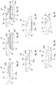
fig. 9 is a perspective and schematic view of the shaped sheet infig. 1 with its internal surface facing upward and in an initial position, before the folding steps by the machine infig. 3 have been started; -
fig. 10 is a perspective and schematic view of the shaped sheet infig. 1 after a first folding step; -
fig. 11 is a perspective and schematic view of the shaped sheet infig. 1 after a second folding step; -
fig. 12 is a perspective and schematic view of the shaped sheet infig. 1 after a third folding step; -
fig. 13 is a perspective and schematic view of the shaped sheet infig. 1 after a first gluing step; -
fig. 14 is a perspective and schematic view of the shaped sheet infig. 1 after a fourth folding step; -
fig. 15 is a perspective and schematic view of the shaped sheet infig. 1 after a fifth folding step; -
fig. 16 is a perspective and schematic view of the shaped sheet infig. 1 after a sixth folding step; -
fig. 17 is a perspective and schematic view of the shaped sheet infig. 1 after a seventh folding step; -
fig. 18 is a perspective and schematic view of the shaped sheet infig. 1 after a second gluing step; -
fig. 19 is a perspective and schematic view of the shaped sheet infig. 1 after an eighth folding step; -
fig. 20 is a perspective and schematic view of the shaped sheet infig. 1 after a third gluing step; -
fig. 21 is a perspective and schematic view of the shaped sheet infig. 1 after a spreading step of the parts at the sides of the access aperture to the box being formed; -
fig. 22 is a perspective and schematic view of the shaped sheet infig. 1 after an introduction step, during which a product is inserted into the box being formed; -
fig. 23 is a perspective and schematic view of the shaped sheet infig. 1 after a ninth folding step, to begin to close the box with the product inside; -
fig. 24 is a perspective and schematic view of the shaped sheet infig. 1 after a tenth folding step, to continue to close the box with the product inside, folding a first part of a lateral wall; -
fig. 25 is a perspective and schematic view of the shaped sheet infig. 1 after an eleventh folding step, to continue to close the box with the product inside, folding a second part of a lateral wall infig. 24 ; -
fig. 26 is a perspective and schematic view of the shaped sheet infig. 1 after a fourth gluing step to glue together the two parts of the lateral wall infig. 24 and to seal the box with the product inside; -
fig. 27 is a perspective and schematic view of a completed and closed box, after a twelfth and final folding step, made with the shaped sheet infig. 1 and into which the packed product is inserted. - To facilitate comprehension, the same reference numbers have been used, where possible, to identify identical common elements in the drawings. It is understood that elements and characteristics of one embodiment can conveniently be incorporated into other embodiments without further clarifications.
- We shall now refer in detail to the various embodiments of the present invention, of which one or more examples are shown in the attached drawings. Each example is supplied by way of illustration of the invention and shall not be understood as a limitation thereof. For example, the characteristics shown or described insomuch as they are part of one embodiment can be adopted on, or in association with, other embodiments to produce another embodiment. It is understood that the present invention shall comprise all such modifications and variants.
- Before describing these embodiments, we must also clarify that the present description is not limited in its application to details of the construction and disposition of the components as described in the following description using the attached drawings. The present description can provide other embodiments and can be obtained or executed in various other ways. We must also clarify that the phraseology and terminology used here is for the purposes of description only, and cannot be considered as limitative.
- We must clarify that in the present description and in the claims the terms high, low, vertical, horizontal, upper, lower, right, left, external and internal, with their declinations, have the sole function of illustrating the present invention better with reference to the drawings, and must not be used in any way to limit the scope of the invention itself, or the field of protection as defined by the claims. For example, the term horizontal is intended to mean a plane that can be both parallel to the line of the horizon and also sub-horizontal, that is inclined, even by several degrees, for example up to 15°, compared to the line of the horizon.
- With reference to
fig. 1 , ashaped sheet 10, which defines the plane development of a pocket-sized parallelepiped box 11 (fig. 2 ), in which to automatically pack small products such as for example cartridges for vaporizers or inhalers for example of tobacco or other substances (so-called cartomizers), or for components of traditional cigarettes or electronic cigarettes, medicine capsules or suchlike, by means of a machine 12 (fig. 3 ) according to the present invention, comprises a front wall 13 (figs. 1 and2 ), with a substantially rectangular shape, for example 55 mm by 95 mm, in which a substantiallyrectangular window 14 is made and provided with a transparent film. The shapedsheet 10 also comprises a part, in particular arear wall 15, with sizes equal to those of thefront wall 13, a firstlateral wall 16 with, for example, a width of 15 mm, disposed between the twowalls first pre-creasing 17 and, respectively, by asecond pre-creasing 18, which are configured to define the left lateral edges of the box 11 (fig. 2 ), and the first and second parts, or walls, 27a, 27b (fig. 1 ), which, when overlapped as described in detail hereafter, define a secondlateral wall 27, opposite the firstlateral wall 16 of the box 11 (fig.2 ). - The shaped
sheet 10 also comprises a lower wall 19 (fig. 1 ) connected to therear wall 15 by athird pre-creasing 20 and afirst fin 21 connected to thelower wall 19 by afourth pre-creasing 22. The pre-creasings 20 and 22 are configured to define the lower edges of the box 11 (fig. 2 ). - The shaped
sheet 10 also comprises an upper wall 23 (fig. 1 ) connected to therear wall 15 by afifth pre-creasing 24 and asecond flap 25 connected to theupper wall 23 by asixth pre-creasing 26. The pre-creasings 24 and 26 are configured to define the upper edges of the box 11 (fig. 2 ). Thefirst part 27a (fig. 1 ) that defines the secondlateral wall 27 of the box 11 (fig. 2 ) is connected to therear wall 15 by aseventh pre-creasing 28 and thesecond part 27b (fig. 1 ) that defines the second lateral wall 27 (fig. 2 ) is connected to thefront wall 13 by aneighth pre-creasing 29. Thesecond side 27b (fig. 1 ) of the second lateral wall 27 (fig. 2 ) is in turn divided by some die-cuts to form acentral flap 27b-c (fig. 1 ) and twoside flaps 27b-1. Thefirst part 27a of the second lateral wall 27 (fig. 2 ) is centrally provided with a cut 30 (fig. 1 ) configured to accommodate a central tooth formed in thecentral flap 27b-c, for example after thebox 11 has been opened for the first time by the user. - The first opening of the
box 11 by the user can be effected by lifting and separating thesecond part 27b from thefirst part 27a of thesecond wall 27 and thus opening thefront wall 13, which in fact represents the lid of thebox 11, by rotation around thefirst pre-creasing 17, which thus acts as a hinge. By this action, the die defining the twolateral flaps 27b-1 is broken, which remain glued to thefirst part 27a of the secondlateral wall 27, while the remaining portion of thesecond part 27b is pulled and raised by the user as described above. - A
lower fin 31 is connected to the lower part of thefront wall 13 along alower edge 32, and anupper fin 33 is connected to the upper part of thefront wall 13 along anupper edge 34. - Furthermore, two first
small fins lateral wall 16 by a ninth pre-creasing 37 located at the bottom and, respectively, by a tenth pre-creasing 38 located at the top: they are configured to be folded by 90° toward the same firstlateral wall 16 and glued one to thelower wall 19 and the other, respectively, to theupper wall 23. In fact, twocuts small fins upper wall 23. - A third
small fin 41 is connected by an eleventh pre-creasing 42 to a smaller side of the lower wall 19 (the one on the left infig. 1 ) and is configured to be folded by 90° toward the samelower wall 19 and glued to the lower part of thefirst part 27a of the secondlateral wall 27. In fact, acut 43 is present between the thirdsmall fin 41 and the lower part of thefirst part 27a of the secondlateral wall 27. - A fourth
small fin 44 is connected by a twelfth pre-creasing 45 to a smaller side of theupper wall 23 and is configured to be folded by 90° toward the sameupper wall 23 and glued to the upper part of thefirst part 27a of the secondlateral wall 27. In fact, acut 46 is present between the thirdsmall fin 44 and the upper part of thefirst part 27a of the secondlateral wall 27. - The machine 12 (
fig. 3 ) comprises asupport frame 50 configured to be rested on a support plane P1, consisting, for example, of a floor. On thesupport frame 50, mounted rotatably, there is afirst wheel 51 having a first axis of rotation X1, for example horizontal, and asecond wheel 52, disposed lower down and having a second axis of rotation X2 parallel to the first axis of rotation X1. - Through the first axis of rotation X1 a first work plane P2 passes, for example horizontal, while through the second axis of rotation X2 a second work plane P3 passes, parallel to the first work plane P2 and located lower than the first one, for example at a distance comprised between about 800 mm and about 1,000 mm from the support plane P1, to allow an operator U to operate on the second work plane P3, standing in safety conditions.
- Between the two axes of rotation X1 and X2 a connection plane P4 passes which is inclined by an angle α (
fig. 4 ), for example about 60°, with respect to the second work plane P3. The distance between the two axes of rotation X1 and X2, in the example given here, is about 430 mm. - The
machine 12 also comprises a store 53 (figs. 3 ,4 and5 ) disposed upstream of thefirst wheel 51, that is, on the right of it and slightly higher than the first work plane P2. Thestore 53 is configured to keep stacked vertically, or inclined by about 15° to the right, a plurality of shapedsheets 10. - Associated with the bottom of the
store 53 there is aremoval device 54 of a known type, for example of the type described in the Italian patent application for industrial inventionMI2015A000292 sheet 10 at a time, position it substantially on the first work plane P2, or slightly above it, and deliver it to an associatedfirst translation device 55, also of a known type. Thefirst translation device 55 is configured to translate the shapedsheet 10 taken from thestore 53 toward thefirst wheel 51, keeping it parallel to the first work plane P2. - The
machine 12 also comprises a first conveyor belt 56 (figs. 3 ,4 and8 ) disposed upstream of thesecond wheel 52, that is, on the left of it and slightly lower than the second work plane P3. Thefirst conveyor belt 56 is configured to selectively transport a plurality of products A (fig. 3 ) from a loading station, not shown in the drawings, to thesecond wheel 52 as will be described in detail below. The movement of thefirst conveyor belt 56 is indicated by the arrows F1 infigs. 4 and8 . - The
first wheel 51 comprises a plurality ofradial arms 57, of which in the example provided here there are twelve, each being angularly distant by 30° from the adjacent one. - In the most peripheral part of each
radial arm 57 there is a rigid support member or mandrel 58 (figs. 4 ,5 ,6 and7 ) having an L-shaped cross-section and shaped so as to define a flat support surface 59 (fig. 5 ) and aninternal step 60. Theflat support surface 59 has the same size as therear wall 15 of the shapedsheet 10, which in the example given here is 55 mm by 95 mm. The thickness of eachmandrel 58 is equal to the width of the firstlateral wall 16 of the shapedsheet 10, which in the example given here is 15 mm. Therefore, eachmandrel 58 has substantially the shape and size of the inside of thebox 11 to be made. - The
first wheel 51 is configured to rotate incrementally, step by step, in a first direction of rotation SR1, which in this case is counterclockwise, around the first axis of rotation X1, with angular increases, or steps, of 30°, so that eachmandrel 58 can move from an initial working position in which it is coplanar to the first work plane P2 and facing toward thefirst translation device 55, that is, to the right infig. 3 , to a final working position, in which it is coplanar to the connection plane P4 and facing toward thesecond wheel 52, passing from the other seven working positions, angularly distant by 30° from each other, so that there are nine working positions of eachmandrel 58. Therefore, eachmandrel 58, in the example given here, has three non-operating positions between the connection plane P4 and the first work plane P2, in the direction of rotation SR1, in which there is noshaped sheet 10 associated therewith. - On the
first wheel 51, in correspondence with eachmandrel 58, there is a pressure member 61 (fig. 5 ) having apressure surface 62 facing toward theflat support surface 58 of themandrel 58 and aninclined fin 63 configured to cooperate with thefirst part 27a of the secondlateral wall 27 of the shapedsheet 10 and to push it into the hollow formed by theinternal step 60. - Each
pressure member 61 is associated with a command member of a known type, for example electromagnetic, or fluid-dynamic, not shown in the drawings, but easily conceivable for a person of skill in the art, disposed inside thefirst wheel 51. The command member is configured to selectively move thepressure member 61 between an inactive position (shown by dashes infig. 5 ), in which the latter is distanced from the correspondingmandrel 58, to an operating position (shown by continuous lines infig. 5 ), in which it presses the internal surface of therear wall 15 of the shapedsheet 10 against theflat support surface 59 of themandrel 58 and at the same time, with itsinclined fin 63, folds thefirst part 27a of the secondlateral wall 27 of the shapedsheet 10 by about 45° (first folding step shown schematically infig. 10 ). In particular, each pressure member 61 (fig. 5 ) is configured to be taken, in the first folding step, to the operating position immediately after therear wall 15 of a shapedsheet 10, with the inner surface facing downward, has been disposed by thefirst translation device 55 above theflat support surface 59 of themandrel 58, while the latter is stationary in its initial working position, and then kept in said operating position until themandrel 58 arrives in its final working position, that is, parallel to the P4 connection plane and facing toward thesecond wheel 52, as will be described in more detail hereafter when the functioning of themachine 12 is described. - The
machine 12, in correspondence with a first working position of eachmandrel 58, that is, when the latter is on a first radial plane PR1 passing through the first axis of rotation X1, which is angularly displaced by 30° in the direction of rotation SR1 with respect to the first work plane P2, comprises alifting mechanism 64, which in turn comprises anarm 65 rotating around apin 66 attached to thesupport frame 50. Thearm 65 is provided with atooth 67 configured to cooperate with the lower part of the shapedsheet 10. In particular, thearm 65 is commanded by a corresponding command member of a known type, for example an electric actuator, not shown in the drawings but easily conceivable for a person of skill in the art, and is configured to rotate and selectively carry itstooth 67 from an inactive position (shown by dashes infig. 5 ), in which itstooth 67 is below the first radial plane PR1, to an operating position (shown by continuous lines infig. 5 ), in which itstooth 67 is above the same first radial plane PR1 and raises thesecond part 27b of the secondlateral wall 27 of the shapedsheet 10 until it is taken against acurved tile 68, attached on the support frame 50 (second folding step shown schematically infig. 11 ). - The machine 12 (
fig. 4 ), in correspondence with a second working position of eachmandrel 58, when the latter is on the connection plane P4, but on the opposite side to the wheel 52 (fig. 4 ), that is, displaced angularly by 30° in a counterclockwise direction to the first radial plane PR1, comprises twofirst gluing devices 69, mounted on thesupport frame 50, of which only one is visible in the drawings, being aligned one in front of the other on the same transverse plane. - The curved tile 68 (
figs. 4 and5 ) acts as a folding member. In fact, with the rotation of 30° of thefirst wheel 51, which takes eachmandrel 58 from the first working position to the second working position, thetile 68 causes the folding by 90° of the firstlateral wall 16 of the shapedsheet 10, together with the associatedfront wall 13 andsecond part 27b of the secondlateral wall 27 with respect to the pre-creasing 18, toward the rear wall 15 (third folding step shown schematically infig. 12 ). - The two
gluing devices 69 are of a known type, for example, of the type able to quickly inject fast-setting glue C and are configured to inject the glue C on the external part of the two firstsmall fins 35 and 36 (first gluing step shown schematically infig. 13 ), which are on opposite sides to the firstlateral wall 16 of the shapedsheet 10 while the latter is stationary against the outermost flat surface of the mandrel 58 (fig. 5 ). - Associated with the two
first gluing devices 69 there is a first folding device 70 (figs. 3 ,4 and5 ), which in turn comprises an arm 71 (fig. 6 ) rotating around apin 72 attached on thesupport frame 50 Thearm 71 at one end is provided with ahead 73 having a terminal fork provided with twoteeth lateral wall 16 of the shapedsheet 10, which also corresponds to the width of themandrel 58 in the transverse direction. - The
first folding device 70 is configured to cooperate with the two firstsmall fins sheet 10 and fold them by 90° toward the flanks of themandrel 58, that is, toward the same firstlateral wall 16 of the shaped sheet 10 (fourth folding step shown schematically infig. 14 ). In particular, thearm 71 is commanded by a corresponding command member of a known type, for example an electric actuator, not shown in the drawings, but easily conceivable for a person of skill in the art, and is configured to selectively rotate and take thehead 73 from an inactive position, in which its twoteeth fig. 6 ) to a lowered operating position, in which the twoteeth small fins sheet 10 against the flanks of thesame mandrel 58. - Furthermore, the
machine 12, in correspondence with an angular sector of 60° which extends from the connection plane P4 to a second radial plane PR2 passing through the first axis of rotation X1, comprises a first guide andfolding device 76 attached to thesupport frame 50. The angular sector of 60° comprises a third and fourth working position of eachmandrel 58. The first guide andfolding device 76 comprises in turn a curvedexternal wall 77 and twolateral walls 78 parallel to each other, between which themandrels 58 and the associated shapedsheets 10 pass with a slight play. The twolateral walls 78 function as folding elements; in fact, they are configured to fold by 90° toward themandrel 58 which passes between them, on one side thelower wall 19 of the shapedsheet 10 and the associatedfirst fin 21, and on the other side theupper wall 23 and the associated second fin 25 (fifth folding step shown schematically infig. 15 ). In this way, thelower wall 19 is also glued to thesmall fin 35 and theupper wall 23 is also glued to thesmall fin 36. The function of the externalcurved wall 77 is to keep theshaped sheet 10 folded and glued as described above, counteracting the centrifugal force generated by the rotation of thefirst wheel 51. - Furthermore, the
machine 12, in correspondence with a third radial plane PR3 (fig. 6 ) passing through the first axis of rotation X1, which is angularly displaced by 30° in the direction of rotation SR1 with respect to the second radial plane PR2, and in which eachmandrel 58 is in its fifth working position, comprises both asecond folding device 79 and athird folding device 80, which are different from each other but both of the known type. - In particular, the
second folding device 79 comprises, for example, a pair oflateral arms 81 disposed on a plane parallel to the third radial plane PR3 and just above the surface of themandrel 58 opposite theflat support surface 59 of the latter. The twolateral arms 81 are pivoted on apin 82 of acommand member 83 attached to thesupport frame 50. Thecommand member 83 is of a known type and is configured to bring thelateral arms 81, selectively and together, from an inactive position, in which they are distant from the flanks of themandrel 58, to an operating position in which they are above themandrel 58 so as to fold together thefirst fin 21 and thesecond fin 25 of the shapedsheet 10 by 90° toward therear wall 15 and thus make thefins fig. 16 ). - The
third folding device 80 comprises, for example, an arm 84 (fig. 6 ) rotating around apin 85 attached to thesupport frame 50. Thearm 84 is provided with ablade 86 configured to cooperate with thefront wall 13 of the shapedsheet 10 and push it toward the third radial plane PR3. Thearm 84 is commanded by a corresponding command member, of a known type, for example an electric actuator, not shown in the drawings, but easily conceivable for a person of skill in the art, and is configured to rotate and selectively take itsblade 86 from an inactive position, in which the latter is displaced toward the left, distant from themandrel 58, to an operating position, in which theblade 86 is above the latter and pushes thefront wall 13 of thesheet 10 toward the mandrel 58 (seventh folding step shown schematically infig. 17 ), thus taking it above the twofins second folding device 79. Together with thefront wall 13, thelower fin 31 and theupper fin 33 are also obviously lowered, as well as thesecond part 27b of the secondlateral wall 27 of the shapedsheet 10. - In correspondence with the connection plane P4 (
fig. 7 ), where eachmandrel 58 is in its final working position, that is, facing toward thesecond wheel 52, themachine 12 also comprises asecond translation device 87, analogous to thefirst translation device 55 and mounted on thesupport frame 50. Thesecond translation device 87 is configured to translate the shapedsheet 10, which is already taking the shape of thebox 11, toward thesecond wheel 52, keeping it parallel to the connection plane P4. Thetranslation device 87 therefore transfers the shapedsheet 10 from thefirst wheel 51 to thesecond wheel 52 in a radial direction. - "Radial direction" means the direction defined by those two particular spokes, respectively of the
first wheel 51 and of thesecond wheel 52, which are aligned with each other and extend along the connection plane P4 (as visible infig. 7 , see the line of dots and long dashes that defines the connection plane P4). - Two
second gluing devices 88, analogous to thefirst gluing devices 69, are mounted on thesupport frame 50 between the twowheels second gluing devices 88 are configured to selectively inject the glue C on thebottom fin 31 and theupper fin 33 of the shapedsheet 10, and more specifically on the surfaces of the latter facing toward thelower wall 19 and respectively toward the upper wall 23 (second gluing step shown schematically infig. 18 ). - The
second wheel 52 comprises a plurality of containers, or pockets 91 (fig. 8 ), of which there are twelve in the example provided here, each being angularly distant by 30° from the adjacent one. - Each
container 91 comprises two parallel walls that define acavity 92 in the form of a parallelepiped, but open on the smaller sides, and configured to receive the partially folded shapedsheet 10, as shown above, arriving from thefirst wheel 51 and translated by thesecond translation device 87. The sizes of eachcavity 92 are substantially the same as those of thebox 11 to be made, which in the example given here are 55 mm x 95 mm x 15 mm. - The
first wheel 52 is also configured to rotate incrementally, step by step, in synchrony with thefirst wheel 51, in a second direction of rotation SR2, which in this case is also anticlockwise, around the second axis of rotation X2, with angular increases, or steps, of 30°. In this way, eachcontainer 91 can move from an initial working position in which it is coplanar with the connection plane P4 and facing toward thefirst wheel 51, to a final working position in which, after a rotation of 300° in the direction of rotation SR2, is coplanar to the second work plane P3 and facing toward the left, passing from nine other intermediate working positions, angularly distant by 30° from each other. Therefore, eachcontainer 91 has eleven working positions and only one non-operating position, in which there is noshaped sheet 10 orbox 11 inside it, that is, between the second work plane P3 and the connection plane P4, in the direction of rotation SR2. - The rotation of the two
wheels - Furthermore, in correspondence with an angular sector of 300°, which in the direction of rotation SR2 goes from the connection plane P4 to the second work plane P3, the
machine 12 comprises a second guide andfolding device 93 attached to thesupport frame 50. The second guide andfolding device 93 in turn comprises twolateral walls containers 91 and the associated shapedsheets 10 pass with a slight play. The twolateral walls cavity 92 of thecontainer 91 that is passing between them, respectively thelower fin 31 and theupper fin 33 of the shaped sheet 10 (eighth folding step shown schematically infig. 19 ). In this way, thebottom fin 31, already provided with glue C, is glued to thelower wall 19 and theupper fin 33, also already provided with glue C, is glued to theupper wall 23. - Furthermore, in correspondence with a fourth radial plane PR4 (
fig. 8 ) passing through the second axis of rotation X2 and which is angularly displaced by 60° in the direction of rotation SR2 with respect to the connection plane P4, themachine 12 comprises twothird gluing devices 96 mounted on thesupport frame 50, of which only one is visible in the drawings, since the twothird gluing devices 96 are aligned one in front of the other on the same transverse axis X3 parallel to the two axes of rotation X1 and X2. The twothird gluing devices 96 are also analogous to thefirst gluing devices 69 and are configured to inject glue C on the external part of the thirdsmall fin 41 and the fourthsmall fin 44 of the shaped sheet 10 (third gluing step shown schematically infig. 20 ). - In correspondence with a fifth radial plane PR5 (
fig. 8 ) passing through the second axis of rotation X2 and which is angularly displaced by 30° in the direction of rotation SR2 with respect to the fourth radial plane PR4, themachine 12 comprises a spreadingdevice 97 mounted on thesupport frame 50. The spreadingdevice 97 in turn comprises an arm 98 (figs. 4 and8 ) rotating around apin 99 attached on thesupport frame 50. Thearm 98 is provided with ashaped head 100 configured to cooperate with both thefirst part 27a and thesecond part 27b of the secondlateral wall 27, and also with the twosmall fins figs. 1 and21 ). Thearm 98 is commanded by a corresponding command member of a known type, for example an electric actuator, not shown in the drawings but easily conceivable for a person of skill in the art, and is configured to rotate and selectively take itsshaped head 100 from an inactive position in which the latter is displaced to the left, distant from thecontainer 91, to an operating position, in which the shapedhead 100 is with its terminal end slightly inside thebox 11 which is being formed with the shaped sheet 10 (fig. 8 ) in order to spread simultaneously toward the outside both thefirst part 27a of the secondlateral wall 27, thesecond part 27b of the secondlateral wall 27 and the thirdsmall fin 41 and the fourth small fin 44 (spreading step shown schematically infig. 21 ). - Furthermore, above the
first conveyor belt 56, near to thesecond wheel 52, themachine 12 comprises a third translation device 101 (fig. 8 ), also analogous to thefirst translation device 55 and mounted on thesupport frame 50. Thethird translation device 101 is configured to translate one product A at a time from the right end of thefirst conveyor belt 56 inside the shapedsheet 10, which is already taking the shape of thebox 11, when the correspondingcontainer 91 is in a fourth working position, which is displaced angularly by 30° in the direction of rotation SR2 with respect to the fifth radial plane PR5, so that thecontainer 91 is coplanar with the second work plane P3. In substance, thethird translation device 101 translates the product A from thefirst conveyor belt 56 and introduces it inside thebox 11 which is being formed (introduction step shown schematically infig. 22 ). - Moreover, in correspondence with the
third translation device 101, on thesupport frame 50, afourth folding device 102 is mounted, below thefirst conveyor belt 56, and afifth folding device 103, above thefirst conveyor belt 56. - The
fourth folding device 102 is substantially analogous to thesecond folding device 79 and comprises, for example, a pair oflateral arms 104 disposed on a plane perpendicular to the second work plane P3. The twolateral arms 104 are pivoted on apin 105 of acommand member 106 attached to thesupport frame 50. Thecommand member 106 is of a known type and is configured to take the twolateral arms 104, selectively and together, from an inactive position in which they are distanced from each other to allow the passage of the product A from thefirst conveyor belt 56 inside the shapedsheet 10, to an operating position in which they are close to each other, so as to fold together the thirdsmall fin 41 and the fourthsmall fin 44 of the shapedsheet 10, previously provided with the glue C, by 90° toward the inside, and thus make thesame fins fig. 23 ). - The
fifth folding device 103 is analogous to thethird folding device 80 and comprises, for example, anarm 107 rotating around apin 108 attached on thesupport frame 50. Thearm 107 is provided with ablade 109 configured to cooperate with thefirst part 27a of the secondlateral wall 27 of the shapedsheet 10, which is in an upwardly spread position, and push it downward until it is in the vertical position. Thearm 107 is commanded by a corresponding command member of a known type, for example an electric actuator, not shown in the drawings, but easily conceivable for a person of skill in the art, and is configured to rotate and selectively take itsblade 109 from an inactive position in which the latter is raised and distant from the second work plane P3, to an operating position in which theblade 109 is lowered and folds downward thefirst part 27a of the secondlateral wall 27 of the shapedsheet 10, which was spread upward (tenth folding step shown schematically infig. 24 ), thus taking it above the firstsmall fin 41 and the fourthsmall fin 44 just folded by thefourth folding device 102. In this way, the thirdsmall fin 41 and the fourthsmall fin 44, already provided with glue C, are glued to thefirst part 27a of the secondlateral wall 27. - A first circular wall 110 (
fig. 8 ), coaxial to the second axis of rotation X2, is mounted fixed on thesupport frame 50 just below the left part of thesecond wheel 52 and develops for a circular sector of about 90°, which, starting from the second work plane P3, in the direction of rotation SR2, comes to a sixth radial plane PR6, in which eachcontainer 91 is in a seventh working position. - The function of the first
circular wall 110 is to fold thesecond part 27b of the secondlateral wall 27 of the shapedsheet 10, which was spread downward (eleventh folding step shown schematically infig. 25 ), while thesecond wheel 52 rotates and takes the correspondingcontainer 91 from its fourth working position to its seventh working position. - Moreover, on the
support frame 50, in correspondence with the end of the first circular wall 110 (fig. 8 ), substantially on the sixth radial plane PR6, in a fixed position, afourth gluing device 111 is mounted, configured to inject glue C between the twoparts lateral wall 27 of the shaped sheet 10 (fourth gluing step shown schematically infig. 26 ) while the correspondingcontainer 91 is in its seventh working position. - A second circular wall 112 (
fig. 8 ), also coaxial with the second axis of rotation X2, is fixedly mounted on thesupport frame 50 just below the right part of thesecond wheel 52 and develops for a circular sector of about 90° which, starting from the sixth radial plane PR6, in the direction of rotation SR2, arrives at the second work plane P3. - The function of the second
circular wall 112 is to keep folded thesecond part 27b of the secondlateral wall 27 of the shapedsheet 10 so that it is glued to thefirst part 27a of the same secondlateral wall 27, to complete the construction of thebox 11 with the product A inside (twelfth and last folding step shown schematically infig. 27 ). Between the firstcircular wall 110 and the secondcircular wall 112 there is an opening orinterruption 110a, provided to allow to glue the twoparts - Also on the
support frame 50, in correspondence with the end of the second circular wall 112 (fig. 8 ), anexpulsion device 113 is mounted, configured to selectively expel thebox 11 from the correspondingcontainer 91 which is in its final working position, coplanar to the second work plane P3. - In particular, the
expulsion device 113 comprises a pair ofremoval wheels 114, of which only one is visible in the drawings, since they are aligned one in front of the other. - The two
removal wheels 114 are configured to contact thelower fin 31 and theupper fin 33 of the shapedsheet 10, which now form the upper and lower surface of thebox 11, respectively, and which in this position are located in correspondence with the lateral apertures of thecavity 92 of thecontainer 91. - Each
removal wheel 114 is mounted at the upper end of avertical shaft 115 selectively rotatable by means of acommand member 116 of a known type, for example an electric motor. - Downstream of the
expulsion device 113 there is a second conveyor belt 117 (fig. 3 ), configured to convey theboxes 11 already packaged outside themachine 12, in the direction of movement indicated by arrow F2 (fig. 4 ). - The various electromechanical components of the
machine 12 are controlled and commanded by a programmable processor of the known type and not shown in the drawings, which can be disposed, for example, inside a compartment 118 (fig. 3 ). - The functioning of the
machine 12 described here, which also defines the method to automatically make theboxes 11, starting from shapedsheets 10, and to pack inside them the products A, is as follows. - We will now describe the cycle of a single shaped
sheet 10, although themachine 12 allows to simultaneously process a plurality of shaped sheets. In fact, on the twowheels various mandrels 58 andcontainers 91 up to eighteen shapedsheets 10, to produce and packmultiple boxes 11 per hour. - A shaped
sheet 10 is taken from the store 53 (figs. 3 ,4 and5 ) and translated to themandrel 58, which is located on the first work plane P2 and which in the continuation of the explanation will be called "themandrel 58". Here, the folding of thefirst part 27a of the secondlateral wall 27 of the shaped sheet 10 (first folding step shown schematically infig. 10 ) is carried out by thepresser member 61. - The
first wheel 51 is then rotated by 30° in the first direction of rotation SR1, thus taking themandrel 58 into its first working position coplanar to the first radial plane PR1 (fig. 5 ). Here, the liftingdevice 64 performs the lifting and the partial folding of thesecond part 27b of the secondlateral wall 27 of the shaped sheet 10 (second folding step shown schematically infig. 11 ). - The
first wheel 51 is then made to rotate (fig. 5 ) by another 30° in the first direction of rotation SR1, thus taking themandrel 58 to its second working position coplanar to the connection plane P4. This causes the folding of the firstlateral wall 16 and thefront wall 13 of the shapedsheet 10 by the curved tile 68 (third folding step shown schematically infig. 12 ). Furthermore, in this second working position of themandrel 58, the twofirst gluing devices 69 are actuated, which inject glue C on the firstsmall fins fig. 13 ) and immediately after thefirst folding device 70, which folds the same smallfirst fins 35 and 36 (fourth folding step shown schematically infig. 14 ). - With another three successive steps of 30° each, the
first wheel 51 is made to rotate by another 90° in the first direction of rotation SR1, thus taking the mandrel 58 (fig. 6 ) to its fifth working position, in which it is coplanar to the third radial plane PR3. This rotation causes the folding of thelower wall 19 and of theupper wall 23 of the shapedsheet 10 by the two lateral walls 78 (fifth folding step shown schematically infig. 15 ). In this fifth working position of themandrel 58, thesecond folding device 79 is first actuated, which folds thefirst fin 21 and thesecond fin 25 of the shaped sheet 10 (sixth folding step shown schematically infig. 16 ), and then thethird folding device 80, which folds thefront wall 13 of the shaped sheet 10 (seventh folding step shown schematically infig. 17 ). - With another three successive steps of 30° each, the
first wheel 51 is made to rotate by another 90° in the first direction of rotation SR1, thus taking the mandrel 58 (fig. 7 ) to its final working position, in which it is coplanar to the connection plane P4 and facing toward thesecond wheel 52. In this position of themandrel 58, thesecond translation device 87 is actuated, which performs the translation of the shapedsheet 10 from themandrel 58 to thecavity 92 of thecontainer 91 which at that moment is on the same connection plane P4 and which in the continuation of the explanation will be called "thecontainer 91". During this translation, the twosecond gluing devices 88 are also actuated, which inject glue C on thebottom fin 31 and on theupper fin 33 of the shaped sheet 10 (second gluing step shown schematically infig. 18 ). - While the first wheel 51 (
fig. 7 ) is made to rotate further, with angular increases of 30° in the first direction of rotation SR1, until themandrel 58 is returned to its initial working position on the first work plane P2, after a rotation of 120°, to start another cycle equal to that described here, the second wheel 52 (fig. 8 ) is made to rotate in synchrony and at the same angular velocity as thefirst wheel 51, also with angular increases of 30° in the second direction of rotation SR2. - The
second wheel 52, with two successive steps of 30° each, is made to rotate by 60° in the second direction of rotation SR2, thus taking thecontainer 91 to its second working position, in which it is coplanar with the fourth radial plane PR4. This rotation causes the folding of thelower fin 31 and theupper fin 33 of the shapedsheet 10 by the twolateral walls 94 and 95 (eighth folding step shown schematically infig. 19 ). In this second working position of thecontainer 91, the twothird gluing devices 96 are also actuated, which inject glue C on the external part of the thirdsmall fin 41 and the fourthsmall fin 44 of the shaped sheet 10 (third gluing step shown schematically infig. 20 ). - The
second wheel 52 is then made to rotate by another step of 30° in the second direction of rotation SR2, thus taking thecontainer 91 to its third working position, in which it is coplanar to the fifth radial PR5 plane. In this position, the spreadingdevice 97 is actuated, which spreads the four parts of the shapedsheet 10 that define the closure of thebox 11 that is forming, that is, thefirst part 27a and thesecond part 27b of the secondlateral wall 27, and also the thirdsmall fin 41 and the fourth small fin 44 (spreading step shown schematically infig. 21 ). This spreading step is very useful to allow an easier insertion, without any blockages, of the product A inside thebox 11 that is being formed. - The second wheel 52 (
fig. 8 ) is then made to rotate by another step of 30° in the second direction of rotation SR2, thus taking thecontainer 91 to its fourth working position, in which it is coplanar to the second work plane P3. In this position of thecontainer 91, thethird translation device 101 is actuated first, which translates a product A from thefirst conveyor belt 56 and introduces it into thebox 11 which is being formed (the introduction step shown schematically infig. 22 ) then thefourth folding device 102 is actuated (fig. 8 ), which folds the thirdsmall fin 41 and the fourthsmall fin 44 of the shaped sheet 10 (ninth folding step shown schematically infig. 23 ), and then thefifth folding device 103 is actuated, which folds downward thefirst part 27a of the secondlateral wall 27 of the shaped sheet 10 (tenth folding step shown schematically infig. 24 ). - With another three successive steps of 30° each, the
second wheel 52 is made to rotate by another 90° in the second direction of rotation SR2, thus taking the container 91 (fig. 8 ) to its seventh working position, in which it is coplanar to the sixth radial plane PR6. This rotation causes the folding of thesecond part 27b of the secondlateral wall 27 of the shaped sheet 10 (tenth folding step shown schematically infig. 24 ) by the first circular wall 110 (eleventh folding step shown schematically infig. 25 ). Between the firstcircular wall 110 and the secondcircular wall 112, essentially in correspondence with its seventh working position, there is the above mentioned opening orinterruption 110a, so that thesecond part 27b of the secondlateral wall 27 is no longer kept folded and tends to elastically reopen temporarily. This temporary reopening of thesecond part 27b of the secondlateral wall 27 gives the opportunity to dispense the glue C to thefirst part 27a of the secondlateral wall 27, for gluing with thesecond part 27b of the secondlateral wall 27, in particular, for example, with the lateral flaps 27b-1 of thesecond part 27b of the secondlateral wall 27. In fact, with the container 91 (fig. 8 ) present in its seventh working position, it is possible to actuate thefourth gluing device 111, which injects glue C toward thefirst part 27a of the secondlateral wall 27, in coordination with the position of the lateral flaps 27b-1 of thesecond part 27b of the secondlateral wall 27 of the shaped sheet 10 (fourth gluing step shown schematically infig. 26 ). Continuing the rotation of thesecond wheel 52, thesecond part 27b of the secondlateral wall 27 meets the secondcircular wall 112 which renews the folding, closing it on thefirst part 27a of the secondlateral wall 27 and thus allowing to obtain the gluing (twelfth and last folding step shown schematically infig. 27 ). The gluing of thefirst part 27a to thesecond part 27b defines thesecond wall 27 of thebox 11. - Then, with another three successive steps of 30° each, the
second wheel 52 is made to rotate by another 90°, in the second direction of rotation SR2, thus taking thecontainer 91 to its final working position, in which it is coplanar to the second work plane P3, toward thesecond conveyor belt 117. - The
box 11 is now complete. Theexpulsion device 113 is therefore actuated, which by means of theremoval wheels 114 expel thebox 11 from thecontainer 91 and deposit it on thesecond conveyor belt 117. - The
container 91, freed of its contents, with another two successive rotations of thesecond wheel 52 by 30° each, in the second direction of rotation SR2, returns to its initial working position, coplanar with the connection plane P4, in front of thefirst wheel 51, to start a new cycle. - It is clear that the different operating steps described above are performed simultaneously on the
different mandrels 58 and in thedifferent containers 91, so that the hourly production of themachine 12 is very high. - It is also clear that modifications and/or additions of parts may be made to the
machine 12 and corresponding method as described heretofore, without departing from the field and scope of the present invention. - It is also clear that, although the present invention has been described with reference to some specific examples, a person of skill in the art shall certainly be able to achieve many other equivalent forms of machines and/or methods to automatically pack small-sized products in pocketable boxes, having the characteristics as set forth in the claims and hence all coming within the field of protection defined thus.
- In the following claims, the sole purpose of the references in brackets is to facilitate reading: they must not be considered as restrictive factors with regard to the field of protection claimed in the specific claims.
Claims (11)
- Machine to make boxes (11) each starting from a shaped sheet (10) with at least a plurality of walls (13, 15, 16, 19, 23, 27a, 27b) and fins (21, 25, 31, 33, 35, 36, 41, 44) and to automatically pack products (A) in each of said boxes (11) during the production of the latter, comprising:- at least a first rotating member (51) provided with a plurality of first radial support elements (58) each of which is configured to support and temporarily hold at least one part (15) of said shaped sheet (10) during the rotation of said first rotating member (51) passing through a first plurality of radial working positions, in order to cooperate with first folding means associated with said first rotating member (51) configured to fold at least some of said walls (13, 16, 19, 23, 27a) and fins (21, 25, 35, 36) of said shaped sheet (10);- a second rotating member (52) provided with a plurality of second radial support elements (91) each of which is configured to support and temporarily hold, during the rotation of said second rotating member (52), said shaped sheet (10) after the latter has been partly folded by said first folding means;wherein said second rotating member (52) is configured to move into a second plurality of radial working positions in order to cooperate with associated second folding means configured to make other folds on said walls (13, 15, 16, 19, 23, 27b) and fins (31, 33, 41, 44) of said shaped sheet (10);
and wherein a translation device (87) is provided that is mounted on a support frame (50) of said machine (12) to selectively transfer in a synchronized manner said shaped sheet (10) from said first rotating member (51) to said second rotating member (52); wherein said first rotating member comprises a first wheel (51) rotating around a first axis of rotation (X1) and said second rotating member comprises a second wheel (52) rotating around a second axis of rotation (X2), parallel to said first axis of rotation (X1), said machine being characterized in that a connection plane (P4) passing through said two axes of rotation (X1, X2) defines both a determinate radial working position of each of said first radial support elements (58), and also a determinate radial working position of each of said second radial support elements (91) and in that said translation device (87) is configured to transfer said shaped sheet (10) between said first wheel (51) and said second wheel (52) along said connection plane (P4) keeping said shaped sheet (10) parallel to said connection plane (P4) so as to transfer said shaped sheet (10) from said first wheel (51) to said second wheel (52) in a radial direction. - Machine as in claim 1, characterized in that said first radial support elements each comprise a mandrel (58) of the rigid type, with substantially the shape of a parallelepiped with sizes corresponding to those of the inside of each of said boxes (11), so that said shaped sheet (10) can fold resting on the external surfaces of said mandrel (58), without deforming.
- Machine as in claim 1 or 2, characterized in that said second radial support elements each comprise a container (91) that defines a cavity (92) with substantially the shape of a parallelepiped with sizes corresponding to those of the outside of each of said boxes (11), so that said other folds can be made on said shaped sheet (10) and so that during the shaping step at least one of said products (A) can be inserted inside each of said boxes (11), before each of said boxes (11) is completed and closed.
- Machine as in any claim hereinbefore, characterized in that said determinate radial working position of each of said first radial support elements (58) corresponds to a final working position of the latter, and in that said determinate radial working position of each of said second radial support elements (91) corresponds to an initial working position of the latter.
- Machine as in any claim hereinbefore, characterized in that said translation device (87) is disposed in correspondence with said connection plane (P4) between said first wheel (51) and said second wheel (52).
- Machine as in any claim hereinbefore, characterized in that it also comprises a plurality of presser members (61) mounted on said first rotating member (51) and each associated with one of said first radial support elements (58) in order to selectively press a part (15) of said shaped sheet (10) against a surface of the corresponding radial support element (58).
- Machine as in any claim hereinbefore, characterized in that said first folding means comprise a first plurality of folding devices (64, 68, 70, 76, 79, 80) mounted in fixed positions on a support frame (50) of said machine (12) and associated with said first plurality of radial working positions of said first radial support elements (58).
- Machine as in any claim hereinbefore, characterized in that said second folding means comprise a second plurality of folding devices (93, 102, 103) mounted in fixed positions on a support frame (50) of said machine (12) and associated with said second plurality of radial working positions of said second radial support elements (91).
- Machine as in any claim hereinbefore, characterized in that it also comprises spreading means (97) associated with said second rotating member (52) and configured to temporarily spread both parts (27a, 27b) of a lateral wall (27) of the box (11), and also said fins (41, 44) before the introduction of at least one of said products (A) into each of said boxes (11).
- Machine as in any claim hereinbefore, characterized in that it also comprises gluing means (69, 88, 96, 111), associated with said first rotating member (51) and with said second rotating member (52) and configured to selectively inject glue (C) onto determinate parts of said shaped sheet (10) in association with said first and second folding means.
- Method to make boxes (11) each starting from a shaped sheet (10) with at least a plurality of walls (13, 15, 16, 19, 23, 27a, 27b) and fins (21, 25, 31, 33, 35, 36, 41, 44) to automatically pack products (A) in each of said boxes (11) during the production of the latter, characterized in that said method comprises:- at least a first sequence of folding steps in which a first rotating member (51) is used, rotatable around a first axis of rotation (X1) and provided with a plurality of first radial support elements (58) each of which is configured to support and temporarily hold at least one part (15) of said shaped sheet (10) during the rotation of said first rotating member (51) passing through a first plurality of radial working positions, in order to cooperate with first folding means associated with said first rotating member (51) configured to fold at least some of said walls (13, 16, 19, 23, 27a) and fins (21, 25, 35, 36) of said shaped sheet (10);- a second sequence of folding steps performed by a second rotating member (52) rotatable around a second axis of rotation (X2), parallel to said first axis of rotation (X1), and provided with a plurality of second radial support elements (91), each of which is configured to support and temporarily hold, during the rotation of said second rotating member (52), said shaped sheet (10) after the latter has been partly folded by said first folding means during said first sequence of folding steps;wherein said second sequence of folding steps provides that said second rotating member (52) moves into a second plurality of radial working positions in order to cooperate with associated second folding means configured to make other folds on said walls (13, 15, 16, 19, 23, 27b) and fins (31, 33, 41, 44) of said shaped sheet (10); wherein said shaped sheet (10) is transferred in a selective and synchronized manner from said first rotating member (51) to said second rotating member (52) by a translation device (87);
wherein a connection plane (P4) is provided passing through said two axes of rotation (X1, X2) that defines both a determinate radial working position of each of said first radial support elements (58), and also a determinate radial working position of each of said second radial support elements (91);
wherein the method comprises the step of transferring said shaped sheet (10) from said first rotating member (51) to said second rotating member (52) along said connection plane (P4) keeping said shaped sheet (10) parallel to said connection plane (P4) so as to transfer said shaped sheet (10) from said first rotating member (51) to said second rotating member (52) in a radial direction;
wherein the method further comprises the step of transporting a plurality of products (A), by a conveyor belt (56), from a loading station to the second rotating member (52), introducing, by a translation of a further translation device (101), the product (A) from the conveyor belt (56) inside the boxes which are being formed.
Priority Applications (1)
| Application Number | Priority Date | Filing Date | Title |
|---|---|---|---|
| PL17196920T PL3312100T3 (en) | 2016-10-17 | 2017-10-17 | Machine and method to automatically pack products into boxes |
Applications Claiming Priority (1)
| Application Number | Priority Date | Filing Date | Title |
|---|---|---|---|
| IT102016000104046A IT201600104046A1 (en) | 2016-10-17 | 2016-10-17 | MACHINE AND PROCEDURE FOR AUTOMATIC PACKAGING OF PRODUCTS, ESPECIALLY OF SMALL SIZES, IN PREFERABLY POCKET BOXES |
Publications (2)
| Publication Number | Publication Date |
|---|---|
| EP3312100A1 EP3312100A1 (en) | 2018-04-25 |
| EP3312100B1 true EP3312100B1 (en) | 2020-10-14 |
Family
ID=58159368
Family Applications (1)
| Application Number | Title | Priority Date | Filing Date |
|---|---|---|---|
| EP17196920.7A Active EP3312100B1 (en) | 2016-10-17 | 2017-10-17 | Machine and method to automatically pack products into boxes |
Country Status (3)
| Country | Link |
|---|---|
| EP (1) | EP3312100B1 (en) |
| IT (1) | IT201600104046A1 (en) |
| PL (1) | PL3312100T3 (en) |
Families Citing this family (1)
| Publication number | Priority date | Publication date | Assignee | Title |
|---|---|---|---|---|
| DE102019004965A1 (en) * | 2019-07-18 | 2021-01-21 | Focke & Co. (Gmbh & Co. Kg) | Method for handling a blank made of dimensionally stable material |
Citations (1)
| Publication number | Priority date | Publication date | Assignee | Title |
|---|---|---|---|---|
| US20010052217A1 (en) * | 2000-04-04 | 2001-12-20 | Mario Spatafora | Machine for producing packets of cigarettes, and method of controlling the machine |
Family Cites Families (3)
| Publication number | Priority date | Publication date | Assignee | Title |
|---|---|---|---|---|
| US3461642A (en) * | 1966-10-21 | 1969-08-19 | American Can Co | Method and machine for forming and sealing a carton |
| DE2613277C2 (en) * | 1976-03-29 | 1983-04-07 | Focke & Co, 2810 Verden | Method and device for the production of cuboid, rod-shaped objects, such as cigarettes, containing packs |
| IT1167014B (en) * | 1982-12-08 | 1987-05-06 | Hauni Werke Koerber & Co Kg | CIGARETTES PACKAGING MACHINE |
-
2016
- 2016-10-17 IT IT102016000104046A patent/IT201600104046A1/en unknown
-
2017
- 2017-10-17 EP EP17196920.7A patent/EP3312100B1/en active Active
- 2017-10-17 PL PL17196920T patent/PL3312100T3/en unknown
Patent Citations (1)
| Publication number | Priority date | Publication date | Assignee | Title |
|---|---|---|---|---|
| US20010052217A1 (en) * | 2000-04-04 | 2001-12-20 | Mario Spatafora | Machine for producing packets of cigarettes, and method of controlling the machine |
Also Published As
| Publication number | Publication date |
|---|---|
| PL3312100T3 (en) | 2021-05-04 |
| IT201600104046A1 (en) | 2018-04-17 |
| EP3312100A1 (en) | 2018-04-25 |
Similar Documents
| Publication | Publication Date | Title |
|---|---|---|
| CN109476401A (en) | The folding station of cardboard blanks and machine for article to be packaged in the carton interior obtained from cardboard blanks | |
| JP7061972B2 (en) | A machine for packing goods in a cardboard box obtained from a cardboard sheet | |
| GB2206327A (en) | A method of manufacturing packs of cigarettes with a hermetically-sealed wrapper | |
| JPS6058084B2 (en) | A device for folding a sheet-like material to form a packaging box with a hinged lid and storing therein a block of bar-shaped products wrapped in an inner wrapper. | |
| US9254004B2 (en) | Method for making hinged-lid packets | |
| KR101252853B1 (en) | Apparatus and method for packing smoking articles | |
| JP2006056601A (en) | Method of producing twofold box with hinged lid | |
| JP2006027733A (en) | Method for packaging pair of wrapped tobacco groups in wallet packet having hinged lid | |
| EP3725690B1 (en) | Wrapping unit and wrapping method to fold a wrapping sheet around a group of smoking articles | |
| US20170313449A1 (en) | Apparatus and Method for Manufacturing a Smoking Article Pack | |
| JP2008531406A (en) | Cigarette pack | |
| US11505346B2 (en) | Packaging machine for producing cigarette packs | |
| US5729957A (en) | Package for cylindrical products, particularly cigarettes or similar, and process and device for its fabrication | |
| US4144695A (en) | Device for folding the head portions of inner wrappers in a machine for packeting cigarettes into hinged-lid type packets | |
| EP2850002B1 (en) | Packing method and machine for producing a rigid swing-open packet of cigarettes | |
| EP3312100B1 (en) | Machine and method to automatically pack products into boxes | |
| JPS6154646B2 (en) | ||
| CN107406154B (en) | Device and method for producing cuboid packs for cigarettes | |
| US3041806A (en) | Machine for forming lined packages | |
| US11577868B2 (en) | Packaging machine for producing cigarette packs | |
| CN103979131B (en) | For producing packing machine and the packing method that the tobacco product of hard is packed | |
| US10822124B2 (en) | Unit and method for placing objects in boxes | |
| US3021768A (en) | Apparatus for wrapping | |
| EP3725691B1 (en) | Packer machine and wrapping method to produce a rigid pack for smoking articles | |
| EP3680184B1 (en) | A method and apparatus for packaging products in box-shaped packages |
Legal Events
| Date | Code | Title | Description |
|---|---|---|---|
| PUAI | Public reference made under article 153(3) epc to a published international application that has entered the european phase |
Free format text: ORIGINAL CODE: 0009012 |
|
| STAA | Information on the status of an ep patent application or granted ep patent |
Free format text: STATUS: THE APPLICATION HAS BEEN PUBLISHED |
|
| AK | Designated contracting states |
Kind code of ref document: A1 Designated state(s): AL AT BE BG CH CY CZ DE DK EE ES FI FR GB GR HR HU IE IS IT LI LT LU LV MC MK MT NL NO PL PT RO RS SE SI SK SM TR |
|
| AX | Request for extension of the european patent |
Extension state: BA ME |
|
| STAA | Information on the status of an ep patent application or granted ep patent |
Free format text: STATUS: REQUEST FOR EXAMINATION WAS MADE |
|
| 17P | Request for examination filed |
Effective date: 20181025 |
|
| RBV | Designated contracting states (corrected) |
Designated state(s): AL AT BE BG CH CY CZ DE DK EE ES FI FR GB GR HR HU IE IS IT LI LT LU LV MC MK MT NL NO PL PT RO RS SE SI SK SM TR |
|
| STAA | Information on the status of an ep patent application or granted ep patent |
Free format text: STATUS: EXAMINATION IS IN PROGRESS |
|
| 17Q | First examination report despatched |
Effective date: 20190726 |
|
| RAP1 | Party data changed (applicant data changed or rights of an application transferred) |
Owner name: I.M.A. INDUSTRIA MACCHINE AUTOMATICHE S.P.A |
|
| RAP1 | Party data changed (applicant data changed or rights of an application transferred) |
Owner name: I.M.A. INDUSTRIA MACCHINE AUTOMATICHE S.P.A. |
|
| GRAP | Despatch of communication of intention to grant a patent |
Free format text: ORIGINAL CODE: EPIDOSNIGR1 |
|
| STAA | Information on the status of an ep patent application or granted ep patent |
Free format text: STATUS: GRANT OF PATENT IS INTENDED |
|
| INTG | Intention to grant announced |
Effective date: 20200603 |
|
| GRAS | Grant fee paid |
Free format text: ORIGINAL CODE: EPIDOSNIGR3 |
|
| GRAA | (expected) grant |
Free format text: ORIGINAL CODE: 0009210 |
|
| STAA | Information on the status of an ep patent application or granted ep patent |
Free format text: STATUS: THE PATENT HAS BEEN GRANTED |
|
| AK | Designated contracting states |
Kind code of ref document: B1 Designated state(s): AL AT BE BG CH CY CZ DE DK EE ES FI FR GB GR HR HU IE IS IT LI LT LU LV MC MK MT NL NO PL PT RO RS SE SI SK SM TR |
|
| REG | Reference to a national code |
Ref country code: GB Ref legal event code: FG4D |
|
| REG | Reference to a national code |
Ref country code: AT Ref legal event code: REF Ref document number: 1323338 Country of ref document: AT Kind code of ref document: T Effective date: 20201015 Ref country code: CH Ref legal event code: EP |
|
| REG | Reference to a national code |
Ref country code: DE Ref legal event code: R096 Ref document number: 602017025332 Country of ref document: DE |
|
| REG | Reference to a national code |
Ref country code: IE Ref legal event code: FG4D |
|
| REG | Reference to a national code |
Ref country code: AT Ref legal event code: MK05 Ref document number: 1323338 Country of ref document: AT Kind code of ref document: T Effective date: 20201014 |
|
| REG | Reference to a national code |
Ref country code: NL Ref legal event code: MP Effective date: 20201014 |
|
| PG25 | Lapsed in a contracting state [announced via postgrant information from national office to epo] |
Ref country code: GR Free format text: LAPSE BECAUSE OF FAILURE TO SUBMIT A TRANSLATION OF THE DESCRIPTION OR TO PAY THE FEE WITHIN THE PRESCRIBED TIME-LIMIT Effective date: 20210115 Ref country code: FI Free format text: LAPSE BECAUSE OF FAILURE TO SUBMIT A TRANSLATION OF THE DESCRIPTION OR TO PAY THE FEE WITHIN THE PRESCRIBED TIME-LIMIT Effective date: 20201014 Ref country code: NO Free format text: LAPSE BECAUSE OF FAILURE TO SUBMIT A TRANSLATION OF THE DESCRIPTION OR TO PAY THE FEE WITHIN THE PRESCRIBED TIME-LIMIT Effective date: 20210114 Ref country code: RS Free format text: LAPSE BECAUSE OF FAILURE TO SUBMIT A TRANSLATION OF THE DESCRIPTION OR TO PAY THE FEE WITHIN THE PRESCRIBED TIME-LIMIT Effective date: 20201014 Ref country code: PT Free format text: LAPSE BECAUSE OF FAILURE TO SUBMIT A TRANSLATION OF THE DESCRIPTION OR TO PAY THE FEE WITHIN THE PRESCRIBED TIME-LIMIT Effective date: 20210215 |
|
| REG | Reference to a national code |
Ref country code: LT Ref legal event code: MG4D |
|
| PG25 | Lapsed in a contracting state [announced via postgrant information from national office to epo] |
Ref country code: SE Free format text: LAPSE BECAUSE OF FAILURE TO SUBMIT A TRANSLATION OF THE DESCRIPTION OR TO PAY THE FEE WITHIN THE PRESCRIBED TIME-LIMIT Effective date: 20201014 Ref country code: BG Free format text: LAPSE BECAUSE OF FAILURE TO SUBMIT A TRANSLATION OF THE DESCRIPTION OR TO PAY THE FEE WITHIN THE PRESCRIBED TIME-LIMIT Effective date: 20210114 Ref country code: IS Free format text: LAPSE BECAUSE OF FAILURE TO SUBMIT A TRANSLATION OF THE DESCRIPTION OR TO PAY THE FEE WITHIN THE PRESCRIBED TIME-LIMIT Effective date: 20210214 Ref country code: LV Free format text: LAPSE BECAUSE OF FAILURE TO SUBMIT A TRANSLATION OF THE DESCRIPTION OR TO PAY THE FEE WITHIN THE PRESCRIBED TIME-LIMIT Effective date: 20201014 Ref country code: ES Free format text: LAPSE BECAUSE OF FAILURE TO SUBMIT A TRANSLATION OF THE DESCRIPTION OR TO PAY THE FEE WITHIN THE PRESCRIBED TIME-LIMIT Effective date: 20201014 Ref country code: AT Free format text: LAPSE BECAUSE OF FAILURE TO SUBMIT A TRANSLATION OF THE DESCRIPTION OR TO PAY THE FEE WITHIN THE PRESCRIBED TIME-LIMIT Effective date: 20201014 |
|
| REG | Reference to a national code |
Ref country code: CH Ref legal event code: PL |
|
| PG25 | Lapsed in a contracting state [announced via postgrant information from national office to epo] |
Ref country code: NL Free format text: LAPSE BECAUSE OF FAILURE TO SUBMIT A TRANSLATION OF THE DESCRIPTION OR TO PAY THE FEE WITHIN THE PRESCRIBED TIME-LIMIT Effective date: 20201014 Ref country code: HR Free format text: LAPSE BECAUSE OF FAILURE TO SUBMIT A TRANSLATION OF THE DESCRIPTION OR TO PAY THE FEE WITHIN THE PRESCRIBED TIME-LIMIT Effective date: 20201014 Ref country code: LU Free format text: LAPSE BECAUSE OF NON-PAYMENT OF DUE FEES Effective date: 20201017 |
|
| REG | Reference to a national code |
Ref country code: DE Ref legal event code: R097 Ref document number: 602017025332 Country of ref document: DE Ref country code: BE Ref legal event code: MM Effective date: 20201031 |
|
| PG25 | Lapsed in a contracting state [announced via postgrant information from national office to epo] |
Ref country code: SM Free format text: LAPSE BECAUSE OF FAILURE TO SUBMIT A TRANSLATION OF THE DESCRIPTION OR TO PAY THE FEE WITHIN THE PRESCRIBED TIME-LIMIT Effective date: 20201014 Ref country code: EE Free format text: LAPSE BECAUSE OF FAILURE TO SUBMIT A TRANSLATION OF THE DESCRIPTION OR TO PAY THE FEE WITHIN THE PRESCRIBED TIME-LIMIT Effective date: 20201014 Ref country code: CZ Free format text: LAPSE BECAUSE OF FAILURE TO SUBMIT A TRANSLATION OF THE DESCRIPTION OR TO PAY THE FEE WITHIN THE PRESCRIBED TIME-LIMIT Effective date: 20201014 Ref country code: MC Free format text: LAPSE BECAUSE OF FAILURE TO SUBMIT A TRANSLATION OF THE DESCRIPTION OR TO PAY THE FEE WITHIN THE PRESCRIBED TIME-LIMIT Effective date: 20201014 Ref country code: LT Free format text: LAPSE BECAUSE OF FAILURE TO SUBMIT A TRANSLATION OF THE DESCRIPTION OR TO PAY THE FEE WITHIN THE PRESCRIBED TIME-LIMIT Effective date: 20201014 Ref country code: SK Free format text: LAPSE BECAUSE OF FAILURE TO SUBMIT A TRANSLATION OF THE DESCRIPTION OR TO PAY THE FEE WITHIN THE PRESCRIBED TIME-LIMIT Effective date: 20201014 Ref country code: RO Free format text: LAPSE BECAUSE OF FAILURE TO SUBMIT A TRANSLATION OF THE DESCRIPTION OR TO PAY THE FEE WITHIN THE PRESCRIBED TIME-LIMIT Effective date: 20201014 |
|
| PLBE | No opposition filed within time limit |
Free format text: ORIGINAL CODE: 0009261 |
|
| STAA | Information on the status of an ep patent application or granted ep patent |
Free format text: STATUS: NO OPPOSITION FILED WITHIN TIME LIMIT |
|
| PG25 | Lapsed in a contracting state [announced via postgrant information from national office to epo] |
Ref country code: DK Free format text: LAPSE BECAUSE OF FAILURE TO SUBMIT A TRANSLATION OF THE DESCRIPTION OR TO PAY THE FEE WITHIN THE PRESCRIBED TIME-LIMIT Effective date: 20201014 Ref country code: LI Free format text: LAPSE BECAUSE OF NON-PAYMENT OF DUE FEES Effective date: 20201031 Ref country code: BE Free format text: LAPSE BECAUSE OF NON-PAYMENT OF DUE FEES Effective date: 20201031 Ref country code: CH Free format text: LAPSE BECAUSE OF NON-PAYMENT OF DUE FEES Effective date: 20201031 |
|
| 26N | No opposition filed |
Effective date: 20210715 |
|
| PG25 | Lapsed in a contracting state [announced via postgrant information from national office to epo] |
Ref country code: AL Free format text: LAPSE BECAUSE OF FAILURE TO SUBMIT A TRANSLATION OF THE DESCRIPTION OR TO PAY THE FEE WITHIN THE PRESCRIBED TIME-LIMIT Effective date: 20201014 Ref country code: FR Free format text: LAPSE BECAUSE OF NON-PAYMENT OF DUE FEES Effective date: 20201214 Ref country code: IE Free format text: LAPSE BECAUSE OF NON-PAYMENT OF DUE FEES Effective date: 20201017 |
|
| PG25 | Lapsed in a contracting state [announced via postgrant information from national office to epo] |
Ref country code: SI Free format text: LAPSE BECAUSE OF FAILURE TO SUBMIT A TRANSLATION OF THE DESCRIPTION OR TO PAY THE FEE WITHIN THE PRESCRIBED TIME-LIMIT Effective date: 20201014 |
|
| PG25 | Lapsed in a contracting state [announced via postgrant information from national office to epo] |
Ref country code: IS Free format text: LAPSE BECAUSE OF FAILURE TO SUBMIT A TRANSLATION OF THE DESCRIPTION OR TO PAY THE FEE WITHIN THE PRESCRIBED TIME-LIMIT Effective date: 20210214 Ref country code: TR Free format text: LAPSE BECAUSE OF FAILURE TO SUBMIT A TRANSLATION OF THE DESCRIPTION OR TO PAY THE FEE WITHIN THE PRESCRIBED TIME-LIMIT Effective date: 20201014 Ref country code: MT Free format text: LAPSE BECAUSE OF FAILURE TO SUBMIT A TRANSLATION OF THE DESCRIPTION OR TO PAY THE FEE WITHIN THE PRESCRIBED TIME-LIMIT Effective date: 20201014 Ref country code: CY Free format text: LAPSE BECAUSE OF FAILURE TO SUBMIT A TRANSLATION OF THE DESCRIPTION OR TO PAY THE FEE WITHIN THE PRESCRIBED TIME-LIMIT Effective date: 20201014 |
|
| GBPC | Gb: european patent ceased through non-payment of renewal fee |
Effective date: 20211017 |
|
| PG25 | Lapsed in a contracting state [announced via postgrant information from national office to epo] |
Ref country code: MK Free format text: LAPSE BECAUSE OF FAILURE TO SUBMIT A TRANSLATION OF THE DESCRIPTION OR TO PAY THE FEE WITHIN THE PRESCRIBED TIME-LIMIT Effective date: 20201014 |
|
| PG25 | Lapsed in a contracting state [announced via postgrant information from national office to epo] |
Ref country code: GB Free format text: LAPSE BECAUSE OF NON-PAYMENT OF DUE FEES Effective date: 20211017 |
|
| P01 | Opt-out of the competence of the unified patent court (upc) registered |
Effective date: 20230508 |
|
| PGFP | Annual fee paid to national office [announced via postgrant information from national office to epo] |
Ref country code: PL Payment date: 20230921 Year of fee payment: 7 |
|
| PGFP | Annual fee paid to national office [announced via postgrant information from national office to epo] |
Ref country code: IT Payment date: 20231024 Year of fee payment: 7 Ref country code: DE Payment date: 20231027 Year of fee payment: 7 |