EP3311911A1 - Fuel reforming device - Google Patents
Fuel reforming device Download PDFInfo
- Publication number
- EP3311911A1 EP3311911A1 EP17188385.3A EP17188385A EP3311911A1 EP 3311911 A1 EP3311911 A1 EP 3311911A1 EP 17188385 A EP17188385 A EP 17188385A EP 3311911 A1 EP3311911 A1 EP 3311911A1
- Authority
- EP
- European Patent Office
- Prior art keywords
- reactor
- temperature
- fuel reforming
- reforming device
- heat storage
- Prior art date
- Legal status (The legal status is an assumption and is not a legal conclusion. Google has not performed a legal analysis and makes no representation as to the accuracy of the status listed.)
- Granted
Links
Images






Classifications
-
- H—ELECTRICITY
- H01—ELECTRIC ELEMENTS
- H01M—PROCESSES OR MEANS, e.g. BATTERIES, FOR THE DIRECT CONVERSION OF CHEMICAL ENERGY INTO ELECTRICAL ENERGY
- H01M8/00—Fuel cells; Manufacture thereof
- H01M8/06—Combination of fuel cells with means for production of reactants or for treatment of residues
- H01M8/0606—Combination of fuel cells with means for production of reactants or for treatment of residues with means for production of gaseous reactants
- H01M8/0612—Combination of fuel cells with means for production of reactants or for treatment of residues with means for production of gaseous reactants from carbon-containing material
- H01M8/0618—Reforming processes, e.g. autothermal, partial oxidation or steam reforming
-
- H—ELECTRICITY
- H01—ELECTRIC ELEMENTS
- H01M—PROCESSES OR MEANS, e.g. BATTERIES, FOR THE DIRECT CONVERSION OF CHEMICAL ENERGY INTO ELECTRICAL ENERGY
- H01M8/00—Fuel cells; Manufacture thereof
- H01M8/06—Combination of fuel cells with means for production of reactants or for treatment of residues
- H01M8/0606—Combination of fuel cells with means for production of reactants or for treatment of residues with means for production of gaseous reactants
- H01M8/0612—Combination of fuel cells with means for production of reactants or for treatment of residues with means for production of gaseous reactants from carbon-containing material
- H01M8/0625—Combination of fuel cells with means for production of reactants or for treatment of residues with means for production of gaseous reactants from carbon-containing material in a modular combined reactor/fuel cell structure
- H01M8/0631—Reactor construction specially adapted for combination reactor/fuel cell
-
- B—PERFORMING OPERATIONS; TRANSPORTING
- B01—PHYSICAL OR CHEMICAL PROCESSES OR APPARATUS IN GENERAL
- B01J—CHEMICAL OR PHYSICAL PROCESSES, e.g. CATALYSIS OR COLLOID CHEMISTRY; THEIR RELEVANT APPARATUS
- B01J19/00—Chemical, physical or physico-chemical processes in general; Their relevant apparatus
- B01J19/24—Stationary reactors without moving elements inside
- B01J19/2415—Tubular reactors
- B01J19/244—Concentric tubes
-
- B—PERFORMING OPERATIONS; TRANSPORTING
- B01—PHYSICAL OR CHEMICAL PROCESSES OR APPARATUS IN GENERAL
- B01J—CHEMICAL OR PHYSICAL PROCESSES, e.g. CATALYSIS OR COLLOID CHEMISTRY; THEIR RELEVANT APPARATUS
- B01J8/00—Chemical or physical processes in general, conducted in the presence of fluids and solid particles; Apparatus for such processes
- B01J8/02—Chemical or physical processes in general, conducted in the presence of fluids and solid particles; Apparatus for such processes with stationary particles, e.g. in fixed beds
- B01J8/04—Chemical or physical processes in general, conducted in the presence of fluids and solid particles; Apparatus for such processes with stationary particles, e.g. in fixed beds the fluid passing successively through two or more beds
- B01J8/0446—Chemical or physical processes in general, conducted in the presence of fluids and solid particles; Apparatus for such processes with stationary particles, e.g. in fixed beds the fluid passing successively through two or more beds the flow within the beds being predominantly vertical
- B01J8/0461—Chemical or physical processes in general, conducted in the presence of fluids and solid particles; Apparatus for such processes with stationary particles, e.g. in fixed beds the fluid passing successively through two or more beds the flow within the beds being predominantly vertical in two or more cylindrical annular shaped beds
- B01J8/0465—Chemical or physical processes in general, conducted in the presence of fluids and solid particles; Apparatus for such processes with stationary particles, e.g. in fixed beds the fluid passing successively through two or more beds the flow within the beds being predominantly vertical in two or more cylindrical annular shaped beds the beds being concentric
-
- B—PERFORMING OPERATIONS; TRANSPORTING
- B01—PHYSICAL OR CHEMICAL PROCESSES OR APPARATUS IN GENERAL
- B01J—CHEMICAL OR PHYSICAL PROCESSES, e.g. CATALYSIS OR COLLOID CHEMISTRY; THEIR RELEVANT APPARATUS
- B01J8/00—Chemical or physical processes in general, conducted in the presence of fluids and solid particles; Apparatus for such processes
- B01J8/02—Chemical or physical processes in general, conducted in the presence of fluids and solid particles; Apparatus for such processes with stationary particles, e.g. in fixed beds
- B01J8/04—Chemical or physical processes in general, conducted in the presence of fluids and solid particles; Apparatus for such processes with stationary particles, e.g. in fixed beds the fluid passing successively through two or more beds
- B01J8/0496—Heating or cooling the reactor
-
- C—CHEMISTRY; METALLURGY
- C01—INORGANIC CHEMISTRY
- C01B—NON-METALLIC ELEMENTS; COMPOUNDS THEREOF; METALLOIDS OR COMPOUNDS THEREOF NOT COVERED BY SUBCLASS C01C
- C01B3/00—Hydrogen; Gaseous mixtures containing hydrogen; Separation of hydrogen from mixtures containing it; Purification of hydrogen; Reversible storage of hydrogen
- C01B3/02—Production of hydrogen; Production of gaseous mixtures containing hydrogen
- C01B3/32—Production of hydrogen; Production of gaseous mixtures containing hydrogen by reaction of gaseous or liquid organic compounds with gasifying agents, e.g. water, carbon dioxide or air
- C01B3/34—Production of hydrogen; Production of gaseous mixtures containing hydrogen by reaction of gaseous or liquid organic compounds with gasifying agents, e.g. water, carbon dioxide or air by reaction of hydrocarbons with gasifying agents
- C01B3/38—Production of hydrogen; Production of gaseous mixtures containing hydrogen by reaction of gaseous or liquid organic compounds with gasifying agents, e.g. water, carbon dioxide or air by reaction of hydrocarbons with gasifying agents using catalysts
-
- C—CHEMISTRY; METALLURGY
- C01—INORGANIC CHEMISTRY
- C01B—NON-METALLIC ELEMENTS; COMPOUNDS THEREOF; METALLOIDS OR COMPOUNDS THEREOF NOT COVERED BY SUBCLASS C01C
- C01B3/00—Hydrogen; Gaseous mixtures containing hydrogen; Separation of hydrogen from mixtures containing it; Purification of hydrogen; Reversible storage of hydrogen
- C01B3/02—Production of hydrogen; Production of gaseous mixtures containing hydrogen
- C01B3/32—Production of hydrogen; Production of gaseous mixtures containing hydrogen by reaction of gaseous or liquid organic compounds with gasifying agents, e.g. water, carbon dioxide or air
- C01B3/34—Production of hydrogen; Production of gaseous mixtures containing hydrogen by reaction of gaseous or liquid organic compounds with gasifying agents, e.g. water, carbon dioxide or air by reaction of hydrocarbons with gasifying agents
- C01B3/48—Production of hydrogen; Production of gaseous mixtures containing hydrogen by reaction of gaseous or liquid organic compounds with gasifying agents, e.g. water, carbon dioxide or air by reaction of hydrocarbons with gasifying agents followed by reaction of water vapour with carbon monoxide
-
- H—ELECTRICITY
- H01—ELECTRIC ELEMENTS
- H01M—PROCESSES OR MEANS, e.g. BATTERIES, FOR THE DIRECT CONVERSION OF CHEMICAL ENERGY INTO ELECTRICAL ENERGY
- H01M8/00—Fuel cells; Manufacture thereof
- H01M8/04—Auxiliary arrangements, e.g. for control of pressure or for circulation of fluids
- H01M8/04007—Auxiliary arrangements, e.g. for control of pressure or for circulation of fluids related to heat exchange
- H01M8/04014—Heat exchange using gaseous fluids; Heat exchange by combustion of reactants
- H01M8/04022—Heating by combustion
-
- H—ELECTRICITY
- H01—ELECTRIC ELEMENTS
- H01M—PROCESSES OR MEANS, e.g. BATTERIES, FOR THE DIRECT CONVERSION OF CHEMICAL ENERGY INTO ELECTRICAL ENERGY
- H01M8/00—Fuel cells; Manufacture thereof
- H01M8/04—Auxiliary arrangements, e.g. for control of pressure or for circulation of fluids
- H01M8/04007—Auxiliary arrangements, e.g. for control of pressure or for circulation of fluids related to heat exchange
- H01M8/04052—Storage of heat in the fuel cell system
-
- H—ELECTRICITY
- H01—ELECTRIC ELEMENTS
- H01M—PROCESSES OR MEANS, e.g. BATTERIES, FOR THE DIRECT CONVERSION OF CHEMICAL ENERGY INTO ELECTRICAL ENERGY
- H01M8/00—Fuel cells; Manufacture thereof
- H01M8/04—Auxiliary arrangements, e.g. for control of pressure or for circulation of fluids
- H01M8/04298—Processes for controlling fuel cells or fuel cell systems
- H01M8/04694—Processes for controlling fuel cells or fuel cell systems characterised by variables to be controlled
- H01M8/04701—Temperature
- H01M8/04738—Temperature of auxiliary devices, e.g. reformer, compressor, burner
-
- B—PERFORMING OPERATIONS; TRANSPORTING
- B01—PHYSICAL OR CHEMICAL PROCESSES OR APPARATUS IN GENERAL
- B01J—CHEMICAL OR PHYSICAL PROCESSES, e.g. CATALYSIS OR COLLOID CHEMISTRY; THEIR RELEVANT APPARATUS
- B01J2208/00—Processes carried out in the presence of solid particles; Reactors therefor
- B01J2208/00008—Controlling the process
- B01J2208/00017—Controlling the temperature
- B01J2208/00504—Controlling the temperature by means of a burner
-
- Y—GENERAL TAGGING OF NEW TECHNOLOGICAL DEVELOPMENTS; GENERAL TAGGING OF CROSS-SECTIONAL TECHNOLOGIES SPANNING OVER SEVERAL SECTIONS OF THE IPC; TECHNICAL SUBJECTS COVERED BY FORMER USPC CROSS-REFERENCE ART COLLECTIONS [XRACs] AND DIGESTS
- Y02—TECHNOLOGIES OR APPLICATIONS FOR MITIGATION OR ADAPTATION AGAINST CLIMATE CHANGE
- Y02E—REDUCTION OF GREENHOUSE GAS [GHG] EMISSIONS, RELATED TO ENERGY GENERATION, TRANSMISSION OR DISTRIBUTION
- Y02E60/00—Enabling technologies; Technologies with a potential or indirect contribution to GHG emissions mitigation
- Y02E60/30—Hydrogen technology
- Y02E60/50—Fuel cells
Definitions
- the present invention relates to a fuel reforming device that generates hydrogen by reforming a hydrocarbon based raw material.
- a fuel reforming device is a kind of a reformer that generates hydrogen by reforming a raw gas such as LNG and LPG, and is widely known as steam reforming device.
- Steam reforming device includes a steam reformer for shifting a raw gas to hydrogen, a shift reactor [high temperature shift reactor (HTS) and low temperature shift reactor (LTS)] for shifting carbon monoxide (CO) generated with hydrogen to carbon dioxide (CO 2 ) to lower concentration of the carbon monoxide, and a burner for supplying calories.
- HTS high temperature shift reactor
- LTS low temperature shift reactor
- an operation temperature in the steam reformer is different depending on a type of a catalyst. If Ni is used as a catalyst, the operation temperature is generally in the range of 600°C to 700°C, and this reaction is an endothermic reaction and calories required for this endothermic reaction are supplied using a burner.
- An operation temperature in the shift reactor is also different depending on the type of the catalyst, wherein the operation temperature is generally in the range of 300°C to 420°C in case of a high temperature shift reactor based on Cu-Zn, and is generally in the range of 235°C to 300°C in case of a low temperature shift reactor based on Fe-Cr. This shift reaction is an exothermic reaction and radiates heat during reaction.
- a fuel processing device of the conventional art may be categorized into a horizontal (or radial) fuel processing device and a longitudinal (or vertical) fuel processing device depending on arrangement of a steam reformer and a shift reactor.
- a steam reformer is arranged inside while a shift reactor is arranged outside.
- a combustion chamber provided with a burner is arranged inside the steam reformer, that is, at the innermost of the fuel processing device.
- a combustion gas generated during combustion supplies heat to the steam reformer by upwardly passing through a path between the steam reformer and the combustion chamber, and then is discharged out.
- a raw gas downwardly moves by passing through the steam reformer and then is reformed while upwardly moving by passing through the shift reactor, whereby the raw gas is supplied to a fuel cell stack.
- a temperature of an exhaust gas generated from the burner during combustion is reduced after heat exchange, whereby a problem occurs in that a temperature gradient is increased at the end of the steam reformer and thus reaction deviation per position occurs seriously.
- an object of the present invention is to substantially obviate one or more problems due to limitations and disadvantages of the related art.
- Another object of the present invention is to provide a fuel reforming device that may reduce time required to reach an operation temperature during re-actuation of a steam reformer (reforming reactor) to increase a system operation rate by quickly re-actuating the steam reformer.
- Another object of the present invention is to provide a fuel reforming device that increase a reforming effect by lowering a temperature gradient per position of a reactor.
- a fuel reforming device comprises a combustion part where a burner is installed; an exhaust part through which an exhaust gas generated from the combustion part is circulated; and a reactor provided near the combustion part and/or the exhaust part, generating hydrogen from a raw material by absorbing heat from the exhaust gas passing through the combustion part and the exhaust part, wherein the reactor is provided with a heat storage member that absorbs heat during operation of the combustion part and stores the absorbed heat therein to provide heat required by the reactor to the reactor.
- the heat storage member may be provided with a phase change portion constituting a phase change material inside a surface portion, the phase change portion being made of a material having a melting temperature lower than that of the surface portion and/or latent heat higher than that of the surface portion.
- the surface portion may be made of Cu, and/or the phase change portion may be made of Al alloy.
- the fuel reforming device may further comprise a temperature controller for maintaining a temperature of the heat storage member.
- the temperature controller may include at least one or more temperature sensors installed along a moving direction of the exhaust gas, detecting a temperature of the reactor.
- the temperature controller may include a controller controlling an operation of the burner by comparing temperatures detected by the temperature sensors with the melting temperature of the heat storage member.
- the controller may control the burner to allow the lowest one of the temperatures detected by the temperature sensors to be maintained to be higher than the melting temperature of the heat storage member.
- the heat storage member may be formed in a shape of a plurality of balls filled in the reactor.
- the reactor may be provided with a splitter for splitting the reactor into two or more spaces, and the heat storage member may be arranged at the two or more spaces of the reactor.
- any one of an inner circumference or an outer circumference of the splitter may be fixed to an inner circumference or an outer circumference of the reactor.
- the splitter may include a plurality of splitters arranged at certain intervals along a length direction of the reactor, and adjacent splitters of the plurality of splitters are fixed to each other in a zigzag shape.
- the inner circumference and the outer circumference of the splitter may be spaced apart from the inner circumference and the outer circumference of the reactor.
- the splitter may be arranged between the inner circumference and the outer circumference of the reactor along a length direction to allow the reactor to be split into an inner circumference space and an outer circumference space.
- the splitter may be provided with a plurality of gas through holes.
- the splitter may be made of a material of which melting temperature is higher than that of the heat storage member.
- the reactor may be filled with a catalytic member together with the heat storage member.
- a fuel reforming device comprises a combustion part where a burner is installed; an exhaust part through which an exhaust gas generated from the combustion part is circulated; a reactor provided near the combustion part or the exhaust part, generating hydrogen from a raw material by absorbing heat from the exhaust gas passing through the combustion part and the exhaust part; a heat storage member provided in the reactor, absorbing heat during operation of the combustion part and storing the absorbed heat therein to provide heat required for the reactor to the reactor; a plurality of temperature sensors installed in the reactor along a moving direction of the exhaust gas, detecting a temperature of the reactor; and a controller controlling an operation of the burner by comparing temperatures detected by the temperature sensors with a melting temperature of the heat storage member.
- a reforming reactor may be maintained at a proper temperature even in a state that an operation of the fuel reforming device or a fuel cell system that includes the fuel reforming device is stopped.
- the fuel reforming device that includes the reforming reactor may quickly reach the operation temperature by using latent heat of the heat storage member during re-actuation of the fuel reforming device or the fuel cell system that includes the fuel reforming device.
- the possibility of hydrogen generation in the fuel reforming device may be increased, whereby efficiency of the fuel cell system may be increased.
- FIG. 1 is a perspective view illustrating a broken section of a fuel reforming device according to one embodiment of the present invention
- FIG. 2 is a longitudinal sectional view illustrating a reforming reactor of a fuel reforming device according to FIG. 1
- FIG. 3 is a sectional view taken along line "I-I" of FIG. 2
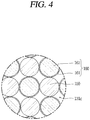
- FIG. 4 is an enlarged view illustrating a portion "A" of FIG. 3 to describe an inner structure of a heat storage member
- FIG. 5a is a sectional view illustrating another example of an inner structure of a reforming reactor according to FIG. 1
- FIG. 5b is an enlarged perspective view illustrating a portion "B" of FIG. 5a
- FIGS. 6 to 8b are longitudinal sectional views and horizontal sectional views illustrating examples of a reforming reactor according to the present invention.
- the fuel reforming device comprises a casing 10 longitudinally formed and sealed with an insulation wall therein, a combustion chamber 110 provided along a length direction of the casing 10 at the center inside the casing 10, and a burner 111 provided inside the combustion chamber 110, generating heat by combusting gas.
- the combustion chamber 110 and the burner 111 constitute a combustion part.
- a combustion gas injection inlet 11 may be provided below the casing 10 to inject a gas, which will be combusted by the burner 111, into the combustion chamber 110.
- a reactant inlet 13 for injecting a reactant toward a reforming reactor 131, which will be described later, may be formed at the top of the casing 10, and a reactant outlet 14 for discharging a reactant out by passing through each of reactors 131, 132 and 133, which will be described later, may be provided at the lower end of the casing 10.
- the burner 111 may be installed below the combustion chamber 110.
- a Bunsen burner which acquires a high temperature by combusting a combustion gas or a metal fiber which uses a combustion gas or the atmospheric air as a fuel may be used as burner 111.
- the metal fiber is more efficient than the Bunsen burner in that it may generate a high heat value due to a short flame, and has advantages in that it is easy to control load and has a wide flame range.
- the combustion chamber 110 is arranged at the center of the casing 10, and a reactor portion for generating hydrogen from a raw gas is installed outside the combustion chamber 110.
- the reactor portion generates 3H 2 +CO if a catalyst and a high temperature are applied to CH 4 and H 2 O to generate a chemical reaction. Since CO may cause the atmospheric pollution, CO is shifted to CO 2 by a chemical reaction with H 2 O.
- the reactor portion may include a reforming reactor 131 installed inside, and shift reactors 132 and 133 installed outside. That is, the reforming reactor 131 and the shift reactors 132 and 133 are formed in a cylindrical shape, whereby the reforming reactor 131 may be installed to surround the combustion chamber 110, and the shift reactors 132 and 133 may be installed to surround the reforming reactor 131.
- An exhaust path 120 which communicates with the combustion chamber 110 to constitute a discharge path of an exhaust gas generated during combustion may be formed between the reforming reactor 131 and the shift reactors 132 and 133. Therefore, the exhaust gas generated in the combustion chamber 110 may supply heat to the reforming reactor 131 while moving to the top of the casing 10, and may again supply heat to the reforming reactor 131 and the shift reactors 132 and 133 while moving to the lower side of the casing 10 by passing through a space between the reforming reactor 131 and the shift reactors 132 and 133 through the exhaust path 120.
- the reforming reactor 131 is formed in a cylindrical shape having a predetermined space 131c between an inner wall 131a and an outer wall 131b, and a catalytic material 150 for expediting a reaction of a raw gas may be filled in the space 131c.
- Ni is generally used as the catalytic material 150 in the reforming reactor 131, whereby a reaction temperature of the reforming reactor 131 is in the range of 600°C to 700°C.
- the catalytic material 150 may be formed in such a manner that a plurality of catalytic materials are attached to a plate shaped metal member (not shown), or may be formed in a shape of a plurality of balls.
- a phase change material (PCM) 160 which will be described later is formed in a shape of ball and then filled in the space 131c of the reforming reactor 131 together with the catalytic material 150, it is preferable that the catalytic material 150 is formed in a shape of ball.
- the catalytic material 150 may be formed in such a manner that a plurality of catalytic materials are attached to a plate shaped metal member as described above, whereby the catalytic materials may be filled in the space 131c of the reforming reactor 131 by rolling and the phase change material 160 according to this embodiment may be filled between the catalytic materials 150 by loading.
- the phase change material 160 is filled in the space 131c of the reforming reactor 131 (or shift reactor) and serves to provide heat required for a reforming reaction during re-actuation of the fuel reforming device after storing heat absorbed from the exhaust gas therein.
- the phase change material 160 may be referred to as a heat storage member.
- the heat storage member 160 may be formed in a shape of ball as described above.
- the entire of the heat storage member 160 may be formed of the same material, but in this case, the heat storage member 160 may be restricted with respect to a peripheral temperature. That is, if the peripheral temperature is higher than a reactor temperature, the heat storage member 160 may not be maintained as its shape during phase change, whereby loss may be generated. Therefore, it may be preferable that the heat storage member 160 according to this embodiment is formed to allow a phase change material to be built in its covering which is able to relatively withstand a high temperature.
- the heat storage member 160 may include a surface portion 161 constituting covering, and a phase change portion 162 filled in the surface portion 161, constituting a kind of a phase change material.
- the phase change portion 162 may be made of a material of which melting temperature (or phase change temperature) is lower than that of the surface portion 161 and latent heat is higher than that of the surface portion 161.
- the surface portion 161 may be made of a Cu material of which heat conductivity is excellent.
- a phase change temperature (melting temperature) of Cu is 1100°C, approximately, and its latent heat value is 200(kJ/kg), approximately.
- the phase change portion 162 may be made of Al Alloy generating phase change at a temperature similar to a reforming reaction temperature, more exactly Al-Si.
- a phase change temperature of AL-Si is 550°C
- a latent heat value of Al-Si is 200(kJ/kg), which shows a temperature zone similar to that of the reforming reactor.
- the heat storage member 160 may be tilted downwardly while moving between the catalytic materials 150. In this case, temperature gradient per position of the reforming reactor 131 is generated, whereby it may be difficult to maintain a uniform reaction temperature.
- a splitter 165 for splitting the heat storage member 160 per layer may be formed at the space 131c of the reforming reactor 131.
- one splitter 165 may be formed at the center of the space 131c, a plurality of splitters may be formed per layer up and down as the case may be.
- the plurality of splitters 165 may be formed at the position where heights of the respective layers become equal to one another, but may be formed at the position where heights of the respective layers become different from one another depending on a condition. For example, if the heat storage members 160 are formed to have the same diameter, the splitters 165 may be formed at the position where the heights of the respective layers become equal to one another, to uniformly maintain temperatures of the respective layers.
- the splitters 165 may be formed in such a manner that a height of a layer where the heat storage member having a relatively great surface area is arranged becomes low, whereas a height of a layer where the heat storage member having a relatively small surface area is arranged become high.
- the heat storage members 160 may be arranged by being distributed uniformly along a height direction without being tilted downwardly. Therefore, a temperature per position of the reforming reactor 131 may be maintained uniformly, whereby a reforming effect may be improved.
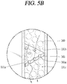
- the splitters 165 may be formed in a shape of plate having no holes to split both layers, the splitters 165 may be provided with a plurality of gas through holes 165a may be formed to allow a raw gas to actively pass therethrough as shown in FIG. 5b .
- the splitters 165 are formed in a shape of plate having no holes, it may be preferable that a width sectional area of the splitter 165 is smaller than that of the reforming reactor 131 to generate a certain interval t1 or t2 between an outer circumference of the inner wall 131a of the reforming reactor 131 and an inner circumference of the splitters 165 or between an inner circumference of the outer wall 131b of the reforming reactor 131 and an outer circumference of the splitters 165, as shown in FIGS. 6 and 7 , whereby the raw gas may pass through the splitters 165.
- the gas through holes 165a are formed in the splitters 165 as shown in FIG. 5b , it may be preferable that the gas through holes 165a are formed at a great size if possible within the range that the catalytic members 150 or the heat storage members 160 do not get out of them.
- the splitters 165 may be fixed to the inner circumference or the outer circumference of the reforming reactor 131. In this case, it may be preferable that the splitters 165 are fixed to the inner circumference or the outer circumference of the reforming reactor 131 in a zigzag shape as shown in FIG. 6 considering loading of the catalytic members 150 or the heat storage members 160.
- the splitters 165 may not be fixed to the inner wall 131a or the outer wall 131b of the reforming reactor 131. In this case, in a state that the splitters 165 are manufactured in advance as shown in FIG. 7 , the splitters 165 may be arranged at proper positions by being inserted into the center at certain intervals during loading of the catalytic members 150 or the heat storage members 160.
- splitters 165 may be formed in a ring shape to adapt to the shape of the space 131c of the reforming reactor 131, the splitters 165 may be formed in an arc shape as the case may be.
- the splitters 165 are formed of a material having a melting temperature higher than that of the heat storage members 160.
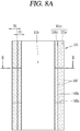
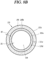
- splitters 165 may be arranged at certain intervals in a height direction (length direction) of the reforming reactor 131, in addition to horizontal splitters 165b, a vertical splitter 165c may further be provided between the inner wall 131a and the outer wall 131b of the reforming reactor 131 as shown in FIG. 8a , whereby the space 131c may be split into the inner circumference and the outer circumference in a horizontal direction.
- the heat storage members 160 arranged in an inner circumference space 131d and an outer circumference space 131e may be loaded at the same specification as much as the same amount, the heat storage members 160 may be loaded in the inner circumference space 131d and the outer circumference space 131e at different specifications as much as different amount.
- a width D1 of the inner circumference space 131d may be smaller than a width D2 of the outer circumference space 131e. That is, considering that the exhaust gas first contacts the inner circumference space 131d, the inner circumference space 131d may be arranged in such a manner that an entire surface area of the heat storage members 160 arranged in the outer circumference space 131e is greater than an entire surface area of the heat storage members 160 arranged in the inner circumference space 131d based on the same circumference length.
- FIGS. 9 and 10 are brief views illustrating a heat storage process in a fuel reforming device according to the present invention.
- the temperature controller may include temperature sensors 171a to 171c for detecting a temperature of the reforming reactor 131, and a controller 172 for controlling an operation of the burner 111 by comparing the temperature detected from the temperature sensors 171a to 171c with a set temperature, as shown in FIGS. 2 and 9 .
- a plurality of the temperature sensors 171a to 171c may be arranged on the inner circumference or the outer circumference of the reforming reactor 131 in a length direction (up and down) at proper intervals along a moving direction of the exhaust gas.
- the temperature sensors 171a to 171c are arranged on the inner circumference of the reforming reactor 131 at three stages.
- the controller 172 may include an input module 172a electrically connected with the plurality of temperature, receiving detection temperatures from the temperature sensors 171a to 171c, a determination module 172b determining whether to operate the burner 111 by comparing the detection temperatures T1, T2 and T3 input to the input module 172a with a set temperature Ts, and an output module 172c transmitting an operation signal or a stop signal to the burner 111 in accordance with the result determined by the determination module 172b.
- the determination module 172b may transmit the operation signal to the output module 172c to operate the burner 111 if the detection temperatures T1, T2 and T3 are lower than the set temperature Ts, whereas the determination module 172b may transmit the stop signal to the output module 172c to maintain a stopped state of the burner 111 if the detection temperatures T1, T2 and T3 are higher than the set temperature Ts.
- a specific temperature that is, a phase change temperature of the phase change portion 162 may be defined as the set temperature Ts, or a temperature greater than or smaller than the phase change temperature within a certain range may be defined as the set temperature Ts.
- a temperature obtained by adding or subtracting a specific temperature to or from the phase change temperature may be defined as the set temperature Ts.
- a temperature detected from any one of the temperature sensors may be defined as the detection temperature or an average temperature of temperatures detected from the plurality of temperature sensors may be defined as the detection temperature.
- the temperature sensors 171a to 171c of the respective stages detect a temperature of the reforming reactor 131 per stage, and the lowest detection temperature of the temperature sensors 171a to 171c may be compared with the set temperature to determine whether the burner should be operated.
- the set temperature Ts may be a temperature obtained by adding a tolerance temperature (10°C in the drawing) to the phase change temperature of the heat storage member 160. Therefore, the detection temperatures T1 to T3 are compared with the set temperature Ts, and as a result, if the detection temperature is higher than the set temperature, it is determined that latent heat through phase change of the heat storage member 160 may be used even by the current temperature of the reforming reactor, whereby the burner 111 may be maintained at a stopped state or its heating power may be lowered. On the other hand, if the detection temperature is lower than the set temperature, since the current heat storage member 160 cannot use latent heat, the burner 111 may be operated or its heating power may be enhanced, whereby the phase change portion of the heat storage member 160 may generate phase change.
- the burner may be operated per fixed time using a timer without a separate temperature sensor, whereby the heat storage member may maintain a phase change temperature.
- the reforming reactor may be maintained at a proper temperature even in a state that the operation of the fuel reforming device or the fuel cell system that includes the fuel reforming device is stopped.
- the fuel reforming device that includes the reforming reactor may quickly reach the operation temperature by using latent heat of the heat storage member during re-actuation of the fuel reforming device or the fuel cell system that includes the fuel reforming device.
- the possibility of hydrogen generation in the fuel reforming device may be increased, whereby efficiency of the fuel cell system may be increased.
Landscapes
- Chemical & Material Sciences (AREA)
- Chemical Kinetics & Catalysis (AREA)
- Organic Chemistry (AREA)
- Engineering & Computer Science (AREA)
- Life Sciences & Earth Sciences (AREA)
- Combustion & Propulsion (AREA)
- Manufacturing & Machinery (AREA)
- Sustainable Development (AREA)
- Sustainable Energy (AREA)
- Electrochemistry (AREA)
- General Chemical & Material Sciences (AREA)
- Inorganic Chemistry (AREA)
- General Health & Medical Sciences (AREA)
- Health & Medical Sciences (AREA)
- Hydrogen, Water And Hydrids (AREA)
- Fuel Cell (AREA)
Abstract
Description
- The present invention relates to a fuel reforming device that generates hydrogen by reforming a hydrocarbon based raw material.
- Generally, a fuel reforming device is a kind of a reformer that generates hydrogen by reforming a raw gas such as LNG and LPG, and is widely known as steam reforming device.
- Steam reforming device includes a steam reformer for shifting a raw gas to hydrogen, a shift reactor [high temperature shift reactor (HTS) and low temperature shift reactor (LTS)] for shifting carbon monoxide (CO) generated with hydrogen to carbon dioxide (CO2) to lower concentration of the carbon monoxide, and a burner for supplying calories.
- For example, if LNG of which main component is CH4 is a raw gas, LNG is reacted with steam in the steam reformer, whereby hydrogen and carbon dioxide are generated. However, if carbon monoxide flows into a fuel cell stack, the stack is contaminated by carbon monoxide, whereby performance of the stack may be degraded seriously. Therefore, carbon monoxide generated through the steam reformer is shifted to carbon dioxide by using the HTS and the LTS.
- In this case, an operation temperature in the steam reformer is different depending on a type of a catalyst. If Ni is used as a catalyst, the operation temperature is generally in the range of 600°C to 700°C, and this reaction is an endothermic reaction and calories required for this endothermic reaction are supplied using a burner. An operation temperature in the shift reactor is also different depending on the type of the catalyst, wherein the operation temperature is generally in the range of 300°C to 420°C in case of a high temperature shift reactor based on Cu-Zn, and is generally in the range of 235°C to 300°C in case of a low temperature shift reactor based on Fe-Cr. This shift reaction is an exothermic reaction and radiates heat during reaction.
- Meanwhile, a fuel processing device of the conventional art may be categorized into a horizontal (or radial) fuel processing device and a longitudinal (or vertical) fuel processing device depending on arrangement of a steam reformer and a shift reactor.
- In the horizontal fuel processing device, a steam reformer is arranged inside while a shift reactor is arranged outside. A combustion chamber provided with a burner is arranged inside the steam reformer, that is, at the innermost of the fuel processing device. In this horizontal fuel processing device, a combustion gas generated during combustion supplies heat to the steam reformer by upwardly passing through a path between the steam reformer and the combustion chamber, and then is discharged out. At this time, a raw gas downwardly moves by passing through the steam reformer and then is reformed while upwardly moving by passing through the shift reactor, whereby the raw gas is supplied to a fuel cell stack.
- In the aforementioned horizontal fuel processing device of the conventional art, when the steam reformer is re-actuated after being stopped, it needs much time to reach an operation temperature in view of property of the steam reformer operated at high temperature. Therefore, problems occur in that the steam reformer is not re-actuated quickly and a system operation rate is degraded. Particularly, since a temperature attenuation speed of the steam reforming (SR) which performs an endothermic reaction at a relatively high temperature is faster than that of the shift reactor during stop, much more time is required to reach the operation temperature during re-actuation.
- Also, a temperature of an exhaust gas generated from the burner during combustion is reduced after heat exchange, whereby a problem occurs in that a temperature gradient is increased at the end of the steam reformer and thus reaction deviation per position occurs seriously.
- Therefore, an object of the present invention is to substantially obviate one or more problems due to limitations and disadvantages of the related art.
- Another object of the present invention is to provide a fuel reforming device that may reduce time required to reach an operation temperature during re-actuation of a steam reformer (reforming reactor) to increase a system operation rate by quickly re-actuating the steam reformer.
- Other object of the present invention is to provide a fuel reforming device that increase a reforming effect by lowering a temperature gradient per position of a reactor.
- The object is solved by the features of the independent claims. Preferred embodiments are given in the dependent claims.
- To achieve these and other advantages and in accordance with the purpose of the invention, as embodied and broadly described herein, a fuel reforming device comprises a combustion part where a burner is installed; an exhaust part through which an exhaust gas generated from the combustion part is circulated; and a reactor provided near the combustion part and/or the exhaust part, generating hydrogen from a raw material by absorbing heat from the exhaust gas passing through the combustion part and the exhaust part, wherein the reactor is provided with a heat storage member that absorbs heat during operation of the combustion part and stores the absorbed heat therein to provide heat required by the reactor to the reactor.
- In this case, the heat storage member may be provided with a phase change portion constituting a phase change material inside a surface portion, the phase change portion being made of a material having a melting temperature lower than that of the surface portion and/or latent heat higher than that of the surface portion.
- The surface portion may be made of Cu, and/or the phase change portion may be made of Al alloy.
- The fuel reforming device may further comprise a temperature controller for maintaining a temperature of the heat storage member.
- The temperature controller may include at least one or more temperature sensors installed along a moving direction of the exhaust gas, detecting a temperature of the reactor.
- The temperature controller may include a controller controlling an operation of the burner by comparing temperatures detected by the temperature sensors with the melting temperature of the heat storage member.
- The controller may control the burner to allow the lowest one of the temperatures detected by the temperature sensors to be maintained to be higher than the melting temperature of the heat storage member.
- The heat storage member may be formed in a shape of a plurality of balls filled in the reactor.
- The reactor may be provided with a splitter for splitting the reactor into two or more spaces, and the heat storage member may be arranged at the two or more spaces of the reactor.
- Any one of an inner circumference or an outer circumference of the splitter may be fixed to an inner circumference or an outer circumference of the reactor.
- The splitter may include a plurality of splitters arranged at certain intervals along a length direction of the reactor, and adjacent splitters of the plurality of splitters are fixed to each other in a zigzag shape.
- The inner circumference and the outer circumference of the splitter may be spaced apart from the inner circumference and the outer circumference of the reactor.
- The splitter may be arranged between the inner circumference and the outer circumference of the reactor along a length direction to allow the reactor to be split into an inner circumference space and an outer circumference space.
- The splitter may be provided with a plurality of gas through holes.
- The splitter may be made of a material of which melting temperature is higher than that of the heat storage member.
- The reactor may be filled with a catalytic member together with the heat storage member.
- In another aspect of the present invention, to achieve these and other advantages and in accordance with the purpose of the invention, a fuel reforming device comprises a combustion part where a burner is installed; an exhaust part through which an exhaust gas generated from the combustion part is circulated; a reactor provided near the combustion part or the exhaust part, generating hydrogen from a raw material by absorbing heat from the exhaust gas passing through the combustion part and the exhaust part; a heat storage member provided in the reactor, absorbing heat during operation of the combustion part and storing the absorbed heat therein to provide heat required for the reactor to the reactor; a plurality of temperature sensors installed in the reactor along a moving direction of the exhaust gas, detecting a temperature of the reactor; and a controller controlling an operation of the burner by comparing temperatures detected by the temperature sensors with a melting temperature of the heat storage member.
- In the fuel reforming device according to the present invention, a reforming reactor may be maintained at a proper temperature even in a state that an operation of the fuel reforming device or a fuel cell system that includes the fuel reforming device is stopped. As a result, the fuel reforming device that includes the reforming reactor may quickly reach the operation temperature by using latent heat of the heat storage member during re-actuation of the fuel reforming device or the fuel cell system that includes the fuel reforming device.
- Also, in this case, the possibility of hydrogen generation in the fuel reforming device may be increased, whereby efficiency of the fuel cell system may be increased.
- Further scope of applicability of the present application will become more apparent from the detailed description given hereinafter. However, it should be understood that the detailed description and specific examples, while indicating preferred embodiments of the invention, are given by way of illustration only, since various changes and modifications within the scope of the invention will become apparent to those skilled in the art from the detailed description.
- The accompanying drawings, which are included to provide a further understanding of the invention and are incorporated in and constitute a part of this specification, illustrate exemplary embodiments and together with the description serve to explain the principles of the invention.
- In the drawings:
-
FIG. 1 is a perspective view illustrating a broken section of a fuel reforming device according to one embodiment of the present invention; -
FIG. 2 is a longitudinal sectional view illustrating a reforming reactor of a fuel reforming device according toFIG. 1 ; -
FIG. 3 is a sectional view taken along line "I-I" ofFIG. 2 ; -
FIG. 4 is an enlarged view illustrating a portion "A" ofFIG. 3 to describe an inner structure of a heat storage member; -
FIG. 5a is a sectional view illustrating another example of an inner structure of a reforming reactor according toFIG. 1 ; -
FIG. 5b is an enlarged perspective view illustrating a portion "B" ofFIG. 5a ; -
FIGS. 6 to 8b are longitudinal sectional views and horizontal sectional views illustrating examples of a reforming reactor according to the present invention; -
FIG. 9 is a block diagram illustrating a temperature controller of the fuel reforming device according to the present invention; and -
FIG. 10 is brief views illustrating a heat storage process in a fuel reforming device according to the present invention. - Hereinafter, a fuel reforming device according to one embodiment of the present invention will be described in detail with reference to the accompanying drawings.
-
FIG. 1 is a perspective view illustrating a broken section of a fuel reforming device according to one embodiment of the present invention,FIG. 2 is a longitudinal sectional view illustrating a reforming reactor of a fuel reforming device according toFIG. 1 ,FIG. 3 is a sectional view taken along line "I-I" ofFIG. 2 ,FIG. 4 is an enlarged view illustrating a portion "A" ofFIG. 3 to describe an inner structure of a heat storage member,FIG. 5a is a sectional view illustrating another example of an inner structure of a reforming reactor according toFIG. 1 ,FIG. 5b is an enlarged perspective view illustrating a portion "B" ofFIG. 5a , andFIGS. 6 to 8b are longitudinal sectional views and horizontal sectional views illustrating examples of a reforming reactor according to the present invention. - Referring to
FIGS. 1 to 3 , the fuel reforming device according to the embodiment of the present invention comprises acasing 10 longitudinally formed and sealed with an insulation wall therein, acombustion chamber 110 provided along a length direction of thecasing 10 at the center inside thecasing 10, and aburner 111 provided inside thecombustion chamber 110, generating heat by combusting gas. Thecombustion chamber 110 and theburner 111 constitute a combustion part. - A combustion
gas injection inlet 11 may be provided below thecasing 10 to inject a gas, which will be combusted by theburner 111, into thecombustion chamber 110. Areactant inlet 13 for injecting a reactant toward a reformingreactor 131, which will be described later, may be formed at the top of thecasing 10, and areactant outlet 14 for discharging a reactant out by passing through each ofreactors casing 10. - The
burner 111 may be installed below thecombustion chamber 110. A Bunsen burner which acquires a high temperature by combusting a combustion gas or a metal fiber which uses a combustion gas or the atmospheric air as a fuel may be used asburner 111. In this case, the metal fiber is more efficient than the Bunsen burner in that it may generate a high heat value due to a short flame, and has advantages in that it is easy to control load and has a wide flame range. - The
combustion chamber 110 is arranged at the center of thecasing 10, and a reactor portion for generating hydrogen from a raw gas is installed outside thecombustion chamber 110. The reactor portion generates 3H2+CO if a catalyst and a high temperature are applied to CH4 and H2O to generate a chemical reaction. Since CO may cause the atmospheric pollution, CO is shifted to CO2 by a chemical reaction with H2O. - The reactor portion may include a reforming
reactor 131 installed inside, and shiftreactors reactor 131 and theshift reactors reactor 131 may be installed to surround thecombustion chamber 110, and theshift reactors reactor 131. - An
exhaust path 120 which communicates with thecombustion chamber 110 to constitute a discharge path of an exhaust gas generated during combustion may be formed between the reformingreactor 131 and theshift reactors combustion chamber 110 may supply heat to the reformingreactor 131 while moving to the top of thecasing 10, and may again supply heat to the reformingreactor 131 and theshift reactors casing 10 by passing through a space between the reformingreactor 131 and theshift reactors exhaust path 120. - The reforming
reactor 131 is formed in a cylindrical shape having apredetermined space 131c between aninner wall 131a and anouter wall 131b, and acatalytic material 150 for expediting a reaction of a raw gas may be filled in thespace 131c. Ni is generally used as thecatalytic material 150 in the reformingreactor 131, whereby a reaction temperature of the reformingreactor 131 is in the range of 600°C to 700°C. - In this case, the
catalytic material 150 may be formed in such a manner that a plurality of catalytic materials are attached to a plate shaped metal member (not shown), or may be formed in a shape of a plurality of balls. In this embodiment, since a phase change material (PCM) 160 which will be described later is formed in a shape of ball and then filled in thespace 131c of the reformingreactor 131 together with thecatalytic material 150, it is preferable that thecatalytic material 150 is formed in a shape of ball. However, as the case may be, thecatalytic material 150 may be formed in such a manner that a plurality of catalytic materials are attached to a plate shaped metal member as described above, whereby the catalytic materials may be filled in thespace 131c of the reformingreactor 131 by rolling and thephase change material 160 according to this embodiment may be filled between thecatalytic materials 150 by loading. - The
phase change material 160 is filled in thespace 131c of the reforming reactor 131 (or shift reactor) and serves to provide heat required for a reforming reaction during re-actuation of the fuel reforming device after storing heat absorbed from the exhaust gas therein. Hereinafter, thephase change material 160 may be referred to as a heat storage member. - The
heat storage member 160 may be formed in a shape of ball as described above. - Also, the entire of the
heat storage member 160 may be formed of the same material, but in this case, theheat storage member 160 may be restricted with respect to a peripheral temperature. That is, if the peripheral temperature is higher than a reactor temperature, theheat storage member 160 may not be maintained as its shape during phase change, whereby loss may be generated. Therefore, it may be preferable that theheat storage member 160 according to this embodiment is formed to allow a phase change material to be built in its covering which is able to relatively withstand a high temperature. - For example, as shown in
FIG. 4 , theheat storage member 160 according to this embodiment may include asurface portion 161 constituting covering, and aphase change portion 162 filled in thesurface portion 161, constituting a kind of a phase change material. - The
phase change portion 162 may be made of a material of which melting temperature (or phase change temperature) is lower than that of thesurface portion 161 and latent heat is higher than that of thesurface portion 161. - In this case, the
surface portion 161 may be made of a Cu material of which heat conductivity is excellent. For reference, a phase change temperature (melting temperature) of Cu is 1100°C, approximately, and its latent heat value is 200(kJ/kg), approximately. - Also, the
phase change portion 162 may be made of Al Alloy generating phase change at a temperature similar to a reforming reaction temperature, more exactly Al-Si. For reference, a phase change temperature of AL-Si is 550°C, and a latent heat value of Al-Si is 200(kJ/kg), which shows a temperature zone similar to that of the reforming reactor. - Meanwhile, if the
heat storage member 160 is formed in a shape of ball and filled in thespace 131c of the reforming reactor, theheat storage member 160 may be tilted downwardly while moving between thecatalytic materials 150. In this case, temperature gradient per position of the reformingreactor 131 is generated, whereby it may be difficult to maintain a uniform reaction temperature. - Considering this, in this embodiment as shown in
FIG. 5a , asplitter 165 for splitting theheat storage member 160 per layer may be formed at thespace 131c of the reformingreactor 131. Although onesplitter 165 may be formed at the center of thespace 131c, a plurality of splitters may be formed per layer up and down as the case may be. - Also, the plurality of
splitters 165 may be formed at the position where heights of the respective layers become equal to one another, but may be formed at the position where heights of the respective layers become different from one another depending on a condition. For example, if theheat storage members 160 are formed to have the same diameter, thesplitters 165 may be formed at the position where the heights of the respective layers become equal to one another, to uniformly maintain temperatures of the respective layers. However, if theheat storage members 160 are formed to have different diameters (surface areas), thesplitters 165 may be formed in such a manner that a height of a layer where the heat storage member having a relatively great surface area is arranged becomes low, whereas a height of a layer where the heat storage member having a relatively small surface area is arranged become high. - As a result, even though the ball shaped
heat storage members 160 move between the plurality of catalytic members formed in a shape of ball or a shape similar to the ball, theheat storage members 160 may be arranged by being distributed uniformly along a height direction without being tilted downwardly. Therefore, a temperature per position of the reformingreactor 131 may be maintained uniformly, whereby a reforming effect may be improved. - Also, although the
splitters 165 may be formed in a shape of plate having no holes to split both layers, thesplitters 165 may be provided with a plurality of gas throughholes 165a may be formed to allow a raw gas to actively pass therethrough as shown inFIG. 5b . - In this case, if the
splitters 165 are formed in a shape of plate having no holes, it may be preferable that a width sectional area of thesplitter 165 is smaller than that of the reformingreactor 131 to generate a certain interval t1 or t2 between an outer circumference of theinner wall 131a of the reformingreactor 131 and an inner circumference of thesplitters 165 or between an inner circumference of theouter wall 131b of the reformingreactor 131 and an outer circumference of thesplitters 165, as shown inFIGS. 6 and7 , whereby the raw gas may pass through thesplitters 165. If the gas throughholes 165a are formed in thesplitters 165 as shown inFIG. 5b , it may be preferable that the gas throughholes 165a are formed at a great size if possible within the range that thecatalytic members 150 or theheat storage members 160 do not get out of them. - Also, the
splitters 165 may be fixed to the inner circumference or the outer circumference of the reformingreactor 131. In this case, it may be preferable that thesplitters 165 are fixed to the inner circumference or the outer circumference of the reformingreactor 131 in a zigzag shape as shown inFIG. 6 considering loading of thecatalytic members 150 or theheat storage members 160. - However, the
splitters 165 may not be fixed to theinner wall 131a or theouter wall 131b of the reformingreactor 131. In this case, in a state that thesplitters 165 are manufactured in advance as shown inFIG. 7 , thesplitters 165 may be arranged at proper positions by being inserted into the center at certain intervals during loading of thecatalytic members 150 or theheat storage members 160. - Also, although the
splitters 165 may be formed in a ring shape to adapt to the shape of thespace 131c of the reformingreactor 131, thesplitters 165 may be formed in an arc shape as the case may be. - Also, in view of stability, it may be preferable that the
splitters 165 are formed of a material having a melting temperature higher than that of theheat storage members 160. - Also, although the
splitters 165 may be arranged at certain intervals in a height direction (length direction) of the reformingreactor 131, in addition tohorizontal splitters 165b, avertical splitter 165c may further be provided between theinner wall 131a and theouter wall 131b of the reformingreactor 131 as shown inFIG. 8a , whereby thespace 131c may be split into the inner circumference and the outer circumference in a horizontal direction. If thevertical splitter 165c is provided, although theheat storage members 160 arranged in aninner circumference space 131d and anouter circumference space 131e may be loaded at the same specification as much as the same amount, theheat storage members 160 may be loaded in theinner circumference space 131d and theouter circumference space 131e at different specifications as much as different amount. - For example, as shown in
FIGS. 8a and8b , a width D1 of theinner circumference space 131d may be smaller than a width D2 of theouter circumference space 131e. That is, considering that the exhaust gas first contacts theinner circumference space 131d, theinner circumference space 131d may be arranged in such a manner that an entire surface area of theheat storage members 160 arranged in theouter circumference space 131e is greater than an entire surface area of theheat storage members 160 arranged in theinner circumference space 131d based on the same circumference length. As a result, even though the temperature of theouter circumference space 131e is increased more slowly than the temperature of theinner circumference space 131d during re-actuation of the reformingreactor 131, since the surface area of theheat storage members 160 arranged in theouter circumference space 131e is greater than that of theheat storage members 160 arranged in theinner circumference space 131d, more heat may be supplied from theheat storage member 160 to theouter circumference space 131e, whereby theouter circumference space 131e may reach an operation temperature similarly to theinner circumference space 131d. - Meanwhile, in this embodiment, a temperature controller for appropriately supplying heat required for phase change of the heat storage members may further be provided to use latent heat of the heat storage members.
FIGS. 9 and 10 are brief views illustrating a heat storage process in a fuel reforming device according to the present invention. - For example, the temperature controller according to this embodiment may include
temperature sensors 171a to 171c for detecting a temperature of the reformingreactor 131, and acontroller 172 for controlling an operation of theburner 111 by comparing the temperature detected from thetemperature sensors 171a to 171c with a set temperature, as shown inFIGS. 2 and9 . - A plurality of the
temperature sensors 171a to 171c may be arranged on the inner circumference or the outer circumference of the reformingreactor 131 in a length direction (up and down) at proper intervals along a moving direction of the exhaust gas. For reference, inFIG. 2 , thetemperature sensors 171a to 171c are arranged on the inner circumference of the reformingreactor 131 at three stages. - The
controller 172 may include an input module 172a electrically connected with the plurality of temperature, receiving detection temperatures from thetemperature sensors 171a to 171c, a determination module 172b determining whether to operate theburner 111 by comparing the detection temperatures T1, T2 and T3 input to the input module 172a with a set temperature Ts, and an output module 172c transmitting an operation signal or a stop signal to theburner 111 in accordance with the result determined by the determination module 172b. - The determination module 172b may transmit the operation signal to the output module 172c to operate the
burner 111 if the detection temperatures T1, T2 and T3 are lower than the set temperature Ts, whereas the determination module 172b may transmit the stop signal to the output module 172c to maintain a stopped state of theburner 111 if the detection temperatures T1, T2 and T3 are higher than the set temperature Ts. - In this case, a specific temperature, that is, a phase change temperature of the
phase change portion 162 may be defined as the set temperature Ts, or a temperature greater than or smaller than the phase change temperature within a certain range may be defined as the set temperature Ts. Also, a temperature obtained by adding or subtracting a specific temperature to or from the phase change temperature may be defined as the set temperature Ts. - Also, if the plurality of
temperature sensors 171a to 171c are provided, that is, the plurality of detection temperatures T1 to T3 are provided, a temperature detected from any one of the temperature sensors may be defined as the detection temperature or an average temperature of temperatures detected from the plurality of temperature sensors may be defined as the detection temperature. - For example, if the three
temperature sensors 171a to 171c are provided at a lower stage, a middle stage and an upper stage of the reforming reactor, thetemperature sensors 171a to 171c of the respective stages detect a temperature of the reformingreactor 131 per stage, and the lowest detection temperature of thetemperature sensors 171a to 171c may be compared with the set temperature to determine whether the burner should be operated. - In this case, the set temperature Ts may be a temperature obtained by adding a tolerance temperature (10°C in the drawing) to the phase change temperature of the
heat storage member 160. Therefore, the detection temperatures T1 to T3 are compared with the set temperature Ts, and as a result, if the detection temperature is higher than the set temperature, it is determined that latent heat through phase change of theheat storage member 160 may be used even by the current temperature of the reforming reactor, whereby theburner 111 may be maintained at a stopped state or its heating power may be lowered. On the other hand, if the detection temperature is lower than the set temperature, since the currentheat storage member 160 cannot use latent heat, theburner 111 may be operated or its heating power may be enhanced, whereby the phase change portion of theheat storage member 160 may generate phase change. - Meanwhile, in the aforementioned embodiment, after the temperature of the reforming reactor is detected in real time using the temperature sensor, it is determined whether to operate the burner in accordance with the detected result. However, in another embodiment, the burner may be operated per fixed time using a timer without a separate temperature sensor, whereby the heat storage member may maintain a phase change temperature.
- Therefore, the reforming reactor may be maintained at a proper temperature even in a state that the operation of the fuel reforming device or the fuel cell system that includes the fuel reforming device is stopped. As a result, the fuel reforming device that includes the reforming reactor may quickly reach the operation temperature by using latent heat of the heat storage member during re-actuation of the fuel reforming device or the fuel cell system that includes the fuel reforming device. In this case, the possibility of hydrogen generation in the fuel reforming device may be increased, whereby efficiency of the fuel cell system may be increased.
- The foregoing embodiments and advantages are merely exemplary and are not to be considered as limiting the present disclosure. The present teachings can be readily applied to other types of apparatuses. This description is intended to be illustrative, and not to limit the scope of the claims. Many alternatives, modifications, and variations will be apparent to those skilled in the art. The features, structures, methods, and other characteristics of the exemplary embodiments described herein may be combined in various ways to obtain additional and/or alternative exemplary embodiments.
- As the present features may be embodied in several forms without departing from the characteristics thereof, it should also be understood that the above-described embodiments are not limited by any of the details of the foregoing description, unless otherwise specified, but rather should be considered broadly within its scope as defined in the appended claims, and therefore all changes and modifications that fall within the metes and bounds of the claims, or equivalents of such metes and bounds are therefore intended to be embraced by the appended claims.
Claims (15)
- A fuel reforming device comprising:a combustion part (110, 11),a burner (111) installed in the combustion part (110, 11);an exhaust part (120) through which an exhaust gas generated from the combustion part (110, 11) is discharged; anda reactor (131, 132, 133) provided near the combustion part (110, 11) or the exhaust part (120), generating hydrogen from a raw material by absorbing heat from the exhaust gas passing through the combustion part (110, 11) or the exhaust part (120),wherein the reactor (131, 132, 133) is provided with a heat storage member (160) that absorbs heat during operation of the combustion part (110, 11) and stores the absorbed heat therein to provide heat required by the reactor to the reactor (131, 132, 133).
- The fuel reforming device of claim 1, wherein the heat storage member (160) is provided with a phase change portion (162) constituting a phase change material inside a surface portion (161), the phase change portion (162) being made of a material having a melting temperature lower than that of the surface portion (161) and/or latent heat higher than that of the surface portion (161).
- The fuel reforming device of claim 2, wherein the surface portion (161) is made of Cu, and/or the phase change portion (162) is made of Al alloy.
- The fuel reforming device of any one of claims 1 to 3, further comprising a temperature controller for maintaining a temperature of the heat storage member (160).
- The fuel reforming device of claim 4, wherein the temperature controller includes:at least one or more temperature sensors (171a ∼ 171c) installed along a moving direction of the exhaust gas, detecting a temperature of the reactor (131, 132, 133); anda controller (172) controlling an operation of the burner (111) by comparing temperatures detected by the temperature sensors (171a ∼ 171c) with the melting temperature of the heat storage member (160).
- The fuel reforming device of claim 5, wherein the controller (172) is adapted to control the burner (111) to allow the lowest one of the temperatures detected by the temperature sensors (171a ∼ 171c) to be maintained or to be higher than the melting temperature of the heat storage member (160).
- The fuel reforming device of any one of claims 1 to 6, wherein the heat storage member (160) is formed in a shape of a plurality of balls filled in the reactor (131, 132, 133).
- The fuel reforming device of any one of claims 1-7, wherein the reactor (131) is provided with at least one splitter (165) for splitting the reactor (131) into two or more spaces, and the heat storage member (160) is arranged at the two or more spaces of the reactor.
- The fuel reforming device of claim 8, wherein any one of an inner circumference or an outer circumference of the at least one splitter (165) is fixed to an inner circumference or an outer circumference of the reactor (131).
- The fuel reforming device of claim 8 or 9, wherein the splitter (165) includes a plurality of splitters arranged at certain intervals along a length direction of the reactor (131), and adjacent splitters (165) of the plurality of splitters are fixed to each other in a zigzag shape.
- The fuel reforming device of claim 8, wherein an inner circumference and an outer circumference of the splitter (165) are spaced apart from an inner circumference and an outer circumference of the reactor (131).
- The fuel reforming device of any one of claims 8-10 or 11, wherein the splitter (165) is arranged between an inner circumference and an outer circumference of the reactor (131) along a length direction to allow the reactor (131) to be split into an inner circumference space (131d) and an outer circumference space (131e).
- The fuel reforming device of any one of claims 8-12, wherein the splitter (165) is provided with a plurality of gas through holes (165a).
- The fuel reforming device of any one of claims 8-13, wherein the splitter (165) is made of a material of which melting temperature is higher than that of the heat storage member (160).
- The fuel reforming device of any one of claims 1 to 14, wherein the reactor (131) is filled with a catalytic member together with the heat storage member (160).
Applications Claiming Priority (1)
| Application Number | Priority Date | Filing Date | Title |
|---|---|---|---|
| KR1020160137661A KR20180044059A (en) | 2016-10-21 | 2016-10-21 | Fuel reforming divice |
Publications (2)
| Publication Number | Publication Date |
|---|---|
| EP3311911A1 true EP3311911A1 (en) | 2018-04-25 |
| EP3311911B1 EP3311911B1 (en) | 2020-03-11 |
Family
ID=59923214
Family Applications (1)
| Application Number | Title | Priority Date | Filing Date |
|---|---|---|---|
| EP17188385.3A Active EP3311911B1 (en) | 2016-10-21 | 2017-08-29 | Fuel reforming device |
Country Status (4)
| Country | Link |
|---|---|
| US (1) | US10418653B2 (en) |
| EP (1) | EP3311911B1 (en) |
| JP (1) | JP6541729B2 (en) |
| KR (1) | KR20180044059A (en) |
Cited By (2)
| Publication number | Priority date | Publication date | Assignee | Title |
|---|---|---|---|---|
| CN109880596A (en) * | 2019-02-12 | 2019-06-14 | 武汉博茗低碳产业股份有限公司 | A kind of gradient PCM storage unit and preparation method thereof |
| WO2020103995A1 (en) | 2018-11-20 | 2020-05-28 | Blue World Technologies Holding ApS | Fuel cell system, its use and method of its operation |
Families Citing this family (3)
| Publication number | Priority date | Publication date | Assignee | Title |
|---|---|---|---|---|
| KR101866500B1 (en) * | 2016-11-14 | 2018-07-04 | 한국에너지기술연구원 | Hydrogen production rector including carbon monoxide removing unit |
| CN111928239A (en) * | 2020-08-11 | 2020-11-13 | 重庆大学 | Combustion device combining phase-change molten salt and porous medium |
| CN114400354B (en) * | 2022-03-25 | 2022-07-01 | 清华大学 | Fuel pretreatment device and fuel cell system |
Citations (1)
| Publication number | Priority date | Publication date | Assignee | Title |
|---|---|---|---|---|
| WO2014063191A1 (en) * | 2012-10-26 | 2014-05-01 | Newcastle Innovation Limited | Alloys with inverse microstructures |
Family Cites Families (8)
| Publication number | Priority date | Publication date | Assignee | Title |
|---|---|---|---|---|
| JPS5953201B2 (en) * | 1979-12-18 | 1984-12-24 | 松下電器産業株式会社 | Hydrogen gas purification method |
| JPH09306533A (en) | 1996-05-17 | 1997-11-28 | Toyota Motor Corp | Heat exchanger and reformer |
| JP3809906B2 (en) * | 2002-08-09 | 2006-08-16 | 友宏 秋山 | Reaction accelerator, reactor and reaction promotion method |
| WO2006006479A1 (en) * | 2004-07-12 | 2006-01-19 | Sumitomo Seika Chemicals Co., Ltd. | Hydrogen production system and reforming apparatus |
| JP4202993B2 (en) * | 2004-09-30 | 2008-12-24 | 株式会社東芝 | Fuel reforming system and fuel cell system |
| JP4815140B2 (en) * | 2005-03-29 | 2011-11-16 | 出光興産株式会社 | Reformer and fuel cell system |
| JP4617966B2 (en) * | 2005-03-31 | 2011-01-26 | パナソニック株式会社 | Hydrogen generator |
| EP2671843B1 (en) * | 2011-11-16 | 2019-01-23 | Panasonic Intellectual Property Management Co., Ltd. | Fuel processor |
-
2016
- 2016-10-21 KR KR1020160137661A patent/KR20180044059A/en not_active Ceased
-
2017
- 2017-08-09 JP JP2017153801A patent/JP6541729B2/en not_active Expired - Fee Related
- 2017-08-29 EP EP17188385.3A patent/EP3311911B1/en active Active
- 2017-09-21 US US15/711,053 patent/US10418653B2/en active Active
Patent Citations (1)
| Publication number | Priority date | Publication date | Assignee | Title |
|---|---|---|---|---|
| WO2014063191A1 (en) * | 2012-10-26 | 2014-05-01 | Newcastle Innovation Limited | Alloys with inverse microstructures |
Non-Patent Citations (1)
| Title |
|---|
| NOBUHIRO MARUOKA ET AL: "Development of PCM Reactor for Methane Steam Reforming", ISIJ INTERNATIONAL, vol. 50, no. 9, 30 April 2010 (2010-04-30), JP, pages 1305 - 1310, XP055449066, ISSN: 0915-1559, DOI: 10.2355/isijinternational.50.1305 * |
Cited By (3)
| Publication number | Priority date | Publication date | Assignee | Title |
|---|---|---|---|---|
| WO2020103995A1 (en) | 2018-11-20 | 2020-05-28 | Blue World Technologies Holding ApS | Fuel cell system, its use and method of its operation |
| US12021277B2 (en) | 2018-11-20 | 2024-06-25 | Blue World Technologies Holding ApS | Fuel cell system, and method of its operation |
| CN109880596A (en) * | 2019-02-12 | 2019-06-14 | 武汉博茗低碳产业股份有限公司 | A kind of gradient PCM storage unit and preparation method thereof |
Also Published As
| Publication number | Publication date |
|---|---|
| US20180115004A1 (en) | 2018-04-26 |
| US10418653B2 (en) | 2019-09-17 |
| JP6541729B2 (en) | 2019-07-10 |
| KR20180044059A (en) | 2018-05-02 |
| JP2018065736A (en) | 2018-04-26 |
| EP3311911B1 (en) | 2020-03-11 |
Similar Documents
| Publication | Publication Date | Title |
|---|---|---|
| EP3311911A1 (en) | Fuel reforming device | |
| EP2810328B1 (en) | Fuel cell module | |
| US7223296B2 (en) | Hydrogen generation system and fuel cell system having the same | |
| US10556190B2 (en) | Apparatus for generating water vapor with heat-retaining medium and fuel cell system having the apparatus | |
| EP2407224B1 (en) | Catalytic Combustor for a Reformer for a Fuel Cell | |
| KR20170118817A (en) | Centrifugal blower system with internal gas mixture | |
| KR102093864B1 (en) | Catalytic Burner Arrangement | |
| JP2009120448A (en) | Hydrogen generator and fuel cell system provided with the same | |
| EP2891206B1 (en) | Fuel cell module | |
| JP5317136B2 (en) | Burner nozzle device and fuel reformer equipped with the same | |
| US8197563B2 (en) | Fuel reformer | |
| US8690976B2 (en) | Fuel reformer | |
| US9972856B2 (en) | Fuel cell module | |
| JP5244488B2 (en) | Fuel cell reformer | |
| WO2002075832A2 (en) | Chambered reactor for fuel processing | |
| EP2987198B1 (en) | Fuel cell module | |
| JP4657351B2 (en) | Reformer | |
| KR102815544B1 (en) | Reformer burner for uniform gas blending | |
| JP2012153579A (en) | Hydrogen generation apparatus | |
| JP2008115058A (en) | Fuel reformer | |
| JP5562700B2 (en) | Hydrogen production apparatus and fuel cell system | |
| JP5057910B2 (en) | Hydrogen generator and its startup method | |
| EP2810327B1 (en) | Fuel cell module |
Legal Events
| Date | Code | Title | Description |
|---|---|---|---|
| PUAI | Public reference made under article 153(3) epc to a published international application that has entered the european phase |
Free format text: ORIGINAL CODE: 0009012 |
|
| STAA | Information on the status of an ep patent application or granted ep patent |
Free format text: STATUS: THE APPLICATION HAS BEEN PUBLISHED |
|
| AK | Designated contracting states |
Kind code of ref document: A1 Designated state(s): AL AT BE BG CH CY CZ DE DK EE ES FI FR GB GR HR HU IE IS IT LI LT LU LV MC MK MT NL NO PL PT RO RS SE SI SK SM TR |
|
| AX | Request for extension of the european patent |
Extension state: BA ME |
|
| STAA | Information on the status of an ep patent application or granted ep patent |
Free format text: STATUS: REQUEST FOR EXAMINATION WAS MADE |
|
| 17P | Request for examination filed |
Effective date: 20180614 |
|
| RBV | Designated contracting states (corrected) |
Designated state(s): AL AT BE BG CH CY CZ DE DK EE ES FI FR GB GR HR HU IE IS IT LI LT LU LV MC MK MT NL NO PL PT RO RS SE SI SK SM TR |
|
| STAA | Information on the status of an ep patent application or granted ep patent |
Free format text: STATUS: EXAMINATION IS IN PROGRESS |
|
| 17Q | First examination report despatched |
Effective date: 20190517 |
|
| GRAP | Despatch of communication of intention to grant a patent |
Free format text: ORIGINAL CODE: EPIDOSNIGR1 |
|
| STAA | Information on the status of an ep patent application or granted ep patent |
Free format text: STATUS: GRANT OF PATENT IS INTENDED |
|
| INTG | Intention to grant announced |
Effective date: 20191009 |
|
| GRAS | Grant fee paid |
Free format text: ORIGINAL CODE: EPIDOSNIGR3 |
|
| GRAA | (expected) grant |
Free format text: ORIGINAL CODE: 0009210 |
|
| STAA | Information on the status of an ep patent application or granted ep patent |
Free format text: STATUS: THE PATENT HAS BEEN GRANTED |
|
| AK | Designated contracting states |
Kind code of ref document: B1 Designated state(s): AL AT BE BG CH CY CZ DE DK EE ES FI FR GB GR HR HU IE IS IT LI LT LU LV MC MK MT NL NO PL PT RO RS SE SI SK SM TR |
|
| REG | Reference to a national code |
Ref country code: GB Ref legal event code: FG4D |
|
| REG | Reference to a national code |
Ref country code: CH Ref legal event code: EP |
|
| REG | Reference to a national code |
Ref country code: AT Ref legal event code: REF Ref document number: 1242453 Country of ref document: AT Kind code of ref document: T Effective date: 20200315 |
|
| REG | Reference to a national code |
Ref country code: IE Ref legal event code: FG4D |
|
| REG | Reference to a national code |
Ref country code: DE Ref legal event code: R096 Ref document number: 602017012834 Country of ref document: DE |
|
| PG25 | Lapsed in a contracting state [announced via postgrant information from national office to epo] |
Ref country code: FI Free format text: LAPSE BECAUSE OF FAILURE TO SUBMIT A TRANSLATION OF THE DESCRIPTION OR TO PAY THE FEE WITHIN THE PRESCRIBED TIME-LIMIT Effective date: 20200311 Ref country code: RS Free format text: LAPSE BECAUSE OF FAILURE TO SUBMIT A TRANSLATION OF THE DESCRIPTION OR TO PAY THE FEE WITHIN THE PRESCRIBED TIME-LIMIT Effective date: 20200311 Ref country code: NO Free format text: LAPSE BECAUSE OF FAILURE TO SUBMIT A TRANSLATION OF THE DESCRIPTION OR TO PAY THE FEE WITHIN THE PRESCRIBED TIME-LIMIT Effective date: 20200611 |
|
| REG | Reference to a national code |
Ref country code: NL Ref legal event code: MP Effective date: 20200311 |
|
| PG25 | Lapsed in a contracting state [announced via postgrant information from national office to epo] |
Ref country code: HR Free format text: LAPSE BECAUSE OF FAILURE TO SUBMIT A TRANSLATION OF THE DESCRIPTION OR TO PAY THE FEE WITHIN THE PRESCRIBED TIME-LIMIT Effective date: 20200311 Ref country code: LV Free format text: LAPSE BECAUSE OF FAILURE TO SUBMIT A TRANSLATION OF THE DESCRIPTION OR TO PAY THE FEE WITHIN THE PRESCRIBED TIME-LIMIT Effective date: 20200311 Ref country code: BG Free format text: LAPSE BECAUSE OF FAILURE TO SUBMIT A TRANSLATION OF THE DESCRIPTION OR TO PAY THE FEE WITHIN THE PRESCRIBED TIME-LIMIT Effective date: 20200611 Ref country code: GR Free format text: LAPSE BECAUSE OF FAILURE TO SUBMIT A TRANSLATION OF THE DESCRIPTION OR TO PAY THE FEE WITHIN THE PRESCRIBED TIME-LIMIT Effective date: 20200612 Ref country code: SE Free format text: LAPSE BECAUSE OF FAILURE TO SUBMIT A TRANSLATION OF THE DESCRIPTION OR TO PAY THE FEE WITHIN THE PRESCRIBED TIME-LIMIT Effective date: 20200311 |
|
| REG | Reference to a national code |
Ref country code: LT Ref legal event code: MG4D |
|
| PG25 | Lapsed in a contracting state [announced via postgrant information from national office to epo] |
Ref country code: NL Free format text: LAPSE BECAUSE OF FAILURE TO SUBMIT A TRANSLATION OF THE DESCRIPTION OR TO PAY THE FEE WITHIN THE PRESCRIBED TIME-LIMIT Effective date: 20200311 |
|
| PG25 | Lapsed in a contracting state [announced via postgrant information from national office to epo] |
Ref country code: LT Free format text: LAPSE BECAUSE OF FAILURE TO SUBMIT A TRANSLATION OF THE DESCRIPTION OR TO PAY THE FEE WITHIN THE PRESCRIBED TIME-LIMIT Effective date: 20200311 Ref country code: SM Free format text: LAPSE BECAUSE OF FAILURE TO SUBMIT A TRANSLATION OF THE DESCRIPTION OR TO PAY THE FEE WITHIN THE PRESCRIBED TIME-LIMIT Effective date: 20200311 Ref country code: EE Free format text: LAPSE BECAUSE OF FAILURE TO SUBMIT A TRANSLATION OF THE DESCRIPTION OR TO PAY THE FEE WITHIN THE PRESCRIBED TIME-LIMIT Effective date: 20200311 Ref country code: PT Free format text: LAPSE BECAUSE OF FAILURE TO SUBMIT A TRANSLATION OF THE DESCRIPTION OR TO PAY THE FEE WITHIN THE PRESCRIBED TIME-LIMIT Effective date: 20200805 Ref country code: RO Free format text: LAPSE BECAUSE OF FAILURE TO SUBMIT A TRANSLATION OF THE DESCRIPTION OR TO PAY THE FEE WITHIN THE PRESCRIBED TIME-LIMIT Effective date: 20200311 Ref country code: IS Free format text: LAPSE BECAUSE OF FAILURE TO SUBMIT A TRANSLATION OF THE DESCRIPTION OR TO PAY THE FEE WITHIN THE PRESCRIBED TIME-LIMIT Effective date: 20200711 Ref country code: CZ Free format text: LAPSE BECAUSE OF FAILURE TO SUBMIT A TRANSLATION OF THE DESCRIPTION OR TO PAY THE FEE WITHIN THE PRESCRIBED TIME-LIMIT Effective date: 20200311 Ref country code: SK Free format text: LAPSE BECAUSE OF FAILURE TO SUBMIT A TRANSLATION OF THE DESCRIPTION OR TO PAY THE FEE WITHIN THE PRESCRIBED TIME-LIMIT Effective date: 20200311 |
|
| REG | Reference to a national code |
Ref country code: AT Ref legal event code: MK05 Ref document number: 1242453 Country of ref document: AT Kind code of ref document: T Effective date: 20200311 |
|
| REG | Reference to a national code |
Ref country code: DE Ref legal event code: R097 Ref document number: 602017012834 Country of ref document: DE |
|
| PLBE | No opposition filed within time limit |
Free format text: ORIGINAL CODE: 0009261 |
|
| STAA | Information on the status of an ep patent application or granted ep patent |
Free format text: STATUS: NO OPPOSITION FILED WITHIN TIME LIMIT |
|
| PG25 | Lapsed in a contracting state [announced via postgrant information from national office to epo] |
Ref country code: IT Free format text: LAPSE BECAUSE OF FAILURE TO SUBMIT A TRANSLATION OF THE DESCRIPTION OR TO PAY THE FEE WITHIN THE PRESCRIBED TIME-LIMIT Effective date: 20200311 Ref country code: AT Free format text: LAPSE BECAUSE OF FAILURE TO SUBMIT A TRANSLATION OF THE DESCRIPTION OR TO PAY THE FEE WITHIN THE PRESCRIBED TIME-LIMIT Effective date: 20200311 Ref country code: DK Free format text: LAPSE BECAUSE OF FAILURE TO SUBMIT A TRANSLATION OF THE DESCRIPTION OR TO PAY THE FEE WITHIN THE PRESCRIBED TIME-LIMIT Effective date: 20200311 Ref country code: ES Free format text: LAPSE BECAUSE OF FAILURE TO SUBMIT A TRANSLATION OF THE DESCRIPTION OR TO PAY THE FEE WITHIN THE PRESCRIBED TIME-LIMIT Effective date: 20200311 |
|
| 26N | No opposition filed |
Effective date: 20201214 |
|
| PG25 | Lapsed in a contracting state [announced via postgrant information from national office to epo] |
Ref country code: SI Free format text: LAPSE BECAUSE OF FAILURE TO SUBMIT A TRANSLATION OF THE DESCRIPTION OR TO PAY THE FEE WITHIN THE PRESCRIBED TIME-LIMIT Effective date: 20200311 Ref country code: PL Free format text: LAPSE BECAUSE OF FAILURE TO SUBMIT A TRANSLATION OF THE DESCRIPTION OR TO PAY THE FEE WITHIN THE PRESCRIBED TIME-LIMIT Effective date: 20200311 |
|
| PG25 | Lapsed in a contracting state [announced via postgrant information from national office to epo] |
Ref country code: MC Free format text: LAPSE BECAUSE OF FAILURE TO SUBMIT A TRANSLATION OF THE DESCRIPTION OR TO PAY THE FEE WITHIN THE PRESCRIBED TIME-LIMIT Effective date: 20200311 |
|
| REG | Reference to a national code |
Ref country code: CH Ref legal event code: PL |
|
| PG25 | Lapsed in a contracting state [announced via postgrant information from national office to epo] |
Ref country code: LI Free format text: LAPSE BECAUSE OF NON-PAYMENT OF DUE FEES Effective date: 20200831 Ref country code: LU Free format text: LAPSE BECAUSE OF NON-PAYMENT OF DUE FEES Effective date: 20200829 Ref country code: CH Free format text: LAPSE BECAUSE OF NON-PAYMENT OF DUE FEES Effective date: 20200831 |
|
| REG | Reference to a national code |
Ref country code: BE Ref legal event code: MM Effective date: 20200831 |
|
| PG25 | Lapsed in a contracting state [announced via postgrant information from national office to epo] |
Ref country code: FR Free format text: LAPSE BECAUSE OF NON-PAYMENT OF DUE FEES Effective date: 20200831 |
|
| PG25 | Lapsed in a contracting state [announced via postgrant information from national office to epo] |
Ref country code: BE Free format text: LAPSE BECAUSE OF NON-PAYMENT OF DUE FEES Effective date: 20200831 Ref country code: IE Free format text: LAPSE BECAUSE OF NON-PAYMENT OF DUE FEES Effective date: 20200829 |
|
| GBPC | Gb: european patent ceased through non-payment of renewal fee |
Effective date: 20210829 |
|
| PG25 | Lapsed in a contracting state [announced via postgrant information from national office to epo] |
Ref country code: TR Free format text: LAPSE BECAUSE OF FAILURE TO SUBMIT A TRANSLATION OF THE DESCRIPTION OR TO PAY THE FEE WITHIN THE PRESCRIBED TIME-LIMIT Effective date: 20200311 Ref country code: MT Free format text: LAPSE BECAUSE OF FAILURE TO SUBMIT A TRANSLATION OF THE DESCRIPTION OR TO PAY THE FEE WITHIN THE PRESCRIBED TIME-LIMIT Effective date: 20200311 Ref country code: CY Free format text: LAPSE BECAUSE OF FAILURE TO SUBMIT A TRANSLATION OF THE DESCRIPTION OR TO PAY THE FEE WITHIN THE PRESCRIBED TIME-LIMIT Effective date: 20200311 |
|
| PG25 | Lapsed in a contracting state [announced via postgrant information from national office to epo] |
Ref country code: MK Free format text: LAPSE BECAUSE OF FAILURE TO SUBMIT A TRANSLATION OF THE DESCRIPTION OR TO PAY THE FEE WITHIN THE PRESCRIBED TIME-LIMIT Effective date: 20200311 Ref country code: AL Free format text: LAPSE BECAUSE OF FAILURE TO SUBMIT A TRANSLATION OF THE DESCRIPTION OR TO PAY THE FEE WITHIN THE PRESCRIBED TIME-LIMIT Effective date: 20200311 |
|
| PG25 | Lapsed in a contracting state [announced via postgrant information from national office to epo] |
Ref country code: GB Free format text: LAPSE BECAUSE OF NON-PAYMENT OF DUE FEES Effective date: 20210829 |
|
| PGFP | Annual fee paid to national office [announced via postgrant information from national office to epo] |
Ref country code: DE Payment date: 20220615 Year of fee payment: 6 |
|
| REG | Reference to a national code |
Ref country code: DE Ref legal event code: R119 Ref document number: 602017012834 Country of ref document: DE |
|
| PG25 | Lapsed in a contracting state [announced via postgrant information from national office to epo] |
Ref country code: DE Free format text: LAPSE BECAUSE OF NON-PAYMENT OF DUE FEES Effective date: 20240301 |