EP3311147B1 - Charakterisierung von mehrschichtstrukturen - Google Patents
Charakterisierung von mehrschichtstrukturen Download PDFInfo
- Publication number
- EP3311147B1 EP3311147B1 EP16733356.6A EP16733356A EP3311147B1 EP 3311147 B1 EP3311147 B1 EP 3311147B1 EP 16733356 A EP16733356 A EP 16733356A EP 3311147 B1 EP3311147 B1 EP 3311147B1
- Authority
- EP
- European Patent Office
- Prior art keywords
- layer
- reflected
- electromagnetic wave
- based structure
- different
- Prior art date
- Legal status (The legal status is an assumption and is not a legal conclusion. Google has not performed a legal analysis and makes no representation as to the accuracy of the status listed.)
- Active
Links
Images






Classifications
-
- G—PHYSICS
- G01—MEASURING; TESTING
- G01N—INVESTIGATING OR ANALYSING MATERIALS BY DETERMINING THEIR CHEMICAL OR PHYSICAL PROPERTIES
- G01N22/00—Investigating or analysing materials by the use of microwaves or radio waves, i.e. electromagnetic waves with a wavelength of one millimetre or more
-
- G—PHYSICS
- G01—MEASURING; TESTING
- G01N—INVESTIGATING OR ANALYSING MATERIALS BY DETERMINING THEIR CHEMICAL OR PHYSICAL PROPERTIES
- G01N21/00—Investigating or analysing materials by the use of optical means, i.e. using sub-millimetre waves, infrared, visible or ultraviolet light
- G01N21/17—Systems in which incident light is modified in accordance with the properties of the material investigated
- G01N21/25—Colour; Spectral properties, i.e. comparison of effect of material on the light at two or more different wavelengths or wavelength bands
- G01N21/31—Investigating relative effect of material at wavelengths characteristic of specific elements or molecules, e.g. atomic absorption spectrometry
- G01N21/35—Investigating relative effect of material at wavelengths characteristic of specific elements or molecules, e.g. atomic absorption spectrometry using infrared light
- G01N21/3581—Investigating relative effect of material at wavelengths characteristic of specific elements or molecules, e.g. atomic absorption spectrometry using infrared light using far infrared light; using Terahertz radiation
-
- G—PHYSICS
- G01—MEASURING; TESTING
- G01N—INVESTIGATING OR ANALYSING MATERIALS BY DETERMINING THEIR CHEMICAL OR PHYSICAL PROPERTIES
- G01N21/00—Investigating or analysing materials by the use of optical means, i.e. using sub-millimetre waves, infrared, visible or ultraviolet light
- G01N21/84—Systems specially adapted for particular applications
- G01N21/8422—Investigating thin films, e.g. matrix isolation method
- G01N2021/8438—Mutilayers
Definitions
- the invention relates to the field of characterization of materials. More particularly, the present invention relates to methods and systems for characterizing layer-based structures, such as multi-layer structures, in a non-destructive way.
- Characterization of materials at microwave domain is widely applied and very important for a wide range of applications. Also, accurately determining geometrical parameters and/or electromagnetic properties of layers in a Multilayer Structure (MLS) is applied widely. A large number of characterisation techniques have been proposed over the years for calculating such dielectric properties of multilayer structure or geometrical parameters. Nevertheless, study of these methods reveals that there is still need for a good characterisation technique.
- MLS Multilayer Structure
- ultrasonic Testing cannot be used for rubber or soft plastic because the polymers absorb nearly all sound energy, and reflect essentially no sound waves.
- the mesh or fabric of a composite material so highly scatters and disperses the ultrasonic waves that an extremely noisy reflection results.
- Through-transmission air-coupled ultrasonic testing requires access to both sides of the sample. Radiography is generally used to detect changes in bulk density.
- HDPE High Density Polyethylene
- This method uses prior knowledge in order to have sufficient accuracy. It uses electromagnetic waves in the millimeter wave range and has a few millimeter range of depth and lateral resolution. Another method which is used for deriving geometrical and also distance information is Time Domain Reflectometery (TDR). For small size and also thin layers, electromagnetic radiation in the millimeter or THz range will be used. This method uses pulses and works based on time-of-flight which is a complex and expensive system.
- TDR Time Domain Reflectometery
- Typical characteristics of a layer that can be determined are a layer thickness, its complex valued dielectric permittivity, its magnetic susceptibility or another electromagnetic property.
- all parameters that have an impact on the dielectric or magnetic properties of the layers can be determined. For example, if the temperature or density dependency of the permittivity is known, it is also possible to extract temperature or density of a given structure. If these need to be determined, the structure should be known or at least a part of the structure where the temperature or density dependency should be derived should be known. Another example of a parameter may be the pressure. It is an advantage of embodiments of the present invention that such parameters can be determined for each of the different layers of a multi-layer structure, when such a multi-layer structure is under study.
- continuous waves can be used as the methods and systems providing such continuous waves are less complex than for example pulsed systems. It is an advantage of embodiments of the present invention that only the reflected signals or only the transmitted signal are required.
- the method can be applied at any frequency. It is an advantage of embodiments of the present invention that the technique can be applied in a waveguide-based system as well as in free space.
- the technique according to the present invention is performed at a frequency in the range 0.1 GHz to 100 THz, e.g. at a frequency in a range between 0.1 GHz and 10 THz.
- the layers of the structure under investigation should be first of all at least sufficiently transparent for the used EMW such that the emitted waves can interrogate all layers from the foreside up to the backside. Where embodiments of the present invention reference is made to sufficiently transparent this is related to the dynamic range, the noise floor, the accuracy and averaging mode of the sensor system.
- the method is not restricted by the number of layers being present.
- the layers should only be sufficiently different in reflecting behavior so as to be able to detect the interface based on reflection.
- the method allows both identifying the number of layers being present as to determine electromagnetic/geometrical characteristics of the layers.
- the method allows to locate a defect in any of the layers or at any of the interfaces between two consecutive layers as well to determine nature of this defect. It is an advantage of embodiments according to the present invention that the depth resolution (or layer thickness resolution) only depends on the "equivalent" time resolution, therefore allowing to optimize depth resolution by optimizing the time resolution of the setup.
- the "equivalent" time resolution is obtained by accurately repetitive sampling of the signal.
- the method is independent of the wavelength used. It is sufficient that the layer-based structure is not absorbing too dominantly so that a reflection signal can be measured from the backside of the sample.
- the method is a contact-free method. It is an advantage of embodiments according to the present invention that the method is a non-destructive characterization method.
- the layer-based structure may be deposited on a metal or may be backed up by a water layer.
- the present invention relates to a method for determining characteristics of a layer-based structure, the method comprising irradiating the layer-based structure repetitively with a electromagnetic wave comprising a transient part from no radiation to steady-state, such that a reflection of the electromagnetic wave at, or a transmission through, different interfaces of the layer-based structure repetitively generates series of reflected or transmitted parts of the electromagnetic wave, the layer-based structure being sufficiently transparent to the used electromagnetic radiation, capturing samples of the series of reflected or transmitted parts for each irradiating electromagnetic wave, deriving from the samples information regarding different contributions to the reflected or transmitted part of the electromagnetic wave stemming from the reflection of the electromagnetic wave at, or the transmission through, the different interfaces of the layer-based structure, and determining from said information at least geometric information and/or electromagnetic properties of the different layers of the layer based structure.
- the samples are captured at least for times corresponding to a transient regime of the reflected or transmitted parts of the electromagnetic wave from substantially zero reflected or transmitted radiation to steady-state by sampling at a frequency of at least the repetition frequency of the emitted radiation.
- the irradiating with electromagnetic radiation is irradiating with monochromatic radiation of substantially one frequency in the range of 0.1 GHz to 100 THz.
- the capturing of the transient reflection signal should at least last that long that also the reflection of the backside of the material is captured.
- the emitted transient EMW should be acquired at least as long as the full propagation time through the full structure when analyzing the full structure.
- the reflected signal should be captured long enough to capture a reflected wave reflected from the interface of interests.
- Said deriving comprises the deconvolution of the captured reflected or transmitted part of the electromagnetic wave into different contributions to the reflected or transmitted part of the electromagnetic wave stemming from the reflection of the electromagnetic wave at, or the transmission through, the different interfaces of the layer-based structure.
- the deconvolution is based on using a superposition model of the different contributions to the reflected part of the electromagnetic wave.
- Said deconvolution may comprise subsequently identifying reflections at the different interfaces, whereby reflections at interfaces further away from the irradiation source are identified in a later step than reflections at interfaces closer to the irradiation source.
- Said deconvolution may comprise combining contributions made by the reflection or transmission of the layers, contributions derived from the original irradiation signal and effects caused by leakage of radiation.
- Said deriving may comprise identifying different moments in time corresponding to different contributions to the reflected or transmitted part of the electromagnetic radiation wave stemming from the reflection of the electromagnetic wave at, or the transmission through, different interfaces of the layer-based structure.
- Identifying different moments in time may be based on identification of a discontinuity in the captured reflected part of the electromagnetic wave due to an amplitude and phase shift induced by the addition of a new reflected wave "m+1" to the superposition of already “m” received waves.
- Identifying different moments in time may be based on identification of sudden differences in behavior derived from comparison of a reflection or transmission based signal and the irradiation based signal.
- Determining from said information at least geometric information and/or electromagnetic properties may comprise determining from said different moments in time at least geometric information regarding different layers of the layer-based structure. It is an advantage of embodiments of the present invention that the resolution at which geometric information, e.g. thickness of the layers, is determined is a function of the time resolution at which the reflected or transmitted electromagnetic radiation can be detected and therefor can be improved by improving the time resolution.
- a single frequency or a small frequency range around a single frequency can be used.
- reference is made to a small frequency range reference is made to an almost monochromatic radiation with a given phase noise.
- the larger the phase noise the more samples are required for properly processing the signal, e.g. via histogram smoothing, and therefore the longer one needs to measure.
- also two or more frequencies can be used, e.g. if more parameters need to be derived, but it is an advantage of embodiments of the present invention that no wideband radiation is required.
- Said method may furthermore comprise smoothing at least a transient regime of the reflected or transmitted part of the electromagnetic wave. Smoothing can be performed using e.g. a histogram function, although embodiments of the present invention are not limited thereto.
- Smoothing can also be performed on a leakage signal or a signal based on the irradiation signal, when used in the deconvolution.
- Deriving from said information at least geometric information and/or electromagnetic properties may comprise deriving a permittivity and/or permeability of the different layers.
- the irradiating comprises irradiating with electromagnetic radiation in the range 0.1 GHz to 100 THz.
- a controller may be programmed for performing a method as described above for characterization of a layer-based structure.
- the present invention furthermore relates to a system for characterizing a layer-based structure, the system comprising an irradiation source adapted for generating a repetitive electromagnetic wave comprising a transient part from no radiation to steady-state for repetitively irradiating the layer-based structure, a receiver adapted for capturing samples of a series of reflected or transmitted parts for each irradiating electromagnetic wave by sampling at a frequency of at least the repetition frequency of the emitted radiation, said reflected or transmitted parts of the electromagnetic wave being generated by the irradiated electromagnetic wave upon reflection at, or transmission through, different interfaces of the layer-based structure, and a processor programmed for deriving from the captured samples information regarding different contributions to the reflected or transmitted part of the electromagnetic wave stemming from the reflection of the electromagnetic wave at, or the transmission through, the different interfaces of the layer-based structure, and determining from said information at least geometric information and/or electromagnetic properties of the different layers of the layer-based structure.
- the samples are captured at least for times corresponding to a transient regime of the reflected or transmitted parts of the electromagnetic wave from substantially zero reflected or transmitted radiation to steady-state.
- the irradiation source is adapted for generating monochromatic electromagnetic radiation of substantially one frequency in the range of 0.1 GHz to 100 THz.
- the processor comprises a deconvolution means for deconvolution of the captured reflected or transmitted part of the electromagnetic wave into different contributions to the reflected or transmitted part of the electromagnetic wave stemming from the reflection of the electromagnetic wave at, or the transmission through, the different interfaces of the layer-based structure.
- the system may comprise a single shot or multi-shot sampler for capturing the samples at a frequency of at least the repetition frequency of the emitted electromagnetic wave radiation.
- the sampler may be selected and configured such that the relative time resolution obtained in the overall sampled signal is sufficiently high that the thicknesses of the layers can be accurately monitored.
- the system may comprise a single or double frequency generator operating in CW mode and a switch more in particular an SPST (Single-Pole, Single-Throw) switch with a power divider in between.
- SPST Single-Pole, Single-Throw
- the power divider may receive a leaked signal for the signal generator and waves partially reflecting on the SPST switch.
- all signals received by the power divider may feature the same frequency components as the frequency components from the signal generator.
- the signal reflected on the SPST switch may comprise also all harmonics of the transient state of the switch.
- the system may comprises a timing means for controlling the timing of the sampling of the reflected or transmitted transient part of the electromagnetic wave such that the transient part of the reflected or transmitted electromagnetic wave is sampled with a high time-resolution.
- a timing means may comprise one or more of a triggering means and/or switching means.
- Such a timing means may comprise a delay creator.
- a delay creator may be a tunable delay creator.
- the irradiation source may comprise a transmitter antenna.
- the receiver may comprise a receiver antenna.
- the system may comprise a filtering or smoothing means for filtering or smoothing the signals used in the processing.
- the present invention also relates to a computer program product for, when executed on a processor, determining characteristics of a layer-based structure, the computer program product being programmed for receiving information on a repetitive irradiation of the layer-based structure with a electromagnetic wave comprising a transient part from no radiation to steady-state, receiving information on a series of reflected or transmitted parts of the electromagnetic wave, generated by the electromagnetic wave upon reflection at, or transmission through, different interfaces of the layer-based structure and captured as samples of the series of reflected or transmitted parts of the electromagnetic wave, deriving from the captured samples information regarding different contributions to the transient reflected or transmitted part of the electromagnetic wave stemming from the reflection of the electromagnetic wave at, or the transmission through, the different interfaces of the layer-based structure, and determining from said information at least geometric information and/or electromagnetic properties of the different layers of the layer-based structure.
- the samples are captured at least for times corresponding to a transient regime of the reflected or transmitted parts of the electromagnetic wave from substantially zero reflected or transmitted radiation to steady-state by sampling at a frequency of at least the repetition frequency of the emitted radiation.
- the information on a repetitive irradiation is information on irradiation with monochromatic electromagnetic radiation of substantially one frequency in the range of 0.1 GHz to 100 THz.
- Said deriving comprises the deconvolution of the captured reflected or transmitted part of the electromagnetic wave into different contributions to the reflected or transmitted part of the electromagnetic wave stemming from the reflection of the electromagnetic wave at, or the transmission through, the different interfaces of the layer-based structure.
- the wavelength of the EMW advantageously is substantially smaller than the structure under investigation such that one can assume the principle of a propagating EMW.
- the minimum optical thickness of any layer of the multi-layer structure may be defined in relation to the sampling resolution time ⁇ t of the single shot sampler. In the most ideal case one need at least 2 sample points of any layer to extract the characteristics of that layer.
- this minimum frequency reads as f min ⁇ ⁇ A m A M 2 ⁇ 1 ⁇ t
- a M is the maximum of the detected transient signal.
- each single layer should advantageously lead to a measurable signal difference. If the electromagnetic thickness of a layer is much smaller than the wavelength inside a layer, the thickness cannot be extracted. The same holds for the full structure: the total electromagnetic thickness of the structure should be large enough to extract its thickness.
- the present invention also relates to a data carrier comprising a computer program product as described above, encoded thereon.
- Embodiments of the present invention are especially useful for characterising a structure comprising multiple layers, also referred to as multi-layer structure (MLS), whereby parameters of the different layers can be derived.
- MLS multi-layer structure
- the initial reflection of the continuous wave radiation is captured, i.e. the transient part of the reflection of the continuous wave radiation is captured.
- a transient part starts from zero where no reflection is measured yet till the measured reflection reaches steady state, and all contributions of reflections at the interfaces between all the layers have reached the receiver.
- reference is made to the deconvolution of a signal reference is made to splitting of a signal or wave in different contributions. Such deconvolution typically may be performed to distinguish the contributions of different reflections at the different interfaces of the different layers.
- a method for determining characteristics of a layer-based structure.
- the method is especially suitable for identifying geometrical and/or electromagnetic properties of multiple layers in a multiple layer structure, although also properties of a single layer can be determined using the method.
- the method comprises irradiating the layer-based structure repetitively with a continuous wave electromagnetic (EM) radiation comprising a transient part, and capturing a transient part of the reflected or transmitted continuous wave electromagnetic radiation (EM) reflected at or transmitted through the different interfaces of the layer(s) of the layer-based structure.
- EM continuous wave electromagnetic
- Capturing the transient part of the reflected or transmitted continuous wave electromagnetic (EM) radiation as function of time thereby comprises capturing of the reflected or transmitted signal from zero intensity, i.e. when the first reflected component of the reflection or transmission has not yet reached the receiver, up to the moment a steady state reflection is received at the receiver, comprising all contributions of the reflection or transmission at the different interfaces of the layer(s) in the layer-based structure.
- EM electromagnetic
- embodiments of the present invention are not limited thereto and apply mutates mutandis to the characterisation based on transmitted signals.
- the capturing of the transient part may be performed by single or multiple shot sampling of the reflection of the repetitive irradiation with the continuous wave electromagnetic radiation.
- repetitive irradiation with continuous wave EM radiation can be performed, whereby the irradiation each time is performed until the reflected signal reaches steady state, the repetitive irradiation allowing to subsequently sample during the repetitive irradiations different points in time of the reflected signal. Since the transition over time from no reflection to steady state reflection by the full layer-based structure is to be studied, the repetitive irradiation should also comprise a transient part from no irradiation to steady state CW radiation.
- Embodiments of the present invention furthermore comprise, deriving from the transient part of the reflected continuous wave EM radiation as function of time, information regarding the different contributions in the transient part of the reflected continuous wave electromagnetic radiation stemming from the reflections at different interfaces of the layer(s) in the layer-based structure. Deriving information thereby may comprise identifying discontinuities in the reflected radiation as function of time, e.g. due to an amplitude and phase shift induced by the addition of a new propagation path reflected at an interface positioned further away to the receiver, to the signal representative of already received reflection waves at the receiver. It thus may comprise deriving timing information regarding when a certain component in the reflection signal is received at the receiver.
- the method thereby is based on the time of flight principle, taking into account that reflection at interfaces of layers being positioned further away from the receiver will require a longer time to reach the receiver than reflection at interfaces of layers being positioned closer to the receiver. It may comprise deconvolution of the reflected continuous wave electromagnetic radiation to identify the different contributions.
- the model used when performing the deriving is a superposition based model, whereby the different contributions are superposed to form the overall signal.
- Embodiments of the present invention also comprises determining from said information at least geometric information and/or electromagnetic properties of the different layers of the layer based structure.
- the geometric information may for example be determined based on a time of flight calculation for the different components in the transient part of the reflected continuous wave EM radiation.
- Electromagnetic properties can be determined based on the different reflection components identified in the transient part of the reflected continuous wave EM radiation. Such electromagnetic properties may be a permittivity or permeability, but more generally may be any parameter influencing the dielectric properties or magnetic properties of one or more or all of the layers in the layer-based structure.
- embodiments of the present invention not being limited thereto, the method is further described with reference to a 3-layer structure. Nevertheless, it will be clear to the person skilled in the art that embodiments of the present invention are not limited thereto. More particularly, methods and systems according to embodiments of the present invention can be used independent of the number of layers that are present, e.g. for at least 1 layer, at least 2 layers, at least 3 layers, at least 5 layers, at least 7 layers, etc.
- the different characteristics of the three layers in the multi-layer structure of the present example such as thickness and complex permittivity can be determined.
- the conductivity for all layers are zero and the relative permeability for all layers are one.
- the model used in the present example is based on superposition.
- FIG. 1 illustrates such a three-layer structure and an emitting and receiving antenna positioned at a distance D with respect to the three layer structure.
- the different geometric and EM properties that could be derived are shown in the table.
- the EM energy will be divided into three parts: one part will be reflected, one part will be transmitted and one part will be absorbed.
- the amount of energy in the different parts will depend on the characteristics of the layer structure.
- the reflected energy, reflected at each of the three layers, is returned to the receiver antenna as a scattered wave.
- a continuous wave is irradiated to the structure, a continuous wave signal is received in the antenna except for these moments in time that are representative of reflected wave contacts at interfaces.
- characteristics measured characteristics also can illustrate that the wave shows a jump to another phase and amplitude which is depending on the interface characteristics of the interface between the layers. Since in a layer-based structure, the reflection at different interfaces of and between the layers will result in a different contribution to the overall reflection signal, these different reflections, which thus can be identified in the reflection signal will contain information of the different layers.
- the reflected wave that is started after Round Trip Time is shown.
- the RTT is the time needed for an EM wave to propagate back and forth between the emitter and the front side of the multi-layer structure under investigation, separated by a distance D from each other.
- time moment zero
- the different components are shown and their propagation in the different layers are indicated. Reflection of the wave will continue as long as the signal generator is irradiating.
- Any Propagation Path illustrates a specific path. These paths are determined by unique equations that create some boundary conditions with respect to each other.
- PP is the first path that is received in the sampler.
- PP (t1) is the second path, corresponding with reflection at the interface between the first and second layer.
- Further additional reflection signals are PP (2t1) or PP (t1+t2), whereby PP (2t1) corresponds with a wave travelling twice between the interfaces of the first layer and whereby (t1+t2) corresponds with a wave travelling through the first and the second layer and then returning through the second and the first layer to the receiver.
- Which one of PP (2t1) or PP (t1+t2) is sooner depends on the electrical characteristics and thicknesses of first and second layers. After that the rest paths starts to reflect and so on. After a short time, the captured reflection signal goes to the steady state.
- TRM can extract all of geometric and electromagnetic characteristic of the multi-layer structure by using transient time signal.
- the method allows to extract blindly the dielectric characteristics of the individual layers of the multi-layers structure from the transient reflection curve. According to assumptions described above, one still have nine parameters to determine, as illustrated in FIG.1 : the thickness and complex valued permittivity of each layer.
- the following basic rules are applied for the analysis: 1) the total reflected wave has been collected from all of these paths and the reflected wave follows the superposition rule. 2) PP (RTT) and PP (t1) are unique and they will be reflected respectively. After that PP (t1+t2) and PP (2t1) reflections are captured, although it is not clear which reflection occurs first. Nevertheless, PP (2t1) can be calculated immediately after detecting PP (t1).
- FIG. 3 illustrates the overall reflected signal illustrating a transient part and a steady state part in the reflected continuous wave EM radiation as function of time.
- the nose of the signal identifies the first reflected component received in the receiver, typically corresponding with the reflection at the surface of the first layer in the layer-based structure facing the emitter and the receiver.
- this curve shows a transient state and after a sufficient superposition of the multiple reflected waves on the various interfaces, the steady state reflection coefficient of the multi-layer structure is reached.
- the reflection coefficient on a single layer converges gradually from the front surface amplitude reflection coefficient r 01 in discrete steps after each round trip "m" towards the steady-state slab amplitude reflection coefficient r slab .
- r 01 is the reflection coefficient at the interface of the air with layer for incidence from the air side
- r 12 is the reflection coefficient at the interface between the layer and the substrate (medium with refractive index n2)
- r 10 is the reflection coefficient for waves incident on the interface between the layer and air, for incidence from the layer side
- t 01 and t 10 are the transmission coefficient at the interface air/layer for incidence from air respectively layer side
- the EM signal irradiation of the layer under test comprises irradiating with a transient part of duration tr and a steady state part tS.min.
- the sum of both is at least equal to the round trip time of the EM wave inside the multi-layer structure.
- the rise time should be smaller than the round trip time in the thinnest layer (with optical thickness d min ; see paragraph below) under the condition that this round trip time is larger than the rise time t ss .
- the present invention also relates to a system for characterizing a layer-based structure.
- the system may be especially suitable for performing a method as described in embodiments of the first aspect, but is not limited thereto.
- the system typically comprises an irradiation system adapted for generating a repetitive continuous wave electromagnetic radiation comprising a transient part for repetitively irradiating the layer-based structure.
- the irradiation system may for example be an emitting antenna.
- the irradiation system may in one example be an irradiation source working in continuous wave mode combined with a switch so as to generate the repetitive transient irradiation signal, comprising a transition from 0 intensity to a steady state continuous mode.
- the irradiation source may be switched on and off repetitively, but this may result in a less stable irradiation signal.
- the irradiation source is adapted for operating at a single frequency or a narrow range around a single frequency.
- an irradiation source emitting at two or more frequencies or a plurality of irradiation sources emitting at different frequencies may be used, in order to derive more information.
- the irradiation source typically is not a broadband irradiation source.
- the irradiation frequency may be determined based on the application envisaged, i.e. the radiation should not be absorbed too strongly by the structure under study and the wavelength should be substantially smaller than the dimensions of the structure under study.
- An example of a range of frequencies for radiation that can be used in at least some applications is 1 GHz to 100THz.
- the system also comprises a receiver adapted for capturing from the repetitive irradiations as a function of time a transient part of the reflection of the continuous wave electromagnetic radiation reflected at the different interfaces of the layer-based structure.
- a receiver may comprise a receiving antenna.
- such a receiver may be based on a sampling system for single shot or multiple shot sampling for sampling the transient part of the reflected continuous wave electromagnetic radiation at a frequency of at least the repetition frequency of the emitted radiation.
- a sampler may be selected and configured such that the relative time resolution obtained in the overall sampled signal is sufficiently high that the thicknesses of the layers can be accurately monitored.
- the sampler may for example be a sampling scope uniquely designed to capture, display and/or analyze repetitive signals.
- Triggering capabilities are likewise crafted for repetitive signals.
- a sampling scope captures a set of non-contiguous samples spaced in time when it sees its first trigger condition.
- the scope delays the trigger point, captures the next set of points, and places them on its display with the first set of points. It repeats this process, building up the waveform in an infinite-persistent mode over successive acquisitions.
- the precision in the amount of time from the first trigger condition to a next trigger condition delayed slightly from the first determines the accuracy.
- the system furthermore comprises a processor programmed for deriving, from the transient part of the reflected continuous wave electromagnetic radiation as function of time, information regarding different contributions in the transient part of the reflected continuous wave electromagnetic radiation stemming from the reflections at different interfaces of the layer-based structure.
- the processor comprises a deconvolution unit for the deconvolution of the transient part of the reflected continuous wave electromagnetic radiation as function of time into different contributions in the transient part of the reflected continuous wave electromagnetic radiation stemming from the reflections at different interfaces of the layer-based structure.
- the processor may comprise a filtering or smoothing means for filtering or smoothing the signals used for processing. Such smoothing may in one example be based on a histogram function, although embodiments are not limited thereto.
- the processor is programmed for taking into account a superposition model for the received reflection of the continuous wave electromagnetic radiation.
- the processor furthermore comprises a means for deriving, from the obtained information, geometrical and/or electromagnetic properties of the different layers in the layer-based structure.
- the latter may for example be based on a time of flight model.
- FIG. 4 illustrates a schematic representation of some essential components of the system.
- the system 100 comprises an irradiation source 110, a receiver 120 and a processor 130.
- FIG. 5 illustrates an exemplary system of an embodiment according to the present invention.
- the system comprises an irradiation system comprising a single frequency generator 202, a power divider 204, an ON/OFF switch 210 for controlling repetition of the irradiation source and an amplifier 214 for amplifying the signal before it is delivered to a transmitter antenna for irradiating the layer-based structure.
- the system also comprises a receiver system, using a part of the irradiation signal for controlling the sampling of the received reflected signal. The latter is obtained through the power divider 204.
- the receiver system comprises a filter 206, a delay creator 208, controlled by a tuning means 216, for creating the appropriate delay for accurately sampling, and a sampler, e.g.
- the present invention also relates to a controller for performing a method as described in embodiments of the first aspect of the present invention.
- the controller may be implemented in software or hardware.
- Features and advantages may correspond with a feature or step of a method according to an embodiment of the first aspect.
- the present invention also relates to a computer program product for, when executed on a processor, determining characteristics of a layer-based structure.
- a computer program product may be programmed for receiving information of a repetitive irradiation of the layer-based structure with a continuous wave electromagnetic radiation comprising a transient part, and receiving information of the capturing as a function of time of a transient part of the reflection of the continuous wave electromagnetic radiation reflected at the different interfaces of the layer-based structure,
- the computer program product furthermore is programmed for deriving from the transient part of the reflected continuous wave electromagnetic radiation as function of time, information regarding different contributions in the transient part of the reflected continuous wave electromagnetic radiation stemming from the reflections at different interfaces of the layer-based structure, and for determining from said information at least geometric information and/or electromagnetic properties of the different layers of the layer based structure.
- the computer program product may be stored on a processor.
- One configuration of such a processor may for example include at least one programmable computing component coupled to a memory subsystem that includes at least one form of memory, e.g., RAM, ROM, and so forth.
- the computing component or computing components may be a general purpose, or a special purpose computing component, and may be for inclusion in a device, e.g., a chip that has other components that perform other functions.
- a device e.g., a chip that has other components that perform other functions.
- one or more aspects of the present invention can be implemented in digital electronic circuitry, or in computer hardware, firmware, software, or in combinations of them.
- each of the method steps may be a computer implemented step.
- a processor as such is prior art
- a system that includes the instructions to implement aspects of the methods for determining properties of a layer-based structure is not prior art.
- the present invention thus also includes a computer program product which provides the functionality of any of the methods according to the present invention when executed on a computing device.
- the present invention relates to a data carrier for carrying a computer program product for characterising a layer-based structure.
- a data carrier may comprise a computer program product tangibly embodied thereon and may carry machine-readable code for execution by a programmable processor.
- the present invention thus relates to a carrier medium carrying a computer program product that, when executed on computing means, provides instructions for executing any of the methods as described above.
- carrier medium refers to any medium that participates in providing instructions to a processor for execution.
- Such a medium may take many forms, including but not limited to, non-volatile media, and transmission media.
- Non-volatile media includes, for example, optical or magnetic disks, such as a storage device which is part of mass storage.
- Computer readable media include, a CD-ROM, a DVD, a flexible disk or floppy disk, a tape, a memory chip or cartridge or any other medium from which a computer can read.
- Various forms of computer readable media may be involved in carrying one or more sequences of one or more instructions to a processor for execution.
- the computer program product can also be transmitted via a carrier wave in a network, such as a LAN, a WAN or the Internet.
- Transmission media can take the form of acoustic or light waves, such as those generated during radio wave and infrared data communications. Transmission media include coaxial cables, copper wire and fibre optics, including the wires that comprise a bus within a computer.
- the Nicolson-Ross-Weir (NRW) retrieval method is based on the inversion of the Fresnel-Airy formulas expressing the normal reflection and transmission coefficients of a material layer through the wave impedance of the medium and its refraction index. Through the wave impedance and the refraction index, one can find the medium permittivity and permeability (for anisotropic media - tangential components of the permittivity and permeability tensors). In the following, permittivity obtained by the two methods is compared for two kinds of material which are PVC and Teflon using irradiation at a frequency near 10 GHz respectively.
- the transient radar method is applied to a three layer structure. Geometrical parameters as well as the relative complex permittivity are obtained for the three layer structure as shown in FIG. 6 , using a single frequency electromagnetic wave.
- the three layer structure studied in the present example has a first and third layer being a PVC whereas the middle layer is air.
- a calibration procedure may be applied.
- a first calibration step illustrated in FIG. 19 the signals of empty space or air (FIG.19a) and a metallic calibration reflector (FIG.19b) positioned at exactly the same position as the sample under test are measured.
- the calibration procedure comprises the following steps. At first the cross-talk between emitter and receiver was determined by measuring the signal when the SUT was removed, meaning that the signal is sent into the air to infinity (FIG 19a). This signal is coined the AIR signal. In the second step of the calibration, the SUT is replaced by a perfect metal reflector (FIG 19b) having exactly the cross-sectional dimensions of the SUT.
- the front surfaces of the calibration mirror and SUT should perfectly coincide such that the round-trip times are identical (referring to the phase of the reflection signals) and the amplitude of reflection signal on the calibration mirrors is representative for all non-idealities (beam divergence, beam angle, scattering at SUT edges,).This signal is coined the REF signal. Finally the signal collected from the SUT (FIG 19c) is coined the SAM signal.
- the EM wave will hit, it is also needed to know exactly how the amplitude of the electric field or power of the EM wave changes along its propagation path through the multi-layer structure.
- the measured reflection coefficient of the perfect metal reflector at various positions along the propagation path which can be situated in the near-field as well as in the far field.
- the total displacement of the calibration mirror should be 3 to 4 times the total thickness of the SUT.
- the three signals (AIR”, “REF”, “SAM) after being smoothed are brought together as illustrated in in FIG.17 .
- the initial point in the reflected signal representative of the moment where the irradiation beam hits the front side of the reflecting material, also referred to as the nose of the signal.
- t 0 The corresponding moment in time is referred to as t 0 .
- the nose is illustrated in FIG. 8 .
- the correlation of the different signals is shown in FIG. 9 . From this correlation, a point is traced where "Ref" and "air” start to deviate from each other.
- step 3 the leakage between the "air” signal is subtracted from the "ref” signal and the "sam” signal, thus obtaining the following signals:
- the signals "ref_without_air” and “sam_without_air” can correspond exactly with each other from a certain moment in time (the nose) provided a phase and attenuation correction are applied to the "Ref_without_air” signal.
- the signal corrected for phase and attenuation is referred to as PP ( RTT ) U(t).
- U ( t ) corresponds to the unit step or Heaviside Function illustrating some delay to for a Propagation Path (PP).
- PP Propagation Path
- step 3 PP ( RTT ) was found.
- step 4 ⁇ 01 can be calculated immediately.
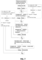
- the signal Air and PP ( RTT ) can be combined with each other, and a new common point can be found where the signals Sam and Air+ PP ( RTT ) start to be separated from each other. Detecting this point provides us the time delay between PP ( RTT ) and also PP ( t 1 ) , which is referred to as t 1 .
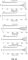
- the processing of the signals is shown in FIG. 12 .
- the Sam signal is shown without subtracting any PP
- the second section one can see the PP(RTT) signal that was yield by applying some phase and attenuation to the Ref signal and in the final section (below) subtraction of PP(RTT) signal from the Sam signal can be seen.
- the start of the signal can be seen at point number 93 and the return of the signal can be seen around point number 350.
- ⁇ 12 can also be determined.
- the corresponding corrected signal is named PP ( t 1 + t 2 ) U ( t - ( t 1 + t 2 )) .
- ⁇ 23 can be calculated immediately based on PP ( t 1 +t 2 ) U ( t- ( t 1 + t 2 )).
- FIG. 14 It illustrates all of PP ( mt 1 + nt 2 ) located in the time.
- step 8 the thickness of the final layer is determined. Although this could be derived based on the earlier results including t 3 and also ⁇ 23 , it is preferred to explicitly determine it, since this increases accuracy. All PP obtained in the previous step are now subtracted from the signal Sam. Then, PP ( t 1 + t 2 + t 3 ) is tracked. It is to be noticed that, while after finding t 3 in the above flowchart, the relative complex permittivity for third layer could be derived from ⁇ 23 and previous information, further calculation may be advantageous to decrease the error.
- the results for the relative permittivity and the thickness are determined based on the obtained values.
- Table 2 obtained results for a three-layer structure First layer Second layer Third layer Relative permittivity which is obtained 2.81-.14j 1.13-.04j 2.71-.10j Relative permittivity
- First layer Third layer 1.00+0.00j (air)
- First layer Third layer Thickness(mm) which is obtained 52.71 37.21 26.07 Thickness(mm) 50.04 30.11 20.08
- the transient radar method is applied to a single layer structure.
- a single thick PVE layer was monitored whereby the thickness of the layer is about 10.3cm.
- the signals can be captured and for example visualised on an oscilloscope. After capturing a smoothing process may be applied. In this way, processing can be performed on less noisy curves.
- One way of smoothing can be based on a histogram technique.
- the signals are correlated with each other, so the nose of the signal can be identified. The latter is illustrated in FIG. 15 , showing a part of the correlated signals.
- the air leakage is subtracted from the sample signal and the reference signal. This further allows to accurately see the nose.
- the signal corrected for air leakage is then subtracted from the sample signal.
- the signal Air and PP can be combined with each other, and a new common point can be find where the signals Sam and Air +PP ( RTT ) start to be separated from each other, i.e. the point where the deviation starts occurring. Detecting this point provides us the time delay between PP and also PP ( t 1 ) , which is referred to as t 1 .
- the processing of the signals is shown in FIG. 16 .
- the identification of t 1 also becomes clear when the signal PP ( t 1 ) is subtracted from the sample signal.
- the resulting physical parameter i.e. the thickness of the layer
- the resulting physical parameter i.e. the thickness of the layer
- Table 4 geometric and EM properties derived for a single layer Thickness(mm) (first layer) Permittivity( ⁇ r )
- Table 5 geometric and EM properties derived for a single layer.
- FIG 23 we illustrate the setup whereby as an example a 3-layer system is analyzed in transmission mode and as such is positioned between the emitting antenna and the receiver antenna.
- 3-layer system as indicated in FIG.1 also here one has nine unknown parameters to determine: the thickness and complex valued permittivity of each layer.
- phase jumps must be detected which occur from the nose up to at least 3 times bigger than the total "electromagnetic" thickness of the multilayer structure.
- the nose at the receiver can only be detected after the wave propagated the distance between the emitter and the front side of the multi-layer structure within a propagation time t in , all the single propagation paths through all layers j within a single propagation time tj i , and from the backside of the sample till the receiver within a propagation time t out , as illustrated by the PP (t 1 +t 2 +t 3 ) at the top in FIG. 24 .
- the next signal, which will be detected and which will lead to phase jumps in the receiver signal as illustrated in FIG. 25 will be related to one of the three following PPs: PP(3t 1 + t 2 +t 3 ), PP(t 1 +3t 2 +t 3 ), PP(t 1 +t 2 +3t 3 ).
- the layer with the smallest single propagation t i , time will yield the first contribution.
- more complex PP will be detected such PP((1+2m).t 1 + (1+2n).t 2 +(1+2p).t 3 ), whereby m, n, p ⁇ N and so on.
- the properties of the layers cannot be extracted one by one in the transient transmission signal when the number of superpositions in the transient reflection signal growths.
- the first six PP signals needs to be combined in a set of equations to extract the different layer properties in order to be able to derive 9 equations for 9 unknown parameters of a three-layer system.
- the capturing of the transient transmission signal after having detected the nose of the signal should last at least that long that the system of equations can be solved, meaning that for an N layered structure at least 3N equations can be derived, whereby N equations are related to the propagation paths in all layers, and 2N equations are related to captured phase transitions in the transient transmission signal
Landscapes
- Physics & Mathematics (AREA)
- Health & Medical Sciences (AREA)
- Analytical Chemistry (AREA)
- Spectroscopy & Molecular Physics (AREA)
- Life Sciences & Earth Sciences (AREA)
- Chemical & Material Sciences (AREA)
- Biochemistry (AREA)
- General Health & Medical Sciences (AREA)
- General Physics & Mathematics (AREA)
- Immunology (AREA)
- Pathology (AREA)
- Toxicology (AREA)
- Electromagnetism (AREA)
- Investigating Or Analysing Materials By Optical Means (AREA)
Claims (9)
- Ein Verfahren zum Bestimmen von Eigenschaften einer schichtbasierten Struktur, dadurch gekennzeichnet, dass das Verfahren umfasst- Bestrahlen der schichtbasierten Struktur wiederholt mit elektromagnetischer Strahlung mit kontinuierlicher Welle mit im Wesentlichen einer Frequenz im Bereich von 0,1 GHz bis 100 THz, wobei die elektromagnetische Welle einen transienten Teil von null bis zu einem monochromen stationären Zustand, und den stationären Zustandsteil umfasst, und
wobei eine Summe der Dauer des transienten Teils und der Dauer des stationären Zustandsteils mindestens gleich einer gesamten Rundfahrtszeit der elektromagnetischen Welle innerhalb der schichtbasierten Struktur ist, wobei die schichtbasierte Struktur ausreichend transparent für die verwendete elektromagnetische Strahlung ist,- Erfassen aus der wiederholten Bestrahlung in Abhängigkeit von der Zeit eines transienten Teils der Reflexion der elektromagnetischen Welle, die an verschiedenen Schnittstellen der schichtbasierten Struktur reflektiert wird, oder eines transienten Teils der Übertragung der elektromagnetischen Welle, die durch die verschiedenen Schnittstellen der schichtbasierten Struktur durchgelassen wird, durch Abtasten mit einer Frequenz mindestens der Wiederholungsfrequenz der emittierten Strahlung,- Ableiten aus dem transienten Teil der reflektierten oder durchgelassenen elektromagnetischen Welle in Abhängigkeit von der Zeitinformation in Bezug auf verschiedene Beiträge in dem transienten Teil der reflektierten oder durchgelassenen elektromagnetischen Welle, die aus den Reflexionen bei den oder Durchlässen durch die verschiedenen Schnittstellen der schichtbasierten Struktur stammen, wobei das Ableiten die Entfaltung des transienten Teils der reflektierten oder durchgelassenen elektromagnetischen Welle basierend auf einem Überlagerungsmodell der verschiedenen Beiträge im transienten Teil der reflektierten oder durchgelassenen elektromagnetischen Welle umfasst,- Bestimmen aus der Information mindestens einer geometrischen Information und/oder elektromagnetischer Eigenschaften der verschiedenen Schichten der schichtbasierten Struktur. - Ein Verfahren zum Bestimmen von Eigenschaften nach Anspruch 1, wobei das Ableiten Identifizieren verschiedener Zeitpunkte entsprechend verschiedener Beiträge zum reflektierten oder durchgelassenen Teil der elektromagnetischen Welle umfasst, die aus der Reflexion der elektromagnetischen Welle bei den, oder dem Durchlassen durch die verschiedenen Schnittstellen der schichtbasierten Struktur stammen.
- Ein Verfahren nach Anspruch 2, wobei das Bestimmen aus der Information mindestens einer geometrischen Information und/oder elektromagnetischer Eigenschaften das Bestimmen aus den verschiedenen Zeitpunkten mindestens einer geometrischen Information hinsichtlich verschiedener Schichten der schichtbasierten Struktur umfasst.
- Ein Verfahren nach einem der vorstehenden Ansprüche, wobei das Verfahren darüber hinaus das Glätten mindestens der erfassten reflektierten oder durchgelassenen elektromagnetischen Welle umfasst.
- Ein Verfahren nach einem der vorstehenden Ansprüche, wobei das Ableiten aus der Information mindestens einer geometrischen Information und/oder elektromagnetischer Eigenschaften das Ableiten einer Permittivität und/oder Durchlässigkeit der verschiedenen Schichten umfasst.
- Ein System (100) zum Charakterisieren einer schichtbasierten Struktur, dadurch gekennzeichnet, dass das System (100) umfasst- eine Bestrahlungsquelle (110), die angepasst ist, um eine wiederholte elektromagnetischer Strahlung mit kontinuierlicher Welle mit im Wesentlichen einer Frequenz im Bereich von 0,1 GHz bis 100 THz zu erzeugen, wobei die elektromagnetische Welle einen transienten Teil von null bis zu einem monochromen stationären Zustand, und den stationären Zustandsteil zum wiederholten Bestrahlen der schichtbasierten Struktur umfasst,- einen Empfänger (120), der zum Erfassen aus der wiederholten Bestrahlung in Abhängigkeit von der Zeit eines transienten Teils der Reflexion der elektromagnetischen Welle angepasst ist, die an verschiedenen Schnittstellen der schichtbasierten Struktur reflektiert wird, oder eines transienten Teils der Übertragung der elektromagnetischen Welle, die durch die verschiedenen Schnittstellen der schichtbasierten Struktur durchgelassen wird, durch Abtasten mit einer Frequenz mindestens der Wiederholungsfrequenz der emittierten Strahlung,- einen Prozessor (130), der programmiert ist, zum:(i) Steuern der Bestrahlungsquelle, sodass eine Summe der Dauer des transienten Teils und der Dauer des stationären Zustandsteils mindestens gleich einer gesamten Rundfahrtszeit der elektromagnetischen Welle innerhalb der schichtbasierten Struktur ist,(ii) Ableiten aus dem transienten Teil der reflektierten oder durchgelassenen elektromagnetischen Welle in Abhängigkeit von der Zeitinformation in Bezug auf verschiedene Beiträge in dem transienten Teil der reflektierten oder durchgelassenen elektromagnetischen Welle, die aus den Reflexionen bei den oder Durchlässen durch die verschiedenen Schnittstellen der schichtbasierten Struktur stammen, wobei das Ableiten die Entfaltung des transienten Teils der reflektierten oder durchgelassenen elektromagnetischen Welle basierend auf einem Überlagerungsmodell der verschiedenen Beiträge im transienten Teil der reflektierten oder durchgelassenen elektromagnetischen Welle umfasst,(iii) Bestimmen aus der Information mindestens einer geometrischen Information und/oder elektromagnetischer Eigenschaften der verschiedenen Schichten der schichtbasierten Struktur.
- Ein System (100) nach Anspruch 6, wobei das System (100) einen einschüssigen oder mehrschüssigen Sampler zum Sampeln des transienten Teils der reflektierten oder durchgelassenen elektromagnetischen Welle mit einer Frequenz von mindestens der Wiederholungsfrequenz der emittieren Strahlung umfasst.
- Ein Computerprogrammprodukt zum Bestimmen von Eigenschaften einer schichtbasierten Struktur, wobei das Computerprogrammprodukt Anweisungen umfasst, die, wenn sie in einem Prozessor ausgeführt werden, das System nach einem der Ansprüche 6 oder 7 veranlassen, die Schritte des Verfahrens nach einem der Ansprüche 1 bis 5 durchzuführen.
- Ein Datenträger, darin codiert ein Computerprogrammprodukt nach Anspruch 8 umfassend.
Applications Claiming Priority (2)
| Application Number | Priority Date | Filing Date | Title |
|---|---|---|---|
| EP2015173035 | 2015-06-19 | ||
| PCT/EP2016/064208 WO2016203049A1 (en) | 2015-06-19 | 2016-06-20 | Characterization of multilayer structures |
Publications (2)
| Publication Number | Publication Date |
|---|---|
| EP3311147A1 EP3311147A1 (de) | 2018-04-25 |
| EP3311147B1 true EP3311147B1 (de) | 2025-02-19 |
Family
ID=61656365
Family Applications (1)
| Application Number | Title | Priority Date | Filing Date |
|---|---|---|---|
| EP16733356.6A Active EP3311147B1 (de) | 2015-06-19 | 2016-06-20 | Charakterisierung von mehrschichtstrukturen |
Country Status (1)
| Country | Link |
|---|---|
| EP (1) | EP3311147B1 (de) |
Cited By (1)
| Publication number | Priority date | Publication date | Assignee | Title |
|---|---|---|---|---|
| EP4331821B1 (de) * | 2022-08-30 | 2025-12-24 | The Goodyear Tire & Rubber Company | Verfahren und vorrichtung zur terahertz-charakterisierung einer mehrschichtigen reifenlauffläche |
Families Citing this family (2)
| Publication number | Priority date | Publication date | Assignee | Title |
|---|---|---|---|---|
| LU100945B1 (en) * | 2018-09-28 | 2020-03-30 | Apollo Tyres Global R & D Bv | Method and control system for controlling a layer thickness of at least one layer of a layer-system based rubber article and corresponding extruding system |
| EP4641180B1 (de) | 2024-04-24 | 2026-05-06 | Vrije Universiteit Brussel | Asynchrone übergangssignalanalyse |
-
2016
- 2016-06-20 EP EP16733356.6A patent/EP3311147B1/de active Active
Cited By (1)
| Publication number | Priority date | Publication date | Assignee | Title |
|---|---|---|---|---|
| EP4331821B1 (de) * | 2022-08-30 | 2025-12-24 | The Goodyear Tire & Rubber Company | Verfahren und vorrichtung zur terahertz-charakterisierung einer mehrschichtigen reifenlauffläche |
Also Published As
| Publication number | Publication date |
|---|---|
| EP3311147A1 (de) | 2018-04-25 |
Similar Documents
| Publication | Publication Date | Title |
|---|---|---|
| US11085874B2 (en) | Characterization of multilayer structures | |
| JP5684819B2 (ja) | 単層物体及び多層物体の界面特性を検出及び測定するシステム及び方法 | |
| CN108519059B (zh) | 基于反射型太赫兹时域光谱技术的热障涂层多层厚度检测方法 | |
| US20180156728A1 (en) | Characterization of multilayer structures | |
| US20130048859A1 (en) | Sample analysis using terahertz spectroscopy | |
| Hedayatrasa et al. | Performance of frequency and/or phase modulated excitation waveforms for optical infrared thermography of CFRPs through thermal wave radar: A simulation study | |
| CN105333841B (zh) | 基于反射型太赫兹时域光谱的金属表面粗糙度检测方法 | |
| US20240044845A1 (en) | Ultrasonic system and method for detecting and characterizing contact delaminations | |
| CN113884014B (zh) | 一种太赫兹金属基底多涂层高分辨厚度测量方法及装置 | |
| EP3311147B1 (de) | Charakterisierung von mehrschichtstrukturen | |
| Draudviliene et al. | Assessment of quantitative and qualitative characteristics of ultrasonic guided wave phase velocity measurement technique | |
| JP2016530539A (ja) | 非破壊材料特性解析導波管プローブ | |
| Akbar et al. | Delamination detection in glass-fibre reinforced polymer (GFRP) using microwave time domain reflectometry | |
| JP2019095438A (ja) | ランプを有する構造体の超音波検査 | |
| Xu et al. | Physics induced terahertz time-of-flight compensation method for accurate thickness measurement and full-field imaging of damage in composite | |
| US9599576B1 (en) | Acoustic—RF multi-sensor material characterization system | |
| Shafi et al. | Applied microwave imaging of composite structures using open-ended circular waveguide | |
| Gubinelli et al. | An ultra-wideband radar approach to nondestructive testing | |
| Chady et al. | Testing of glass-fiber reinforced composite materials using terahertz technique | |
| Pałka et al. | Monitoring of air voids at plastic-metal interfaces by terahertz radiation | |
| Broberg et al. | Improved corner detection by ultrasonic testing using phase analysis | |
| Rizwan et al. | Contextual application of pulse-compression and multi-frequency distance-gain size analysis in ultrasonic inspection of forging | |
| Pourkazemi et al. | Novel illumination and parameter extraction technique for the characterization of multilayer structures in the GHz range with deep sub-wavelength resolution | |
| Winfree et al. | Detection and characterization of flaws in sprayed on foam insulation with pulsed terahertz frequency electromagnetic waves | |
| Beckmann et al. | THz applications for non-destructive testing |
Legal Events
| Date | Code | Title | Description |
|---|---|---|---|
| STAA | Information on the status of an ep patent application or granted ep patent |
Free format text: STATUS: THE INTERNATIONAL PUBLICATION HAS BEEN MADE |
|
| PUAI | Public reference made under article 153(3) epc to a published international application that has entered the european phase |
Free format text: ORIGINAL CODE: 0009012 |
|
| STAA | Information on the status of an ep patent application or granted ep patent |
Free format text: STATUS: REQUEST FOR EXAMINATION WAS MADE |
|
| 17P | Request for examination filed |
Effective date: 20171218 |
|
| AK | Designated contracting states |
Kind code of ref document: A1 Designated state(s): AL AT BE BG CH CY CZ DE DK EE ES FI FR GB GR HR HU IE IS IT LI LT LU LV MC MK MT NL NO PL PT RO RS SE SI SK SM TR |
|
| AX | Request for extension of the european patent |
Extension state: BA ME |
|
| DAV | Request for validation of the european patent (deleted) | ||
| DAX | Request for extension of the european patent (deleted) | ||
| STAA | Information on the status of an ep patent application or granted ep patent |
Free format text: STATUS: EXAMINATION IS IN PROGRESS |
|
| 17Q | First examination report despatched |
Effective date: 20200506 |
|
| GRAP | Despatch of communication of intention to grant a patent |
Free format text: ORIGINAL CODE: EPIDOSNIGR1 |
|
| STAA | Information on the status of an ep patent application or granted ep patent |
Free format text: STATUS: GRANT OF PATENT IS INTENDED |
|
| RIC1 | Information provided on ipc code assigned before grant |
Ipc: G01N 21/84 20060101ALI20240918BHEP Ipc: G01N 21/3581 20140101ALI20240918BHEP Ipc: G01N 22/00 20060101AFI20240918BHEP |
|
| INTG | Intention to grant announced |
Effective date: 20240926 |
|
| GRAS | Grant fee paid |
Free format text: ORIGINAL CODE: EPIDOSNIGR3 |
|
| GRAA | (expected) grant |
Free format text: ORIGINAL CODE: 0009210 |
|
| STAA | Information on the status of an ep patent application or granted ep patent |
Free format text: STATUS: THE PATENT HAS BEEN GRANTED |
|
| AK | Designated contracting states |
Kind code of ref document: B1 Designated state(s): AL AT BE BG CH CY CZ DE DK EE ES FI FR GB GR HR HU IE IS IT LI LT LU LV MC MK MT NL NO PL PT RO RS SE SI SK SM TR |
|
| REG | Reference to a national code |
Ref country code: GB Ref legal event code: FG4D |
|
| REG | Reference to a national code |
Ref country code: CH Ref legal event code: EP |
|
| REG | Reference to a national code |
Ref country code: DE Ref legal event code: R096 Ref document number: 602016091270 Country of ref document: DE |
|
| REG | Reference to a national code |
Ref country code: IE Ref legal event code: FG4D |
|
| P01 | Opt-out of the competence of the unified patent court (upc) registered |
Free format text: CASE NUMBER: APP_12547/2025 Effective date: 20250319 |
|
| REG | Reference to a national code |
Ref country code: NL Ref legal event code: FP |
|
| PG25 | Lapsed in a contracting state [announced via postgrant information from national office to epo] |
Ref country code: RS Free format text: LAPSE BECAUSE OF FAILURE TO SUBMIT A TRANSLATION OF THE DESCRIPTION OR TO PAY THE FEE WITHIN THE PRESCRIBED TIME-LIMIT Effective date: 20250519 |
|
| PG25 | Lapsed in a contracting state [announced via postgrant information from national office to epo] |
Ref country code: FI Free format text: LAPSE BECAUSE OF FAILURE TO SUBMIT A TRANSLATION OF THE DESCRIPTION OR TO PAY THE FEE WITHIN THE PRESCRIBED TIME-LIMIT Effective date: 20250219 |
|
| PG25 | Lapsed in a contracting state [announced via postgrant information from national office to epo] |
Ref country code: PL Free format text: LAPSE BECAUSE OF FAILURE TO SUBMIT A TRANSLATION OF THE DESCRIPTION OR TO PAY THE FEE WITHIN THE PRESCRIBED TIME-LIMIT Effective date: 20250219 |
|
| PGFP | Annual fee paid to national office [announced via postgrant information from national office to epo] |
Ref country code: DE Payment date: 20250618 Year of fee payment: 10 |
|
| PG25 | Lapsed in a contracting state [announced via postgrant information from national office to epo] |
Ref country code: ES Free format text: LAPSE BECAUSE OF FAILURE TO SUBMIT A TRANSLATION OF THE DESCRIPTION OR TO PAY THE FEE WITHIN THE PRESCRIBED TIME-LIMIT Effective date: 20250219 |
|
| PGFP | Annual fee paid to national office [announced via postgrant information from national office to epo] |
Ref country code: GB Payment date: 20250618 Year of fee payment: 10 |
|
| REG | Reference to a national code |
Ref country code: LT Ref legal event code: MG9D |
|
| PG25 | Lapsed in a contracting state [announced via postgrant information from national office to epo] |
Ref country code: IS Free format text: LAPSE BECAUSE OF FAILURE TO SUBMIT A TRANSLATION OF THE DESCRIPTION OR TO PAY THE FEE WITHIN THE PRESCRIBED TIME-LIMIT Effective date: 20250619 Ref country code: NO Free format text: LAPSE BECAUSE OF FAILURE TO SUBMIT A TRANSLATION OF THE DESCRIPTION OR TO PAY THE FEE WITHIN THE PRESCRIBED TIME-LIMIT Effective date: 20250519 |
|
| PGFP | Annual fee paid to national office [announced via postgrant information from national office to epo] |
Ref country code: NL Payment date: 20250618 Year of fee payment: 10 Ref country code: BE Payment date: 20250618 Year of fee payment: 10 |
|
| PG25 | Lapsed in a contracting state [announced via postgrant information from national office to epo] |
Ref country code: HR Free format text: LAPSE BECAUSE OF FAILURE TO SUBMIT A TRANSLATION OF THE DESCRIPTION OR TO PAY THE FEE WITHIN THE PRESCRIBED TIME-LIMIT Effective date: 20250219 |
|
| PG25 | Lapsed in a contracting state [announced via postgrant information from national office to epo] |
Ref country code: PT Free format text: LAPSE BECAUSE OF FAILURE TO SUBMIT A TRANSLATION OF THE DESCRIPTION OR TO PAY THE FEE WITHIN THE PRESCRIBED TIME-LIMIT Effective date: 20250620 Ref country code: LV Free format text: LAPSE BECAUSE OF FAILURE TO SUBMIT A TRANSLATION OF THE DESCRIPTION OR TO PAY THE FEE WITHIN THE PRESCRIBED TIME-LIMIT Effective date: 20250219 |
|
| PG25 | Lapsed in a contracting state [announced via postgrant information from national office to epo] |
Ref country code: GR Free format text: LAPSE BECAUSE OF FAILURE TO SUBMIT A TRANSLATION OF THE DESCRIPTION OR TO PAY THE FEE WITHIN THE PRESCRIBED TIME-LIMIT Effective date: 20250520 Ref country code: BG Free format text: LAPSE BECAUSE OF FAILURE TO SUBMIT A TRANSLATION OF THE DESCRIPTION OR TO PAY THE FEE WITHIN THE PRESCRIBED TIME-LIMIT Effective date: 20250219 |
|
| REG | Reference to a national code |
Ref country code: AT Ref legal event code: MK05 Ref document number: 1768706 Country of ref document: AT Kind code of ref document: T Effective date: 20250219 |
|
| PG25 | Lapsed in a contracting state [announced via postgrant information from national office to epo] |
Ref country code: SE Free format text: LAPSE BECAUSE OF FAILURE TO SUBMIT A TRANSLATION OF THE DESCRIPTION OR TO PAY THE FEE WITHIN THE PRESCRIBED TIME-LIMIT Effective date: 20250219 |
|
| PG25 | Lapsed in a contracting state [announced via postgrant information from national office to epo] |
Ref country code: SM Free format text: LAPSE BECAUSE OF FAILURE TO SUBMIT A TRANSLATION OF THE DESCRIPTION OR TO PAY THE FEE WITHIN THE PRESCRIBED TIME-LIMIT Effective date: 20250219 |
|
| PG25 | Lapsed in a contracting state [announced via postgrant information from national office to epo] |
Ref country code: DK Free format text: LAPSE BECAUSE OF FAILURE TO SUBMIT A TRANSLATION OF THE DESCRIPTION OR TO PAY THE FEE WITHIN THE PRESCRIBED TIME-LIMIT Effective date: 20250219 |
|
| PG25 | Lapsed in a contracting state [announced via postgrant information from national office to epo] |
Ref country code: IT Free format text: LAPSE BECAUSE OF FAILURE TO SUBMIT A TRANSLATION OF THE DESCRIPTION OR TO PAY THE FEE WITHIN THE PRESCRIBED TIME-LIMIT Effective date: 20250219 |
|
| PG25 | Lapsed in a contracting state [announced via postgrant information from national office to epo] |
Ref country code: AT Free format text: LAPSE BECAUSE OF FAILURE TO SUBMIT A TRANSLATION OF THE DESCRIPTION OR TO PAY THE FEE WITHIN THE PRESCRIBED TIME-LIMIT Effective date: 20250219 |
|
| PG25 | Lapsed in a contracting state [announced via postgrant information from national office to epo] |
Ref country code: CZ Free format text: LAPSE BECAUSE OF FAILURE TO SUBMIT A TRANSLATION OF THE DESCRIPTION OR TO PAY THE FEE WITHIN THE PRESCRIBED TIME-LIMIT Effective date: 20250219 Ref country code: EE Free format text: LAPSE BECAUSE OF FAILURE TO SUBMIT A TRANSLATION OF THE DESCRIPTION OR TO PAY THE FEE WITHIN THE PRESCRIBED TIME-LIMIT Effective date: 20250219 |
|
| PG25 | Lapsed in a contracting state [announced via postgrant information from national office to epo] |
Ref country code: RO Free format text: LAPSE BECAUSE OF FAILURE TO SUBMIT A TRANSLATION OF THE DESCRIPTION OR TO PAY THE FEE WITHIN THE PRESCRIBED TIME-LIMIT Effective date: 20250219 |
|
| PG25 | Lapsed in a contracting state [announced via postgrant information from national office to epo] |
Ref country code: SK Free format text: LAPSE BECAUSE OF FAILURE TO SUBMIT A TRANSLATION OF THE DESCRIPTION OR TO PAY THE FEE WITHIN THE PRESCRIBED TIME-LIMIT Effective date: 20250219 |
|
| REG | Reference to a national code |
Ref country code: DE Ref legal event code: R097 Ref document number: 602016091270 Country of ref document: DE |
|
| PLBE | No opposition filed within time limit |
Free format text: ORIGINAL CODE: 0009261 |
|
| STAA | Information on the status of an ep patent application or granted ep patent |
Free format text: STATUS: NO OPPOSITION FILED WITHIN TIME LIMIT |
|
| REG | Reference to a national code |
Ref country code: CH Ref legal event code: L10 Free format text: ST27 STATUS EVENT CODE: U-0-0-L10-L00 (AS PROVIDED BY THE NATIONAL OFFICE) Effective date: 20251231 |
|
| REG | Reference to a national code |
Ref country code: CH Ref legal event code: H13 Free format text: ST27 STATUS EVENT CODE: U-0-0-H10-H13 (AS PROVIDED BY THE NATIONAL OFFICE) Effective date: 20260127 |
|
| 26N | No opposition filed |
Effective date: 20251120 |
|
| PG25 | Lapsed in a contracting state [announced via postgrant information from national office to epo] |
Ref country code: MC Free format text: LAPSE BECAUSE OF FAILURE TO SUBMIT A TRANSLATION OF THE DESCRIPTION OR TO PAY THE FEE WITHIN THE PRESCRIBED TIME-LIMIT Effective date: 20250219 |
|
| PG25 | Lapsed in a contracting state [announced via postgrant information from national office to epo] |
Ref country code: LU Free format text: LAPSE BECAUSE OF NON-PAYMENT OF DUE FEES Effective date: 20250620 |
|
| PG25 | Lapsed in a contracting state [announced via postgrant information from national office to epo] |
Ref country code: IE Free format text: LAPSE BECAUSE OF NON-PAYMENT OF DUE FEES Effective date: 20250620 |
|
| PG25 | Lapsed in a contracting state [announced via postgrant information from national office to epo] |
Ref country code: FR Free format text: LAPSE BECAUSE OF NON-PAYMENT OF DUE FEES Effective date: 20250630 |
|
| PG25 | Lapsed in a contracting state [announced via postgrant information from national office to epo] |
Ref country code: CH Free format text: LAPSE BECAUSE OF NON-PAYMENT OF DUE FEES Effective date: 20250630 |