EP3311035B1 - Agricultural implement and method of supplying hydraulic power to an agricultural implement - Google Patents
Agricultural implement and method of supplying hydraulic power to an agricultural implement Download PDFInfo
- Publication number
- EP3311035B1 EP3311035B1 EP16738892.5A EP16738892A EP3311035B1 EP 3311035 B1 EP3311035 B1 EP 3311035B1 EP 16738892 A EP16738892 A EP 16738892A EP 3311035 B1 EP3311035 B1 EP 3311035B1
- Authority
- EP
- European Patent Office
- Prior art keywords
- pressure
- load
- agricultural implement
- sensing line
- flow
- Prior art date
- Legal status (The legal status is an assumption and is not a legal conclusion. Google has not performed a legal analysis and makes no representation as to the accuracy of the status listed.)
- Active
Links
Images


Classifications
-
- F—MECHANICAL ENGINEERING; LIGHTING; HEATING; WEAPONS; BLASTING
- F15—FLUID-PRESSURE ACTUATORS; HYDRAULICS OR PNEUMATICS IN GENERAL
- F15B—SYSTEMS ACTING BY MEANS OF FLUIDS IN GENERAL; FLUID-PRESSURE ACTUATORS, e.g. SERVOMOTORS; DETAILS OF FLUID-PRESSURE SYSTEMS, NOT OTHERWISE PROVIDED FOR
- F15B11/00—Servomotor systems without provision for follow-up action; Circuits therefor
- F15B11/02—Systems essentially incorporating special features for controlling the speed or actuating force of an output member
- F15B11/04—Systems essentially incorporating special features for controlling the speed or actuating force of an output member for controlling the speed
- F15B11/05—Systems essentially incorporating special features for controlling the speed or actuating force of an output member for controlling the speed specially adapted to maintain constant speed, e.g. pressure-compensated, load-responsive
- F15B11/055—Systems essentially incorporating special features for controlling the speed or actuating force of an output member for controlling the speed specially adapted to maintain constant speed, e.g. pressure-compensated, load-responsive by adjusting the pump output or bypass
-
- A—HUMAN NECESSITIES
- A01—AGRICULTURE; FORESTRY; ANIMAL HUSBANDRY; HUNTING; TRAPPING; FISHING
- A01B—SOIL WORKING IN AGRICULTURE OR FORESTRY; PARTS, DETAILS, OR ACCESSORIES OF AGRICULTURAL MACHINES OR IMPLEMENTS, IN GENERAL
- A01B63/00—Lifting or adjusting devices or arrangements for agricultural machines or implements
- A01B63/14—Lifting or adjusting devices or arrangements for agricultural machines or implements for implements drawn by animals or tractors
- A01B63/24—Tools or tool-holders adjustable relatively to the frame
- A01B63/32—Tools or tool-holders adjustable relatively to the frame operated by hydraulic or pneumatic means without automatic control
-
- A—HUMAN NECESSITIES
- A01—AGRICULTURE; FORESTRY; ANIMAL HUSBANDRY; HUNTING; TRAPPING; FISHING
- A01B—SOIL WORKING IN AGRICULTURE OR FORESTRY; PARTS, DETAILS, OR ACCESSORIES OF AGRICULTURAL MACHINES OR IMPLEMENTS, IN GENERAL
- A01B63/00—Lifting or adjusting devices or arrangements for agricultural machines or implements
- A01B63/02—Lifting or adjusting devices or arrangements for agricultural machines or implements for implements mounted on tractors
- A01B63/10—Lifting or adjusting devices or arrangements for agricultural machines or implements for implements mounted on tractors operated by hydraulic or pneumatic means
- A01B63/111—Lifting or adjusting devices or arrangements for agricultural machines or implements for implements mounted on tractors operated by hydraulic or pneumatic means regulating working depth of implements
- A01B63/112—Lifting or adjusting devices or arrangements for agricultural machines or implements for implements mounted on tractors operated by hydraulic or pneumatic means regulating working depth of implements to control draught load, i.e. tractive force
-
- F—MECHANICAL ENGINEERING; LIGHTING; HEATING; WEAPONS; BLASTING
- F15—FLUID-PRESSURE ACTUATORS; HYDRAULICS OR PNEUMATICS IN GENERAL
- F15B—SYSTEMS ACTING BY MEANS OF FLUIDS IN GENERAL; FLUID-PRESSURE ACTUATORS, e.g. SERVOMOTORS; DETAILS OF FLUID-PRESSURE SYSTEMS, NOT OTHERWISE PROVIDED FOR
- F15B11/00—Servomotor systems without provision for follow-up action; Circuits therefor
- F15B11/02—Systems essentially incorporating special features for controlling the speed or actuating force of an output member
- F15B11/04—Systems essentially incorporating special features for controlling the speed or actuating force of an output member for controlling the speed
- F15B11/05—Systems essentially incorporating special features for controlling the speed or actuating force of an output member for controlling the speed specially adapted to maintain constant speed, e.g. pressure-compensated, load-responsive
-
- F—MECHANICAL ENGINEERING; LIGHTING; HEATING; WEAPONS; BLASTING
- F15—FLUID-PRESSURE ACTUATORS; HYDRAULICS OR PNEUMATICS IN GENERAL
- F15B—SYSTEMS ACTING BY MEANS OF FLUIDS IN GENERAL; FLUID-PRESSURE ACTUATORS, e.g. SERVOMOTORS; DETAILS OF FLUID-PRESSURE SYSTEMS, NOT OTHERWISE PROVIDED FOR
- F15B11/00—Servomotor systems without provision for follow-up action; Circuits therefor
- F15B11/16—Servomotor systems without provision for follow-up action; Circuits therefor with two or more servomotors
- F15B11/161—Servomotor systems without provision for follow-up action; Circuits therefor with two or more servomotors with sensing of servomotor demand or load
-
- F—MECHANICAL ENGINEERING; LIGHTING; HEATING; WEAPONS; BLASTING
- F15—FLUID-PRESSURE ACTUATORS; HYDRAULICS OR PNEUMATICS IN GENERAL
- F15B—SYSTEMS ACTING BY MEANS OF FLUIDS IN GENERAL; FLUID-PRESSURE ACTUATORS, e.g. SERVOMOTORS; DETAILS OF FLUID-PRESSURE SYSTEMS, NOT OTHERWISE PROVIDED FOR
- F15B2211/00—Circuits for servomotor systems
- F15B2211/20—Fluid pressure source, e.g. accumulator or variable axial piston pump
- F15B2211/205—Systems with pumps
- F15B2211/2053—Type of pump
- F15B2211/20546—Type of pump variable capacity
- F15B2211/20553—Type of pump variable capacity with pilot circuit, e.g. for controlling a swash plate
-
- F—MECHANICAL ENGINEERING; LIGHTING; HEATING; WEAPONS; BLASTING
- F15—FLUID-PRESSURE ACTUATORS; HYDRAULICS OR PNEUMATICS IN GENERAL
- F15B—SYSTEMS ACTING BY MEANS OF FLUIDS IN GENERAL; FLUID-PRESSURE ACTUATORS, e.g. SERVOMOTORS; DETAILS OF FLUID-PRESSURE SYSTEMS, NOT OTHERWISE PROVIDED FOR
- F15B2211/00—Circuits for servomotor systems
- F15B2211/40—Flow control
- F15B2211/415—Flow control characterised by the connections of the flow control means in the circuit
- F15B2211/41509—Flow control characterised by the connections of the flow control means in the circuit being connected to a pressure source and a directional control valve
-
- F—MECHANICAL ENGINEERING; LIGHTING; HEATING; WEAPONS; BLASTING
- F15—FLUID-PRESSURE ACTUATORS; HYDRAULICS OR PNEUMATICS IN GENERAL
- F15B—SYSTEMS ACTING BY MEANS OF FLUIDS IN GENERAL; FLUID-PRESSURE ACTUATORS, e.g. SERVOMOTORS; DETAILS OF FLUID-PRESSURE SYSTEMS, NOT OTHERWISE PROVIDED FOR
- F15B2211/00—Circuits for servomotor systems
- F15B2211/40—Flow control
- F15B2211/415—Flow control characterised by the connections of the flow control means in the circuit
- F15B2211/41527—Flow control characterised by the connections of the flow control means in the circuit being connected to an output member and a directional control valve
-
- F—MECHANICAL ENGINEERING; LIGHTING; HEATING; WEAPONS; BLASTING
- F15—FLUID-PRESSURE ACTUATORS; HYDRAULICS OR PNEUMATICS IN GENERAL
- F15B—SYSTEMS ACTING BY MEANS OF FLUIDS IN GENERAL; FLUID-PRESSURE ACTUATORS, e.g. SERVOMOTORS; DETAILS OF FLUID-PRESSURE SYSTEMS, NOT OTHERWISE PROVIDED FOR
- F15B2211/00—Circuits for servomotor systems
- F15B2211/40—Flow control
- F15B2211/415—Flow control characterised by the connections of the flow control means in the circuit
- F15B2211/41572—Flow control characterised by the connections of the flow control means in the circuit being connected to a pressure source and an output member
-
- F—MECHANICAL ENGINEERING; LIGHTING; HEATING; WEAPONS; BLASTING
- F15—FLUID-PRESSURE ACTUATORS; HYDRAULICS OR PNEUMATICS IN GENERAL
- F15B—SYSTEMS ACTING BY MEANS OF FLUIDS IN GENERAL; FLUID-PRESSURE ACTUATORS, e.g. SERVOMOTORS; DETAILS OF FLUID-PRESSURE SYSTEMS, NOT OTHERWISE PROVIDED FOR
- F15B2211/00—Circuits for servomotor systems
- F15B2211/50—Pressure control
- F15B2211/515—Pressure control characterised by the connections of the pressure control means in the circuit
- F15B2211/5151—Pressure control characterised by the connections of the pressure control means in the circuit being connected to a pressure source and a directional control valve
-
- F—MECHANICAL ENGINEERING; LIGHTING; HEATING; WEAPONS; BLASTING
- F15—FLUID-PRESSURE ACTUATORS; HYDRAULICS OR PNEUMATICS IN GENERAL
- F15B—SYSTEMS ACTING BY MEANS OF FLUIDS IN GENERAL; FLUID-PRESSURE ACTUATORS, e.g. SERVOMOTORS; DETAILS OF FLUID-PRESSURE SYSTEMS, NOT OTHERWISE PROVIDED FOR
- F15B2211/00—Circuits for servomotor systems
- F15B2211/50—Pressure control
- F15B2211/515—Pressure control characterised by the connections of the pressure control means in the circuit
- F15B2211/5153—Pressure control characterised by the connections of the pressure control means in the circuit being connected to an output member and a directional control valve
-
- F—MECHANICAL ENGINEERING; LIGHTING; HEATING; WEAPONS; BLASTING
- F15—FLUID-PRESSURE ACTUATORS; HYDRAULICS OR PNEUMATICS IN GENERAL
- F15B—SYSTEMS ACTING BY MEANS OF FLUIDS IN GENERAL; FLUID-PRESSURE ACTUATORS, e.g. SERVOMOTORS; DETAILS OF FLUID-PRESSURE SYSTEMS, NOT OTHERWISE PROVIDED FOR
- F15B2211/00—Circuits for servomotor systems
- F15B2211/50—Pressure control
- F15B2211/515—Pressure control characterised by the connections of the pressure control means in the circuit
- F15B2211/5158—Pressure control characterised by the connections of the pressure control means in the circuit being connected to a pressure source and an output member
-
- F—MECHANICAL ENGINEERING; LIGHTING; HEATING; WEAPONS; BLASTING
- F15—FLUID-PRESSURE ACTUATORS; HYDRAULICS OR PNEUMATICS IN GENERAL
- F15B—SYSTEMS ACTING BY MEANS OF FLUIDS IN GENERAL; FLUID-PRESSURE ACTUATORS, e.g. SERVOMOTORS; DETAILS OF FLUID-PRESSURE SYSTEMS, NOT OTHERWISE PROVIDED FOR
- F15B2211/00—Circuits for servomotor systems
- F15B2211/60—Circuit components or control therefor
- F15B2211/605—Load sensing circuits
-
- F—MECHANICAL ENGINEERING; LIGHTING; HEATING; WEAPONS; BLASTING
- F15—FLUID-PRESSURE ACTUATORS; HYDRAULICS OR PNEUMATICS IN GENERAL
- F15B—SYSTEMS ACTING BY MEANS OF FLUIDS IN GENERAL; FLUID-PRESSURE ACTUATORS, e.g. SERVOMOTORS; DETAILS OF FLUID-PRESSURE SYSTEMS, NOT OTHERWISE PROVIDED FOR
- F15B2211/00—Circuits for servomotor systems
- F15B2211/60—Circuit components or control therefor
- F15B2211/65—Methods of control of the load sensing pressure
- F15B2211/652—Methods of control of the load sensing pressure the load sensing pressure being different from the load pressure
Definitions
- This document relates to an agricultural implement which is to be supplied with hydraulic power via a load sensing system, known as an "LS system", from a traction vehicle, and to a method of supplying hydraulic power to an agricultural implement.
- LS system load sensing system
- LS systems load sensing systems
- Fig. 1 shows such a system, comprising an agricultural implement 1 which has two loads L1, L2 which can be constituted by hydraulic cylinders for lowering frame sections of the agricultural implement or for setting a working depth, or by hydraulic motors for operating feeder equipment for sowing seeds, for example, or for operating a blower, pump or suchlike.
- loads L1, L2 which can be constituted by hydraulic cylinders for lowering frame sections of the agricultural implement or for setting a working depth, or by hydraulic motors for operating feeder equipment for sowing seeds, for example, or for operating a blower, pump or suchlike.
- the LS system comprises, in the traction vehicle 2, a variable pump 21, a reservoir 22 for hydraulic fluid and a power source PS which can be a combustion engine or an electric motor.
- the pump can be a hydraulic pump with variable displacement.
- the LS system comprises three lines: a feed line P, a return line T and a load-sensing line LS. Via the feed line P, hydraulic fluid is fed from the reservoir 22 via the pump 21 to the agricultural implement 1.
- a hydraulic measuring signal is produced, which can, for example, indicate a maximum occurring pressure at a point in the hydraulic system of the agricultural implement 1.
- the operation of the pump is controlled so that a predetermined pressure is maintained.
- LS systems have the advantage that several functions, here represented by function valves FV1, FV2 and loads L1 and L2 operated by them, can be supplied with a small number of lines between the traction vehicle and the agricultural implement, wherein the supply from the pump 21 via the feed line P is automatically adjusted in relation to the agricultural implement's requirements as a whole.
- the function valves can be manually-controlled valves, electrically-controlled valves, pneumatically-controlled valves or hydraulically-controlled valves.
- EP1338934A1 discloses a method of controlling agricultural working machines.
- One aim is therefore to provide an improved agricultural implement. Specific aims include providing an agricultural implement which is less sensitive to leakage, wear and/or friction (line losses) in the hydraulic system and/or which more probably is fully functional with tractors of different makes or models. A further aim is to improve the energy efficiency of the outfit comprising the agricultural implement.
- an agricultural implement (1', 1") which has at least one hydraulically activated function, said agricultural implement comprising an incoming feed line for hydraulic fluid, an outgoing return line for hydraulic fluid and an outgoing load-sensing line.
- the agricultural implement also comprise a sensor device for detecting a pressure in relation to the hydraulically-operated function and/or in relation to the load-sensing line, a regulating device which is hydraulically connected to the load-sensing line and to at least one of the feed line or return line, and a control unit which is arranged to receive a signal from the sensor device and to control the regulating device to provide a predetermined pressure and/or flow on the load-sensing line.
- an "agricultural implement” primarily refers to an arbitrary device for use in agriculture. More specifically if refers to soil-working agricultural implements, which includes ploughs, harrows, cultivators and sowing machines as well as combinations thereof.
- Hydraulicically activated function refers to such functions that are activated, controlled or driven by way of supplying hydraulic fluid, for example hydraulic oil.
- Non-restrictive examples of such functions include hydraulic cylinders for extending and/or retracting frame sections of the agricultural implement, hydraulic cylinders for setting, for example, working depths, and hydraulically-driven motors for blowers or feeding out devices.
- a hydraulically-operated function can be controlled manually (i.e. with aid of a lever or button), hydraulically, electrically or pneumatically.
- the predetermined pressure and/or flow can be given by a user or calculated in a suitable manner depending on the circumstances.
- the predetermined pressure or flow can be given as a single value or as a value interval.
- the predetermined pressure and/or flow can vary over time.
- a pressure is taken to mean at least one pressure, for example one or several pressures can be detected in relation to the hydraulically activated function and/or in relation to the load-sensing line.
- the agricultural implement can also comprise at least one function valve which is connected to the feed line for activating a first load.
- "Functional valve” is taken to mean a valve for a hydraulically activated function. As stated above, such a valve can be a manually, electrically, hydraulically or pneumatically controlled valve.
- the load can, for example, be an aforementioned hydraulic cylinder or motor.
- the agricultural implement can also comprise a first sensor upstream of the function valve and a second sensor downstream of the function valve.
- the sensor can, but does not have to be, of the same type.
- One or more sensors can form part of a sensor device which can also comprise signal lines and/or transmitters/receivers, amplifiers and signal processing systems, possibly memories and interfaces for communication with other units.
- the sensor device can be set up to sense a pressure in relation to the hydraulically activated function and/or in relation to the load-sensing line, and the control system can be set up to control said pressure and/or flow on the load-sensing line so that a predetermined pressure and/or flow is brought about on the load-sensing line.
- the sensor device can be set up to sense a pressure difference over the function valve and the control system can be set up to control said pressure and/or flow on the load-sensing line so that a predetermined pressure difference is maintained.
- the predetermined pressure difference can be given by a user or calculated in a suitable manner depending on the circumstances.
- the predetermined pressure difference can be given as a single value or as a value interval.
- the predetermined pressure difference can vary over time.
- the sensor device can comprise an LS pressure sensor downstream of the regulating device for detecting a pressure brought about in a load-sensing line, and the control device can be set up to control said pressure and/or flow on the load-sensing line so that a predetermined pressure and/or flow is brought about on the load-sensing line.
- the pump pressure can be changed, for example it can increase, due to reasons other than being brought about through a signal on the load-sensing line.
- This can lead to problems for the control unit as it can be made to change the pressure and/or flow on the load-sensing line, not as a result of changed conditions on the agricultural implement, but as a result of a circumstance on the traction vehicle. This can in turn lead to undesirable variations in pressure and/or flow in the load-sensing line and thereby also the supply to the agricultural implement.
- At least one of said first and second sensors can be set up to produce a hydraulic signal for the control unit.
- At least one of said first and second sensors can be set up to produce an electrical signal for the control unit.
- the regulating device can be connected to both the feed line and the return line.
- the control system can be set up to control the pressure and/or flow on the load-sensing line in order to provide a predetermined pressure in relation to the hydraulically activated function.
- the control unit can be a hydraulic or electric control unit.
- the agricultural implement can also comprise a second hydraulically activated function and a second sensor device for detecting a second pressure in relation to the second hydraulically activated function, wherein the control unit can be set up to receive a second signal from the second sensor device and to control the pressure and/or flow on the load-sensing line also based on the second signal.
- a method of supplying hydraulic power to an agricultural implement comprises supplying via a feed line pressurised hydraulic fluid to the agricultural implement from a hydraulic drive system to at least one hydraulically activated function, via a return line returning the hydraulic fluid to the hydraulic drive system, and via a load-sensing line sending a signal pressure back for controlling the hydraulic drive system.
- the method also comprises measuring a pressure in relation to the hydraulically activated function and through a hydraulic connection between the feed line and/or the return line and the load-sensing line controlling a pressure and/or flow on the load-sensing line based on the measured pressure.
- the method can also comprise measuring a pressure difference over a function valve and controlling said pressure and/or flow on the load-sensing line based on the measured pressure difference.
- the method can also comprise detecting a pressure and/or flow on the load-sensing line and controlling said pressure and/or flow on the load-sensing line so that a predetermined pressure and/or flow is brought about on the load-sensing line.
- the method can also comprise measuring a second pressure in relation to a second hydraulically activated function and controlling the pressure and/or flow on the load-sensing line also based on the second pressure.
- the agricultural implement 1, 1', 1" can be a soil-working agricultural implement such as a harrow, a plough, a cultivator and sowing machine or a combination thereof.
- the agricultural implement 1' comprises a load, which can be of a type such as described above.
- the agricultural implement 1' comprises a function valve FV, which can be of a type such as described above.
- a first pressure sensor p_P for measuring a pressure upstream of the function valve FV is connected between the feed line P and function valve FV.
- a second pressure sensor p_L for measuring a pressure downstream of the function valve FV is connected between the function valve and load.
- the pressure sensors p_P, p_L can be of a type which provides a signal of discretionary type, e.g. electrical or hydraulic.
- the pressure sensors p_P, p_L are connected to a control unit LSreg which receives signals from the pressure sensors and brings about a control signal to a pressure regulating systemPreg.
- the control unit LSreg can be an electronic control unit which receives signals from the pressure sensors p_P, p_L, calculates a pressure difference ⁇ p over the function valve FV and produces the control signal depending on the pressure difference ⁇ p.
- the control unit can be a fully or partially hydraulic or pneumatically activated control unit.
- the pressure sensors p_P, p_L can generate electrical signals to the control unit and the control unit LSreg can provide a hydraulic or electrical signal to the pressure regulating system Preg.
- the pressure sensors p_P, p_L can generate hydraulic signals to the control unit and the control unit LSreg can provide a hydraulic or electrical signal to the pressure regulating system Preg.
- the pressure-regulating device Preg can be connected to the feed line P and/or to the return line T via respective valves (not shown) so that the pressure on the load-sensing line LS can be controlled freely based on the control signal from the control unit LSreg.
- the pressure-regulating device comprises a regulator which ensures that the correct pressure and/or flow is sent to internal regulators of the pump 21 and can for example consist of a pressure-limiting valve or a pressure-reducing/relieving valve which hydraulically or electrically controlled.
- the agricultural implement 1 has two function valves FV1, FV2 which each control a respective load L1, L2.
- a first pressure sensor p_P is, as in fig, 2 , connected between the feed line P and function valve FV for measuring a pressure upstream of the function valve FV.
- a second pressure sensor p_L1 is connected between the first function valve and the first load L1 for measuring a pressure downstream of the function valve FV1.
- a third pressure sensor p_L2 is connected between the second function valve and the second load L2 for measuring a pressure downstream of the function valve FV2.
- All the pressure sensors p_P, p_L1, p_L2 are connected to the control unit LSreg which function in the same way as set out with reference to fig. 2 .
- the pressure-regulating device Preg in fig. 3 also functions in the same way as set out with reference to fig. 2 .
- Fig. 3 also shows how an additional load Ext, which can be a function that does not require continuous LS regulation, such as a raising/lowering function of the agricultural implement, can be connected to the agricultural implement's hydraulic system.
- This further load EXT which is thus not controlled continuously like the other loads L1, L2, can temporarily require a greater pressure and/or load than that provided by continuous regulation via the control unit LSreg.
- activation of such an additional load can be combined with a signal to the control unit LSreg or to the pressure regulating device Preg, which results in a signal on the load-sensing line LS which brings about a temporary increase in pressure and/or flow on the feed line P.
- Such a signal can be produced during a predetermined period of time. Alternatively such a signal can be brought about continuously until a second signal is produced which makes the system return to normal pressure and/or flow.
- the signal can be based on information from the agricultural implement's overall control system, for example in connection with activation of the raising or lowering of tools etc.
- control unit LSreg and the pressure-regulating device Preg can take into consideration the load which requires the highest pressure and/or flow and control the pressure on the load-sensing line LS based on this.
- Fig. 4 shows an embodiment corresponding to that in fig. 2 but with one further function: a pressure sensor p_LS which is arranged to detect the pressure in the load-sensing line LS and to provide a corresponding signal to the control unit LSreg.
- the control unit LSreg can thus also produce the control signal to the pressure-regulating device based on the pressure measured in the load-sensing line LS.
- the pressure sensor p_LS is set up to measure the pressure in the load-sensing line LS downstream of the pressure regulator and upstream of a coupling device for connecting to the traction vehicle 2.
- the control unit LSreg can determine whether the signal from the pressure sensor p_LS corresponds to the value set by the control unit.
- Fig. 5 shows an embodiment corresponding to that in fig. 3 but with one further function: a pressure sensor p_LS which is arranged to detect the pressure in the load-sensing line LS and to provide a corresponding signal to the control unit LSreg in the same way was described with reference to fig. 4 .
- a pressure sensor p_LS which is arranged to detect the pressure in the load-sensing line LS and to provide a corresponding signal to the control unit LSreg in the same way was described with reference to fig. 4 .
- the pressure sensors p_LS on the load-sensing line LS in an embodiment without sensors p_L, p_L1, p_L2 for detecting a delta pressure, for example when there is only one external load Ext.
- the pressure sensor p_LS on the load-sensing line LS ensures that the correct signal is being sent to the pump through control in such a way that an expected value is received back.
- the pressure-regulator device Preg regulates the pressure based on the detected delta pressure and to achieve the desired pressure and/or flow.
- the signal for the desired value comes from the agricultural implement's overall control system, generated, for example, by an input from a user.
- the sensor p_P which measures the pressure in the feed line P can be discarded, whereby the pressure is only measured after the relevant function valve, i.e. p_L, p_L1, p_L2 and on the load-sensing line, at p_LS. This brings about measurement which is independent of the tractor's pump.
Landscapes
- Engineering & Computer Science (AREA)
- Life Sciences & Earth Sciences (AREA)
- Mechanical Engineering (AREA)
- Physics & Mathematics (AREA)
- Fluid Mechanics (AREA)
- General Engineering & Computer Science (AREA)
- Soil Sciences (AREA)
- Environmental Sciences (AREA)
- Zoology (AREA)
- Lifting Devices For Agricultural Implements (AREA)
- Fluid-Pressure Circuits (AREA)
Description
- This document relates to an agricultural implement which is to be supplied with hydraulic power via a load sensing system, known as an "LS system", from a traction vehicle, and to a method of supplying hydraulic power to an agricultural implement.
- It is known to utilise load sensing systems, known as "LS systems" for supplying hydraulic power from a traction vehicle to an agricultural implement being pulled by a traction vehicle which has one or more hydraulically operated functions.
-
Fig. 1 shows such a system, comprising anagricultural implement 1 which has two loads L1, L2 which can be constituted by hydraulic cylinders for lowering frame sections of the agricultural implement or for setting a working depth, or by hydraulic motors for operating feeder equipment for sowing seeds, for example, or for operating a blower, pump or suchlike. - The LS system comprises, in the
traction vehicle 2, avariable pump 21, areservoir 22 for hydraulic fluid and a power source PS which can be a combustion engine or an electric motor. The pump can be a hydraulic pump with variable displacement. The LS system comprises three lines: a feed line P, a return line T and a load-sensing line LS. Via the feed line P, hydraulic fluid is fed from thereservoir 22 via thepump 21 to theagricultural implement 1. - Via the return line T the hydraulic fluid is returned from the
agricultural implement 1 to thereservoir 22. - Via the load-sensing lead LS and a valve 12 a hydraulic measuring signal is produced, which can, for example, indicate a maximum occurring pressure at a point in the hydraulic system of the
agricultural implement 1. With the aid of the measuring signal the operation of the pump is controlled so that a predetermined pressure is maintained. - LS systems have the advantage that several functions, here represented by function valves FV1, FV2 and loads L1 and L2 operated by them, can be supplied with a small number of lines between the traction vehicle and the agricultural implement, wherein the supply from the
pump 21 via the feed line P is automatically adjusted in relation to the agricultural implement's requirements as a whole. As a non-restrictive example, the function valves can be manually- controlled valves, electrically-controlled valves, pneumatically-controlled valves or hydraulically-controlled valves. -
EP1338934A1 discloses a method of controlling agricultural working machines. - It has, however, been seen that the function which LS systems theoretically provide is not always achieved. For example, leakage, wear and/or friction (line losses) result in the signal on the load-sensing line LS not being strong or stable enough to provide the correct control effect on the
pump 21. In addition to this, there are certain variations between different tractor makes and/or tractor models, which means that a particular signal of the load-sensing line LS has different effects on different tractors. - It is also of interest to improve the energy efficiency of the equipage comprising the agricultural implement.
- There is therefore a requirement for an agricultural implement which is improved in at least some of the above respects.
- One aim is therefore to provide an improved agricultural implement. Specific aims include providing an agricultural implement which is less sensitive to leakage, wear and/or friction (line losses) in the hydraulic system and/or which more probably is fully functional with tractors of different makes or models. A further aim is to improve the energy efficiency of the outfit comprising the agricultural implement.
- The invention is defined by the attached independent claim. Forms of embodiment are evident from the attached dependent claim, the following description and the attached drawings.
- According to a first aspect, an agricultural implement (1', 1") is provided which has at least one hydraulically activated function, said agricultural implement comprising an incoming feed line for hydraulic fluid, an outgoing return line for hydraulic fluid and an outgoing load-sensing line. The agricultural implement also comprise a sensor device for detecting a pressure in relation to the hydraulically-operated function and/or in relation to the load-sensing line, a regulating device which is hydraulically connected to the load-sensing line and to at least one of the feed line or return line, and a control unit which is arranged to receive a signal from the sensor device and to control the regulating device to provide a predetermined pressure and/or flow on the load-sensing line.
- Here, an "agricultural implement" primarily refers to an arbitrary device for use in agriculture. More specifically if refers to soil-working agricultural implements, which includes ploughs, harrows, cultivators and sowing machines as well as combinations thereof.
- "Hydraulically activated function" refers to such functions that are activated, controlled or driven by way of supplying hydraulic fluid, for example hydraulic oil. Non-restrictive examples of such functions include hydraulic cylinders for extending and/or retracting frame sections of the agricultural implement, hydraulic cylinders for setting, for example, working depths, and hydraulically-driven motors for blowers or feeding out devices. A hydraulically-operated function can be controlled manually (i.e. with aid of a lever or button), hydraulically, electrically or pneumatically.
- "In relation to" the hydraulically-operated function and/or or load-sensing line is taken to mean a placement of the sensor so that the pressure detected in it is the same pressure as a pressure detected directly in relation to the hydraulically operated function and/or load-sensing line, excluding line losses.
- The predetermined pressure and/or flow can be given by a user or calculated in a suitable manner depending on the circumstances. The predetermined pressure or flow can be given as a single value or as a value interval. The predetermined pressure and/or flow can vary over time.
- A pressure is taken to mean at least one pressure, for example one or several pressures can be detected in relation to the hydraulically activated function and/or in relation to the load-sensing line.
- By bringing about a predetermined pressure and/or flow on the load-sensing line with the aid of feeding to/from the feed line and/or return line, it is possible (to the extent permitted by the feed line and/or return line) to create a predetermined, and preferably stable, pressure and/or flow on the load-sensing line, irrespective of any leakage, wear or variations between different type of traction vehicles. Additionally increased energy efficiency of the equipage as a whole is achieved in that it is ensured that only as much pressure and/or flow is provided by that the traction vehicle pump as is required by the agricultural implement.
- The agricultural implement can also comprise at least one function valve which is connected to the feed line for activating a first load. "Functional valve" is taken to mean a valve for a hydraulically activated function. As stated above, such a valve can be a manually, electrically, hydraulically or pneumatically controlled valve. The load can, for example, be an aforementioned hydraulic cylinder or motor.
- The agricultural implement can also comprise a first sensor upstream of the function valve and a second sensor downstream of the function valve. The sensor can, but does not have to be, of the same type.
- One or more sensors can form part of a sensor device which can also comprise signal lines and/or transmitters/receivers, amplifiers and signal processing systems, possibly memories and interfaces for communication with other units.
- The sensor device can be set up to sense a pressure in relation to the hydraulically activated function and/or in relation to the load-sensing line, and the control system can be set up to control said pressure and/or flow on the load-sensing line so that a predetermined pressure and/or flow is brought about on the load-sensing line.
- The sensor device can be set up to sense a pressure difference over the function valve and the control system can be set up to control said pressure and/or flow on the load-sensing line so that a predetermined pressure difference is maintained.
- The predetermined pressure difference can be given by a user or calculated in a suitable manner depending on the circumstances. The predetermined pressure difference can be given as a single value or as a value interval. The predetermined pressure difference can vary over time.
- The sensor device can comprise an LS pressure sensor downstream of the regulating device for detecting a pressure brought about in a load-sensing line, and the control device can be set up to control said pressure and/or flow on the load-sensing line so that a predetermined pressure and/or flow is brought about on the load-sensing line.
- As the pump does not only have a hydraulic effect on the agricultural implement but also functions on the traction vehicle, such as steering, braking, front lifting device etc., the pump pressure can be changed, for example it can increase, due to reasons other than being brought about through a signal on the load-sensing line. This can lead to problems for the control unit as it can be made to change the pressure and/or flow on the load-sensing line, not as a result of changed conditions on the agricultural implement, but as a result of a circumstance on the traction vehicle. This can in turn lead to undesirable variations in pressure and/or flow in the load-sensing line and thereby also the supply to the agricultural implement.
- By utilising a signal corresponding to a pressure and/or flow in the load-sensing line it is ensured that the correct load sensor signal is brought about and that this is not changed by a wrong cause.
- At least one of said first and second sensors can be set up to produce a hydraulic signal for the control unit.
- Alternatively or additionally at least one of said first and second sensors can be set up to produce an electrical signal for the control unit.
- The regulating device can be connected to both the feed line and the return line.
- The control system can be set up to control the pressure and/or flow on the load-sensing line in order to provide a predetermined pressure in relation to the hydraulically activated function. The control unit can be a hydraulic or electric control unit.
- The agricultural implement can also comprise a second hydraulically activated function and a second sensor device for detecting a second pressure in relation to the second hydraulically activated function, wherein the control unit can be set up to receive a second signal from the second sensor device and to control the pressure and/or flow on the load-sensing line also based on the second signal.
- According to a second aspect a method of supplying hydraulic power to an agricultural implement is brought about. The method comprises supplying via a feed line pressurised hydraulic fluid to the agricultural implement from a hydraulic drive system to at least one hydraulically activated function, via a return line returning the hydraulic fluid to the hydraulic drive system, and via a load-sensing line sending a signal pressure back for controlling the hydraulic drive system. The method also comprises measuring a pressure in relation to the hydraulically activated function and through a hydraulic connection between the feed line and/or the return line and the load-sensing line controlling a pressure and/or flow on the load-sensing line based on the measured pressure.
- The method can also comprise measuring a pressure difference over a function valve and controlling said pressure and/or flow on the load-sensing line based on the measured pressure difference.
- The method can also comprise detecting a pressure and/or flow on the load-sensing line and controlling said pressure and/or flow on the load-sensing line so that a predetermined pressure and/or flow is brought about on the load-sensing line.
- The method can also comprise measuring a second pressure in relation to a second hydraulically activated function and controlling the pressure and/or flow on the load-sensing line also based on the second pressure.
-
-
Fig. 1 is a schematic block diagram of an agricultural implement 1, which, in a known manner, is supplied with hydraulic power via an LS system from atraction vehicle 2. -
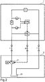
Fig. 2 is a schematic block diagram of an agricultural implement 1', which is supplied with hydraulic power via an LS system from atraction vehicle 2. -
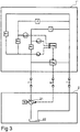
Fig. 3 is a schematic block diagram of an agricultural implement 1", which is supplied with hydraulic power via an LS system from atraction vehicle 2. -
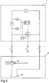
Fig. 4 is a schematic block diagram of an agricultural implement 1''', with functions corresponding to the ones shown infig. 2 which is supplied with hydraulic power via an LS system from atraction vehicle 2. -
Fig. 5 is a schematic block diagram of an agricultural implement 1IV with functions corresponding to the ones shown infig. 3 which is supplied with hydraulic power via an LS system from atraction vehicle 2. - In the following, components which are identical in the different drawings are designated with the same reference symbols throughout. For a description of the structure and functions of the
traction vehicle 2, reference to the description offig. 1 is made. - The agricultural implement 1, 1', 1" can be a soil-working agricultural implement such as a harrow, a plough, a cultivator and sowing machine or a combination thereof.
- With reference to
fig. 2 , the agricultural implement 1' comprises a load, which can be of a type such as described above. The agricultural implement 1' comprises a function valve FV, which can be of a type such as described above. - A first pressure sensor p_P for measuring a pressure upstream of the function valve FV is connected between the feed line P and function valve FV.
- A second pressure sensor p_L for measuring a pressure downstream of the function valve FV is connected between the function valve and load.
- The pressure sensors p_P, p_L can be of a type which provides a signal of discretionary type, e.g. electrical or hydraulic.
- The pressure sensors p_P, p_L are connected to a control unit LSreg which receives signals from the pressure sensors and brings about a control signal to a pressure regulating systemPreg.
- The control unit LSreg can be an electronic control unit which receives signals from the pressure sensors p_P, p_L, calculates a pressure difference Δp over the function valve FV and produces the control signal depending on the pressure difference Δp. Alternatively the control unit can be a fully or partially hydraulic or pneumatically activated control unit.
- According to one embodiment, the pressure sensors p_P, p_L can generate electrical signals to the control unit and the control unit LSreg can provide a hydraulic or electrical signal to the pressure regulating system Preg.
- According another embodiment, the pressure sensors p_P, p_L can generate hydraulic signals to the control unit and the control unit LSreg can provide a hydraulic or electrical signal to the pressure regulating system Preg.
- The pressure-regulating device Preg can be connected to the feed line P and/or to the return line T via respective valves (not shown) so that the pressure on the load-sensing line LS can be controlled freely based on the control signal from the control unit LSreg. The pressure-regulating device comprises a regulator which ensures that the correct pressure and/or flow is sent to internal regulators of the
pump 21 and can for example consist of a pressure-limiting valve or a pressure-reducing/relieving valve which hydraulically or electrically controlled. - With reference to
fig. 3 , an embodiment is shown in which the agricultural implement 1" has two function valves FV1, FV2 which each control a respective load L1, L2. - A first pressure sensor p_P is, as in
fig, 2 , connected between the feed line P and function valve FV for measuring a pressure upstream of the function valve FV. - A second pressure sensor p_L1 is connected between the first function valve and the first load L1 for measuring a pressure downstream of the function valve FV1.
- A third pressure sensor p_L2 is connected between the second function valve and the second load L2 for measuring a pressure downstream of the function valve FV2.
- All the pressure sensors p_P, p_L1, p_L2 are connected to the control unit LSreg which function in the same way as set out with reference to
fig. 2 . - The pressure-regulating device Preg in
fig. 3 also functions in the same way as set out with reference tofig. 2 . -
Fig. 3 also shows how an additional load Ext, which can be a function that does not require continuous LS regulation, such as a raising/lowering function of the agricultural implement, can be connected to the agricultural implement's hydraulic system. This further load EXT which is thus not controlled continuously like the other loads L1, L2, can temporarily require a greater pressure and/or load than that provided by continuous regulation via the control unit LSreg. - For example, activation of such an additional load can be combined with a signal to the control unit LSreg or to the pressure regulating device Preg, which results in a signal on the load-sensing line LS which brings about a temporary increase in pressure and/or flow on the feed line P.
- Such a signal can be produced during a predetermined period of time. Alternatively such a signal can be brought about continuously until a second signal is produced which makes the system return to normal pressure and/or flow. The signal can be based on information from the agricultural implement's overall control system, for example in connection with activation of the raising or lowering of tools etc.
- It can be seen that in a manner analogue to that shown in
fig. 3 any number of controlled or external loads can be added. - When two or more loads are present, the control unit LSreg and the pressure-regulating device Preg can take into consideration the load which requires the highest pressure and/or flow and control the pressure on the load-sensing line LS based on this.
-
Fig. 4 shows an embodiment corresponding to that infig. 2 but with one further function: a pressure sensor p_LS which is arranged to detect the pressure in the load-sensing line LS and to provide a corresponding signal to the control unit LSreg. The control unit LSreg can thus also produce the control signal to the pressure-regulating device based on the pressure measured in the load-sensing line LS. - Preferably the pressure sensor p_LS is set up to measure the pressure in the load-sensing line LS downstream of the pressure regulator and upstream of a coupling device for connecting to the
traction vehicle 2. - The control unit LSreg can determine whether the signal from the pressure sensor p_LS corresponds to the value set by the control unit.
- By also utilising a signal corresponding to the pressure in the load-sensing line LS, it is possible to ensure that a signal output on the load-sensing line LS is not affected by a pressure increase in the
pump 21 brought about through a changed condition on thetraction vehicle 2. - In this way a more stable signal can be produced on the load-sensing line which reduces the risk of unwanted fluctuations in pressure and/or flow in the system.
-
Fig. 5 shows an embodiment corresponding to that infig. 3 but with one further function: a pressure sensor p_LS which is arranged to detect the pressure in the load-sensing line LS and to provide a corresponding signal to the control unit LSreg in the same way was described with reference tofig. 4 . - It is also possible to utilise the pressure sensors p_LS on the load-sensing line LS in an embodiment without sensors p_L, p_L1, p_L2 for detecting a delta pressure, for example when there is only one external load Ext. In such a system the pressure sensor p_LS on the load-sensing line LS ensures that the correct signal is being sent to the pump through control in such a way that an expected value is received back. The pressure-regulator device Preg regulates the pressure based on the detected delta pressure and to achieve the desired pressure and/or flow. The signal for the desired value comes from the agricultural implement's overall control system, generated, for example, by an input from a user.
- As a further alternative the sensor p_P which measures the pressure in the feed line P can be discarded, whereby the pressure is only measured after the relevant function valve, i.e. p_L, p_L1, p_L2 and on the load-sensing line, at p_LS. This brings about measurement which is independent of the tractor's pump.
Claims (14)
- Agricultural implement (1', 1") which has at least one hydraulically activated function, supplied with hydraulic power via an LS system from a traction vehicle (2), said agricultural implement comprising:an incoming feed line (P) for hydraulic fluid,an outgoing return line (T) for the hydraulic fluid andan outgoing load-sensing line (LS),characterised bya sensor device (p_P, p_L, p_L1, p_L2, p_LS) for detecting a pressure in relation to the hydraulically activated function and/or in relation to the load-sensing line (LS),a regulating device (Preg) which is hydraulically connected to the load-sensing line (LS) and to at least one of the feed line (P) and return line (T), anda control unit (LSreg) which is arranged to receive a signal from the sensor device (p_P, p_L, p_L1, p_L2, p_LS) and to control the regulating device (Preg) to provide a predetermined pressure and/or flow on the load-sensing line (LS).
- Agricultural implement according to claim 1 also comprising at least one function valve (FV, FV1, FV2) which is connected to the feed line for operating a first load (L, L1, L2).
- Agricultural implement according to claim 2 wherein the sensor device comprises a first sensor (p_P) upstream of the function valve (FV, FV1, FV2) and a second sensor (p_L, p_L1, p_L2) downstream of the function valve (FV, FV1, FV2).
- Agricultural implement according to claim 2 or 3, wherein the sensor device (p_P, p_L, p_L1, p_L2) is set up to detect a pressure difference (Δp) over the function valve (FV, FV1, FV2), wherein the control system (LSreg) is set up to control said pressure and/or flow on the load-sensing line (LS) so that a predetermined pressure difference (Δp) is maintained.
- Agricultural implement according to any one of previous claims wherein the agricultural implement comprises an LS pressure sensor (p_LS) downstream of the regulator device (Preg) for detecting a pressure brought about in a load-sensing line (LS), and the control device (LSreg) is set up to control said pressure and/or flow on the load-sensing line so that a predetermined pressure and/or flow is brought about on the load-sensing line (LS).
- Agricultural implement according to any one of previous claims wherein at least one of said first and second sensors (p_P, p_L, p_L1, p_L2) is set up to send a hydraulic signal to the control unit (LSreg).
- Agricultural implement according to any one of claims 1-4 wherein at least one of said first and second sensors (p_P, p_L, p_L1, p_L2) is set up to send an electrical signal to the control unit (LSreg).
- Agricultural implement according to any one of previous claims wherein the regulating device (Preg) is connected to both the feed line (P) and the return line (T).
- Agricultural implement according to any one of previous claims wherein the control system (LSreg) is be set up to control the pressure and/or flow on the load-sensing line in order to provide a predetermined pressure in relation to the hydraulically activated function.
- Agricultural implement according to any one of previous claims, also comprising:a second hydraulically activated function anda second sensor device for detecting a second pressure in relation to the second hydraulically activated function,wherein the control unit (LSreg) is set up to receive a second signal from the second sensor device and to control the pressure and/or flow on the load-sensing line (LS) also based on the second signal.
- Method of supplying hydraulic power via an LS system, from a traction vehicle to an agricultural implement comprising:supplying via a feed line (P) pressurised hydraulic fluid to the agricultural implement (1', 1") from a hydraulic drive system (21) to at least one hydraulically activated function,returning the hydraulic fluid via a return line to the hydraulic drive system (21), andvia a load-sensing line (LS) returning a signal pressure for controlling the hydraulic drive system (21) and/or to a hydraulic fluid reservoir,characterised bymeasuring at least one pressure in relation to the hydraulically activated function andthrough a hydraulic connection between the feed line (P) and/or the return line (T) and load-sensing line (LS) controlling a pressure and/or flow on the load-sensing line (LS) based on the measured pressure.
- Method according to claim 11, also comprising
measuring a pressure difference (Δp) over a function valve (FV, FV1, FV2), and
controlling said pressure and/or flow on the load-sensing line (LS) based on the measured pressure difference (Δp). - Method according to claim 11 or 12, also comprising
measuring a pressure and/or flow on the load-sensing line (LS) and
controlling said pressure and/or flow on the load-sensing line (LS) so that a predetermined pressure and/or flow is brought about on the load-sensing line (LS). - Method according to any one of claims 11-13, also comprising:measuring a second pressure in relation to a second hydraulically operated function andcontrolling the pressure and/or flow on the load-sensing line (LS) based also on the second pressure.
Applications Claiming Priority (2)
| Application Number | Priority Date | Filing Date | Title |
|---|---|---|---|
| SE1550854A SE540462C2 (en) | 2015-06-18 | 2015-06-18 | Agricultural implements and method of feeding hydraulic power to an agricultural implement |
| PCT/SE2016/050587 WO2016204685A1 (en) | 2015-06-18 | 2016-06-16 | Agricultural implement and method of supplying hydraulic power to an agricultural implement |
Publications (2)
| Publication Number | Publication Date |
|---|---|
| EP3311035A1 EP3311035A1 (en) | 2018-04-25 |
| EP3311035B1 true EP3311035B1 (en) | 2020-07-22 |
Family
ID=56411863
Family Applications (1)
| Application Number | Title | Priority Date | Filing Date |
|---|---|---|---|
| EP16738892.5A Active EP3311035B1 (en) | 2015-06-18 | 2016-06-16 | Agricultural implement and method of supplying hydraulic power to an agricultural implement |
Country Status (3)
| Country | Link |
|---|---|
| EP (1) | EP3311035B1 (en) |
| SE (1) | SE540462C2 (en) |
| WO (1) | WO2016204685A1 (en) |
Families Citing this family (2)
| Publication number | Priority date | Publication date | Assignee | Title |
|---|---|---|---|---|
| SE2250604A1 (en) * | 2018-08-24 | 2022-05-19 | Brokk Ab | Demolition robot and method for feeding hydraulic power to a hydraulically driven tool at a demolition robot |
| US10912245B2 (en) * | 2018-12-14 | 2021-02-09 | Cnh Industrial America Llc | System and method for regulating the flow of fluid supplied to actuators of an agricultural implement |
Citations (2)
| Publication number | Priority date | Publication date | Assignee | Title |
|---|---|---|---|---|
| DE10308289A1 (en) | 2003-02-26 | 2004-09-09 | Bosch Rexroth Ag | LS-valve block control/drive method e.g. for work appliance such as farm tractor, requires operating electric control valve arrangements in relation to changed differential control pressure |
| EP2712502A1 (en) | 2012-09-28 | 2014-04-02 | Deere & Company | Trailed agricultural implement pump with hydraulic flow rate control |
Family Cites Families (4)
| Publication number | Priority date | Publication date | Assignee | Title |
|---|---|---|---|---|
| EP1338934A1 (en) * | 2002-02-26 | 2003-08-27 | Claas Saulgau Gmbh | Method for controlling an agricultural tractor with implement |
| DE202008007912U1 (en) * | 2008-05-09 | 2008-11-06 | Claas Saulgau Gmbh | Device for controlling mounted, towed or semi-mounted equipment as interchangeable equipment in connection with tractors |
| DE102012205940A1 (en) * | 2012-04-12 | 2013-10-17 | Robert Bosch Gmbh | Hydraulic system, method for controlling such a hydraulic system and mobile working machine with such a hydraulic system |
| US9618017B2 (en) * | 2012-04-17 | 2017-04-11 | Volvo Construction Equipment Ab | Hydraulic system for construction equipment |
-
2015
- 2015-06-18 SE SE1550854A patent/SE540462C2/en unknown
-
2016
- 2016-06-16 WO PCT/SE2016/050587 patent/WO2016204685A1/en not_active Ceased
- 2016-06-16 EP EP16738892.5A patent/EP3311035B1/en active Active
Patent Citations (2)
| Publication number | Priority date | Publication date | Assignee | Title |
|---|---|---|---|---|
| DE10308289A1 (en) | 2003-02-26 | 2004-09-09 | Bosch Rexroth Ag | LS-valve block control/drive method e.g. for work appliance such as farm tractor, requires operating electric control valve arrangements in relation to changed differential control pressure |
| EP2712502A1 (en) | 2012-09-28 | 2014-04-02 | Deere & Company | Trailed agricultural implement pump with hydraulic flow rate control |
Non-Patent Citations (1)
| Title |
|---|
| "8. Kolloquium Mobilhydraulik, Freundes- und Forderkreis des Instituts fur mo- bile Maschinen und Nutzfahrzeuge e.V.", October 2014, SHAKER VERLAG, ISBN: 978-3-8440-3082-2, article "8. Kolloquium Mobilhydraulik", pages: 8 - 25, XP055962349 |
Also Published As
| Publication number | Publication date |
|---|---|
| SE540462C2 (en) | 2018-09-18 |
| SE1550854A1 (en) | 2016-12-19 |
| WO2016204685A9 (en) | 2017-01-19 |
| EP3311035A1 (en) | 2018-04-25 |
| WO2016204685A1 (en) | 2016-12-22 |
Similar Documents
| Publication | Publication Date | Title |
|---|---|---|
| EP2676535B1 (en) | Position and pressure depth control system for an agricultural implement | |
| CN106930990B (en) | System for controlling the supply of hydraulic fluid to a work vehicle implement | |
| US11382258B1 (en) | Depth control for a seed planting system | |
| CA2866050C (en) | Agricultural implement actuator sensor protection | |
| RU2586156C2 (en) | System and method of determining position of tool for interaction with soil on basis of fluid pressure | |
| US8235130B2 (en) | Method and apparatus for controlling the depth of an agricultural work unit mounted to a frame that can be raised and lowered by a cylinder assembly | |
| US5152347A (en) | Interface system for a towed implement | |
| US11678597B2 (en) | Negative downforce system for ground engaging machinery | |
| US11229157B2 (en) | Independent planter closing system | |
| US20080257570A1 (en) | Electronic draft control for semi-trailed implements | |
| US20080257569A1 (en) | Electronic draft control for trailed implements | |
| EP3311035B1 (en) | Agricultural implement and method of supplying hydraulic power to an agricultural implement | |
| CN102588371A (en) | Valve control valve circuit for operating a single acting hydraulic cylinder | |
| US20180220574A1 (en) | Gauge wheel and hitch force control | |
| EP2886877B1 (en) | Power beyond valve assembly for an agricultural implement | |
| US10912245B2 (en) | System and method for regulating the flow of fluid supplied to actuators of an agricultural implement | |
| EP2934082B1 (en) | Method for controlling an agricultural implement, and agricultural implement | |
| SE540519C2 (en) | Procedure for the control of agricultural implements, as well as agricultural implements | |
| US20200214190A1 (en) | Agricultural machine and method for operating an agricultural machine | |
| CN109398338B (en) | Brake assist system and method for assisting steering operation of a moving vehicle | |
| KR102498279B1 (en) | Traction control hydraulic system for agricultural tractor and traction control method for agricultural tractor | |
| US20170241447A1 (en) | System and method for hydraulic flow control | |
| EP3321515A1 (en) | Hydraulic cylinder supply system | |
| US9462740B2 (en) | Long distance electronic load sense signal communication for implement control | |
| US20240306525A1 (en) | Down force control in an agricultural implement |
Legal Events
| Date | Code | Title | Description |
|---|---|---|---|
| STAA | Information on the status of an ep patent application or granted ep patent |
Free format text: STATUS: THE INTERNATIONAL PUBLICATION HAS BEEN MADE |
|
| PUAI | Public reference made under article 153(3) epc to a published international application that has entered the european phase |
Free format text: ORIGINAL CODE: 0009012 |
|
| STAA | Information on the status of an ep patent application or granted ep patent |
Free format text: STATUS: REQUEST FOR EXAMINATION WAS MADE |
|
| 17P | Request for examination filed |
Effective date: 20171219 |
|
| AK | Designated contracting states |
Kind code of ref document: A1 Designated state(s): AL AT BE BG CH CY CZ DE DK EE ES FI FR GB GR HR HU IE IS IT LI LT LU LV MC MK MT NL NO PL PT RO RS SE SI SK SM TR |
|
| AX | Request for extension of the european patent |
Extension state: BA ME |
|
| RIN1 | Information on inventor provided before grant (corrected) |
Inventor name: NILSSON, ANDERS Inventor name: SOEDERBERG, JOHAN |
|
| DAV | Request for validation of the european patent (deleted) | ||
| DAX | Request for extension of the european patent (deleted) | ||
| GRAP | Despatch of communication of intention to grant a patent |
Free format text: ORIGINAL CODE: EPIDOSNIGR1 |
|
| STAA | Information on the status of an ep patent application or granted ep patent |
Free format text: STATUS: GRANT OF PATENT IS INTENDED |
|
| RIC1 | Information provided on ipc code assigned before grant |
Ipc: A01B 63/112 20060101ALI20200108BHEP Ipc: A01B 63/10 20060101ALI20200108BHEP Ipc: F15B 11/16 20060101ALI20200108BHEP Ipc: A01B 63/32 20060101ALI20200108BHEP Ipc: A01B 63/22 20060101ALI20200108BHEP Ipc: F15B 11/05 20060101AFI20200108BHEP |
|
| INTG | Intention to grant announced |
Effective date: 20200203 |
|
| GRAS | Grant fee paid |
Free format text: ORIGINAL CODE: EPIDOSNIGR3 |
|
| GRAA | (expected) grant |
Free format text: ORIGINAL CODE: 0009210 |
|
| STAA | Information on the status of an ep patent application or granted ep patent |
Free format text: STATUS: THE PATENT HAS BEEN GRANTED |
|
| AK | Designated contracting states |
Kind code of ref document: B1 Designated state(s): AL AT BE BG CH CY CZ DE DK EE ES FI FR GB GR HR HU IE IS IT LI LT LU LV MC MK MT NL NO PL PT RO RS SE SI SK SM TR |
|
| REG | Reference to a national code |
Ref country code: GB Ref legal event code: FG4D |
|
| REG | Reference to a national code |
Ref country code: CH Ref legal event code: EP |
|
| REG | Reference to a national code |
Ref country code: DE Ref legal event code: R096 Ref document number: 602016040408 Country of ref document: DE |
|
| REG | Reference to a national code |
Ref country code: AT Ref legal event code: REF Ref document number: 1293651 Country of ref document: AT Kind code of ref document: T Effective date: 20200815 |
|
| REG | Reference to a national code |
Ref country code: IE Ref legal event code: FG4D |
|
| REG | Reference to a national code |
Ref country code: LT Ref legal event code: MG4D |
|
| REG | Reference to a national code |
Ref country code: AT Ref legal event code: MK05 Ref document number: 1293651 Country of ref document: AT Kind code of ref document: T Effective date: 20200722 |
|
| PG25 | Lapsed in a contracting state [announced via postgrant information from national office to epo] |
Ref country code: NO Free format text: LAPSE BECAUSE OF FAILURE TO SUBMIT A TRANSLATION OF THE DESCRIPTION OR TO PAY THE FEE WITHIN THE PRESCRIBED TIME-LIMIT Effective date: 20201022 Ref country code: GR Free format text: LAPSE BECAUSE OF FAILURE TO SUBMIT A TRANSLATION OF THE DESCRIPTION OR TO PAY THE FEE WITHIN THE PRESCRIBED TIME-LIMIT Effective date: 20201023 Ref country code: ES Free format text: LAPSE BECAUSE OF FAILURE TO SUBMIT A TRANSLATION OF THE DESCRIPTION OR TO PAY THE FEE WITHIN THE PRESCRIBED TIME-LIMIT Effective date: 20200722 Ref country code: SE Free format text: LAPSE BECAUSE OF FAILURE TO SUBMIT A TRANSLATION OF THE DESCRIPTION OR TO PAY THE FEE WITHIN THE PRESCRIBED TIME-LIMIT Effective date: 20200722 Ref country code: AT Free format text: LAPSE BECAUSE OF FAILURE TO SUBMIT A TRANSLATION OF THE DESCRIPTION OR TO PAY THE FEE WITHIN THE PRESCRIBED TIME-LIMIT Effective date: 20200722 Ref country code: HR Free format text: LAPSE BECAUSE OF FAILURE TO SUBMIT A TRANSLATION OF THE DESCRIPTION OR TO PAY THE FEE WITHIN THE PRESCRIBED TIME-LIMIT Effective date: 20200722 Ref country code: LT Free format text: LAPSE BECAUSE OF FAILURE TO SUBMIT A TRANSLATION OF THE DESCRIPTION OR TO PAY THE FEE WITHIN THE PRESCRIBED TIME-LIMIT Effective date: 20200722 Ref country code: BG Free format text: LAPSE BECAUSE OF FAILURE TO SUBMIT A TRANSLATION OF THE DESCRIPTION OR TO PAY THE FEE WITHIN THE PRESCRIBED TIME-LIMIT Effective date: 20201022 Ref country code: PT Free format text: LAPSE BECAUSE OF FAILURE TO SUBMIT A TRANSLATION OF THE DESCRIPTION OR TO PAY THE FEE WITHIN THE PRESCRIBED TIME-LIMIT Effective date: 20201123 Ref country code: FI Free format text: LAPSE BECAUSE OF FAILURE TO SUBMIT A TRANSLATION OF THE DESCRIPTION OR TO PAY THE FEE WITHIN THE PRESCRIBED TIME-LIMIT Effective date: 20200722 |
|
| PG25 | Lapsed in a contracting state [announced via postgrant information from national office to epo] |
Ref country code: LV Free format text: LAPSE BECAUSE OF FAILURE TO SUBMIT A TRANSLATION OF THE DESCRIPTION OR TO PAY THE FEE WITHIN THE PRESCRIBED TIME-LIMIT Effective date: 20200722 Ref country code: RS Free format text: LAPSE BECAUSE OF FAILURE TO SUBMIT A TRANSLATION OF THE DESCRIPTION OR TO PAY THE FEE WITHIN THE PRESCRIBED TIME-LIMIT Effective date: 20200722 Ref country code: PL Free format text: LAPSE BECAUSE OF FAILURE TO SUBMIT A TRANSLATION OF THE DESCRIPTION OR TO PAY THE FEE WITHIN THE PRESCRIBED TIME-LIMIT Effective date: 20200722 Ref country code: IS Free format text: LAPSE BECAUSE OF FAILURE TO SUBMIT A TRANSLATION OF THE DESCRIPTION OR TO PAY THE FEE WITHIN THE PRESCRIBED TIME-LIMIT Effective date: 20201122 |
|
| PG25 | Lapsed in a contracting state [announced via postgrant information from national office to epo] |
Ref country code: NL Free format text: LAPSE BECAUSE OF FAILURE TO SUBMIT A TRANSLATION OF THE DESCRIPTION OR TO PAY THE FEE WITHIN THE PRESCRIBED TIME-LIMIT Effective date: 20200722 |
|
| REG | Reference to a national code |
Ref country code: DE Ref legal event code: R026 Ref document number: 602016040408 Country of ref document: DE |
|
| PLBI | Opposition filed |
Free format text: ORIGINAL CODE: 0009260 |
|
| PG25 | Lapsed in a contracting state [announced via postgrant information from national office to epo] |
Ref country code: IT Free format text: LAPSE BECAUSE OF FAILURE TO SUBMIT A TRANSLATION OF THE DESCRIPTION OR TO PAY THE FEE WITHIN THE PRESCRIBED TIME-LIMIT Effective date: 20200722 Ref country code: EE Free format text: LAPSE BECAUSE OF FAILURE TO SUBMIT A TRANSLATION OF THE DESCRIPTION OR TO PAY THE FEE WITHIN THE PRESCRIBED TIME-LIMIT Effective date: 20200722 Ref country code: DK Free format text: LAPSE BECAUSE OF FAILURE TO SUBMIT A TRANSLATION OF THE DESCRIPTION OR TO PAY THE FEE WITHIN THE PRESCRIBED TIME-LIMIT Effective date: 20200722 Ref country code: CZ Free format text: LAPSE BECAUSE OF FAILURE TO SUBMIT A TRANSLATION OF THE DESCRIPTION OR TO PAY THE FEE WITHIN THE PRESCRIBED TIME-LIMIT Effective date: 20200722 Ref country code: SM Free format text: LAPSE BECAUSE OF FAILURE TO SUBMIT A TRANSLATION OF THE DESCRIPTION OR TO PAY THE FEE WITHIN THE PRESCRIBED TIME-LIMIT Effective date: 20200722 Ref country code: RO Free format text: LAPSE BECAUSE OF FAILURE TO SUBMIT A TRANSLATION OF THE DESCRIPTION OR TO PAY THE FEE WITHIN THE PRESCRIBED TIME-LIMIT Effective date: 20200722 |
|
| PLAX | Notice of opposition and request to file observation + time limit sent |
Free format text: ORIGINAL CODE: EPIDOSNOBS2 |
|
| 26 | Opposition filed |
Opponent name: AMAZONEN-WERKE H. DREYER GMBH & CO. KG Effective date: 20210421 |
|
| REG | Reference to a national code |
Ref country code: NL Ref legal event code: MP Effective date: 20200722 |
|
| PG25 | Lapsed in a contracting state [announced via postgrant information from national office to epo] |
Ref country code: AL Free format text: LAPSE BECAUSE OF FAILURE TO SUBMIT A TRANSLATION OF THE DESCRIPTION OR TO PAY THE FEE WITHIN THE PRESCRIBED TIME-LIMIT Effective date: 20200722 |
|
| PG25 | Lapsed in a contracting state [announced via postgrant information from national office to epo] |
Ref country code: SK Free format text: LAPSE BECAUSE OF FAILURE TO SUBMIT A TRANSLATION OF THE DESCRIPTION OR TO PAY THE FEE WITHIN THE PRESCRIBED TIME-LIMIT Effective date: 20200722 |
|
| PG25 | Lapsed in a contracting state [announced via postgrant information from national office to epo] |
Ref country code: SI Free format text: LAPSE BECAUSE OF FAILURE TO SUBMIT A TRANSLATION OF THE DESCRIPTION OR TO PAY THE FEE WITHIN THE PRESCRIBED TIME-LIMIT Effective date: 20200722 |
|
| PLBB | Reply of patent proprietor to notice(s) of opposition received |
Free format text: ORIGINAL CODE: EPIDOSNOBS3 |
|
| PG25 | Lapsed in a contracting state [announced via postgrant information from national office to epo] |
Ref country code: MC Free format text: LAPSE BECAUSE OF FAILURE TO SUBMIT A TRANSLATION OF THE DESCRIPTION OR TO PAY THE FEE WITHIN THE PRESCRIBED TIME-LIMIT Effective date: 20200722 |
|
| REG | Reference to a national code |
Ref country code: CH Ref legal event code: PL |
|
| REG | Reference to a national code |
Ref country code: BE Ref legal event code: MM Effective date: 20210630 |
|
| PG25 | Lapsed in a contracting state [announced via postgrant information from national office to epo] |
Ref country code: LU Free format text: LAPSE BECAUSE OF NON-PAYMENT OF DUE FEES Effective date: 20210616 |
|
| PG25 | Lapsed in a contracting state [announced via postgrant information from national office to epo] |
Ref country code: LI Free format text: LAPSE BECAUSE OF NON-PAYMENT OF DUE FEES Effective date: 20210630 Ref country code: IE Free format text: LAPSE BECAUSE OF NON-PAYMENT OF DUE FEES Effective date: 20210616 Ref country code: CH Free format text: LAPSE BECAUSE OF NON-PAYMENT OF DUE FEES Effective date: 20210630 |
|
| REG | Reference to a national code |
Ref country code: DE Ref legal event code: R100 Ref document number: 602016040408 Country of ref document: DE |
|
| PLBD | Termination of opposition procedure: decision despatched |
Free format text: ORIGINAL CODE: EPIDOSNOPC1 |
|
| PLBP | Opposition withdrawn |
Free format text: ORIGINAL CODE: 0009264 |
|
| PG25 | Lapsed in a contracting state [announced via postgrant information from national office to epo] |
Ref country code: BE Free format text: LAPSE BECAUSE OF NON-PAYMENT OF DUE FEES Effective date: 20210630 |
|
| PLBM | Termination of opposition procedure: date of legal effect published |
Free format text: ORIGINAL CODE: 0009276 |
|
| 27C | Opposition proceedings terminated |
Effective date: 20220524 |
|
| P01 | Opt-out of the competence of the unified patent court (upc) registered |
Effective date: 20230523 |
|
| PG25 | Lapsed in a contracting state [announced via postgrant information from national office to epo] |
Ref country code: CY Free format text: LAPSE BECAUSE OF FAILURE TO SUBMIT A TRANSLATION OF THE DESCRIPTION OR TO PAY THE FEE WITHIN THE PRESCRIBED TIME-LIMIT Effective date: 20200722 |
|
| PG25 | Lapsed in a contracting state [announced via postgrant information from national office to epo] |
Ref country code: HU Free format text: LAPSE BECAUSE OF FAILURE TO SUBMIT A TRANSLATION OF THE DESCRIPTION OR TO PAY THE FEE WITHIN THE PRESCRIBED TIME-LIMIT; INVALID AB INITIO Effective date: 20160616 |
|
| PG25 | Lapsed in a contracting state [announced via postgrant information from national office to epo] |
Ref country code: MK Free format text: LAPSE BECAUSE OF FAILURE TO SUBMIT A TRANSLATION OF THE DESCRIPTION OR TO PAY THE FEE WITHIN THE PRESCRIBED TIME-LIMIT Effective date: 20200722 |
|
| PG25 | Lapsed in a contracting state [announced via postgrant information from national office to epo] |
Ref country code: MT Free format text: LAPSE BECAUSE OF FAILURE TO SUBMIT A TRANSLATION OF THE DESCRIPTION OR TO PAY THE FEE WITHIN THE PRESCRIBED TIME-LIMIT Effective date: 20200722 |
|
| PGFP | Annual fee paid to national office [announced via postgrant information from national office to epo] |
Ref country code: DE Payment date: 20250507 Year of fee payment: 10 |
|
| PGFP | Annual fee paid to national office [announced via postgrant information from national office to epo] |
Ref country code: GB Payment date: 20250501 Year of fee payment: 10 |
|
| PGFP | Annual fee paid to national office [announced via postgrant information from national office to epo] |
Ref country code: FR Payment date: 20250523 Year of fee payment: 10 |
|
| PG25 | Lapsed in a contracting state [announced via postgrant information from national office to epo] |
Ref country code: TR Free format text: LAPSE BECAUSE OF FAILURE TO SUBMIT A TRANSLATION OF THE DESCRIPTION OR TO PAY THE FEE WITHIN THE PRESCRIBED TIME-LIMIT Effective date: 20200722 |