EP3310409B1 - Occlusion detection techniques for a fluid infusion device having a rotary pump mechanism - Google Patents
Occlusion detection techniques for a fluid infusion device having a rotary pump mechanism Download PDFInfo
- Publication number
- EP3310409B1 EP3310409B1 EP16728196.3A EP16728196A EP3310409B1 EP 3310409 B1 EP3310409 B1 EP 3310409B1 EP 16728196 A EP16728196 A EP 16728196A EP 3310409 B1 EP3310409 B1 EP 3310409B1
- Authority
- EP
- European Patent Office
- Prior art keywords
- rotor
- fluid
- stator
- pump mechanism
- sensor
- Prior art date
- Legal status (The legal status is an assumption and is not a legal conclusion. Google has not performed a legal analysis and makes no representation as to the accuracy of the status listed.)
- Active
Links
- 239000012530 fluid Substances 0.000 title claims description 891
- 238000001514 detection method Methods 0.000 title description 317
- 230000007246 mechanism Effects 0.000 title description 258
- 238000001802 infusion Methods 0.000 title description 140
- 229940079593 drug Drugs 0.000 claims description 63
- 239000003814 drug Substances 0.000 claims description 63
- 239000004020 conductor Substances 0.000 claims description 8
- 238000000034 method Methods 0.000 description 107
- 230000006870 function Effects 0.000 description 75
- 238000011144 upstream manufacturing Methods 0.000 description 71
- 238000006073 displacement reaction Methods 0.000 description 51
- 238000010586 diagram Methods 0.000 description 44
- 230000003287 optical effect Effects 0.000 description 40
- 238000005086 pumping Methods 0.000 description 39
- 230000004044 response Effects 0.000 description 30
- 238000007920 subcutaneous administration Methods 0.000 description 29
- 238000003780 insertion Methods 0.000 description 27
- 230000037431 insertion Effects 0.000 description 27
- NOESYZHRGYRDHS-UHFFFAOYSA-N insulin Chemical compound N1C(=O)C(NC(=O)C(CCC(N)=O)NC(=O)C(CCC(O)=O)NC(=O)C(C(C)C)NC(=O)C(NC(=O)CN)C(C)CC)CSSCC(C(NC(CO)C(=O)NC(CC(C)C)C(=O)NC(CC=2C=CC(O)=CC=2)C(=O)NC(CCC(N)=O)C(=O)NC(CC(C)C)C(=O)NC(CCC(O)=O)C(=O)NC(CC(N)=O)C(=O)NC(CC=2C=CC(O)=CC=2)C(=O)NC(CSSCC(NC(=O)C(C(C)C)NC(=O)C(CC(C)C)NC(=O)C(CC=2C=CC(O)=CC=2)NC(=O)C(CC(C)C)NC(=O)C(C)NC(=O)C(CCC(O)=O)NC(=O)C(C(C)C)NC(=O)C(CC(C)C)NC(=O)C(CC=2NC=NC=2)NC(=O)C(CO)NC(=O)CNC2=O)C(=O)NCC(=O)NC(CCC(O)=O)C(=O)NC(CCCNC(N)=N)C(=O)NCC(=O)NC(CC=3C=CC=CC=3)C(=O)NC(CC=3C=CC=CC=3)C(=O)NC(CC=3C=CC(O)=CC=3)C(=O)NC(C(C)O)C(=O)N3C(CCC3)C(=O)NC(CCCCN)C(=O)NC(C)C(O)=O)C(=O)NC(CC(N)=O)C(O)=O)=O)NC(=O)C(C(C)CC)NC(=O)C(CO)NC(=O)C(C(C)O)NC(=O)C1CSSCC2NC(=O)C(CC(C)C)NC(=O)C(NC(=O)C(CCC(N)=O)NC(=O)C(CC(N)=O)NC(=O)C(NC(=O)C(N)CC=1C=CC=CC=1)C(C)C)CC1=CN=CN1 NOESYZHRGYRDHS-UHFFFAOYSA-N 0.000 description 24
- 230000009471 action Effects 0.000 description 21
- 238000004891 communication Methods 0.000 description 20
- 238000005259 measurement Methods 0.000 description 19
- 229920001746 electroactive polymer Polymers 0.000 description 18
- 230000000630 rising effect Effects 0.000 description 18
- 238000005516 engineering process Methods 0.000 description 17
- 230000033001 locomotion Effects 0.000 description 16
- 230000005291 magnetic effect Effects 0.000 description 13
- 238000007789 sealing Methods 0.000 description 13
- 102000004877 Insulin Human genes 0.000 description 12
- 108090001061 Insulin Proteins 0.000 description 12
- 229940125396 insulin Drugs 0.000 description 12
- 230000008569 process Effects 0.000 description 11
- 239000000853 adhesive Substances 0.000 description 10
- 230000001070 adhesive effect Effects 0.000 description 10
- 230000000875 corresponding effect Effects 0.000 description 10
- 230000005284 excitation Effects 0.000 description 9
- 238000002560 therapeutic procedure Methods 0.000 description 9
- 230000006399 behavior Effects 0.000 description 7
- 230000001939 inductive effect Effects 0.000 description 7
- 238000012545 processing Methods 0.000 description 7
- 230000001133 acceleration Effects 0.000 description 6
- 230000008602 contraction Effects 0.000 description 6
- 239000000463 material Substances 0.000 description 6
- 208000034423 Delivery Diseases 0.000 description 5
- 230000008878 coupling Effects 0.000 description 5
- 238000010168 coupling process Methods 0.000 description 5
- 238000005859 coupling reaction Methods 0.000 description 5
- 230000007423 decrease Effects 0.000 description 5
- 238000013461 design Methods 0.000 description 5
- 238000009434 installation Methods 0.000 description 5
- 230000006835 compression Effects 0.000 description 4
- 238000007906 compression Methods 0.000 description 4
- 230000003993 interaction Effects 0.000 description 4
- 230000014759 maintenance of location Effects 0.000 description 4
- 238000012544 monitoring process Methods 0.000 description 4
- 230000004913 activation Effects 0.000 description 3
- 238000004458 analytical method Methods 0.000 description 3
- 239000003990 capacitor Substances 0.000 description 3
- 238000012790 confirmation Methods 0.000 description 3
- 230000002596 correlated effect Effects 0.000 description 3
- 206010012601 diabetes mellitus Diseases 0.000 description 3
- 239000013536 elastomeric material Substances 0.000 description 3
- 230000000977 initiatory effect Effects 0.000 description 3
- 230000000670 limiting effect Effects 0.000 description 3
- 239000007788 liquid Substances 0.000 description 3
- 230000037361 pathway Effects 0.000 description 3
- XEEYBQQBJWHFJM-UHFFFAOYSA-N Iron Chemical compound [Fe] XEEYBQQBJWHFJM-UHFFFAOYSA-N 0.000 description 2
- HZEWFHLRYVTOIW-UHFFFAOYSA-N [Ti].[Ni] Chemical compound [Ti].[Ni] HZEWFHLRYVTOIW-UHFFFAOYSA-N 0.000 description 2
- 238000009530 blood pressure measurement Methods 0.000 description 2
- 230000008859 change Effects 0.000 description 2
- 201000010099 disease Diseases 0.000 description 2
- 208000037265 diseases, disorders, signs and symptoms Diseases 0.000 description 2
- 239000010408 film Substances 0.000 description 2
- 238000003384 imaging method Methods 0.000 description 2
- 230000001976 improved effect Effects 0.000 description 2
- 238000004519 manufacturing process Methods 0.000 description 2
- 229910052751 metal Inorganic materials 0.000 description 2
- 239000002184 metal Substances 0.000 description 2
- 229910001000 nickel titanium Inorganic materials 0.000 description 2
- 230000002441 reversible effect Effects 0.000 description 2
- 239000007787 solid Substances 0.000 description 2
- 239000000126 substance Substances 0.000 description 2
- 239000010409 thin film Substances 0.000 description 2
- 230000001960 triggered effect Effects 0.000 description 2
- 238000002604 ultrasonography Methods 0.000 description 2
- 241001631457 Cannula Species 0.000 description 1
- 229910000831 Steel Inorganic materials 0.000 description 1
- 230000003213 activating effect Effects 0.000 description 1
- 239000002390 adhesive tape Substances 0.000 description 1
- 230000002411 adverse Effects 0.000 description 1
- 239000003570 air Substances 0.000 description 1
- 238000011394 anticancer treatment Methods 0.000 description 1
- 238000013459 approach Methods 0.000 description 1
- 238000000418 atomic force spectrum Methods 0.000 description 1
- 230000005540 biological transmission Effects 0.000 description 1
- 230000009920 chelation Effects 0.000 description 1
- 238000006243 chemical reaction Methods 0.000 description 1
- 239000000356 contaminant Substances 0.000 description 1
- 230000001934 delay Effects 0.000 description 1
- 230000000694 effects Effects 0.000 description 1
- 230000005611 electricity Effects 0.000 description 1
- 230000005294 ferromagnetic effect Effects 0.000 description 1
- 239000003302 ferromagnetic material Substances 0.000 description 1
- 239000011521 glass Substances 0.000 description 1
- 230000036541 health Effects 0.000 description 1
- 229940088597 hormone Drugs 0.000 description 1
- 239000005556 hormone Substances 0.000 description 1
- 230000002209 hydrophobic effect Effects 0.000 description 1
- 230000003116 impacting effect Effects 0.000 description 1
- 230000008676 import Effects 0.000 description 1
- 238000007373 indentation Methods 0.000 description 1
- 229910052742 iron Inorganic materials 0.000 description 1
- 238000007726 management method Methods 0.000 description 1
- 238000002483 medication Methods 0.000 description 1
- 239000012528 membrane Substances 0.000 description 1
- 239000002991 molded plastic Substances 0.000 description 1
- 238000012634 optical imaging Methods 0.000 description 1
- 125000002524 organometallic group Chemical group 0.000 description 1
- 229940124583 pain medication Drugs 0.000 description 1
- 230000002093 peripheral effect Effects 0.000 description 1
- 239000004033 plastic Substances 0.000 description 1
- 238000007747 plating Methods 0.000 description 1
- 229920000642 polymer Polymers 0.000 description 1
- 238000003825 pressing Methods 0.000 description 1
- 230000037452 priming Effects 0.000 description 1
- 208000002815 pulmonary hypertension Diseases 0.000 description 1
- 238000011084 recovery Methods 0.000 description 1
- 238000011160 research Methods 0.000 description 1
- 230000000284 resting effect Effects 0.000 description 1
- 238000005070 sampling Methods 0.000 description 1
- 239000004065 semiconductor Substances 0.000 description 1
- 238000001228 spectrum Methods 0.000 description 1
- 229910001220 stainless steel Inorganic materials 0.000 description 1
- 239000010935 stainless steel Substances 0.000 description 1
- 230000003068 static effect Effects 0.000 description 1
- 239000010959 steel Substances 0.000 description 1
- 238000003860 storage Methods 0.000 description 1
- 230000008093 supporting effect Effects 0.000 description 1
- 238000012546 transfer Methods 0.000 description 1
- 238000013519 translation Methods 0.000 description 1
- 238000011282 treatment Methods 0.000 description 1
- 229940088594 vitamin Drugs 0.000 description 1
- 239000011782 vitamin Substances 0.000 description 1
- 229930003231 vitamin Natural products 0.000 description 1
- 235000013343 vitamin Nutrition 0.000 description 1
- 230000002618 waking effect Effects 0.000 description 1
- XLYOFNOQVPJJNP-UHFFFAOYSA-N water Substances O XLYOFNOQVPJJNP-UHFFFAOYSA-N 0.000 description 1
- 238000004804 winding Methods 0.000 description 1
Images


Classifications
-
- A—HUMAN NECESSITIES
- A61—MEDICAL OR VETERINARY SCIENCE; HYGIENE
- A61M—DEVICES FOR INTRODUCING MEDIA INTO, OR ONTO, THE BODY; DEVICES FOR TRANSDUCING BODY MEDIA OR FOR TAKING MEDIA FROM THE BODY; DEVICES FOR PRODUCING OR ENDING SLEEP OR STUPOR
- A61M5/00—Devices for bringing media into the body in a subcutaneous, intra-vascular or intramuscular way; Accessories therefor, e.g. filling or cleaning devices, arm-rests
- A61M5/14—Infusion devices, e.g. infusing by gravity; Blood infusion; Accessories therefor
- A61M5/142—Pressure infusion, e.g. using pumps
- A61M5/14212—Pumping with an aspiration and an expulsion action
- A61M5/14216—Reciprocating piston type
-
- A—HUMAN NECESSITIES
- A61—MEDICAL OR VETERINARY SCIENCE; HYGIENE
- A61M—DEVICES FOR INTRODUCING MEDIA INTO, OR ONTO, THE BODY; DEVICES FOR TRANSDUCING BODY MEDIA OR FOR TAKING MEDIA FROM THE BODY; DEVICES FOR PRODUCING OR ENDING SLEEP OR STUPOR
- A61M5/00—Devices for bringing media into the body in a subcutaneous, intra-vascular or intramuscular way; Accessories therefor, e.g. filling or cleaning devices, arm-rests
- A61M5/14—Infusion devices, e.g. infusing by gravity; Blood infusion; Accessories therefor
- A61M5/168—Means for controlling media flow to the body or for metering media to the body, e.g. drip meters, counters ; Monitoring media flow to the body
- A61M5/16831—Monitoring, detecting, signalling or eliminating infusion flow anomalies
- A61M2005/16863—Occlusion detection
Definitions
- Embodiments of the subject matter described herein relate generally to fluid infusion devices of the type suitable for delivering a medication fluid to the body of a patient. More particularly, embodiments of the subject matter presented herein relate to techniques for detecting an occlusion in the fluid delivery path of a fluid infusion device having a rotary pump mechanism.
- An exemplary medication fluid is insulin used in the management of diabetes.
- Certain diseases or conditions may be treated, according to modem medical techniques, by delivering a medication fluid or other substance to the body of a patient, either in a continuous manner or at particular times or time intervals within an overall time period.
- a medication fluid or other substance for example, diabetes is commonly treated by delivering defined amounts of insulin to the patient at appropriate times.
- Some common modes of providing insulin therapy to a patient include delivery of insulin through manually operated syringes and insulin pens.
- Other modern systems employ programmable fluid infusion devices (e.g., insulin pumps) to deliver controlled amounts of insulin to a patient.
- a fluid infusion device suitable for use as an insulin pump may be realized as an external device or an implantable device, which is surgically implanted into the body of the patient.
- External fluid infusion devices include devices designed for use in a generally stationary location (for example, in a hospital or clinic bedside environment), and devices configured for ambulatory or portable use (to be carried or worn by a patient).
- External fluid infusion devices may establish a fluid flow path from a fluid reservoir or cartridge to the patient via, for example, a suitable hollow tubing, needle, or other type of fluid conduit.
- a fluid infusion device can be implemented with a rotary micropump mechanism that accurately delivers a precise volume of fluid with each revolution or cycle.
- the inlet of the micropump is connected to a fluid source such as a reservoir, and the outlet of the micropump is connected to a fluid delivery conduit that leads to the body of the patient.
- the micropump draws fluid from the fluid source (via a vacuum or suction action) and then delivers a predictable volume of fluid with each cycle.
- a sensing element terminates at or near the stator cam surface.
- the sensing element cooperates with a detection circuit to detect whether or not the stator cam surface is in contact with the sensor contact element.
- the detection circuit monitors characteristics of a detection signal obtained from the sensing element in response to angular position of the rotor to determine an operating condition of the fluid pump mechanism.
- the fluid pump mechanism includes: a stator; a rotor; an inlet valve that opens and closes as a function of angular and axial position of the rotor; an outlet valve that opens and closes as a function of angular and axial position of the rotor; a sensor contact element; and a sensing element.
- the stator cam element has a stator cam surface, and the rotor includes a reference surface and a rotor cam element having a variable height rising from the reference surface. The rotor cam element cooperates with the stator cam element to axially displace the rotor, relative to the stator, as a function of angular position of the rotor.
- the sensor contact element resides on the reference surface in an area corresponding to a valve state in which the inlet valve is closed and the outlet valve is open.
- the sensing element terminates at or near the stator cam surface, and it cooperates with a detection circuit to detect whether or not the stator cam surface is in contact with the sensor contact element.
- the detection circuit monitors characteristics of a detection signal obtained from the sensing element in response to angular position of the rotor to determine an operating condition of the fluid pump mechanism.
- the fluid pump mechanism includes a stator with a stator cam element having a stator cam surface.
- the fluid pump mechanism also includes a rotor with a reference surface and a rotor cam element having a variable height rising from the reference surface.
- the rotor cam element cooperates with the stator cam element to axially displace the rotor, relative to the stator, as a function of angular position of the rotor.
- a biasing element provides a biasing force to urge the rotor cam element toward the stator cam element and toward the reference surface.
- a force sensor is coupled to the rotor. The force sensor generates output levels in response to force imparted thereto, and the force sensor cooperates with a detection circuit that obtains and processes the output levels to detect occlusions in a fluid path downstream of the fluid pump mechanism.
- a fluid pump mechanism includes a stator with a stator cam element having a stator cam surface, and a rotor with an optically detectable feature, a reference surface, and a rotor cam element having a variable height rising from the reference surface.
- the rotor cam element cooperates with the stator cam element to axially displace the rotor, relative to the stator, as a function of angular position of the rotor.
- the optically detectable feature rotates and axially translates as a function of angular position of the rotor.
- An optical detection circuit interrogates the optically detectable feature during operation of the fluid pump mechanism to determine an operating condition of the fluid pump mechanism.
- An exemplary embodiment of a fluid infusion device includes: a fluid pump mechanism; a biasing element; a subcutaneous conduit; a drive motor; and a detection circuit.
- the fluid pump mechanism cooperates with a fluid cartridge module, and the fluid pump mechanism includes a rotor and a stator.
- the rotor includes a reference surface and a rotor cam element having a variable height rising from the reference surface, and the stator includes a stator cam element having a stator cam surface.
- the rotor cam element cooperates with the stator cam element to axially displace the rotor, relative to the stator, as a function of angular position of the rotor.
- An exemplary embodiment of a fluid infusion device includes a fluid pump mechanism that cooperates with a fluid cartridge module.
- the fluid pump mechanism includes a rotor and a stator; the rotor has a reference surface and a rotor cam element having a variable height rising from the reference surface.
- the stator includes a stator cam element having a stator cam surface, wherein the rotor cam element cooperates with the stator cam element to axially displace the rotor, relative to the stator, as a function of angular position of the rotor.
- An exemplary embodiment of a fluid pump mechanism includes a stator with a stator cam element having a stator cam surface.
- the fluid pump mechanism also includes a rotor having: an endcap with a rim; a reference surface located inside the endcap; and a rotor cam element located inside the endcap and having a variable height rising from the reference surface.
- the rotor cam element cooperates with the stator cam element to axially displace the rotor, relative to the stator, as a function of angular position of the rotor.
- a first sensor contact element resides on the rim of the endcap, and is located at an angular position that follows an upper edge of the rotor cam element.
- the pump includes a stator, a rotationally drivable rotor disposed in the stator and axially movable between a retracted position and an extended position, a cam arrangement disposed between the rotor and the stator to apply a force to urge the rotor towards the extended position during a first part of the rotation of the rotor then remove the force on further rotation in each of repeated pump cycles, and a biasing element positioned to urge the rotor back towards the retracted position.
- the pump has a stator, a rotationally drivable rotor disposed in the stator and axially movable between a retracted position and an extended position, a cam arrangement disposed between the rotor and the stator to apply a force to urge the rotor towards the extended position during a first part of the rotation of the rotor then remove the force on further rotation in each of repeated pump cycles, and a biasing element positioned to urge the rotor back towards the retracted position.
- Also presented herein is an exemplary embodiment of a method of detecting occlusion in a pump for medication fluid of the type having a rotationally drivable rotor disposed in a stator and axially movable between a retracted position and an extended position, having a cam arrangement disposed between the rotor and the stator to apply a force in each of repeated pump cycles to urge the rotor towards the extended position during a first part of the rotation of the rotor then remove the force on further rotation, there being a biasing element positioned to urge the rotor back towards the retracted position, and having valving responsive to the angular position of the rotor including an inlet valve configured to open during a first arc of rotation for which the cam arrangement applies the force to the rotor and an outlet valve configured to open for a second arc of rotation after the force has been removed.
- Also presented herein is another embodiment of a method of detecting occlusion in a pump for medication fluid of the type having a rotationally drivable rotor disposed in a stator and axially movable between a retracted position and an extended position, having a cam arrangement disposed between the rotor and the stator to apply a force in each of repeated pump cycles to urge the rotor towards the extended position during a first part of the angular rotation of the rotor then remove the force on further rotation, there being a biasing element positioned to urge the rotor back towards the retracted position, and having valving responsive to the angular position of the rotor including an inlet valve configured to open during a first arc of rotation for which the cam arrangement applies the force to the rotor and an outlet valve configured to open for a second arc of rotation after the force has been removed.
- the following description relates to a fluid infusion device of the type used to treat a medical condition of a patient.
- the infusion device is used for infusing fluid (such as a medication) into the body of a user.
- fluid such as a medication
- the non-limiting examples described below relate to a medical device used to treat diabetes (more specifically, an insulin infusion device), although embodiments of the disclosed subject matter are not so limited.
- the infused medication fluid is insulin in certain embodiments.
- many other fluids may be administered through infusion such as, but not limited to, disease treatments, drugs to treat pulmonary hypertension, iron chelation drugs, pain medications, anti-cancer treatments, medications, vitamins, hormones, or the like.
- conventional features and characteristics related to infusion system operation, insulin pump operation, fluid reservoirs, and fluid conduits such as soft cannulas may not be described in detail here.
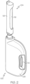
- the fluid infusion device 100 includes a housing 106 that serves as a shell for a variety of internal components.
- the housing 106 is suitably configured to receive, secure, and release the removable fluid cartridge module 104.
- the fluid cartridge module 104 can be received in a suitably shaped, sized, and configured cavity that is designed in accordance with certain physical characteristics of the fluid cartridge module 104.
- the housing 106 can include structural features that mate with or otherwise engage structural features of the fluid cartridge module 104.
- the illustrated embodiment of the removable fluid cartridge module 104 includes a retention mechanism 110 that secures the fluid cartridge module 104 in the properly installed and seated position within the fluid infusion device 100.
- the fluid infusion device 100 includes at least one user interface feature, which can be actuated by the patient as needed.
- the illustrated embodiment of the fluid infusion device 100 includes a button 112 that is physically actuated.
- the button 112 can be a multipurpose user interface if so desired to make it easier for the user to operate the fluid infusion device 100.
- the button 112 can be used in connection with one or more of the following functions, without limitation: waking up the processor and/or electronics of the fluid infusion device 100; triggering an insertion mechanism for actuating a transcutaneous conduit assembly (e.g., inserting a cannula into the subcutaneous space, or similar region of the patient); configuring one or more settings of the fluid infusion device 100; initiating delivery of medication fluid; initiating a fluid priming operation; disabling alerts or alarms generated by the fluid infusion device 100; and the like.
- the fluid infusion device 100 can employ a slider mechanism, a pin, a lever, or the like.
- the fluid infusion device 100 includes an adhesive element or adhesive material (hidden from view in FIG. 1 and FIG. 2 ) that can be used to affix the housing 106 to the body of the patient.
- the adhesive element can be located on the bottom surface of the housing 106 such that the housing 106 can be temporarily adhered to the skin of the patient.
- the adhesive element may be, for example, a piece of double sided adhesive tape that is cut into the desired shape and size.
- the fluid infusion device 100 is manufactured with an adhesive liner overlying the adhesive element; the adhesive liner is peeled away to expose the sticky surface of the adhesive element 114.
- the adhesive element is chosen to be strong enough to maintain the fluid infusion device 100 in place for the desired period of time (which is typically between one to seven days) and strong enough to withstand typical use cases (e.g., showering, rainy days, physical exercise, etc.), while also being easy to remove without discomfort.
- the fluid infusion device 100 is deployed in the following manner: (1) insert the fluid cartridge module 104 into the housing 106; (2) remove the adhesive liner; (3) affix the housing 106 to the body; and (4) insert the fluid delivery cannula into the body by pressing a button, pulling a tab, removing a safety pin, or otherwise activating an insertion mechanism to release a preloaded spring or equivalent actuation component. Thereafter, the fluid infusion device can be prepared for the delivery of the medication fluid as needed.
- the fluid cartridge module 104 is installed after the housing 106 is affixed to the body.
- the action of installing the fluid cartridge module 104 into the housing 106 engages or moves a mechanical, electrical, magnetic, or other type of interface, which in turn releases a preloaded spring or equivalent actuation component to insert the fluid delivery cannula into the body.
- the spring is released upon the first cartridge insertion, the fluid infusion device 100 is put into a different state such that subsequent installations of a fluid cartridge module will not trigger the insertion mechanism again.
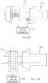
- FIG. 3 depicts an embodiment of the fluid pump mechanism 136, which is fluidly coupled to the removable fluid cartridge module 104 during operation of the fluid infusion device 100.
- the fluid pump mechanism 136 can be realized as a rotationally actuated micro pump that delivers a calibrated amount of medication fluid with each delivery cycle.
- the fluid pump mechanism 136 includes a stator and a rotor; the rotor is actuated in a controlled manner by a drive motor 138.
- the fluid pump mechanism 136 functions by translating rotational movement of the rotor into axial displacement of the rotor relative to the stator.
- the illustrated embodiment of the system architecture 400 generally includes, without limitation: a printed circuit board 401; the removable fluid cartridge module 104; the fluid pump mechanism 136; the drive motor 138; a fluid flow path 402; a fluid flow path 404; a cartridge sensor 406; one or more status sensors 408; one or more alerting devices 410; an insertion mechanism 412; and a subcutaneous conduit 413.
- FIG. 4 includes a number of items that were previously described, and those items will not be redundantly described in detail here.
- the alerting devices 410 can be electrically coupled to the printed circuit board 401 for purposes of controlled activation. In this regard, activation of the alerting devices 410 can be controlled by the processor device 420 as needed. In certain embodiments, user manipulation of the button 112 results in actuation of the switch 423, which in turn disables alerts or alarms generated by the alerting devices 410.
- the dashed arrow labeled "Cartridge Trigger Option” in FIG. 4 represents mechanical interaction (and/or electrical, magnetic, inductive, optical, capacitive, or other detection methodology) between the fluid cartridge module 104 and the insertion mechanism 412.
- installation of the fluid cartridge module 104 into the housing 106 can be detected to trigger the insertion mechanism 412.
- the insertion mechanism 412 fires to position the subcutaneous conduit 413 into a subcutaneous location.
- a devoted insertion button 416 is used to fire the insertion mechanism 412. Accordingly, the dashed arrow labeled "Button Trigger Option" in FIG.
- various elements of the systems described herein are essentially the code segments or computer-readable instructions that perform the various tasks.
- the program or code segments are stored in a tangible processor-readable medium, which may include any medium that can store or transfer information.
- Examples of a non-transitory and processor-readable medium include an electronic circuit, a semiconductor memory device, a ROM, a flash memory, an erasable ROM (EROM), a floppy diskette, a CD-ROM, an optical disk, a hard disk, or the like.
- the software that performs the described functionality may reside and execute at, for example, an ASIC.
- the processor device 420 can implement, cooperate with, or otherwise support the operation of a detection circuit (and applicable processing logic) that functions to detect downstream occlusions in a fluid flow path, upstream occlusions in a fluid flow path, end of reservoir conditions in a fluid infusion device, and/or other detectable operating conditions.
- the processor device 420 can execute suitably written computer instructions that cause the processor device 420 to perform the various detection tasks, operations, and method steps described below in the context of the different detection methodologies.
- Patient-specific programming can be achieved through a physician programmer via a wired or wireless communication session.
- an infrared window can be provided in the housing of the fluid infusion device to accommodate wireless adjustments or programming.
- Other methods to adjust the basal rate utilize a dial, a knob, or other adjustment component that the physician or patient can manipulate.
- the adjustment component can be connected to the printed circuit board 401 and, specifically, to the processor device 420 for purposes of changing the timing and/or other characteristics of the fluid pump mechanism 136.
- FIG. 4 depicts a basal rate adjustment component 422 that is intended to represent the various methodologies and components that serve to adjust the programmed basal rate of the fluid infusion device 100.
- One simple and low cost way to visualize and confirm the adjustment involves the use of a clear window on the housing of the fluid infusion device and a colored dial with markings corresponding to the adjustment setting.
- the system architecture 400 may include or cooperate with any combination of alerting devices 410, including, without limitation: a vibration motor; a piezoelectric audio transducer; one or more indicator lights (e.g., light emitting diodes or other lamp components); a speaker protected by a hydrophobic membrane; and the like.
- alerting devices 410 including, without limitation: a vibration motor; a piezoelectric audio transducer; one or more indicator lights (e.g., light emitting diodes or other lamp components); a speaker protected by a hydrophobic membrane; and the like.
- the axial movement of the rotor 502 away from the stator 504 as shown in FIG. 6 is produced by a cam structure (not shown) acting between the rotor 502 and the stator 504 forcing them progressively apart during a portion of the rotation.
- the cam structure may comprise a rising land disposed on a transverse face of one of the rotor 502 and the stator 504 interacting with a projection or cam follower on the other.
- the cam structure could be a radial pin engaging a helical grove extending part way round one of the interacting cylindrical surfaces.
- the biasing element 506 (which may be realized as a spring, such as the spring coupler 164 shown in FIG. 3 ) provides a biasing force that urges the rotor 502 toward the stator 504.
- the stator 704 has a different configuration than the stator 604 depicted in FIG. 9 , the operating concepts and functionality are identical for purposes of this description.
- the stator 704 includes a stator cam element 706 and a rotor opening 708 (as described above).
- the rotor 702 generally includes, without limitation: an endcap 712; a proximal axial extension 714; a distal axial extension 716; a first fluid supply channel 718 formed in the proximal axial extension 714; a second fluid supply channel 720 formed in the distal axial extension 716; and a rotor cam element 722.
- the fluid supply channels 718, 720 are realized as thin slits that extend from the outer surfaces of the axial extensions 714, 716. Sealing elements located inside the stator 704 cooperate with the fluid supply channels 718, 720 to act as valves that open and close as a function of the angular and axial position of the rotor 702 relative to the stator 704. This enables pumping of medication fluid supplied from the fluid cartridge module 104 (see FIG. 3 and FIG. 4 ) due to changes in volume available for fluid within the rotor chamber 610 caused by the axial displacement of the rotor 702.
- the endcap 712 can be suitably configured to mate with or otherwise cooperate with the drive motor 138, such that the angular position of the rotor 702 can be controlled as needed. Moreover, the endcap 712 can be suitably configured to mate with or otherwise cooperate with a biasing component that urges the rotor 702 toward the stator 704. For example, the endcap 712 can be coupled to or integrally fabricated with the spring coupler 164 shown in FIG. 3 .
- the axial displacement of the rotor 702 relative to the stator 704 is defined by the cooperating cam elements 706, 722.
- the cam elements contact each other during each pumping cycle to adjust the axial position of the rotor 702 as a function of the angular position of the rotor 702 relative to the stator 704.
- the rotor cam element 722 is positioned on the interior portion of the endcap 712, and it extends over a certain predefined arc.
- the rotor cam element 722 resembles a ramp having a variable height, i.e., progressively rising from a reference surface of the rotor 702. More specifically, the rotor cam element 722 increases in height over the predefined arc.
- FIG. 12 depicts a state where the stator cam element 706 resides on the rotor cam element 722. More specifically, the stator cam element 706 is positioned on the sloped portion of the rotor cam element 722. As the stator cam element 706 continues to "ride” along the rotor cam element 722, the rotor 702 becomes displaced relative to the stator 704. The maximum displacement occurs at the highest section (the plateau) of the rotor cam element 722. This maximum displacement in the discussion that follows is also referred to as the "extended” position.
- the illustrated embodiment of the rotor cam element 722 ends abruptly, as best shown in FIG. 13 , which depicts the vertical "shelf” defined at the end of the rotor cam element 722.
- FIG. 13 depicts the vertical "shelf” defined at the end of the rotor cam element 722.
- FIG. 15 is a graph that includes a plot of rotor axial position versus rotor angular position, for normal and typical operating conditions.
- the vertical axis indicates the axial position (displacement) of the rotor 702 relative to the stator 704, and the horizontal axis indicates the angular position of the rotor 702.
- One pumping cycle corresponds to 360 degrees of rotation, and FIG. 15 depicts a plot that spans two pumping cycles.
- FIG. 15 includes regions superimposed over the plot; the regions represent periods during which the valves are open.
- the fourth section 820 of the plot corresponds to a period of time immediately after the stator cam element 706 travels beyond the rotor cam element 722 (see FIG. 13 and FIG. 14 ).
- the stator cam element 706 "falls off' and disengages the plateau of the rotor cam element 722, and the biasing force axially displaces the rotor 702 toward the stator 704 such that the rotor cam element 722 moves toward the reference surface 736.
- the stator cam element 706 reaches and contacts the reference surface 736 and the rotor has returned to its axially retracted position.
- the fourth section 820 of the plot corresponds to a fluid expulsion period.
- the fifth section 822 of the plot (where the axial displacement is approximately zero) corresponds to another period during which the stator cam element 706 is in contact with the reference surface 736.
- the stator cam element 706 is in contact with the reference surface 736.
- the fifth section 822 is akin to the first section 814, and the next pumping cycle proceeds as the rotor 702 continues to rotate.
- the occlusion detection methodology presented here utilizes a sensor system integrated into the fluid pump mechanism.
- the basic design, configuration, and operation of the fluid pump mechanism are consistent with that previously described.
- the sensor system includes a metal trace or similarly conductive sensor contact element that is installed on or integrated into the rotor and in the area away from the rotor cam element (also referred to as the "off-ramp position").
- the sensor system also includes a sensing element on or integrated into the stator, wherein the sensing element cooperates with the sensor contact element during operation of the fluid pump mechanism.
- the sensing element is realized as two discrete traces or conductive leads that terminate in the area of the stator cam element.
- the sensor contact element can be shaped, sized, and positioned such that the stator cam element only makes contact with the sensor contact element during normal fluid delivery operations (and such that the stator cam element does not make contact with the sensor contact element when the downstream fluid path is occluded). This can be done by placing the sensor contact at the appropriate angular position on the rotor so that it contacts the conductive leads on the stator cam element following a successful expulsion of fluid. If the expulsion cannot occur due to a downstream occlusion, the sensor contact on the rotor does not reach the conductive leads on the stator. This angular position depends on the discharge valve timing.
- the contact needs to be positioned to sense whether the rotor reaches the retracted position as a result of discharge through the outlet valve. In the cycle of rotation the earliest position for the contact would be while the discharge valve is still open, and in normal circumstances, the discharge will already have occurred. The latest position corresponds to time immediately before the opening of the inlet valve for the next pumping cycle.
- the conductive traces on the stator can be interconnected to appropriately configured electronics, a detection circuit, a processor, or the like.
- Software running on the fluid infusion device can monitor the state of the sensor system (open/close, high/low, etc.) to determine an operating condition, such as the state of fluid delivery.
- the detection circuit observes one binary pattern produced by the sensor system (open, close, open, close, etc.) that correlates to the various intake and expulsion cycles.
- the detection circuit observes a different binary pattern (e.g., open, open), which in turn initiates an alarm or an alert message.
- the leads 878, 880 cooperate with the detection circuit 856 to detect whether or not the stator cam surface 876 is in contact with the sensor contact element 870.
- the detection circuit 856 can monitor the characteristics of a detection signal that is obtained from the leads 878, 880 in response to the changing angular position of the rotor 852.
- the detection signal could be a measured voltage, current, or the like, having two measurable states corresponding to a contact state and a non-contact state.
- the sensor contact element 870 is shaped, sized, and positioned such that, under normal and expected operating conditions, the stator cam element 874 is in contact with the sensor contact element 870 immediately following each fluid expulsion period.
- the stator cam element 874 remains in contact with the sensor contact element 870 for a defined angular range of the rotor 852, but the sensor contact element 870 ends before the angular position that corresponds to the next fluid intake period (i.e., the sensor contact element 870 ends before the lower edge 866 of the rotor cam element 864.
- the sensor contact element 870 is located in an area on the reference surface 862 that corresponds to a valve state in which the inlet valve is closed and the outlet valve is open (see FIG. 15 and FIG. 16 ).
- at least a portion of the sensor contact element 870 can be located in an area on the reference surface 862 that corresponds to a valve state in which both the inlet valve and the outlet valve are closed.
- the sensor contact element is instead located on the rim 882 of the endcap 858 (see FIG. 17 ).
- the angular span of the sensor contact element can be identical or functionally equivalent to that shown in FIG. 17 for the sensor contact element 870. Locating the sensor contact element on the rim 882 instead of inside the endcap 858 may be desirable for ease of manufacturing, reliability, and robust performance.
- the electrically conductive leads of the stator 854 will also be relocated for compatibility with the alternative positioning of the sensor contact element.
- the leads can be located on a rim or other surface 884 of the stator 854. This type of arrangement is also shown in FIGS.
- the EAP sensor 906 is fabricated from a material (such as a thin film) that generates energy, electricity, voltage, current, or a measurable quantity as a function of mechanical stress or strain imparted thereto.
- the response of the EAP sensor 906 can be detected and analyzed by the detection circuit 908 as needed.
- the EAP sensor 906 is suitably configured to detect or measure the expansion and contraction of the fluid conduit 904 in an ongoing manner.
- the fluid conduit 904 will remain pressurized in the presence of a downstream occlusion until the inlet valve opens again for the next intake stroke. Opening of the inlet valve allows the pressurized fluid to backflow into the upstream fluid path, which in turn allows the resilient fluid conduit 904 to shrink or collapse (relative to its pressurized state).
- the detection circuit 908 can analyze the output of the EAP sensor 906, determine that a downstream occlusion has occurred, and take appropriate action such as generating an alert.
- the output of the EAP sensor 906 can also be monitored to detect an "end of reservoir" condition.
- the stopper of the fluid reservoir no longer moves because it has reached the limit of its travel.
- the fluid pump mechanism 902 generates a negative pressure on the inlet side, which collapses the fluid conduit 904 to a greater extent than experienced during normal delivery (and the fluid conduit 904 does not recover back to its nominal shape).
- FIG. 20 shows the EAP sensor 906 monitoring an upstream fluid conduit that resides between the fluid cartridge module 900 and the fluid pump mechanism 902.
- This arrangement can be effective at detecting upstream occlusions (e.g., an end of reservoir condition).
- the system can employ a similar EAP sensor to monitor expansion and contraction of a downstream fluid conduit that is located downstream of the fluid pump mechanism 902. Monitoring a downstream fluid conduit can be effective for purposes of detecting downstream occlusions.
- a rotary fluid pump mechanism includes a rotor and a stator that cooperate to draw fluid from a fluid reservoir and deliver the fluid to an outlet conduit.
- Axial displacement of the rotor relative to the stator is a function of the angular position of the rotor. Simply put, the rotor moves back and forth relative to the stator during normal and expected fluid pumping cycles.
- the occlusion detection methodology presented in this section employs at least one non-contact sensing scheme to monitor the position of the rotor relative to the stator during operation of the fluid pump mechanism.
- the axial position of the rotor 940 exhibits substantially different characteristics in the presence of a downstream occlusion, due to the back pressure caused by the occlusion (see FIG. 16 ).
- the techniques presented here detect the relative position of the rotor and/or the stator during operation of the fluid infusion device, and the detected position information is used to determine whether or not the downstream fluid path is occluded.
- the occlusion detection system includes a force or pressure sensor 954 that is suitably configured and arranged to measure the biasing force associated with the rotor 940.
- a biasing element can be employed to urge the rotor 940 toward the stator 942.
- the sensor 954 measures the force 956, which can vary during a fluid delivery cycle.
- the force 956 can be characterized for normal and expected fluid delivery cycles and for downstream occlusion conditions, and the detection circuit 946 can be designed and programmed in an appropriate manner to respond to changes in the detected force profile that might be indicative of a downstream occlusion.
- FIG. 23 is a simplified perspective view of an exemplary embodiment of a rotor 960 having an electrical contact 962 attached thereto
- FIG. 24 is a simplified diagram of an exemplary embodiment of an occlusion detection system that cooperates with the rotor 960.
- the occlusion detection system also includes a variable resistance element 964 that cooperates with the electrical contact 962 to form a potentiometer.
- the electrical contact 962 and the variable resistance element 964 can be electrically coupled to a detection circuit 966, which supports the occlusion detection methodology described here.
- the variable resistance element 964 can be realized as a component of the detection circuit 966.
- the variable resistance element 964 can be integrated with or coupled to the stator of the fluid pump mechanism if so desired.
- FIG. 24 depicts the rotor 960 at the sensor interrogation time, i.e., when the electrical contact 962 is touching the variable resistance element 964.
- the angular position of the rotor 960 corresponds to a desired interrogation or sampling point of the fluid delivery cycle.
- the electrical contact 962 can be placed such that it contacts the variable resistance element 964 immediately following each expected fluid expulsion period (see FIG. 15 ).
- the specific timing can be determined based on the known angular position characteristics of the fluid pump mechanism.
- the rotor 960 is axially displaced as a function of its angular position.
- the arrow 970 in FIG. 24 represents the axial displacement of the rotor 960.
- Axial displacement of the rotor 960 causes the electrical contact 962 to shift back and forth, because the electrical contact 962 is fixed relative to the rotor 960.
- the electrical contact 962 should make contact with the variable resistance element 964 within a predictable and repeatable range of possible locations. Consequently, the resistance of the potentiometer changes, and a measured quantity (e.g., voltage) as detected by the detection circuit 966 will be within a certain range during normal delivery cycles.
- the electrical contact 962 will touch the variable resistance element 964 at a considerably different location when the downstream fluid flow path is occluded. Accordingly, the resistance of the potentiometer and the measured voltage will be outside of the normal range of values when the output flow path is occluded.
- the detection circuit 966 can be designed and programmed in an appropriate manner to respond to changes in the resistance of the potentiometer that might be indicative of a downstream occlusion.
- FIG. 24 depicts an embodiment where the electrical contact 962 resides on the rotor 960 and the variable resistance element 964 is external to the rotor 960. In other embodiments, the variable resistance element 964 resides on the rotor 960 and the electrical contact 962 is external to the rotor 960. Regardless of which configuration is used, the operating principle remains the same.
- the conductive contact 996 is designed such that the resistance of the conductive contact 996 varies as a function of its physical compression and/or deflection.
- the conductive contact 996 compresses or deflects more as the gap between the rotor 994 and the conductive rim 992 closes. Conversely, the conductive element expands or returns to its nominal shape as the gap increases.
- the resistance of the conductive contact 996 changes as a function of the axial displacement of the rotor 994 relative to the stator 990.
- the resistance between the conductive contact 996 and the conductive rim 992 can be measured by the detection circuit, which can be suitably designed and programmed to respond to changes in the measured resistance that might be indicative of a downstream occlusion.
- the arrangement depicted in FIG. 26 and FIG. 27 can also be configured for use as a simple on/off switching mechanism.
- the detection circuit can be designed to detect whether or not the conductive contact 996 is electrically coupled to the conductive rim 992.
- the conductive contact 996 and the conductive rim 992 are configured such that an electrical connection is made only when the stator cam element resides on the reference surface.
- the detection circuit can detect the presence of a downstream occlusion in a manner similar to that described above with reference to FIGS. 17-19 .
- FIG. 28 is a simplified diagram of an exemplary embodiment of an occlusion detection system that utilizes one or more force sensors in cooperation with the fluid pump mechanism.
- FIG. 28 depicts a stator 1002, a rotor 1004, and a biasing element 1006 of a fluid pump mechanism that functions in the manner generally described above with reference to FIGS. 5-16 .
- FIG. 28 also shows a force sensor 1008 positioned between the rotor 1004 and the stator 1002, and another force sensor 1010 positioned such that it can measure the biasing force of the biasing element 1006.
- FIG. 29 is a simplified diagram of an exemplary embodiment of an occlusion detection system that utilizes optical sensing technology.
- FIG. 29 depicts a stator 1022 and a rotor 1024 of a fluid pump mechanism that functions in the manner generally described above with reference to FIGS. 5-16 .
- the rotor 1024 includes at least one optically detectable feature that can be monitored during the operation of the fluid pump mechanism.
- FIG. 28 also shows an exemplary embodiment of an optically detectable feature, which is realized as an optically detectable pattern 1026 located on an exposed surface 1028 of the rotor 1024.
- the optically detectable pattern 1026 is a dot array, which can be printed, affixed to, or integrated into the exposed surface 1028. Other types of optically detectable patterns 1026 can be employed if so desired.
- end of reservoir detection can employ one or more of the following general methodologies, without limitation: (1) detecting that the stopper has reached an end position; (2) detecting that the fluid pump mechanism is pulling on a vacuum rather than drawing in fluid; (3) measurement of the stopper position over the length of the reservoir; and (4) observing axial displacement characteristics of the rotor relative to the stator.
- the fluid infusion device includes an outlet conduit 1106 having an inlet end 1108 and an outlet end 1110.
- the inlet end 1108 is designed to penetrate a septum 1112 of the fluid reservoir 1104, and the outlet end 1110 is in fluid communication with the fluid pump mechanism.
- the inlet end 1108 enters the barrel of the fluid reservoir 1104 to establish fluid communication with the medication fluid inside the barrel.
- the fluid infusion device also includes an electrically conductive needle 1114.
- the needle 1114 has a contact end 1116 that is designed to penetrate the septum 1112 for entry into the barrel of the fluid reservoir 1104.
- the outlet conduit 1106 and the needle 1114 are electrically connected to a suitably configured detection circuit (not shown).
- the needle 1114 can be connected to a negative voltage terminal and the outlet conduit 1106 can be connected to a positive voltage terminal (or vice versa).
- the outlet conduit 1106 is shorted with the needle 1114.
- This action is akin to the closing of a switch (as described in the immediately preceding section), which can be monitored and detected by the detection circuit.
- the stopper 1102 will not create a short across the needle 1114 and the outlet conduit 1106.
- the detection circuit determines that the fluid reservoir 1104 is at the "end of reservoir” state.
- the detection circuit can take appropriate action when it detects this state. For example, the detection circuit can initiate an "end of reservoir" alert, an alarm, or a message intended for the user or a caregiver.
- the fluid infusion device that hosts the fluid reservoir 1120 includes a suitably configured detection circuit (not shown) that includes, controls, or otherwise cooperates with an excitation signal generator 1122 and an associated sensor 1124.
- the excitation signal generator 1122 can be coupled to the fluid reservoir 1120 for purposes of applying an excitation signal to the fluid reservoir 1120.
- the excitation signal can be, for example, a vibration signal having a particular frequency or a particular frequency spectrum that is suitable for measuring the resonance or other response of the fluid reservoir 1120.
- the resonance of the fluid reservoir 1120 is influenced by the volume and/or mass of the fluid remaining in the fluid reservoir 1120. In practice, the resonance of the fluid reservoir 1120 can be empirically determined or otherwise characterized for purposes of programming the detection circuit.
- the detection circuit can obtain and analyze the response signal in an appropriate manner to determine whether or not the fluid reservoir 1120 is empty. If the response signal is indicative of an empty reservoir, the detection circuit can take appropriate action, e.g., initiate an "end of reservoir” alert, an alarm, or a message intended for the user or a caregiver.
- FIG. 37 is a simplified diagram of an exemplary embodiment of an end of reservoir detection system for a fluid reservoir 1130 of a fluid infusion device.
- the fluid reservoir 1130 provides medication fluid to a fluid pump mechanism of the type described above. The manner in which the fluid pump mechanism functions and cooperates with the fluid reservoir 1130 will not be redundantly described in detail here.
- the fluid infusion device that hosts the fluid reservoir 1120 includes a suitably configured detection circuit 1132 that includes, controls, or otherwise cooperates with a force sensor 1134.
- the force sensor 1134 can be configured as described above with reference to FIG. 28 .
- the force sensor 1134 can be used to measure the force imparted by a biasing element 1136 (such as a spring) that is coupled to the stopper 1138 of the fluid reservoir 1130.
- the tension characteristics of the biasing element 1136 are selected such that the biasing element 1136 cannot independently move the stopper 1138.
- the force applied by the biasing element 1136 is too low to overcome the static friction of the stopper 1138, and the biasing element 1136 is not utilized to actuate the stopper 1138 or to otherwise deliver fluid from the fluid reservoir 1130.
- the stopper 1138 is designed to move only in response to the negative fluid pressure caused by the normal operation of the fluid pump mechanism, as described in detail above. Consequently, the biasing element 1136 is strictly utilized to provide a force measurement that corresponds to the position of the stopper 1138 within the fluid reservoir 1130.
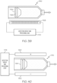
- FIG. 38 is a simplified diagram of an exemplary embodiment of an end of reservoir detection system for a fluid reservoir 1144 of a fluid infusion device.
- the fluid reservoir 1144 provides medication fluid to a fluid pump mechanism of the type described above. The manner in which the fluid pump mechanism functions and cooperates with the fluid reservoir 1144 will not be redundantly described in detail here.
- the fluid infusion device that hosts the fluid reservoir 1144 includes a suitably configured detection circuit 1146 that includes, controls, or otherwise cooperates with a pressure sensor 1148.
- the pressure sensor 1148 is designed to detect slight changes in the pressure of a sealed volume 1150 that is associated with the fluid reservoir 1144.
- FIG. 38 schematically depicts a vent 1152 leading from the sealed volume 1150 to the pressure sensor 1148. The vent 1152 allows the pressure sensor 1148 to monitor the pressure inside the sealed volume 1150 during operation of the fluid infusion device.
- the sealed volume 1150 can be defined by suitably configured structure of the fluid infusion device.
- the illustrated embodiment which is merely one possible implementation, includes a wall structure 1154 that at least partially surrounds the base of the fluid reservoir 1144.
- An airtight sealing element 1156 (such as an o-ring or a gasket) can be used to seal the wall structure 1154 against the outer surface of the fluid reservoir 1144.
- the sealed volume 1150 can be defined in any appropriate way, using additional structures or components if so desired.
- the shape and size of the sealed volume 1150 can vary from one embodiment to another.
- the pressure measurements obtained or otherwise processed by the detection circuit 1146 vary in accordance with the position of the stopper 1158 of the fluid reservoir 1144.
- the system is designed and configured such that the sealed volume 1150 does not adversely influence the normal operation of the fluid infusion device.
- the sealed volume 1150 should not impede the movement of the stopper 1158, which is caused by fluid intake strokes of the fluid pump mechanism.
- the detection circuit 1146 can obtain and analyze the output of the pressure sensor 1148 in an appropriate manner to determine whether or not the fluid reservoir 1144 is empty. If the measured pressure of the sealed volume 1150 is indicative of an empty reservoir, the detection circuit 1146 can take appropriate action, e.g., initiate an "end of reservoir" alert, an alarm, or a message intended for the user or a caregiver.
- the target 1166 and the coil element 1168 are suitably configured such that the inductance of the coil element 1168 varies (in a measurable manner) as a function of the position of the stopper 1164. Accordingly, the detection circuit 1170 observes a variable inductance as the stopper 1164 travels from the base of the fluid reservoir 1162 to the end position. The measured inductance can be correlated to the position of the stopper 1164, and the inductance corresponding to the end position of the stopper 1164 can be characterized for purposes of detecting the end of reservoir state. If the measured inductance of the coil element 1168 is indicative of an empty reservoir, the detection circuit 1170 can take appropriate action, e.g., initiate an "end of reservoir" alert, an alarm, or a message intended for the user or a caregiver.
- the system is provided with a device for detecting the presence of the stopper either at the forward position, thereby indicating that the barrel is empty or at intermediate positions giving an indication of the fill of the barrel.
- the outlet includes a needle passing through a septum in the outlet, the needle being positioned to be axially displaced by a contact with the stopper as it arrives at the forward position there being a switch operable by the needle outside of the barrel to indicate that the barrel is empty when the switch is actuated.
- the stopper and needle can be conductive closing an electrical circuit when the stopper touches the needle. In other arrangements, a second contact beside the needle is bridged by the presence of the stopper.
- Intermediate positions of the stopper can be detected by measuring the force in a spring extending from a position rearwardly of the stopper to a stopper, the pressure of a gas in the chamber behind the piston, the inductive properties of a ferromagnetic or conductive material within the stopper as detected by inductance from outside the reservoir or directed to detection of the liquid or stopper between the plates of a capacitor straddling the barrel.
- the detection of liquid in the barrel can be done by exciting the barrel rearwardly with respect to the stopper and detecting the excitation forward of the stopper. When the excitation and detection are either both adjacent, a non-liquid filled portion transmission between the excitation transducer and the reception transducer is improved due to the better impedance match.
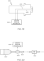
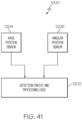
- FIG. 41 is a schematic block diagram of an exemplary embodiment of an end of reservoir detection system 1200 that can be implemented in a fluid infusion device having a rotary fluid pump mechanism.
- the fluid pump mechanism and the fluid reservoir are not shown in FIG. 41 .
- the manner in which the fluid pump mechanism functions and cooperates with the fluid reservoir will not be redundantly described in detail here.
- the angular position sensor 1206 is designed and configured to obtain angular position data of the rotor, where the angular position data indicates the rotational position of the rotor, relative to any convenient reference point.
- the angular position of the rotor can be expressed in degrees or in any appropriate units that correspond to angular measurement.
- the angular position sensor 1206 may be realized as a digital encoder or counter that monitors the operation of the drive motor, which in turn rotates the rotor.
- the respective sensor data or information is obtained by the detection circuit 1202 for processing and analysis. More specifically, the detection circuit 1202 can process the sensor data to determine whether or not an occlusion upstream of the fluid pump mechanism has occurred. The determination is based on certain detectable characteristics of the sensor data, wherein the detection circuit 1202 can determine whether the fluid pump mechanism is operating as expected to draw fluid in from the fluid reservoir and expel the fluid for delivery to the patient, or whether an upstream occlusion is preventing the fluid pump mechanism from drawing in fluid. As mentioned previously, an upstream occlusion may be detected when an inlet fluid flow path is blocked, or when the fluid reservoir is empty (and the stopper of the reservoir has reached its end position).
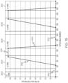
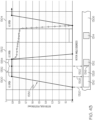
- the detection circuit 1202 calculates or otherwise obtains the axial velocity of the rotor during the fluid expulsion cycle.
- the section 820 of the plot represents the fluid expulsion period, during which the rotor normally "snaps back" into the stator under the force of the biasing element.
- the velocity of the rotor during this period can be characterized and predicted under normal and expected operating conditions. It should be understood that the slope of the section 820 is indicative of the axial velocity of the rotor (a gradual slope corresponds to lower velocity, and a steeper slope corresponds to higher velocity).
- an upstream occlusion is present (e.g., the fluid reservoir is empty and the stopper of the reservoir has reached its end position)
- the fluid pump mechanism will pull on a vacuum. Consequently, during the fluid intake period (corresponding to the section 816 of the plot in FIG. 15 ) the vacuum creates additional force in the same direction of the biasing force. This additional force increases the axial velocity of the rotor during the fluid expulsion cycle.
- the plot 1210 is characterized by a steeper slope during the expulsion period 1216.
- the steeper slope is indicative of higher axial velocity of the rotor during this time.
- the vacuum conditions created by an occlusion upstream of the fluid pump mechanism increase the axial velocity of the rotor during the fluid expulsion period (relative to the nominal axial velocity experienced during normal fluid delivery operations).
- the detection circuit 1202 is suitably configured and programmed to analyze the collected axial position and angular position sensor data in a way that is consistent with the comparison visualized in FIG. 42 .
- the detection circuit 1202 can calculate an average or maximum rotor axial velocity during the fluid expulsion period and compare the calculated velocity to a predetermined threshold axial velocity value. If the calculated axial velocity exceeds the threshold value, then the detection circuit 1202 can declare that an upstream occlusion has been detected.
- the detection circuit 1202 can consider the angular position data to determine the timing of the pumping cycle, such that the axial velocity of the rotor is analyzed during the fluid expulsion phase of the cycle (rather than at other times).
- the detection circuit 1202 can be programmed as needed to accurately characterize the axial velocity behavior of the rotor during the fluid expulsion period.
- the fluid expulsion period is characterized by a nominal axial velocity of the rotor
- the fluid expulsion period is characterized by a different axial velocity of the rotor, which is higher than the nominal axial velocity of the rotor.
- the upstream occlusion detection methodology presented in this section assumes that the fluid infusion device uses a fluid pump mechanism of the type described above, i.e., one having a stator and a cooperating rotor driven by a drive motor.
- the upstream occlusion detection methodology presented in this section analyzes the motor current of the drive motor to determine the operating condition or state of the fluid infusion device.
- one pumping cycle includes a fluid intake period (represented by the section 816 of the plot), a brief dwell period (represented by the section 818 of the plot), a fluid expulsion period (represented by the section 820 of the plot), and another dwell period (represented by the section 822 of the plot).
- the rotor cam element 722 travels along the stator cam element 706 during the fluid intake period and during the dwell period corresponding to the section 818 of the plot; the rotor cam element 722 disengages from the stator cam element 706 and moves toward the reference surface 736 during the fluid expulsion period; and the rotor cam element 722 travels along the reference surface 736 during the dwell period corresponding to the section 822 of the plot.
- the rotor cam element 722 travels along the stator cam element 706 during the fluid intake period and during the dwell period corresponding to the section 818 of the plot.
- the drive motor 138 is a DC motor, and that the current consumption of the drive motor 138 can be monitored and measured as it drives the rotor. It is well established that the current consumption of a DC motor is proportional to the output torque and the rotational speed (as torque increases, the current draw increases and the rotational speed decreases). Thus, when the rotor cam element 722 is traveling on the reference surface 736 and the applied biasing force is lower (the sections 814, 822 of the plot in FIG. 15 ), the motor current is somewhat stable, flat, and relatively low. In contrast, when the rotor cam element 722 is engaged with the stator cam element 706, the biasing spring force increases, which in turn increases the friction between the cam elements.
- the net effect is an increase in drive current consumption and torque output from the drive motor.
- the drive current peaks when the rotor cam element 722 reaches the plateau of the stator cam element 706, and then gradually decreases as the rotor cam element 722 continues traveling across the plateau. After the rotor cam element 722 disengages from the stator cam element 706 (i.e., the rotor cam element 722 falls off the plateau), the drive current returns to its relatively low and stable baseline level.
- the vacuum created by an empty reservoir or an upstream occlusion will increase the output torque during the fluid intake period (because the drive motor 138 must overcome the force created by the vacuum).
- the measured motor current will exhibit a steeper rise and a higher maximum value during the fluid intake period, relative to the normal motor current characteristics associated with non-occluded operation of the fluid pump mechanism.
- the detection circuit can be designed to take appropriate action if it observes this type of characteristic difference in the measured motor current. It should be appreciated that the methodology presented in this section can also be utilized to detect the presence of downstream occlusions if so desired.
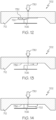
- FIG. 43 also schematically depicts the reference surface 1306 of a rotor 1308; the reference surface 1306 is rendered in a straight line (rather than a circle as depicted in FIG. 44 ) aligned with the rotor angle axis of the graph.
- FIG. 44 does not depict the endcap or surrounding structure of the rotor 1308.
- the rotor 1308 includes a rotor cam element 1310 having a variable height that rises from the reference surface 1306, as described in detail above with reference to FIGS. 11-14 .
- the illustrated embodiment of the rotor 1308 also includes a first (leading) sensor contact element 1312 located on or integrated with the reference surface 1306, and a second (trailing) sensor contact element 1314 located on or integrated with the reference surface 1306. As will become apparent from the following description, the second sensor contact element 1314 is utilized to support downstream occlusion detection.
- the behavior of the fluid pump mechanism under normal and occluded conditions can be characterized such that the sensor contact elements 1312, 1314 can be sized and positioned in an appropriate manner.
- the sensing element on the stator cam element makes no contact with the first sensor contact element 1312 because the rotor remains axially displaced from the stator throughout the angular position that corresponds to the location of the first sensor contact element 1312 on the reference surface 1306.
- the sensing element contacts the second sensor contact element 1314 once per pumping cycle because the rotor resides at its baseline axial position throughout the angular position that corresponds to the location of the second sensor contact element 1314 on the reference surface 1306. Accordingly, under normal operating conditions, the detection circuit will detect contact with only the second sensor contact element 1314 for each pumping cycle.
- FIG. 44 the sensor contact elements 1312, 1314 are located on the reference surface 1306 of the rotor 1308. Moreover, the embodiment of FIG. 44 cooperates with a sensing element incorporated into the stator cam element (of the type described above with reference to FIGS. 18 and 19 ).
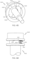
- FIG. 45 and FIG. 46 depict an alternative embodiment having a different arrangement of sensor contact elements.
- FIG. 45 is a perspective end view of an exemplary embodiment of a rotor 1400 of a fluid pump mechanism
- FIG. 46 is a side view that depicts the rotor 1400 cooperating with a compatible stator 1402 of the fluid pump mechanism.
- the first sensor contact element 1414 is located at an angular position that follows the upper edge 1420 of the rotor cam element 1404, and the second sensor contact element 1416 is located at an angular position that follows the first sensor contact element 1414.
- the plots shown in FIG. 43 for normal operating conditions, upstream occlusion conditions, and downstream occlusion conditions also apply to the embodiment depicted in FIG. 45 and FIG. 46 .
Landscapes
- Health & Medical Sciences (AREA)
- Vascular Medicine (AREA)
- Engineering & Computer Science (AREA)
- Anesthesiology (AREA)
- Biomedical Technology (AREA)
- Heart & Thoracic Surgery (AREA)
- Hematology (AREA)
- Life Sciences & Earth Sciences (AREA)
- Animal Behavior & Ethology (AREA)
- General Health & Medical Sciences (AREA)
- Public Health (AREA)
- Veterinary Medicine (AREA)
- Infusion, Injection, And Reservoir Apparatuses (AREA)
Description
- Embodiments of the subject matter described herein relate generally to fluid infusion devices of the type suitable for delivering a medication fluid to the body of a patient. More particularly, embodiments of the subject matter presented herein relate to techniques for detecting an occlusion in the fluid delivery path of a fluid infusion device having a rotary pump mechanism. An exemplary medication fluid is insulin used in the management of diabetes.
- Certain diseases or conditions may be treated, according to modem medical techniques, by delivering a medication fluid or other substance to the body of a patient, either in a continuous manner or at particular times or time intervals within an overall time period. For example, diabetes is commonly treated by delivering defined amounts of insulin to the patient at appropriate times. Some common modes of providing insulin therapy to a patient include delivery of insulin through manually operated syringes and insulin pens. Other modern systems employ programmable fluid infusion devices (e.g., insulin pumps) to deliver controlled amounts of insulin to a patient.
- A fluid infusion device suitable for use as an insulin pump may be realized as an external device or an implantable device, which is surgically implanted into the body of the patient. External fluid infusion devices include devices designed for use in a generally stationary location (for example, in a hospital or clinic bedside environment), and devices configured for ambulatory or portable use (to be carried or worn by a patient). External fluid infusion devices may establish a fluid flow path from a fluid reservoir or cartridge to the patient via, for example, a suitable hollow tubing, needle, or other type of fluid conduit.
- A fluid infusion device can be implemented with a rotary micropump mechanism that accurately delivers a precise volume of fluid with each revolution or cycle. The inlet of the micropump is connected to a fluid source such as a reservoir, and the outlet of the micropump is connected to a fluid delivery conduit that leads to the body of the patient. Under normal operating conditions, the micropump draws fluid from the fluid source (via a vacuum or suction action) and then delivers a predictable volume of fluid with each cycle.
- It is desirable to reliably and accurately detect at least two conditions, for purposes of alerting the user and/or to otherwise control the operation of the fluid infusion device in a responsive manner. One of these "fault" conditions is a downstream occlusion in the fluid delivery path (e.g., a blockage downstream from the outlet of the micropump). Another "fault" condition is an upstream occlusion (e.g., a blockage located before the inlet of the micropump). In this regard, an empty fluid reservoir can be considered to be an upstream occlusion because continued operation of the micropump in the presence of an empty reservoir does not result in the normally expected delivery of fluid.
AU2011232741 US2013/0017099 discloses a rotary pump having a rotor rotatably and axially slideably received within a chamber. The presence of occlusions is determined from analysis of measurements of the axial and rotation displacement of the rotor. - Accordingly, it is desirable to have a fluid infusion device and related operating methodologies that effectively detect upstream and/or downstream occlusions in the fluid delivery pathway associated with a rotary micropump. In addition, it is desirable to provide an improved rotary micropump having certain features and functionality that facilitate the detection of upstream and/or downstream occlusions in the fluid delivery pathway. Furthermore, other desirable features and characteristics will become apparent from the subsequent detailed description and the appended claims, taken in conjunction with the accompanying drawings and the foregoing technical field and background.
- Various upstream and downstream occlusion detection techniques and methodologies are disclosed herein. The occlusion detection techniques and methodologies can be implemented in a fluid infusion device that includes a rotary fluid pump mechanism (having a rotor and a stator). Actuation of the fluid pump mechanism draws fluid from a fluid reservoir during an intake stroke and expels the fluid during a delivery stroke.
- In accordance with certain embodiments, the fluid pump mechanism includes a stator having a fluid chamber defined therein, and also having a stator cam element with a stator cam surface. The fluid pump mechanism also includes a rotor having an endcap with a reference surface, an axial extension section protruding from the endcap, wherein at least a portion of the axial extension section fits inside the fluid chamber, and a rotor cam element having a variable height rising from the reference surface. The rotor cam element cooperates with the stator cam element to axially displace the rotor, relative to the stator, as a function of angular position of the rotor. A sensor contact element resides on the reference surface and is located in an area that is unoccupied by the rotor cam element. A sensing element terminates at or near the stator cam surface. The sensing element cooperates with a detection circuit to detect whether or not the stator cam surface is in contact with the sensor contact element. The detection circuit monitors characteristics of a detection signal obtained from the sensing element in response to angular position of the rotor to determine an operating condition of the fluid pump mechanism.
- Also presented here is an exemplary embodiment of a fluid infusion device for delivering a medication fluid to a body. The fluid infusion device includes a fluid pump mechanism that cooperates with a fluid cartridge module. The fluid pump mechanism has a rotor and a stator, wherein the rotor includes a reference surface and a rotor cam element having a variable height rising from the reference surface. The stator includes a stator cam element having a stator cam surface, wherein the rotor cam element cooperates with the stator cam element to axially displace the rotor, relative to the stator, as a function of angular position of the rotor. The fluid infusion device also includes a subcutaneous conduit in fluid communication with an outlet valve of the fluid pump mechanism, and a drive motor coupled to actuate the rotor of the fluid pump mechanism to pump medication fluid from the fluid cartridge module to the body, via the subcutaneous conduit. A sensor contact element is provided on the reference surface of the rotor. The sensor contact element is located in an area that is unoccupied by the rotor cam element. A sensing element terminates at or near the stator cam surface. The sensing element cooperates with a detection circuit to detect whether or not the stator cam surface is in contact with the sensor contact element. The detection circuit monitors characteristics of a detection signal obtained from the sensing element in response to angular position of the rotor to determine an operating condition of the fluid pump mechanism.
- An exemplary embodiment of a fluid pump mechanism is also presented here. The fluid pump mechanism includes: a stator; a rotor; an inlet valve that opens and closes as a function of angular and axial position of the rotor; an outlet valve that opens and closes as a function of angular and axial position of the rotor; a sensor contact element; and a sensing element. The stator cam element has a stator cam surface, and the rotor includes a reference surface and a rotor cam element having a variable height rising from the reference surface. The rotor cam element cooperates with the stator cam element to axially displace the rotor, relative to the stator, as a function of angular position of the rotor. The sensor contact element resides on the reference surface in an area corresponding to a valve state in which the inlet valve is closed and the outlet valve is open. The sensing element terminates at or near the stator cam surface, and it cooperates with a detection circuit to detect whether or not the stator cam surface is in contact with the sensor contact element. The detection circuit monitors characteristics of a detection signal obtained from the sensing element in response to angular position of the rotor to determine an operating condition of the fluid pump mechanism.
- Another exemplary embodiment of a fluid pump mechanism employs a force sensor to detect occlusions in the fluid path. The fluid pump mechanism includes a stator with a stator cam element having a stator cam surface. The fluid pump mechanism also includes a rotor with a reference surface and a rotor cam element having a variable height rising from the reference surface. The rotor cam element cooperates with the stator cam element to axially displace the rotor, relative to the stator, as a function of angular position of the rotor. A biasing element provides a biasing force to urge the rotor cam element toward the stator cam element and toward the reference surface. A force sensor is coupled to the rotor. The force sensor generates output levels in response to force imparted thereto, and the force sensor cooperates with a detection circuit that obtains and processes the output levels to detect occlusions in a fluid path downstream of the fluid pump mechanism.
- An exemplary embodiment of a fluid infusion device includes a fluid pump mechanism that cooperates with a fluid cartridge module. The fluid pump mechanism has a rotor and a stator. The rotor includes a reference surface and a rotor cam element having a variable height rising from the reference surface. The stator includes a stator cam element having a stator cam surface, wherein the rotor cam element cooperates with the stator cam element to axially displace the rotor, relative to the stator, as a function of angular position of the rotor. A biasing element provides a biasing force to urge the rotor cam element toward the stator cam element and toward the reference surface. The fluid infusion device also includes a subcutaneous conduit in fluid communication with an outlet valve of the fluid pump mechanism, and a drive motor coupled to actuate the rotor of the fluid pump mechanism to pump medication fluid from the fluid cartridge module to the body, via the subcutaneous conduit. A force sensor is coupled to the rotor to generate output levels in response to force imparted thereto. The force sensor cooperates with a detection circuit that obtains and processes the output levels to detect occlusions in a fluid path downstream of the fluid pump mechanism.
- An exemplary embodiment of a fluid infusion device includes a stator with a stator cam element having a stator cam surface, and a rotor with a reference surface and a rotor cam element having a variable height rising from the reference surface. The rotor cam element cooperates with the stator cam element to axially displace the rotor, relative to the stator, as a function of angular position of the rotor. A biasing element provides a biasing force to urge the rotor cam element toward the stator cam element and toward the reference surface. The fluid infusion device also includes an inlet valve that opens and closes as a function of angular and axial position of the rotor, and an outlet valve that opens and closes as a function of angular and axial position of the rotor. A force sensor is coupled to the rotor to generate output levels in response to force imparted thereto. A detection circuit cooperates with the force sensor to obtain and process the output levels of the force sensor to detect occlusions in a fluid path downstream of the fluid pump mechanism.
- In accordance with other exemplary embodiments, a fluid pump mechanism includes a stator with a stator cam element having a stator cam surface, and a rotor with an optically detectable feature, a reference surface, and a rotor cam element having a variable height rising from the reference surface. The rotor cam element cooperates with the stator cam element to axially displace the rotor, relative to the stator, as a function of angular position of the rotor. The optically detectable feature rotates and axially translates as a function of angular position of the rotor. An optical detection circuit interrogates the optically detectable feature during operation of the fluid pump mechanism to determine an operating condition of the fluid pump mechanism.
- An exemplary embodiment of a fluid infusion device includes a fluid pump mechanism that cooperates with a fluid cartridge module. The fluid pump mechanism includes a rotor and a stator, wherein the rotor has an optically detectable feature, a reference surface, and a rotor cam element having a variable height rising from the reference surface. The stator includes a stator cam element having a stator cam surface, such that the rotor cam element cooperates with the stator cam element to axially displace the rotor, relative to the stator, as a function of angular position of the rotor. The optically detectable feature rotates and axially translates as a function of angular position of the rotor, and a biasing element provides a biasing force to urge the rotor cam element toward the stator cam element and toward the reference surface. The fluid infusion device also includes: a subcutaneous conduit in fluid communication with an outlet valve of the fluid pump mechanism; a drive motor coupled to actuate the rotor of the fluid pump mechanism to pump medication fluid from the fluid cartridge module to the body, via the subcutaneous conduit; and an optical detection circuit to interrogate the optically detectable feature during operation of the fluid pump mechanism to determine an operating condition of the fluid pump mechanism.
- An exemplary embodiment of a fluid infusion device includes a stator with a stator cam element having a stator cam surface, and includes a rotor with an optically detectable feature, a reference surface, and a rotor cam element having a variable height rising from the reference surface. The rotor cam element cooperates with the stator cam element to axially displace the rotor, relative to the stator, as a function of angular position of the rotor. An inlet valve opens and closes as a function of angular and axial position of the rotor, and an outlet valve opens and closes as a function of angular and axial position of the rotor. An optical detection circuit cooperates with the optically detectable feature, wherein the optical detection circuit interrogates the optically detectable feature to determine an operating condition of the fluid infusion device.
- In accordance with certain exemplary embodiments, a fluid pump mechanism includes a stator with a stator cam element having a stator cam surface, and a rotor with a reference surface and a rotor cam element having a variable height rising from the reference surface. The rotor cam element cooperates with the stator cam element to axially displace the rotor, relative to the stator, as a function of angular position of the rotor. A biasing element provides a biasing force to urge the rotor cam element toward the stator cam element and toward the reference surface. A detection circuit processes axial and angular position data of the rotor, and determines that an upstream occlusion has occurred based on detectable characteristics of the axial and angular position data.
- An exemplary embodiment of a fluid infusion device includes: a fluid pump mechanism; a biasing element; a subcutaneous conduit; a drive motor; and a detection circuit. The fluid pump mechanism cooperates with a fluid cartridge module, and the fluid pump mechanism includes a rotor and a stator. The rotor includes a reference surface and a rotor cam element having a variable height rising from the reference surface, and the stator includes a stator cam element having a stator cam surface. The rotor cam element cooperates with the stator cam element to axially displace the rotor, relative to the stator, as a function of angular position of the rotor. The biasing element provides a biasing force to urge the rotor cam element toward the stator cam element and toward the reference surface. The subcutaneous conduit is in fluid communication with an outlet valve of the fluid pump mechanism. The drive motor is coupled to actuate the rotor of the fluid pump mechanism to pump medication fluid from the fluid cartridge module to the body, via the subcutaneous conduit. The detection circuit processes axial and angular position data of the rotor, and determines that an upstream occlusion has occurred based on detectable characteristics of the axial and angular position data.
- An exemplary embodiment of a fluid infusion device includes a stator with a stator cam element having a stator cam surface, and a rotor with a reference surface and a rotor cam element having a variable height rising from the reference surface. The rotor cam element cooperates with the stator cam element to axially displace the rotor, relative to the stator, as a function of angular position of the rotor. A biasing element provides a biasing force to urge the rotor cam element toward the stator cam element and toward the reference surface. An axial position sensor obtains axial position data of the rotor, and an angular position sensor obtains angular position data of the rotor. A detection circuit obtains and processes the axial position data and the angular position data, wherein the detection circuit determines that an upstream occlusion has occurred based on processing of the axial position data and the angular position data.
- In accordance with other exemplary embodiments, a fluid pump mechanism includes a stator with a stator cam element having a stator cam surface, and a rotor with a reference surface and a rotor cam element having a variable height rising from the reference surface. The rotor cam element cooperates with the stator cam element to axially displace the rotor, relative to the stator, as a function of angular position of the rotor. The fluid pump mechanism also includes an inlet valve that opens and closes as a function of angular and axial position of the rotor relative to the stator, and an outlet valve that opens and closes as a function of angular and axial position of the rotor relative to the stator. A biasing element provides a biasing force to urge the rotor toward the stator. A first sensor contact element resides on the rotor and is located at an angular position that follows an upper edge of the rotor cam element. A second sensor contact element resides on the rotor and is located at an angular position that follows the first sensor contact element. A sensing element resides on the stator, wherein the sensing element cooperates with a detection circuit to detect when the sensing element makes contact with the first sensor contact element and the second sensor contact element. The the detection circuit monitors characteristics of a detection signal obtained from the sensing element in response to angular position of the rotor to determine an operating condition of the fluid pump mechanism.
- An exemplary embodiment of a fluid infusion device includes a fluid pump mechanism that cooperates with a fluid cartridge module. The fluid pump mechanism includes a rotor and a stator; the rotor has a reference surface and a rotor cam element having a variable height rising from the reference surface. The stator includes a stator cam element having a stator cam surface, wherein the rotor cam element cooperates with the stator cam element to axially displace the rotor, relative to the stator, as a function of angular position of the rotor. An inlet valve opens and closes as a function of angular and axial position of the rotor relative to the stator, and an outlet valve opens and closes as a function of angular and axial position of the rotor relative to the stator. A biasing element provides a biasing force to urge the rotor toward the stator. A subcutaneous conduit is in fluid communication with the outlet valve, and drive motor is coupled to actuate the rotor of the fluid pump mechanism to pump medication fluid from the fluid cartridge module to the body, via the subcutaneous conduit. A first sensor contact element resides on the rotor and is located at an angular position that follows an upper edge of the rotor cam element. A second sensor contact element resides on the rotor and is located at an angular position that follows the first sensor contact element. A sensing element resides on the stator, and it cooperates with a detection circuit to detect when the sensing element makes contact with the first sensor contact element and the second sensor contact element. The detection circuit monitors characteristics of a detection signal obtained from the sensing element in response to angular position of the rotor to determine an operating condition of the fluid pump mechanism.
- An exemplary embodiment of a fluid pump mechanism includes a stator with a stator cam element having a stator cam surface. The fluid pump mechanism also includes a rotor having: an endcap with a rim; a reference surface located inside the endcap; and a rotor cam element located inside the endcap and having a variable height rising from the reference surface. The rotor cam element cooperates with the stator cam element to axially displace the rotor, relative to the stator, as a function of angular position of the rotor. A first sensor contact element resides on the rim of the endcap, and is located at an angular position that follows an upper edge of the rotor cam element. A second sensor contact element resides on the rim of the endcap, and is located at an angular position that follows the first sensor contact element. A biasing element provides a biasing force to urge the rotor toward the stator. The fluid pump mechanism also includes: an inlet valve that opens and closes as a function of angular and axial position of the rotor relative to the stator; an outlet valve that opens and closes as a function of angular and axial position of the rotor relative to the stator; and a sensing element that cooperates with a detection circuit to detect when the sensing element makes contact with the first sensor contact element and the second sensor contact element. The detection circuit monitors characteristics of a detection signal obtained from the sensing element to determine an operating condition of the fluid pump mechanism.
- The invention provides a pump for medication fluid. The rotary pump includes a stator, a rotationally drivable rotor disposed in the stator and axially movable between a retracted position and an extended position wherein in the retracted position, the rotor is fully seated within the stator, a cam arrangement disposed between the rotor and the stator to apply a force to urge the rotor towards the extended position during a first part of the rotation of the rotor then remove the force on further rotation in each of repeated pump cycles, and a biasing element positioned to urge the rotor back towards the retracted position. The pump also includes valving responsive to the angular position of the rotor including an inlet valve configured to open during a first arc of rotation for which the cam arrangement applies the force to the rotor and an outlet valve configured to open for a second arc of rotation after the force has been removed. The pump also includes an occlusion detector having an electrical contact on one of the rotor and stator and a conductive pad on the other of the rotor and stator. The contact and conductive pad are axially and rotationally positioned to only make contact if the rotor reaches the retracted position by the end of the second arc of rotation, the occlusion detector being configured to register an occlusion if such contact is not made.
- Another exemplary embodiment of a pump for medication fluid is also provided. The pump includes a stator, a rotationally drivable rotor disposed in the stator and axially movable between a retracted position and an extended position, a cam arrangement disposed between the rotor and the stator to apply a force to urge the rotor towards the extended position during a first part of the rotation of the rotor then remove the force on further rotation in each of repeated pump cycles, and a biasing element positioned to urge the rotor back towards the retracted position. The pump also includes valving responsive to the angular position of the rotor including an inlet valve configured to open during a first arc of rotation for which the cam arrangement applies the force to the rotor, and an outlet valve configured to open for a second arc of rotation after the force has been removed. The pump also includes an occlusion detector, wherein the valving is further configured to hold the outlet valve closed for a third arc of rotation between the first and second arcs, and the occlusion detector is configured to sense whether the rotor reaches the retracted position during the third arc of rotation and registers an occlusion if it does.
- Another embodiment of a pump for medication fluid is also provided. The pump includes a stator, a rotationally drivable rotor disposed in the stator and axially movable between a retracted position and an extended position, a cam arrangement disposed between the rotor and the stator to apply a force to urge the rotor towards the extended position during a first part of the rotation of the rotor then remove the force on further rotation in each of repeated pump cycles, and a biasing element positioned to urge the rotor back towards the retracted position. The pump includes valving responsive to the angular position of the rotor including an inlet valve configured to open during a first arc of rotation for which the cam arrangement applies the force to the rotor, and an outlet valve configured to open for a second arc of rotation after the force has been removed. The pump also includes an occlusion detector having a force sensor and nub disposed between the rotor and stator and positioned to touch to sense when the rotor is in the retracted position by the end of the second arc of rotation. The occlusion detector is configured to register an occlusion if the force sensor does not sense the touch within a pump cycle.
- Another exemplary embodiment of a pump for medication fluid is also provided. The pump has a stator, a rotationally drivable rotor disposed in the stator and axially movable between a retracted position and an extended position, a cam arrangement disposed between the rotor and the stator to apply a force to urge the rotor towards the extended position during a first part of the rotation of the rotor then remove the force on further rotation in each of repeated pump cycles, and a biasing element positioned to urge the rotor back towards the retracted position. The pump includes valving responsive to the angular position of the rotor including an inlet valve configured to open during a first arc of rotation for which the cam arrangement applies the force to the rotor, and an outlet valve configured to open for a second arc of rotation after the force has been removed. An occlusion detector includes an optical detector and indicia disposed between the rotor and stator and positioned to sense whether the rotor is in the retracted position by the end of the second arc of rotation, the occlusion detector being configured to register an occlusion if the optical sensor does not sense that the rotor is in the retracted position at that angular position.
- Another embodiment of a pump for medication fluid is provided. The pump includes a stator, a rotationally drivable rotor disposed in the stator and axially movable between a retracted position and an extended position, a cam arrangement disposed between the rotor and the stator to apply a force to urge the rotor towards the extended position during a first part of the rotation of the rotor then remove the force on further rotation in each of repeated pump cycles, and a biasing element positioned to urge the rotor back towards the retracted position. The pump also includes valving responsive to the angular position of the rotor including an inlet valve configured to open during a first arc of rotation for which the cam arrangement applies the force to the rotor, and an outlet valve configured to open for a second arc of rotation after the force has been removed. The pump has an occlusion detector configured to measure one or more kinematic quantities of the rotor in the axial direction at each of one or more respective rotational angles, and to comparing the measured kinematic quantities with reference kinematic quantities representing normal operation, and registering normal operation if the measured quantities are within a threshold range of the reference quantities.
- Also presented herein is an exemplary embodiment of an infusion system including a pump according to any of the preceding embodiments, a reservoir for the medication fluid and a catheter connected to the pump to conduct the medication to the user.
- Also presented herein is an exemplary embodiment of a method of detecting occlusion in a pump for medication fluid of the type having a rotationally drivable rotor disposed in a stator and axially movable between a retracted position and an extended position, having a cam arrangement disposed between the rotor and the stator to apply a force in each of repeated pump cycles to urge the rotor towards the extended position during a first part of the rotation of the rotor then remove the force on further rotation, there being a biasing element positioned to urge the rotor back towards the retracted position, and having valving responsive to the angular position of the rotor including an inlet valve configured to open during a first arc of rotation for which the cam arrangement applies the force to the rotor and an outlet valve configured to open for a second arc of rotation after the force has been removed. The method involves one or both of: (1) sensing whether the rotor reaches the retracted position by the end of the second arc of rotation and registering an occlusion if it does not; (2) holding the outlet valve closed for a third arc of rotation between the first and second arcs, and sensing whether the rotor reaches the retracted position during the third arc of rotation and registering an occlusion if it does.
- Also presented herein is another embodiment of a method of detecting occlusion in a pump for medication fluid of the type having a rotationally drivable rotor disposed in a stator and axially movable between a retracted position and an extended position, having a cam arrangement disposed between the rotor and the stator to apply a force in each of repeated pump cycles to urge the rotor towards the extended position during a first part of the angular rotation of the rotor then remove the force on further rotation, there being a biasing element positioned to urge the rotor back towards the retracted position, and having valving responsive to the angular position of the rotor including an inlet valve configured to open during a first arc of rotation for which the cam arrangement applies the force to the rotor and an outlet valve configured to open for a second arc of rotation after the force has been removed. The method involves measuring one or more kinematic quantities of the rotor in the axial direction at each of one or more respective rotational angles, and comparing the measured kinematic quantities with reference kinematic quantities representing normal operation at the respective rotational angles, and registering normal operation if the measured quantities are within a threshold range of the reference quantities.
- This summary is provided to introduce a selection of concepts in a simplified form that are further described below in the detailed description. This summary is not intended to identify key features or essential features of the claimed subject matter, nor is it intended to be used as an aid in determining the scope of the claimed subject matter.
- A more complete understanding of the subject matter may be derived by referring to the detailed description and claims when considered in conjunction with the following figures, wherein like reference numbers refer to similar elements throughout the figures.
-
FIG. 1 is a top perspective view of an embodiment of a fluid infusion device implemented as a patch pump device; -
FIG. 2 is a perspective view that depicts the insertion of the removable fluid cartridge module into the fluid infusion device; -
FIG. 3 is a perspective view that shows certain internal components of the fluid infusion device; -
FIG. 4 is a block diagram representation of the system architecture of a fluid infusion device according to certain embodiments; -
FIGS. 5-8 are diagrams that depict a fluid pump mechanism in various stages during one pump cycle; -
FIG. 9 is an exploded perspective view of a stator and a rotor of an exemplary embodiment of a fluid pump mechanism; -
FIG. 10 is a perspective view of an exemplary embodiment of a stator of a fluid pump mechanism; -
FIG. 11 is a perspective view of an exemplary embodiment of a rotor of a fluid pump mechanism; -
FIGS. 12-14 are diagrams that depict the cooperation between a stator cam element and a rotor cam element of a fluid pump mechanism; -
FIG. 15 is a graph that includes a plot of rotor axial position versus rotor angular position; -
FIG. 16 is a graph that includes a plot of rotor axial position versus rotor angular position for a downstream occlusion condition; -
FIG. 17 is an end view of an exemplary embodiment of a rotor of a fluid pump mechanism; -
FIG. 18 is an end view of an exemplary embodiment of a stator of a fluid pump mechanism; -
FIG. 19 is a diagram that depicts the stator shown inFIG. 18 cooperating with a detection circuit; -
FIG. 20 is a schematic block diagram that illustrates an exemplary embodiment of an occlusion detection system suitable for use with a fluid infusion device; -
FIG. 21 is a simplified diagram of an exemplary embodiment of an optical or acoustic based occlusion detection system suitable for use with a fluid infusion device; -
FIG. 22 is a simplified diagram of an exemplary embodiment of an occlusion detection system that utilizes position sensing techniques; -
FIG. 23 is a simplified perspective view of an exemplary embodiment of a rotor of a fluid pump mechanism; -
FIG. 24 is a simplified diagram of an exemplary embodiment of an occlusion detection system that utilizes a potentiometer as a sensing element; -
FIG. 25 is a simplified diagram of an exemplary embodiment of an occlusion detection system that utilizes an electrical contact as a digital switch; -
FIG. 26 is a simplified end view of a stator having an electrically conductive rim; -
FIG. 27 is a simplified diagram of an exemplary embodiment of an occlusion detection system that cooperates with the stator shown inFIG. 26 ; -
FIG. 28 is a simplified diagram of an exemplary embodiment of an occlusion detection system that utilizes a force sensor; -
FIG. 29 is a simplified diagram of an exemplary embodiment of an occlusion detection system that utilizes optical sensing technology; -
FIG. 30 is a simplified perspective view of an exemplary embodiment of a rotor having physical features that cooperate with an optical detection circuit; -
FIG. 31 is a side view of a section of the rotor shown inFIG. 30 ; -
FIG. 32 is a simplified diagram of an exemplary embodiment of an end of reservoir detection system interrogating a fluid reservoir; -
FIG. 33 is a simplified diagram of the end of reservoir detection system detecting an empty reservoir condition; -
FIG. 34 is a simplified diagram of an exemplary embodiment of an end of reservoir detection system that implements a mechanical switch concept; -
FIG. 35 is a simplified diagram of an exemplary embodiment of an end of reservoir detection system that utilizes a conductive fluid reservoir stopper (or a conductive element of a stopper); -
FIG. 36 is a simplified diagram of an exemplary embodiment of an end of reservoir detection system that applies an excitation signal to a fluid reservoir; -
FIG. 37 is a simplified diagram of an exemplary embodiment of an end of reservoir detection system that uses a force sensor to determine the position of a stopper of a fluid reservoir; -
FIG. 38 is a simplified diagram of an exemplary embodiment of an end of reservoir detection system that uses a pressure sensor to determine the position of a stopper of a fluid reservoir; -
FIG. 39 is a simplified diagram of an exemplary embodiment of an end of reservoir detection system that measures an inductance to determine the position of a stopper of a fluid reservoir; -
FIG. 40 is a simplified diagram of an exemplary embodiment of an end of reservoir detection system that measures a capacitance to determine the position of a stopper of a fluid reservoir; -
FIG. 41 is a schematic block diagram of an exemplary embodiment of an end of reservoir detection system that measures axial velocity of a rotor of a fluid pump mechanism; -
FIG. 42 is a graph that includes a plot of rotor axial position versus rotor angular position for an upstream occlusion condition; -
FIG. 43 is a graph that includes plots of rotor axial position versus rotor angular position for various operating conditions of a fluid pump mechanism; -
FIG. 44 is a perspective view of an exemplary embodiment of a rotor of a fluid pump mechanism; -
FIG. 45 is a perspective end view of another exemplary embodiment of a rotor of a fluid pump mechanism; and -
FIG. 46 is a side view that depicts the rotor ofFIG. 45 cooperating with a stator. - The following detailed description is merely illustrative in nature and is not intended to limit the embodiments of the subject matter or the application and uses of such embodiments. As used herein, the word "exemplary" means "serving as an example, instance, or illustration." Any implementation described herein as exemplary is not necessarily to be construed as preferred or advantageous over other implementations. Furthermore, there is no intention to be bound by any expressed or implied theory presented in the preceding technical field, background, brief summary or the following detailed description.
- Certain terminology may be used in the following description for the purpose of reference only, and thus are not intended to be limiting. For example, terms such as "upper", "lower", "above", and "below" could be used to refer to directions in the drawings to which reference is made. Terms such as "front", "back", "rear", "side", "outboard", and "inboard" could be used to describe the orientation and/or location of portions of the component within a consistent but arbitrary frame of reference which is made clear by reference to the text and the associated drawings describing the component under discussion. Such terminology may include the words specifically mentioned above, derivatives thereof, and words of similar import. Similarly, the terms "first", "second", and other such numerical terms referring to structures do not imply a sequence or order unless clearly indicated by the context.
- The following description relates to a fluid infusion device of the type used to treat a medical condition of a patient. The infusion device is used for infusing fluid (such as a medication) into the body of a user. The non-limiting examples described below relate to a medical device used to treat diabetes (more specifically, an insulin infusion device), although embodiments of the disclosed subject matter are not so limited. Accordingly, the infused medication fluid is insulin in certain embodiments. In alternative embodiments, however, many other fluids may be administered through infusion such as, but not limited to, disease treatments, drugs to treat pulmonary hypertension, iron chelation drugs, pain medications, anti-cancer treatments, medications, vitamins, hormones, or the like. For the sake of brevity, conventional features and characteristics related to infusion system operation, insulin pump operation, fluid reservoirs, and fluid conduits such as soft cannulas may not be described in detail here.
-
FIG. 1 is a top perspective view of an embodiment of afluid infusion device 100 implemented as a patch pump device,FIG. 2 is a perspective view that depicts the insertion of a removablefluid cartridge module 104 into thefluid infusion device 100, andFIG. 3 is a perspective view that shows certain internal components of thefluid infusion device 100. The removablefluid cartridge module 104 is designed and configured for compatibility with thefluid infusion device 100, andFIG. 1 shows thefluid cartridge module 104 installed and secured within thefluid infusion device 100. The figures depict one possible configuration and form factor of thefluid infusion device 100. It should be appreciated that other designs and configurations can be utilized if so desired, and that the particular design aspects shown in the figures are not intended to limit or otherwise restrict the scope or application of the embodiments described herein. - The
fluid infusion device 100 includes ahousing 106 that serves as a shell for a variety of internal components. Thehousing 106 is suitably configured to receive, secure, and release the removablefluid cartridge module 104. In this regard, thefluid cartridge module 104 can be received in a suitably shaped, sized, and configured cavity that is designed in accordance with certain physical characteristics of thefluid cartridge module 104. For example, thehousing 106 can include structural features that mate with or otherwise engage structural features of thefluid cartridge module 104. The illustrated embodiment of the removablefluid cartridge module 104 includes aretention mechanism 110 that secures thefluid cartridge module 104 in the properly installed and seated position within thefluid infusion device 100. Theretention mechanism 110 locks thefluid cartridge module 104 in place within the cavity 108 to maintain the necessary physical and fluid connections between thefluid cartridge module 104 and thefluid infusion device 100. Theretention mechanism 110 can be physically manipulated to release thefluid cartridge module 104 from thehousing 106 as needed (e.g., to replace one cartridge module with a different cartridge module, to remove the cartridge module when replacing an old fluid infusion device with a new fluid infusion device, or the like). In practice, theretention mechanism 110 can be realized as a latching feature, a locking feature, a tab, or the like. - The
fluid infusion device 100 includes at least one user interface feature, which can be actuated by the patient as needed. The illustrated embodiment of thefluid infusion device 100 includes abutton 112 that is physically actuated. Thebutton 112 can be a multipurpose user interface if so desired to make it easier for the user to operate thefluid infusion device 100. In this regard, thebutton 112 can be used in connection with one or more of the following functions, without limitation: waking up the processor and/or electronics of thefluid infusion device 100; triggering an insertion mechanism for actuating a transcutaneous conduit assembly (e.g., inserting a cannula into the subcutaneous space, or similar region of the patient); configuring one or more settings of thefluid infusion device 100; initiating delivery of medication fluid; initiating a fluid priming operation; disabling alerts or alarms generated by thefluid infusion device 100; and the like. In lieu of thebutton 112, thefluid infusion device 100 can employ a slider mechanism, a pin, a lever, or the like. - The
fluid infusion device 100 includes an adhesive element or adhesive material (hidden from view inFIG. 1 andFIG. 2 ) that can be used to affix thehousing 106 to the body of the patient. The adhesive element can be located on the bottom surface of thehousing 106 such that thehousing 106 can be temporarily adhered to the skin of the patient. The adhesive element may be, for example, a piece of double sided adhesive tape that is cut into the desired shape and size. Thefluid infusion device 100 is manufactured with an adhesive liner overlying the adhesive element; the adhesive liner is peeled away to expose the sticky surface of theadhesive element 114. The adhesive element is chosen to be strong enough to maintain thefluid infusion device 100 in place for the desired period of time (which is typically between one to seven days) and strong enough to withstand typical use cases (e.g., showering, rainy days, physical exercise, etc.), while also being easy to remove without discomfort. - Setup and operation of the
fluid infusion device 100 is simple and straightforward for the patient. In this regard, the particular procedure for setup and initiation may vary from one embodiment to another, depending on the specific configuration, design, form factor, and/or optional settings of thefluid infusion device 100. In accordance with one high level method of operation, thefluid infusion device 100 is deployed in the following manner: (1) insert thefluid cartridge module 104 into thehousing 106; (2) remove the adhesive liner; (3) affix thehousing 106 to the body; and (4) insert the fluid delivery cannula into the body by pressing a button, pulling a tab, removing a safety pin, or otherwise activating an insertion mechanism to release a preloaded spring or equivalent actuation component. Thereafter, the fluid infusion device can be prepared for the delivery of the medication fluid as needed. - In accordance with an alternative method of operation, the
fluid cartridge module 104 is installed after thehousing 106 is affixed to the body. In accordance with this option, the action of installing thefluid cartridge module 104 into thehousing 106 engages or moves a mechanical, electrical, magnetic, or other type of interface, which in turn releases a preloaded spring or equivalent actuation component to insert the fluid delivery cannula into the body. Once the spring is released upon the first cartridge insertion, thefluid infusion device 100 is put into a different state such that subsequent installations of a fluid cartridge module will not trigger the insertion mechanism again. - In certain embodiments, the
fluid infusion device 100 is realized as a single-piece disposable component that is designed for continuous use over a designated period of time, such as three days. Although not always required, thefluid infusion device 100 can be designed to accommodate prefilledfluid cartridge modules 104, which may be provided by third party manufacturers in "off the shelf' volumes (e.g., 1.0 mL, 1.5 mL, 2.0 mL, or 3.0 mL of medication fluid). It should be appreciated that thefluid infusion device 100 can also be suitably configured and designed to accommodate user-filledfluid cartridge modules 104. Referring toFIG. 2 , each removablefluid cartridge module 104 can be realized as a single-use disposable reservoir that is not designed or intended to be refilled. The illustrated embodiment of the fluidreservoir cartridge module 104 includes a glass orplastic reservoir 116 that is held in acarrier 118 or housing to facilitate insertion and removal of thereservoir 116. - As mentioned above, the
housing 106 of thefluid infusion device 100 receives the removablefluid cartridge module 104 containing the desired medication fluid. Thehousing 106 also serves to contain the variety of components and elements that cooperate to support the functionality of thefluid infusion device 100. These internal components and elements can include, without limitation: a printed circuit board; a vibration motor or other haptic feedback element; a battery or other energy source; a fluid pump mechanism; a drive motor coupled to actuate the fluid pump mechanism (or other devices, components, or means to actuate the fluid pump mechanism, such as a solenoid, a nickel-titanium memory wire, or the like); an insertion mechanism for actuating a transcutaneous conduit assembly; sensors that interact with the drive motor, the fluid pump mechanism, and/or thebutton 112; an outlet fluid conduit; and an inlet conduit assembly. Of course, an embodiment of thefluid infusion device 100 may include additional features, components, devices, and elements that are not depicted in the figures or described in detail here. - The printed circuit board includes various electronic components, devices, and connections that cooperate to support the functions of the
fluid infusion device 100. These components are enclosed within thehousing 106 for protection, water resistance, and the like. The printed circuit board 130 may include or cooperate with any of the following, without limitation: switches; adjustment or trim elements such as a potentiometer; a processor device; memory; or the like. The vibration motor can be used to generate confirmation or alert signals as needed. Alternatively or additionally, thefluid infusion device 100 can include an audio transducer, an indicator light, a display element, or other components to provide feedback to the user. The battery can be a single use element that can be discarded with the fluid infusion device. The battery provides the required voltage and current to operate thefluid infusion device 100. -
FIG. 3 depicts an embodiment of thefluid pump mechanism 136, which is fluidly coupled to the removablefluid cartridge module 104 during operation of thefluid infusion device 100. Thefluid pump mechanism 136 can be realized as a rotationally actuated micro pump that delivers a calibrated amount of medication fluid with each delivery cycle. In this regard, thefluid pump mechanism 136 includes a stator and a rotor; the rotor is actuated in a controlled manner by adrive motor 138. As described in more detail below, thefluid pump mechanism 136 functions by translating rotational movement of the rotor into axial displacement of the rotor relative to the stator. In turn, the translational movement results in the opening and closing of a series of valves that are internal to thefluid pump mechanism 136 for purposes of drawing in the medication fluid from thefluid cartridge module 104. A biasing force (e.g., a spring force) forces the rotor toward the stator, which expels the fluid through the outlet of thefluid pump mechanism 136. In certain embodiments, thefluid pump mechanism 136 leverages the pump technology offered by Sensile Medical, although other types of pump technologies can also be utilized. - In accordance with certain embodiments, the biasing force that urges the rotor into the stator is provided by a molded plastic part that serves as both the spring element and a coupling component (to mechanically couple the
drive motor 138 to the rotor). Thisspring coupler 164 is shown inFIG. 3 . Thespring coupler 164 eliminates the need for a separate coupling element, which reduces parts count, reduces product cost, and simplifies manufacturing and assembly of thefluid infusion device 100. Thespring coupler 164 can be a physically distinct component that is mechanically attached between thedrive motor 138 and the rotor of thefluid pump mechanism 136. In alternative embodiments, thespring coupler 164 can be integrally fabricated with the rotor. - The
drive motor 138 can be a direct current (DC) motor, a brushless DC motor, a stepper motor, or the like. It should be appreciated that other drive methodologies could be used instead of thedrive motor 138, such as a nickel titanium memory wire and a ratcheting mechanism to create rotational motion to drive thefluid pump mechanism 136. - Thus, a full rotation of the rotor results in the delivery of a known amount of medication fluid. After the fluid flow path of the
fluid infusion device 100 has been primed, each rotation of the rotor draws a measured volume of medication fluid from thefluid cartridge module 104 and expels the same amount of medication fluid from the cannula situated in the patient. - With continued reference to
FIG. 3 , aninlet conduit assembly 144 includes structure that is compatible with the removablefluid cartridge module 104. For example, theinlet conduit assembly 144 includes afluid conduit 150 that terminates at a hollow reservoir needle (hidden from view because it extends into the fluid cartridge module 104). The hollow reservoir needle enters the reservoir of the fluid cartridge module 104 (via a septum) when thefluid cartridge module 104 is installed in thefluid infusion device 100. Thefluid infusion device 100 also includes a sealingelement 154, which may be coupled to the inlet conduit assembly 144 (alternatively, the sealingelement 154 can be an integral part of the inlet conduit assembly 144). The sealingelement 154 can be a compressible and resilient component that creates a fluid seal for theinlet conduit assembly 144 when thefluid cartridge module 104 is removed from thehousing 106 of thefluid infusion device 100. More specifically, the sealingelement 154 is compressed when thefluid cartridge module 104 is installed, thus exposing the hollow reservoir needle. The sealingelement 154 extends to cover the end of the hollow reservoir needle when thefluid cartridge module 104 is removed, which inhibits the ingress of contaminants, fluid, and air into theinlet conduit assembly 144, and which inhibits leakage of medication fluid from the fluid flow path of thefluid infusion device 100. - Moreover, the
inlet conduit assembly 144 is in fluid communication with afluid inlet 156 of thefluid pump mechanism 136. Thefluid inlet 156 accommodates and receives an end of thefluid conduit 150, as shown inFIG. 3 . This arrangement allows thefluid pump mechanism 136 to draw the medication fluid in from thefluid cartridge module 104, via theinlet conduit assembly 144. Thefluid pump mechanism 136 expels the medication fluid from afluid outlet 158, which is in fluid communication with theoutlet fluid conduit 142.FIG. 3 depicts only a portion of theoutlet fluid conduit 142. In certain embodiments, theoutlet fluid conduit 142 may be realized as part of a transcutaneous conduit assembly of thefluid infusion device 100, wherein the transcutaneous conduit assembly also includes a subcutaneous conduit (e.g., a soft cannula) that is inserted and positioned within the body of the patient. - The transcutaneous conduit assembly is in fluid communication with the
fluid outlet 158 of thefluid pump mechanism 136. More specifically, in accordance with the illustrated embodiment, theoutlet fluid conduit 142 is implemented as a flexible hollow needle having its proximal end fluidly coupled to thefluid outlet 158. The distal end of the flexible hollow needle is sharp to accommodate the insertion of the subcutaneous conduit into the body of the patient during an insertion operation. The distal end of the flexible hollow needle is not shown inFIG. 3 . The proximal end of the subcutaneous conduit is fluidly coupled to the flexible hollow needle such that at least a portion of the needle is initially inside the subcutaneous conduit (i.e., the subcutaneous conduit is carried by the flexible hollow needle before and during an insertion operation). Accordingly, the subcutaneous conduit is in fluid communication with thefluid pump mechanism 136 such that the medication fluid can be delivered to the body of the patient via theoutlet fluid conduit 142 and the subcutaneous conduit. - The
fluid infusion device 100 includes a flow path that accommodates the delivery of the medication fluid from thefluid cartridge module 104 to a subcutaneous site in the body of the patient. A first fluid flow path is at least partially defined by theinlet conduit assembly 144, which resides between thefluid cartridge module 104 and thefluid pump mechanism 136. The first fluid flow path may be considered to be the inlet flow path of thefluid pump mechanism 136. A second flow path (which may be considered to be the outlet flow path of the fluid pump mechanism 136) is defined by theoutlet fluid conduit 142 and the subcutaneous conduit. In this regard, the second flow path terminates at the distal end of the subcutaneous conduit. The overall flow path of thefluid infusion device 100, therefore, includes the first fluid flow path, thefluid pump mechanism 136, and the second fluid flow path. It should be appreciated that the fluid flow path through thefluid infusion device 100 can be established using any number of rigid needles (bent or straight), soft tubing, flexible steel tubing, or the like. The particular embodiment described herein is merely one possible arrangement. -
FIG. 4 is a block diagram that depicts an exemplary embodiment of asystem architecture 400 suitable for use with thefluid infusion device 100.FIG. 4 depicts thehousing 106 of thefluid infusion device 100, along with various components, elements, and devices that are housed by, enclosed within, or attached to thehousing 106. InFIG. 4 , solid arrows represent electrical signal paths, dashed arrows represent mechanical interaction or cooperation between elements, and doubled arrows represent fluid flow paths. It should be appreciated that an embodiment of thesystem architecture 400 can include additional elements, components, and features that may provide conventional functionality that need not be described herein. Moreover, an embodiment of thesystem architecture 400 can include alternative elements, components, and features if so desired, as long as the intended and described functionality remains in place. - The illustrated embodiment of the
system architecture 400 generally includes, without limitation: a printed circuit board 401; the removablefluid cartridge module 104; thefluid pump mechanism 136; thedrive motor 138; afluid flow path 402; afluid flow path 404; acartridge sensor 406; one ormore status sensors 408; one ormore alerting devices 410; aninsertion mechanism 412; and asubcutaneous conduit 413.FIG. 4 includes a number of items that were previously described, and those items will not be redundantly described in detail here. - The printed circuit board 401 may include or carry at least some of the electronics of the
fluid infusion device 100, e.g., any number of discrete or integrated devices, components, electrical conductors or connectors, and the like. For example, the following items may be found on the printed circuit board 401, without limitation: abattery 414; aprocessor device 420; a basalrate adjustment component 422; and aswitch 423. The printed circuit board 401 (or the items carried by the printed circuit board 401) can be electrically coupled to other elements of thesystem architecture 400 as needed to support the operation of thefluid infusion device 100. For example, the printed circuit board 401 can be electrically coupled to at least the following, without limitation: thefluid cartridge module 104; thefluid pump mechanism 136; thedrive motor 138; thecartridge sensor 406; thestatus sensors 408; and the alertingdevices 410. It should be appreciated that electrical connections to the printed circuit board 401 can be direct or indirect if so desired. Moreover, one or more components on the printed circuit board 401 may support wireless data communication in some embodiments. - The
flow path 402 fluidly couples thefluid cartridge module 104 to the inlet of thefluid pump mechanism 136, and theflow path 404 fluidly couples the outlet of thefluid pump mechanism 136 to thesubcutaneous conduit 413. Thesubcutaneous conduit 413 is fluidly coupled to the body of the patient. Thedrive motor 138 is electrically and mechanically coupled to thefluid pump mechanism 136 to control the operation of thefluid pump mechanism 136. Thus, thedrive motor 138 can be turned on and off as needed by theprocessor device 420 to control the position of the rotor of thefluid pump mechanism 136. - The
status sensors 408 can be electrically coupled to thefluid pump mechanism 136 and to the printed circuit board 401 to monitor certain operating conditions, parameters, or characteristics of thefluid pump mechanism 136 and/or other components of thefluid infusion device 100. For example, the information provided by thestatus sensors 408 can be processed or otherwise utilized to determine the revolution count of thefluid pump mechanism 136, to determine the resting position of thefluid pump mechanism 136, to detect a downstream occlusion in the fluid delivery path, to detect when the reservoir of thefluid cartridge module 104 is empty, or the like. - The alerting
devices 410 can be electrically coupled to the printed circuit board 401 for purposes of controlled activation. In this regard, activation of the alertingdevices 410 can be controlled by theprocessor device 420 as needed. In certain embodiments, user manipulation of thebutton 112 results in actuation of theswitch 423, which in turn disables alerts or alarms generated by the alertingdevices 410. - The dashed arrow labeled "Cartridge Trigger Option" in
FIG. 4 represents mechanical interaction (and/or electrical, magnetic, inductive, optical, capacitive, or other detection methodology) between thefluid cartridge module 104 and theinsertion mechanism 412. In this regard, installation of thefluid cartridge module 104 into thehousing 106 can be detected to trigger theinsertion mechanism 412. If thesubcutaneous conduit 413 is not yet inserted in the body of the patient (i.e., the spring mechanism has not been actuated), then theinsertion mechanism 412 fires to position thesubcutaneous conduit 413 into a subcutaneous location. In alternative embodiments, adevoted insertion button 416 is used to fire theinsertion mechanism 412. Accordingly, the dashed arrow labeled "Button Trigger Option" inFIG. 4 represents mechanical interaction (and/or some other detection methodology) between theinsertion button 416 and theinsertion mechanism 412. In accordance with this option, theinsertion mechanism 412 is triggered by physical manipulation of theinsertion button 416, and thesubcutaneous conduit 413 is installed (unless theinsertion mechanism 412 has already been fired). - The
processor device 420 can be realized in any form factor. In certain embodiments, theprocessor device 420 is realized as an application specific integrated circuit (ASIC) that is mounted to the printed circuit board 401. The ASIC can also include a suitable amount of memory that is needed to support the operations and functions of the fluid infusion device. In this regard, techniques, methods, and processes may be described herein in terms of functional and/or logical block components, and with reference to symbolic representations of operations, processing tasks, and functions that may be performed by various computing components or devices. Such operations, tasks, and functions are sometimes referred to as being computer-executed, computerized, software-implemented, or computer-implemented. It should be appreciated that the various block components shown in the figures may be realized by any number of hardware, software, and/or firmware components configured to perform the specified functions. For example, an embodiment of a system or a component may employ various integrated circuit components, e.g., memory elements, digital signal processing elements, logic elements, look-up tables, or the like, which may carry out a variety of functions under the control of one or more microprocessors or other control devices. - When implemented in software or firmware, various elements of the systems described herein are essentially the code segments or computer-readable instructions that perform the various tasks. In certain embodiments, the program or code segments are stored in a tangible processor-readable medium, which may include any medium that can store or transfer information. Examples of a non-transitory and processor-readable medium include an electronic circuit, a semiconductor memory device, a ROM, a flash memory, an erasable ROM (EROM), a floppy diskette, a CD-ROM, an optical disk, a hard disk, or the like. The software that performs the described functionality may reside and execute at, for example, an ASIC.
- More specifically, the
processor device 420 may be implemented or performed with a general purpose processor, a content addressable memory, a digital signal processor, an application specific integrated circuit, a field programmable gate array, any suitable programmable logic device, discrete gate or transistor logic, discrete hardware components, or any combination designed to perform the functions described here. In particular, theprocessor device 420 may be realized as a microprocessor, a controller, a microcontroller, or a state machine. Moreover, theprocessor device 420 may be implemented as a combination of computing devices, e.g., a combination of a digital signal processor and a microprocessor, a plurality of microprocessors, one or more microprocessors in conjunction with a digital signal processor core, or any other such configuration. - The
processor device 420 includes or cooperates with memory, which can be realized as RAM memory, flash memory, EPROM memory, EEPROM memory, registers, or any other form of storage medium known in the art. The memory can be implemented such that theprocessor device 420 can read information from, and write information to, the memory. In the alternative, the memory may be integral to theprocessor device 420. As an example, theprocessor device 420 and the memory may reside in a suitably designed ASIC. - In the context of the particular embodiments described in more detail below, the
processor device 420 can implement, cooperate with, or otherwise support the operation of a detection circuit (and applicable processing logic) that functions to detect downstream occlusions in a fluid flow path, upstream occlusions in a fluid flow path, end of reservoir conditions in a fluid infusion device, and/or other detectable operating conditions. To this end, theprocessor device 420 can execute suitably written computer instructions that cause theprocessor device 420 to perform the various detection tasks, operations, and method steps described below in the context of the different detection methodologies. - The simple user interface can include a
physical button 112, a capacitive button, a thin film force sensitive resistor as a button (using deformation of a specific part of thehousing 106 as a button), etc. Thebutton 112 can be activated to deliver a bolus, to remove the device from an inactive shelf mode, to provide a self-check, to respond to alerts or alarms, and the like. Thesystem architecture 400 may include anoptional insertion button 416 that can be activated to release theconduit insertion mechanism 412. - One implementation is to have a single software-set basal rate and bolus button value. For example, one SKU can be used for a fluid infusion device having a basal setting of 2 Units/hr, wherein each press of the
button 112 results in the delivery of two Units of bolus therapy. A different SKU can be used for a fluid infusion device having a basal setting of 1 U/hr, wherein each press of thebutton 112 results in the delivery of one Unit of bolus therapy. In practice, the bolus value can be set based on research of total insulin consumption so as to simplify the operation of the device. For example, if a patient uses 100 U/day of basal therapy, they likely need more bolus therapy and, therefore, a 5.0 Unit bolus deliver for each button press might be suitable. On the other hand, if a patient uses 20 U/day of basal therapy, they likely need less bolus therapy and, therefore, the bolus button for the device might be configured to deliver only 1.0 Unit per button press. - Regarding the bolus delivery function, each time the patient presses the
button 112, thefluid infusion device 100 delivers the programmed bolus value and waits for the next button press. Thus, if thefluid infusion device 100 has a preset bolus value of 5.0 Units and the patient needs 15.0 Units, then the patient presses thebutton 112 one time to deliver the first 5.0 Units, presses the button 112 a second time to deliver the next 5.0 Units, and presses the button 112 a third and final time for the last 5.0 Units. - The
fluid infusion device 100 also allows for multiple button presses, provides confirmation (vibration, auditory, indicator lights), and then delivers the entire amount. For example, thefluid infusion device 100 may process three back-to-back button presses, recognize a total of three presses, provide user feedback, wait for confirmation, and then deliver a total of 15.0 Units. - Patient-specific programming can be achieved through a physician programmer via a wired or wireless communication session. For example, an infrared window can be provided in the housing of the fluid infusion device to accommodate wireless adjustments or programming. Other methods to adjust the basal rate utilize a dial, a knob, or other adjustment component that the physician or patient can manipulate. The adjustment component can be connected to the printed circuit board 401 and, specifically, to the
processor device 420 for purposes of changing the timing and/or other characteristics of thefluid pump mechanism 136.FIG. 4 depicts a basalrate adjustment component 422 that is intended to represent the various methodologies and components that serve to adjust the programmed basal rate of thefluid infusion device 100. One simple and low cost way to visualize and confirm the adjustment involves the use of a clear window on the housing of the fluid infusion device and a colored dial with markings corresponding to the adjustment setting. - The
system architecture 400 may include or cooperate with any combination of alertingdevices 410, including, without limitation: a vibration motor; a piezoelectric audio transducer; one or more indicator lights (e.g., light emitting diodes or other lamp components); a speaker protected by a hydrophobic membrane; and the like. - The
drive motor 138 can be electrically coupled to the printed circuit board 401 with a connector and wires, plated traces on thehousing 106, or the like. Thedrive motor 138 can be coupled to thefluid pump mechanism 136 using a coupler and a spring (not shown). Alternatively, certain embodiments can utilize the one-piece spring coupler 164 described above with reference toFIG. 3 . - The
status sensors 408 can be used to monitor the health and operation of thefluid pump mechanism 136. For example, thestatus sensors 408 can be used to check the winding resistance of thedrive motor 138. Thesystem architecture 400 can also be configured to detect certain fault conditions such as fluid path occlusion, an end of reservoir condition, the Units remaining in the reservoir, and the like. Thestatus sensors 408 can be utilized to check for these and other operating conditions if so desired. - In some embodiments, occlusion can be detected by using a Hall sensor to determine the axial position rate of change of the rotor of the
fluid pump mechanism 136. The sensor system can include a magnet positioned on the rotor, and a Hall sensor on the printed circuit board 401. Pumping air rather than fluid, versus not pumping due to an occlusion, will provide a different linear rate of change of the rotor and, therefore, can be correlated to the pumping condition. This methodology will require knowledge of the rotational state of the rotor, i.e., when the rotor has completed one full turn. This can be achieved with a magnetic encoder, an optical encoder, a physical feature on the pump rotor that contacts a switch every time a rotation is complete, or the like. The switch can be a physical, inductive, capacitive, photo-interrupt, or other type of switch. Multiple optical encoders can be used in place of a Hall sensor, one to detect angular position of the rotor, and one to detect linear position. Similarly, magnetic or other encoders can be used. - An end of reservoir condition can be detected using the same methodology described above for occlusion detection, or it can be detected using an optical sensor to monitor the position of the plunger or piston of the
fluid cartridge module 104. Other techniques and technologies can also be utilized to determine when thefluid cartridge module 104 needs to be replaced. Various techniques and methodologies for detecting downstream occlusions and upstream occlusions (e.g., "end of reservoir" conditions) are described in a more fulsome manner below. - The amount of medication fluid remaining can be determined using an optical sensor that detects the location of the plunger near the end of the reservoir volume. A countdown value can be calculated to provide an estimate of the number of Units remaining in the reservoir. Alternatively, the amount of fluid remaining can be determined magnetically by providing a magnet on the plunger of the reservoir. A magnetic sensor in the
housing 106 can be used to detect the magnet. As yet another option, inductive or capacitive detection methodologies can be leveraged to determine the amount of medication fluid remaining in thefluid cartridge module 104. The detected position is calibrated to correspond to a specific volume of fluid remaining in the reservoir. - Prefilled
fluid cartridge modules 104 can be provided in a housing that facilitates insertion into thehousing 106 and removal from thehousing 106, as described above. Thefluid cartridge modules 104 can be designed to provide a convenient and easy to handle form factor. In certain embodiments, installation of thefluid cartridge module 104 activates thecannula insertion mechanism 412, which eliminates the need for an extra patient step and system component devoted to this function. InFIG. 4 , the arrow labeled "Cartridge Trigger Option" represents this functionality. - The
fluid cartridge module 104 may also be configured to communicate to the processor device 420 (or initiate such communication) whether or not it has been installed. The arrow labeled "Reservoir In/Out" inFIG. 4 represents this communication. Thus, the act of inserting thefluid cartridge module 104 into thehousing 106 can be electronically detected to take appropriate action. Conversely, if thefluid cartridge module 104 is removed, thefluid infusion device 100 can suspend basal and bolus therapy. When thefluid cartridge module 104 is reinstalled, the therapy can be resumed. The manner in which thefluid cartridge module 104 is detected may vary from one embodiment to another. In certain embodiments, a physical feature on thefluid cartridge module 104 interacts with a feature or a mechanical component of thefluid infusion device 100 that, in turn, triggers a switch on the printed circuit board 401. Alternatively (or additionally), installation of thefluid cartridge module 104 can be achieved by creating a short circuit across electrical contacts when thefluid cartridge module 104 is installed. For example, a metal cap on thefluid cartridge module 104 can serve as the electrical conductor that creates the short circuit. Alternatively, the exterior of thefluid cartridge module 104 can include printed plating or a conductive trace on specific locations that create a short across contacts of thefluid infusion device 100 when thefluid cartridge module 104 is installed. As yet another example, installation of thefluid cartridge module 104 can be detected by physical contact, capacitive sensing, inductive sensing, optical sensing, acoustic sensing, magnetic sensing, infrared sensing, RFID technology, or the like. Thecartridge sensor 406 depicted inFIG. 18 is intended to represent these and other possible methodologies, components, and features that detect when thefluid cartridge module 104 is seated/installed, and when thefluid cartridge module 104 is unseated/uninstalled. -
FIGS. 5-8 are diagrams that depict afluid pump mechanism 500 in various stages during one pump cycle.FIGS. 5-8 schematically depict thefluid pump mechanism 500 in a simplified way for ease of understanding. An embodiment of thefluid pump mechanism 500 can be configured as needed to suit the requirements of the particular application. Thefluid pump mechanism 500 generally includes, without limitation: arotor 502; astator 504; and abiasing element 506. Therotor 502 includes anaxial extension section 508 that is at least partially received within thestator 504. For this example, therotor 502 is driven such that it rotates relative to thestator 504. In alternative implementations, thestator 504 could be rotated relative to therotor 502, or both therotor 502 and thestator 504 could be rotated relative to each other. Rotation of therotor 502 is accompanied by an axial movement thereof between a retracted position in which theaxial extension section 508 of therotor 502 is more deeply received within thestator 504 and an extended position in which it is less deeply received within thestator 504. In the retracted position of therotor 502 the volume available in thestator 504 for fluid is a minimum, and in the extended position of therotor 502 the volume available for fluid in thestator 504 is a maximum. Typically, the axial movement of therotor 502 away from thestator 504 as shown inFIG. 6 is produced by a cam structure (not shown) acting between therotor 502 and thestator 504 forcing them progressively apart during a portion of the rotation. The cam structure may comprise a rising land disposed on a transverse face of one of therotor 502 and thestator 504 interacting with a projection or cam follower on the other. Alternatively, the cam structure could be a radial pin engaging a helical grove extending part way round one of the interacting cylindrical surfaces. The biasing element 506 (which may be realized as a spring, such as thespring coupler 164 shown inFIG. 3 ) provides a biasing force that urges therotor 502 toward thestator 504. - The
fluid pump mechanism 500 includes afluid inlet 510 and afluid outlet 512. Although not always required, thefluid inlet 510 is located at the end of thestator 504, and thefluid outlet 512 is located on the side of the stator 504 (which is consistent with the embodiment shown inFIG. 3 ). Thefluid inlet 510 can be in communication with the reservoir of thefluid cartridge module 104, and thefluid outlet 512 can be in communication with the fluid flow path that leads to the body of the patient. Alternative arrangements for thefluid inlet 510 and thefluid outlet 512 are also contemplated by this disclosure. Internal fluid pathways, sealing structures, and valve structures are not depicted inFIGS. 5-8 for the sake of clarity and simplicity. -
FIGS. 5-8 depict different states of thefluid pump mechanism 500 during one fluid delivery cycle, which corresponds to one revolution of therotor 502.FIG. 5 shows thefluid pump mechanism 500 in an initial state where the internal valve and sealing structures effectively seal thefluid inlet 510 and thefluid outlet 512. In this initial state, or retracted position, therotor 502 is fully seated within thestator 504, and the axial displacement of therotor 502 relative to thestator 504 is considered to be zero. Rotation of therotor 502 from this initial state results in an outward axial movement of therotor 502 due to the action of the cam mechanism and a corresponding increase in volume available for fluid in thestator 504.FIG. 6 shows thefluid pump mechanism 500 in this state, which due to the decrease in pressure within the stator due to its increased volume produces a fluid intake state. In this state, thefluid inlet 510 is free to draw the medication fluid into thefluid pump mechanism 500, but thefluid outlet 512 remains sealed. Fluid is drawn into thefluid inlet 510 as the axial displacement of therotor 502 relative to thestator 504 increases. Continued rotation of therotor 502 eventually causes thefluid pump mechanism 500 to reach its extended position, the state shown inFIG. 7 . In this state, thefluid inlet 510 and thefluid outlet 512 are sealed, and the fluid is ready to be expelled from thefluid pump mechanism 500. Moreover, the axial displacement of therotor 502 relative to thestator 504 and hence the volume available for fluid within the stator is maximized in the state shown inFIG. 7 . Further rotation of therotor 502 causes the cam structure to disengage and enables the biasingelement 506 to force therotor 502 back into thestator 504, which in turn expels the fluid from thefluid outlet 512. In the state depicted inFIG. 8 , thefluid outlet 512 is free to expel the fluid from thefluid pump mechanism 500, but thefluid inlet 510 remains sealed to inhibit backflow. The biasingelement 506 urges therotor 502 into its fully seated position, and further rotation of therotor 502 eventually returns thefluid pump mechanism 500 to the initial state shown inFIG. 5 . Under normal and expected operating conditions, one complete rotation of therotor 502 corresponds to one pumping cycle (i.e., one fluid delivery cycle) having a defined fluid intake period and a defined fluid expulsion period. During one pumping cycle, medication fluid is drawn from thefluid cartridge module 104 and, thereafter, medication fluid is expelled from thefluid outlet 512 for delivery to the patient. -
FIG. 9 is an exploded perspective view of an exemplary embodiment of afluid pump mechanism 600 having arotor 602 and astator 604. Thefluid pump mechanism 600 operates as described in connection with the simplified structures described above with reference toFIGS. 5-8 . An embodiment of thefluid pump mechanism US 2009/0123309 . For clarity and ease of understanding, the following description only refers to thefluid pump mechanism 600. - As mentioned above with reference to
FIGS. 5-8 , therotor 602 has anaxial extension section 608 that is shaped and sized for insertion into arotor chamber 610 of thestator 604. Theaxial extension section 608 protrudes from theendcap 609 of therotor 602, and at least a portion of theaxial extension section 608 fits inside therotor chamber 610. Theaxial extension section 608 can rotate and move in the axial direction relative to thestator 604. Thefluid pump mechanism 600 includes a first valve and a second valve (not shown inFIG. 9 ) that open and close as a function of the angular and axial position of therotor 602 relative to thestator 604. The valves are realized using a suitably configured sealing structure and/or sealing elements that cooperate with fluid supply channels formed in theaxial extension section 608. The sealing structure and/or sealing elements are positioned inside thestator 604. - Rotation of the
rotor 602 also results in axial displacement of therotor 602 relative to thestator 604. The rotation-based axial displacement is provided by cooperating cam elements located on therotor 602 and thestator 604.FIG. 9 depicts a portion of thestator cam element 612 which includes a radially extending projection; the rotor cam element, however, is hidden from view inFIG. 9 , but comprises a land rising progressively with angular displacement, followed by an arc of uniform height, and then a sudden drop to its starting height. As therotor 602 rotates with respect to thestator 604 thestator cam element 612 rides up the land on the rotor cam element progressively forcing therotor 602 axially away thestator 604, towards the extended position discussed above with respect toFIGS. 5-8 . Moreover, as therotor 602 rotates relative to thestator 604, the angular and axial movement of theaxial extension section 608 results in the opening and closing of the two valves. During a complete rotational cycle of thefluid pump mechanism 600, the axial displacement of therotor 602 relative to thestator 604 generates a pumping action inside the rotor chamber 610 (as described above with reference toFIGS. 5-8 ). In this regard, therotor chamber 610 defined in thestator 604 may include or serve as the fluid chamber of thefluid pump mechanism 600. -
FIG. 10 is a perspective view of an exemplary embodiment of a stator 704 of a fluid pump mechanism, andFIG. 11 is a perspective view of an exemplary embodiment of acompatible rotor 702. It should be appreciated that the fluid infusion device that hosts therotor 702 and the stator 704 will include appropriate structure, components, features, and/or elements that support and hold therotor 702 and the stator 704 in the desired positions, and that accommodate axial and rotational movement of therotor 702 relative to the stator 704. For the sake of clarity and simplicity, such cooperating structure, components, features, and/or elements are not depicted inFIG. 10 or FIG. 11 . - Although the stator 704 has a different configuration than the
stator 604 depicted inFIG. 9 , the operating concepts and functionality are identical for purposes of this description. In this regard, the stator 704 includes astator cam element 706 and a rotor opening 708 (as described above). Therotor 702 generally includes, without limitation: anendcap 712; a proximalaxial extension 714; a distalaxial extension 716; a firstfluid supply channel 718 formed in the proximalaxial extension 714; a secondfluid supply channel 720 formed in the distalaxial extension 716; and arotor cam element 722. - The
fluid supply channels axial extensions fluid supply channels rotor 702 relative to the stator 704. This enables pumping of medication fluid supplied from the fluid cartridge module 104 (seeFIG. 3 andFIG. 4 ) due to changes in volume available for fluid within therotor chamber 610 caused by the axial displacement of therotor 702. - The
endcap 712 can be suitably configured to mate with or otherwise cooperate with thedrive motor 138, such that the angular position of therotor 702 can be controlled as needed. Moreover, theendcap 712 can be suitably configured to mate with or otherwise cooperate with a biasing component that urges therotor 702 toward the stator 704. For example, theendcap 712 can be coupled to or integrally fabricated with thespring coupler 164 shown inFIG. 3 . - The axial displacement of the
rotor 702 relative to the stator 704 is defined by the cooperatingcam elements rotor 702 as a function of the angular position of therotor 702 relative to the stator 704. For the illustrated embodiment (seeFIG. 11 ), therotor cam element 722 is positioned on the interior portion of theendcap 712, and it extends over a certain predefined arc. Therotor cam element 722 resembles a ramp having a variable height, i.e., progressively rising from a reference surface of therotor 702. More specifically, therotor cam element 722 increases in height over the predefined arc. In contrast, thestator cam element 706 or cam follower can be realized as a simple protrusion having a stator cam surface that is designed to "ride" along and up the ramp of therotor cam element 722. It should be appreciated that thestator cam element 706 need not be realized as a simple protrusion, and that an embodiment of the fluid pump mechanism can reverse the functions of the cam elements (such that therotor cam element 722 is realized as a simple protrusion and thestator cam element 706 is realized as a ramp). The rotor cam element on therotor 602 and illustrated inFIG. 9 can also have this structure. -
FIGS. 12-14 are diagrams that depict the cooperation between thestator cam element 706 and therotor cam element 722.FIGS. 12-14 only show thestator cam element 706; the remaining portion of the stator 704 is omitted from these figures. Thewide arrow 730 inFIGS. 12-14 represents the axial biasing force that is applied to therotor 702. This axial biasing force is intended to urge therotor cam element 722 toward thestator cam element 706 and toward the reference surface of the rotor. Thearrow 732 inFIGS. 12-14 indicates the direction of travel of therotor cam element 722 relative to thestator cam element 706. As explained above, therotor cam element 722 moves (relative to the stator cam element 706) in response to the rotation of therotor 702. -
FIG. 12 depicts a state where thestator cam element 706 resides on therotor cam element 722. More specifically, thestator cam element 706 is positioned on the sloped portion of therotor cam element 722. As thestator cam element 706 continues to "ride" along therotor cam element 722, therotor 702 becomes displaced relative to the stator 704. The maximum displacement occurs at the highest section (the plateau) of therotor cam element 722. This maximum displacement in the discussion that follows is also referred to as the "extended" position. The illustrated embodiment of therotor cam element 722 ends abruptly, as best shown inFIG. 13 , which depicts the vertical "shelf" defined at the end of therotor cam element 722.FIG. 13 depicts a state where thestator cam element 706 has cleared therotor cam element 722, and before therotor 702 has been pushed back toward the stator 704 by the biasingforce 730. In this regard,FIG. 13 shows the gap distance between thestator cam element 706 and areference surface 736 of theendcap 712. This gap distance corresponds to the maximum axial displacement between the stator 704 and therotor 702.FIG. 14 depicts a state that immediately follows the state shown inFIG. 13 . The biasingforce 730 moves therotor 702 toward the stator 704 such that thestator cam element 706 contacts thereference surface 736. The state shown inFIG. 14 corresponds to the minimum axial displacement between the stator 704 and therotor 702, and is referred to below also as the "retracted" position. -
FIG. 15 is a graph that includes a plot of rotor axial position versus rotor angular position, for normal and typical operating conditions. The vertical axis indicates the axial position (displacement) of therotor 702 relative to the stator 704, and the horizontal axis indicates the angular position of therotor 702. One pumping cycle corresponds to 360 degrees of rotation, andFIG. 15 depicts a plot that spans two pumping cycles.FIG. 15 includes regions superimposed over the plot; the regions represent periods during which the valves are open. More specifically, theregion 802 corresponds to a first period, more specifically - arc of rotation, during which the second/outlet valve (V2) is open, theregion 804 corresponds to a second period or arc of rotation during which the first/inlet valve (V1) is open, theregion 806 corresponds to a third period or arc of rotation during which V2 is open, theregion 808 corresponds to a fourth period or arc of rotation during which V1 is open, and theregion 810 corresponds to a fifth period or arc of rotation during which V2 is open. The gaps between these five regions correspond to periods or arcs of rotation during which both valves are closed. - The
first section 814 of the plot (where the axial displacement is approximately zero) corresponds to a period during which thestator cam element 706 is in contact with thereference surface 736 and hence the rotor is axially in its retracted position. Thesecond section 816 of the plot (where the axial displacement increases from about zero to about 0.95 mm) corresponds to a period of time during which thestator cam element 706 rides onto therotor cam element 722. Notably, the axial displacement increases until thestator cam element 706 reaches the maximum height defined by therotor cam element 722. During this time, the first valve is open, the second valve is closed, and the axial displacement of therotor 702 increases the volume of the fluid chamber inside the stator 704, which in turn causes fluid to be drawn into the fluid pump mechanism. Accordingly, thesecond section 816 of the plot corresponds to a fluid intake period. In thethird section 818 of the plot (where the axial displacement is constant at about 0.95 mm) the rotor is in the extended position, corresponding to a period during which thestator cam element 706 rides on the top of the plateau defined by therotor cam element 722. During most of this period, both of the valves are closed. - The
fourth section 820 of the plot (where the axial displacement decreases from about 0.95 mm to about zero) corresponds to a period of time immediately after thestator cam element 706 travels beyond the rotor cam element 722 (seeFIG. 13 and FIG. 14 ). In other words, thestator cam element 706 "falls off' and disengages the plateau of therotor cam element 722, and the biasing force axially displaces therotor 702 toward the stator 704 such that therotor cam element 722 moves toward thereference surface 736. Eventually, thestator cam element 706 reaches and contacts thereference surface 736 and the rotor has returned to its axially retracted position. During this time, the first valve is closed, the second valve is open, and the axial displacement of therotor 702 causes the fluid to be expelled from the fluid pump mechanism via the second valve. Accordingly, thefourth section 820 of the plot corresponds to a fluid expulsion period. Thefifth section 822 of the plot (where the axial displacement is approximately zero) corresponds to another period during which thestator cam element 706 is in contact with thereference surface 736. Thus, after a fluid expulsion period and before the next fluid intake period, thestator cam element 706 is in contact with thereference surface 736. In this regard, thefifth section 822 is akin to thefirst section 814, and the next pumping cycle proceeds as therotor 702 continues to rotate. - A downstream occlusion in the fluid delivery flow path occurs when something blocks or inhibits the flow of the fluid after it leaves the fluid pump mechanism. Downstream occlusion detection techniques are desirable to increase the safety of a medication infusion device. With particular reference to the fluid pump mechanism described with respect to
FIGS. 5-8 ,FIG. 9 , orFIGS. 10-14 , downstream occlusion detection can employ one or both of the following general methodologies: (1) axial position measurement or detection of therotor 702 relative to the stator 704; and (2) force/pressure measurement of the fluid path. - Taking as an example the arrangement described with reference to
FIGS. 10-14 above, the axial position of the rotor 702 (relative to the stator 704) as a function of angular rotation is at the core of the pumping action of the fluid pump mechanism.FIG. 15 illustrates the normally expected behavior of the fluid pump mechanism. In practice, the axial position of therotor 702 relative to the stator 704 can be measured/monitored for purposes of detecting delivery anomalies. For example, during normally expected operation, thestator cam element 706 disengages from therotor cam element 722 and the axial biasing element (usually a spring) causes the fluid to be expelled through the second valve (V2). In the presence of a downstream occlusion, however, outgoing fluid flow is restricted and incompressibility of the fluid restricts the contraction of the rotor position, thus impacting the axial position of therotor 702. In this regard,FIG. 16 is a graph that includes aplot 840 of rotor axial position versus rotor angular position for a downstream occlusion condition.FIG. 16 also shows the normally expectedplot 842 in dashed lines. - The
plot 840 indicates how a downstream occlusion affects the axial displacement of therotor 702. Here, theplot 840 closely tracks thetheoretical plot 842 during the fluid intake portion of the pumping cycle. When the second valve opens and thestator cam element 706 disengages from therotor cam element 722, however, the axial biasing force does not overcome the fluid pressure caused by the occlusion. Accordingly, therotor 702 does not completely return to its starting point against the stator 704, the axially retracted position, until shortly after the first valve opens. When the first valve opens, the fluid can backflow into the fluid reservoir, which in turn enables the axial biasing force to return therotor 702 to its starting position. As shown inFIG. 16 , the axial displacement of therotor 702 hovers at or near 0.85 mm during the period when the second valve is open, but it quickly drops to about zero once the first valve opens and before thestator cam element 706 starts to ride up the slope of therotor cam element 722 in the next pumping cycle. These characteristics of theplot 840 are indicative of a downstream occlusion. The following sections present a number of techniques and methodologies that are designed to detect and respond to a downstream occlusion, which might cause the behavior depicted inFIG. 16 . - The occlusion detection methodology presented here utilizes a sensor system integrated into the fluid pump mechanism. The basic design, configuration, and operation of the fluid pump mechanism are consistent with that previously described. In particular, reference is made to
FIGS. 5-8 ,FIG. 9 , andFIGS. 10-14 . The sensor system includes a metal trace or similarly conductive sensor contact element that is installed on or integrated into the rotor and in the area away from the rotor cam element (also referred to as the "off-ramp position"). The sensor system also includes a sensing element on or integrated into the stator, wherein the sensing element cooperates with the sensor contact element during operation of the fluid pump mechanism. In some embodiments, the sensing element is realized as two discrete traces or conductive leads that terminate in the area of the stator cam element. The sensor contact element can be shaped, sized, and positioned such that the stator cam element only makes contact with the sensor contact element during normal fluid delivery operations (and such that the stator cam element does not make contact with the sensor contact element when the downstream fluid path is occluded). This can be done by placing the sensor contact at the appropriate angular position on the rotor so that it contacts the conductive leads on the stator cam element following a successful expulsion of fluid. If the expulsion cannot occur due to a downstream occlusion, the sensor contact on the rotor does not reach the conductive leads on the stator. This angular position depends on the discharge valve timing. The contact needs to be positioned to sense whether the rotor reaches the retracted position as a result of discharge through the outlet valve. In the cycle of rotation the earliest position for the contact would be while the discharge valve is still open, and in normal circumstances, the discharge will already have occurred. The latest position corresponds to time immediately before the opening of the inlet valve for the next pumping cycle. - The conductive traces on the stator can be interconnected to appropriately configured electronics, a detection circuit, a processor, or the like. Software running on the fluid infusion device can monitor the state of the sensor system (open/close, high/low, etc.) to determine an operating condition, such as the state of fluid delivery. During normal delivery cycles, the detection circuit observes one binary pattern produced by the sensor system (open, close, open, close, etc.) that correlates to the various intake and expulsion cycles. During certain fault conditions, however, the detection circuit observes a different binary pattern (e.g., open, open), which in turn initiates an alarm or an alert message.
-
FIG. 17 is an end view of an exemplary embodiment of arotor 852 of a fluid pump mechanism that implements the occlusion detection methodology described here.FIG. 18 is an end view of an exemplary embodiment of astator 854 of a fluid pump mechanism that implements the occlusion detection methodology, andFIG. 19 is a diagram that depicts thestator 854 cooperating with adetection circuit 856. The fluid pump mechanism that incorporates therotor 852 and thestator 854 can be as described previously with reference toFIGS. 5-16 . -
FIG. 17 is an axial end view from the perspective of one looking into the bottom of anendcap 858 of therotor 852.FIG. 17 depicts the following features, which were described in detail above: anaxial extension section 860, which is positioned in the center of theendcap 858; areference surface 862; and a rotor cam element 864. As mentioned above, the rotor cam element 864 rises above thereference surface 862 from alower edge 866 to anupper edge 868.FIG. 17 also depicts an exemplary embodiment of asensor contact element 870, which resides on (or is integrated into) thereference surface 862. In practice, the thickness of thesensor contact element 870 is negligible for purposes of operating the fluid pump mechanism in the manner described previously. Thesensor contact element 870 is located in an area that is unoccupied by the rotor cam element 864. As shown inFIG. 17 , thesensor contact element 870 can be realized as an arc-shaped electrically conductive trace that is sized such that thereference surface 862 defines a first gap between thelower edge 866 of the rotor cam element 864 and thesensor contact element 870, and a second gap between theupper edge 868 of the rotor cam element 864 and thesensor contact element 870. The span of thesensor contact element 870 and the locations of its leading and trailing edges are carefully selected for compatibility with the angular timing of therotor 852, and for compatibility with the open/closed states of the inlet and outlet valves. In certain embodiments, thesensor contact element 870 is fabricated using a Laser Direct Structuring (LDS) process comprised of a doped organometallic material that is laser activated and then plated, a two-shot with a chemical activation and then plated, an insert molded contact, etc. -
FIG. 18 is an axial end view from the perspective of one looking into the fluid chamber of thestator 854.FIG. 18 depicts astator cam element 874, which is realized as a protruding tab, and a portion of a sensing element that terminates at or near thestator cam surface 876. Although not always required, the illustrated embodiment of the sensing element includes a first electrically conductive lead 878 (or trace) having an end that is exposed at thestator cam surface 876, and a second electrically conductive lead 880 (or trace) having an end that is exposed at thestator cam surface 876. Eachlead FIG. 19 ). In alternative embodiments, the sensing element could be realized using conductive springs, tabs, brushes, or the like. - The leads 878, 880 cooperate with the
detection circuit 856 to detect whether or not thestator cam surface 876 is in contact with thesensor contact element 870. For example, thedetection circuit 856 can monitor the characteristics of a detection signal that is obtained from theleads rotor 852. The detection signal could be a measured voltage, current, or the like, having two measurable states corresponding to a contact state and a non-contact state. In this regard, the detection signal obtained from the sensing element can be a binary signal having a first logical state and a second logical state, where the first logical state corresponds to contact between thestator cam element 874 and thesensor contact element 870, and the second state corresponds to non-contact between thestator cam element 874 and thesensor contact element 870. Consequently, a first binary pattern of the detection signal obtained during one rotation of therotor 852 is indicative of normal and expected operation of the fluid pump mechanism, while a second binary pattern of the detection signal during one rotation of the rotor is indicative of a fault condition of the fluid pump mechanism, e.g., a downstream occlusion, a faulty biasing element, or the like. Under normal operating conditions, the first binary pattern will alternate between the two logical states (high, low, high, low, high, low...). If the downstream fluid path is occluded, however, the fluid back pressure will prevent the stator from reaching the retracted position and hence thestator cam element 874 will not reach thesensor contact element 870 and, therefore, the second binary pattern will include only one state (i.e., the non-contact state). The detection circuit can easily distinguish between these two binary patterns to resolve whether the fluid infusion device is operating as usual or is operating under conditions that indicate a downstream occlusion. - The
sensor contact element 870 is shaped, sized, and positioned such that, under normal and expected operating conditions, thestator cam element 874 is in contact with thesensor contact element 870 immediately following each fluid expulsion period. Thestator cam element 874 remains in contact with thesensor contact element 870 for a defined angular range of therotor 852, but thesensor contact element 870 ends before the angular position that corresponds to the next fluid intake period (i.e., thesensor contact element 870 ends before thelower edge 866 of the rotor cam element 864. Preferably, thesensor contact element 870 is located in an area on thereference surface 862 that corresponds to a valve state in which the inlet valve is closed and the outlet valve is open (seeFIG. 15 andFIG. 16 ). Depending on the particular timing and configuration of the fluid pump mechanism, at least a portion of thesensor contact element 870 can be located in an area on thereference surface 862 that corresponds to a valve state in which both the inlet valve and the outlet valve are closed. - Under downstream occlusion conditions, however, fluid pressure caused by an occlusion downstream of the fluid pump mechanism prevents the
stator cam element 874 from contacting thesensor contact element 870 after the fluid expulsion period. This enables the detection circuit to determine the presence of a downstream occlusion in response to the characteristics of the detection signal obtained under the downstream occlusion conditions. If the detection circuit detects a downstream occlusion in this manner, it can initiate an alert, an alarm, a warning message, or the like. In some embodiments, the detection circuit triggers an alert in response to detecting a binary pattern in the detection signal that corresponds to a fault condition. In other embodiments, an alert is triggered after a particular binary pattern is detected during a plurality of consecutive rotations of therotor 852. This requirement may be implemented to minimize false alarms. - In alternative embodiments, the sensor contact element is instead located on the
rim 882 of the endcap 858 (seeFIG. 17 ). In such embodiments, the angular span of the sensor contact element can be identical or functionally equivalent to that shown inFIG. 17 for thesensor contact element 870. Locating the sensor contact element on therim 882 instead of inside theendcap 858 may be desirable for ease of manufacturing, reliability, and robust performance. If the sensor contact element is positioned on therim 882, then the electrically conductive leads of thestator 854 will also be relocated for compatibility with the alternative positioning of the sensor contact element. For example, the leads can be located on a rim orother surface 884 of thestator 854. This type of arrangement is also shown inFIGS. 44-46 in the context of another embodiment. Another envisaged variant is to reverse the positions of contacts so that sensor contact element is on the stator and the other contact is on the rotor. This could be of particular interest in embodiments in which the cam with the ramp is on the stator and the cam follower is on the rotor. -
FIG. 20 is a schematic block diagram that illustrates an exemplary embodiment of an occlusion detection system suitable for use with a fluid infusion device having afluid cartridge module 900, afluid pump mechanism 902, and afluid conduit 904 between thefluid cartridge module 900 and thefluid pump mechanism 902. Thefluid pump mechanism 902 is designed to draw medication fluid from thefluid cartridge module 900 during an intake cycle, and thereafter expel the medication fluid during an expulsion cycle. In this regard, the basic operation and functionality of thefluid cartridge module 900 and thefluid pump mechanism 902 are similar to that described above with reference toFIGS. 1-4 . - The embodiment of the occlusion detection system shown in
FIG. 20 includes an electroactive polymer (EAP)sensor 906 and adetection circuit 908 that is operatively coupled to theEAP sensor 906. TheEAP sensor 906 can be realized as a ring-shaped or cylindrical-shaped component that is secured around thefluid conduit 904. For this particular embodiment, thefluid conduit 904 is somewhat resilient, such that it can expand and contract in response to changes in fluid pressure. TheEAP sensor 906 is positioned around the exterior of thefluid conduit 904 for purposes of detecting expansion and contraction of thefluid conduit 904 as a function of the operating state of thefluid pump mechanism 902. More specifically, theEAP sensor 906 can monitor the condition of thefluid conduit 904 during fluid intake cycles, fluid expulsion cycles, dwell times, etc. - EAP materials are generally known. For this particular application, the
EAP sensor 906 is fabricated from a material (such as a thin film) that generates energy, electricity, voltage, current, or a measurable quantity as a function of mechanical stress or strain imparted thereto. The response of theEAP sensor 906 can be detected and analyzed by thedetection circuit 908 as needed. Thus, theEAP sensor 906 is suitably configured to detect or measure the expansion and contraction of thefluid conduit 904 in an ongoing manner. - During a normal and expected fluid delivery cycle, the
resilient fluid conduit 904 will collapse or contract during the fluid intake cycle, while thefluid pump mechanism 902 is drawing fluid from thefluid cartridge module 900. Thereafter, thefluid conduit 904 will recover and regain its "nominal" shape (during the fluid expulsion cycle). Accordingly, theEAP sensor 906 is designed to respond to this characteristic contraction and recovery, and thedetection circuit 908 takes appropriate action (if any) when the normally expected signal from theEAP sensor 906 is produced. In contrast, if the fluid flow path downstream of thefluid pump mechanism 902 is occluded, then thefluid conduit 904 will not collapse or contract to the same extent that it does during normal delivery. More specifically, thefluid conduit 904 will remain pressurized in the presence of a downstream occlusion until the inlet valve opens again for the next intake stroke. Opening of the inlet valve allows the pressurized fluid to backflow into the upstream fluid path, which in turn allows theresilient fluid conduit 904 to shrink or collapse (relative to its pressurized state). In this scenario, thedetection circuit 908 can analyze the output of theEAP sensor 906, determine that a downstream occlusion has occurred, and take appropriate action such as generating an alert. - It should be appreciated that the output of the
EAP sensor 906 can also be monitored to detect an "end of reservoir" condition. In this regard, when thefluid cartridge module 900 is empty, the stopper of the fluid reservoir no longer moves because it has reached the limit of its travel. Thus, thefluid pump mechanism 902 generates a negative pressure on the inlet side, which collapses thefluid conduit 904 to a greater extent than experienced during normal delivery (and thefluid conduit 904 does not recover back to its nominal shape). -
FIG. 20 shows theEAP sensor 906 monitoring an upstream fluid conduit that resides between thefluid cartridge module 900 and thefluid pump mechanism 902. This arrangement can be effective at detecting upstream occlusions (e.g., an end of reservoir condition). Alternatively or additionally, the system can employ a similar EAP sensor to monitor expansion and contraction of a downstream fluid conduit that is located downstream of thefluid pump mechanism 902. Monitoring a downstream fluid conduit can be effective for purposes of detecting downstream occlusions. - In accordance with another downstream occlusion detection methodology, an electrical switch is incorporated in the downstream fluid flow path. This can replace the
EAP 906 sensor in the arrangement described with reference toFIG. 20 . For example, a section of the fluid conduit that resides downstream of the fluid pump mechanism can be fabricated from an elastomeric material that is electrically conductive, or that includes an electrically conductive element affixed thereto. The electrically conductive element represents one terminal of a mechanical switch; the other terminal can be positioned in a suitable location adjacent to the fluid conduit. - During a normal and expected fluid delivery cycle, the elastomeric material will expand slightly during the fluid expulsion stage. In the presence of a downstream occlusion, however, the fluid pump mechanism is able to generate substantially more fluid pressure. The increased pressure causes the elastomeric material to expand. As the fluid pump mechanism continues to operate and increase the fluid pressure, the conductive element of the fluid conduit contacts the other switch terminal and creates an electrical short. The closing of the mechanical switch can be detected by a suitably designed detection circuit as an indicator of the downstream occlusion.
-
FIG. 21 is a simplified diagram of an exemplary embodiment of an optical or acoustic based occlusion detection system suitable for use with a fluid infusion device having a fluid cartridge module, a fluid pump mechanism, and a fluid conduit 904 (as generally described above with reference toFIG. 20 ).FIG. 21 has been simplified to only show the relevant section of thefluid conduit 904. In lieu of (or in addition to) theEAP sensor 906 described above, the embodiment of the occlusion detection system presented here utilizes a non-contact sensing methodology. In certain embodiments, the majority of thefluid conduit 904 is fabricated from a rigid andstiff material 920, such as stainless steel, that exhibits little to no deformation with changes in fluid pressure. At least one section of thefluid conduit 904, however, includes a resilient andcompliant component 922. Thecomponent 922 moves (expands and contracts) in response to pressure changes inside thefluid conduit 904. - The embodiment of the occlusion detection system shown in
FIG. 21 includes adetection circuit 924 that suitably configured to interrogate, observe, or otherwise detect the status of thecomponent 922 without physically touching thecomponent 922. Thedetection circuit 924 can utilize one or more of the following sensing technologies, without limitation: optical; acoustical; imaging; ultrasound; infrared; or magnetic. Thedetection circuit 924 can include aninterrogation signal emitter 926 that generates interrogation signals 928 (acoustic, optical, magnetic, etc.) for purposes of determining the state of thecomponent 922. In this way, thedetection circuit 924 can monitor the condition of thecomponent 922 during fluid intake cycles, fluid expulsion cycles, dwell times, etc. - During a normal and expected fluid delivery cycle, the
resilient component 922 will collapse or contract during the fluid intake cycle and will quickly recover and regain its "nominal" shape (during the fluid expulsion cycle).FIG. 21 shows the contracted state of thecomponent 922 using a solid line, and the nominal state of thecomponent 922 using a dashed line. In contrast, if the fluid flow path downstream of the fluid pump mechanism is occluded, then thecomponent 922 will not collapse or contract. Thedetection circuit 924 employs one or more appropriate non-contact sensing technologies to determine the state of thecomponent 922 and, in turn, to determine whether a downstream occlusion has occurred. It should be appreciated that theflexible component 922 can also be monitored to detect an "end of reservoir" condition. In this regard, when the fluid cartridge module is empty, thecomponent 922 will collapse but will not return back to its nominal shape. - These methodologies thus illustrate a system for the detection of an occlusion in a line connected to a pump for medicinal fluid comprising an elastic portion in the wall of the line and able to flex in response to pressure variations within the line. A sensor detects flexure of said portion to monitor the pressure within the line. The system may further include a comparator to compare the detected pressure with a threshold pressure to indicate whether an occlusion has occurred. The detector may comprise an electro-active polymer, for example, as described above with reference to
FIG. 20 . The detector may comprise an electrical switch operated mechanically by the elastic portion as it expands or contracts. The detector may use a non-contact sensing technology as discussed with reference toFIG. 21 above. An example would be where the elastic portion progressively shields a light detector from a light source as it expands. The degree of expansion or contraction could then be read by monitoring the intensity of the light. When used downstream of a pump expansion of the elastic portion would be an indication of a downstream occlusion. When used upstream of a pump a collapse or concavity of the elastic portion could indicate an upstream occlusion such as a fluid cartridge module being empty. - As described in detail above with reference to
FIGS. 5-14 , a rotary fluid pump mechanism includes a rotor and a stator that cooperate to draw fluid from a fluid reservoir and deliver the fluid to an outlet conduit. Axial displacement of the rotor relative to the stator is a function of the angular position of the rotor. Simply put, the rotor moves back and forth relative to the stator during normal and expected fluid pumping cycles. The occlusion detection methodology presented in this section employs at least one non-contact sensing scheme to monitor the position of the rotor relative to the stator during operation of the fluid pump mechanism. -
FIG. 22 is a simplified diagram of an exemplary embodiment of an occlusion detection system that utilizes position sensing techniques.FIG. 22 depicts arotor 940 and astator 942 of a rotary fluid pump mechanism of the type previously described. Rotation of therotor 940 usually results in axial displacement of therotor 940 relative to thestator 942. This axial displacement is represented by thearrow 944 inFIG. 22 . As explained previously, the axial position of the rotor 940 (as a function of angular position of the rotor 940) is repeatable and predictable during normal fluid delivery conditions (seeFIG. 15 ). In contrast, the axial position of therotor 940 exhibits substantially different characteristics in the presence of a downstream occlusion, due to the back pressure caused by the occlusion (seeFIG. 16 ). The techniques presented here detect the relative position of the rotor and/or the stator during operation of the fluid infusion device, and the detected position information is used to determine whether or not the downstream fluid path is occluded. - The embodiment of the occlusion detection system shown in
FIG. 22 includes adetection circuit 946 that cooperates with one or more non-contact sensors associated with therotor 940 and/or thestator 942. For the sake of generality and completeness,FIG. 22 showsmultiple rotor sensors 948 andmultiple stator sensors 950, each of which cooperates with thedetection circuit 946 to provide respective sensor signals, measurable quantities, data, or information that can be analyzed and processed as needed for purposes of occlusion detection. Depending on the particular embodiment, the occlusion detection system can utilize any one of thesensors more sensors - In accordance with some embodiments, an accelerometer is used for at least one of the
rotor sensors 948. The accelerometer data can be processed by the detection circuit to calculate one or more kinematic quantity of the rotor in the axial direction including, for example, the axial displacement velocity or acceleration of therotor 940 as a function of its angular position. In this regard, the axial velocity/acceleration of therotor 940 can be characterized for normal and expected fluid delivery cycles and for downstream occlusion conditions. Referring again toFIG. 15 andFIG. 16 , the axial velocity/acceleration of therotor 940 is expected to be relatively high during a normal fluid delivery period, and relatively low when the downstream fluid path is occluded. Thedetection circuit 946 can be designed and programmed in an appropriate manner to respond to changes in the axial velocity/acceleration of therotor 940 that might be indicative of a downstream occlusion. - In accordance with certain embodiments, the occlusion detection system employs a light source and a light sensor to monitor the axial position of the
rotor 940 relative to the sensor. In this regard, one or more of thesensors rotor 940 and external to thestator 942 can be used. In accordance with alternative embodiments, a light sensor is provided on the stator 942 (or the rotor 940), and a reflective element is provided on the rotor 940 (or the stator 942). - In yet other embodiments, the
sensors FIG. 22 , without limitation: magnetic sensing using, for example, a Hall sensor arrangement; inductive sensing that relies on inductive coupling between thestator 942 and therotor 940; capacitive sensing that relies on capacitive coupling between thestator 942 and therotor 940; infrared sensing; or optical imaging. - In accordance with some embodiments, the occlusion detection system includes a force or
pressure sensor 954 that is suitably configured and arranged to measure the biasing force associated with therotor 940. As mentioned previously with reference toFIGS. 5-8 , a biasing element can be employed to urge therotor 940 toward thestator 942. Thesensor 954 measures theforce 956, which can vary during a fluid delivery cycle. Thus, theforce 956 can be characterized for normal and expected fluid delivery cycles and for downstream occlusion conditions, and thedetection circuit 946 can be designed and programmed in an appropriate manner to respond to changes in the detected force profile that might be indicative of a downstream occlusion. - The occlusion detection methodology presented in this section utilizes a potentiometer as a sensing element to determine the axial position of the rotor of the fluid pump mechanism. In this regard,
FIG. 23 is a simplified perspective view of an exemplary embodiment of arotor 960 having anelectrical contact 962 attached thereto, andFIG. 24 is a simplified diagram of an exemplary embodiment of an occlusion detection system that cooperates with therotor 960. The occlusion detection system also includes avariable resistance element 964 that cooperates with theelectrical contact 962 to form a potentiometer. Theelectrical contact 962 and thevariable resistance element 964 can be electrically coupled to adetection circuit 966, which supports the occlusion detection methodology described here. In practice, thevariable resistance element 964 can be realized as a component of thedetection circuit 966. Moreover, thevariable resistance element 964 can be integrated with or coupled to the stator of the fluid pump mechanism if so desired. - The
electrical contact 962 can be realized as a conductive tab, brush, or protrusion that extends from anexterior surface 968 of therotor 960. Theelectrical contact 962 is shaped, sized, and positioned on theexterior surface 968 such that it makes electrical contact with thevariable resistance element 964 once per revolution of therotor 960. In certain embodiments, theelectrical contact 962 is grounded such that it cooperates with thevariable resistance element 964 to form a voltage divider. Although not depicted inFIG. 23 or FIG. 24 , theelectrical contact 962 can be electrically coupled to ground potential using conductive traces, a ground spring, a wire, or the like. -
FIG. 24 depicts therotor 960 at the sensor interrogation time, i.e., when theelectrical contact 962 is touching thevariable resistance element 964. The angular position of the rotor 960 (at the time theelectrical contact 962 is electrically coupled to the variable resistance element 964) corresponds to a desired interrogation or sampling point of the fluid delivery cycle. For example, theelectrical contact 962 can be placed such that it contacts thevariable resistance element 964 immediately following each expected fluid expulsion period (seeFIG. 15 ). The specific timing can be determined based on the known angular position characteristics of the fluid pump mechanism. - As explained previously with reference to
FIGS. 5-14 , therotor 960 is axially displaced as a function of its angular position. Thearrow 970 inFIG. 24 represents the axial displacement of therotor 960. Axial displacement of therotor 960 causes theelectrical contact 962 to shift back and forth, because theelectrical contact 962 is fixed relative to therotor 960. During normal and expected fluid delivery cycles, theelectrical contact 962 should make contact with thevariable resistance element 964 within a predictable and repeatable range of possible locations. Consequently, the resistance of the potentiometer changes, and a measured quantity (e.g., voltage) as detected by thedetection circuit 966 will be within a certain range during normal delivery cycles. In contrast, theelectrical contact 962 will touch thevariable resistance element 964 at a considerably different location when the downstream fluid flow path is occluded. Accordingly, the resistance of the potentiometer and the measured voltage will be outside of the normal range of values when the output flow path is occluded. Thedetection circuit 966 can be designed and programmed in an appropriate manner to respond to changes in the resistance of the potentiometer that might be indicative of a downstream occlusion. -
FIG. 24 depicts an embodiment where theelectrical contact 962 resides on therotor 960 and thevariable resistance element 964 is external to therotor 960. In other embodiments, thevariable resistance element 964 resides on therotor 960 and theelectrical contact 962 is external to therotor 960. Regardless of which configuration is used, the operating principle remains the same. - The occlusion detection methodology presented in this section utilizes an electrical contact as a digital switch to indicate the presence of a downstream occlusion. In this regard,
FIG. 25 is a simplified diagram of an exemplary embodiment of an occlusion detection system that utilizes anelectrical contact 976 that is integrated with or affixed to the rotor 978 (similar to that described in the previous section with reference toFIG. 23 and FIG. 24 ). The occlusion detection system shown inFIG. 25 includes an electricallyconductive element 980 that is external to therotor 978. The electricallyconductive element 980 is positioned and arranged such that theelectrical contact 976 touches theconductive element 980 at a specified angular position of therotor 978, e.g., the angular position that corresponds to a period immediately following the fluid expulsion cycle of the fluid pump mechanism. -
FIG. 25 depicts the normal and expected state following the fluid expulsion cycle. Theelectrical contact 976 is expected to make contact with theconductive element 980. In contrast, if the downstream flow path is occluded, then theelectrical contact 976 will be displaced from theconductive element 980. Thedetection circuit 982 can distinguish between a closed electrical contact (which indicates normal delivery status) and an open electrical contact (which indicates an occluded status). In practice, therefore, theelectrical contact 976 can be grounded or otherwise held at an appropriate reference voltage. In some embodiments, a second electricallyconductive element 984 can be utilized to detect an occluded state, wherein theconductive element 984 is positioned to be aligned with theelectrical contact 976 when therotor 978 is in the shifted position caused by an occlusion. - The occlusion detection methodology presented in this section utilizes an electrical contact having a variable resistance that indicates the presence of a downstream occlusion. In this regard,
FIG. 26 is a simplified end view of astator 990 having an electricallyconductive rim 992, andFIG. 27 is a simplified diagram of an exemplary embodiment of an occlusion detection system that cooperates with thestator 990.FIG. 27 also depicts arotor 994 that cooperates with thestator 990. Therotor 994, thestator 990, and the associated fluid pump mechanism function in the manner generally described above with reference toFIGS. 5-16 . For the sake of simplicity and clarity, the various electrical connections and detection circuit are not shown inFIG. 27 . - The illustrated embodiment of the
stator 990 terminates at theconductive rim 992, which faces the rotor 994 (seeFIG. 27 ). Theconductive rim 992 is electrically coupled to the detection circuit. Therotor 994 includes an electricallyconductive contact 996, which may be realized as a conductive brush, tab, spring, or the like. Theconductive contact 996 is also electrically coupled to the detection circuit. Theconductive contact 996 maintains physical and electrical contact with theconductive rim 992 during operation of the fluid pump mechanism, regardless of whether the downstream fluid flow path is occluded. In this regard, as therotor 994 spins relative to thestator 990, theconductive contact 996 follows the circular path of theconductive rim 992. - The
conductive contact 996 is designed such that the resistance of theconductive contact 996 varies as a function of its physical compression and/or deflection. Theconductive contact 996 compresses or deflects more as the gap between therotor 994 and theconductive rim 992 closes. Conversely, the conductive element expands or returns to its nominal shape as the gap increases. Thus, the resistance of theconductive contact 996 changes as a function of the axial displacement of therotor 994 relative to thestator 990. The resistance between theconductive contact 996 and theconductive rim 992 can be measured by the detection circuit, which can be suitably designed and programmed to respond to changes in the measured resistance that might be indicative of a downstream occlusion. For example, under normal and expected operating conditions, the detection circuit expects to obtain a resistance measurement that falls within a particular range when the angular position of the rotor corresponds to the period immediately following the fluid expulsion cycle. If a downstream occlusion prevents therotor 994 from moving toward thestator 990, then the measured resistance will be different by at least a threshold amount. The detection circuit can respond in an appropriate manner to such detected changes in the measured resistance. - The arrangement depicted in
FIG. 26 and FIG. 27 can also be configured for use as a simple on/off switching mechanism. In this context, the detection circuit can be designed to detect whether or not theconductive contact 996 is electrically coupled to theconductive rim 992. For this alternative implementation, theconductive contact 996 and theconductive rim 992 are configured such that an electrical connection is made only when the stator cam element resides on the reference surface. The detection circuit can detect the presence of a downstream occlusion in a manner similar to that described above with reference toFIGS. 17-19 . - The occlusion detection methodology presented in this section utilizes a force sensor that generates output levels that can be analyzed to determine whether the downstream fluid path is occluded. In this regard,
FIG. 28 is a simplified diagram of an exemplary embodiment of an occlusion detection system that utilizes one or more force sensors in cooperation with the fluid pump mechanism.FIG. 28 depicts astator 1002, arotor 1004, and abiasing element 1006 of a fluid pump mechanism that functions in the manner generally described above with reference toFIGS. 5-16 .FIG. 28 also shows aforce sensor 1008 positioned between therotor 1004 and thestator 1002, and anotherforce sensor 1010 positioned such that it can measure the biasing force of thebiasing element 1006. One or both of theforce sensors force sensors appropriate detection circuit 1012. - For the illustrated embodiment, the
force sensor 1008 is positioned and configured to measure force applied by thestator 1002 to theforce sensor 1008. Thus, theforce sensor 1008 can be located on a flange, shoulder, or other structural feature of therotor 1004 such that the stator 1002 (or a physical feature thereof) can interact with theforce sensor 1008 when necessary to obtain force measurements. In alternative embodiments, theforce sensor 1008 can be positioned and configured to measure force applied by therotor 1004 to theforce sensor 1008. In this regard, theforce sensor 1008 can be located on a flange, shoulder, or other structural feature of thestator 1002 such that the rotor 1004 (or a physical feature thereof) can interact with theforce sensor 1008 when necessary to obtain force measurements. - The
force sensor 1010 can be positioned and configured to measure the force applied by thebiasing element 1006 to therotor 1004, the force applied by therotor 1004 to thebiasing element 1006, etc.FIG. 28 depicts theforce sensor 1010 coupled between one end of thebiasing element 1006 and a supporting structure 1014 of the fluid infusion device. In alternative implementations, theforce sensor 1010 can be coupled between the other end of thebiasing element 1006 and therotor 1004. It should be appreciated that other arrangements and locations for a force sensor can be utilized in an embodiment, and that the configuration shown inFIG. 28 is not intended to be restrictive or limiting. - The
force sensor force sensor force sensor force sensor FIG. 28 , theforce sensor detection circuit 1012 of the fluid infusion device. Alternatively, theforce sensor detection circuit 1012. In certain implementations, theforce sensor detection circuit 1012. In practice, the output levels obtained from theforce sensor detection circuit 1012 includes an analog-to-digital converter that transforms a sampled analog voltage into a digital representation. Conversion of sensor voltage into the digital domain is desirable for ease of processing, comparison to threshold values, and the like. - In particular embodiments, the
force sensor force sensor force sensor force sensor force sensor - In certain exemplary embodiments, the
detection circuit 1012 of the fluid infusion device maintains a constant supply voltage across theforce sensor force sensor force sensor force sensor force sensor force sensor detection circuit 1012 converts the monitored signal current into a signal voltage, which is then used as an indication of the force imparted to theforce sensor 1008, 1010 (which varies as a function of axial displacement of therotor 1004 relative to the stator 1002). In alternative embodiments, a constant supply current is used and the signal voltage across theforce sensor - As explained above with reference to
FIGS. 5-16 , the axial displacement of the rotor 1004 (relative to the stator 1002) exhibits a predictable back and forth pattern that corresponds to each pumping cycle of the fluid pump mechanism. For the force-based methodology presented in this section, theforce sensor force sensor detection circuit 1012 for purposes of occlusion detection. To this end, thedetection circuit 1012 obtains and processes the sensor output levels to detect occlusions in the fluid path downstream of the fluid pump mechanism. In accordance with the exemplary methodology described here, theforce sensor FIG. 15 andFIG. 16 ). - Under normal and expected operating conditions, the axial displacement of the
rotor 1004 should be zero or very close to zero during the force measurement period because thebiasing element 1006 should force therotor 1004 into thestator 1002 to expel fluid from the outlet valve. Consequently, theforce sensor force sensor 1008 is utilized, then the nominal output levels will translate to a relatively high force measurement. Conversely, if theforce sensor 1010 is utilized, then the nominal output levels will translate to a relatively low force measurement. - Under downstream occlusion conditions, however, fluid pressure can prevent or inhibit axial displacement of the
rotor 1004 toward the stator 1002 (seeFIG. 16 ). As a result, theforce sensor detection circuit 1012 can detect and determine the presence of a downstream occlusion in response to obtaining the outlier output levels. For example, if thedetection circuit 1012 observes outlier output levels that satisfy certain threshold criteria (e.g., above or below a predetermined threshold value for any one pumping cycle or for a specified number of consecutive pumping cycles), then thedetection circuit 1012 can declare that a downstream occlusion has occurred and, thereafter, take appropriate action. - If the
force sensor 1008 is deployed, then a downstream occlusion will result in output levels that translate to relatively low force measurements that can be detected and distinguished from normal and expected force measurements (which will be higher). Conversely, if theforce sensor 1010 is used, then a downstream occlusion will result in output levels that translate to relatively high force measurements that can be detected and distinguished from normal and expected force measurements (which will be lower). Regardless of whichforce sensor detection circuit 1012 can respond in an appropriate manner when it detects a downstream occlusion based on outlier force sensor readings. - The occlusion detection methodology presented in this section assumes that the fluid pump mechanism described above (with reference to
FIGS. 5-16 ) uses a conductive compression spring as the biasingelement 506. The conductive spring is electrically coupled to a detection circuit that is suitably configured to measure the inductance of the conductive spring. In practice, the detection circuit can include an inductance-to-digital converter to obtain readings that are indicative of the inductance of the conductive spring. - The inductance of the conductive spring is a function of its compression/extension. Accordingly, the measured inductance of the conductive spring should vary as a function of the axial displacement of the rotor relative to the stator. Thus, the measured inductance can be analyzed at certain times during the pumping cycle for purposes of determining whether or not a downstream occlusion has occurred. For example, the inductance of the conductive spring can be checked at the time immediately following each fluid expulsion cycle, when the rotor cam element is expected to be in contact with the reference surface (see
FIG. 15 andFIG. 16 ). Measured inductance values that fall within a range of expected values are indicative of normal operating conditions. In contrast, measured inductance values that fall outside the range of expected values may be indicative of a downstream occlusion. - The occlusion detection methodology presented in this section utilizes optical detection techniques to determine whether the downstream fluid path is occluded. In accordance with one implementation, an optical sensor or detector interrogates an optically detectable pattern (such as a dot array) that is printed on an exposed surface of the rotor of the fluid pump mechanism. In accordance with an alternative implementation, an optical sensor or detector interrogates a physical structure of the rotor.
-
FIG. 29 is a simplified diagram of an exemplary embodiment of an occlusion detection system that utilizes optical sensing technology.FIG. 29 depicts astator 1022 and arotor 1024 of a fluid pump mechanism that functions in the manner generally described above with reference toFIGS. 5-16 . Therotor 1024 includes at least one optically detectable feature that can be monitored during the operation of the fluid pump mechanism. In this regard,FIG. 28 also shows an exemplary embodiment of an optically detectable feature, which is realized as an opticallydetectable pattern 1026 located on an exposedsurface 1028 of therotor 1024. For the illustrated embodiment, the opticallydetectable pattern 1026 is a dot array, which can be printed, affixed to, or integrated into the exposedsurface 1028. Other types of opticallydetectable patterns 1026 can be employed if so desired. - The optically
detectable pattern 1026 can be located around the outer circumference of the endcap of therotor 1024, as depicted inFIG. 29 . In certain embodiments, the opticallydetectable pattern 1026 is visible regardless of the angular position of therotor 1024. In other embodiments, the opticallydetectable pattern 1026 need not completely encircle the exposedsurface 1028. In such embodiments, the opticallydetectable pattern 1026 can be located in one or more regions of therotor 1024, where the regions correspond to angular positions of therotor 1024 that require optical sensing. - The fluid infusion device includes a
detection circuit 1030 that includes an optical emitter/sensor element 1032, along with the appropriate optical sensing processing logic and intelligence. Thedetection circuit 1030 can leverage any known or available optical sensing or detection technology, and such conventional technology will not be described in detail here. For example, thedetection circuit 1030 can employ LED or laser sensing technology that is commonly used in optical mouse peripherals. In this regard, an optical mouse contains a small LED that interrogates a work surface, and a CMOS sensor that detects the reflected light. The sensor sends the captured image data to a signal processor for analysis to determine how the images/patterns have changed over time. In practice, thedetection circuit 1030 may include a suitably configured emitter that generates optical interrogation signals, and a compatible sensor that can detect thepattern 1026 in response to the interrogation signals. In this way, thedetection circuit 1030 can resolve any or all of the following, at any given time: the angular position of therotor 1024; the axial position/displacement of therotor 1024; the angular velocity of therotor 1024; the angular acceleration of therotor 1024; the velocity of therotor 1024 in the axial direction; and the acceleration of therotor 1024 in the axial direction. - Notably, the optically
detectable pattern 1026 is fixed relative to the exposedsurface 1028 and, therefore, the opticallydetectable pattern 1026 rotates and axially translates as a function of the angular position of therotor 1024. As described in detail above with reference toFIGS. 5-16 , one rotation of therotor 1024 corresponds to one pumping cycle, and the rotor 1024 (along with the pattern 1026) axially translates back and forth during normal and expected operating conditions. Accordingly, the optical emitter/sensor element 1032 includes an optical sensing range that covers the desired portion of the opticallydetectable pattern 1026, and that contemplates the range of axial displacement of therotor 1024. This allows thedetection circuit 1030 to optically interrogate thepattern 1026 during operation of the fluid pump mechanism and, in response to the optical detection, determine the operating condition or state of the fluid pump mechanism. - As explained above with reference to
FIGS. 5-16 , therotor 1024 axially translates in a predictable back-and-forth manner when the fluid infusion device is operating under normal and expected conditions. In turn, the opticallydetectable pattern 1026 axially translates in the same predictable manner. Thedetection circuit 1030 is configured to observe this characteristic movement of thepattern 1026, which is indicative of normal operating conditions. In this regard, thedetection circuit 1030 can determine that the operating condition of the fluid pump mechanism is normal. The pattern 1036 can also be observed to detect rotation of therotor 1024 for purposes of correlating the angular position of therotor 1024 with its axial displacement (if so desired). - Under downstream occlusion conditions, the
rotor 1024 does not return to its nominal axial position. In other words, the fluid pressure caused by a downstream occlusion prevents the rotor cam element from contacting the reference surface as expected. Consequently, during each occluded pumping cycle, the opticallydetectable pattern 1026 axially translates in accordance with a different characteristic movement that is optically distinguishable from the normally expected characteristic movement. Thus, thedetection circuit 1030 can observe the different characteristic movement to determine that the operating condition of the fluid pump mechanism corresponds to a downstream occlusion. - In accordance with alternative embodiments, the optically detectable feature of the rotor is realized as a physical structure (or structures) that can be observed by the detection circuit. In this regard,
FIG. 30 is a simplified perspective view of an exemplary embodiment of arotor 1040 having physical features that cooperate with an optical detection circuit (not shown), andFIG. 31 is a side view of a section of therotor 1040. -
FIG. 30 depicts the portion of therotor 1040 that remains exposed during operation of the fluid pump mechanism, including anendcap 1042 and atapered section 1044 having an asymmetrical profile (seeFIG. 31 ). The taperedsection 1044 represents one physical structure of therotor 1040 that can be optically interrogated by a detection circuit such as thedetection circuit 1030 described previously. The taperedsection 1044 can be realized as an integrated portion of therotor 1040, or it could be a separate component that is attached to the shaft of therotor 1040. It should be appreciated that the optically detectable physical structure can be shaped, sized, and configured in an alternate way, and that the generally conical taperedsection 1044 shown inFIG. 30 and FIG. 31 is merely one example of a suitable implementation. - The optical interrogation signal can be focused at a specified location such that different areas of the tapered
section 1044 are observed as therotor 1040 is displaced in the axial direction. For example, anarrower section 1046 of the taperedsection 1044 can be observed when therotor 1040 returns to its nominal baseline position (immediately following fluid expulsion), and awider section 1048 of the taperedsection 1044 can be observed when therotor 1040 is axially displaced during a fluid intake cycle. - The detection circuit can be designed to detect the different widths of the tapered
section 1044 and to determine whether or not the downstream fluid path is occluded, based on the detected width and the angular position of therotor 1040. Alternatively, the detection circuit can be designed to detect the distance between the exposed surface of the taperedsection 1044 and the optical emitter, and to determine whether or not the downstream fluid path is occluded, based on the detected distance and the angular position of therotor 1040. - The
rotor 1040 can also include another optically detectable physical feature, such as atab 1050 located around the periphery of theendcap 1042. The detection circuit can include a second optical emitter/sensor to interrogate the periphery of theendcap 1042 for purposes of detecting the rotation of therotor 1040. In this regard, thetab 1050 is optically detected once per revolution of therotor 1040. Notably, thetab 1050 can be located in a particular position on therotor 1040 in accordance with the desired timing characteristics of the detection circuit, the expected axial translation characteristics, and the configuration of the taperedsection 1044 such that the detection circuit can effectively determine whether or not a downstream occlusion has occurred during rotation of therotor 1040. - As mentioned previously with reference to
FIGS. 1-4 , the fluid infusion device cooperates with afluid cartridge module 104 having a fluid reservoir. The fluid reservoir has a fluid-tight plunger, piston, or stopper that is pulled up by the negative pressure created by the fluid pump mechanism during each fluid intake cycle. The negative pressure draws the medication fluid out of the fluid reservoir, through the inlet conduit, and into the fluid pump mechanism. If the piston gets stuck in the fluid reservoir, then the fluid pump mechanism will not be able to draw any fluid from the reservoir. This fault condition is known as an upstream occlusion because the fluid flow path leading into the fluid pump mechanism is effectively blocked. Similarly, if the fluid reservoir is empty, then the fluid pump mechanism will be pulling on a vacuum rather than drawing in fluid. This condition can also be considered an upstream occlusion because the patient will not be receiving the expected amount of medication fluid when the reservoir is empty. - The following sections relate to various techniques and technologies for detecting an empty fluid reservoir (also referred to as an upstream occlusion). These techniques are desirable to increase the safety of a medication infusion device. With particular reference to the fluid pump mechanism described here, end of reservoir detection can employ one or more of the following general methodologies, without limitation: (1) detecting that the stopper has reached an end position; (2) detecting that the fluid pump mechanism is pulling on a vacuum rather than drawing in fluid; (3) measurement of the stopper position over the length of the reservoir; and (4) observing axial displacement characteristics of the rotor relative to the stator.
- The upstream occlusion detection methodology presented in this section relies on a sensor that detects when the stopper of the fluid reservoir it at or near its end position. In this regard,
FIG. 32 is a simplified diagram of an exemplary embodiment of an end of reservoir detection system interrogating afluid reservoir 1060 at a time whenmedication fluid 1062 remains in thefluid reservoir 1060, andFIG. 33 is a simplified diagram of the system at a time when thefluid reservoir 1060 is empty. Thefluid reservoir 1060 is coupled to afluid pump mechanism 1064 via aconduit 1065. Thefluid pump mechanism 1064 can be designed and configured as described above with reference toFIGS. 5-16 . - The
fluid reservoir 1060 includes abarrel 1066 and astopper 1068 that creates a fluid tight seal with the inner wall of thebarrel 1066. Thestopper 1068 is shaped, sized, and configured to slide within thebarrel 1066 as themedication fluid 1062 is drawn out. As explained above, thefluid pump mechanism 1064 creates negative pressure during each fluid intake cycle, and the negative pressure causes themedication fluid 1062 to enter the chamber of thefluid pump mechanism 1064. This action also causes thestopper 1068 to move (to the right inFIG. 32 and FIG. 33 ) within thebarrel 1066. - The embodiment of the system shown in
FIG. 32 and FIG. 33 includes adetection circuit 1070 that is suitably configured to interrogate, observe, or otherwise detect the position of thestopper 1068 as it approaches and/or reaches its end position (shown inFIG. 33 ). Accordingly, in certain embodiments thebarrel 1066 is clear or translucent to accommodate the operation of thedetection circuit 1070. Thedetection circuit 1070 can utilize one or more of the following sensing technologies, without limitation: optical; acoustical; imaging; ultrasound; infrared; or magnetic. Thedetection circuit 1070 can include aninterrogation signal emitter 1072 that generates interrogation signals (acoustic, optical, magnetic, etc.) for purposes of determining when thestopper 1068 has reached its end position, which corresponds to the "end of reservoir" state. In some embodiments, thestopper 1068 can include an index feature that can be quickly and easily detected by thedetection circuit 1070 when thestopper 1068 reaches its end position. Depending on the particular implementation, the index feature can be, without limitation: a visible marking; a physical feature such as an indentation; a colored region; an electrically, magnetically, or inductively detectable sensor element; or the like. - The
detection circuit 1070 can take appropriate action when it determines that thestopper 1068 has reached the endpoint (or is near the endpoint). For example, thedetection circuit 1070 can initiate an alert, an alarm, or a message intended for the user or a caregiver. Moreover, thedetection circuit 1070 can be suitably configured to monitor the movement (or lack thereof) of thestopper 1068 during operation of thefluid pump mechanism 1064 to determine whether or not thestopper 1068 is traveling in an expected and ordinary manner in response to pumping cycles. In this regard, thedetection circuit 1070 can be utilized to check whether or not thestopper 1068 is frozen in thebarrel 1066, whether or not the movement of thestopper 1068 is impeded, or the like. - The upstream occlusion detection methodology presented in this section relies on a mechanical switch to detect when the stopper of the fluid reservoir it at or near its end position. In this regard,
FIG. 34 is a simplified diagram of an exemplary embodiment of an end of reservoir detection system that implements a mechanical switch concept. The embodiment depicted inFIG. 34 employs anoutlet conduit 1080 as one component of aswitch 1082. Theoutlet conduit 1080 has aninlet end 1084 that cooperates with afluid reservoir 1086, anoutlet end 1088 in fluid communication with a fluid pump mechanism (not shown), and aswitch contact section 1090 between theinlet end 1084 and theoutlet end 1088. Thefluid reservoir 1086 provides medication fluid to the fluid pump mechanism in the manner described in the previous section. The manner in which the fluid pump mechanism functions will not be redundantly described in detail here. - The
inlet end 1084 of theoutlet conduit 1080 is designed to penetrate aseptum 1092 of thefluid reservoir 1086. Theinlet end 1084 enters the barrel of thefluid reservoir 1086 to establish fluid communication with the medication fluid inside the barrel. As explained in the immediately preceding section, astopper 1094 of thefluid reservoir 1086 is pulled toward theinlet end 1084 during pumping cycles. Eventually, thestopper 1094 reaches the end position shown inFIG. 34 . At or near the end position, thestopper 1094 physically contacts theinlet end 1084 of theoutlet conduit 1080, and continued movement of thestopper 1094 toward its end position causes theswitch contact section 1090 of theoutlet conduit 1080 to deflect toward aswitch contact pad 1096.FIG. 34 depicts the deflected state of theswitch contact section 1090 in dashed lines. - The
switch contact pad 1096 can be mounted to acircuit board 1098 or any suitable structure. Theswitch contact section 1090 of theoutlet conduit 1080 is formed from an electrically conductive material. Theswitch contact pad 1096 is also formed from an electrically conductive material. These two components cooperate to form a mechanical switch (for simplicity and clarity, the electrical connections and leads are not shown inFIG. 34 ). Thecircuit board 1098 may be utilized with a suitably designed detection circuit that detects when theswitch contact section 1090 touches theswitch contact pad 1096. In other words, the detection circuit detects whether theswitch 1082 is open or closed. If theswitch 1082 is open, the detection circuit determines that thefluid reservoir 1086 is not empty. Conversely, if theswitch 1082 is closed, the detection circuit determines that thefluid reservoir 1086 is at the "end of reservoir" state. The detection circuit can take appropriate action when it detects closure of theswitch 1082. For example, the detection circuit can initiate an "end of reservoir" alert, an alarm, or a message intended for the user or a caregiver. - The upstream occlusion detection methodology presented in this section employs an electrically conductive fluid reservoir stopper (or a stopper having an electrically conductive region). In this regard,
FIG. 35 is a simplified diagram of an exemplary embodiment of an end of reservoir detection system that utilizes aconductive stopper 1102 of afluid reservoir 1104. Thefluid reservoir 1104 provides medication fluid to a fluid pump mechanism of the type described above. The manner in which the fluid pump mechanism functions and cooperates with thefluid reservoir 1104 will not be redundantly described in detail here. - The fluid infusion device includes an
outlet conduit 1106 having aninlet end 1108 and anoutlet end 1110. Theinlet end 1108 is designed to penetrate aseptum 1112 of thefluid reservoir 1104, and theoutlet end 1110 is in fluid communication with the fluid pump mechanism. Theinlet end 1108 enters the barrel of thefluid reservoir 1104 to establish fluid communication with the medication fluid inside the barrel. The fluid infusion device also includes an electricallyconductive needle 1114. Theneedle 1114 has acontact end 1116 that is designed to penetrate theseptum 1112 for entry into the barrel of thefluid reservoir 1104. Theoutlet conduit 1106 and theneedle 1114 are electrically connected to a suitably configured detection circuit (not shown). For example, theneedle 1114 can be connected to a negative voltage terminal and theoutlet conduit 1106 can be connected to a positive voltage terminal (or vice versa). - As explained above, the
stopper 1102 of thefluid reservoir 1104 travels toward theinlet end 1108 of theoutlet conduit 1106 during pumping cycles. Eventually, thestopper 1102 reaches the end position (shown inFIG. 35 ) and makes contact with theinlet end 1108 of theoutlet conduit 1106 and with thecontact end 1116 of theneedle 1114. Notably, the area of thestopper 1102 that makes contact with theoutlet conduit 1106 and theneedle 1114 is electrically conductive. In practice, thestopper 1102 can be fabricated from an electrically conductive material, or an electrically conductive film or patch can be affixed to the top of thestopper 1102. When thestopper 1102 reaches the end position shown inFIG. 35 , theoutlet conduit 1106 is shorted with theneedle 1114. This action is akin to the closing of a switch (as described in the immediately preceding section), which can be monitored and detected by the detection circuit. Thus, if thefluid reservoir 1104 is not empty, thestopper 1102 will not create a short across theneedle 1114 and theoutlet conduit 1106. Conversely, when thestopper 1102 reaches its end position, theneedle 1114 is shorted with theoutlet conduit 1106 and the detection circuit determines that thefluid reservoir 1104 is at the "end of reservoir" state. The detection circuit can take appropriate action when it detects this state. For example, the detection circuit can initiate an "end of reservoir" alert, an alarm, or a message intended for the user or a caregiver. - The upstream occlusion detection methodology presented in this section utilizes an excitation signal applied to the fluid reservoir to determine the volume of fluid remaining in the reservoir. In this regard,
FIG. 36 is a simplified diagram of an exemplary embodiment of an end of reservoir detection system that can be used to analyze the condition of afluid reservoir 1120 of the type described previously herein. Thefluid reservoir 1120 provides medication fluid to a fluid pump mechanism of the type described above. The manner in which the fluid pump mechanism functions and cooperates with thefluid reservoir 1120 will not be redundantly described in detail here. - The fluid infusion device that hosts the
fluid reservoir 1120 includes a suitably configured detection circuit (not shown) that includes, controls, or otherwise cooperates with anexcitation signal generator 1122 and an associatedsensor 1124. Theexcitation signal generator 1122 can be coupled to thefluid reservoir 1120 for purposes of applying an excitation signal to thefluid reservoir 1120. The excitation signal can be, for example, a vibration signal having a particular frequency or a particular frequency spectrum that is suitable for measuring the resonance or other response of thefluid reservoir 1120. The resonance of thefluid reservoir 1120 is influenced by the volume and/or mass of the fluid remaining in thefluid reservoir 1120. In practice, the resonance of thefluid reservoir 1120 can be empirically determined or otherwise characterized for purposes of programming the detection circuit. Accordingly, the detection circuit can obtain and analyze the response signal in an appropriate manner to determine whether or not thefluid reservoir 1120 is empty. If the response signal is indicative of an empty reservoir, the detection circuit can take appropriate action, e.g., initiate an "end of reservoir" alert, an alarm, or a message intended for the user or a caregiver. - The upstream occlusion detection methodology presented in this section uses a force sensor to measure the position of a fluid reservoir stopper. In this regard,
FIG. 37 is a simplified diagram of an exemplary embodiment of an end of reservoir detection system for afluid reservoir 1130 of a fluid infusion device. Thefluid reservoir 1130 provides medication fluid to a fluid pump mechanism of the type described above. The manner in which the fluid pump mechanism functions and cooperates with thefluid reservoir 1130 will not be redundantly described in detail here. - The fluid infusion device that hosts the
fluid reservoir 1120 includes a suitably configureddetection circuit 1132 that includes, controls, or otherwise cooperates with aforce sensor 1134. Theforce sensor 1134 can be configured as described above with reference toFIG. 28 . Theforce sensor 1134 can be used to measure the force imparted by a biasing element 1136 (such as a spring) that is coupled to thestopper 1138 of thefluid reservoir 1130. The tension characteristics of thebiasing element 1136 are selected such that thebiasing element 1136 cannot independently move thestopper 1138. In other words, the force applied by thebiasing element 1136 is too low to overcome the static friction of thestopper 1138, and thebiasing element 1136 is not utilized to actuate thestopper 1138 or to otherwise deliver fluid from thefluid reservoir 1130. Rather, thestopper 1138 is designed to move only in response to the negative fluid pressure caused by the normal operation of the fluid pump mechanism, as described in detail above. Consequently, thebiasing element 1136 is strictly utilized to provide a force measurement that corresponds to the position of thestopper 1138 within thefluid reservoir 1130. - The force measurements obtained or otherwise processed by the
detection circuit 1132 vary in accordance with the position of thestopper 1138. When thefluid reservoir 1130 is full, thestopper 1138 is located at or near the base end of thefluid reservoir 1130 and, therefore, the spring force detected by theforce sensor 1134 is relatively high. Conversely, when thefluid reservoir 1130 is empty, thestopper 1138 is located at its end position near the neck of thefluid reservoir 1130. When thestopper 1138 is at the end position, the spring force measured by theforce sensor 1134 is relatively low. Accordingly, thedetection circuit 1132 can obtain and analyze the output of theforce sensor 1134 in an appropriate manner to determine whether or not thefluid reservoir 1130 is empty. If the measured force is indicative of an empty reservoir, thedetection circuit 1132 can take appropriate action, e.g., initiate an "end of reservoir" alert, an alarm, or a message intended for the user or a caregiver. - The upstream occlusion detection methodology presented in this section uses a pressure sensor to measure the position of a fluid reservoir stopper. In this regard,
FIG. 38 is a simplified diagram of an exemplary embodiment of an end of reservoir detection system for afluid reservoir 1144 of a fluid infusion device. Thefluid reservoir 1144 provides medication fluid to a fluid pump mechanism of the type described above. The manner in which the fluid pump mechanism functions and cooperates with thefluid reservoir 1144 will not be redundantly described in detail here. - The fluid infusion device that hosts the
fluid reservoir 1144 includes a suitably configureddetection circuit 1146 that includes, controls, or otherwise cooperates with apressure sensor 1148. Thepressure sensor 1148 is designed to detect slight changes in the pressure of a sealedvolume 1150 that is associated with thefluid reservoir 1144. In this regard,FIG. 38 schematically depicts avent 1152 leading from the sealedvolume 1150 to thepressure sensor 1148. Thevent 1152 allows thepressure sensor 1148 to monitor the pressure inside the sealedvolume 1150 during operation of the fluid infusion device. - The sealed
volume 1150 can be defined by suitably configured structure of the fluid infusion device. The illustrated embodiment, which is merely one possible implementation, includes awall structure 1154 that at least partially surrounds the base of thefluid reservoir 1144. An airtight sealing element 1156 (such as an o-ring or a gasket) can be used to seal thewall structure 1154 against the outer surface of thefluid reservoir 1144. It should be appreciated that the sealedvolume 1150 can be defined in any appropriate way, using additional structures or components if so desired. Moreover, the shape and size of the sealedvolume 1150 can vary from one embodiment to another. - The pressure measurements obtained or otherwise processed by the
detection circuit 1146 vary in accordance with the position of thestopper 1158 of thefluid reservoir 1144. In practice, the system is designed and configured such that the sealedvolume 1150 does not adversely influence the normal operation of the fluid infusion device. For example, the sealedvolume 1150 should not impede the movement of thestopper 1158, which is caused by fluid intake strokes of the fluid pump mechanism. - When the
fluid reservoir 1144 is full, thestopper 1158 is located at or near the base end of thefluid reservoir 1144 and, therefore, the sealedvolume 1150 is relatively small. Consequently, the pressure obtained from thepressure sensor 1148 will be relatively high. Conversely, when thefluid reservoir 1144 is empty, thestopper 1158 is located at its end position near the neck of thefluid reservoir 1144. When thestopper 1158 is at the end position, the sealedvolume 1150 is relatively large and, therefore, the pressure obtained from thepressure sensor 1148 will be relatively low. Accordingly, thedetection circuit 1146 can obtain and analyze the output of thepressure sensor 1148 in an appropriate manner to determine whether or not thefluid reservoir 1144 is empty. If the measured pressure of the sealedvolume 1150 is indicative of an empty reservoir, thedetection circuit 1146 can take appropriate action, e.g., initiate an "end of reservoir" alert, an alarm, or a message intended for the user or a caregiver. - The upstream occlusion detection methodology presented in this section measures an inductance to determine the position of a fluid reservoir stopper. In this regard,
FIG. 39 is a simplified diagram of an exemplary embodiment of an end of reservoir detection system for afluid reservoir 1162 of a fluid infusion device. Thefluid reservoir 1162 provides medication fluid to a fluid pump mechanism of the type described above. The manner in which the fluid pump mechanism functions and cooperates with thefluid reservoir 1162 will not be redundantly described in detail here. - The
fluid reservoir 1162 is provided with astopper 1164 having an electricallyconductive target 1166 integrated therein (or affixed thereto). Although thetarget 1166 is shown inFIG. 39 , it can instead be incorporated into the body of thestopper 1164 and, therefore, be hidden from view. The shape, size, and configuration of thetarget 1166 can differ from that shown inFIG. 39 , which merely shows thetarget 1166 in schematic form. Thetarget 1166 cooperates with an electricallyconductive coil element 1168 that resides outside of, but in close proximity to, thefluid reservoir 1162. The fluid infusion device that hosts thefluid reservoir 1162 includes a suitably configureddetection circuit 1170 that includes, controls, or otherwise communicates with thecoil element 1168. More specifically, thedetection circuit 1170 is connected to the terminals of thecoil element 1168 such that thedetection circuit 1170 can monitor and measure the electrical inductance of thecoil element 1168 during operation of the fluid infusion device. - The
target 1166 and thecoil element 1168 are suitably configured such that the inductance of thecoil element 1168 varies (in a measurable manner) as a function of the position of thestopper 1164. Accordingly, thedetection circuit 1170 observes a variable inductance as thestopper 1164 travels from the base of thefluid reservoir 1162 to the end position. The measured inductance can be correlated to the position of thestopper 1164, and the inductance corresponding to the end position of thestopper 1164 can be characterized for purposes of detecting the end of reservoir state. If the measured inductance of thecoil element 1168 is indicative of an empty reservoir, thedetection circuit 1170 can take appropriate action, e.g., initiate an "end of reservoir" alert, an alarm, or a message intended for the user or a caregiver. - The upstream occlusion detection methodology presented in this section measures a capacitance to determine the position of a fluid reservoir stopper. In this regard,
FIG. 40 is a simplified diagram of an exemplary embodiment of an end of reservoir detection system for afluid reservoir 1176 of a fluid infusion device. Thefluid reservoir 1176 provides medication fluid to a fluid pump mechanism of the type described above. The manner in which the fluid pump mechanism functions and cooperates with thefluid reservoir 1176 will not be redundantly described in detail here. - The system described here employs a
detection circuit 1178 to measure the capacitance between afirst capacitor electrode 1180 and asecond capacitor electrode 1182. Notably, the capacitance measured by thedetection circuit 1178 is a function of the amount of fluid remaining in thefluid reservoir 1176. Consequently, the capacitance measured by thedetection circuit 1178 is also a function of the position of thestopper 1184 of thefluid reservoir 1176. -
FIG. 40 schematically depicts theelectrodes electrodes fluid reservoir 1176 in a way that accommodates electrical coupling to thedetection circuit 1178. In certain embodiments, theelectrodes fluid reservoir 1176. Theelectrodes - The
detection circuit 1178 is connected to theelectrodes detection circuit 1178 can monitor and measure the capacitance between theelectrodes fluid reservoir 1176, the capacitance between theelectrodes fluid reservoir 1176. Accordingly, thedetection circuit 1178 observes a variable capacitance as the fluid exits thefluid reservoir 1176. The measured capacitance can be correlated to the position of thestopper 1184 and/or to the amount of fluid remaining in thefluid reservoir 1176, and the capacitance corresponding to the end position of thestopper 1184 can be characterized for purposes of detecting the end of reservoir state. If the measured capacitance is indicative of an empty reservoir, thedetection circuit 1178 can take appropriate action, e.g., initiate an "end of reservoir" alert, an alarm, or a message intended for the user or a caregiver. - Thus, the upstream
occlusion detection methodologies 1 to 8 described above with reference toFIGS. 32-40 illustrate systems in which the upstream occlusion can be detected by measuring the position of the stopper of a reservoir. When the stopper reaches its most forward position this is an indication that the reservoir is empty and corresponds to an upstream occlusion as far as the pump is concerned. The systems therefore illustrate a pumping system for a medication fluid comprising a reservoir defined by a barrel and closed at one end by a stopper. The reservoir has an outlet at the other end leading via a conduit to an infusion pump. The stopper is movable within the barrel between a rearward position spaced from the outlet when the barrel is full of fluid to a forward position closer to the outlet when the barrel is empty. The system is provided with a device for detecting the presence of the stopper either at the forward position, thereby indicating that the barrel is empty or at intermediate positions giving an indication of the fill of the barrel. In one embodiment, the outlet includes a needle passing through a septum in the outlet, the needle being positioned to be axially displaced by a contact with the stopper as it arrives at the forward position there being a switch operable by the needle outside of the barrel to indicate that the barrel is empty when the switch is actuated. Alternatively, the stopper and needle can be conductive closing an electrical circuit when the stopper touches the needle. In other arrangements, a second contact beside the needle is bridged by the presence of the stopper. Intermediate positions of the stopper can be detected by measuring the force in a spring extending from a position rearwardly of the stopper to a stopper, the pressure of a gas in the chamber behind the piston, the inductive properties of a ferromagnetic or conductive material within the stopper as detected by inductance from outside the reservoir or directed to detection of the liquid or stopper between the plates of a capacitor straddling the barrel. The detection of liquid in the barrel can be done by exciting the barrel rearwardly with respect to the stopper and detecting the excitation forward of the stopper. When the excitation and detection are either both adjacent, a non-liquid filled portion transmission between the excitation transducer and the reception transducer is improved due to the better impedance match. - The upstream occlusion detection methodology presented in this section assumes that the fluid infusion device uses a fluid pump mechanism of the type described above. The methodology measures or calculates the axial velocity of the rotor as it travels during the fluid expulsion cycle and determines whether or not an upstream occlusion (e.g., the end of the fluid reservoir) as occurred. In this regard,
FIG. 41 is a schematic block diagram of an exemplary embodiment of an end ofreservoir detection system 1200 that can be implemented in a fluid infusion device having a rotary fluid pump mechanism. For the sake of clarity and simplicity, the fluid pump mechanism and the fluid reservoir are not shown inFIG. 41 . Moreover, the manner in which the fluid pump mechanism functions and cooperates with the fluid reservoir will not be redundantly described in detail here. - The
system 1200 includes, without limitation: adetection circuit 1202; an axial position sensor 1204 (or sensing system); and an angular position sensor 1206 (or sensing system). Theaxial position sensor 1204 is designed and configured to obtain axial position data of the rotor, where the axial position data indicates the axial position or displacement of the rotor during operation of the fluid pump mechanism. The operating principle of theaxial position sensor 1204 may vary from one embodiment to another. In this regard, theaxial position sensor 1204 can leverage any of the position detection techniques and methodologies described herein, including any of those previously described with reference toFIGS. 22-31 , without limitation. Theangular position sensor 1206 is designed and configured to obtain angular position data of the rotor, where the angular position data indicates the rotational position of the rotor, relative to any convenient reference point. In practice, the angular position of the rotor can be expressed in degrees or in any appropriate units that correspond to angular measurement. In certain embodiments, theangular position sensor 1206 may be realized as a digital encoder or counter that monitors the operation of the drive motor, which in turn rotates the rotor. - Regardless of the manner in which the
axial position sensor 1204 and theangular position sensor 1206 are implemented, the respective sensor data or information is obtained by thedetection circuit 1202 for processing and analysis. More specifically, thedetection circuit 1202 can process the sensor data to determine whether or not an occlusion upstream of the fluid pump mechanism has occurred. The determination is based on certain detectable characteristics of the sensor data, wherein thedetection circuit 1202 can determine whether the fluid pump mechanism is operating as expected to draw fluid in from the fluid reservoir and expel the fluid for delivery to the patient, or whether an upstream occlusion is preventing the fluid pump mechanism from drawing in fluid. As mentioned previously, an upstream occlusion may be detected when an inlet fluid flow path is blocked, or when the fluid reservoir is empty (and the stopper of the reservoir has reached its end position). - The
detection circuit 1202 calculates or otherwise obtains the axial velocity of the rotor during the fluid expulsion cycle. Referring again toFIG. 15 , thesection 820 of the plot represents the fluid expulsion period, during which the rotor normally "snaps back" into the stator under the force of the biasing element. The velocity of the rotor during this period can be characterized and predicted under normal and expected operating conditions. It should be understood that the slope of thesection 820 is indicative of the axial velocity of the rotor (a gradual slope corresponds to lower velocity, and a steeper slope corresponds to higher velocity). If an upstream occlusion is present (e.g., the fluid reservoir is empty and the stopper of the reservoir has reached its end position), then the fluid pump mechanism will pull on a vacuum. Consequently, during the fluid intake period (corresponding to thesection 816 of the plot inFIG. 15 ) the vacuum creates additional force in the same direction of the biasing force. This additional force increases the axial velocity of the rotor during the fluid expulsion cycle. -
FIG. 42 is a graph that includes aplot 1210 of rotor axial position versus rotor angular position for an upstream occlusion condition.FIG. 42 also includes aplot 1212 that corresponds to the normal and expected operating condition in the absence of any occlusion. AsFIG. 42 demonstrates, the twoplots fluid intake period 1214 of the pumping cycle. During thefluid expulsion period 1216 of the pumping cycle, however, the twoplots plot 1212 is characterized by a more gradual slope during theexpulsion period 1216; this gradual slope is indicative of a nominal axial velocity of the rotor. In contrast, theplot 1210 is characterized by a steeper slope during theexpulsion period 1216. The steeper slope is indicative of higher axial velocity of the rotor during this time. Again, the vacuum conditions created by an occlusion upstream of the fluid pump mechanism increase the axial velocity of the rotor during the fluid expulsion period (relative to the nominal axial velocity experienced during normal fluid delivery operations). - The
detection circuit 1202 is suitably configured and programmed to analyze the collected axial position and angular position sensor data in a way that is consistent with the comparison visualized inFIG. 42 . For example, thedetection circuit 1202 can calculate an average or maximum rotor axial velocity during the fluid expulsion period and compare the calculated velocity to a predetermined threshold axial velocity value. If the calculated axial velocity exceeds the threshold value, then thedetection circuit 1202 can declare that an upstream occlusion has been detected. Notably, thedetection circuit 1202 can consider the angular position data to determine the timing of the pumping cycle, such that the axial velocity of the rotor is analyzed during the fluid expulsion phase of the cycle (rather than at other times). Thedetection circuit 1202 can be programmed as needed to accurately characterize the axial velocity behavior of the rotor during the fluid expulsion period. In this regard, under normal operating conditions the fluid expulsion period is characterized by a nominal axial velocity of the rotor, and under upstream occlusion conditions the fluid expulsion period is characterized by a different axial velocity of the rotor, which is higher than the nominal axial velocity of the rotor. - It should be appreciated that the
detection circuit 1202 can make its determination using any suitable methodology or algorithm. For example, thedetection circuit 1202 can determine the axial position of the rotor as a function of the angular rotation of the rotor, calculate the slope of the response (similar to that depicted inFIG. 42 ), and compare the calculated slope against a predetermined threshold slope value. In alternative embodiments, thedetection circuit 1202 can leverage accelerometer data to directly measure the velocity of the rotor as it moves toward the stator during the fluid expulsion period, and compare the measured velocity against a threshold value. These and other techniques are contemplated by this disclosure. - The upstream occlusion detection methodology presented in this section assumes that the fluid infusion device uses a fluid pump mechanism of the type described above, i.e., one having a stator and a cooperating rotor driven by a drive motor. The upstream occlusion detection methodology presented in this section analyzes the motor current of the drive motor to determine the operating condition or state of the fluid infusion device. Referring again to
FIG. 15 , one pumping cycle includes a fluid intake period (represented by thesection 816 of the plot), a brief dwell period (represented by thesection 818 of the plot), a fluid expulsion period (represented by thesection 820 of the plot), and another dwell period (represented by thesection 822 of the plot). As explained above with reference toFIGS. 5-15 : therotor cam element 722 travels along thestator cam element 706 during the fluid intake period and during the dwell period corresponding to thesection 818 of the plot; therotor cam element 722 disengages from thestator cam element 706 and moves toward thereference surface 736 during the fluid expulsion period; and therotor cam element 722 travels along thereference surface 736 during the dwell period corresponding to thesection 822 of the plot. Continued rotation of the rotor results in repetition of this pumping cycle. - The methodology described in this section assumes that the
drive motor 138 is a DC motor, and that the current consumption of thedrive motor 138 can be monitored and measured as it drives the rotor. It is well established that the current consumption of a DC motor is proportional to the output torque and the rotational speed (as torque increases, the current draw increases and the rotational speed decreases). Thus, when therotor cam element 722 is traveling on thereference surface 736 and the applied biasing force is lower (thesections FIG. 15 ), the motor current is somewhat stable, flat, and relatively low. In contrast, when therotor cam element 722 is engaged with thestator cam element 706, the biasing spring force increases, which in turn increases the friction between the cam elements. The net effect is an increase in drive current consumption and torque output from the drive motor. The drive current peaks when therotor cam element 722 reaches the plateau of thestator cam element 706, and then gradually decreases as therotor cam element 722 continues traveling across the plateau. After therotor cam element 722 disengages from the stator cam element 706 (i.e., therotor cam element 722 falls off the plateau), the drive current returns to its relatively low and stable baseline level. - The fluid infusion device can include a suitably configured detection circuit that monitors and analyzes the current of the drive motor. The current can be analyzed as a function of time, angular position of the rotor, motor position, or the like. The detection circuit can compare the measured motor current against saved current profiles or response curves to determine whether the fluid pump mechanism is operating in a normal and expected manner, whether an upstream occlusion has occurred, whether a downstream occlusion has occurred, or the like. For example, if the fluid reservoir is empty (or if the upstream fluid flow path is blocked), then the motor current will exhibit measurably different characteristics than that described above. In this regard, the vacuum created by an empty reservoir or an upstream occlusion will increase the output torque during the fluid intake period (because the
drive motor 138 must overcome the force created by the vacuum). Thus, the measured motor current will exhibit a steeper rise and a higher maximum value during the fluid intake period, relative to the normal motor current characteristics associated with non-occluded operation of the fluid pump mechanism. The detection circuit can be designed to take appropriate action if it observes this type of characteristic difference in the measured motor current. It should be appreciated that the methodology presented in this section can also be utilized to detect the presence of downstream occlusions if so desired. - The occlusion detection methodology presented in this section assumes that the fluid infusion device uses a fluid pump mechanism of the type generally described above with reference to
FIGS. 5-14 . The timing related to the opening and closing of the valves, however, is slightly different to accommodate occlusion detection. Consequently, the plots depicted inFIG. 15 andFIG. 16 do not apply to the embodiments presented here. Moreover, at least one of the embodiments presented in this section can be utilized for downstream occlusion detection in addition to (or in lieu of) upstream occlusion detection. - The embodiment previously described with reference to
FIG. 15 employs valve timing such that the second valve (i.e., the outlet valve) opens when the stator cam element disengages the rotor cam element, or immediately before the stator cam element disengages the rotor cam element. In other words, the angular position of the trailing end of the rotor cam element corresponds to the right end of thesection 818 of the plot shown inFIG. 15 . Consequently, both valves remain closed during most of thesection 818, and the second valve opens in conjunction with the stator cam element disengaging the rotor cam element. - In contrast to the previously described valve timing, the embodiments described in this section utilize a modified valve timing that delays the opening of the second valve. In this regard,
FIG. 43 is a graph that includes plots of rotor axial position versus rotor angular position for various operating conditions of a fluid pump mechanism. InFIG. 43 , aregion 1300 corresponds to a first period during which the first/inlet valve (V1) is open and the second/outlet valve (V2) is closed, theregion 1302 corresponds to a second period during which V1 is closed and V2 is open, and theregion 1304 corresponds to a third period during which V1 is open and V2 is closed. The gaps between these regions correspond to periods during which both valves are closed. -
FIG. 43 also schematically depicts thereference surface 1306 of arotor 1308; thereference surface 1306 is rendered in a straight line (rather than a circle as depicted inFIG. 44 ) aligned with the rotor angle axis of the graph. For ease of illustration,FIG. 44 does not depict the endcap or surrounding structure of therotor 1308. Therotor 1308 includes arotor cam element 1310 having a variable height that rises from thereference surface 1306, as described in detail above with reference toFIGS. 11-14 . The illustrated embodiment of therotor 1308 also includes a first (leading)sensor contact element 1312 located on or integrated with thereference surface 1306, and a second (trailing)sensor contact element 1314 located on or integrated with thereference surface 1306. As will become apparent from the following description, the secondsensor contact element 1314 is utilized to support downstream occlusion detection. - The first
sensor contact element 1312 is located in a region that is unoccupied by therotor cam element 1310. More specifically, the firstsensor contact element 1312 is located at an angular position that follows the upper (trailing)edge 1316 of therotor cam element 1310. As shown inFIG. 44 , the firstsensor contact element 1312 can be positioned on thereference surface 1306 immediately following therotor cam element 1310. The secondsensor contact element 1314 is also located in a region that is unoccupied by therotor cam element 1310. The secondsensor contact element 1314 is located at an angular position that follows the firstsensor contact element 1312. As shown inFIG. 43 andFIG. 44 , the first and secondsensor contact elements - Referring again to
FIG. 43 , theangular position 1320 corresponds to the lower (leading)edge 1322 of therotor cam element 1310, and the angular position 1324 corresponds to the upper (trailing)edge 1316 of therotor cam element 1310. Theangular position 1326 corresponds to the beginning of theplateau 1328 of therotor cam element 1310, i.e., the flat and highest section of therotor cam element 1310. Accordingly, thesection 1330 of the plot corresponds to the fluid intake period of the fluid pump mechanism, and thesection 1332 of the plot corresponds to a dwell period during which the stator cam element resides on theplateau 1328 of therotor cam element 1310. The right end of thesection 1332 corresponds to the upper (trailing)edge 1316 of therotor cam element 1310. Notably, therotor cam element 1310 disengages the stator cam element at a time when both the inlet valve and the outlet valve are closed, and both valves remain closed for a short time thereafter. This brief "valve delay" period is represented by thesection 1334 of the plot. The valve delay period corresponds to a time (or an angle of rotation) that begins with the end of therotor cam element 1310 and ends with the opening of the outlet valve. - The angular positioning of the first
sensor contact element 1312 on therotor 1308 corresponds to a valve state that occurs after the inlet valve closes for a current pumping cycle, and before the outlet valve opens for the current pumping cycle.FIG. 43 schematically illustrates this feature - the rotor angle associated with the position of the firstsensor contact element 1312 corresponds to a period during which both of the valves are closed. In contrast, the angular positioning of the secondsensor contact element 1314 on therotor 1308 corresponds to a different valve state that occurs after the outlet valve closes for the current pumping cycle, and before the inlet valve opens for a next pumping cycle. - The
sensor contact elements sensor contact elements FIGS. 18 and19 can also be utilized with the embodiment described here. As explained above, a sensing element on the stator can be utilized to determine whether or not the stator cam element makes contact with the firstsensor contact element 1312, the secondsensor contact element 1314, or both. In this way, the detection circuit can monitor the characteristics of a detection signal obtained from the sensing element in response to the angular position of the rotor to determine a current operating condition of the fluid pump mechanism. For example, the sense pattern observed by the detection circuit may be indicative of normal operating conditions or a fault condition (such as a downstream occlusion, an upstream occlusion, an empty fluid reservoir, or the like). If the detection circuit detects a fault condition, then it can initiate or generate an alert, an alarm, a warning message, or take any appropriate type of action. - The solid plot in
FIG. 43 corresponds to the behavior of the fluid pump mechanism under normal and expected operating conditions. Under these normal operating conditions, both valves remain closed for the period represented by thesection 1334 of the plot. During this period, the axial position of the rotor remains substantially stable (at or near its highest point) even though the stator cam element has disengaged the rotor cam element. The closed state of the output valve and the presence of fluid in the fluid pump mechanism inhibits axial displacement of the rotor during this period. As soon as the output valve opens, however, the rotor is urged toward the stator until it reaches the nominal baseline position. - The dashed line plot in
FIG. 43 corresponds to the behavior of the fluid pump mechanism under upstream occlusion conditions, which may be caused by a fluid line blockage upstream of the inlet valve or an empty fluid reservoir. In the presence of an upstream occlusion, the fluid pump mechanism pulls on a vacuum without drawing in fluid. The vacuum conditions created by the upstream occlusion create negative pressure, which allows therotor cam element 1310 to move toward thereference surface 1306 even though the outlet valve is closed. This negative pressure causes the rotor to snap back into place as soon as the stator cam element disengages the rotor cam element (even though both valves are closed). Thus, the axial displacement of the rotor quickly decreases and reaches its nominal baseline level. The valve delay period associated with thesection 1334 of the plot can be engineered as needed to accommodate upstream occlusion detection, as described in more detail below. The axial displacement of the rotor remains at the baseline level until the next fluid intake cycle. - The dotted line plot in
FIG. 43 corresponds to the behavior of the fluid pump mechanism under downstream occlusion conditions, which may be caused by a fluid line blockage downstream of the outlet valve. In the presence of a downstream occlusion, the fluid pump mechanism cannot expel fluid as usual. Consequently, the axial displacement of the rotor remains relatively high until the inlet valve opens to accommodate backflow. Shortly thereafter, however, the next fluid intake cycle causes the axial displacement to increase again. Notably, the axial displacement of the rotor remains at or near its highest level even during the period represented by thesection 1334 of the plot. During this period, the axial position of the rotor remains substantially stable (at or near its highest point) even though the stator cam element has disengaged the rotor cam element. - The behavior of the fluid pump mechanism under normal and occluded conditions can be characterized such that the
sensor contact elements sensor contact element 1312 because the rotor remains axially displaced from the stator throughout the angular position that corresponds to the location of the firstsensor contact element 1312 on thereference surface 1306. Moreover, under normal operating conditions, the sensing element contacts the secondsensor contact element 1314 once per pumping cycle because the rotor resides at its baseline axial position throughout the angular position that corresponds to the location of the secondsensor contact element 1314 on thereference surface 1306. Accordingly, under normal operating conditions, the detection circuit will detect contact with only the secondsensor contact element 1314 for each pumping cycle. - Under upstream occlusion conditions (including an end of reservoir state or a condition where the reservoir stopper has seized), the sensing element contacts both
sensor contact elements sensor contact element 1312 shortly after therotor cam element 1310 disengages the stator cam element (and at a time when both valves are closed) and, thereafter, the sensing element contacts the secondsensor contact element 1314. The detection circuit can determine or declare that an upstream occlusion has occurred based on the sensing element contacting the first and secondsensor contact elements sensor contact element 1312 alone. Indeed, the secondsensor contact element 1314 need not be employed for purposes of upstream occlusion detection. - Under downstream occlusion conditions, the sensing element makes no contact with either of the
sensor contact elements reference surface 1306 of the rotor in the angular position range of thesensor contact elements FIG. 43 , when the downstream fluid path is blocked, the sensing element does not reach the reference surface 1306 (if at all) until shortly after the outlet valve opens. Accordingly, the detection circuit can determine or declare that a downstream occlusion has occurred based on the sensing element making no contact with thesensor contact elements - In practice, the detection circuit described in this section can be designed to observe signal characteristics that result from interaction between the sensing element and the
sensor contact elements S 1 is the state of the firstsensor contact element 1314 and S2 is the state of the second sensor contact element). A detected pattern of S1=HIGH + S2=HIGH indicates an upstream occlusion condition, and a detected pattern of S1=LOW + S2=LOW indicates a downstream occlusion condition. Alternatively, the detection circuit can simply count the number of detected "hits" during each rotation of therotor 1308, without necessarily keeping track of whichsensor contact element - For the embodiment depicted in
FIG. 44 , thesensor contact elements reference surface 1306 of therotor 1308. Moreover, the embodiment ofFIG. 44 cooperates with a sensing element incorporated into the stator cam element (of the type described above with reference toFIGS. 18 and19 ). In contrast,FIG. 45 and FIG. 46 depict an alternative embodiment having a different arrangement of sensor contact elements. In this regard,FIG. 45 is a perspective end view of an exemplary embodiment of arotor 1400 of a fluid pump mechanism, andFIG. 46 is a side view that depicts therotor 1400 cooperating with acompatible stator 1402 of the fluid pump mechanism. The basic configuration, design, and functionality of therotor 1400 and thestator 1402 are similar to that described previously with reference toFIGS. 5-14 , and common features and aspects will not be redundantly described in detail here. However, the valve timing and arrangement of the stator cam element (not shown inFIG. 46 ) and therotor cam element 1404 are similar to that described previously in this section with reference toFIG. 43 andFIG. 44 . - The
rotor 1400 includes anendcap 1406 having an exposedrim 1408 that faces acounterpart flange 1410 of thestator 1402. Thereference surface 1412 of therotor 1400 and therotor cam element 1404 are located inside (underneath) theendcap 1406. Therotor 1400 also includes a firstsensor contact element 1414 and a secondsensor contact element 1416, both of which are located on therim 1408 or are incorporated into therim 1408. The shape, size, and location of the firstsensor contact element 1414 are consistent with that described above for the firstsensor contact element 1312 of therotor 1308. Likewise, the shape, size, and location of the secondsensor contact element 1416 are consistent with that described above for the secondsensor contact element 1314 of therotor 1308. Placement of thesensor contact elements rim 1408 instead of thereference surface 1412 merely shifts their axial positions; their angular positions relative to therotor cam element 1404 and relative to the timing of the valves remains effectively the same as that described above. Thus, the firstsensor contact element 1414 is located at an angular position that follows theupper edge 1420 of therotor cam element 1404, and the secondsensor contact element 1416 is located at an angular position that follows the firstsensor contact element 1414. It should be appreciated that the plots shown inFIG. 43 for normal operating conditions, upstream occlusion conditions, and downstream occlusion conditions also apply to the embodiment depicted inFIG. 45 and FIG. 46 . - The sensing element can be located on, incorporated into, or otherwise carried by the
stator 1402. The illustrated embodiment employs first and secondconductive spring tabs flange 1410 of thestator 1402. Theconductive spring tabs rim 1408 of therotor 1400, and are sized and arranged to make physical and electrical contact with thesensor contact elements rotor 1400 is at the nominal baseline position, and when the angular position of therotor 1400 relative to thestator 1402 aligns theconductive spring tabs sensor contact elements FIG. 46 , eachconductive spring tab conductive spring tabs FIG. 19 . Thus, the detection circuit can determine when the twoconductive spring tabs sensor contact elements FIG. 46 depicts therotor 1400 and thestator 1402 at a moment when theconductive spring tabs sensor contact element 1414. - It should be appreciated that the embodiment described above with reference to
FIGS. 17-19 can be alternatively configured to use conductive spring tabs and asensor contact element 870 on therim 882 of theendcap 858. In other words, the sensor arrangement shown inFIG. 45 and FIG. 46 can be deployed in an equivalent manner with therotor 852 and thestator 854. - While at least one exemplary embodiment has been presented in the foregoing detailed description, it should be appreciated that a vast number of variations exist. It should also be appreciated that the exemplary embodiment or embodiments described herein are not intended to limit the scope, applicability, or configuration of the claimed subject matter in any way. Rather, the foregoing detailed description will provide those skilled in the art with a convenient road map for implementing the described embodiment or embodiments. It should be understood that various changes can be made in the function and arrangement of elements without departing from the scope defined by the claims.
Claims (8)
- A rotary pump (500, 600) for medication fluid comprising:a stator (504, 604, 704);a rotationally drivable rotor (502, 602, 702) disposed in the stator (504, 604, 704) and axially movable between a retracted position and an extended position wherein in the retracted position, the rotor is fully seated within the stator;a cam arrangement (612, 706, 722) disposed between the rotor (502, 602, 702) and the stator (504, 604, 704) to apply a force to urge the rotor (502, 602, 702) towards the extended position during a first part of the rotation of the rotor (502, 602, 702) then remove the force on further rotation in each of repeated pump cycles;a biasing element positioned to urge the rotor (502, 602, 702) back towards the retracted position;valving responsive to the angular position of the rotor (502, 602, 702) including an inlet valve (510) configured to open during a first arc of rotation for which the cam arrangement (706, 722) applies the force to the rotor (502, 602, 702), and an outlet valve (512) configured to open for a second arc of rotation after the force has been removed; andan occlusion detector;the occlusion detector having an electrical contact (878, 880) on one of the rotor and stator and a conductive pad (870) on the other of the rotor and stator;the contact (878, 880) and conductive pad (870) being axially and rotationally positioned to only
make contact if the rotor reaches the retracted position by the end of the second arc of rotation, the occlusion detector being configured to register an occlusion if such contact is not made. - The pump of claim 1, wherein the conductive pad (870) is positioned to make contact beyond the end of the second arc of rotation, but before the first arc of rotation of the following cycle of the repeated pump cycles.
- The pump of any preceding claim, wherein the rotor (502, 602, 702) comprises an end cap (609, 712) and an axial extension (508, 608) protruding from the end cap (609, 712), wherein the axial extension is received in a rotor chamber (610) in the stator (504, 604, 704) and the end cap (600, 712) extends radially beyond the rotor chamber (610).
- The pump of any preceding claim, wherein the cam arrangement comprises an arcuate ramp (722, 1404) having a section of progressively increasing height to apply the force to urge the rotor towards the extended position, and is disposed co-axially on one of the end cap and the stator with a cam follower (874) on the other of the end cap and stator.
- The pump of claim 4, wherein the arcuate ramp (722, 1404) has a further section of uniform height continuing from the section of progressively increasing height, followed by an abrupt end.
- The pump of any of claims 4, wherein the electrical contact comprises a pair of contacts on the cam follower (874) and the conductive paid is a strip of conductive material (870) co-planar with a reference surface at the height of the bottom of said ramp.
- The pump of any of claims 4, wherein the end cap (1406) has a depending skirt straddling the stator, and terminating in an annular rim (1408);the stator (1402) has a radially extending flange (1410) facing the rim (1408) of the skirt; andwherein the electrical contact comprises a connector (1426) on one of the rim (1408) and flange (1410) and a strip of conductive material (1414, 1416) on the other of the rim (1408) and flange (1410).
- The pump of any of claims 4 to 7, wherein the arcuate ramp is disposed on the cap co-axial with the axial extension and the cam follower is disposed on the stator.
Applications Claiming Priority (6)
| Application Number | Priority Date | Filing Date | Title |
|---|---|---|---|
| US14/746,648 US9993594B2 (en) | 2015-06-22 | 2015-06-22 | Occlusion detection techniques for a fluid infusion device having a rotary pump mechanism and rotor position sensors |
| US14/746,641 US9879668B2 (en) | 2015-06-22 | 2015-06-22 | Occlusion detection techniques for a fluid infusion device having a rotary pump mechanism and an optical sensor |
| US14/746,634 US10010668B2 (en) | 2015-06-22 | 2015-06-22 | Occlusion detection techniques for a fluid infusion device having a rotary pump mechanism and a force sensor |
| US14/746,624 US9987425B2 (en) | 2015-06-22 | 2015-06-22 | Occlusion detection techniques for a fluid infusion device having a rotary pump mechanism and sensor contact elements |
| US14/746,654 US9878095B2 (en) | 2015-06-22 | 2015-06-22 | Occlusion detection techniques for a fluid infusion device having a rotary pump mechanism and multiple sensor contact elements |
| PCT/US2016/034788 WO2016209554A1 (en) | 2015-06-22 | 2016-05-27 | Occlusion detection techniques for a fluid infusion device having a rotary pump mechanism |
Publications (2)
| Publication Number | Publication Date |
|---|---|
| EP3310409A1 EP3310409A1 (en) | 2018-04-25 |
| EP3310409B1 true EP3310409B1 (en) | 2024-07-03 |
Family
ID=56116583
Family Applications (1)
| Application Number | Title | Priority Date | Filing Date |
|---|---|---|---|
| EP16728196.3A Active EP3310409B1 (en) | 2015-06-22 | 2016-05-27 | Occlusion detection techniques for a fluid infusion device having a rotary pump mechanism |
Country Status (5)
| Country | Link |
|---|---|
| EP (1) | EP3310409B1 (en) |
| JP (1) | JP6553216B2 (en) |
| CN (1) | CN107810021B (en) |
| CA (2) | CA2985213C (en) |
| WO (1) | WO2016209554A1 (en) |
Families Citing this family (13)
| Publication number | Priority date | Publication date | Assignee | Title |
|---|---|---|---|---|
| CA3066361A1 (en) | 2017-06-07 | 2018-12-13 | Shifamed Holdings, Llc | Intravascular fluid movement devices, systems, and methods of use |
| US11511103B2 (en) | 2017-11-13 | 2022-11-29 | Shifamed Holdings, Llc | Intravascular fluid movement devices, systems, and methods of use |
| CN112004563B (en) | 2018-02-01 | 2024-08-06 | 施菲姆德控股有限责任公司 | Intravascular blood pump and methods of use and manufacture |
| US12070578B2 (en) | 2019-04-19 | 2024-08-27 | Carefusion 303, Inc. | Medical tubing dimension scanning |
| WO2021011473A1 (en) | 2019-07-12 | 2021-01-21 | Shifamed Holdings, Llc | Intravascular blood pumps and methods of manufacture and use |
| EP3999144A4 (en) * | 2019-07-19 | 2023-03-29 | Medtrum Technologies Inc. | Integrated drug infusion device |
| WO2021016372A1 (en) | 2019-07-22 | 2021-01-28 | Shifamed Holdings, Llc | Intravascular blood pumps with struts and methods of use and manufacture |
| US11724089B2 (en) | 2019-09-25 | 2023-08-15 | Shifamed Holdings, Llc | Intravascular blood pump systems and methods of use and control thereof |
| US11602598B1 (en) | 2020-08-27 | 2023-03-14 | Fresenius Kabi Deutschland Gmbh | Prefilled syringe with pegfilgrastim having optimized dose and methods related thereto |
| KR102477255B1 (en) * | 2020-09-10 | 2022-12-14 | 이오플로우(주) | Method, apparatus and computer program product for determining the occurrence of occulusion in the inlet of a drug injection device |
| MX2023006522A (en) * | 2020-12-15 | 2023-06-23 | Becton Dickinson Co | Apparatuses and methods for detecting an empty reservoir in an infusion pump. |
| US20220390258A1 (en) * | 2021-05-28 | 2022-12-08 | Insulet Corporation | Spring-based status sensors |
| CN118391250B (en) * | 2024-06-27 | 2024-08-23 | 佛山市顺德区凯硕精密模具自动化科技有限公司 | Automatic on-line detection equipment for assembly of compressor pump body |
Citations (1)
| Publication number | Priority date | Publication date | Assignee | Title |
|---|---|---|---|---|
| US20130017099A1 (en) * | 2010-03-17 | 2013-01-17 | Sensile Pat Ag | Micropump |
Family Cites Families (10)
| Publication number | Priority date | Publication date | Assignee | Title |
|---|---|---|---|---|
| US4856339A (en) * | 1986-11-17 | 1989-08-15 | Centaur Sciences, Inc. | Medical infusion pump with sensors |
| CH679172A5 (en) * | 1989-10-06 | 1991-12-31 | Draegerwerk Ag | |
| DE4100886A1 (en) * | 1991-01-15 | 1992-07-16 | Zipperer M Cat Ingbuero | PISTON BURETTE |
| CH688224A5 (en) * | 1994-06-03 | 1997-06-30 | Saphirwerk Ind Prod | Implanted dosing unit for e.g. controlled, long term delivery of insulin |
| EP1527793A1 (en) * | 2003-10-27 | 2005-05-04 | Ecole Polytechnique Fédérale de Lausanne (EPFL) | Liquid drug delivery micropump |
| AU2011232741B2 (en) * | 2005-12-28 | 2012-12-20 | Sensile Medical Ag | Micropump |
| ES2313266T3 (en) * | 2005-12-28 | 2009-03-01 | Sensile Pat Ag | MICRO PUMP. |
| EP2275678B1 (en) * | 2009-07-13 | 2019-03-06 | Sensile Medical AG | Pump with rotor position measurement system |
| JP5740950B2 (en) * | 2010-12-09 | 2015-07-01 | セイコーエプソン株式会社 | Fluid transport device and fluid transport method |
| KR102215188B1 (en) * | 2011-08-17 | 2021-02-17 | 아르티오 메디컬 인크. | Blood pump systems and methods |
-
2016
- 2016-05-27 CA CA2985213A patent/CA2985213C/en active Active
- 2016-05-27 CN CN201680037039.8A patent/CN107810021B/en active Active
- 2016-05-27 CA CA3086724A patent/CA3086724C/en active Active
- 2016-05-27 EP EP16728196.3A patent/EP3310409B1/en active Active
- 2016-05-27 WO PCT/US2016/034788 patent/WO2016209554A1/en active Application Filing
- 2016-05-27 JP JP2017566865A patent/JP6553216B2/en active Active
Patent Citations (1)
| Publication number | Priority date | Publication date | Assignee | Title |
|---|---|---|---|---|
| US20130017099A1 (en) * | 2010-03-17 | 2013-01-17 | Sensile Pat Ag | Micropump |
Also Published As
| Publication number | Publication date |
|---|---|
| WO2016209554A1 (en) | 2016-12-29 |
| CA3086724A1 (en) | 2016-12-29 |
| CA2985213A1 (en) | 2016-12-29 |
| EP3310409A1 (en) | 2018-04-25 |
| JP6553216B2 (en) | 2019-07-31 |
| JP2018518320A (en) | 2018-07-12 |
| CA3086724C (en) | 2022-08-02 |
| CN107810021A (en) | 2018-03-16 |
| CA2985213C (en) | 2020-09-15 |
| CN107810021B (en) | 2023-06-30 |
Similar Documents
| Publication | Publication Date | Title |
|---|---|---|
| EP3310409B1 (en) | Occlusion detection techniques for a fluid infusion device having a rotary pump mechanism | |
| US9993594B2 (en) | Occlusion detection techniques for a fluid infusion device having a rotary pump mechanism and rotor position sensors | |
| US9879668B2 (en) | Occlusion detection techniques for a fluid infusion device having a rotary pump mechanism and an optical sensor | |
| US9987425B2 (en) | Occlusion detection techniques for a fluid infusion device having a rotary pump mechanism and sensor contact elements | |
| US9878095B2 (en) | Occlusion detection techniques for a fluid infusion device having a rotary pump mechanism and multiple sensor contact elements | |
| US20210038807A1 (en) | Fluid infusion patch pump device with automatic startup feature | |
| EP2962714B1 (en) | Internal cam metering pump | |
| US20080167641A1 (en) | Medical Device Adapted To Detect Disengagement Of A Transcutaneous Device | |
| US20160051754A1 (en) | Methods and Systems for Dosing a Medicament | |
| US10010668B2 (en) | Occlusion detection techniques for a fluid infusion device having a rotary pump mechanism and a force sensor | |
| JP2007530860A (en) | Actuator system having detection means | |
| CA2751061A1 (en) | Apparatus for infusing liquid to a body | |
| JP2014200363A (en) | Medicine solution administration device, and medicine solution administration method | |
| US20240082486A1 (en) | Drug delivery device |
Legal Events
| Date | Code | Title | Description |
|---|---|---|---|
| STAA | Information on the status of an ep patent application or granted ep patent |
Free format text: STATUS: THE INTERNATIONAL PUBLICATION HAS BEEN MADE |
|
| PUAI | Public reference made under article 153(3) epc to a published international application that has entered the european phase |
Free format text: ORIGINAL CODE: 0009012 |
|
| STAA | Information on the status of an ep patent application or granted ep patent |
Free format text: STATUS: REQUEST FOR EXAMINATION WAS MADE |
|
| 17P | Request for examination filed |
Effective date: 20180108 |
|
| AK | Designated contracting states |
Kind code of ref document: A1 Designated state(s): AL AT BE BG CH CY CZ DE DK EE ES FI FR GB GR HR HU IE IS IT LI LT LU LV MC MK MT NL NO PL PT RO RS SE SI SK SM TR |
|
| AX | Request for extension of the european patent |
Extension state: BA ME |
|
| DAV | Request for validation of the european patent (deleted) | ||
| DAX | Request for extension of the european patent (deleted) | ||
| PUAG | Search results despatched under rule 164(2) epc together with communication from examining division |
Free format text: ORIGINAL CODE: 0009017 |
|
| STAA | Information on the status of an ep patent application or granted ep patent |
Free format text: STATUS: EXAMINATION IS IN PROGRESS |
|
| 17Q | First examination report despatched |
Effective date: 20210121 |
|
| B565 | Issuance of search results under rule 164(2) epc |
Effective date: 20210121 |
|
| RIC1 | Information provided on ipc code assigned before grant |
Ipc: A61M 5/168 20060101ALI20210118BHEP Ipc: A61M 5/142 20060101AFI20210118BHEP |
|
| STAA | Information on the status of an ep patent application or granted ep patent |
Free format text: STATUS: EXAMINATION IS IN PROGRESS |
|
| GRAP | Despatch of communication of intention to grant a patent |
Free format text: ORIGINAL CODE: EPIDOSNIGR1 |
|
| STAA | Information on the status of an ep patent application or granted ep patent |
Free format text: STATUS: GRANT OF PATENT IS INTENDED |
|
| INTG | Intention to grant announced |
Effective date: 20240229 |
|
| GRAS | Grant fee paid |
Free format text: ORIGINAL CODE: EPIDOSNIGR3 |
|
| GRAA | (expected) grant |
Free format text: ORIGINAL CODE: 0009210 |
|
| STAA | Information on the status of an ep patent application or granted ep patent |
Free format text: STATUS: THE PATENT HAS BEEN GRANTED |
|
| AK | Designated contracting states |
Kind code of ref document: B1 Designated state(s): AL AT BE BG CH CY CZ DE DK EE ES FI FR GB GR HR HU IE IS IT LI LT LU LV MC MK MT NL NO PL PT RO RS SE SI SK SM TR |
|
| REG | Reference to a national code |
Ref country code: CH Ref legal event code: EP |
|
| REG | Reference to a national code |
Ref country code: DE Ref legal event code: R096 Ref document number: 602016088214 Country of ref document: DE |