EP3310287B1 - Ensembles chirurgicaux robotiques - Google Patents
Ensembles chirurgicaux robotiques Download PDFInfo
- Publication number
- EP3310287B1 EP3310287B1 EP16812285.1A EP16812285A EP3310287B1 EP 3310287 B1 EP3310287 B1 EP 3310287B1 EP 16812285 A EP16812285 A EP 16812285A EP 3310287 B1 EP3310287 B1 EP 3310287B1
- Authority
- EP
- European Patent Office
- Prior art keywords
- instrument
- drive unit
- electromechanical
- instrument drive
- motor
- Prior art date
- Legal status (The legal status is an assumption and is not a legal conclusion. Google has not performed a legal analysis and makes no representation as to the accuracy of the status listed.)
- Active
Links
- 230000000712 assembly Effects 0.000 title 1
- 238000000429 assembly Methods 0.000 title 1
- 239000012636 effector Substances 0.000 claims description 19
- 230000033001 locomotion Effects 0.000 claims description 18
- 230000013011 mating Effects 0.000 claims description 17
- 230000000694 effects Effects 0.000 claims description 9
- 230000005540 biological transmission Effects 0.000 description 3
- 238000000418 atomic force spectrum Methods 0.000 description 2
- 230000007246 mechanism Effects 0.000 description 2
- 238000000034 method Methods 0.000 description 2
- 238000012986 modification Methods 0.000 description 2
- 230000004048 modification Effects 0.000 description 2
- 230000000717 retained effect Effects 0.000 description 2
- 230000004888 barrier function Effects 0.000 description 1
- 230000008859 change Effects 0.000 description 1
- 238000004590 computer program Methods 0.000 description 1
- 238000010276 construction Methods 0.000 description 1
- 230000002596 correlated effect Effects 0.000 description 1
- 230000000875 corresponding effect Effects 0.000 description 1
- 230000008878 coupling Effects 0.000 description 1
- 238000010168 coupling process Methods 0.000 description 1
- 238000005859 coupling reaction Methods 0.000 description 1
- 238000009429 electrical wiring Methods 0.000 description 1
- 125000001475 halogen functional group Chemical group 0.000 description 1
- 230000037361 pathway Effects 0.000 description 1
- 238000007789 sealing Methods 0.000 description 1
- 230000003068 static effect Effects 0.000 description 1
- 230000001954 sterilising effect Effects 0.000 description 1
- 238000004659 sterilization and disinfection Methods 0.000 description 1
Images


Classifications
-
- A—HUMAN NECESSITIES
- A61—MEDICAL OR VETERINARY SCIENCE; HYGIENE
- A61B—DIAGNOSIS; SURGERY; IDENTIFICATION
- A61B34/00—Computer-aided surgery; Manipulators or robots specially adapted for use in surgery
- A61B34/30—Surgical robots
-
- A—HUMAN NECESSITIES
- A61—MEDICAL OR VETERINARY SCIENCE; HYGIENE
- A61B—DIAGNOSIS; SURGERY; IDENTIFICATION
- A61B17/00—Surgical instruments, devices or methods, e.g. tourniquets
-
- A—HUMAN NECESSITIES
- A61—MEDICAL OR VETERINARY SCIENCE; HYGIENE
- A61B—DIAGNOSIS; SURGERY; IDENTIFICATION
- A61B17/00—Surgical instruments, devices or methods, e.g. tourniquets
- A61B17/28—Surgical forceps
- A61B17/29—Forceps for use in minimally invasive surgery
-
- A—HUMAN NECESSITIES
- A61—MEDICAL OR VETERINARY SCIENCE; HYGIENE
- A61B—DIAGNOSIS; SURGERY; IDENTIFICATION
- A61B34/00—Computer-aided surgery; Manipulators or robots specially adapted for use in surgery
-
- A—HUMAN NECESSITIES
- A61—MEDICAL OR VETERINARY SCIENCE; HYGIENE
- A61B—DIAGNOSIS; SURGERY; IDENTIFICATION
- A61B17/00—Surgical instruments, devices or methods, e.g. tourniquets
- A61B17/00234—Surgical instruments, devices or methods, e.g. tourniquets for minimally invasive surgery
-
- A—HUMAN NECESSITIES
- A61—MEDICAL OR VETERINARY SCIENCE; HYGIENE
- A61B—DIAGNOSIS; SURGERY; IDENTIFICATION
- A61B17/00—Surgical instruments, devices or methods, e.g. tourniquets
- A61B2017/0046—Surgical instruments, devices or methods, e.g. tourniquets with a releasable handle; with handle and operating part separable
- A61B2017/00473—Distal part, e.g. tip or head
-
- A—HUMAN NECESSITIES
- A61—MEDICAL OR VETERINARY SCIENCE; HYGIENE
- A61B—DIAGNOSIS; SURGERY; IDENTIFICATION
- A61B17/00—Surgical instruments, devices or methods, e.g. tourniquets
- A61B2017/00477—Coupling
-
- A—HUMAN NECESSITIES
- A61—MEDICAL OR VETERINARY SCIENCE; HYGIENE
- A61B—DIAGNOSIS; SURGERY; IDENTIFICATION
- A61B17/00—Surgical instruments, devices or methods, e.g. tourniquets
- A61B2017/00831—Material properties
- A61B2017/00902—Material properties transparent or translucent
- A61B2017/00907—Material properties transparent or translucent for light
Definitions
- Robotic surgical systems have been used in minimally invasive medical procedures.
- Some robotic surgical systems include a console supporting a surgical robotic arm and a surgical instrument, having at least one end effector (e.g., forceps or a grasping tool), mounted to the robotic arm.
- the robotic arm provides mechanical power to the surgical instrument for its operation and movement.
- Each robotic arm may include an instrument drive unit that is operatively connected to the surgical instrument.
- US 2011/277775 discloses the preamble of claim 1, in particular a surgical assembly for connection to a robotic arm, comprising an electromechanical instrument assembly which comprises four instrument manipulators, each manipulator with a surgical instrument mounted thereto.
- Each manipulator is attached to a base plate via its own linear actuator mechanism.
- the base plate is able to rotate within an outer "halo" ring which forms part of a platform that may be attached to a robotic arm.
- Each linear actuator mechanism comprises a servomotor whose rotation is converted to linear motion of the manipulator.
- Manually-operated surgical instruments often include a handle assembly for actuating the functions of the surgical instrument.
- no handle assembly is typically present to actuate the functions of the end effector.
- an instrument drive unit is used to interface with the selected surgical instrument to drive operations of the surgical instrument.
- a surgical assembly for use with and selective connection to a robotic arm.
- the surgical assembly includes an electromechanical instrument and an instrument drive unit.
- the surgical instrument includes a housing portion and a shaft.
- the housing portion supports a driven member therein.
- the shaft has a proximal end and a distal end. The proximal end of the shaft is supported by the housing portion, and the distal end has an end effector operably coupled to the driven member.
- the instrument drive unit includes an outer shell, an inner hub, a first motor, and a second motor.
- the outer shell is configured to be selectively coupled to a robotic arm.
- the inner hub is rotatably disposed within the outer shell and configured to be non-rotatably coupled to the housing portion of the electromechanical instrument.
- the first motor is disposed within the outer shell and configured to be operably coupled to the driven member of the electromechanical instrument.
- the second motor is disposed within the outer shell and includes an outer stator and an inner rotor.
- the outer stator is fixedly coupled to the outer shell, and the inner rotor is rotatably disposed within the outer stator.
- the inner rotor has an inner surface that defines a longitudinal channel having the inner hub non-rotatably disposed therein. Actuation of the second motor rotates the inner hub to effect rotation of the electromechanical instrument along a longitudinal axis thereof.
- the instrument drive unit may further include an outer hub disposed between the inner rotor and the inner hub such that the outer hub transmits rotational movement of the inner rotor to the inner hub.
- the instrument drive unit may further include an inner shell rotatably disposed within the outer shell.
- the inner shell may have a proximal end coupled to the inner hub and a distal end configured to be coupled to a proximal end of the electromechanical instrument such that the inner shell transmits rotational movement of the inner hub to the electromechanical instrument.
- the surgical assembly further includes a slider having a first portion and a second portion.
- the first portion of the slider may be configured to be movably connected to the robotic arm, and the second portion of the slider may be configured for connection to the instrument drive unit.
- a distal end of the instrument drive unit may define a female mating feature
- a proximal end of the housing portion of the electromechanical instrument may define a male mating feature.
- the male mating feature of the housing portion may be configured to non-rotatably engage with the female mating feature of the instrument drive unit.
- the housing portion may further include an input drive coupler configured to be drivingly coupled to the first motor of the instrument drive unit.
- the outer shell of the instrument drive unit may be transparent.
- the surgical assembly may further include a wire extending through the longitudinal channel of the inner rotor.
- the wire may be configured to transfer power to the first motor.
- a robotic surgical system in another aspect of the present disclosure, includes a surgical robotic arm, a slider, an electromechanical instrument, and an instrument drive unit.
- the slider has a first portion and a second portion. The first portion of the slider is configured to be movably connected to the surgical robotic arm, and the second portion is configured to connect to the instrument drive unit.
- the surgical instrument includes a housing portion and a shaft. The housing portion supports a driven member therein.
- the shaft has a proximal end and a distal end. The proximal end of the shaft is supported by the housing portion, and the distal end has an end effector operably coupled to the driven member.
- the instrument drive unit includes an outer shell, an inner hub, a first motor, and a second motor.
- the outer shell is configured to be selectively coupled to the robotic arm.
- the inner hub is rotatably disposed within the outer shell and configured to be non-rotatably coupled to the housing portion of the electromechanical instrument.
- the first motor is disposed within the outer shell and configured to be operably coupled to the driven member of the electromechanical instrument.
- the second motor is disposed within the outer shell and includes an outer stator and an inner rotor.
- the outer stator is fixedly coupled to the outer shell, and the inner rotor is rotatably disposed within the outer stator.
- the inner rotor has an inner surface that defines a longitudinal channel having the inner hub non-rotatably disposed therein. Actuation of the second motor rotates the inner hub to effect rotation of the electromechanical instrument along a longitudinal axis thereof.
- the surgical robotic arm may include a track defining a longitudinal axis.
- the slider may be movable along the longitudinal axis of the track.
- parallel and perpendicular are understood to include relative configurations that are substantially parallel and substantially perpendicular up to about + or - 10 degrees from true parallel and true perpendicular.
- distal refers to that portion of the robotic surgical system, surgical assembly, or component thereof, that is further from the user
- proximal refers to that portion of the robotic surgical system, surgical assembly, or component thereof, that is closer to the user.
- a surgical assembly configured to be attached to a surgical robotic arm.
- the surgical assembly includes an instrument drive unit having a hollow core motor configured to rotate an electromechanical instrument about a longitudinal axis thereof. Additionally, provided is a feedback assembly configured to determine and regulate the degree of rotation of the electromechanical instrument about its longitudinal axis.
- a surgical system such as, for example, a robotic surgical system 1, generally includes a plurality of surgical robotic arms 2, 3 having an instrument drive unit 100 and an electromechanical instrument 10 removably attached thereto; a control device 4; and an operating console 5 coupled with control device 4.
- Operating console 5 includes a display device 6, which is set up in particular to display three-dimensional images; and manual input devices 7, 8, by means of which a person (not shown), for example a surgeon, is able to telemanipulate robotic arms 2, 3 in a first operating mode, as known in principle to a person skilled in the art.
- Each of the robotic arms 2, 3 may be composed of a plurality of members, which are connected through joints.
- Robotic arms 2, 3 may be driven by electric drives (not shown) that are connected to control device 4.
- Control device 4 e.g., a computer
- Control device 4 is set up to activate the drives, in particular by means of a computer program, in such a way that robotic arms 2, 3, the attached instrument drive units 20, and thus electromechanical instrument 10 (including electromechanical end effector 12) execute a desired movement according to a movement defined by means of manual input devices 7, 8.
- Control device 4 may also be set up in such a way that it regulates the movement of robotic arms 2, 3 and/or of the drives.
- Robotic surgical system 1 is configured for use on a patient "P" lying on a surgical table “ST” to be treated in a minimally invasive manner by means of a surgical instrument, e.g., electromechanical instrument 10.
- Robotic surgical system 1 may also include more than two robotic arms 2, 3, the additional robotic arms likewise being connected to control device 4 and being telemanipulatable by means of operating console 5.
- a surgical instrument for example, electromechanical surgical instrument 10 (including electromechanical end effector 12, FIG. 2 ), may also be attached to the additional robotic arm.
- Control device 4 may control a plurality of motors, e.g., motors (Motor 1 ...n), with each motor configured to drive movement of robotic arms 2, 3 in a plurality of directions. Further, control device 4 may control a plurality of first motors M1-M4 ( FIG. 3 ) disposed within instrument drive unit 100 that drive various operations of end effector 12 ( FIG. 2 ) of electromechanical instrument 10, and a second motor, such as, for example, a hollow core motor ( FIGS. 3 and 4 ), configured to drive a relative rotation of electromechanical instrument 10 along a longitudinal axis "X" thereof, as will be described in detail below.
- motors e.g., motors (Motor 1 ...n)
- first motors M1-M4 FIG. 3
- a second motor such as, for example, a hollow core motor ( FIGS. 3 and 4 )
- FIGS. 3 and 4 a hollow core motor
- each motor can be configured to actuate a drive rod or a lever arm to effect operation and/or movement of each electromechanical end effector 12 of electromechanical instrument 10.
- second motor is instead a motor that operably couples to a side of instrument drive unit 100 to rotate instrument drive unit about longitudinal axis "X," such as, for example, a canister motor or the like.
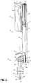
- robotic surgical system 1 includes a surgical assembly 30, which includes the instrument drive unit 100 coupled with or to robotic arm 2, and the electromechanical instrument 10 coupled to instrument drive unit 100.
- Instrument drive unit 100 transfers power and actuation forces from its motors to driven members of electromechanical instrument 10 to ultimately drive movement of components of end effector 12 of electromechanical instrument 10, for example, a movement of a knife blade (not shown) and/or a closing and opening of jaw members 14a, 14b of end effector 12.
- electromechanical instrument 10 generally includes a housing portion 16 and a shaft 18 extending distally from housing portion 16.
- Housing portion 16 has a cylindrical configuration and includes a proximal end and a distal end defining a longitudinal axis "X" therebetween.
- the proximal end of housing portion 16 defines a male mating feature 20 configured to non-rotatably engage with a female mating feature 140 ( FIG. 3 ) of instrument drive unit 100, as will be described in detail below.
- Male mating feature 20 includes a disc-shaped member 22 and a projection 24 extending proximally from disc-shaped member or flange 22.
- Projection 24 may be non-circular to non-rotatably couple to the correspondingly shaped female mating part 140 of instrument drive unit 100.
- the proximal end of housing portion 16 may be non-rotatably attached to instrument drive unit 100 via various fastening engagements, such as, for example, threaded engagement, clips, latches, friction fit engagement, buttons, a variety of fasteners, and/or a bayonet-type connection.
- the proximal end of housing portion 16 further includes a plurality of input drive couplers 26.
- Input drive couplers 26 are configured to drivingly connect to respective motors M1-M4 ( FIGS. 3 and 5 ) of instrument drive unit 100.
- Input drive couplers 26 are in the form of non-circular depressions or in the form of a crown-gear defined in the projection 24 of the male mating feature 20 of housing portion 16.
- Input drive couplers 26 are configured for non-rotatable receipt of a correspondingly shaped drive sleeve or projection (not shown) extending from each motor M1-M4.
- Housing portion 16 includes driven or force transmission members 28 that extend distally from respective input drive couplers 26.
- force transmission members 28 may be configured to convert rotational forces generated by motors M1-M4 into translational forces to actuate end effector 12.
- shaft 18 of electromechanical instrument 10 has a proximal end 30a supported by housing portion 16 and a distal end 30b having end effector 12.
- Driven members 28 extend from housing portion 16 and through shaft 18 of electromechanical instrument 10 to operably couple to various components of end effector 12 such that rotation and/or axial movement of each driven member 28 effects actuation of various functions of end effector 12.
- End effector 12 generally includes a pair of opposing jaw members 14a, 14b. End effector 12 may be moved, by actuation of driven members 28, from an open configuration wherein tissue (not shown) is received between jaw members 14a, 14b, and a closed configuration, wherein the tissue is clamped and treated.
- opposing jaw members 14a, 14b may be electrically coupled to a cable, and to a generator (not shown), via respective suitable electrical wiring 122 ( FIG. 3 ) extending through shaft 18 of electromechanical instrument 10 and through instrument drive unit 100 to provide an electrical pathway to a pair of electrically conductive, tissue-engaging sealing plates (not shown) disposed on the opposing jaw members 14a, 14b.
- surgical assembly 30 is supported on or connected to a slider 40 having a first portion 42 and a second portion 44.
- First portion 42 of slider 40 is movably connected to a track or slide 46 of robotic arm 2, and second portion 44 of slider 40 defines an opening 48 therethrough configured for frictional receipt of or connection with instrument drive unit 100.
- Slider 40 moves, slides, or translates along a longitudinal axis "Y" defined by track 46 of surgical robotic arm 2 upon a selective actuation by motor(s) (not shown) disposed in track 46 of surgical robotic arm 2 or motors (1 ... n) of control device 4.
- motor(s) not shown
- motors (1 ... n
- instrument drive unit 100 of surgical assembly 30 has a proximal end 102a and a distal end 102b configured to be operably coupled to electromechanical instrument 10 to actuate functions of end effector 12 of electromechanical instrument 10 and to rotate electromechanical instrument 10 about its longitudinal axis "X.”
- Instrument drive unit 100 may generally include an outer shell 104, a hollow core motor 110, and a plurality of motors M1-M4 ( FIGS. 3 and 5 ).
- Outer shell 104 encloses the inner components of instrument drive unit 100 to form a sterile barrier between an interior of instrument drive unit 100 and the external environment.
- Outer shell 104 may be disposable, re-usable (upon sterilization), and/or transparent.
- instrument drive unit 100 includes a proximal inner shell 112 fixedly engaged to an inner surface of outer shell 104 or non-rotatably disposed in an interior of outer shell 104.
- Hollow core motor 110 is disposed within proximal end 102a of instrument drive unit 100 and includes an outer stator 116 and an inner rotor 118.
- Outer stator 116 has a cylindrical configuration and is fixedly coupled to proximal inner shell 112, such that outer stator 116 is non-rotatable relative to outer shell 104.
- Inner rotor 118 has a cylindrical configuration and is rotatably, coaxially disposed within outer stator 116.
- Inner rotor 118 has a generally tube-like configuration having an inner surface that defines a longitudinal central channel 120 of inner rotor 118.
- Longitudinal central channel 120 of inner rotor 118 permits passage of an electrical wire 122 extending therethrough for providing electrical energy or power from a power source (e.g., a generator) to one of the plurality of motors M1-M4.
- a power source e.g., a generator
- a plurality of electrical wires extend through longitudinal central channel 120 of hollow core motor 110 to provide power to each of motors M1-M4 and/or components of end effector 12.
- Instrument drive unit 100 includes outer and inner hubs 124, 126 coaxially disposed within longitudinal channel 120 of inner rotor 118 of hollow core motor 110. Outer hub 124 is frictionally retained or keyed between inner rotor 118 of hollow core motor 110 and inner hub 126 such that outer hub 124 transmits rotational movement of inner rotor 118 to inner hub 126.
- Proximal end 102a of instrument drive unit 100 includes first and second proximal bearings 128a, 128b each disposed between outer hub 124 and proximal inner shell 112 to facilitate rotation of outer hub 124 relative to proximal inner shell 112.
- Inner hub 126 has a cylindrical portion 130 and a base flange 132. Cylindrical portion 130 of inner hub 126 is disposed within outer hub 124 and rotatable therewith. Instrument drive unit 100 further includes a distal inner shell 134 ( FIG. 3 ), which has the plurality of motors M1-M4 supported therein. Base flange 132 of inner hub 126 is connected to and is contiguous with a proximal end 136a of distal inner shell 134 such that rotational movement of inner hub 126 causes rotational movement of distal inner shell 134.
- Distal inner shell 134 unlike proximal inner shell 112, is rotatable within and relative to outer shell 104.
- Distal inner shell 134 has a distal end 136b configured to be non-rotatably coupled to the proximal end of electromechanical instrument 10 such that distal inner shell 134 transmits rotational movement of inner hub 126 to electromechanical instrument 10.
- distal end 102b of instrument drive unit 100 includes a distal cap 138 that extends distally from distal end 136b of distal inner shell 134.
- Distal cap 138 defines female mating feature 140 of instrument drive unit 100, which is configured to matingly receive male mating feature 20 of housing portion 16 of electromechanical instrument 10, as mentioned above.
- Distal end 102b of instrument drive unit 100 further includes a distal bearing 142 disposed between distal cap 138 and outer shell 104 to facilitate rotation of distal inner shell 134 and distal cap 138 relative to outer shell 104.
- instrument drive unit 100 is positioned within opening 48 defined in slider 40 to non-rotatably couple instrument drive unit 100 to surgical robotic arm 2.
- Male mating feature 20 of housing portion 16 of electromechanical instrument 100 is matingly engaged to female mating part 140 of instrument drive unit 100.
- projection 24 of male mating feature 20 of electromechanical instrument 10 non-rotatably couples to distal cap 138 of instrument drive unit 100, and input drive couplers 26 of electromechanical instrument 10 operably engage drive sleeves (not shown) extending from respective motors M1-M4 of instrument drive unit 100.
- a current is transmitted to hollow core motor 110 via a power supply (not shown).
- inner rotor 118 of hollow core motor 110 is caused to rotate relative to outer stator 116 of hollow core motor 110 and outer shell 104 of instrument drive unit 100.
- Rotation of inner rotor 118 of hollow core motor 110 rotates outer hub 124, which causes inner hub 126 to rotate due to cylindrical portion 130 of inner hub 126 being frictionally retained within outer hub 124.
- Base flange 132 of inner hub 126 is non-rotatably connected to proximal end 136a of distal inner shell 134 such that rotation of inner hub 126 effects rotation of distal inner shell 134.
- Rotation of distal inner shell 134 causes distal cap 138 to rotate therewith.
- Rotation of distal cap 138 of instrument drive unit 100 relative to outer shell 104 effects rotation of electromechanical instrument 10 about longitudinal axis "X" thereof due to distal cap 138 being non-rotatably connected to housing portion 16 of electromechanical instrument 10.
- electromechanical instrument 10 may be selectively rotated about its longitudinal axis "X" to a desired rotational position upon actuation of hollow core motor 110.
- Feedback assembly 200 is configured to determine and indicate the degree to which electromechanical instrument 10 rotates about longitudinal axis "X,” as will be described in detail below. It is contemplated that feedback assembly 200 may be configured to calculate/determine and display the amount of revolution(s) of electromechanical instrument 10, relative to instrument drive unit 100 and slider 44 about longitudinal axis "X," so that a clinician can determine the precise rotational position of electromechanical instrument 10 during use thereof.
- Feedback assembly 200 is incorporated into or associated with control circuitry "CC" ( FIG. 3 ) of the second motor 110 of instrument drive unit 100.
- Feedback assembly 200 of surgical assembly 30 includes a first annular member 210 stacked on a second annular member 220.
- Annular members 210, 220 each have a disc-shaped configuration and each define central bores having the plurality of first motors M1-M4 disposed therethrough.
- First annular member 210 is disposed concentrically within or adjacent second annular member 220 and is non-rotatably coupled to inner hub 126 of instrument drive unit 100 such that rotation of inner hub 126 results in concomitant rotation of first annular member 210.
- first annular member 210 may be integrally formed with inner hub 126 or distal cap 138 ( FIG. 3 ).
- First annular member 210 has a surface feature or tab 212 projecting radially from a circumferential edge 214 thereof.
- Surface feature 212 may have a squared configuration.
- surface feature 212 may assume a variety of shapes, such as, for example, triangular, arcuate, polygonal, uniform, non-uniform, tapered, or the like.
- Second annular member 220 may surround inner hub 126, or may be disposed adjacent (e.g., distal) inner hub 126, and is rotatable relative to inner hub 126.
- Second annular member 220 has a first surface feature or tab 222 projecting proximally from a circumferential edge 224 thereof.
- First surface feature 222 of second annular member 220 is circumferentially aligned (i.e., cocircumferential) with surface feature 212 of first annular member 210 and is circumferentially or radially spaced from surface feature 212 of first annular member 220 by a selected amount. For example, in the illustrative embodiment of FIG.
- first surface feature 222 of second annular member 220 is circumferentially spaced, in a clockwise direction, from surface feature 212 of first annular member 210 by about 360°. As such, upon a threshold amount of rotation (e.g., 360° in a counter-clockwise direction) of first annular member 210, surface feature 212 of first annular member 210 abuts or engages first surface feature 222 of second annular member 220.
- a threshold amount of rotation e.g., 360° in a counter-clockwise direction
- surface feature 212 of first annular member 210 may be resiliently biased from first annular member 210 toward a radially outward position, and first surface feature 222 of annular member 220 may have a depression formed therein.
- first annular member 210 may be rotated into radial alignment with the depression (not shown) formed in second surface feature 222 of second annular member 220, surface feature 212 of first annular member 210 biases radially outwardly into engagement with the correspondingly shaped depression (not shown) formed in second annular member 220.
- first annular member 210 clutches second annular member 220 such that second annular member 220 rotates with first annular member 210.
- Second annular member 220 has a second surface feature 224 projecting distally from circumferential edge 224 thereof. Second surface feature 224 is circumferentially spaced from first surface feature 222 by about 180°. In some embodiments, second surface feature 224 may be circumferentially spaced from first surface feature 222 by a variety of distances, such as, for example, between about 1° and about 360°, or may be radially aligned with first surface feature 222.
- Outer shell 104 has a surface feature or tab 107 extending inwardly therefrom such that upon the second annular member 220 achieving a threshold amount of rotation relative to outer shell 104, second surface feature 224 of second annular member 220 abuts or engages surface feature 107 of outer shell 104 of instrument drive unit 100 to stop rotation of inner hub 126, which stops rotation of electromechanical instrument 10 about its longitudinal axis "X.”
- feedback assembly 200 incorporates a highly toleranced resistor "R” (not shown) with an extremely low resistance, about 0.05 ohms, that is added to a low side of an H-bridge responsible for driving second motor 110.
- resistor "R” an extremely low resistance, about 0.05 ohms
- a certain or predetermined force profile is expected to be seen by feedback assembly 200 in control circuitry "CC" of electromechanical instrument 10, e.g., either a current v. time profile (not shown) or a current v. distance profile (not shown).
- an actuation of second motor 110 effects a rotation of inner hub 126 of instrument drive unit 100 as described above.
- a rotation of inner hub 126 rotates first annular member 210, via their non-rotatable connection, to ultimately place surface feature 212 of first annular member 210 into engagement with first surface feature 222 of second annular member 220.
- first annular member 210 Upon surface feature 212 of first annular member 210 engaging or coming into contact with first surface feature 222 of second annular member 220, the static inertia of second annular member 220 must be overcome by a certain threshold amount of added torque provided by second motor 110.
- the additional torque required to begin rotating second annular member 220 changes a condition of second motor 110, which is a change in current "I" delivered to second motor 110, which is a different amount of current compared to the expected force profile stored in control circuitry "CC.”
- control circuitry "CC” This increase in current "I” or current spike is registered by control circuitry "CC,” and control circuitry "CC” can reasonably assume that electromechanical instrument 10 has rotated a threshold amount from its original position.
- the current spike indicates that first annular member 210 has rotated a predetermined threshold amount (e.g., 360°) from its original rotational position. Since first annular member 210 rotates with electromechanical instrument 10, the threshold amount of rotation of first annular member 210 registered by control circuitry "CC” correlates to the same threshold amount of rotation traveled by electromechanical instrument 10 about its longitudinal axis "X.”
- display 6 FIG. 1
- display 6 may be provided to indicate, in the form of a number of degrees, the determined amount of rotation of electromechanical instrument 10.
- electromechanical instrument 10 eventually causes second surface feature 224 of second annular member 220 to abut or engage surface feature 107 of outer shell 104, which results in another current spike and an instruction to cease delivering current to second motor 110, thereby ceasing rotation of second annular member 220, and therefore electromechanical instrument 10. It is envisioned that surface feature 107 of outer shell 104 may resist or prevent further rotation of second annular member 220 due to surface feature 224 of annular member 220 mechanically engaging surface feature 107 of outer shell 104.
- feedback assembly 200 may include a single annular member or more than two annular members having any suitable number of variously spaced surface features or tabs.
- feedback assembly 200 may include three annular members stacked upon one another.
- each of the three stacked annular members may have a surface feature or tab, similar to surface features 212, 222, or 224 mentioned above, that are circumferentially spaced from one another by 180°.
- a first annular member of the three annular members upon an initial 180° rotation of inner hub 126, a first annular member of the three annular members will cause an adjacent, second annular member of the three annular members to begin to rotate, and an additional 180° rotation of inner hub 126 will cause a next adjacent, third annular member of the three annular members to begin to rotate.
- electromechanical instrument 10 is capable of rotating is directly correlated to the number of annular members being used (i.e., the greater the number of annular members that are stacked upon one another, the more electromechanical instrument 10 will be able to rotate before it is stopped).
Claims (8)
- Ensemble chirurgical (30) destiné à être utilisé avec et être relié sélectivement à un bras robotique, l'ensemble chirurgical comprenant :un instrument électromécanique (10) comportant :une partie de boîtier (16) soutenant un élément entraîné à l'intérieur de celle-ci ; etune tige (18) ayant une extrémité proximale soutenue par la partie de boîtier et une extrémité distale ayant un effecteur d'extrémité (12) accouplé de manière fonctionnelle à l'élément entraîné ; etune unité d'entraînement d'instrument (100) comportant :caractérisé en ce que l'unité d'entraînement d'instrument comprend en outre :une coque externe (104) conçue pour être accouplée sélectivement à un bras robotique ; etun moyeu interne (126) disposé de manière rotative à l'intérieur de la coque externe et conçu pour être accouplé de manière non rotative à la partie de boîtier (16) de l'instrument électromécanique ;un premier moteur (M1-M4) disposé à l'intérieur de la coque externe et conçu pour être accouplé de manière fonctionnelle à l'élément entraîné de l'instrument électromécanique ; etun second moteur (110) disposé à l'intérieur de la coque externe et comportant :un stator externe (116) accouplé de manière fixe à la coque externe ; etun rotor interne (118) disposé de manière rotative à l'intérieur du stator externe, le rotor interne ayant une surface interne qui définit un canal longitudinal (120) dans lequel le moyeu interne (126) est disposé de manière non rotative, l'actionnement du second moteur faisant tourner le moyeu interne pour effectuer une rotation de l'instrument électromécanique le long d'un axe longitudinal de celui-ci.
- Ensemble chirurgical selon la revendication 1, dans lequel l'unité d'entraînement d'instrument (100) comporte en outre un moyeu externe (124) disposé entre le rotor interne (118) et le moyeu interne (126) de sorte que le moyeu externe transmet un mouvement de rotation du rotor interne au moyeu interne.
- Ensemble chirurgical selon la revendication 2, dans lequel l'unité d'entraînement d'instrument (100) comporte en outre une coque interne (134) disposée de manière rotative à l'intérieur de la coque externe (104) et ayant une extrémité proximale (136a) accouplée au moyeu interne (126) et une extrémité distale (136b) conçue pour être accouplée à une extrémité proximale de l'instrument électromécanique (10) de sorte que la coque interne transmet un mouvement de rotation du moyeu interne à l'instrument électromécanique.
- Ensemble chirurgical selon la revendication 3, comprenant en outre un coulisseau (40) ayant une première partie (46) conçue pour être reliée de manière mobile au bras robotique et une seconde partie (44) définissant une ouverture (48) à travers celle-ci conçue pour recevoir l'unité d'entraînement d'instrument (100).
- Ensemble chirurgical selon l'une quelconque des revendications précédentes, dans lequel une extrémité distale (102b) de l'unité d'entraînement d'instrument définit un élément d'accouplement femelle (140) et une extrémité proximale de la partie de boîtier (16) de l'instrument électromécanique définit un élément d'accouplement mâle (20) conçu pour entrer en prise de manière non rotative avec l'élément d'accouplement femelle de l'unité d'entraînement d'instrument.
- Ensemble chirurgical selon l'une quelconque des revendications précédentes, dans lequel la partie de boîtier (16) comporte en outre un accoupleur d'entraînement d'entrée (26) conçu pour être accouplé par entraînement au premier moteur (M1-M4) de l'unité d'entraînement d'instrument.
- Ensemble chirurgical selon l'une quelconque des revendications précédentes, dans lequel la coque externe (104) de l'unité d'entraînement d'instrument est transparente.
- Ensemble chirurgical selon l'une quelconque des revendications précédentes, comprenant en outre un fil (122) s'étendant à travers le canal longitudinal (120) du rotor interne (118) et conçu pour transférer de l'énergie au premier moteur (M1-M4).
Applications Claiming Priority (2)
| Application Number | Priority Date | Filing Date | Title |
|---|---|---|---|
| US201562181817P | 2015-06-19 | 2015-06-19 | |
| PCT/US2016/037515 WO2016205288A1 (fr) | 2015-06-19 | 2016-06-15 | Ensembles chirurgicaux robotiques |
Publications (3)
| Publication Number | Publication Date |
|---|---|
| EP3310287A1 EP3310287A1 (fr) | 2018-04-25 |
| EP3310287A4 EP3310287A4 (fr) | 2019-02-20 |
| EP3310287B1 true EP3310287B1 (fr) | 2022-04-20 |
Family
ID=57546106
Family Applications (1)
| Application Number | Title | Priority Date | Filing Date |
|---|---|---|---|
| EP16812285.1A Active EP3310287B1 (fr) | 2015-06-19 | 2016-06-15 | Ensembles chirurgicaux robotiques |
Country Status (7)
| Country | Link |
|---|---|
| US (1) | US10675104B2 (fr) |
| EP (1) | EP3310287B1 (fr) |
| JP (1) | JP6697487B2 (fr) |
| CN (1) | CN107771063B (fr) |
| AU (1) | AU2016280014B2 (fr) |
| CA (1) | CA2987638A1 (fr) |
| WO (1) | WO2016205288A1 (fr) |
Families Citing this family (141)
| Publication number | Priority date | Publication date | Assignee | Title |
|---|---|---|---|---|
| US11871901B2 (en) | 2012-05-20 | 2024-01-16 | Cilag Gmbh International | Method for situational awareness for surgical network or surgical network connected device capable of adjusting function based on a sensed situation or usage |
| US20140005640A1 (en) | 2012-06-28 | 2014-01-02 | Ethicon Endo-Surgery, Inc. | Surgical end effector jaw and electrode configurations |
| CN105611892B (zh) * | 2013-08-15 | 2019-02-19 | 直观外科手术操作公司 | 机器人器械从动元件 |
| EP3708105B1 (fr) | 2013-08-15 | 2022-02-09 | Intuitive Surgical Operations, Inc. | Interface d'instrument chirurgical préchargé |
| WO2015023834A1 (fr) | 2013-08-15 | 2015-02-19 | Intuitive Surgical Operations, Inc. | Éléments d'entraînement d'adaptateur stérile d'instrument |
| WO2015023840A1 (fr) | 2013-08-15 | 2015-02-19 | Intuitive Surgical Operations, Inc. | Interface de commande d'adaptateur d'instrument stérile |
| US11504192B2 (en) | 2014-10-30 | 2022-11-22 | Cilag Gmbh International | Method of hub communication with surgical instrument systems |
| JP6945541B2 (ja) * | 2016-03-04 | 2021-10-06 | コヴィディエン リミテッド パートナーシップ | ロボット外科手術アセンブリ |
| WO2017205310A1 (fr) | 2016-05-26 | 2017-11-30 | Covidien Lp | Ensembles chirurgicaux robotiques |
| US11583358B2 (en) | 2017-09-06 | 2023-02-21 | Covidien Lp | Boundary scaling of surgical robots |
| US11510741B2 (en) | 2017-10-30 | 2022-11-29 | Cilag Gmbh International | Method for producing a surgical instrument comprising a smart electrical system |
| US11317919B2 (en) | 2017-10-30 | 2022-05-03 | Cilag Gmbh International | Clip applier comprising a clip crimping system |
| US11229436B2 (en) | 2017-10-30 | 2022-01-25 | Cilag Gmbh International | Surgical system comprising a surgical tool and a surgical hub |
| US11291510B2 (en) | 2017-10-30 | 2022-04-05 | Cilag Gmbh International | Method of hub communication with surgical instrument systems |
| US11801098B2 (en) | 2017-10-30 | 2023-10-31 | Cilag Gmbh International | Method of hub communication with surgical instrument systems |
| US11123070B2 (en) | 2017-10-30 | 2021-09-21 | Cilag Gmbh International | Clip applier comprising a rotatable clip magazine |
| US11564756B2 (en) | 2017-10-30 | 2023-01-31 | Cilag Gmbh International | Method of hub communication with surgical instrument systems |
| US11026712B2 (en) | 2017-10-30 | 2021-06-08 | Cilag Gmbh International | Surgical instruments comprising a shifting mechanism |
| US11311342B2 (en) | 2017-10-30 | 2022-04-26 | Cilag Gmbh International | Method for communicating with surgical instrument systems |
| US11911045B2 (en) | 2017-10-30 | 2024-02-27 | Cllag GmbH International | Method for operating a powered articulating multi-clip applier |
| US11602393B2 (en) | 2017-12-28 | 2023-03-14 | Cilag Gmbh International | Surgical evacuation sensing and generator control |
| US11056244B2 (en) | 2017-12-28 | 2021-07-06 | Cilag Gmbh International | Automated data scaling, alignment, and organizing based on predefined parameters within surgical networks |
| US11864728B2 (en) | 2017-12-28 | 2024-01-09 | Cilag Gmbh International | Characterization of tissue irregularities through the use of mono-chromatic light refractivity |
| US11069012B2 (en) | 2017-12-28 | 2021-07-20 | Cilag Gmbh International | Interactive surgical systems with condition handling of devices and data capabilities |
| US11896443B2 (en) | 2017-12-28 | 2024-02-13 | Cilag Gmbh International | Control of a surgical system through a surgical barrier |
| US11202570B2 (en) | 2017-12-28 | 2021-12-21 | Cilag Gmbh International | Communication hub and storage device for storing parameters and status of a surgical device to be shared with cloud based analytics systems |
| US11419667B2 (en) | 2017-12-28 | 2022-08-23 | Cilag Gmbh International | Ultrasonic energy device which varies pressure applied by clamp arm to provide threshold control pressure at a cut progression location |
| US11308075B2 (en) | 2017-12-28 | 2022-04-19 | Cilag Gmbh International | Surgical network, instrument, and cloud responses based on validation of received dataset and authentication of its source and integrity |
| US11432885B2 (en) | 2017-12-28 | 2022-09-06 | Cilag Gmbh International | Sensing arrangements for robot-assisted surgical platforms |
| US11540855B2 (en) | 2017-12-28 | 2023-01-03 | Cilag Gmbh International | Controlling activation of an ultrasonic surgical instrument according to the presence of tissue |
| US11857152B2 (en) | 2017-12-28 | 2024-01-02 | Cilag Gmbh International | Surgical hub spatial awareness to determine devices in operating theater |
| US11166772B2 (en) | 2017-12-28 | 2021-11-09 | Cilag Gmbh International | Surgical hub coordination of control and communication of operating room devices |
| US10944728B2 (en) | 2017-12-28 | 2021-03-09 | Ethicon Llc | Interactive surgical systems with encrypted communication capabilities |
| US11304720B2 (en) | 2017-12-28 | 2022-04-19 | Cilag Gmbh International | Activation of energy devices |
| US11633237B2 (en) | 2017-12-28 | 2023-04-25 | Cilag Gmbh International | Usage and technique analysis of surgeon / staff performance against a baseline to optimize device utilization and performance for both current and future procedures |
| US11559308B2 (en) | 2017-12-28 | 2023-01-24 | Cilag Gmbh International | Method for smart energy device infrastructure |
| US11419630B2 (en) | 2017-12-28 | 2022-08-23 | Cilag Gmbh International | Surgical system distributed processing |
| US11903601B2 (en) | 2017-12-28 | 2024-02-20 | Cilag Gmbh International | Surgical instrument comprising a plurality of drive systems |
| US10695081B2 (en) | 2017-12-28 | 2020-06-30 | Ethicon Llc | Controlling a surgical instrument according to sensed closure parameters |
| US11273001B2 (en) | 2017-12-28 | 2022-03-15 | Cilag Gmbh International | Surgical hub and modular device response adjustment based on situational awareness |
| US11076921B2 (en) | 2017-12-28 | 2021-08-03 | Cilag Gmbh International | Adaptive control program updates for surgical hubs |
| US10898622B2 (en) | 2017-12-28 | 2021-01-26 | Ethicon Llc | Surgical evacuation system with a communication circuit for communication between a filter and a smoke evacuation device |
| US11257589B2 (en) | 2017-12-28 | 2022-02-22 | Cilag Gmbh International | Real-time analysis of comprehensive cost of all instrumentation used in surgery utilizing data fluidity to track instruments through stocking and in-house processes |
| US11304745B2 (en) | 2017-12-28 | 2022-04-19 | Cilag Gmbh International | Surgical evacuation sensing and display |
| US11423007B2 (en) | 2017-12-28 | 2022-08-23 | Cilag Gmbh International | Adjustment of device control programs based on stratified contextual data in addition to the data |
| US10987178B2 (en) | 2017-12-28 | 2021-04-27 | Ethicon Llc | Surgical hub control arrangements |
| US11109866B2 (en) | 2017-12-28 | 2021-09-07 | Cilag Gmbh International | Method for circular stapler control algorithm adjustment based on situational awareness |
| US11311306B2 (en) | 2017-12-28 | 2022-04-26 | Cilag Gmbh International | Surgical systems for detecting end effector tissue distribution irregularities |
| US11234756B2 (en) | 2017-12-28 | 2022-02-01 | Cilag Gmbh International | Powered surgical tool with predefined adjustable control algorithm for controlling end effector parameter |
| US10758310B2 (en) | 2017-12-28 | 2020-09-01 | Ethicon Llc | Wireless pairing of a surgical device with another device within a sterile surgical field based on the usage and situational awareness of devices |
| US11324557B2 (en) | 2017-12-28 | 2022-05-10 | Cilag Gmbh International | Surgical instrument with a sensing array |
| US11786245B2 (en) | 2017-12-28 | 2023-10-17 | Cilag Gmbh International | Surgical systems with prioritized data transmission capabilities |
| US11559307B2 (en) | 2017-12-28 | 2023-01-24 | Cilag Gmbh International | Method of robotic hub communication, detection, and control |
| US11266468B2 (en) | 2017-12-28 | 2022-03-08 | Cilag Gmbh International | Cooperative utilization of data derived from secondary sources by intelligent surgical hubs |
| US11389164B2 (en) | 2017-12-28 | 2022-07-19 | Cilag Gmbh International | Method of using reinforced flexible circuits with multiple sensors to optimize performance of radio frequency devices |
| US20190201042A1 (en) | 2017-12-28 | 2019-07-04 | Ethicon Llc | Determining the state of an ultrasonic electromechanical system according to frequency shift |
| US11304699B2 (en) | 2017-12-28 | 2022-04-19 | Cilag Gmbh International | Method for adaptive control schemes for surgical network control and interaction |
| US11147607B2 (en) | 2017-12-28 | 2021-10-19 | Cilag Gmbh International | Bipolar combination device that automatically adjusts pressure based on energy modality |
| US11179208B2 (en) | 2017-12-28 | 2021-11-23 | Cilag Gmbh International | Cloud-based medical analytics for security and authentication trends and reactive measures |
| US10755813B2 (en) | 2017-12-28 | 2020-08-25 | Ethicon Llc | Communication of smoke evacuation system parameters to hub or cloud in smoke evacuation module for interactive surgical platform |
| US11744604B2 (en) | 2017-12-28 | 2023-09-05 | Cilag Gmbh International | Surgical instrument with a hardware-only control circuit |
| US11364075B2 (en) | 2017-12-28 | 2022-06-21 | Cilag Gmbh International | Radio frequency energy device for delivering combined electrical signals |
| US11317937B2 (en) | 2018-03-08 | 2022-05-03 | Cilag Gmbh International | Determining the state of an ultrasonic end effector |
| US10966791B2 (en) | 2017-12-28 | 2021-04-06 | Ethicon Llc | Cloud-based medical analytics for medical facility segmented individualization of instrument function |
| US11304763B2 (en) | 2017-12-28 | 2022-04-19 | Cilag Gmbh International | Image capturing of the areas outside the abdomen to improve placement and control of a surgical device in use |
| US11013563B2 (en) | 2017-12-28 | 2021-05-25 | Ethicon Llc | Drive arrangements for robot-assisted surgical platforms |
| US11937769B2 (en) | 2017-12-28 | 2024-03-26 | Cilag Gmbh International | Method of hub communication, processing, storage and display |
| US11896322B2 (en) | 2017-12-28 | 2024-02-13 | Cilag Gmbh International | Sensing the patient position and contact utilizing the mono-polar return pad electrode to provide situational awareness to the hub |
| US10943454B2 (en) | 2017-12-28 | 2021-03-09 | Ethicon Llc | Detection and escalation of security responses of surgical instruments to increasing severity threats |
| US11589888B2 (en) | 2017-12-28 | 2023-02-28 | Cilag Gmbh International | Method for controlling smart energy devices |
| US11284936B2 (en) | 2017-12-28 | 2022-03-29 | Cilag Gmbh International | Surgical instrument having a flexible electrode |
| US11672605B2 (en) | 2017-12-28 | 2023-06-13 | Cilag Gmbh International | Sterile field interactive control displays |
| US10595887B2 (en) | 2017-12-28 | 2020-03-24 | Ethicon Llc | Systems for adjusting end effector parameters based on perioperative information |
| US20190201142A1 (en) | 2017-12-28 | 2019-07-04 | Ethicon Llc | Automatic tool adjustments for robot-assisted surgical platforms |
| US10932872B2 (en) | 2017-12-28 | 2021-03-02 | Ethicon Llc | Cloud-based medical analytics for linking of local usage trends with the resource acquisition behaviors of larger data set |
| US11659023B2 (en) | 2017-12-28 | 2023-05-23 | Cilag Gmbh International | Method of hub communication |
| US11571234B2 (en) | 2017-12-28 | 2023-02-07 | Cilag Gmbh International | Temperature control of ultrasonic end effector and control system therefor |
| US11096693B2 (en) | 2017-12-28 | 2021-08-24 | Cilag Gmbh International | Adjustment of staple height of at least one row of staples based on the sensed tissue thickness or force in closing |
| US11376002B2 (en) | 2017-12-28 | 2022-07-05 | Cilag Gmbh International | Surgical instrument cartridge sensor assemblies |
| US11291495B2 (en) | 2017-12-28 | 2022-04-05 | Cilag Gmbh International | Interruption of energy due to inadvertent capacitive coupling |
| US10892995B2 (en) | 2017-12-28 | 2021-01-12 | Ethicon Llc | Surgical network determination of prioritization of communication, interaction, or processing based on system or device needs |
| US11678881B2 (en) | 2017-12-28 | 2023-06-20 | Cilag Gmbh International | Spatial awareness of surgical hubs in operating rooms |
| US11132462B2 (en) | 2017-12-28 | 2021-09-28 | Cilag Gmbh International | Data stripping method to interrogate patient records and create anonymized record |
| US11160605B2 (en) | 2017-12-28 | 2021-11-02 | Cilag Gmbh International | Surgical evacuation sensing and motor control |
| US11253315B2 (en) | 2017-12-28 | 2022-02-22 | Cilag Gmbh International | Increasing radio frequency to create pad-less monopolar loop |
| US11832899B2 (en) | 2017-12-28 | 2023-12-05 | Cilag Gmbh International | Surgical systems with autonomously adjustable control programs |
| US11818052B2 (en) | 2017-12-28 | 2023-11-14 | Cilag Gmbh International | Surgical network determination of prioritization of communication, interaction, or processing based on system or device needs |
| US11786251B2 (en) | 2017-12-28 | 2023-10-17 | Cilag Gmbh International | Method for adaptive control schemes for surgical network control and interaction |
| US11424027B2 (en) | 2017-12-28 | 2022-08-23 | Cilag Gmbh International | Method for operating surgical instrument systems |
| US10849697B2 (en) | 2017-12-28 | 2020-12-01 | Ethicon Llc | Cloud interface for coupled surgical devices |
| US11666331B2 (en) | 2017-12-28 | 2023-06-06 | Cilag Gmbh International | Systems for detecting proximity of surgical end effector to cancerous tissue |
| US10892899B2 (en) | 2017-12-28 | 2021-01-12 | Ethicon Llc | Self describing data packets generated at an issuing instrument |
| US11446052B2 (en) | 2017-12-28 | 2022-09-20 | Cilag Gmbh International | Variation of radio frequency and ultrasonic power level in cooperation with varying clamp arm pressure to achieve predefined heat flux or power applied to tissue |
| US11596291B2 (en) | 2017-12-28 | 2023-03-07 | Cilag Gmbh International | Method of compressing tissue within a stapling device and simultaneously displaying of the location of the tissue within the jaws |
| US11464535B2 (en) | 2017-12-28 | 2022-10-11 | Cilag Gmbh International | Detection of end effector emersion in liquid |
| US11051876B2 (en) | 2017-12-28 | 2021-07-06 | Cilag Gmbh International | Surgical evacuation flow paths |
| US11832840B2 (en) | 2017-12-28 | 2023-12-05 | Cilag Gmbh International | Surgical instrument having a flexible circuit |
| US11464559B2 (en) | 2017-12-28 | 2022-10-11 | Cilag Gmbh International | Estimating state of ultrasonic end effector and control system therefor |
| US11529187B2 (en) | 2017-12-28 | 2022-12-20 | Cilag Gmbh International | Surgical evacuation sensor arrangements |
| US11576677B2 (en) | 2017-12-28 | 2023-02-14 | Cilag Gmbh International | Method of hub communication, processing, display, and cloud analytics |
| US11278281B2 (en) | 2017-12-28 | 2022-03-22 | Cilag Gmbh International | Interactive surgical system |
| US11410259B2 (en) | 2017-12-28 | 2022-08-09 | Cilag Gmbh International | Adaptive control program updates for surgical devices |
| US11100631B2 (en) | 2017-12-28 | 2021-08-24 | Cilag Gmbh International | Use of laser light and red-green-blue coloration to determine properties of back scattered light |
| US11612444B2 (en) | 2017-12-28 | 2023-03-28 | Cilag Gmbh International | Adjustment of a surgical device function based on situational awareness |
| US11771487B2 (en) | 2017-12-28 | 2023-10-03 | Cilag Gmbh International | Mechanisms for controlling different electromechanical systems of an electrosurgical instrument |
| US11259830B2 (en) | 2018-03-08 | 2022-03-01 | Cilag Gmbh International | Methods for controlling temperature in ultrasonic device |
| US11678927B2 (en) | 2018-03-08 | 2023-06-20 | Cilag Gmbh International | Detection of large vessels during parenchymal dissection using a smart blade |
| US11464532B2 (en) | 2018-03-08 | 2022-10-11 | Cilag Gmbh International | Methods for estimating and controlling state of ultrasonic end effector |
| US11471156B2 (en) | 2018-03-28 | 2022-10-18 | Cilag Gmbh International | Surgical stapling devices with improved rotary driven closure systems |
| US10973520B2 (en) | 2018-03-28 | 2021-04-13 | Ethicon Llc | Surgical staple cartridge with firing member driven camming assembly that has an onboard tissue cutting feature |
| US11259806B2 (en) | 2018-03-28 | 2022-03-01 | Cilag Gmbh International | Surgical stapling devices with features for blocking advancement of a camming assembly of an incompatible cartridge installed therein |
| US11207067B2 (en) | 2018-03-28 | 2021-12-28 | Cilag Gmbh International | Surgical stapling device with separate rotary driven closure and firing systems and firing member that engages both jaws while firing |
| US11090047B2 (en) | 2018-03-28 | 2021-08-17 | Cilag Gmbh International | Surgical instrument comprising an adaptive control system |
| US11278280B2 (en) | 2018-03-28 | 2022-03-22 | Cilag Gmbh International | Surgical instrument comprising a jaw closure lockout |
| US11197668B2 (en) | 2018-03-28 | 2021-12-14 | Cilag Gmbh International | Surgical stapling assembly comprising a lockout and an exterior access orifice to permit artificial unlocking of the lockout |
| US11219453B2 (en) | 2018-03-28 | 2022-01-11 | Cilag Gmbh International | Surgical stapling devices with cartridge compatible closure and firing lockout arrangements |
| US11096688B2 (en) | 2018-03-28 | 2021-08-24 | Cilag Gmbh International | Rotary driven firing members with different anvil and channel engagement features |
| WO2020060790A1 (fr) * | 2018-09-17 | 2020-03-26 | Covidien Lp | Systèmes robotisés chirurgicaux |
| WO2020060791A1 (fr) * | 2018-09-17 | 2020-03-26 | Covidien Lp | Systèmes robotiques chirurgicaux |
| CN112702969A (zh) * | 2018-09-17 | 2021-04-23 | 柯惠Lp公司 | 手术机器人系统 |
| US11291445B2 (en) | 2019-02-19 | 2022-04-05 | Cilag Gmbh International | Surgical staple cartridges with integral authentication keys |
| US11317915B2 (en) | 2019-02-19 | 2022-05-03 | Cilag Gmbh International | Universal cartridge based key feature that unlocks multiple lockout arrangements in different surgical staplers |
| US11751872B2 (en) | 2019-02-19 | 2023-09-12 | Cilag Gmbh International | Insertable deactivator element for surgical stapler lockouts |
| US11369377B2 (en) | 2019-02-19 | 2022-06-28 | Cilag Gmbh International | Surgical stapling assembly with cartridge based retainer configured to unlock a firing lockout |
| US11357503B2 (en) | 2019-02-19 | 2022-06-14 | Cilag Gmbh International | Staple cartridge retainers with frangible retention features and methods of using same |
| USD952144S1 (en) | 2019-06-25 | 2022-05-17 | Cilag Gmbh International | Surgical staple cartridge retainer with firing system authentication key |
| USD950728S1 (en) | 2019-06-25 | 2022-05-03 | Cilag Gmbh International | Surgical staple cartridge |
| USD964564S1 (en) | 2019-06-25 | 2022-09-20 | Cilag Gmbh International | Surgical staple cartridge retainer with a closure system authentication key |
| US11547468B2 (en) | 2019-06-27 | 2023-01-10 | Cilag Gmbh International | Robotic surgical system with safety and cooperative sensing control |
| US11723729B2 (en) | 2019-06-27 | 2023-08-15 | Cilag Gmbh International | Robotic surgical assembly coupling safety mechanisms |
| US11376082B2 (en) | 2019-06-27 | 2022-07-05 | Cilag Gmbh International | Robotic surgical system with local sensing of functional parameters based on measurements of multiple physical inputs |
| US11369443B2 (en) | 2019-06-27 | 2022-06-28 | Cilag Gmbh International | Method of using a surgical modular robotic assembly |
| US11413102B2 (en) | 2019-06-27 | 2022-08-16 | Cilag Gmbh International | Multi-access port for surgical robotic systems |
| US11207146B2 (en) | 2019-06-27 | 2021-12-28 | Cilag Gmbh International | Surgical instrument drive systems with cable-tightening system |
| US11607278B2 (en) | 2019-06-27 | 2023-03-21 | Cilag Gmbh International | Cooperative robotic surgical systems |
| US11399906B2 (en) | 2019-06-27 | 2022-08-02 | Cilag Gmbh International | Robotic surgical system for controlling close operation of end-effectors |
| US11376083B2 (en) | 2019-06-27 | 2022-07-05 | Cilag Gmbh International | Determining robotic surgical assembly coupling status |
| US11612445B2 (en) | 2019-06-27 | 2023-03-28 | Cilag Gmbh International | Cooperative operation of robotic arms |
| US11278362B2 (en) | 2019-06-27 | 2022-03-22 | Cilag Gmbh International | Surgical instrument drive systems |
| US20230233277A1 (en) | 2020-06-24 | 2023-07-27 | Covidien Lp | Surgical robotic systems |
| US11931026B2 (en) | 2021-06-30 | 2024-03-19 | Cilag Gmbh International | Staple cartridge replacement |
Family Cites Families (20)
| Publication number | Priority date | Publication date | Assignee | Title |
|---|---|---|---|---|
| US4471250A (en) * | 1982-10-21 | 1984-09-11 | Emerson Electric Co. | Hub assembly for dynamoelectric machine and method of making same |
| US6132368A (en) * | 1996-12-12 | 2000-10-17 | Intuitive Surgical, Inc. | Multi-component telepresence system and method |
| US9261172B2 (en) | 2004-09-30 | 2016-02-16 | Intuitive Surgical Operations, Inc. | Multi-ply strap drive trains for surgical robotic arms |
| US9096033B2 (en) * | 2007-06-13 | 2015-08-04 | Intuitive Surgical Operations, Inc. | Surgical system instrument sterile adapter |
| US8517241B2 (en) | 2010-04-16 | 2013-08-27 | Covidien Lp | Hand-held surgical devices |
| US8109956B2 (en) * | 2008-03-07 | 2012-02-07 | Medtronic Xomed, Inc. | Systems and methods for surgical removal of tissue |
| WO2009151205A1 (fr) | 2008-06-11 | 2009-12-17 | (주)미래컴퍼니 | Instrument de bras de robot chirurgical |
| CN201256952Y (zh) * | 2008-07-11 | 2009-06-17 | 贾罗琦 | 一种使内窥镜探头旋转窥视的线操纵装置 |
| US8786233B2 (en) * | 2011-04-27 | 2014-07-22 | Medtronic Xomed, Inc. | Electric ratchet for a powered screwdriver |
| US8968312B2 (en) * | 2011-11-16 | 2015-03-03 | Covidien Lp | Surgical device with powered articulation wrist rotation |
| US8894647B2 (en) * | 2012-01-13 | 2014-11-25 | Covidien Lp | System and method for performing surgical procedures with a reusable instrument module |
| US9241757B2 (en) * | 2012-01-13 | 2016-01-26 | Covidien Lp | System and method for performing surgical procedures with a reusable instrument module |
| EP2626010B1 (fr) * | 2012-02-10 | 2015-08-26 | W & H Dentalwerk Bürmoos GmbH | Instrument médical, notamment dentaire ou chirurgical, avec revêtement |
| EP2811932B1 (fr) * | 2012-02-10 | 2019-06-26 | Ethicon LLC | Instrument chirurgical robotisé |
| KR102255640B1 (ko) * | 2012-06-01 | 2021-05-25 | 인튜어티브 서지컬 오퍼레이션즈 인코포레이티드 | 수술 시스템용 기구 캐리지 어셈블리 |
| US20140249557A1 (en) * | 2013-03-01 | 2014-09-04 | Ethicon Endo-Surgery, Inc. | Thumbwheel switch arrangements for surgical instruments |
| US9808244B2 (en) * | 2013-03-14 | 2017-11-07 | Ethicon Llc | Sensor arrangements for absolute positioning system for surgical instruments |
| JP6426181B2 (ja) * | 2013-08-15 | 2018-11-21 | インテュイティブ サージカル オペレーションズ, インコーポレイテッド | 可変器具予荷重機構コントローラ |
| JP6150672B2 (ja) * | 2013-08-26 | 2017-06-21 | オリンパス株式会社 | 医療用マニピュレータ |
| CN104116547B (zh) * | 2014-07-25 | 2016-04-06 | 上海交通大学 | 用于微创手术机器人的低摩擦小惯量手术器械 |
-
2016
- 2016-06-15 US US15/736,050 patent/US10675104B2/en active Active
- 2016-06-15 WO PCT/US2016/037515 patent/WO2016205288A1/fr active Application Filing
- 2016-06-15 JP JP2017564879A patent/JP6697487B2/ja not_active Expired - Fee Related
- 2016-06-15 EP EP16812285.1A patent/EP3310287B1/fr active Active
- 2016-06-15 AU AU2016280014A patent/AU2016280014B2/en not_active Ceased
- 2016-06-15 CA CA2987638A patent/CA2987638A1/fr active Pending
- 2016-06-15 CN CN201680034659.6A patent/CN107771063B/zh active Active
Also Published As
| Publication number | Publication date |
|---|---|
| US10675104B2 (en) | 2020-06-09 |
| EP3310287A4 (fr) | 2019-02-20 |
| AU2016280014B2 (en) | 2020-07-09 |
| JP2018518280A (ja) | 2018-07-12 |
| CN107771063A (zh) | 2018-03-06 |
| CA2987638A1 (fr) | 2016-12-22 |
| EP3310287A1 (fr) | 2018-04-25 |
| WO2016205288A1 (fr) | 2016-12-22 |
| JP6697487B2 (ja) | 2020-05-20 |
| US20180168748A1 (en) | 2018-06-21 |
| AU2016280014A1 (en) | 2017-12-07 |
| CN107771063B (zh) | 2020-12-04 |
Similar Documents
| Publication | Publication Date | Title |
|---|---|---|
| EP3310287B1 (fr) | Ensembles chirurgicaux robotiques | |
| US11219494B2 (en) | Robotic surgical assemblies | |
| US20230414304A1 (en) | Robotic surgical assemblies | |
| BR112013030549B1 (pt) | instrumento cirúrgico | |
| US20180161110A1 (en) | Surgical Tool and Robotic Surgical System Interfaces | |
| US20180161111A1 (en) | Surgical Tool and Robotic Surgical System Interfaces | |
| US20220125529A1 (en) | Surgical robotic systems | |
| US20210220063A1 (en) | Surgical robotic systems | |
| US20210338347A1 (en) | Surgical robotic systems | |
| US20210212786A1 (en) | Surgical robotic systems |
Legal Events
| Date | Code | Title | Description |
|---|---|---|---|
| STAA | Information on the status of an ep patent application or granted ep patent |
Free format text: STATUS: THE INTERNATIONAL PUBLICATION HAS BEEN MADE |
|
| PUAI | Public reference made under article 153(3) epc to a published international application that has entered the european phase |
Free format text: ORIGINAL CODE: 0009012 |
|
| STAA | Information on the status of an ep patent application or granted ep patent |
Free format text: STATUS: REQUEST FOR EXAMINATION WAS MADE |
|
| 17P | Request for examination filed |
Effective date: 20180118 |
|
| AK | Designated contracting states |
Kind code of ref document: A1 Designated state(s): AL AT BE BG CH CY CZ DE DK EE ES FI FR GB GR HR HU IE IS IT LI LT LU LV MC MK MT NL NO PL PT RO RS SE SI SK SM TR |
|
| AX | Request for extension of the european patent |
Extension state: BA ME |
|
| RIN1 | Information on inventor provided before grant (corrected) |
Inventor name: KAPADIA, JAIMEEN |
|
| DAV | Request for validation of the european patent (deleted) | ||
| DAX | Request for extension of the european patent (deleted) | ||
| A4 | Supplementary search report drawn up and despatched |
Effective date: 20190121 |
|
| RIC1 | Information provided on ipc code assigned before grant |
Ipc: A61B 17/29 20060101ALI20190115BHEP Ipc: A61B 34/00 20160101ALI20190115BHEP Ipc: A61B 34/30 20160101AFI20190115BHEP Ipc: A61B 17/00 20060101ALI20190115BHEP |
|
| GRAP | Despatch of communication of intention to grant a patent |
Free format text: ORIGINAL CODE: EPIDOSNIGR1 |
|
| STAA | Information on the status of an ep patent application or granted ep patent |
Free format text: STATUS: GRANT OF PATENT IS INTENDED |
|
| INTG | Intention to grant announced |
Effective date: 20211210 |
|
| GRAS | Grant fee paid |
Free format text: ORIGINAL CODE: EPIDOSNIGR3 |
|
| GRAA | (expected) grant |
Free format text: ORIGINAL CODE: 0009210 |
|
| STAA | Information on the status of an ep patent application or granted ep patent |
Free format text: STATUS: THE PATENT HAS BEEN GRANTED |
|
| AK | Designated contracting states |
Kind code of ref document: B1 Designated state(s): AL AT BE BG CH CY CZ DE DK EE ES FI FR GB GR HR HU IE IS IT LI LT LU LV MC MK MT NL NO PL PT RO RS SE SI SK SM TR |
|
| REG | Reference to a national code |
Ref country code: GB Ref legal event code: FG4D |
|
| REG | Reference to a national code |
Ref country code: CH Ref legal event code: EP |
|
| REG | Reference to a national code |
Ref country code: DE Ref legal event code: R096 Ref document number: 602016071350 Country of ref document: DE |
|
| REG | Reference to a national code |
Ref country code: IE Ref legal event code: FG4D |
|
| REG | Reference to a national code |
Ref country code: AT Ref legal event code: REF Ref document number: 1484582 Country of ref document: AT Kind code of ref document: T Effective date: 20220515 |
|
| REG | Reference to a national code |
Ref country code: LT Ref legal event code: MG9D |
|
| REG | Reference to a national code |
Ref country code: NL Ref legal event code: MP Effective date: 20220420 |
|
| REG | Reference to a national code |
Ref country code: AT Ref legal event code: MK05 Ref document number: 1484582 Country of ref document: AT Kind code of ref document: T Effective date: 20220420 |
|
| PG25 | Lapsed in a contracting state [announced via postgrant information from national office to epo] |
Ref country code: NL Free format text: LAPSE BECAUSE OF FAILURE TO SUBMIT A TRANSLATION OF THE DESCRIPTION OR TO PAY THE FEE WITHIN THE PRESCRIBED TIME-LIMIT Effective date: 20220420 |
|
| PG25 | Lapsed in a contracting state [announced via postgrant information from national office to epo] |
Ref country code: SE Free format text: LAPSE BECAUSE OF FAILURE TO SUBMIT A TRANSLATION OF THE DESCRIPTION OR TO PAY THE FEE WITHIN THE PRESCRIBED TIME-LIMIT Effective date: 20220420 Ref country code: PT Free format text: LAPSE BECAUSE OF FAILURE TO SUBMIT A TRANSLATION OF THE DESCRIPTION OR TO PAY THE FEE WITHIN THE PRESCRIBED TIME-LIMIT Effective date: 20220822 Ref country code: NO Free format text: LAPSE BECAUSE OF FAILURE TO SUBMIT A TRANSLATION OF THE DESCRIPTION OR TO PAY THE FEE WITHIN THE PRESCRIBED TIME-LIMIT Effective date: 20220720 Ref country code: LT Free format text: LAPSE BECAUSE OF FAILURE TO SUBMIT A TRANSLATION OF THE DESCRIPTION OR TO PAY THE FEE WITHIN THE PRESCRIBED TIME-LIMIT Effective date: 20220420 Ref country code: HR Free format text: LAPSE BECAUSE OF FAILURE TO SUBMIT A TRANSLATION OF THE DESCRIPTION OR TO PAY THE FEE WITHIN THE PRESCRIBED TIME-LIMIT Effective date: 20220420 Ref country code: GR Free format text: LAPSE BECAUSE OF FAILURE TO SUBMIT A TRANSLATION OF THE DESCRIPTION OR TO PAY THE FEE WITHIN THE PRESCRIBED TIME-LIMIT Effective date: 20220721 Ref country code: FI Free format text: LAPSE BECAUSE OF FAILURE TO SUBMIT A TRANSLATION OF THE DESCRIPTION OR TO PAY THE FEE WITHIN THE PRESCRIBED TIME-LIMIT Effective date: 20220420 Ref country code: ES Free format text: LAPSE BECAUSE OF FAILURE TO SUBMIT A TRANSLATION OF THE DESCRIPTION OR TO PAY THE FEE WITHIN THE PRESCRIBED TIME-LIMIT Effective date: 20220420 Ref country code: BG Free format text: LAPSE BECAUSE OF FAILURE TO SUBMIT A TRANSLATION OF THE DESCRIPTION OR TO PAY THE FEE WITHIN THE PRESCRIBED TIME-LIMIT Effective date: 20220720 Ref country code: AT Free format text: LAPSE BECAUSE OF FAILURE TO SUBMIT A TRANSLATION OF THE DESCRIPTION OR TO PAY THE FEE WITHIN THE PRESCRIBED TIME-LIMIT Effective date: 20220420 |
|
| PG25 | Lapsed in a contracting state [announced via postgrant information from national office to epo] |
Ref country code: RS Free format text: LAPSE BECAUSE OF FAILURE TO SUBMIT A TRANSLATION OF THE DESCRIPTION OR TO PAY THE FEE WITHIN THE PRESCRIBED TIME-LIMIT Effective date: 20220420 Ref country code: PL Free format text: LAPSE BECAUSE OF FAILURE TO SUBMIT A TRANSLATION OF THE DESCRIPTION OR TO PAY THE FEE WITHIN THE PRESCRIBED TIME-LIMIT Effective date: 20220420 Ref country code: LV Free format text: LAPSE BECAUSE OF FAILURE TO SUBMIT A TRANSLATION OF THE DESCRIPTION OR TO PAY THE FEE WITHIN THE PRESCRIBED TIME-LIMIT Effective date: 20220420 Ref country code: IS Free format text: LAPSE BECAUSE OF FAILURE TO SUBMIT A TRANSLATION OF THE DESCRIPTION OR TO PAY THE FEE WITHIN THE PRESCRIBED TIME-LIMIT Effective date: 20220820 |
|
| REG | Reference to a national code |
Ref country code: DE Ref legal event code: R097 Ref document number: 602016071350 Country of ref document: DE |
|
| PG25 | Lapsed in a contracting state [announced via postgrant information from national office to epo] |
Ref country code: SM Free format text: LAPSE BECAUSE OF FAILURE TO SUBMIT A TRANSLATION OF THE DESCRIPTION OR TO PAY THE FEE WITHIN THE PRESCRIBED TIME-LIMIT Effective date: 20220420 Ref country code: SK Free format text: LAPSE BECAUSE OF FAILURE TO SUBMIT A TRANSLATION OF THE DESCRIPTION OR TO PAY THE FEE WITHIN THE PRESCRIBED TIME-LIMIT Effective date: 20220420 Ref country code: RO Free format text: LAPSE BECAUSE OF FAILURE TO SUBMIT A TRANSLATION OF THE DESCRIPTION OR TO PAY THE FEE WITHIN THE PRESCRIBED TIME-LIMIT Effective date: 20220420 Ref country code: MC Free format text: LAPSE BECAUSE OF FAILURE TO SUBMIT A TRANSLATION OF THE DESCRIPTION OR TO PAY THE FEE WITHIN THE PRESCRIBED TIME-LIMIT Effective date: 20220420 Ref country code: EE Free format text: LAPSE BECAUSE OF FAILURE TO SUBMIT A TRANSLATION OF THE DESCRIPTION OR TO PAY THE FEE WITHIN THE PRESCRIBED TIME-LIMIT Effective date: 20220420 Ref country code: DK Free format text: LAPSE BECAUSE OF FAILURE TO SUBMIT A TRANSLATION OF THE DESCRIPTION OR TO PAY THE FEE WITHIN THE PRESCRIBED TIME-LIMIT Effective date: 20220420 Ref country code: CZ Free format text: LAPSE BECAUSE OF FAILURE TO SUBMIT A TRANSLATION OF THE DESCRIPTION OR TO PAY THE FEE WITHIN THE PRESCRIBED TIME-LIMIT Effective date: 20220420 |
|
| REG | Reference to a national code |
Ref country code: CH Ref legal event code: PL |
|
| REG | Reference to a national code |
Ref country code: BE Ref legal event code: MM Effective date: 20220630 |
|
| PLBE | No opposition filed within time limit |
Free format text: ORIGINAL CODE: 0009261 |
|
| STAA | Information on the status of an ep patent application or granted ep patent |
Free format text: STATUS: NO OPPOSITION FILED WITHIN TIME LIMIT |
|
| 26N | No opposition filed |
Effective date: 20230123 |
|
| PG25 | Lapsed in a contracting state [announced via postgrant information from national office to epo] |
Ref country code: AL Free format text: LAPSE BECAUSE OF FAILURE TO SUBMIT A TRANSLATION OF THE DESCRIPTION OR TO PAY THE FEE WITHIN THE PRESCRIBED TIME-LIMIT Effective date: 20220420 |
|
| PG25 | Lapsed in a contracting state [announced via postgrant information from national office to epo] |
Ref country code: LU Free format text: LAPSE BECAUSE OF NON-PAYMENT OF DUE FEES Effective date: 20220615 Ref country code: LI Free format text: LAPSE BECAUSE OF NON-PAYMENT OF DUE FEES Effective date: 20220630 Ref country code: IE Free format text: LAPSE BECAUSE OF NON-PAYMENT OF DUE FEES Effective date: 20220615 Ref country code: FR Free format text: LAPSE BECAUSE OF NON-PAYMENT OF DUE FEES Effective date: 20220620 Ref country code: CH Free format text: LAPSE BECAUSE OF NON-PAYMENT OF DUE FEES Effective date: 20220630 |
|
| PG25 | Lapsed in a contracting state [announced via postgrant information from national office to epo] |
Ref country code: SI Free format text: LAPSE BECAUSE OF FAILURE TO SUBMIT A TRANSLATION OF THE DESCRIPTION OR TO PAY THE FEE WITHIN THE PRESCRIBED TIME-LIMIT Effective date: 20220420 Ref country code: BE Free format text: LAPSE BECAUSE OF NON-PAYMENT OF DUE FEES Effective date: 20220630 |
|
| PGFP | Annual fee paid to national office [announced via postgrant information from national office to epo] |
Ref country code: DE Payment date: 20230523 Year of fee payment: 8 |
|
| PGFP | Annual fee paid to national office [announced via postgrant information from national office to epo] |
Ref country code: GB Payment date: 20230523 Year of fee payment: 8 |
|
| PG25 | Lapsed in a contracting state [announced via postgrant information from national office to epo] |
Ref country code: IT Free format text: LAPSE BECAUSE OF FAILURE TO SUBMIT A TRANSLATION OF THE DESCRIPTION OR TO PAY THE FEE WITHIN THE PRESCRIBED TIME-LIMIT Effective date: 20220420 |
|
| PG25 | Lapsed in a contracting state [announced via postgrant information from national office to epo] |
Ref country code: HU Free format text: LAPSE BECAUSE OF FAILURE TO SUBMIT A TRANSLATION OF THE DESCRIPTION OR TO PAY THE FEE WITHIN THE PRESCRIBED TIME-LIMIT; INVALID AB INITIO Effective date: 20160615 |