EP3310124A1 - Base station, management device, and connection method - Google Patents
Base station, management device, and connection method Download PDFInfo
- Publication number
- EP3310124A1 EP3310124A1 EP16835228.4A EP16835228A EP3310124A1 EP 3310124 A1 EP3310124 A1 EP 3310124A1 EP 16835228 A EP16835228 A EP 16835228A EP 3310124 A1 EP3310124 A1 EP 3310124A1
- Authority
- EP
- European Patent Office
- Prior art keywords
- management apparatus
- user equipment
- base station
- reroute
- mme
- Prior art date
- Legal status (The legal status is an assumption and is not a legal conclusion. Google has not performed a legal analysis and makes no representation as to the accuracy of the status listed.)
- Granted
Links
Images






Classifications
-
- H—ELECTRICITY
- H04—ELECTRIC COMMUNICATION TECHNIQUE
- H04W—WIRELESS COMMUNICATION NETWORKS
- H04W8/00—Network data management
- H04W8/02—Processing of mobility data, e.g. registration information at HLR [Home Location Register] or VLR [Visitor Location Register]; Transfer of mobility data, e.g. between HLR, VLR or external networks
- H04W8/08—Mobility data transfer
- H04W8/12—Mobility data transfer between location registers or mobility servers
-
- H—ELECTRICITY
- H04—ELECTRIC COMMUNICATION TECHNIQUE
- H04W—WIRELESS COMMUNICATION NETWORKS
- H04W92/00—Interfaces specially adapted for wireless communication networks
- H04W92/04—Interfaces between hierarchically different network devices
- H04W92/14—Interfaces between hierarchically different network devices between access point controllers and backbone network device
-
- H—ELECTRICITY
- H04—ELECTRIC COMMUNICATION TECHNIQUE
- H04W—WIRELESS COMMUNICATION NETWORKS
- H04W48/00—Access restriction; Network selection; Access point selection
- H04W48/02—Access restriction performed under specific conditions
-
- H—ELECTRICITY
- H04—ELECTRIC COMMUNICATION TECHNIQUE
- H04W—WIRELESS COMMUNICATION NETWORKS
- H04W8/00—Network data management
- H04W8/02—Processing of mobility data, e.g. registration information at HLR [Home Location Register] or VLR [Visitor Location Register]; Transfer of mobility data, e.g. between HLR, VLR or external networks
-
- H—ELECTRICITY
- H04—ELECTRIC COMMUNICATION TECHNIQUE
- H04W—WIRELESS COMMUNICATION NETWORKS
- H04W88/00—Devices specially adapted for wireless communication networks, e.g. terminals, base stations or access point devices
- H04W88/18—Service support devices; Network management devices
-
- H—ELECTRICITY
- H04—ELECTRIC COMMUNICATION TECHNIQUE
- H04W—WIRELESS COMMUNICATION NETWORKS
- H04W88/00—Devices specially adapted for wireless communication networks, e.g. terminals, base stations or access point devices
- H04W88/18—Service support devices; Network management devices
- H04W88/182—Network node acting on behalf of an other network entity, e.g. proxy
Definitions
- the present invention relates to a radio communication system.
- an M2M dedicated EPC for M2M users is provided in the DECOR.
- a base station evolved NodeB: eNB
- user equipment UE
- Attach/TAU Track Area Update
- the base station Upon receiving the Attach/TAU, the base station transmits the Attach/TAU to an existing EPC serving as a default CN.
- the existing EPC Upon receiving the Attach/TAU, the existing EPC transmits an Updated Location Request (ULR) to an IPSCP (IP Service Control Point) or an HSS (Home Subscriber Server).
- ULR Updated Location Request
- IPSCP IP Service Control Point
- HSS Home Subscriber Server
- the IPSCP or the HSS returns an Update Location Answer (ULA) to indicate subscription information (user information, an APN (Access Point Name), an UE type (UE Usage Type) or the like) on the user equipment to the existing EPC.
- UAA Update Location Answer
- the existing EPC determines the UE type from the received subscription information and redirects the Attach/TAU corresponding to the determined UE type. Specifically, the existing EPC determines whether the user equipment is the general user or the M2M user based on the UE type. If the UE type is the general user, the existing EPC accommodates the user equipment. On the other hand, if the UE type is the M2M user, the existing EPC redirects the Attach/TAU to an M2M dedicated EPC (dedicated CN).
- M2M dedicated EPC dedicated CN
- the M2M terminals can be allocated to resources for the dedicated core network, and there are some merits where functions and/or resources to be possessed by the dedicated core network can be efficiently introduced.
- a base station redirects a NAS (Non Access Stratum) message to an M2M dedicated EPC based on Dedicated MMEGI (Mobility Management Entity Group Identity).
- NAS Non Access Stratum
- MME Mobile Management Entity
- the base station upon receiving a connection request from user equipment, the base station selects an MME (Mobility Management Entity) for the user equipment.
- GUMMEI Globally Unique MME Identity
- PLMN Public Land Mobile Network
- the base station uses a S-TMSI (SAE Temporary Mobile Subscriber Identity) included in an RRC Connection Request to restore the connection to the relevant MME.
- S-TMSI SAE Temporary Mobile Subscriber Identity
- the user equipment first transmits an RRC Connection Request including the S-TMSI to the base station.
- the base station receives an RRC Connection Setup Complete including a Registered MME and a Selected PLMN from the user equipment.
- the base station Upon receiving the RRC Connection Setup Complete, the base station performs the NNSF and transmits an Initial UE Message to MME#1 corresponding to the Registered MME.
- the MME#1 exchanges an Initial Context Setup Request or an Initial Context Setup Response with the base station, and an S1 Connection for the relevant UE will be established between the base station and the MME#L.
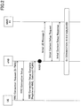
- the DECOR applied NNSF may follow a procedure as illustrated in FIG. 3 .
- the base station upon receiving an RRC Connection Setup Complete from the user equipment, transmits an Initial UE Message including a NAS PDU to the MME#1.
- the MME#1 Upon receiving the Initial UE Message, transmits an Identification Request to MME#2 interacting with the user equipment in a previous session.
- the MME#2 Upon receiving the Identification Request, the MME#2 returns an Identification Response including an UE Usage Type of the user equipment.
- the MME#1 transmits a DL (Downlink) NAS TRANSPORT including a NAS PDU (Packet Data Unit) and an MMEGI to the base station to redirect the user equipment to the M2M MME.
- a DL (Downlink) NAS TRANSPORT including a NAS PDU (Packet Data Unit) and an MMEGI to the base station to redirect the user equipment to the M2M MME.
- the base station Upon receiving the DL NAS TRANSPORT, the base station transmits an Initial UE Message to the M2M MME corresponding to the MMEGI and exchanges the Initial Context Setup Request and the Initial Context Setup Response with the M2M MME.
- the S1 Connection for the relevant UE is established between the base station and the M2M MME.
- the procedure for rerouting the NAS message incoming from the MME#1 to the M2M MME is performed in the DL NAS TRANSPORT
- an S1AP ID for uniquely identifying the user equipment in an S1 interface I/F
- the MME UE S1AP ID is essentially set in the DL NAS TRANSPORT, and accordingly the MME will set the MME UE S1AP IE.
- eNB UE S1AP ID#1 in the illustrated example a pair of the eNB UE S1AP ID (eNB UE S1AP ID#1 in the illustrated example) for identifying the user equipment at the base station and the MME UE S1AP ID (MME UE S1AP ID#A in the illustrated example) is established.
- the base station transmits an Initial UE Message to the reroute destination M2M MME at the next timing, the base station must reassign another eNB UE S1AP ID (eNB UE S1AP ID#2 in the illustrated example) at that timing.
- the pair of the eNB UE S1AP ID#1 and the MME UE S1AP ID#A is deleted without substantial use, and an S1 Connection will be established with the pair of the eNB UE S1AP ID#2 and the MME UE S1AP ID#X.
- an object of the present invention is to provide techniques for establishing connection to the reroute destination MME without setting any unnecessary identifier.
- one aspect of the present invention relates to a base station, comprising: a connection request processing unit configured to, upon receiving a connection request from user equipment, perform a connection operation on the user equipment; and a core network connection unit configured to, upon receiving a reroute message to indicate a reroute from a first management apparatus to a second management apparatus, transmit NAS (Non Access Stratum) information in the reroute message to the second management apparatus without establishing an S1 connection for the first management apparatus and the user equipment.
- NAS Non Access Stratum
- a management apparatus comprising: a user type determination unit configured to, upon receiving a connection request of user equipment from a base station, determine a type of the user equipment; and a reroute processing unit configured to perform a reroute operation to accommodate the user equipment in another management apparatus corresponding to the type of the user equipment, wherein the reroute processing unit transmits a reroute message to the base station without providing an identifier of the user equipment by the management apparatus, the reroute message including NAS (Non Access Stratum) information to connect to the other management apparatus.
- NAS Non Access Stratum
- a still further aspect of the present invention relates to a connection method for connecting user equipment to a core network, the method comprising: receiving, by a base station, a connection request from user equipment; selecting, by the base station, a management apparatus to accommodate the user equipment based on the received connection request; transmitting, by the base station, the connection request for the user equipment to the selected management apparatus; determining, by the selected management apparatus, a type of the user equipment; and performing, by the selected management apparatus, a reroute operation to accommodate the user equipment in another management apparatus corresponding to the type of the user equipment, wherein the performing the reroute operation includes transmitting a reroute message to the base station without providing an identifier of the user equipment by the selected management apparatus, the reroute message including NAS (Non Access Stratum) information to connect to the other management apparatus.
- NAS Non Access Stratum
- a base station (eNB) and a management apparatus (MME) to connect user equipment to a core network in the DECOR are disclosed.
- the reroute source management apparatus indicates the reroute to the base station without providing an identifier (MME UE S1AP ID) for identifying the UE.
- the base station does not have to reconfigure an identifier (eNB UE S1AP ID) corresponding to the UE identifier (MME UE S1AP ID) assigned by the reroute source management apparatus and can reuse the already configured identifier (eNB UE S1AP ID) for the reroute source management apparatus to establish connection (S1 Connection) to the reroute destination management apparatus.
- eNB UE S1AP ID an identifier corresponding to the UE identifier assigned by the reroute source management apparatus and can reuse the already configured identifier (eNB UE S1AP ID) for the reroute source management apparatus to establish connection (S1 Connection) to the reroute destination management apparatus.
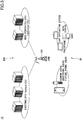
- FIG. 5 is a schematic diagram for illustrating a radio communication system according to one embodiment of the present invention.
- the radio communication system 10 has user equipment 50, a base station (eNB) 100 and a management apparatus (EPC) 200.
- the radio communication system 10 may be an LTE system or an LTE-Advanced system.
- only the single base station 100 is illustrated, but a large number of base stations 100 are disposed to cover a service area of the radio communication system 10.
- the user equipment 50 communicates with the base station 100 via a cell served by the base station 100.
- the user equipment 50 may be any appropriate information processing apparatus having a radio communication function such as a smartphone, a cellular phone, a tablet, a mobile router, a wearable terminal, a smart meter, a sensor, a photo frame, a car navigation system and a gaming device.
- the user equipment 50 is classified into a general user such as a cellular phone and a smartphone and an M2M user such as a smart meter and a sensor. In general, communication by the general user is prioritized over communication by the M2M user.
- the base station 100 wirelessly connects to the user equipment 50 to transmit a downlink (DL) packet received from various network devices via the management apparatus 200 and an uplink (UL) packet received from the user equipment 50 to the network devices.
- DL downlink
- UL uplink
- the base station 100 upon receiving a connection request from the user equipment 50, the base station 100 performs a core node selection function (NNSF) to select the management apparatus 200 to accommodate the user equipment 50 based on the received connection request and transmits an Initial UE Message including the eNB UE S1AP ID to the selected management apparatus 200.
- NSF core node selection function
- the base station 100 is typically arranged with hardware resources such as an antenna for transmitting and receiving radio signals to/from the user equipment 50, a communication interface (X2 interface or the like) for communicating with adjacent base stations 100, a communication interface (S1 interface or the like) for communicating with the management apparatus 200 and a processor and/or a circuit for processing signals transmitted and received to/from the user equipment 50 and the management apparatus 200.
- hardware resources such as an antenna for transmitting and receiving radio signals to/from the user equipment 50, a communication interface (X2 interface or the like) for communicating with adjacent base stations 100, a communication interface (S1 interface or the like) for communicating with the management apparatus 200 and a processor and/or a circuit for processing signals transmitted and received to/from the user equipment 50 and the management apparatus 200.
- Functions and operations of the base station 100 as stated below may be implemented by the processor processing or executing data and/or programs stored in a memory device.
- the base station 100 is not limited to the above-stated hardware arrangement and may have any other appropriate hardware arrangement.
- the management apparatus 200 composes a core network including an EPC and an MME.
- the base station 100 and the management apparatus 200 support the DECOR.
- the management apparatus 200 determines the type of the user equipment 50 in response to a connection request such as an Attach/TAU and a Service Request of the user equipment 50 received from the base station 100.
- a connection request such as an Attach/TAU and a Service Request of the user equipment 50 received from the base station 100.
- the general user is accommodated in the default management apparatus 200
- the M2M user is accommodated in the M2M dedicated management apparatus 200.
- the management apparatus 200 is typically implemented with a server or the like, and functions and operations of the management apparatus 200 as stated below may be implemented by the processor processing or executing data and/or programs stored in the memory device.
- the management apparatus 200 is not limited to the above-stated hardware arrangement and may have any other appropriate hardware arrangement.
- FIG. 6 is a sequence diagram for illustrating the DECOR applied NNSF procedure according to one embodiment of the present invention.
- a connection operation is performed between the user equipment 50 and the base station 100 via exchanges of an RRC Connection Setup and an RRC Connection Setup Complete.
- the base station 100 performs an NNSF based on an S-TMSI included in the RRC Connection Request or a Registered MME and a Selected PLMN included in the RRC Connection Setup Complete to determine a management apparatus 201 (New MME#1) to accommodate the user equipment 50.
- the base station 100 transmits an Initial UE Message including an eNB UE S1AP ID to the management apparatus 201.
- the management apparatus 201 identifies the user equipment 50 based on the received Initial UE Message.
- the management apparatus 201 identifies that the user equipment 50 has been accommodated in a management apparatus 202 (Old MME#2) in a previous session and transmits an Identification Request to the management apparatus 202.
- the management apparatus 202 Upon receiving the Identification Request, the management apparatus 202 returns an Identification Response including an UE Usage Type indicative of a type of the user equipment 50 to the management apparatus 201.
- the management apparatus 201 identifies the type of the user equipment 50 to apply the DECOR and determines the management apparatus 200 to accommodate the user equipment 50 corresponding to the identified type. In the illustrated example, it is determined that the user equipment 50 is an M2M user, and the management apparatus 201 selects a management apparatus 203 (Second MME) as the management apparatus 200 to accommodate the user equipment 50 and transmits an NAS Rerouting Command to the base station 100 to redirect the connection request to the management apparatus 203.
- DL NAS TRANSPORT is performed, and the eNB UE S1AP ID is reconfigured corresponding to the MME UE S1AP ID provided in the DL NAS TRANSPORT.
- the management apparatus 201 uses the eNB UE S1AP ID included in the Initial UE Message received at step S104 to transmit the NAS Rerouting Command to the base station 100 without providing the MME UE S1AP ID.
- the base station 100 does not have to configure any new eNB UE S1AP ID corresponding to the MME UE S1AP ID.
- the management apparatus 201 transmits a reroute message (NAS MESSAGE REROUTE) to the base station 100 to indicate a reroute from the management apparatus 201 to the management apparatus 203 including the NAS information to connect to the management apparatus 203 without providing an identifier (MME S1AP ID) of the user equipment 50.
- NAS MESSAGE REROUTE a reroute message
- MME S1AP ID an identifier
- the base station 100 transmits the Initial UE Message including the already configured eNB UE S1AP ID to the management apparatus 203 without configuring any new eNB UE S1AP ID to exchange an Initial Context Setup Request and an Initial Context Setup Response.
- an S1 Connection is established between the base station 100 and the management apparatus 203, and the eNB UE S1AP ID configured at step S104 will be associated with the MME UE S1AP ID provided by the management apparatus 203.
- the NAS MESSAGE REROUTE is transmitted by the management apparatus 201 and is used to indicate to the base station 100 that the NAS information has to be rerouted to the management apparatus 203.
- the NAS MESSAGE REROUTE may essentially include information elements (IEs) of Message Type, eNB UE S1AP ID and MME GI NAS-PDU as illustrated in FIG. 8 , but the MME GI for identifying the management apparatus 201 may be configured to be ignored.
- IEs essential information elements
- the NAS MESSAGE REROUTE may include an MME UE S1AP ID as an arbitrary information element (IE), but the MME UE S1AP ID and the MME GI for identifying the management apparatus 201 may be analogously configured to be ignored.
- IE arbitrary information element
- FIG. 9 is a block diagram for illustrating an arrangement of the base station according to one embodiment of the present invention.
- the base station 100 has a connection request processing unit 110 and a core network connection unit 120.
- the connection request processing unit 110 Upon receiving a connection request from the user equipment 50, the connection request processing unit 110 performs a connection operation on the user equipment 50. Specifically, the connection request processing unit 110 exchanges an RRC Connection Request, an RRC Connection Setup and an RRC Connection Setup Complete with the user equipment 50.
- the core network connection unit 120 Upon receiving a reroute message to indicate a reroute from the management apparatus 201 to the management apparatus 203, the core network connection unit 120 transmits NAS information in the reroute message to the management apparatus 203 without establishing an S1 connection for the management apparatus 201 and the user equipment 50. Specifically, since an identifier of the user equipment 50 in the S1 Connection by the management apparatus 201 (MME UE S1AP ID) is not provided in the NAS MESSAGE REROUTE received from the management apparatus 201 or is indicated to be ignored, the core network connection unit 120 does not have to configure the eNB UE S1AP ID corresponding to the MME UE S1AP ID. Accordingly, the core network connection unit 120 can reuse the eNB UE S1AP ID configured at transmitting the Initial UE Message to the management apparatus 201 to transmit the Initial UE Message including the eNB UE S1AP ID to the management apparatus 203.
- MME UE S1AP ID an identifier of the user equipment 50
- the management apparatus 201 may have a default MME in the DECOR, and the management apparatus 203 may have an M2M dedicated MME in the DECOR.
- the reroute message may instruct the base station 100 to reroute the user equipment 50 from the default MME to the M2M dedicated MME.
- the identifier of the user equipment 50 assigned by the management apparatus 201 (MME UE S1AP ID) is not provided or is configured to be ignored in the reroute message. Accordingly, the core network connection unit 120 does not have to reconfigure the identifier of the user equipment 50 by the base station 100 (eNB UE S1AP ID) corresponding to the identifier of the user equipment 50 by the management apparatus 201.
- the core network connection unit 120 may establish the S1 connection for the management apparatus 203 and the user equipment 50 in association of an identifier of the user equipment 50 by the base station 100 transmitting to the management apparatus 201 with an identifier of the user equipment 50 by the management apparatus 203. As stated above, the core network connection unit 120 may not reconfigure the identifier of the user equipment 50 by the base station 100 (eNB UE S1AP ID) corresponding to the identifier of the user equipment 50 by the management apparatus 201 (MME UE S1AP ID).
- the core network connection unit 120 can reuse the identifier assigned by the base station 100 (eNB UE S1AP ID) at transmitting an Initial UE Message to the management apparatus 201 to transmit the Initial UE Message including the identifier to the reroute destination management apparatus 203 and establish the S1 Connection with a pair of the identifier and the identifier of the user equipment 50 assigned by the management apparatus 203 (MME UE S1AP ID).
- the core network connection unit 120 may perform a core node selection function to select the management apparatus 201 as a management apparatus to accommodate the user equipment 50 based on the connection request received from the user equipment 50. For example, if the user equipment 50 is attempting connection by an Initial Attach, the core network connection unit 120 may use a GUMMEI or a Selected PLMN in an RRC Connection Setup Complete to select the management apparatus 201. Alternatively, if the user equipment 50 is attempting connection by a Service Request or a TAU, the core network connection unit 120 may use an S-TMSI in an RRC Connection Request to select the management apparatus 201.
- FIG. 10 is a block diagram for illustrating an arrangement of the management apparatus according to one embodiment of the present invention.
- the management apparatus 200 serves as the reroute source management apparatus 201 in the above-stated example and has a user type determination unit 210 and a reroute processing unit 220.
- the user type determination unit 210 determines a type of the user equipment 50. Specifically, if the user equipment 50 is connecting by an Initial Attach, the user type determination unit 210 may obtain subscription information of the user equipment 50 from an upper station (IPSCP/HSS or the like) and determine the type (UE Usage Type) of the user equipment 50. Alternatively, if the user equipment 50 is connecting by a Service Request or a TAU, the user type determination unit 210 may obtain the type (UE Usage Type) of the user equipment 50 from the management apparatus 202 that has accommodated the user equipment 50 in a previous session.
- IPSCP/HSS an upper station
- the user type determination unit 210 may obtain the type (UE Usage Type) of the user equipment 50 from the management apparatus 202 that has accommodated the user equipment 50 in a previous session.
- the reroute processing unit 220 performs a reroute operation to accommodate the user equipment 50 in another management apparatus 203 corresponding to the type of the user equipment 50 and transmits a reroute message, including NAS information to connect to the management apparatus 203, to the base station 100 without providing an identifier of the user equipment 50 by the management apparatus 201.
- the reroute processing unit 220 transmits NAS MESSAGE REROUTE to the base station 100 to indicate a reroute from the default management apparatus 201 to the M2M dedicated management apparatus 203 without providing an identifier of the user equipment 50 by the management apparatus 201 (MME UE S1AP ID).
- the identifier of the user equipment 50 assigned by the management apparatus 201 is not provided or is configured to be ignored in the NAS MESSAGE REROUTE according to the present invention. Accordingly, in response to reception of the NAS MESSAGE REROUTE, the base station 100 does not have to reconfigure the identifier of the user equipment 50 by the base station 100 (eNB UE S1AP ID) corresponding to the identifier of the user equipment 50 by the management apparatus 201 (MME UE S1AP ID) and can reuse the identifier already configured by the base station (eNB UE S1AP ID) for the management apparatus 203.
- the management apparatus 201 may have a default MME in the DECOR, and the other management apparatus 203 may have an M2M dedicated MME in the DECOR.
- the reroute message may instruct the base station 100 to reroute the user equipment 50 from the default MME to the M2M dedicated MME.
- MME UE S1AP ID the identifier of the user equipment 50 by the management apparatus 201
- the base station 100 does not have to reconfigure the identifier of the user equipment 50 assigned by the base station 100 (eNB UE S1AP ID) corresponding to the identifier of the user equipment 50 assigned by the management apparatus 201.
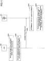
- FIG. 11 is a sequence diagram for illustrating a connection operation according to one embodiment of the present invention.
- the base station 100 receives a connection request from the user equipment 50. Specifically, the base station 100 receives an RRC Connection Request and an RRC Connection Setup Complete.
- the base station 100 selects the management apparatus 200 to accommodate the user equipment 50 based on the received connection request. Specifically, the base station 100 performs an NNSF to determine the management apparatus 201 to accommodate the user equipment 50 based on the received connection request.
- the base station 100 transmits the connection request for the user equipment 50 to the selected management apparatus 201. Specifically, the base station 100 transmits an Initial UE Message including eNB UE S1AP ID to the management apparatus 201.
- the management apparatus 201 determines the type of the user equipment 50. For example, if the user equipment 50 is connecting by an Initial Attach, the management apparatus 201 may obtain subscription information of the user equipment 50 from an upper station (IPSCP/HSS or the like) and determine the type (UE Usage Type) of the user equipment 50. Alternatively, if the user equipment 50 is connecting by a Service Request or a TAU, the management apparatus 201 may obtain the type (UE Usage Type) of the user equipment 50 from the management apparatus 202 that has accommodated the user equipment 50 in a previous session.
- IPSCP/HSS an upper station
- the management apparatus 201 performs a reroute operation to accommodate the user equipment 50 in another management apparatus 203 corresponding to the type of the user equipment 50.
- the management apparatus 201 transmits a reroute message, including NAS information to connect to the management apparatus 203, to the base station 100 without providing the identifier of the user equipment 50 by the management apparatus 201 (MME UE S1AP ID).
- MME UE S1AP ID the management apparatus 201 transmits NAS MESSAGE REROUTE to the base station 100 to indicate a reroute from the management apparatus 201 to the M2M dedicated management apparatus 203 without providing the identifier of the user equipment 50 by the management apparatus 201 (MME UE S1AP ID).
- the base station 100 can transmit an Initial UE Message, including the identifier of the user equipment 50 already configured by the base station (eNB UE S1AP ID), to the management apparatus 203 and establish an S1 Connection to the management apparatus 203 by the reused identifier (eNB UE S1AP ID).
- eNB UE S1AP ID the identifier of the user equipment 50 already configured by the base station
- the block diagrams for use in the above description of embodiments show blocks for functional units. These functional blocks (components) are implemented in any combination of hardware and/or software items. Also, the implementations of the respective functional blocks are not particularly limited. In other words, the respective functional blocks may be implemented in a physically and/or logically coupled single device or in multiple devices where two or more physically and/or logically separated devices are connected directly and/or indirectly (for example, in wired and/or wireless manners).
- the user equipment 50, the base station 100 and the management apparatus 200 may function as a computer processing the radio communication method according to the present invention.
- FIG. 12 is a block diagram for illustrating a hardware arrangement of the user equipment 50, the base station 100 and the management apparatus 200 according to one embodiment of the present invention.
- the user equipment 50, the base station 100 and the management apparatus 200 as stated above may each be physically arranged as a computer device including a processor 1001, a memory 1002, a storage 1003, a communication device 1004, an input device 1005, an output device 1006, a bus 1007 or the like.
- apparatus can be interchangeably read as a circuit, a device, a unit or the like.
- the hardware arrangement of the user equipment 50, the base station 100 and the management apparatus 200 may each be arranged to include one or more of the illustrated devices or without including a part of the devices.
- Respective functions in the user equipment 50, the basle station 100 and the management apparatus 200 are implemented by loading a predetermined software item (program) into hardware items such as the processor 1001 and the memory 1002 to cause the processor 1001 to execute operations, perform communication with the communication device 1004 and control read and/or write operations on data from/in the memory 1002 and the storage 1003.
- a predetermined software item program
- hardware items such as the processor 1001 and the memory 1002 to cause the processor 1001 to execute operations, perform communication with the communication device 1004 and control read and/or write operations on data from/in the memory 1002 and the storage 1003.
- the processor 1001 runs an operating system to control the whole computer, for example.
- the processor 1001 may be arranged with a central processing unit (CPU) including an interface with a peripheral device, a control device, a calculation device, a register and the like.
- CPU central processing unit
- the above-stated components may be implemented in the processor 1001.
- the processor 1001 loads programs (program codes), software modules and data from the storage 1003 and/or the communication device 104 into the memory 1002 and executes various operations in accordance with them.
- programs programs for causing the computer to perform at least a part of operations as described in the above embodiments are used.
- operations by the components in the user equipment 50, the base station 100 and the management apparatus 200 may be implemented with control programs stored in the memory 1002 and executed by the processor 1001, and other functional blocks may be similarly implemented. It has been described that the above-stated various operations are performed by the single processor 1001, but they may be performed with two or more processors 1001 simultaneously or sequentially.
- the processor 1001 may be implemented with one or more chips. Note that the programs may be transmitted from a network via an electric communication line.
- the memory 1002 is a computer-readable storage medium and may be arranged with at least one of a ROM (Read Only Memory), an EPROM (Erasable Programmable ROM), an EEPROM (Electrically Erasable Programmable ROM), a RAM (Random Access Memory) or the like, for example.
- the memory 1002 may be referred to as a register, a cache, a main memory (main storage device) or the like.
- the memory 1002 can store programs (program codes), software modules or the like that can be executed to implement the radio communication method according to one embodiment of the present invention.
- the storage 1003 is a computer-readable storage medium and may be arranged with at least one of an optical disk such as a CD-ROM (Compact Disc ROM), a hard disk drive, a flexible disk, a magnetic optical disk (for example, a compact disk, a digital versatile disk, a Blu-ray (registered trademark) disk), a smart card, a flash memory (for example, a card, a stick, a key drive), a floppy (registered trademark), a magnetic strip or the like.
- the storage 1003 may be referred to as an auxiliary storage device.
- the above-stated storage medium may be a database or a server including the memory 1002 and/or the storage 1003 or any other appropriate medium.
- the communication device 1004 is a hardware item (transceiver device) for communication over computers via a wired and/or wireless network and may be also referred to as a network device, a network controller, a network card, a communication module or the like.
- a network device for communication over computers via a wired and/or wireless network
- a network controller for communication over computers via a wired and/or wireless network
- a network card for example, the above-stated components may be implemented in the communication device 1004.
- the input device 1005 is an input device for receiving external inputs (for example, a keyboard, a mouse, a microphone, a switch, a button, a sensor or the like).
- the output device 1006 is an output device for providing external outputs (for example, a display, a speaker, a LED ramp or the like). Note that the input device 1005 and the output device 1006 may be integrally arranged (for example, a touch panel).
- the respective devices such as the processor 1001 and the memory 1002 are connected with each other via the bus 1007 for communicating information.
- the bus 1007 may be arranged with a single bus or different buses for different devices.
- the user equipment 50, the base station 100 and the management apparatus 200 may be arranged to include a hardware item such as a macro processor, a digital signal processor (DSP), an ASIC (Application Specific Integrated Circuit), a PLD (Programmable Logic Device), a FPGA (Field Programmable Gate Array) or the like, and a part or all of the functional blocks may be implemented in the hardware item.
- a hardware item such as a macro processor, a digital signal processor (DSP), an ASIC (Application Specific Integrated Circuit), a PLD (Programmable Logic Device), a FPGA (Field Programmable Gate Array) or the like, and a part or all of the functional blocks may be implemented in the hardware item.
- the processor 1001 may be implemented with at least one of these hardware items.
- information may be transmitted in physical layer signaling (for example, DCI (Downlink Control Information) and UCI (Uplink Control Information)), upper layer signaling (for example, RRC (radio Resource Control) signaling, MAC (medium Access Control) signaling, broadcast information (MIB (master Information Block) and SIB (System Information Block)) or any other signal or combinations thereof.
- RRC radio Resource Control
- MAC medium Access Control
- MIB master Information Block
- SIB System Information Block
- the RRC signaling may be referred to as an RRC message and may be an RRC Connection Setup message, an RRC Connection Reconfiguration message or the like.
- LTE Long Term Evolution
- LTE-A Long Term Evolution-Advanced
- SUPER 3G IMT-Advanced
- 4G 5G
- FRA Full Radio Access
- W-CDMA registered trademark
- GSM registered trademark
- CDMA 2000 UMB (Ultra Mobile Broadband)
- IEEE 802.11 Wi-Fi
- IEEE 802.16 WiMAX
- IEEE 802.20 UWB (Ultra-WideBand)
- Bluetooth registered trademark
- Procedures, sequences, flowcharts or the like of the respective embodiments/implementations as described in the present specification may be permutable, as long as there is not inconsistency.
- various steps are presented in an exemplary order, and the present invention is not limited to the presented certain order.
- Certain operations performed by the base station 100 as described in the present specification may be performed by its upper node in some cases.
- various operations performed to communicate with terminals may be apparently performed by the base stations and/or network nodes other than the base stations (for example, a MME or an S-SW can be assumed, but the network nodes are not limited to them).
- a MME or an S-SW can be assumed, but the network nodes are not limited to them.
- the single network node other than the base stations is used in the above example, combinations of multiple other network nodes (for example, a MME and an S-GW) may be used.
- Information and others may be output from an upper layer (or a lower layer) to a lower layer (or an upper layer). They may be input and output via multiple network nodes.
- Incoming and outgoing information and others may be stored in a certain location (for example, a memory) and/or managed in a management table.
- the incoming and outgoing information and others may be overwritten, updated or added.
- the outgoing information and others may be deleted.
- the incoming information and others may be transmitted to other device.
- Determination may be made with a one-bit value (0 or 1), a Boolean value (true or false) or numerical comparison (for example, comparison with a predetermined value).
- indication of predetermined information is not limited to explicit manners and may be performed implicitly (for example, the predetermined information is not indicated).
- Software should be broadly interpreted to mean an instruction, an instruction set, a code, a code segment, a program code, a program, a subprogram, a software module, an application, a software application, a software package, a routine, a subroutine, an object, an executable file, an execution thread, a procedure, a function or the like regardless of the software being referred to as software, a firmware, a middleware, a microcode, a hardware descriptive language or other names.
- the software, the instruction or the like may be transmitted and received via a transmission medium.
- a transmission medium For example, if the software is transmitted from a website, a server or other remote sources by using wired techniques such as a coaxial cable, an optical fiber cable, a twist pair and a digital subscriber line (DSL) and/or wireless techniques such as infrared, radio frequency and microwave, these wired techniques and/or wireless techniques are included within definition of a transmission medium.
- wired techniques such as a coaxial cable, an optical fiber cable, a twist pair and a digital subscriber line (DSL) and/or wireless techniques such as infrared, radio frequency and microwave
- Information, signals or the like as described in the present specification may be represented with use of any of various different techniques.
- data, an instruction, a command, information, a signal, a bit, a symbol, a chip and so on referred to throughout the above description may be represented with a voltage, a current, an electromagnetic wave, a magnetic field, a magnetic particle, an optical field, a photon or any combination thereof.
- a channel and/or a symbol may be a signal.
- the signal may be a message.
- a component carrier CC may be referred to as a carrier frequency, a cell or the like.
- information, a parameter and so on as described in the present specification may be represented with an absolute value, a relative value from a predetermined value or other corresponding information.
- a radio resource may be specified with an index.
- a base station can accommodate one or more (for example, three) cells (also referred to as sectors). If the base station accommodates multiple cells, the whole coverage area of the base station can be segmented into multiple smaller areas, and the respective smaller areas can provide communication services with a base station subsystem (for example, indoor small base station RRH: Remote Radio Head).
- a base station subsystem for example, indoor small base station RRH: Remote Radio Head.
- the terminology "cell” or “sector” indicates a part or whole of the coverage area of the base station providing communication services in the coverage and/or the base station subsystem.
- the terminologies "base station”, “eNB”, “cell” and “sector” can be interchangeably used in the present specification.
- the base station may be referred to as terminologies such as a fixed station, a NodeB, an eNodeB (eNB), an access point, a femtocell and a small cell.
- a mobile station may be referred to by those skilled in the art as a subscriber station, a mobile unit, a subscriber unit, a wireless unit, a remote unit, a mobile device, a wireless device, a wireless communication device, a remote device, a mobile subscriber station, an access terminal, a mobile terminal, a wireless terminal, a remote terminal, a handset, a user agent, a mobile client, a client or any other appropriate terminologies.
- the "determining” may include various operations.
- the “determining” may include calculating, computing, processing, deriving, investigating, looking up (for example, looking up a table, a database or other data structures) and ascertaining, for example.
- the "determining” may include receiving (for example, receiving information), transmitting (for example, transmitting information), inputting, outputting and accessing (for example, accessing data in a memory).
- the "determining” may include resolving, selecting, choosing, establishing, comparing or the like. In other words, the "determining” may include any operation.
- the terminologies "connected”, “coupled” or all variations thereof mean direct or indirect connection or coupling between two or more elements and can include existence of one or more intermediate elements between two mutually “connected” or “coupled” elements.
- the coupling or connection between elements may be physical, logical or in combinations thereof. If they are used in the present specification, it can be considered that two elements are mutually “connected” or “coupled” with use of one or more electric wires, cables and/or print electric connections and as several non-limiting and non-comprehensive examples, with use of electromagnetic energy such as electromagnetic energy having a wavelength of a radio frequency domain, a microwave domain and an optical (both visible and invisible) domain.
- a reference signal can be omitted as a RS (Reference Signal) and may be referred to as a pilot depending on applied standards.
- RS Reference Signal
- any reference to elements with use of terminologies such as “first”, “second” and so on as used in the present specification does not limit the amount or order of these elements in general. These terminologies can be used in the present specification as convenient manners for distinguishing between two or more elements. Accordingly, the reference to the first and second elements does not mean that only the two elements are used there or the first element has to precede the second element in any fashion.
- a radio frame may be arranged with one or more frames in a time domain.
- one or more frames each may be referred to as a subframe.
- the subframe may be further arranged with one or more slots in the time domain.
- the slot may be further arranged with one or more symbols (OFDM symbols, SC-FDMA symbols and so on) in the time domain.
- Any of the radio frame, the subframe, the slot and the symbol represents a time unit for transmitting signals.
- the radio frame, the subframe, the slot and the symbol may be referred to in other corresponding manners.
- a base station performs scheduling to assign radio resources (frequency bandwidths, transmission power and so on available in the mobile station) to mobile stations.
- the minimum time unit for scheduling may be referred to as a TTI (Transmission Time Interval).
- TTI Transmission Time Interval
- a resource block may be a resource assignment unit in the time domain and the frequency domain and may include one or more successive subcarriers in the frequency domain.
- the resource block may include one or more symbols and have one slot, one subframe or one TTI in length.
- the single TTI and subframe each may be arranged with one or more resource blocks.
- radio frame is merely exemplary, and the number of subframes in the radio frame, the number of slots in the subframe, the number of symbols and resource blocks in the slot and the number of subcarriers in the resource block can be changed in any manner.
Landscapes
- Engineering & Computer Science (AREA)
- Computer Networks & Wireless Communication (AREA)
- Signal Processing (AREA)
- Databases & Information Systems (AREA)
- Computer Security & Cryptography (AREA)
- Mobile Radio Communication Systems (AREA)
Abstract
Description
- The present invention relates to a radio communication system.
- It is envisaged that not only mobile phones and smartphones but also various things may be connected to the Internet in the future. Various techniques for implementing the IoT (Internet of Things) are presently discussed. As one of the techniques, DECOR (Dedicated Core Network) has been discussed in Rel-13 of LTE (Long Term Evolution) as a control technique for separating general users such as mobile phones and smartphones from M2M (Machine-to-Machine) users such as smart meters and sensors and accommodating respective user equipments in different core networks (CNs) corresponding to device types and/or subscription types.
- As illustrated in
FIG. 1 , in addition to an existing EPC (Evolved Packet Core), an M2M dedicated EPC for M2M users is provided in the DECOR. Upon visiting a base station (evolved NodeB: eNB), user equipment (UE) transmits an Attach/TAU (Tracking Area Update) to the base station. Upon receiving the Attach/TAU, the base station transmits the Attach/TAU to an existing EPC serving as a default CN. Upon receiving the Attach/TAU, the existing EPC transmits an Updated Location Request (ULR) to an IPSCP (IP Service Control Point) or an HSS (Home Subscriber Server). The IPSCP or the HSS returns an Update Location Answer (ULA) to indicate subscription information (user information, an APN (Access Point Name), an UE type (UE Usage Type) or the like) on the user equipment to the existing EPC. The existing EPC determines the UE type from the received subscription information and redirects the Attach/TAU corresponding to the determined UE type. Specifically, the existing EPC determines whether the user equipment is the general user or the M2M user based on the UE type. If the UE type is the general user, the existing EPC accommodates the user equipment. On the other hand, if the UE type is the M2M user, the existing EPC redirects the Attach/TAU to an M2M dedicated EPC (dedicated CN). In this manner, according to the DECOR, even if lower prioritized M2M terminals are congested, the M2M users are accommodated by the M2M dedicated EPC, which can avoid influence on the general users. Besides, since there are cases where a network function to accommodate the M2M terminals differs from a network function to accommodate the general users, according to the DECOR, the M2M terminals can be allocated to resources for the dedicated core network, and there are some merits where functions and/or resources to be possessed by the dedicated core network can be efficiently introduced. - In the DECOR, a base station redirects a NAS (Non Access Stratum) message to an M2M dedicated EPC based on Dedicated MMEGI (Mobility Management Entity Group Identity). Here, in a conventional CN selection control function where the DECOR is not applied (NAS Node Selection Function: NNSF), upon receiving a connection request from user equipment, the base station selects an MME (Mobility Management Entity) for the user equipment. Specifically, if the user equipment is connecting by an Initial Attach, the base station uses a GUMMEI (Globally Unique MME Identity) or a Selected PLMN (Public Land Mobile Network) included in an RRC Connection Setup Complete to select one MME from MMEs in the relevant network (PLMN) randomly. On the other hand, if the user equipment is connecting by a Service Request (restoration from a Preservation state) or a TAU, the base station uses a S-TMSI (SAE Temporary Mobile Subscriber Identity) included in an RRC Connection Request to restore the connection to the relevant MME.
- Specifically, in the case where the user equipment attempts the connection by the Service Request or the TAU, as illustrated in
FIG. 2 , the user equipment first transmits an RRC Connection Request including the S-TMSI to the base station. After returning an RRC Connection Setup, the base station receives an RRC Connection Setup Complete including a Registered MME and a Selected PLMN from the user equipment. Upon receiving the RRC Connection Setup Complete, the base station performs the NNSF and transmits an Initial UE Message toMME# 1 corresponding to the Registered MME. Upon receiving the Initial UE Message, theMME# 1 exchanges an Initial Context Setup Request or an Initial Context Setup Response with the base station, and an S1 Connection for the relevant UE will be established between the base station and the MME#L. -
- Non-patent document 1: 3GPP TS 36.300 V13.0.0 (2015-06)
- Non-patent document 2: 3GPP TS 36.413 V13.0.0 (2015-06)
- Non-patent document 3: 3GPP TS 23.401 V13.3.0 (2015-06)
- Considering the above-stated NNSF, it can be considered that the DECOR applied NNSF may follow a procedure as illustrated in
FIG. 3 . Specifically, similar to the procedure inFIG. 2 , upon receiving an RRC Connection Setup Complete from the user equipment, the base station transmits an Initial UE Message including a NAS PDU to theMME# 1. Upon receiving the Initial UE Message, theMME# 1 transmits an Identification Request toMME# 2 interacting with the user equipment in a previous session. Upon receiving the Identification Request, theMME# 2 returns an Identification Response including an UE Usage Type of the user equipment. Assuming that the UE type is the M2M user, theMME# 1 transmits a DL (Downlink) NAS TRANSPORT including a NAS PDU (Packet Data Unit) and an MMEGI to the base station to redirect the user equipment to the M2M MME. Upon receiving the DL NAS TRANSPORT, the base station transmits an Initial UE Message to the M2M MME corresponding to the MMEGI and exchanges the Initial Context Setup Request and the Initial Context Setup Response with the M2M MME. As a result, the S1 Connection for the relevant UE is established between the base station and the M2M MME. - Here, in the case where the procedure for rerouting the NAS message incoming from the
MME# 1 to the M2M MME is performed in the DL NAS TRANSPORT, there are some problems where an S1AP ID for uniquely identifying the user equipment in an S1 interface (I/F) is unnecessarily assigned. Specifically, as illustrated inFIG. 4 , the MME UE S1AP ID is essentially set in the DL NAS TRANSPORT, and accordingly the MME will set the MME UE S1AP IE. As a result, at this timing, a pair of the eNB UE S1AP ID (eNB UES1AP ID# 1 in the illustrated example) for identifying the user equipment at the base station and the MME UE S1AP ID (MME UE S1AP ID#A in the illustrated example) is established. On the other hand, although the base station transmits an Initial UE Message to the reroute destination M2M MME at the next timing, the base station must reassign another eNB UE S1AP ID (eNB UES1AP ID# 2 in the illustrated example) at that timing. In other words, the pair of the eNB UES1AP ID# 1 and the MME UE S1AP ID#A is deleted without substantial use, and an S1 Connection will be established with the pair of the eNB UES1AP ID# 2 and the MME UE S1AP ID#X. - In light of the above-stated problem, an object of the present invention is to provide techniques for establishing connection to the reroute destination MME without setting any unnecessary identifier.
- In order to achieve the above object, one aspect of the present invention relates to a base station, comprising: a connection request processing unit configured to, upon receiving a connection request from user equipment, perform a connection operation on the user equipment; and a core network connection unit configured to, upon receiving a reroute message to indicate a reroute from a first management apparatus to a second management apparatus, transmit NAS (Non Access Stratum) information in the reroute message to the second management apparatus without establishing an S1 connection for the first management apparatus and the user equipment.
- Another aspect of the present invention relates to a management apparatus, comprising: a user type determination unit configured to, upon receiving a connection request of user equipment from a base station, determine a type of the user equipment; and a reroute processing unit configured to perform a reroute operation to accommodate the user equipment in another management apparatus corresponding to the type of the user equipment, wherein the reroute processing unit transmits a reroute message to the base station without providing an identifier of the user equipment by the management apparatus, the reroute message including NAS (Non Access Stratum) information to connect to the other management apparatus.
- A still further aspect of the present invention relates to a connection method for connecting user equipment to a core network, the method comprising: receiving, by a base station, a connection request from user equipment; selecting, by the base station, a management apparatus to accommodate the user equipment based on the received connection request; transmitting, by the base station, the connection request for the user equipment to the selected management apparatus; determining, by the selected management apparatus, a type of the user equipment; and performing, by the selected management apparatus, a reroute operation to accommodate the user equipment in another management apparatus corresponding to the type of the user equipment, wherein the performing the reroute operation includes transmitting a reroute message to the base station without providing an identifier of the user equipment by the selected management apparatus, the reroute message including NAS (Non Access Stratum) information to connect to the other management apparatus.
- According to the present invention, it is possible to establish connection to the reroute destination MME without setting any unnecessary identifier.
-
-
FIG. 1 is a schematic diagram for illustrating the DECOR; -
FIG. 2 is a sequence diagram for illustrating an NNSF procedure; -
FIG. 3 is a sequence diagram for illustrating a DECOR applied NNSF procedure; -
FIG. 4 is a detailed sequence diagram for illustrating the DECOR applied NNSF procedure; -
FIG. 5 is a schematic diagram for illustrating a radio communication system according to one embodiment of the present invention; -
FIG. 6 is a sequence diagram for illustrating the DECOR applied NNSF procedure according to one embodiment of the present invention; -
FIG. 7 is a sequence diagram for illustrating a procedure for rerouting an NAS PDU according to one embodiment of the present invention; -
FIG. 8 is a diagram for illustrating an information element NAS MESSAGE REROUTE according to one embodiment of the present invention; -
FIG. 9 is a block diagram for illustrating an arrangement of a base station according to one embodiment of the present invention; -
FIG. 10 is a block diagram for illustrating an arrangement of a management apparatus according to one embodiment of the present invention; -
FIG. 11 is a sequence diagram for illustrating a connection operation according to one embodiment of the present invention; and -
FIG. 12 is a block diagram for illustrating a hardware arrangement of the user equipment, the base station and the management apparatus according to one embodiment of the present invention. - Embodiments of the present invention are described below with reference to the drawings.
- In embodiments below, a base station (eNB) and a management apparatus (MME) to connect user equipment to a core network in the DECOR are disclosed. Summarizing embodiments as stated below, when the management apparatus to accommodate the user equipment is rerouted in the DECOR, the reroute source management apparatus indicates the reroute to the base station without providing an identifier (MME UE S1AP ID) for identifying the UE. As a result, in contrast to the conventional DL NAS TRANSPORT procedure, the base station does not have to reconfigure an identifier (eNB UE S1AP ID) corresponding to the UE identifier (MME UE S1AP ID) assigned by the reroute source management apparatus and can reuse the already configured identifier (eNB UE S1AP ID) for the reroute source management apparatus to establish connection (S1 Connection) to the reroute destination management apparatus.
- A radio communication system according to one embodiment of the present invention is described with reference to
FIG. 5. FIG. 5 is a schematic diagram for illustrating a radio communication system according to one embodiment of the present invention. - As illustrated in
FIG. 5 , theradio communication system 10 hasuser equipment 50, a base station (eNB) 100 and a management apparatus (EPC) 200. For example, theradio communication system 10 may be an LTE system or an LTE-Advanced system. In the illustrated embodiment, only thesingle base station 100 is illustrated, but a large number ofbase stations 100 are disposed to cover a service area of theradio communication system 10. - The
user equipment 50 communicates with thebase station 100 via a cell served by thebase station 100. Typically, theuser equipment 50 may be any appropriate information processing apparatus having a radio communication function such as a smartphone, a cellular phone, a tablet, a mobile router, a wearable terminal, a smart meter, a sensor, a photo frame, a car navigation system and a gaming device. In this embodiment, theuser equipment 50 is classified into a general user such as a cellular phone and a smartphone and an M2M user such as a smart meter and a sensor. In general, communication by the general user is prioritized over communication by the M2M user. - The
base station 100 wirelessly connects to theuser equipment 50 to transmit a downlink (DL) packet received from various network devices via themanagement apparatus 200 and an uplink (UL) packet received from theuser equipment 50 to the network devices. In this embodiment, upon receiving a connection request from theuser equipment 50, thebase station 100 performs a core node selection function (NNSF) to select themanagement apparatus 200 to accommodate theuser equipment 50 based on the received connection request and transmits an Initial UE Message including the eNB UE S1AP ID to the selectedmanagement apparatus 200. - The
base station 100 is typically arranged with hardware resources such as an antenna for transmitting and receiving radio signals to/from theuser equipment 50, a communication interface (X2 interface or the like) for communicating withadjacent base stations 100, a communication interface (S1 interface or the like) for communicating with themanagement apparatus 200 and a processor and/or a circuit for processing signals transmitted and received to/from theuser equipment 50 and themanagement apparatus 200. Functions and operations of thebase station 100 as stated below may be implemented by the processor processing or executing data and/or programs stored in a memory device. However, thebase station 100 is not limited to the above-stated hardware arrangement and may have any other appropriate hardware arrangement. - The
management apparatus 200 composes a core network including an EPC and an MME. In this embodiment, thebase station 100 and themanagement apparatus 200 support the DECOR. Specifically, themanagement apparatus 200 determines the type of theuser equipment 50 in response to a connection request such as an Attach/TAU and a Service Request of theuser equipment 50 received from thebase station 100. Depending on the determination, the general user is accommodated in thedefault management apparatus 200, and the M2M user is accommodated in the M2Mdedicated management apparatus 200. Themanagement apparatus 200 is typically implemented with a server or the like, and functions and operations of themanagement apparatus 200 as stated below may be implemented by the processor processing or executing data and/or programs stored in the memory device. However, themanagement apparatus 200 is not limited to the above-stated hardware arrangement and may have any other appropriate hardware arrangement. - Next, some operations to connect the user equipment to the core network in the DECOR according to one embodiment of the present invention are described with reference to
FIGS. 6-8 .FIG. 6 is a sequence diagram for illustrating the DECOR applied NNSF procedure according to one embodiment of the present invention. - As illustrated in
FIG. 6 , when theuser equipment 50 transmits an RRC Connection Request to thebase station 100 at step S101, a connection operation is performed between theuser equipment 50 and thebase station 100 via exchanges of an RRC Connection Setup and an RRC Connection Setup Complete. - At step S102, the
base station 100 performs an NNSF based on an S-TMSI included in the RRC Connection Request or a Registered MME and a Selected PLMN included in the RRC Connection Setup Complete to determine a management apparatus 201 (New MME#1) to accommodate theuser equipment 50. - At step S103, the
base station 100 transmits an Initial UE Message including an eNB UE S1AP ID to themanagement apparatus 201. - At step S104, the
management apparatus 201 identifies theuser equipment 50 based on the received Initial UE Message. In the illustrated example, themanagement apparatus 201 identifies that theuser equipment 50 has been accommodated in a management apparatus 202 (Old MME#2) in a previous session and transmits an Identification Request to themanagement apparatus 202. Upon receiving the Identification Request, themanagement apparatus 202 returns an Identification Response including an UE Usage Type indicative of a type of theuser equipment 50 to themanagement apparatus 201. - At step S105, the
management apparatus 201 identifies the type of theuser equipment 50 to apply the DECOR and determines themanagement apparatus 200 to accommodate theuser equipment 50 corresponding to the identified type. In the illustrated example, it is determined that theuser equipment 50 is an M2M user, and themanagement apparatus 201 selects a management apparatus 203 (Second MME) as themanagement apparatus 200 to accommodate theuser equipment 50 and transmits an NAS Rerouting Command to thebase station 100 to redirect the connection request to themanagement apparatus 203. In the conventional procedure illustrated inFIG. 4 , DL NAS TRANSPORT is performed, and the eNB UE S1AP ID is reconfigured corresponding to the MME UE S1AP ID provided in the DL NAS TRANSPORT. In this embodiment, however, themanagement apparatus 201 uses the eNB UE S1AP ID included in the Initial UE Message received at step S104 to transmit the NAS Rerouting Command to thebase station 100 without providing the MME UE S1AP ID. As a result, thebase station 100 does not have to configure any new eNB UE S1AP ID corresponding to the MME UE S1AP ID. - Specifically, as illustrated in
FIG. 7 , themanagement apparatus 201 transmits a reroute message (NAS MESSAGE REROUTE) to thebase station 100 to indicate a reroute from themanagement apparatus 201 to themanagement apparatus 203 including the NAS information to connect to themanagement apparatus 203 without providing an identifier (MME S1AP ID) of theuser equipment 50. - At step S106, upon receiving the reroute message, the
base station 100 transmits the Initial UE Message including the already configured eNB UE S1AP ID to themanagement apparatus 203 without configuring any new eNB UE S1AP ID to exchange an Initial Context Setup Request and an Initial Context Setup Response. - At step S107, an S1 Connection is established between the
base station 100 and themanagement apparatus 203, and the eNB UE S1AP ID configured at step S104 will be associated with the MME UE S1AP ID provided by themanagement apparatus 203. - As stated above, the NAS MESSAGE REROUTE is transmitted by the
management apparatus 201 and is used to indicate to thebase station 100 that the NAS information has to be rerouted to themanagement apparatus 203. The NAS MESSAGE REROUTE may essentially include information elements (IEs) of Message Type, eNB UE S1AP ID and MME GI NAS-PDU as illustrated inFIG. 8 , but the MME GI for identifying themanagement apparatus 201 may be configured to be ignored. In other examples, in addition to the essential information elements (IEs) Message Type, eNB UE S1AP ID, MME GI and NAS-PDU as illustrated inFIG. 8 , the NAS MESSAGE REROUTE may include an MME UE S1AP ID as an arbitrary information element (IE), but the MME UE S1AP ID and the MME GI for identifying themanagement apparatus 201 may be analogously configured to be ignored. - Next, the base station according to one embodiment of the present invention is described with reference to
FIG. 9. FIG. 9 is a block diagram for illustrating an arrangement of the base station according to one embodiment of the present invention. - As illustrated in
FIG. 9 , thebase station 100 has a connectionrequest processing unit 110 and a corenetwork connection unit 120. - Upon receiving a connection request from the
user equipment 50, the connectionrequest processing unit 110 performs a connection operation on theuser equipment 50. Specifically, the connectionrequest processing unit 110 exchanges an RRC Connection Request, an RRC Connection Setup and an RRC Connection Setup Complete with theuser equipment 50. - Upon receiving a reroute message to indicate a reroute from the
management apparatus 201 to themanagement apparatus 203, the corenetwork connection unit 120 transmits NAS information in the reroute message to themanagement apparatus 203 without establishing an S1 connection for themanagement apparatus 201 and theuser equipment 50. Specifically, since an identifier of theuser equipment 50 in the S1 Connection by the management apparatus 201 (MME UE S1AP ID) is not provided in the NAS MESSAGE REROUTE received from themanagement apparatus 201 or is indicated to be ignored, the corenetwork connection unit 120 does not have to configure the eNB UE S1AP ID corresponding to the MME UE S1AP ID. Accordingly, the corenetwork connection unit 120 can reuse the eNB UE S1AP ID configured at transmitting the Initial UE Message to themanagement apparatus 201 to transmit the Initial UE Message including the eNB UE S1AP ID to themanagement apparatus 203. - In one embodiment, the
management apparatus 201 may have a default MME in the DECOR, and themanagement apparatus 203 may have an M2M dedicated MME in the DECOR. The reroute message may instruct thebase station 100 to reroute theuser equipment 50 from the default MME to the M2M dedicated MME. In contrast to the conventional DL NAS TRANSPORT, the identifier of theuser equipment 50 assigned by the management apparatus 201 (MME UE S1AP ID) is not provided or is configured to be ignored in the reroute message. Accordingly, the corenetwork connection unit 120 does not have to reconfigure the identifier of theuser equipment 50 by the base station 100 (eNB UE S1AP ID) corresponding to the identifier of theuser equipment 50 by themanagement apparatus 201. - In one embodiment, the core
network connection unit 120 may establish the S1 connection for themanagement apparatus 203 and theuser equipment 50 in association of an identifier of theuser equipment 50 by thebase station 100 transmitting to themanagement apparatus 201 with an identifier of theuser equipment 50 by themanagement apparatus 203. As stated above, the corenetwork connection unit 120 may not reconfigure the identifier of theuser equipment 50 by the base station 100 (eNB UE S1AP ID) corresponding to the identifier of theuser equipment 50 by the management apparatus 201 (MME UE S1AP ID). Accordingly, the corenetwork connection unit 120 can reuse the identifier assigned by the base station 100 (eNB UE S1AP ID) at transmitting an Initial UE Message to themanagement apparatus 201 to transmit the Initial UE Message including the identifier to the reroutedestination management apparatus 203 and establish the S1 Connection with a pair of the identifier and the identifier of theuser equipment 50 assigned by the management apparatus 203 (MME UE S1AP ID). - In one embodiment, the core
network connection unit 120 may perform a core node selection function to select themanagement apparatus 201 as a management apparatus to accommodate theuser equipment 50 based on the connection request received from theuser equipment 50. For example, if theuser equipment 50 is attempting connection by an Initial Attach, the corenetwork connection unit 120 may use a GUMMEI or a Selected PLMN in an RRC Connection Setup Complete to select themanagement apparatus 201. Alternatively, if theuser equipment 50 is attempting connection by a Service Request or a TAU, the corenetwork connection unit 120 may use an S-TMSI in an RRC Connection Request to select themanagement apparatus 201. - Next, the management apparatus according to one embodiment of the present invention is described with reference to
FIG. 10. FIG. 10 is a block diagram for illustrating an arrangement of the management apparatus according to one embodiment of the present invention. - As illustrated in
FIG. 10 , themanagement apparatus 200 serves as the reroutesource management apparatus 201 in the above-stated example and has a usertype determination unit 210 and a rerouteprocessing unit 220. - Upon receiving a connection request of the
user equipment 50 from thebase station 100, the usertype determination unit 210 determines a type of theuser equipment 50. Specifically, if theuser equipment 50 is connecting by an Initial Attach, the usertype determination unit 210 may obtain subscription information of theuser equipment 50 from an upper station (IPSCP/HSS or the like) and determine the type (UE Usage Type) of theuser equipment 50. Alternatively, if theuser equipment 50 is connecting by a Service Request or a TAU, the usertype determination unit 210 may obtain the type (UE Usage Type) of theuser equipment 50 from themanagement apparatus 202 that has accommodated theuser equipment 50 in a previous session. - The reroute
processing unit 220 performs a reroute operation to accommodate theuser equipment 50 in anothermanagement apparatus 203 corresponding to the type of theuser equipment 50 and transmits a reroute message, including NAS information to connect to themanagement apparatus 203, to thebase station 100 without providing an identifier of theuser equipment 50 by themanagement apparatus 201. Specifically, if theuser equipment 50 is an M2M user, the rerouteprocessing unit 220 transmits NAS MESSAGE REROUTE to thebase station 100 to indicate a reroute from thedefault management apparatus 201 to the M2Mdedicated management apparatus 203 without providing an identifier of theuser equipment 50 by the management apparatus 201 (MME UE S1AP ID). In contrast to the conventional DL NAS TRANSPORT, the identifier of theuser equipment 50 assigned by the management apparatus 201 (MME UE S1AP ID) is not provided or is configured to be ignored in the NAS MESSAGE REROUTE according to the present invention. Accordingly, in response to reception of the NAS MESSAGE REROUTE, thebase station 100 does not have to reconfigure the identifier of theuser equipment 50 by the base station 100 (eNB UE S1AP ID) corresponding to the identifier of theuser equipment 50 by the management apparatus 201 (MME UE S1AP ID) and can reuse the identifier already configured by the base station (eNB UE S1AP ID) for themanagement apparatus 203. - In one embodiment, the
management apparatus 201 may have a default MME in the DECOR, and theother management apparatus 203 may have an M2M dedicated MME in the DECOR. The reroute message may instruct thebase station 100 to reroute theuser equipment 50 from the default MME to the M2M dedicated MME. In contrast to the conventional DL NAS TRANSPORT, the identifier of theuser equipment 50 by the management apparatus 201 (MME UE S1AP ID) is not provided or is configured to be ignored in the reroute message. Accordingly, thebase station 100 does not have to reconfigure the identifier of theuser equipment 50 assigned by the base station 100 (eNB UE S1AP ID) corresponding to the identifier of theuser equipment 50 assigned by themanagement apparatus 201. - Next, some connection operations to connect the
user equipment 50 to a core network according to one embodiment of the present invention are described with reference toFIG. 11. FIG. 11 is a sequence diagram for illustrating a connection operation according to one embodiment of the present invention. - At step S201, the
base station 100 receives a connection request from theuser equipment 50. Specifically, thebase station 100 receives an RRC Connection Request and an RRC Connection Setup Complete. - At step S202, the
base station 100 selects themanagement apparatus 200 to accommodate theuser equipment 50 based on the received connection request. Specifically, thebase station 100 performs an NNSF to determine themanagement apparatus 201 to accommodate theuser equipment 50 based on the received connection request. - At step S203, the
base station 100 transmits the connection request for theuser equipment 50 to the selectedmanagement apparatus 201. Specifically, thebase station 100 transmits an Initial UE Message including eNB UE S1AP ID to themanagement apparatus 201. - At step S204, the
management apparatus 201 determines the type of theuser equipment 50. For example, if theuser equipment 50 is connecting by an Initial Attach, themanagement apparatus 201 may obtain subscription information of theuser equipment 50 from an upper station (IPSCP/HSS or the like) and determine the type (UE Usage Type) of theuser equipment 50. Alternatively, if theuser equipment 50 is connecting by a Service Request or a TAU, themanagement apparatus 201 may obtain the type (UE Usage Type) of theuser equipment 50 from themanagement apparatus 202 that has accommodated theuser equipment 50 in a previous session. - At step S205, the
management apparatus 201 performs a reroute operation to accommodate theuser equipment 50 in anothermanagement apparatus 203 corresponding to the type of theuser equipment 50. Here, themanagement apparatus 201 transmits a reroute message, including NAS information to connect to themanagement apparatus 203, to thebase station 100 without providing the identifier of theuser equipment 50 by the management apparatus 201 (MME UE S1AP ID). Specifically, if theuser equipment 50 is an M2M user, themanagement apparatus 201 transmits NAS MESSAGE REROUTE to thebase station 100 to indicate a reroute from themanagement apparatus 201 to the M2Mdedicated management apparatus 203 without providing the identifier of theuser equipment 50 by the management apparatus 201 (MME UE S1AP ID). Upon receiving the NAS MESSAGE REROUTE, thebase station 100 can transmit an Initial UE Message, including the identifier of theuser equipment 50 already configured by the base station (eNB UE S1AP ID), to themanagement apparatus 203 and establish an S1 Connection to themanagement apparatus 203 by the reused identifier (eNB UE S1AP ID). - Here, the block diagrams for use in the above description of embodiments show blocks for functional units. These functional blocks (components) are implemented in any combination of hardware and/or software items. Also, the implementations of the respective functional blocks are not particularly limited. In other words, the respective functional blocks may be implemented in a physically and/or logically coupled single device or in multiple devices where two or more physically and/or logically separated devices are connected directly and/or indirectly (for example, in wired and/or wireless manners).
- For example, the
user equipment 50, thebase station 100 and themanagement apparatus 200 according to one embodiment of the present invention may function as a computer processing the radio communication method according to the present invention.FIG. 12 is a block diagram for illustrating a hardware arrangement of theuser equipment 50, thebase station 100 and themanagement apparatus 200 according to one embodiment of the present invention. Theuser equipment 50, thebase station 100 and themanagement apparatus 200 as stated above may each be physically arranged as a computer device including aprocessor 1001, amemory 1002, astorage 1003, acommunication device 1004, aninput device 1005, anoutput device 1006, abus 1007 or the like. - Note that the language "apparatus"' can be interchangeably read as a circuit, a device, a unit or the like. The hardware arrangement of the
user equipment 50, thebase station 100 and themanagement apparatus 200 may each be arranged to include one or more of the illustrated devices or without including a part of the devices. - Respective functions in the
user equipment 50, thebasle station 100 and themanagement apparatus 200 are implemented by loading a predetermined software item (program) into hardware items such as theprocessor 1001 and thememory 1002 to cause theprocessor 1001 to execute operations, perform communication with thecommunication device 1004 and control read and/or write operations on data from/in thememory 1002 and thestorage 1003. - The
processor 1001 runs an operating system to control the whole computer, for example. Theprocessor 1001 may be arranged with a central processing unit (CPU) including an interface with a peripheral device, a control device, a calculation device, a register and the like. For example, the above-stated components may be implemented in theprocessor 1001. - Also, the
processor 1001 loads programs (program codes), software modules and data from thestorage 1003 and/or the communication device 104 into thememory 1002 and executes various operations in accordance with them. As the programs, programs for causing the computer to perform at least a part of operations as described in the above embodiments are used. For example, operations by the components in theuser equipment 50, thebase station 100 and themanagement apparatus 200 may be implemented with control programs stored in thememory 1002 and executed by theprocessor 1001, and other functional blocks may be similarly implemented. It has been described that the above-stated various operations are performed by thesingle processor 1001, but they may be performed with two ormore processors 1001 simultaneously or sequentially. Theprocessor 1001 may be implemented with one or more chips. Note that the programs may be transmitted from a network via an electric communication line. - The
memory 1002 is a computer-readable storage medium and may be arranged with at least one of a ROM (Read Only Memory), an EPROM (Erasable Programmable ROM), an EEPROM (Electrically Erasable Programmable ROM), a RAM (Random Access Memory) or the like, for example. Thememory 1002 may be referred to as a register, a cache, a main memory (main storage device) or the like. Thememory 1002 can store programs (program codes), software modules or the like that can be executed to implement the radio communication method according to one embodiment of the present invention. - The
storage 1003 is a computer-readable storage medium and may be arranged with at least one of an optical disk such as a CD-ROM (Compact Disc ROM), a hard disk drive, a flexible disk, a magnetic optical disk (for example, a compact disk, a digital versatile disk, a Blu-ray (registered trademark) disk), a smart card, a flash memory (for example, a card, a stick, a key drive), a floppy (registered trademark), a magnetic strip or the like. Thestorage 1003 may be referred to as an auxiliary storage device. The above-stated storage medium may be a database or a server including thememory 1002 and/or thestorage 1003 or any other appropriate medium. - The
communication device 1004 is a hardware item (transceiver device) for communication over computers via a wired and/or wireless network and may be also referred to as a network device, a network controller, a network card, a communication module or the like. For example, the above-stated components may be implemented in thecommunication device 1004. - The
input device 1005 is an input device for receiving external inputs (for example, a keyboard, a mouse, a microphone, a switch, a button, a sensor or the like). Theoutput device 1006 is an output device for providing external outputs (for example, a display, a speaker, a LED ramp or the like). Note that theinput device 1005 and theoutput device 1006 may be integrally arranged (for example, a touch panel). - Also, the respective devices such as the
processor 1001 and thememory 1002 are connected with each other via thebus 1007 for communicating information. Thebus 1007 may be arranged with a single bus or different buses for different devices. - Also, the
user equipment 50, thebase station 100 and themanagement apparatus 200 may be arranged to include a hardware item such as a macro processor, a digital signal processor (DSP), an ASIC (Application Specific Integrated Circuit), a PLD (Programmable Logic Device), a FPGA (Field Programmable Gate Array) or the like, and a part or all of the functional blocks may be implemented in the hardware item. For example, theprocessor 1001 may be implemented with at least one of these hardware items. - Transmission of information is not limited to the embodiments/implementations as described in the present specification and may be made in any other manner. For example, information may be transmitted in physical layer signaling (for example, DCI (Downlink Control Information) and UCI (Uplink Control Information)), upper layer signaling (for example, RRC (radio Resource Control) signaling, MAC (medium Access Control) signaling, broadcast information (MIB (master Information Block) and SIB (System Information Block)) or any other signal or combinations thereof. Also, the RRC signaling may be referred to as an RRC message and may be an RRC Connection Setup message, an RRC Connection Reconfiguration message or the like.
- The respective embodiments/implementations as described in the present specification may be applied to systems using LTE (Long Term Evolution), LTE-A (LTE-Advanced), SUPER 3G, IMT-Advanced, 4G, 5G, FRA (Future Radio Access), W-CDMA (registered trademark), GSM (registered trademark), CDMA 2000, UMB (Ultra Mobile Broadband), IEEE 802.11 (Wi-Fi), IEEE 802.16 (WiMAX), IEEE 802.20, UWB (Ultra-WideBand), Bluetooth (registered trademark) or any other appropriate system or next-generation systems enhanced based on them.
- Procedures, sequences, flowcharts or the like of the respective embodiments/implementations as described in the present specification may be permutable, as long as there is not inconsistency. For example, for methods as described in the present specification, various steps are presented in an exemplary order, and the present invention is not limited to the presented certain order.
- Certain operations performed by the
base station 100 as described in the present specification may be performed by its upper node in some cases. In a network including one or more network nodes having base stations, various operations performed to communicate with terminals may be apparently performed by the base stations and/or network nodes other than the base stations (for example, a MME or an S-SW can be assumed, but the network nodes are not limited to them). Although it has been described that the single network node other than the base stations is used in the above example, combinations of multiple other network nodes (for example, a MME and an S-GW) may be used. - Information and others may be output from an upper layer (or a lower layer) to a lower layer (or an upper layer). They may be input and output via multiple network nodes.
- Incoming and outgoing information and others may be stored in a certain location (for example, a memory) and/or managed in a management table. The incoming and outgoing information and others may be overwritten, updated or added. The outgoing information and others may be deleted. The incoming information and others may be transmitted to other device.
- Determination may be made with a one-bit value (0 or 1), a Boolean value (true or false) or numerical comparison (for example, comparison with a predetermined value).
- The embodiments/implementations as described in the present specification may be used singularly or in combinations or switched in connection with execution. Also, indication of predetermined information (for example, indication "it is X") is not limited to explicit manners and may be performed implicitly (for example, the predetermined information is not indicated).
- Although the present invention has been described in detail, it is apparent to those skilled in the art that the present invention is not limited to the embodiments as described in the present specification. The present invention can be implemented as modifications and variations without departing from the sprit and scope of the present invention as defined in claims. Thus, the description in the present specification is intended for exemplary description and does not mean any restriction to the present invention.
- Software should be broadly interpreted to mean an instruction, an instruction set, a code, a code segment, a program code, a program, a subprogram, a software module, an application, a software application, a software package, a routine, a subroutine, an object, an executable file, an execution thread, a procedure, a function or the like regardless of the software being referred to as software, a firmware, a middleware, a microcode, a hardware descriptive language or other names.
- Also, the software, the instruction or the like may be transmitted and received via a transmission medium. For example, if the software is transmitted from a website, a server or other remote sources by using wired techniques such as a coaxial cable, an optical fiber cable, a twist pair and a digital subscriber line (DSL) and/or wireless techniques such as infrared, radio frequency and microwave, these wired techniques and/or wireless techniques are included within definition of a transmission medium.
- Information, signals or the like as described in the present specification may be represented with use of any of various different techniques. For example, data, an instruction, a command, information, a signal, a bit, a symbol, a chip and so on referred to throughout the above description may be represented with a voltage, a current, an electromagnetic wave, a magnetic field, a magnetic particle, an optical field, a photon or any combination thereof.
- Note that terminologies described in the present specification and/or terminologies required to understand the present specification may be replaced with terminologies having the same or similar meanings. For example, a channel and/or a symbol may be a signal. Also, the signal may be a message. Also, a component carrier (CC) may be referred to as a carrier frequency, a cell or the like.
- The terminologies "system" and "network" for use in the present specification are interchangeably used.
- Also, information, a parameter and so on as described in the present specification may be represented with an absolute value, a relative value from a predetermined value or other corresponding information. For example, a radio resource may be specified with an index.
- Names as used for the above-stated parameters are not restrictive from any standpoint. Furthermore, there are some cases where formulae and so on using these parameters may be different from ones as explicitly disclosed in the present specification. Various channels (for example, a PUCCH, a PDCCH or the like) and information elements (for example, a TPC or the like) can be identified with any preferred names, and the various names assigned to these various channels and information elements are not restrictive from any standpoint.
- A base station can accommodate one or more (for example, three) cells (also referred to as sectors). If the base station accommodates multiple cells, the whole coverage area of the base station can be segmented into multiple smaller areas, and the respective smaller areas can provide communication services with a base station subsystem (for example, indoor small base station RRH: Remote Radio Head). The terminology "cell" or "sector" indicates a part or whole of the coverage area of the base station providing communication services in the coverage and/or the base station subsystem. Furthermore, the terminologies "base station", "eNB", "cell" and "sector" can be interchangeably used in the present specification. The base station may be referred to as terminologies such as a fixed station, a NodeB, an eNodeB (eNB), an access point, a femtocell and a small cell.
- A mobile station may be referred to by those skilled in the art as a subscriber station, a mobile unit, a subscriber unit, a wireless unit, a remote unit, a mobile device, a wireless device, a wireless communication device, a remote device, a mobile subscriber station, an access terminal, a mobile terminal, a wireless terminal, a remote terminal, a handset, a user agent, a mobile client, a client or any other appropriate terminologies.
- There are some cases where terminologies "determining" as used in the present specification may include various operations. The "determining" may include calculating, computing, processing, deriving, investigating, looking up (for example, looking up a table, a database or other data structures) and ascertaining, for example. Also, the "determining" may include receiving (for example, receiving information), transmitting (for example, transmitting information), inputting, outputting and accessing (for example, accessing data in a memory). Also, the "determining" may include resolving, selecting, choosing, establishing, comparing or the like. In other words, the "determining" may include any operation.
- The terminologies "connected", "coupled" or all variations thereof mean direct or indirect connection or coupling between two or more elements and can include existence of one or more intermediate elements between two mutually "connected" or "coupled" elements. The coupling or connection between elements may be physical, logical or in combinations thereof. If they are used in the present specification, it can be considered that two elements are mutually "connected" or "coupled" with use of one or more electric wires, cables and/or print electric connections and as several non-limiting and non-comprehensive examples, with use of electromagnetic energy such as electromagnetic energy having a wavelength of a radio frequency domain, a microwave domain and an optical (both visible and invisible) domain.
- A reference signal can be omitted as a RS (Reference Signal) and may be referred to as a pilot depending on applied standards.
- The recitation "based on" as used in the present specification does not mean "only based on", unless specifically stated otherwise. In other words, the recitation "based on" means both "only based on" and "at least based on".
- Any reference to elements with use of terminologies such as "first", "second" and so on as used in the present specification does not limit the amount or order of these elements in general. These terminologies can be used in the present specification as convenient manners for distinguishing between two or more elements. Accordingly, the reference to the first and second elements does not mean that only the two elements are used there or the first element has to precede the second element in any fashion.
- The terminology "means" in an arrangement of each apparatus as stated above may be replaced with "unit", "circuit", "device" or the like.
- As long as the terminologies "including", "comprising" and variations thereof are used in the present specification or claims, these terminologies are intended to be inclusive similar to the terminology "comprising". Furthermore, the terminology "or" as used in the present specification or claims is intended not to be an exclusive OR.
- A radio frame may be arranged with one or more frames in a time domain. In the time domain, one or more frames each may be referred to as a subframe. The subframe may be further arranged with one or more slots in the time domain. The slot may be further arranged with one or more symbols (OFDM symbols, SC-FDMA symbols and so on) in the time domain. Any of the radio frame, the subframe, the slot and the symbol represents a time unit for transmitting signals. The radio frame, the subframe, the slot and the symbol may be referred to in other corresponding manners. For example, in LTE systems, a base station performs scheduling to assign radio resources (frequency bandwidths, transmission power and so on available in the mobile station) to mobile stations. The minimum time unit for scheduling may be referred to as a TTI (Transmission Time Interval). For example, one subframe, multiple successive subframes or one slot may be referred to as the TTI. A resource block (RB) may be a resource assignment unit in the time domain and the frequency domain and may include one or more successive subcarriers in the frequency domain. Also, in the time domain, the resource block may include one or more symbols and have one slot, one subframe or one TTI in length. The single TTI and subframe each may be arranged with one or more resource blocks. The above-stated arrangement of radio frame is merely exemplary, and the number of subframes in the radio frame, the number of slots in the subframe, the number of symbols and resource blocks in the slot and the number of subcarriers in the resource block can be changed in any manner.
- Although the embodiments of the present invention have been described in detail, the present invention is not limited to the above-stated specific embodiments, and various modifications and variations can be made within the spirit of the present invention as recited in claims.
- This international patent application is based on and claims priority of Japanese Priority Application No.
2015-159996 filed on August 13, 2015 -
- 10:
- radio communication system
- 50:
- user equipment
- 100:
- base station
- 200:
- management apparatus
Claims (8)
- A base station, comprising:a connection request processing unit configured to, upon receiving a connection request from user equipment, perform a connection operation on the user equipment; anda core network connection unit configured to, upon receiving a reroute message to indicate a reroute from a first management apparatus to a second management apparatus, transmit NAS (Non Access Stratum) information in the reroute message to the second management apparatus without establishing an S1 connection for the first management apparatus and the user equipment.
- The base station as claimed in claim 1, wherein the first management apparatus has a default MME (Mobility Management Entity) in DECOR, and the second management apparatus has an M2M (Machine-to-Machine) dedicated MME in the DECOR, and the reroute message instructs the base station to reroute the user equipment from the default MME to the M2M dedicated MME.
- The base station as claimed in claim 1 or 2, wherein the core network connection unit establishes the S1 connection for the second management apparatus and the user equipment in association of an identifier of the user equipment by the base station transmitting to the first management apparatus with an identifier of the user equipment by the second management apparatus.
- The base station as claimed in any one of claims 1 to 3, wherein the core network connection unit performs a core node selection function to select the first management apparatus as a management apparatus to accommodate the user equipment based on the connection request received from the user equipment.
- A management apparatus, comprising:a user type determination unit configured to, upon receiving a connection request of user equipment from a base station, determine a type of the user equipment; anda reroute processing unit configured to perform a reroute operation to accommodate the user equipment in another management apparatus corresponding to the type of the user equipment,wherein the reroute processing unit transmits a reroute message to the base station without providing an identifier of the user equipment by the management apparatus, the reroute message including NAS (Non Access Stratum) information to connect to the other management apparatus.
- The management apparatus as claimed in claim 5, wherein the management apparatus has a default MME (Mobility Management Entity) in DECOR, and the other management apparatus has an M2M (Machine-to-Machine) dedicated MME in the DECOR, and the reroute message instructs the base station to reroute the user equipment from the default MME to the M2M dedicated MME.
- The management apparatus as claimed in claim 5 or 6, wherein the identifier of the user equipment by the management apparatus is not configured in the reroute message.
- A connection method for connecting user equipment to a core network, the method comprising:receiving, by a base station, a connection request from user equipment;selecting, by the base station, a management apparatus to accommodate the user equipment based on the received connection request;transmitting, by the base station, the connection request for the user equipment to the selected management apparatus;determining, by the selected management apparatus, a type of the user equipment; andperforming, by the selected management apparatus, a reroute operation to accommodate the user equipment in another management apparatus corresponding to the type of the user equipment,wherein the performing the reroute operation includes transmitting a reroute message to the base station without providing an identifier of the user equipment by the selected management apparatus, the reroute message including NAS (Non Access Stratum) information to connect to the other management apparatus.
Applications Claiming Priority (2)
| Application Number | Priority Date | Filing Date | Title |
|---|---|---|---|
| JP2015159996A JP6177845B2 (en) | 2015-08-13 | 2015-08-13 | Base station, management apparatus and connection method |
| PCT/JP2016/073651 WO2017026531A1 (en) | 2015-08-13 | 2016-08-10 | Base station, management device, and connection method |
Publications (3)
| Publication Number | Publication Date |
|---|---|
| EP3310124A1 true EP3310124A1 (en) | 2018-04-18 |
| EP3310124A4 EP3310124A4 (en) | 2018-08-15 |
| EP3310124B1 EP3310124B1 (en) | 2021-12-15 |
Family
ID=57984065
Family Applications (1)
| Application Number | Title | Priority Date | Filing Date |
|---|---|---|---|
| EP16835228.4A Active EP3310124B1 (en) | 2015-08-13 | 2016-08-10 | Base station, management device, and connection method |
Country Status (5)
| Country | Link |
|---|---|
| US (1) | US10674564B2 (en) |
| EP (1) | EP3310124B1 (en) |
| JP (1) | JP6177845B2 (en) |
| CN (1) | CN107926079A (en) |
| WO (1) | WO2017026531A1 (en) |
Families Citing this family (2)
| Publication number | Priority date | Publication date | Assignee | Title |
|---|---|---|---|---|
| EP4030796B1 (en) * | 2015-11-19 | 2026-04-15 | SK Telecom Co., Ltd. | Method and apparatus for selecting core network in mobile communication system |
| US11516081B2 (en) * | 2018-06-21 | 2022-11-29 | Ntt Docomo, Inc. | Communication device and communication method |
Family Cites Families (11)
| Publication number | Priority date | Publication date | Assignee | Title |
|---|---|---|---|---|
| CN101291536B (en) * | 2008-05-30 | 2011-12-28 | 中兴通讯股份有限公司 | Switching method for load rebalance of mobility management entity |
| KR101609580B1 (en) * | 2010-02-10 | 2016-04-07 | 삼성전자주식회사 | Wireless communication system and method for establishing connection between user equipment and mobility management entity |
| CN110650505B (en) * | 2013-03-21 | 2022-04-08 | 北京三星通信技术研究有限公司 | A method to support switching |
| UA116025C2 (en) * | 2013-07-04 | 2018-01-25 | Нек Корпорейшн | SYSTEM, METHOD AND DEVICE OF COMMUNICATION |
| WO2015003753A1 (en) * | 2013-07-12 | 2015-01-15 | Nokia Solutions And Networks Oy | Redirection of m2m devices |
| JP2015050759A (en) * | 2013-09-05 | 2015-03-16 | 株式会社日立製作所 | Traffic control method and traffic control apparatus |
| JP6420337B2 (en) * | 2013-11-01 | 2018-11-07 | 華為技術有限公司Huawei Technologies Co.,Ltd. | Network selection method and core network device |
| GB2523773A (en) * | 2014-03-04 | 2015-09-09 | Nec Corp | Communication system |
| CN111510978B (en) * | 2014-05-08 | 2022-06-03 | 交互数字专利控股公司 | Method for redirecting a UE to a dedicated core network node and mobility management entity MME |
| WO2016002692A1 (en) * | 2014-07-01 | 2016-01-07 | シャープ株式会社 | Base station device, first position management device, terminal device, communication control method, and communication system |
| US9674749B2 (en) * | 2014-08-14 | 2017-06-06 | Samsung Electronics Co., Ltd. | Method and apparatus for selecting dedicated core network |
-
2015
- 2015-08-13 JP JP2015159996A patent/JP6177845B2/en active Active
-
2016
- 2016-08-10 CN CN201680046780.0A patent/CN107926079A/en active Pending
- 2016-08-10 WO PCT/JP2016/073651 patent/WO2017026531A1/en not_active Ceased
- 2016-08-10 EP EP16835228.4A patent/EP3310124B1/en active Active
-
2018
- 2018-02-07 US US15/891,217 patent/US10674564B2/en active Active
Also Published As
| Publication number | Publication date |
|---|---|
| CN107926079A (en) | 2018-04-17 |
| HK1252500A1 (en) | 2019-05-31 |
| EP3310124B1 (en) | 2021-12-15 |
| EP3310124A4 (en) | 2018-08-15 |
| JP2017038323A (en) | 2017-02-16 |
| US10674564B2 (en) | 2020-06-02 |
| JP6177845B2 (en) | 2017-08-09 |
| WO2017026531A1 (en) | 2017-02-16 |
| US20180167999A1 (en) | 2018-06-14 |
Similar Documents
| Publication | Publication Date | Title |
|---|---|---|
| US10966116B2 (en) | User equipment | |
| EP3457783A1 (en) | User device and base station | |
| JP6777451B2 (en) | base station | |
| JP2022017475A (en) | Terminal and base station | |
| EP3911022B1 (en) | Network node, and user device | |
| CN110574422B (en) | User equipment, base station and random access method | |
| JP7077227B2 (en) | Core network and base station | |
| CN113261315A (en) | User device, network node and communication system | |
| CN111345093A (en) | Base station device | |
| CN114788358A (en) | Communication method, communication device and communication system | |
| US11277787B2 (en) | Communication control apparatus and communication control method | |
| US20190110308A1 (en) | User equipment | |
| WO2020090069A1 (en) | User device and base station device | |
| WO2020059149A1 (en) | Network node | |
| US10674564B2 (en) | Base station, management apparatus and connection method | |
| JP7049966B2 (en) | Communication control device | |
| WO2021059541A1 (en) | Terminal | |
| JPWO2018034201A1 (en) | Communication method | |
| EP3934345A1 (en) | User device and communication method | |
| JP7563840B2 (en) | Terminal, location registration method, and communication network | |
| US20190166642A1 (en) | Radio communication system | |
| HK1252500B (en) | Base station, management device, and connection method | |
| JP7008641B2 (en) | Gateway selection method and communication system | |
| EP4195780A1 (en) | Terminal, network node, and communication method | |
| EP3579637A1 (en) | Base station and user device |
Legal Events
| Date | Code | Title | Description |
|---|---|---|---|
| STAA | Information on the status of an ep patent application or granted ep patent |
Free format text: STATUS: THE INTERNATIONAL PUBLICATION HAS BEEN MADE |
|
| PUAI | Public reference made under article 153(3) epc to a published international application that has entered the european phase |
Free format text: ORIGINAL CODE: 0009012 |
|
| STAA | Information on the status of an ep patent application or granted ep patent |
Free format text: STATUS: REQUEST FOR EXAMINATION WAS MADE |
|
| 17P | Request for examination filed |
Effective date: 20180112 |
|
| AK | Designated contracting states |
Kind code of ref document: A1 Designated state(s): AL AT BE BG CH CY CZ DE DK EE ES FI FR GB GR HR HU IE IS IT LI LT LU LV MC MK MT NL NO PL PT RO RS SE SI SK SM TR |
|
| AX | Request for extension of the european patent |
Extension state: BA ME |
|
| A4 | Supplementary search report drawn up and despatched |
Effective date: 20180716 |
|
| RIC1 | Information provided on ipc code assigned before grant |
Ipc: H04W 88/18 20090101ALI20180710BHEP Ipc: H04W 92/14 20090101AFI20180710BHEP |
|
| DAV | Request for validation of the european patent (deleted) | ||
| DAX | Request for extension of the european patent (deleted) | ||
| REG | Reference to a national code |
Ref country code: HK Ref legal event code: DE Ref document number: 1252500 Country of ref document: HK |
|
| STAA | Information on the status of an ep patent application or granted ep patent |
Free format text: STATUS: EXAMINATION IS IN PROGRESS |
|
| 17Q | First examination report despatched |
Effective date: 20201113 |
|
| GRAP | Despatch of communication of intention to grant a patent |
Free format text: ORIGINAL CODE: EPIDOSNIGR1 |
|
| STAA | Information on the status of an ep patent application or granted ep patent |
Free format text: STATUS: GRANT OF PATENT IS INTENDED |
|
| INTG | Intention to grant announced |
Effective date: 20210819 |
|
| GRAS | Grant fee paid |
Free format text: ORIGINAL CODE: EPIDOSNIGR3 |
|
| GRAA | (expected) grant |
Free format text: ORIGINAL CODE: 0009210 |
|
| STAA | Information on the status of an ep patent application or granted ep patent |
Free format text: STATUS: THE PATENT HAS BEEN GRANTED |
|
| AK | Designated contracting states |
Kind code of ref document: B1 Designated state(s): AL AT BE BG CH CY CZ DE DK EE ES FI FR GB GR HR HU IE IS IT LI LT LU LV MC MK MT NL NO PL PT RO RS SE SI SK SM TR |
|
| REG | Reference to a national code |
Ref country code: GB Ref legal event code: FG4D Ref country code: CH Ref legal event code: EP |
|
| REG | Reference to a national code |
Ref country code: IE Ref legal event code: FG4D Ref country code: DE Ref legal event code: R096 Ref document number: 602016067460 Country of ref document: DE |
|
| REG | Reference to a national code |
Ref country code: AT Ref legal event code: REF Ref document number: 1456448 Country of ref document: AT Kind code of ref document: T Effective date: 20220115 |
|
| REG | Reference to a national code |
Ref country code: NL Ref legal event code: FP |
|
| REG | Reference to a national code |
Ref country code: LT Ref legal event code: MG9D |
|
| PG25 | Lapsed in a contracting state [announced via postgrant information from national office to epo] |
Ref country code: RS Free format text: LAPSE BECAUSE OF FAILURE TO SUBMIT A TRANSLATION OF THE DESCRIPTION OR TO PAY THE FEE WITHIN THE PRESCRIBED TIME-LIMIT Effective date: 20211215 Ref country code: LT Free format text: LAPSE BECAUSE OF FAILURE TO SUBMIT A TRANSLATION OF THE DESCRIPTION OR TO PAY THE FEE WITHIN THE PRESCRIBED TIME-LIMIT Effective date: 20211215 Ref country code: FI Free format text: LAPSE BECAUSE OF FAILURE TO SUBMIT A TRANSLATION OF THE DESCRIPTION OR TO PAY THE FEE WITHIN THE PRESCRIBED TIME-LIMIT Effective date: 20211215 Ref country code: BG Free format text: LAPSE BECAUSE OF FAILURE TO SUBMIT A TRANSLATION OF THE DESCRIPTION OR TO PAY THE FEE WITHIN THE PRESCRIBED TIME-LIMIT Effective date: 20220315 |
|
| REG | Reference to a national code |
Ref country code: AT Ref legal event code: MK05 Ref document number: 1456448 Country of ref document: AT Kind code of ref document: T Effective date: 20211215 |
|
| PG25 | Lapsed in a contracting state [announced via postgrant information from national office to epo] |
Ref country code: SE Free format text: LAPSE BECAUSE OF FAILURE TO SUBMIT A TRANSLATION OF THE DESCRIPTION OR TO PAY THE FEE WITHIN THE PRESCRIBED TIME-LIMIT Effective date: 20211215 Ref country code: NO Free format text: LAPSE BECAUSE OF FAILURE TO SUBMIT A TRANSLATION OF THE DESCRIPTION OR TO PAY THE FEE WITHIN THE PRESCRIBED TIME-LIMIT Effective date: 20220315 Ref country code: LV Free format text: LAPSE BECAUSE OF FAILURE TO SUBMIT A TRANSLATION OF THE DESCRIPTION OR TO PAY THE FEE WITHIN THE PRESCRIBED TIME-LIMIT Effective date: 20211215 Ref country code: HR Free format text: LAPSE BECAUSE OF FAILURE TO SUBMIT A TRANSLATION OF THE DESCRIPTION OR TO PAY THE FEE WITHIN THE PRESCRIBED TIME-LIMIT Effective date: 20211215 Ref country code: GR Free format text: LAPSE BECAUSE OF FAILURE TO SUBMIT A TRANSLATION OF THE DESCRIPTION OR TO PAY THE FEE WITHIN THE PRESCRIBED TIME-LIMIT Effective date: 20220316 |
|
| PG25 | Lapsed in a contracting state [announced via postgrant information from national office to epo] |
Ref country code: SM Free format text: LAPSE BECAUSE OF FAILURE TO SUBMIT A TRANSLATION OF THE DESCRIPTION OR TO PAY THE FEE WITHIN THE PRESCRIBED TIME-LIMIT Effective date: 20211215 Ref country code: SK Free format text: LAPSE BECAUSE OF FAILURE TO SUBMIT A TRANSLATION OF THE DESCRIPTION OR TO PAY THE FEE WITHIN THE PRESCRIBED TIME-LIMIT Effective date: 20211215 Ref country code: RO Free format text: LAPSE BECAUSE OF FAILURE TO SUBMIT A TRANSLATION OF THE DESCRIPTION OR TO PAY THE FEE WITHIN THE PRESCRIBED TIME-LIMIT Effective date: 20211215 Ref country code: PT Free format text: LAPSE BECAUSE OF FAILURE TO SUBMIT A TRANSLATION OF THE DESCRIPTION OR TO PAY THE FEE WITHIN THE PRESCRIBED TIME-LIMIT Effective date: 20220418 Ref country code: ES Free format text: LAPSE BECAUSE OF FAILURE TO SUBMIT A TRANSLATION OF THE DESCRIPTION OR TO PAY THE FEE WITHIN THE PRESCRIBED TIME-LIMIT Effective date: 20211215 Ref country code: EE Free format text: LAPSE BECAUSE OF FAILURE TO SUBMIT A TRANSLATION OF THE DESCRIPTION OR TO PAY THE FEE WITHIN THE PRESCRIBED TIME-LIMIT Effective date: 20211215 Ref country code: CZ Free format text: LAPSE BECAUSE OF FAILURE TO SUBMIT A TRANSLATION OF THE DESCRIPTION OR TO PAY THE FEE WITHIN THE PRESCRIBED TIME-LIMIT Effective date: 20211215 |
|
| PG25 | Lapsed in a contracting state [announced via postgrant information from national office to epo] |
Ref country code: PL Free format text: LAPSE BECAUSE OF FAILURE TO SUBMIT A TRANSLATION OF THE DESCRIPTION OR TO PAY THE FEE WITHIN THE PRESCRIBED TIME-LIMIT Effective date: 20211215 Ref country code: AT Free format text: LAPSE BECAUSE OF FAILURE TO SUBMIT A TRANSLATION OF THE DESCRIPTION OR TO PAY THE FEE WITHIN THE PRESCRIBED TIME-LIMIT Effective date: 20211215 |
|
| REG | Reference to a national code |
Ref country code: DE Ref legal event code: R097 Ref document number: 602016067460 Country of ref document: DE |
|
| PG25 | Lapsed in a contracting state [announced via postgrant information from national office to epo] |
Ref country code: IS Free format text: LAPSE BECAUSE OF FAILURE TO SUBMIT A TRANSLATION OF THE DESCRIPTION OR TO PAY THE FEE WITHIN THE PRESCRIBED TIME-LIMIT Effective date: 20220415 |
|
| PLBE | No opposition filed within time limit |
Free format text: ORIGINAL CODE: 0009261 |
|
| STAA | Information on the status of an ep patent application or granted ep patent |
Free format text: STATUS: NO OPPOSITION FILED WITHIN TIME LIMIT |
|
| PG25 | Lapsed in a contracting state [announced via postgrant information from national office to epo] |
Ref country code: DK Free format text: LAPSE BECAUSE OF FAILURE TO SUBMIT A TRANSLATION OF THE DESCRIPTION OR TO PAY THE FEE WITHIN THE PRESCRIBED TIME-LIMIT Effective date: 20211215 Ref country code: AL Free format text: LAPSE BECAUSE OF FAILURE TO SUBMIT A TRANSLATION OF THE DESCRIPTION OR TO PAY THE FEE WITHIN THE PRESCRIBED TIME-LIMIT Effective date: 20211215 |
|
| 26N | No opposition filed |
Effective date: 20220916 |
|
| PG25 | Lapsed in a contracting state [announced via postgrant information from national office to epo] |
Ref country code: SI Free format text: LAPSE BECAUSE OF FAILURE TO SUBMIT A TRANSLATION OF THE DESCRIPTION OR TO PAY THE FEE WITHIN THE PRESCRIBED TIME-LIMIT Effective date: 20211215 |
|
| PG25 | Lapsed in a contracting state [announced via postgrant information from national office to epo] |
Ref country code: MC Free format text: LAPSE BECAUSE OF FAILURE TO SUBMIT A TRANSLATION OF THE DESCRIPTION OR TO PAY THE FEE WITHIN THE PRESCRIBED TIME-LIMIT Effective date: 20211215 |
|
| REG | Reference to a national code |
Ref country code: CH Ref legal event code: PL |
|
| PG25 | Lapsed in a contracting state [announced via postgrant information from national office to epo] |
Ref country code: LU Free format text: LAPSE BECAUSE OF NON-PAYMENT OF DUE FEES Effective date: 20220810 Ref country code: LI Free format text: LAPSE BECAUSE OF NON-PAYMENT OF DUE FEES Effective date: 20220831 Ref country code: CH Free format text: LAPSE BECAUSE OF NON-PAYMENT OF DUE FEES Effective date: 20220831 |
|
| PG25 | Lapsed in a contracting state [announced via postgrant information from national office to epo] |
Ref country code: IT Free format text: LAPSE BECAUSE OF FAILURE TO SUBMIT A TRANSLATION OF THE DESCRIPTION OR TO PAY THE FEE WITHIN THE PRESCRIBED TIME-LIMIT Effective date: 20211215 |
|
| P01 | Opt-out of the competence of the unified patent court (upc) registered |
Effective date: 20230509 |
|
| PG25 | Lapsed in a contracting state [announced via postgrant information from national office to epo] |
Ref country code: IE Free format text: LAPSE BECAUSE OF NON-PAYMENT OF DUE FEES Effective date: 20220810 Ref country code: FR Free format text: LAPSE BECAUSE OF NON-PAYMENT OF DUE FEES Effective date: 20220831 |
|
| PG25 | Lapsed in a contracting state [announced via postgrant information from national office to epo] |
Ref country code: HU Free format text: LAPSE BECAUSE OF FAILURE TO SUBMIT A TRANSLATION OF THE DESCRIPTION OR TO PAY THE FEE WITHIN THE PRESCRIBED TIME-LIMIT; INVALID AB INITIO Effective date: 20160810 |
|
| PG25 | Lapsed in a contracting state [announced via postgrant information from national office to epo] |
Ref country code: CY Free format text: LAPSE BECAUSE OF FAILURE TO SUBMIT A TRANSLATION OF THE DESCRIPTION OR TO PAY THE FEE WITHIN THE PRESCRIBED TIME-LIMIT Effective date: 20211215 |
|
| PG25 | Lapsed in a contracting state [announced via postgrant information from national office to epo] |
Ref country code: MK Free format text: LAPSE BECAUSE OF FAILURE TO SUBMIT A TRANSLATION OF THE DESCRIPTION OR TO PAY THE FEE WITHIN THE PRESCRIBED TIME-LIMIT Effective date: 20211215 |
|
| PG25 | Lapsed in a contracting state [announced via postgrant information from national office to epo] |
Ref country code: TR Free format text: LAPSE BECAUSE OF FAILURE TO SUBMIT A TRANSLATION OF THE DESCRIPTION OR TO PAY THE FEE WITHIN THE PRESCRIBED TIME-LIMIT Effective date: 20211215 |
|
| PG25 | Lapsed in a contracting state [announced via postgrant information from national office to epo] |
Ref country code: MT Free format text: LAPSE BECAUSE OF FAILURE TO SUBMIT A TRANSLATION OF THE DESCRIPTION OR TO PAY THE FEE WITHIN THE PRESCRIBED TIME-LIMIT Effective date: 20211215 |
|
| PGFP | Annual fee paid to national office [announced via postgrant information from national office to epo] |
Ref country code: NL Payment date: 20250821 Year of fee payment: 10 |
|
| PGFP | Annual fee paid to national office [announced via postgrant information from national office to epo] |
Ref country code: DE Payment date: 20250820 Year of fee payment: 10 |
|
| PGFP | Annual fee paid to national office [announced via postgrant information from national office to epo] |
Ref country code: BE Payment date: 20250820 Year of fee payment: 10 Ref country code: GB Payment date: 20250821 Year of fee payment: 10 |