EP3310031B1 - Image reading device, document feeder device, and image forming apparatus - Google Patents
Image reading device, document feeder device, and image forming apparatus Download PDFInfo
- Publication number
- EP3310031B1 EP3310031B1 EP17195950.5A EP17195950A EP3310031B1 EP 3310031 B1 EP3310031 B1 EP 3310031B1 EP 17195950 A EP17195950 A EP 17195950A EP 3310031 B1 EP3310031 B1 EP 3310031B1
- Authority
- EP
- European Patent Office
- Prior art keywords
- document feeder
- document
- feeder device
- main unit
- unit
- Prior art date
- Legal status (The legal status is an assumption and is not a legal conclusion. Google has not performed a legal analysis and makes no representation as to the accuracy of the status listed.)
- Active
Links
- 239000011521 glass Substances 0.000 claims description 19
- 238000004891 communication Methods 0.000 claims description 18
- 238000010586 diagram Methods 0.000 description 17
- 230000001105 regulatory effect Effects 0.000 description 9
- 210000000078 claw Anatomy 0.000 description 4
- 238000007599 discharging Methods 0.000 description 4
- 230000005484 gravity Effects 0.000 description 3
- 238000000034 method Methods 0.000 description 3
- 238000012546 transfer Methods 0.000 description 3
- 230000002159 abnormal effect Effects 0.000 description 2
- 230000008878 coupling Effects 0.000 description 2
- 238000010168 coupling process Methods 0.000 description 2
- 238000005859 coupling reaction Methods 0.000 description 2
- 230000002950 deficient Effects 0.000 description 2
- 230000006870 function Effects 0.000 description 2
- 238000009434 installation Methods 0.000 description 2
- 238000011144 upstream manufacturing Methods 0.000 description 2
- 206010047571 Visual impairment Diseases 0.000 description 1
- 230000005540 biological transmission Effects 0.000 description 1
- 230000000295 complement effect Effects 0.000 description 1
- 238000013461 design Methods 0.000 description 1
- 239000000463 material Substances 0.000 description 1
- 229910044991 metal oxide Inorganic materials 0.000 description 1
- 150000004706 metal oxides Chemical class 0.000 description 1
- 238000012545 processing Methods 0.000 description 1
- 239000004065 semiconductor Substances 0.000 description 1
- 210000003462 vein Anatomy 0.000 description 1
Images


Classifications
-
- H—ELECTRICITY
- H04—ELECTRIC COMMUNICATION TECHNIQUE
- H04N—PICTORIAL COMMUNICATION, e.g. TELEVISION
- H04N1/00—Scanning, transmission or reproduction of documents or the like, e.g. facsimile transmission; Details thereof
- H04N1/00519—Constructional details not otherwise provided for, e.g. housings, covers
- H04N1/00557—Connection or assembly of components or elements
-
- H—ELECTRICITY
- H04—ELECTRIC COMMUNICATION TECHNIQUE
- H04N—PICTORIAL COMMUNICATION, e.g. TELEVISION
- H04N1/00—Scanning, transmission or reproduction of documents or the like, e.g. facsimile transmission; Details thereof
- H04N1/00519—Constructional details not otherwise provided for, e.g. housings, covers
- H04N1/00551—Top covers or the like
- H04N1/00554—Latches or hinges therefor
-
- H—ELECTRICITY
- H04—ELECTRIC COMMUNICATION TECHNIQUE
- H04N—PICTORIAL COMMUNICATION, e.g. TELEVISION
- H04N1/00—Scanning, transmission or reproduction of documents or the like, e.g. facsimile transmission; Details thereof
- H04N1/00567—Handling of original or reproduction media, e.g. cutting, separating, stacking
- H04N1/0057—Conveying sheets before or after scanning
- H04N1/00599—Using specific components
-
- H—ELECTRICITY
- H04—ELECTRIC COMMUNICATION TECHNIQUE
- H04N—PICTORIAL COMMUNICATION, e.g. TELEVISION
- H04N1/00—Scanning, transmission or reproduction of documents or the like, e.g. facsimile transmission; Details thereof
- H04N1/00795—Reading arrangements
-
- H—ELECTRICITY
- H04—ELECTRIC COMMUNICATION TECHNIQUE
- H04N—PICTORIAL COMMUNICATION, e.g. TELEVISION
- H04N1/00—Scanning, transmission or reproduction of documents or the like, e.g. facsimile transmission; Details thereof
- H04N1/04—Scanning arrangements, i.e. arrangements for the displacement of active reading or reproducing elements relative to the original or reproducing medium, or vice versa
- H04N1/12—Scanning arrangements, i.e. arrangements for the displacement of active reading or reproducing elements relative to the original or reproducing medium, or vice versa using the sheet-feed movement or the medium-advance or the drum-rotation movement as the slow scanning component, e.g. arrangements for the main-scanning
- H04N1/121—Feeding arrangements
- H04N1/1225—Means for maintaining contact between the sheet and the image sensor, e.g. pressing means
-
- H—ELECTRICITY
- H04—ELECTRIC COMMUNICATION TECHNIQUE
- H04N—PICTORIAL COMMUNICATION, e.g. TELEVISION
- H04N1/00—Scanning, transmission or reproduction of documents or the like, e.g. facsimile transmission; Details thereof
- H04N1/04—Scanning arrangements, i.e. arrangements for the displacement of active reading or reproducing elements relative to the original or reproducing medium, or vice versa
- H04N1/12—Scanning arrangements, i.e. arrangements for the displacement of active reading or reproducing elements relative to the original or reproducing medium, or vice versa using the sheet-feed movement or the medium-advance or the drum-rotation movement as the slow scanning component, e.g. arrangements for the main-scanning
- H04N1/121—Feeding arrangements
- H04N1/1235—Feeding a sheet past a transparent plate; Details thereof
-
- H—ELECTRICITY
- H04—ELECTRIC COMMUNICATION TECHNIQUE
- H04N—PICTORIAL COMMUNICATION, e.g. TELEVISION
- H04N1/00—Scanning, transmission or reproduction of documents or the like, e.g. facsimile transmission; Details thereof
- H04N1/44—Secrecy systems
- H04N1/4406—Restricting access, e.g. according to user identity
- H04N1/4426—Restricting access, e.g. according to user identity involving separate means, e.g. a server, a magnetic card
-
- H—ELECTRICITY
- H04—ELECTRIC COMMUNICATION TECHNIQUE
- H04N—PICTORIAL COMMUNICATION, e.g. TELEVISION
- H04N2201/00—Indexing scheme relating to scanning, transmission or reproduction of documents or the like, and to details thereof
- H04N2201/0077—Types of the still picture apparatus
- H04N2201/0094—Multifunctional device, i.e. a device capable of all of reading, reproducing, copying, facsimile transception, file transception
Description
- The present disclosure relates to an image reading device that reads images on sheets, and to an image forming apparatus having the same.
- There are known image forming apparatuses and the like using electrophotography that ask for personal authentication by IC card to improve security. An authentication device that performs the personal authentication is disposed at a position adjacent to an operation panel provided to the image forming apparatus main unit (
U.S. Patent No. 9089064 2013-30042 -
JP2010 250038 - According to a first aspect of the present invention there is provided a document feeder device as specified in
claims 1 to 7. - According to a second aspect of the present invention there is provided an image reading device as specified in claim 8.
- According to a third aspect of the present invention there is provided an image forming apparatus as specified in
claim 9. - Further features of the present invention will become apparent from the following description of embodiments with reference to the attached drawings.
-
-
Figs. 1A and 1B are diagrams illustrating an image forming apparatus according to a first embodiment, whereFig. 1A is a frontal view andFig. 1B is a perspective view. -
Figs. 2A and 2B are diagrams illustrating an image forming device according to the first embodiment, whereFig. 2A is a frontal view andFig. 2B is a perspective view. -
Figs. 3A and 3B are diagrams regarding the first embodiment, whereFig. 3A is a perspective view illustrating a document feeder that is in an open state as to a reader unit, andFig. 3B is an enlarged view of a hinge. -
Fig. 4 is a cross-sectional view of the document feeder. -
Fig. 5 is a control block diagram of the image forming apparatus. -
Figs. 6A and 6B are diagrams regarding the document feeder, whereFig. 6A is a perspective view of a state where a document pressing plate is removed therefrom, andFig. 6B is an explanatory diagram in a case of attaching a card reader thereto. -
Figs. 7A and 7B are diagrams regarding the document feeder, whereFig. 7A is a perspective view of a state where the document pressing plate is removed therefrom, andFig. 7B is a perspective view of a state where the document pressing plate is attached thereto. -
Figs. 8A and 8B are enlarged configuration diagrams of a card reader main unit and main unit cover member, whereFig. 8A is a view from one direction, andFig. 8B is a view from a different direction. -
Fig. 9 is a diagram illustrating a state where part of outer casing of the document feeder has been removed and a motor exposed. -
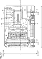
Fig. 10 is a plan view from below the document feeder, in a state where the document pressing plate is removed from the document feeder. -
Fig. 11 is a diagram for describing the configuration of a document discharge tray. - An embodiment will be described in detail with reference to the drawings. An image reading device can make up a standalone configuration such as a flat-bed scanner, and can also be used as an image reading unit in an image forming apparatus such as a photocopier or facsimile device or the like. The image reading device also may have an automatic document feeder (hereinafter referred to as "document feeder"), and be of a configuration where documents are read while being conveyed. Note that the dimensions, materials, shapes, relative layouts, and so forth of components described in the following embodiment do not restrict the present invention in any way, unless specifically stated. Overview of Configuration
-
Fig. 1A is a frontal diagram of animage forming apparatus 1.Fig. 1B is a perspective view of theimage forming apparatus 1. - The
image forming apparatus 1 includes animage reading device 2 and an image forming apparatusmain unit 11. Theimage reading device 2 includes adocument feeder 10 that is a turning unit, areader unit 12 that is a reading unit, adocument stacking tray 15, and adocument discharge tray 16 that is a discharged sheet stacking tray. The image forming apparatusmain unit 11 includes animage forming unit 13, asheet feeding unit 14, and anoperating panel 9. Theoperating panel 9 has animage display unit 9a and akeypad 9b. Theimage forming unit 13 is provided within the image forming apparatusmain unit 11, and forms images by a known electrophotography system. Theimage forming unit 13 has a photosensitive member, an exposing device, a developing device, a transfer device, and a fixing device. The exposing device forms an electrostatic latent image on the photosensitive member based on image information. The developing device develops the electrostatic latent image into a toner image using toner. The transfer device transfers the toner image onto a sheet of recording medium conveyed from thesheet feeding unit 14. The fixing device fixes the toner image on the recording medium onto the recording medium. In a case of copying, the image information is generated by reading an image on a document (sheet) by theimage reading device 2, which is transmitted to theimage forming unit 13. In a case of printing, the image information is transmitted from an external device such as a personal computer (PC) or the like to theimage forming unit 13 as a print job. -
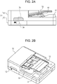
Fig. 2A is an enlarged frontal view of theimage reading device 2 inFig. 1A .Fig. 2B is an enlarged perspective view of theimage reading device 2 inFig. 1B . - The
document stacking tray 15 anddocument discharge tray 16 of theimage reading device 2 are configured to overlap at least partly in the vertical direction. An authentication unit U is provided on the front side of thedocument feeder 10. Acard reader 18, that is acquisition means that acquires authentication information of a user is provided within the authentication unit U. Thecard reader 18 serves to communicate with the user by wireless communication, and more specifically is a non-contact IC card reader. The user causes thecard reader 18 to read the authentication information of the card, by holding the authentication card up to the authentication unit U. - Description will be made regarding a case of performing document flow reading using the
image reading device 2. The user loads a document on thedocument stacking tray 15, and instructs the reading of the document at theoperating panel 9. The document is fed by a sheet feed roller that is omitted from illustration, and an image on the surface of the document is read by areading unit 3a. Note that in a case of reading both faces of the document, an image on the rear face of the document is also read, by areading unit 3b. A compact image sensor (CIS) or complementary metal-oxide semiconductor (CMOS) sensor may be applied for thereading unit 3a. Thedocument discharge tray 16 is provided with aninclined portion 17. Theinclined portion 17 is arranged to protrude more than adjacent portions. A document discharged to thedocument discharge tray 16 rests with just the middle portion thereof in the lateral direction (the direction orthogonal to the conveyance direction of the document) thereof being raised by theinclined portion 17. Accordingly, a gap between thedocument discharge tray 16 and the document is created at the edge portions of the document in the lateral direction, enabling the user to insert his/her hand into this gap, thereby facilitating easy removal of the document by the user. -
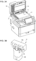
Fig. 3A is a perspective view illustrating a state where thedocument feeder 10 is opened as to thereader unit 12. Thedocument feeder 10 is provided capable of turning as to thereader unit 12 on ahinge 22. Thedocument feeder 10 assumes an open position where areading glass 4 is open, and a closed position where the readingglass 4 is blocked, due to thedocument feeder 10 turning. Thedocument feeder 10 has adocument pressing plate 19. Thedocument pressing plate 19 is configured to press the document upon thereading glass 4 when thedocument feeder 10 is in the closed position. Thereader unit 12 has the readingglass 4.Fig. 3B is an enlarged view of thehinge 22. -
Fig. 3B is an enlarged diagram of thehinge 22. Acoupling portion 22a serves to couple thedocument feeder 10 and hinge 22 to each other. Acoupling portion 22b serves to couple thereader unit 12 and thehinge 22 to each other. Thehinge 22 has arotation shaft 22c, and is structured such that thedocument feeder 10 can turn as to thereader unit 12 on therotation shaft 22c. - A case of loading a document on the
reading glass 4 and performing reading will be described. The user opens thedocument feeder 10 to expose thereading glass 4. The user loads the document on thereading glass 4 with the image facing downwards, and closes thedocument feeder 10. Thedocument pressing plate 19 of thedocument feeder 10 presses the document against the readingglass 4. When the user instructs reading of the document from theoperating panel 9, thereading unit 3a moves and reads the image on the document. -
Fig. 4 is a cross-sectional view of thedocument feeder 10. Apickup roller 30 comes into contact with the uppermost sheet stacked on thedocument stacking tray 15, and feeds this document toward asheet feed roller 31. Thesheet feed roller 31 is provided downstream from thesheet feed roller 31 in the sheet conveyance direction, and conveys documents conveyed from thepickup roller 30 downstream. A separatingroller 32 is in contact with thesheet feed roller 31, and in a case where multiple documents have been conveyed thereto, functions to separate the documents into individual sheets. The separatingroller 32 is rotationally driven via a torque limiter that is omitted from illustration, in a direction of returning documents back toward thedocument stacking tray 15. In a case where two sheets are nipped between thesheet feed roller 31 and the separatingroller 32, the document in contact with the separatingroller 32 is returned in the direction of thedocument stacking tray 15 by the rotation of the separatingroller 32. On the other hand, in a case where only one sheet is nipped between thesheet feed roller 31 and the separatingroller 32, the separatingroller 32 rotates following the rotation of thesheet feed roller 31. The torque value of the aforementioned torque limiter is set so that the driving transmission satisfies such a relationship. - The documents separated into individual sheets by the
sheet feed roller 31 and the separatingroller 32 are conveyed to a position where the images on the documents are read by thereading unit 3a, by conveying roller pairs 33 and 34. After images on the surface of the documents are read by thereading unit 3a, the documents are conveyed by a conveying roller pair 35, and discharged onto thedocument discharge tray 16 by adischarge roller pair 36. -
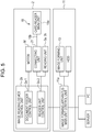
Fig. 5 is a control block diagram of theimage forming apparatus 1. Theimage reading device 2 has an image readingdevice control unit 2a. The image forming apparatusmain unit 11 has an image forming apparatus mainunit control unit 11a is a control circuit board having a central processing unit (CPU), read-only memory (ROM), and random access memory (RAM). The image readingdevice control unit 2a and image forming apparatus mainunit control unit 11a are capable of communication with each other. The image forming apparatus mainunit control unit 11a is capable of communication with a server, PC, or the like, outside of theimage forming apparatus 1. - The image forming apparatus main
unit control unit 11a is electrically connected to theimage forming unit 13 and a hard disk drive (HDD). The image forming apparatus mainunit control unit 11a controls theimage forming unit 13. - The image reading
device control unit 2a has a documentfeeder control unit 2a-1 and areader control unit 2a-2. The documentfeeder control unit 2a-1 andreader control unit 2a-2 each are a control circuit board having a CPU, ROM, and RAM. The documentfeeder control unit 2a-1 is electrically connected to a motor M. Thereader control unit 2a-2 is electrically connected to readingunits unit 21"). The documentfeeder control unit 2a-1 controls the motor M. The motor M provides driving force to thepickup roller 30,sheet feed roller 31, conveying roller pairs 33 through 35, and thedischarge roller pair 36. Note that driving of thepickup roller 30 and so forth may be carried out by a single motor, or by multiple motors. Thereader control unit 2a-2 controls thereading units feeder control unit 2a-1 andreader control unit 2a-2 are electrically connected by a communication cable. This communication cable is guided by a later-describedcable guide 50. - Connecting a
USB cable 18b that is a communication cable for communicating with a card readermain unit 18a (communication means) to the connectingunit 21 enables communication between thecard reader 18 and the image readingdevice control unit 2a. Authentication information of the user that has been read by thecard reader 18 is matched with the user information stored in the HDD of the image forming apparatusmain unit 11, and theimage forming apparatus 1 authenticates the user. Note that the user information may be stored in a server connected to theimage forming apparatus 1 by a network. Attachment Configuration ofCard Reader 18 and Attachment Method - A method of attaching the
card reader 18 to the inside of thedocument discharge tray 16 of a document feedermain unit 10a, and the structure of an attaching portion, will be described with reference toFigs. 6A through 8B . Depending on the location of installation and usage of theimage forming apparatus 1, the authentication device such as thecard reader 18 or the like does not necessarily have to be provided to theimage forming apparatus 1. For example, in a case where the location of installation of theimage forming apparatus 1 is in a public facility and authenticating users is difficult, or in a case where only a few trusted people will be using theimage forming apparatus 1, thecard reader 18 does not necessarily have to be provided. Accordingly, thecard reader 18 seldom is a standard feature, and usually is an additional option. Thus, the configuration is such that thecard reader 18 can be easily attached later. - The work of attachment may be performed by service staff, or by the user. In a case of attaching the
optional card reader 18, thedocument feeder 10 is opened approximately 90 degrees by thehinge 22 that couples thedocument feeder 10 and thereader unit 12. -
Fig. 6A is a perspective view of a state where thedocument pressing plate 19 of thedocument feeder 10 has been removed.Fig. 6B is an explanatory diagram where thecard reader 18 has been attached to the document feedermain unit 10a. - The
document pressing plate 19 is detachably attached to the document feedermain unit 10a bytouch fasteners Multiple touch fasteners 26a are disposed on the document feedermain unit 10a, andtouch fasteners 26b are disposed on thedocument pressing plate 19 at positions corresponding to thetouch fasteners 26a. Removing thedocument pressing plate 19 from the document feedermain unit 10a exposes the interior of thedocument discharge tray 16, as illustrated inFig. 6A . Anattachment part 25, acable cover member 24, and the connectingunit 21 are disposed on the inside of thedocument discharge tray 16. Thecard reader 18 includes the card readermain unit 18a that is a card reading unit, and theUSB cable 18b. A USB terminal of theUSB cable 18b is connected to the connectingunit 21. A control cable (omitted from illustration) for electrically connecting the connectingunit 21 and thereader control unit 2a-2 is guided by thecable guide 50. Thecable guide 50 also guides a control cable for communicating image information read by thereading unit 3b to thereader control unit 2a-2 as well. Although the image readingdevice control unit 2a is configured having the documentfeeder control unit 2a-1 andreader control unit 2a-2 in the present embodiment, this is not restrictive. An image readingdevice control unit 2a that controls the entirety of theimage reading device 2 may be provided to thereader unit 12 alone. - The
attachment part 25 is a portion where the card readermain unit 18a is attached. Screw holes to receive screws 29 (seeFig. 8A ) are provided in theattachment part 25. The card readermain unit 18a is attached to theattachment part 25 via a mainunit cover member 20 that is a supporting container in the present embodiment. The mainunit cover member 20 andcable cover member 24 are detachably mounted within thedocument discharge tray 16. - The procedures of attachment will be described with reference to
Fig. 6B . - The card reader
main unit 18a is held by the main unit cover member 20 (A). The detailed configuration whereby the mainunit cover member 20 holds the card readermain unit 18a will be described later. - The main
unit cover member 20 is fixed within the document feeder 10 (B). Note that the term "within thedocument feeder 10" refers to the space between the document stacking face of thedocument discharge tray 16 and thedocument pressing plate 19. - A USB connector is provided to the end of the
USB cable 18b, and the USB connector is connected to a connecting portion 21b. TheUSB cable 18b is stored in astorage portion 23, and theUSB cable 18b is covered by the cable cover member 24 (C). - The
document pressing plate 19 is attached to the document feedermain unit 10a (D). - Attaching the
card reader 18 in this way enables the image readingdevice control unit 2a to communicate with thecard reader 18. - Now, there are various types of
card readers 18 depending on the manufacturer, and accordingly various lengths of theUSB cable 18b exist, from around 40 cm to around 180 cm. Thedocument feeder 10 is provided so as to be capable of opening/closing as to thereader unit 12. Accordingly, if theUSB cable 18b is stored within thedocument feeder 10 without being appropriately bundled when attaching thecard reader 18, theUSB cable 18b may move within thedocument feeder 10 due to the opening/closing actions of thedocument feeder 10. Consequently, theUSB cable 18b may strike members in the vicinity and generate abnormal sounds. Alternatively, theUSB cable 18b may become crimped by members in the vicinity, such as thedocument pressing plate 19 for example, when attaching thecard reader 18 as described above, which can result in wire breakage. - In the present embodiment, a
storage portion 23 that is storage means for storing theexcess USB cable 18b extending from thecard reader 18 is provided within thedocument feeder 10. Thestorage portion 23 is formed as arectangular rib 23a on the inner side of thedocument discharge tray 16. TheUSB cable 18b is stored in a region on the inner side of therib 23a. -
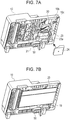
Fig. 7A is a perspective view of a state where theUSB cable 18b is stored in thestorage portion 23, andFig. 7B is a perspective view of a state where thedocument pressing plate 19 of thedocument feeder 10 has been mounted. It can be seen fromFig. 7A that theUSB cable 18b is stored in a bundled state in an interior space surrounded by therib 23a. TheUSB cable 18b is covered by thecable cover member 24 so as to not protrude from therib 23a. Thedocument pressing plate 19 of thedocument feeder 10 is then mounted, as illustrated inFig. 7B . -
Figs. 8A and 8B are enlarged configuration diagrams of the card readermain unit 18a and the mainunit cover member 20. The mainunit cover member 20 includes thetouch fastener 26a,openings 20a,screw attachment portions 20b, aclaw 20c, aweight mounting unit 20d, a securingportion 20d-1, and acable opening 20e. Theopenings 20a are openings through which abelt 27 passes. Thescrew attachment portions 20b are openings through which screws 29 are passed. Thescrews 29 pass through thescrew attachment portions 20b and are fixed in screw holes formed in theattachment part 25. Theclaw 20c engages the document feedermain unit 10a. The mainunit cover member 20 is fixed to the document feedermain unit 10a by thescrews 29 andclaw 20c. Aweight 28 is configured so as to be detachably mounted to theweight mounting unit 20d. Thecable opening 20e extends theUSB cable 18b to the outside of the mainunit cover member 20. The securingportion 20d-1 will be described later. Providing thetouch fastener 26a to the mainunit cover member 20 enables the freedom of layout of thetouch fastener 26b provided on thedocument pressing plate 19 to be improved. - Details of attaching the card reader
main unit 18a will be described. The card readermain unit 18a is fixed to the mainunit cover member 20 using thebelt 27. TheUSB cable 18b is extended to the outside of the mainunit cover member 20 from thecable opening 20e. Theweight 28 is removed from the mainunit cover member 20 by sliding in a direction α. The technical implication of theweight 28 will be described later. Theclaw 20c engages the document feedermain unit 10a. The card readermain unit 18a is fixed to the document feedermain unit 10a by thescrews 29. - According to the present embodiment, the excess portion of the
USB cable 18b is stored in thestorage portion 23. Accordingly, the excess potion of theUSB cable 18b does not protrude from thestorage portion 23 and impede movement of thedocument pressing plate 19. As a result, even if the user opens and closes thedocument feeder 10, the excess portion of theUSB cable 18b is restrained to a certain extent, so a situation where theUSB cable 18b strikes another member and generates abnormal sounds can be suppressed. Further, there is no concern of theUSB cable 18b being pinched between thedocument discharge tray 16 ordocument feeder 10 anddocument pressing plate 19, or other like nearby parts, that might lead to wire breakage. Moreover, storing the excess portion of theUSB cable 18b in thestorage portion 23 facilitates attachment and removal work of thecard reader 18 by service staff or the like. Although a configuration has been described where thestorage portion 23 is covered by thecable cover member 24, thecable cover member 24 does not need to be provided as long as a configuration is made where theUSB cable 18b is generally fixed, being stored in thestorage portion 23. - According to the present embodiment, the
document pressing plate 19 is configured to be detachable from the document feedermain unit 10a, and theattachment part 25 is externally exposed by thedocument pressing plate 19 having been removed. According to this configuration, access within thedocument feeder 10 is facilitated, and attachment/removal of thecard reader 18 is easy. Also, according to the present embodiment, the document feedermain unit 10a has aledge portion 10b protruding so as to cover part of theattachment part 25, as illustrated inFig. 7A . Thus, theledge portion 10b serves to suppress the card readermain unit 18a from falling out from the document feedermain unit 10a. In the present embodiment, the card readermain unit 18a is attached to theattachment part 25 in the document feedermain unit 10a, by first attachment means including the mainunit cover member 20 andbelt 27. Accordingly, the card readermain unit 18a is attached to the mainunit cover member 20 and then attached to the document feedermain unit 10a, so the attachment work is easier than with a configuration of directly attaching the card readermain unit 18a to the document feedermain unit 10a. - Although a configuration has been described in the present embodiment where the
document pressing plate 19 is completely removable from the document feedermain unit 10a, this is not restrictive. An arrangement may be made where only part of thedocument pressing plate 19 is removed from the document feedermain unit 10a. Also, a configuration may be made where part of thedocument pressing plate 19 is coupled with the document feedermain unit 10a and another part of thedocument pressing plate 19 is removable from the document feedermain unit 10a, thereby externally exposing theattachment part 25. - According to the present embodiment, the main
unit cover member 20 has theweight mounting unit 20d, from this theweight 28 is removable. In a case where thecard reader 18 is attached to the document feedermain unit 10a, theweight 28 is removed from the document feedermain unit 10a. In a case of removing thecard reader 18 from the document feedermain unit 10a, theweight 28 is attached to the document feedermain unit 10a. Thus, the weight of thedocument feeder 10 can be kept from greatly changing depending on whether thecard reader 18 is attached or not. - The reason for this will be described. The document placed on the
reading glass 4 is pressed by thedocument pressing plate 19. However, if the weight of thedocument feeder 10 is insufficient, the document may not be appropriately pressed against the readingglass 4, and there may be portions of the document that are not in close contact with the readingglass 4. If there are portions of the document that are not in close contact with the readingglass 4, the reading of the document by thereading unit 3a will be defective. Accordingly, when thecard reader 18 is removed from the document feedermain unit 10a, theweight 28 that has generally the same weight as thecard reader 18 is attached, so that the weight of thedocument feeder 10 does not greatly change depending on whether thecard reader 18 is attached or not. The term "generally the same weight as thecard reader 18" means a weight around that of thecard reader 18 optionally attached to theimage reading device 2, ±20% or so. - The
weight mounting portion 20d of the mainunit cover member 20 has the securingportion 20d-1. To attach theweight 28 to the mainunit cover member 20, theweight 28 is slid in the direction β. Theweight 28 abuts the securingportion 20d-1 and is secured so as not to fall out any further. Once the mainunit cover member 20 is attached to the document feedermain unit 10a, awall 10c of the document feedermain unit 10a is situated at a position facing theweight 28, thereby preventing theweight 28 from falling out. According to this configuration, attaching of theweight 28 to the document feedermain unit 10a is facilitated when the mainunit cover member 20 is removed from the document feedermain unit 10a. On the other hand, theweight 28 can be prevented from falling out from the mainunit cover member 20 when the mainunit cover member 20 is attached to the document feedermain unit 10a. Although the direction of attaching theweight 28 has been described as being the direction β in the present embodiment, this is not restrictive. Theweight 28 may be attached from a direction perpendicular to the direction β. In this case as well, an arrangement may be made where a wall of the document feedermain unit 10a prevents theweight 28 from falling out when the mainunit cover member 20 is attached to the document feedermain unit 10a. - Although a configuration where the
weight mounting portion 20d is provided to the mainunit cover member 20 has been described in the present embodiment, this is not restrictive. A configuration may be made where the mainunit cover member 20 is not used, and theweight 28 is directly attached to the document feedermain unit 10a. -
Fig. 9 is an explanatory diagram illustrating a state where part of outer casing of thedocument feeder 10 has been removed and the motor M exposed.Fig. 10 is a plan view from below thedocument feeder 10, in a state where thedocument pressing plate 19 has been removed from thedocument feeder 10. - In
Figs. 9 and10 , the rotary axis line direction of thehinge 22 is the X direction, and a direction orthogonal to the rotary axis line direction is the Y direction. An imaginary line passing through the center of thedocument feeder 10 in the X direction is denoted by O, and an imaginary line passing through the center of thedocument feeder 10 in the X direction is denoted by P. - In the present embodiment, the motor M is disposed on one side of the imaginary line O in the Y direction, and the
attachment part 25 of the card readermain unit 18a is disposed on the other side of the imaginary line O. Also, the motor M is disposed on one side of the imaginary line P in the X direction, and theattachment part 25 of the card readermain unit 18a is disposed on the other side of the imaginary line P. Thus, the motor M and the card readermain unit 18a that have considerable weight are disposed on opposite sides across the center, thereby preventing the center of gravity of thedocument feeder 10 from greatly deviating from the center of thedocument feeder 10. Thedocument feeder 10 presses the document against the readingglass 4 by thedocument pressing plate 19. If the center of gravity of thedocument feeder 10 greatly deviates from the center, the pressing state of the document may not be uniform, and reading of the image on the document may be defective. The motor M is disposed to the side close to the hinge 22(rear side) in the Y direction, and theattachment part 25 is disposed to the side far from the hinge 22(front side). This makes it difficult for the user to touch the electric system such as the motor M, and easier for the user to perform authentication operations by having theattachment part 25 at the front side. - The
attachment part 25 of the card readermain unit 18a is situated on the same side of the imaginary line P as theoperating panel 9 in the X direction. Having theoperating panel 9 and theattachment part 25 close together in this way reduces the amount of movement of the line of sight of the user in a case where the user is instructed to perform card authentication operations at theoperating panel 9. - A gripping
portion 40 that the user grips to turn thedocument feeder 10 is disposed on the same side of the imaginary line P as the motor M in the X direction. Having the point of effort near the motor M in this way suppresses twisting of thedocument feeder 10 due to the weight of the motor M. - As illustrated in
Fig. 10 , the connectingunit 21 is disposed on the same side of the imaginary line O as the motor M in the Y direction. Situating the connectingunit 21 and the motor M close to each other in this way makes it easier to lay the cable connected to the image readingdevice control unit 2a for driving the motor M, and the cable connected from the connectingunit 21 to the image readingdevice control unit 2a. - The position of the connecting
unit 21 will be described with reference toFig. 10 . The connectingunit 21 andcable guide 50 are situated on the side of the imaginary line O closer to the hinge in the Y direction. The connectingunit 21 andcable guide 50 are also situated on the same side of the imaginary line P. The connectingunit 21 andcable guide 50 are thus situated close to each other. In order to maximally reduce the length of the cable between thedocument feeder 10 and thereader unit 12, thecable guide 50 provided between thedocument feeder 10 andreader unit 12 preferably is provided on the side closer to thehinge 22 in the Y direction. Providing the connectingunit 21 at a position near to thehinge 22 as well enables the cable connected from the connectingunit 21 to thereader unit 12 to be reduced. Note that providing the connectingunit 21 on the side near to thehinge 22 in the Y direction may result in the length of theUSB cable 18b connected from the connectingunit 21 to the card readermain unit 18a to be longer in comparison with a case where the connectingunit 21 is provided on the side far from thehinge 22 in the Y direction (i.e., close to the main unit cover member 20). However, in light of the fact that the user may not necessarily connect thecard reader 18 to thedocument feeder 10, it would be better to maximally reduce the length of the cable connecting thereader unit 12 and the connectingunit 21, thereby eliminating the trouble of routing this cable. - Also, the
cable opening 20e of the mainunit cover member 20 that stores the card readermain unit 18a is situated on the side of an imaginary line Q passing through the center of the mainunit cover member 20 that is closer to the connectingunit 21 in the X direction. Anopening portion 23d of therib 23a of thestorage portion 23 is also situated on the side of an imaginary line R passing through the center of thestorage portion 23 that is closer to the connectingunit 21. Accordingly, that range of routing theUSB cable 18b within thedocument feeder 10 is shorter. -
Fig. 11 is a diagram for describing the configuration of thedocument discharge tray 16. The region of thedocument discharge tray 16 where documents are stacked can be classified into afirst region 16a and asecond region 16b. Note that the region where documents are stacked (thefirst region 16a andsecond region 16b) is defined by the maximum size that theimage reading device 2 can read. The region where documents are stacked (thefirst region 16a andsecond region 16b) does not mean the portion where a document and thedocument discharge tray 16 come into contact, but the part of thedocument discharge tray 16 that is covered by a document. - The
first region 16a is a region where asheet regulating portion 16c is provided on the front side thereof in the Y direction. Thesheet regulating portion 16c is a portion that is higher than abottom face 16d with which documents come into contact. Thesheet regulating portion 16c suppresses documents discharged by thedischarge roller pair 36 from being displaced toward the front side. Thesecond region 16b downstream is a region where no suchsheet regulating portion 16c is provided. Thesecond region 16b is provided on the downstream side of thefirst region 16a in the document discharging direction. - The
bottom face 16d of thefirst region 16a is an inclined face that is higher the farther downstream in the document discharging direction (the same direction as the document conveyance direction). Accordingly, discharged documents are gathered by gravity at the upstream side in the document discharging direction, and are arrayed by the upstream edges thereof coming into contact with acontact wall 16e. - Returning to
Fig. 11 , The authentication unit U (theattachment part 25 where the card readermain unit 18a is provided) preferably is provided in the region where sheets are stacked. However, providing the authentication unit U in thefirst region 16a means providing the authentication unit U at thebottom face 16d or thesheet regulating portion 16c. Providing the authentication unit U on thebottom face 16d is troublesome for the user, since the user has to reach past thesheet regulating portion 16c for authentication. On the other hand, providing the authentication unit U at thesheet regulating portion 16c results in increasing the size of the apparatus, since enough space in the Y direction needs to be secured to install the card readermain unit 18a inside thesheet regulating portion 16c. Accordingly, the authentication unit U is installed at a position at least partly overlapping thesecond region 16b in the present embodiment, making authentication easier for the user. The surface of the authentication unit U is a horizontal plane in the present embodiment, which also makes authentication easier for the user. The upper face of thesheet regulating portion 16c and the face of the authentication unit U are generally flush, presenting the user with a visually simple design. Thesecond region 16b is also provided with theinclined portion 17 that creates a gap between documents discharged onto thedocument discharge tray 16 and the authentication unit U, making authentication easier for the user. - Although description has been made in the above embodiment regarding a device to which a card reader is attached, by way of an example of the
document feeder 10, this is not restrictive. A configuration may be made where a storage portion to store a communication cable is provided within a pressing plate unit that does not have document conveying functions. - Although description has been made in the above embodiment regarding an electrophotographic image forming apparatus, this is not restrictive. The present embodiment may be applied to an ink-jet image forming apparatus that forms images on sheets by discharging ink, instead of an electrophotographic image forming apparatus.
- Although description has been made in the above embodiment regarding a copier having an image forming apparatus main unit as an image reading device, this is not restrictive. The present embodiment may be applied to a standalone image reading device, such as a flatbed scanner.
- Although description has been made in the above embodiment regarding an example of using a card reader as an authentication device that is communication means that wirelessly communicate with the user, this is not restrictive. The present embodiment may be applied to other authentication devices such as fingerprint authentication devices, biometric authentication devices (vein authentication), and so forth. Further, application may be made to communication devices that communicate data of images using Near Field Communication (NFC), other than authentication devices.
- While the present invention has been described with reference to embodiments, it is to be understood that the invention is not limited to the disclosed embodiments. The invention is defined by the feature of the claims.
Claims (9)
- A document feeder device(10) configured to turn by a hinge with respect to a reading unit (2) which includes a reader configured to read an image on a sheet, the document feeder device(10) comprising:a pressing plate (19) arranged to press a sheet on the reading glass (4) against the reading glass (4) when the document feeder device (10) is at a position closing the reading glass (4);a conveying roller (33, 34, 35) arranged to convey a sheet;a motor (M) arranged to rotate the conveying roller (33, 34, 35); andan attachment part (25) to which is attached communication means (18) arranged to receive data from outside of the image reading device (2),wherein, in a direction perpendicular to the turning axis line direction of the hinge (22), the motor (M) is disposed on one side from a center of the document feeder device (10), and the attachment part (25) is disposed on another side from the center of the document feeder device (10) .
- The document feeder device(10) according to Claim 1,
wherein, in the direction perpendicular to the turning axis line direction, the motor (M) is disposed on the side closer to the hinge (22), and the attachment part (25) is disposed on the side farther from the hinge (22). - The document feeder device(10) according to either Claim 1 or claim 2,wherein the document feeder device(10) further include
connecting means (21) to which a communication cable (18b) that communicates with the communication means (18) is connected,and wherein, in the direction perpendicular to the turning axis line direction, the connecting means (21) is disposed on the same side as the motor (M) with respect to the center of the document feeder device(10). - The document feeder device(10) according to any one of Claims 1 through 3,
wherein, in the turning axis line direction, the motor (M) is disposed on one side from the center of the turning means (10), and the communication means (18) is disposed on another side from the center of the turning means (10). - The document feeder device(10) according to any one of Claims 1 through 4,
wherein the document feeder device(10) includes a gripping portion (40) arranged to be gripped by the user to turn the document feeder device(10),
and wherein, in the turning axis line direction, the gripping portion (40) is disposed on the same side as the motor (M) with respect to the center of the turning means (10) . - The document feeder device(10) according to any one of Claims 1 through 5,
wherein, in the turning axis line direction, the communication means (18) is disposed on the same side as an operating panel (9) arranged to accept instructions from the user, with respect to the center of the document feeder device (10). - The document feeder device(10) according to any one of Claims 1 through 6,
wherein the communication means (18) is a card reader main unit (18a). - An image reading device(2) comprising:the document feeder device(10) according to any one of Claims 1 through 7;a reading glass (4); anda reading means(3a) arranged to read the image on the sheet placed on the reading glass (4), through the reading glass(4).
- An image forming apparatus (1) comprising:the image reading device (2) according to Claim 8; andimage forming means (13) arranged to form images based on image information read by the image reading device (2).
Applications Claiming Priority (1)
| Application Number | Priority Date | Filing Date | Title |
|---|---|---|---|
| JP2016200405A JP6821378B2 (en) | 2016-10-11 | 2016-10-11 | Image reader and image forming device |
Publications (2)
| Publication Number | Publication Date |
|---|---|
| EP3310031A1 EP3310031A1 (en) | 2018-04-18 |
| EP3310031B1 true EP3310031B1 (en) | 2020-07-08 |
Family
ID=60201307
Family Applications (1)
| Application Number | Title | Priority Date | Filing Date |
|---|---|---|---|
| EP17195950.5A Active EP3310031B1 (en) | 2016-10-11 | 2017-10-11 | Image reading device, document feeder device, and image forming apparatus |
Country Status (4)
| Country | Link |
|---|---|
| US (1) | US10574844B2 (en) |
| EP (1) | EP3310031B1 (en) |
| JP (1) | JP6821378B2 (en) |
| CN (1) | CN107920181B (en) |
Families Citing this family (8)
| Publication number | Priority date | Publication date | Assignee | Title |
|---|---|---|---|---|
| JP6759044B2 (en) | 2016-10-11 | 2020-09-23 | キヤノン株式会社 | Image reader and image forming device |
| JP6821378B2 (en) * | 2016-10-11 | 2021-01-27 | キヤノン株式会社 | Image reader and image forming device |
| JP6821377B2 (en) | 2016-10-11 | 2021-01-27 | キヤノン株式会社 | Image reader and image forming device |
| JP6838922B2 (en) | 2016-10-11 | 2021-03-03 | キヤノン株式会社 | Image reader and image forming device |
| JP6849378B2 (en) * | 2016-10-11 | 2021-03-24 | キヤノン株式会社 | Image reader and image forming device |
| US10542168B2 (en) | 2016-10-11 | 2020-01-21 | Canon Kabushiki Kaisha | Image reading device and image forming apparatus |
| JP7155838B2 (en) * | 2018-10-03 | 2022-10-19 | ブラザー工業株式会社 | image forming device |
| JP2023080603A (en) * | 2021-11-30 | 2023-06-09 | セイコーエプソン株式会社 | Image reading device and recording device |
Family Cites Families (92)
| Publication number | Priority date | Publication date | Assignee | Title |
|---|---|---|---|---|
| JPS6450069A (en) | 1987-08-21 | 1989-02-27 | Fuji Xerox Co Ltd | Recorder |
| TW225020B (en) | 1992-08-11 | 1994-06-11 | Nisca Corp | |
| JPH0795373A (en) * | 1993-09-22 | 1995-04-07 | Toshiba Corp | Image forming device |
| JPH08294014A (en) | 1995-02-20 | 1996-11-05 | Ricoh Co Ltd | Image processing unit |
| US6252684B1 (en) | 1998-11-13 | 2001-06-26 | Umax Data Systems Inc. | Automatic paper feeder including an upper light source |
| US7003176B1 (en) | 1999-05-06 | 2006-02-21 | Ricoh Company, Ltd. | Method, computer readable medium and apparatus for converting color image resolution |
| JP2003241443A (en) | 1999-06-07 | 2003-08-27 | Sharp Corp | Image forming apparatus |
| JP2001103255A (en) | 1999-09-30 | 2001-04-13 | Minolta Co Ltd | Image processing system |
| US6879414B2 (en) | 2001-02-02 | 2005-04-12 | Kabushiki Kaisha Toshiba | Scanner unit and carriage therefor |
| JP2003076641A (en) | 2001-08-16 | 2003-03-14 | Internatl Business Mach Corp <Ibm> | Electronic mail system, distribution list updating method, and computer device |
| JP2003107594A (en) | 2001-09-28 | 2003-04-09 | Fuji Photo Optical Co Ltd | Vibration damping mechanism of image processor |
| JP2003110815A (en) | 2001-09-28 | 2003-04-11 | Fuji Photo Optical Co Ltd | Vibration damping mechanism for image processor |
| TW543317B (en) | 2001-10-19 | 2003-07-21 | Primax Electronics Ltd | Image scanning device with retractable data storage module reading function |
| JP2003140875A (en) | 2001-11-06 | 2003-05-16 | Canon Inc | Print system, output terminal, print method, print program and computer-readable recording medium with print program recorded therein |
| JP2004009480A (en) * | 2002-06-06 | 2004-01-15 | Ricoh Co Ltd | Color image processing device, color image processing method, and recording medium |
| JP2004138682A (en) * | 2002-10-15 | 2004-05-13 | Canon Inc | Image forming apparatus |
| JP4046069B2 (en) * | 2003-11-17 | 2008-02-13 | ソニー株式会社 | Solid-state imaging device and manufacturing method of solid-state imaging device |
| JPWO2005059816A1 (en) | 2003-12-19 | 2007-07-12 | ソフトバンクモバイル株式会社 | Information display method, portable information device, and contactless communication device |
| JP2006025331A (en) | 2004-07-09 | 2006-01-26 | Canon Inc | Image forming device |
| JP4468108B2 (en) | 2004-08-20 | 2010-05-26 | コニカミノルタビジネステクノロジーズ株式会社 | Image reading device |
| JP2006080863A (en) | 2004-09-09 | 2006-03-23 | Canon Inc | Image reading and recording device |
| JP2006079336A (en) | 2004-09-09 | 2006-03-23 | Canon Inc | Memory card reader device |
| US7650094B2 (en) * | 2004-11-12 | 2010-01-19 | Canon Kabushiki Kaisha | Image forming apparatus and controlling method |
| JP4235608B2 (en) * | 2004-12-24 | 2009-03-11 | キヤノン株式会社 | Image reading device |
| JP4544462B2 (en) * | 2005-02-28 | 2010-09-15 | 株式会社リコー | Document reading apparatus and image forming apparatus |
| JP2006238287A (en) * | 2005-02-28 | 2006-09-07 | Ricoh Co Ltd | Document reader and image forming apparatus |
| JP4635797B2 (en) | 2005-09-21 | 2011-02-23 | 富士ゼロックス株式会社 | Automatic document feeder |
| JP4760259B2 (en) | 2005-09-22 | 2011-08-31 | ブラザー工業株式会社 | Image forming apparatus |
| US8149473B2 (en) * | 2005-12-27 | 2012-04-03 | Canon Kabushiki Kaisha | Image reading apparatus |
| EP1821157A3 (en) * | 2006-02-20 | 2013-08-21 | Konica Minolta Business Technologies, Inc. | Toner cartridge, process cartridge, imaging cartridge, and image forming apparatus to which thoses cartridges are attachable |
| US7864057B2 (en) * | 2006-09-13 | 2011-01-04 | Perfectech, Inc. | Pet locating device |
| JP4315976B2 (en) | 2006-12-28 | 2009-08-19 | シャープ株式会社 | Data processing device |
| US8548520B2 (en) * | 2007-01-26 | 2013-10-01 | Wi-Lan Inc. | Multiple network access system and method |
| US8107844B2 (en) | 2007-06-07 | 2012-01-31 | Kabushiki Kaisha Toshiba | Methods and systems for image forming apparatus control and setting |
| US8493631B2 (en) * | 2007-06-22 | 2013-07-23 | Canon Kabushiki Kaisha | Image forming apparatus with pivoting operation panel control method therefor, and operation apparatus of equipment |
| JP2009192861A (en) | 2008-02-15 | 2009-08-27 | Konica Minolta Business Technologies Inc | Image forming apparatus |
| JP5287023B2 (en) | 2008-08-12 | 2013-09-11 | 富士ゼロックス株式会社 | Image processing system, image processing apparatus, authorized person information management apparatus, authorized person information processing program, and authorized person information management program |
| JP5130166B2 (en) | 2008-09-10 | 2013-01-30 | 京セラドキュメントソリューションズ株式会社 | Document holding device and image forming apparatus equipped with the same |
| US20100221032A1 (en) | 2009-02-27 | 2010-09-02 | Kabushiki Kaisha Toshiba | Multi-arrangeable and image forming apparatus |
| JP2010250038A (en) * | 2009-04-15 | 2010-11-04 | Ricoh Co Ltd | Image forming apparatus |
| JP5517502B2 (en) | 2009-06-23 | 2014-06-11 | キヤノン株式会社 | Image forming apparatus, control method thereof, and program |
| JP4858590B2 (en) | 2009-09-30 | 2012-01-18 | ブラザー工業株式会社 | Image processing device |
| JP5593709B2 (en) | 2010-01-26 | 2014-09-24 | 株式会社リコー | Image processing device |
| US8472120B2 (en) * | 2010-02-28 | 2013-06-25 | Osterhout Group, Inc. | See-through near-eye display glasses with a small scale image source |
| JP5392190B2 (en) * | 2010-06-01 | 2014-01-22 | 東京エレクトロン株式会社 | Substrate processing system and substrate processing method |
| JP4987107B2 (en) * | 2010-07-30 | 2012-07-25 | キヤノン株式会社 | Image forming apparatus |
| JP5385877B2 (en) * | 2010-08-31 | 2014-01-08 | 富士電機機器制御株式会社 | electromagnetic switch |
| JP2012103510A (en) | 2010-11-10 | 2012-05-31 | Fuji Xerox Co Ltd | Rotary developing device and image forming apparatus |
| JP5663458B2 (en) | 2011-03-22 | 2015-02-04 | 京セラドキュメントソリューションズ株式会社 | IC card reader mounting portion and image forming apparatus having the same |
| JP5805446B2 (en) | 2011-07-04 | 2015-11-04 | 株式会社セイコーアイ・インフォテック | inkjet printer |
| JP5766051B2 (en) | 2011-07-07 | 2015-08-19 | キヤノン株式会社 | Image processing device capable of communicating with external device, control method of image processing device, and program |
| JP5886558B2 (en) | 2011-07-29 | 2016-03-16 | 株式会社ゼンリン | Electronic book display device |
| JP5835572B2 (en) * | 2011-12-02 | 2015-12-24 | 株式会社リコー | Automatic document feeder, document reader, and image forming apparatus |
| JP5939820B2 (en) | 2012-01-31 | 2016-06-22 | キヤノン株式会社 | Reader |
| JP2013186169A (en) | 2012-03-06 | 2013-09-19 | Ricoh Co Ltd | Image forming apparatus |
| JP5613732B2 (en) | 2012-07-27 | 2014-10-29 | 株式会社沖データ | Printing device |
| JP5640060B2 (en) * | 2012-10-26 | 2014-12-10 | 京セラドキュメントソリューションズ株式会社 | Confidential information management system |
| US8823962B2 (en) | 2012-10-31 | 2014-09-02 | Eastman Kodak Company | Smart mobile device holder on multifunction printer |
| JP2014096717A (en) * | 2012-11-09 | 2014-05-22 | Brother Ind Ltd | Image forming apparatus |
| EP3466457B1 (en) * | 2012-12-06 | 2023-03-08 | IC Surgical, Inc. | Adaptable wound drainage system |
| JP6065571B2 (en) | 2012-12-14 | 2017-01-25 | ブラザー工業株式会社 | Image recording device |
| JP6082102B2 (en) | 2013-04-03 | 2017-02-15 | 京セラドキュメントソリューションズ株式会社 | Image forming apparatus and scanner apparatus |
| JP5927137B2 (en) | 2013-04-10 | 2016-05-25 | 京セラドキュメントソリューションズ株式会社 | Sheet discharging apparatus and image forming apparatus |
| JP2014232305A (en) | 2013-05-02 | 2014-12-11 | 株式会社リコー | Image forming apparatus |
| JP5954277B2 (en) | 2013-08-08 | 2016-07-20 | 富士ゼロックス株式会社 | Image forming system and program |
| JP6273813B2 (en) * | 2013-12-12 | 2018-02-07 | 株式会社リコー | Automatic document feeder and image forming apparatus |
| JP6184361B2 (en) | 2014-03-26 | 2017-08-23 | 京セラドキュメントソリューションズ株式会社 | Image processing system, image processing apparatus, information processing apparatus, and image processing method |
| JP2016064614A (en) * | 2014-09-26 | 2016-04-28 | 株式会社沖データ | Information processor and image formation device |
| JP6184392B2 (en) * | 2014-11-08 | 2017-08-23 | キヤノン株式会社 | Image reading apparatus and image forming apparatus |
| JP6478574B2 (en) | 2014-11-13 | 2019-03-06 | キヤノン株式会社 | Device for performing guidance display linked to human sensor, control method for the device, and program |
| JP6614908B2 (en) | 2014-12-25 | 2019-12-04 | キヤノン株式会社 | An apparatus for performing guidance display for login, a control method for the apparatus, and a program. |
| DE102014119673A1 (en) | 2014-12-29 | 2016-06-30 | Rolls-Royce Deutschland Ltd & Co Kg | Housing device for a compressor stage of a multi-stage compressor device and method for producing a housing device |
| JP6494300B2 (en) * | 2015-01-22 | 2019-04-03 | キヤノン株式会社 | Image forming apparatus |
| JP2016133797A (en) * | 2015-01-22 | 2016-07-25 | キヤノン株式会社 | Image forming apparatus and control method of the same |
| JP6512862B2 (en) * | 2015-02-26 | 2019-05-15 | キヤノン株式会社 | Sheet conveying apparatus, image reading apparatus, image forming apparatus and sensor unit |
| JP2016170281A (en) | 2015-03-12 | 2016-09-23 | セイコーエプソン株式会社 | Image forming system and connection unit |
| JP6384387B2 (en) * | 2015-03-31 | 2018-09-05 | ブラザー工業株式会社 | Image reading apparatus and program |
| JP6544976B2 (en) * | 2015-04-10 | 2019-07-17 | キヤノン株式会社 | Communication system, image processing apparatus and control method therefor, and program |
| US9843692B2 (en) | 2015-06-04 | 2017-12-12 | Canon Kabushiki Kaisha | Image reading apparatus which reads image on sheet conveyed through sheet conveyance path and image forming apparatus including the same |
| JP6494436B2 (en) | 2015-06-05 | 2019-04-03 | キヤノン株式会社 | Image reading apparatus and image forming apparatus |
| JP2017135675A (en) | 2016-01-29 | 2017-08-03 | キヤノン株式会社 | Communication device, control method of the same and program |
| JP6833340B2 (en) * | 2016-04-13 | 2021-02-24 | キヤノン株式会社 | Image reader and image forming device |
| JP6493302B2 (en) | 2016-05-20 | 2019-04-03 | 京セラドキュメントソリューションズ株式会社 | Image forming apparatus |
| JP6682370B2 (en) * | 2016-06-13 | 2020-04-15 | キヤノン株式会社 | Image reading apparatus and image forming apparatus |
| JP6849378B2 (en) | 2016-10-11 | 2021-03-24 | キヤノン株式会社 | Image reader and image forming device |
| US10542168B2 (en) * | 2016-10-11 | 2020-01-21 | Canon Kabushiki Kaisha | Image reading device and image forming apparatus |
| JP6838922B2 (en) | 2016-10-11 | 2021-03-03 | キヤノン株式会社 | Image reader and image forming device |
| JP6821378B2 (en) * | 2016-10-11 | 2021-01-27 | キヤノン株式会社 | Image reader and image forming device |
| JP6759044B2 (en) * | 2016-10-11 | 2020-09-23 | キヤノン株式会社 | Image reader and image forming device |
| JP6821377B2 (en) * | 2016-10-11 | 2021-01-27 | キヤノン株式会社 | Image reader and image forming device |
| US10082994B1 (en) * | 2017-03-22 | 2018-09-25 | Kabushiki Kaisha Toshiba | System and method for cloud-based document content collaboration with scheduled printing |
| US10216465B2 (en) * | 2017-04-21 | 2019-02-26 | Xerox Corporation | Methods and systems to integrate document printing and scanning operations |
-
2016
- 2016-10-11 JP JP2016200405A patent/JP6821378B2/en active Active
-
2017
- 2017-10-09 US US15/728,185 patent/US10574844B2/en active Active
- 2017-10-11 EP EP17195950.5A patent/EP3310031B1/en active Active
- 2017-10-11 CN CN201710940122.2A patent/CN107920181B/en active Active
Non-Patent Citations (1)
| Title |
|---|
| None * |
Also Published As
| Publication number | Publication date |
|---|---|
| JP2018064154A (en) | 2018-04-19 |
| CN107920181B (en) | 2020-01-17 |
| US10574844B2 (en) | 2020-02-25 |
| JP6821378B2 (en) | 2021-01-27 |
| EP3310031A1 (en) | 2018-04-18 |
| US20180103165A1 (en) | 2018-04-12 |
| CN107920181A (en) | 2018-04-17 |
Similar Documents
| Publication | Publication Date | Title |
|---|---|---|
| EP3310031B1 (en) | Image reading device, document feeder device, and image forming apparatus | |
| EP3310030B1 (en) | Image reading device, document feeder device, and image forming apparatus | |
| US10440193B2 (en) | Image reading device and image forming apparatus | |
| US11003403B2 (en) | Image reading device and image forming apparatus with personal authentication | |
| US10542168B2 (en) | Image reading device and image forming apparatus | |
| US10440214B2 (en) | Image reading device and image forming apparatus | |
| JP4356668B2 (en) | Image processing device | |
| JP7134596B2 (en) | image forming device | |
| JP6961431B2 (en) | Image reader and image forming device | |
| US11223738B2 (en) | Image forming apparatus including connector that is movable between two positions | |
| EP2431314A1 (en) | Image forming apparatus and control method thereof | |
| JP6127010B2 (en) | Document loading tray, document conveying device, and image forming apparatus | |
| JP5571506B2 (en) | Image processing apparatus and original image processing method | |
| US10602010B2 (en) | Image forming apparatus | |
| JP2000131907A (en) | Image forming device | |
| JP2001285571A (en) | Image-processing unit | |
| JP2005222752A (en) | Flat cable locking structure and image processing device | |
| JP2009302604A (en) | Image forming apparatus |
Legal Events
| Date | Code | Title | Description |
|---|---|---|---|
| PUAI | Public reference made under article 153(3) epc to a published international application that has entered the european phase |
Free format text: ORIGINAL CODE: 0009012 |
|
| STAA | Information on the status of an ep patent application or granted ep patent |
Free format text: STATUS: THE APPLICATION HAS BEEN PUBLISHED |
|
| AK | Designated contracting states |
Kind code of ref document: A1 Designated state(s): AL AT BE BG CH CY CZ DE DK EE ES FI FR GB GR HR HU IE IS IT LI LT LU LV MC MK MT NL NO PL PT RO RS SE SI SK SM TR |
|
| AX | Request for extension of the european patent |
Extension state: BA ME |
|
| STAA | Information on the status of an ep patent application or granted ep patent |
Free format text: STATUS: REQUEST FOR EXAMINATION WAS MADE |
|
| 17P | Request for examination filed |
Effective date: 20181018 |
|
| RBV | Designated contracting states (corrected) |
Designated state(s): AL AT BE BG CH CY CZ DE DK EE ES FI FR GB GR HR HU IE IS IT LI LT LU LV MC MK MT NL NO PL PT RO RS SE SI SK SM TR |
|
| GRAP | Despatch of communication of intention to grant a patent |
Free format text: ORIGINAL CODE: EPIDOSNIGR1 |
|
| STAA | Information on the status of an ep patent application or granted ep patent |
Free format text: STATUS: GRANT OF PATENT IS INTENDED |
|
| INTG | Intention to grant announced |
Effective date: 20200204 |
|
| GRAS | Grant fee paid |
Free format text: ORIGINAL CODE: EPIDOSNIGR3 |
|
| GRAA | (expected) grant |
Free format text: ORIGINAL CODE: 0009210 |
|
| STAA | Information on the status of an ep patent application or granted ep patent |
Free format text: STATUS: THE PATENT HAS BEEN GRANTED |
|
| AK | Designated contracting states |
Kind code of ref document: B1 Designated state(s): AL AT BE BG CH CY CZ DE DK EE ES FI FR GB GR HR HU IE IS IT LI LT LU LV MC MK MT NL NO PL PT RO RS SE SI SK SM TR |
|
| REG | Reference to a national code |
Ref country code: CH Ref legal event code: EP Ref country code: AT Ref legal event code: REF Ref document number: 1289733 Country of ref document: AT Kind code of ref document: T Effective date: 20200715 |
|
| REG | Reference to a national code |
Ref country code: DE Ref legal event code: R096 Ref document number: 602017019279 Country of ref document: DE |
|
| REG | Reference to a national code |
Ref country code: IE Ref legal event code: FG4D |
|
| REG | Reference to a national code |
Ref country code: LT Ref legal event code: MG4D |
|
| REG | Reference to a national code |
Ref country code: AT Ref legal event code: MK05 Ref document number: 1289733 Country of ref document: AT Kind code of ref document: T Effective date: 20200708 |
|
| REG | Reference to a national code |
Ref country code: NL Ref legal event code: MP Effective date: 20200708 |
|
| PG25 | Lapsed in a contracting state [announced via postgrant information from national office to epo] |
Ref country code: FI Free format text: LAPSE BECAUSE OF FAILURE TO SUBMIT A TRANSLATION OF THE DESCRIPTION OR TO PAY THE FEE WITHIN THE PRESCRIBED TIME-LIMIT Effective date: 20200708 Ref country code: PT Free format text: LAPSE BECAUSE OF FAILURE TO SUBMIT A TRANSLATION OF THE DESCRIPTION OR TO PAY THE FEE WITHIN THE PRESCRIBED TIME-LIMIT Effective date: 20201109 Ref country code: LT Free format text: LAPSE BECAUSE OF FAILURE TO SUBMIT A TRANSLATION OF THE DESCRIPTION OR TO PAY THE FEE WITHIN THE PRESCRIBED TIME-LIMIT Effective date: 20200708 Ref country code: BG Free format text: LAPSE BECAUSE OF FAILURE TO SUBMIT A TRANSLATION OF THE DESCRIPTION OR TO PAY THE FEE WITHIN THE PRESCRIBED TIME-LIMIT Effective date: 20201008 Ref country code: GR Free format text: LAPSE BECAUSE OF FAILURE TO SUBMIT A TRANSLATION OF THE DESCRIPTION OR TO PAY THE FEE WITHIN THE PRESCRIBED TIME-LIMIT Effective date: 20201009 Ref country code: ES Free format text: LAPSE BECAUSE OF FAILURE TO SUBMIT A TRANSLATION OF THE DESCRIPTION OR TO PAY THE FEE WITHIN THE PRESCRIBED TIME-LIMIT Effective date: 20200708 Ref country code: AT Free format text: LAPSE BECAUSE OF FAILURE TO SUBMIT A TRANSLATION OF THE DESCRIPTION OR TO PAY THE FEE WITHIN THE PRESCRIBED TIME-LIMIT Effective date: 20200708 Ref country code: NO Free format text: LAPSE BECAUSE OF FAILURE TO SUBMIT A TRANSLATION OF THE DESCRIPTION OR TO PAY THE FEE WITHIN THE PRESCRIBED TIME-LIMIT Effective date: 20201008 Ref country code: HR Free format text: LAPSE BECAUSE OF FAILURE TO SUBMIT A TRANSLATION OF THE DESCRIPTION OR TO PAY THE FEE WITHIN THE PRESCRIBED TIME-LIMIT Effective date: 20200708 Ref country code: SE Free format text: LAPSE BECAUSE OF FAILURE TO SUBMIT A TRANSLATION OF THE DESCRIPTION OR TO PAY THE FEE WITHIN THE PRESCRIBED TIME-LIMIT Effective date: 20200708 |
|
| PG25 | Lapsed in a contracting state [announced via postgrant information from national office to epo] |
Ref country code: PL Free format text: LAPSE BECAUSE OF FAILURE TO SUBMIT A TRANSLATION OF THE DESCRIPTION OR TO PAY THE FEE WITHIN THE PRESCRIBED TIME-LIMIT Effective date: 20200708 Ref country code: RS Free format text: LAPSE BECAUSE OF FAILURE TO SUBMIT A TRANSLATION OF THE DESCRIPTION OR TO PAY THE FEE WITHIN THE PRESCRIBED TIME-LIMIT Effective date: 20200708 Ref country code: LV Free format text: LAPSE BECAUSE OF FAILURE TO SUBMIT A TRANSLATION OF THE DESCRIPTION OR TO PAY THE FEE WITHIN THE PRESCRIBED TIME-LIMIT Effective date: 20200708 Ref country code: IS Free format text: LAPSE BECAUSE OF FAILURE TO SUBMIT A TRANSLATION OF THE DESCRIPTION OR TO PAY THE FEE WITHIN THE PRESCRIBED TIME-LIMIT Effective date: 20201108 |
|
| PG25 | Lapsed in a contracting state [announced via postgrant information from national office to epo] |
Ref country code: NL Free format text: LAPSE BECAUSE OF FAILURE TO SUBMIT A TRANSLATION OF THE DESCRIPTION OR TO PAY THE FEE WITHIN THE PRESCRIBED TIME-LIMIT Effective date: 20200708 |
|
| REG | Reference to a national code |
Ref country code: DE Ref legal event code: R097 Ref document number: 602017019279 Country of ref document: DE |
|
| PG25 | Lapsed in a contracting state [announced via postgrant information from national office to epo] |
Ref country code: RO Free format text: LAPSE BECAUSE OF FAILURE TO SUBMIT A TRANSLATION OF THE DESCRIPTION OR TO PAY THE FEE WITHIN THE PRESCRIBED TIME-LIMIT Effective date: 20200708 Ref country code: CZ Free format text: LAPSE BECAUSE OF FAILURE TO SUBMIT A TRANSLATION OF THE DESCRIPTION OR TO PAY THE FEE WITHIN THE PRESCRIBED TIME-LIMIT Effective date: 20200708 Ref country code: DK Free format text: LAPSE BECAUSE OF FAILURE TO SUBMIT A TRANSLATION OF THE DESCRIPTION OR TO PAY THE FEE WITHIN THE PRESCRIBED TIME-LIMIT Effective date: 20200708 Ref country code: SM Free format text: LAPSE BECAUSE OF FAILURE TO SUBMIT A TRANSLATION OF THE DESCRIPTION OR TO PAY THE FEE WITHIN THE PRESCRIBED TIME-LIMIT Effective date: 20200708 Ref country code: EE Free format text: LAPSE BECAUSE OF FAILURE TO SUBMIT A TRANSLATION OF THE DESCRIPTION OR TO PAY THE FEE WITHIN THE PRESCRIBED TIME-LIMIT Effective date: 20200708 Ref country code: IT Free format text: LAPSE BECAUSE OF FAILURE TO SUBMIT A TRANSLATION OF THE DESCRIPTION OR TO PAY THE FEE WITHIN THE PRESCRIBED TIME-LIMIT Effective date: 20200708 |
|
| PLBE | No opposition filed within time limit |
Free format text: ORIGINAL CODE: 0009261 |
|
| STAA | Information on the status of an ep patent application or granted ep patent |
Free format text: STATUS: NO OPPOSITION FILED WITHIN TIME LIMIT |
|
| PG25 | Lapsed in a contracting state [announced via postgrant information from national office to epo] |
Ref country code: AL Free format text: LAPSE BECAUSE OF FAILURE TO SUBMIT A TRANSLATION OF THE DESCRIPTION OR TO PAY THE FEE WITHIN THE PRESCRIBED TIME-LIMIT Effective date: 20200708 |
|
| REG | Reference to a national code |
Ref country code: CH Ref legal event code: PL |
|
| 26N | No opposition filed |
Effective date: 20210409 |
|
| PG25 | Lapsed in a contracting state [announced via postgrant information from national office to epo] |
Ref country code: MC Free format text: LAPSE BECAUSE OF FAILURE TO SUBMIT A TRANSLATION OF THE DESCRIPTION OR TO PAY THE FEE WITHIN THE PRESCRIBED TIME-LIMIT Effective date: 20200708 Ref country code: SK Free format text: LAPSE BECAUSE OF FAILURE TO SUBMIT A TRANSLATION OF THE DESCRIPTION OR TO PAY THE FEE WITHIN THE PRESCRIBED TIME-LIMIT Effective date: 20200708 Ref country code: LU Free format text: LAPSE BECAUSE OF NON-PAYMENT OF DUE FEES Effective date: 20201011 |
|
| REG | Reference to a national code |
Ref country code: BE Ref legal event code: MM Effective date: 20201031 |
|
| PG25 | Lapsed in a contracting state [announced via postgrant information from national office to epo] |
Ref country code: FR Free format text: LAPSE BECAUSE OF NON-PAYMENT OF DUE FEES Effective date: 20201031 |
|
| PG25 | Lapsed in a contracting state [announced via postgrant information from national office to epo] |
Ref country code: LI Free format text: LAPSE BECAUSE OF NON-PAYMENT OF DUE FEES Effective date: 20201031 Ref country code: SI Free format text: LAPSE BECAUSE OF FAILURE TO SUBMIT A TRANSLATION OF THE DESCRIPTION OR TO PAY THE FEE WITHIN THE PRESCRIBED TIME-LIMIT Effective date: 20200708 Ref country code: CH Free format text: LAPSE BECAUSE OF NON-PAYMENT OF DUE FEES Effective date: 20201031 Ref country code: BE Free format text: LAPSE BECAUSE OF NON-PAYMENT OF DUE FEES Effective date: 20201031 |
|
| PG25 | Lapsed in a contracting state [announced via postgrant information from national office to epo] |
Ref country code: IE Free format text: LAPSE BECAUSE OF NON-PAYMENT OF DUE FEES Effective date: 20201011 |
|
| PG25 | Lapsed in a contracting state [announced via postgrant information from national office to epo] |
Ref country code: TR Free format text: LAPSE BECAUSE OF FAILURE TO SUBMIT A TRANSLATION OF THE DESCRIPTION OR TO PAY THE FEE WITHIN THE PRESCRIBED TIME-LIMIT Effective date: 20200708 Ref country code: MT Free format text: LAPSE BECAUSE OF FAILURE TO SUBMIT A TRANSLATION OF THE DESCRIPTION OR TO PAY THE FEE WITHIN THE PRESCRIBED TIME-LIMIT Effective date: 20200708 Ref country code: CY Free format text: LAPSE BECAUSE OF FAILURE TO SUBMIT A TRANSLATION OF THE DESCRIPTION OR TO PAY THE FEE WITHIN THE PRESCRIBED TIME-LIMIT Effective date: 20200708 |
|
| PG25 | Lapsed in a contracting state [announced via postgrant information from national office to epo] |
Ref country code: MK Free format text: LAPSE BECAUSE OF FAILURE TO SUBMIT A TRANSLATION OF THE DESCRIPTION OR TO PAY THE FEE WITHIN THE PRESCRIBED TIME-LIMIT Effective date: 20200708 |
|
| PGFP | Annual fee paid to national office [announced via postgrant information from national office to epo] |
Ref country code: GB Payment date: 20230920 Year of fee payment: 7 |
|
| PGFP | Annual fee paid to national office [announced via postgrant information from national office to epo] |
Ref country code: DE Payment date: 20230920 Year of fee payment: 7 |