EP3309439A2 - Pipe fitting with inner and outer seals - Google Patents
Pipe fitting with inner and outer seals Download PDFInfo
- Publication number
- EP3309439A2 EP3309439A2 EP17184897.1A EP17184897A EP3309439A2 EP 3309439 A2 EP3309439 A2 EP 3309439A2 EP 17184897 A EP17184897 A EP 17184897A EP 3309439 A2 EP3309439 A2 EP 3309439A2
- Authority
- EP
- European Patent Office
- Prior art keywords
- stiffener
- shell
- seal member
- pipe
- bracket
- Prior art date
- Legal status (The legal status is an assumption and is not a legal conclusion. Google has not performed a legal analysis and makes no representation as to the accuracy of the status listed.)
- Granted
Links
Images


Classifications
-
- F—MECHANICAL ENGINEERING; LIGHTING; HEATING; WEAPONS; BLASTING
- F16—ENGINEERING ELEMENTS AND UNITS; GENERAL MEASURES FOR PRODUCING AND MAINTAINING EFFECTIVE FUNCTIONING OF MACHINES OR INSTALLATIONS; THERMAL INSULATION IN GENERAL
- F16L—PIPES; JOINTS OR FITTINGS FOR PIPES; SUPPORTS FOR PIPES, CABLES OR PROTECTIVE TUBING; MEANS FOR THERMAL INSULATION IN GENERAL
- F16L37/00—Couplings of the quick-acting type
- F16L37/08—Couplings of the quick-acting type in which the connection between abutting or axially overlapping ends is maintained by locking members
- F16L37/084—Couplings of the quick-acting type in which the connection between abutting or axially overlapping ends is maintained by locking members combined with automatic locking
- F16L37/092—Couplings of the quick-acting type in which the connection between abutting or axially overlapping ends is maintained by locking members combined with automatic locking by means of elements wedged between the pipe and the frusto-conical surface of the body of the connector
- F16L37/0925—Couplings of the quick-acting type in which the connection between abutting or axially overlapping ends is maintained by locking members combined with automatic locking by means of elements wedged between the pipe and the frusto-conical surface of the body of the connector with rings which bite into the wall of the pipe
-
- F—MECHANICAL ENGINEERING; LIGHTING; HEATING; WEAPONS; BLASTING
- F16—ENGINEERING ELEMENTS AND UNITS; GENERAL MEASURES FOR PRODUCING AND MAINTAINING EFFECTIVE FUNCTIONING OF MACHINES OR INSTALLATIONS; THERMAL INSULATION IN GENERAL
- F16L—PIPES; JOINTS OR FITTINGS FOR PIPES; SUPPORTS FOR PIPES, CABLES OR PROTECTIVE TUBING; MEANS FOR THERMAL INSULATION IN GENERAL
- F16L37/00—Couplings of the quick-acting type
- F16L37/08—Couplings of the quick-acting type in which the connection between abutting or axially overlapping ends is maintained by locking members
- F16L37/084—Couplings of the quick-acting type in which the connection between abutting or axially overlapping ends is maintained by locking members combined with automatic locking
- F16L37/092—Couplings of the quick-acting type in which the connection between abutting or axially overlapping ends is maintained by locking members combined with automatic locking by means of elements wedged between the pipe and the frusto-conical surface of the body of the connector
- F16L37/0926—Couplings of the quick-acting type in which the connection between abutting or axially overlapping ends is maintained by locking members combined with automatic locking by means of elements wedged between the pipe and the frusto-conical surface of the body of the connector with an inner support sleeve arranged within the pipe
-
- F—MECHANICAL ENGINEERING; LIGHTING; HEATING; WEAPONS; BLASTING
- F16—ENGINEERING ELEMENTS AND UNITS; GENERAL MEASURES FOR PRODUCING AND MAINTAINING EFFECTIVE FUNCTIONING OF MACHINES OR INSTALLATIONS; THERMAL INSULATION IN GENERAL
- F16L—PIPES; JOINTS OR FITTINGS FOR PIPES; SUPPORTS FOR PIPES, CABLES OR PROTECTIVE TUBING; MEANS FOR THERMAL INSULATION IN GENERAL
- F16L33/00—Arrangements for connecting hoses to rigid members; Rigid hose connectors, i.e. single members engaging both hoses
- F16L33/22—Arrangements for connecting hoses to rigid members; Rigid hose connectors, i.e. single members engaging both hoses with means not mentioned in the preceding groups for gripping the hose between inner and outer parts
- F16L33/222—Arrangements for connecting hoses to rigid members; Rigid hose connectors, i.e. single members engaging both hoses with means not mentioned in the preceding groups for gripping the hose between inner and outer parts the external piece comprising segments pressed against the hose by wedge shaped elements
-
- Y—GENERAL TAGGING OF NEW TECHNOLOGICAL DEVELOPMENTS; GENERAL TAGGING OF CROSS-SECTIONAL TECHNOLOGIES SPANNING OVER SEVERAL SECTIONS OF THE IPC; TECHNICAL SUBJECTS COVERED BY FORMER USPC CROSS-REFERENCE ART COLLECTIONS [XRACs] AND DIGESTS
- Y10—TECHNICAL SUBJECTS COVERED BY FORMER USPC
- Y10T—TECHNICAL SUBJECTS COVERED BY FORMER US CLASSIFICATION
- Y10T29/00—Metal working
- Y10T29/49—Method of mechanical manufacture
- Y10T29/49826—Assembling or joining
Definitions
- the present application relates generally to pipe fittings. More specifically, the present application is related to stab-type pipe fittings.
- Pipe fittings are used to connect sections of pipe.
- Stab-type fittings are a type of pipe fitting that is configured to be coupled to, for example inserted onto, an end of a pipe.
- One important aspect of pipe fittings is the ability to form an effective seal, for example an air tight seal, a water tight seal, or both an air and water tight seal.
- Some pipe fittings include a seal member, for example an O-ring, which abuts an outer surface of the pipe and an inner surface of a portion of the pipe fitting.
- a seal member for example an O-ring, which abuts an outer surface of the pipe and an inner surface of a portion of the pipe fitting.
- the seal member may not be capable of forming an effective seal with the section of the pipe.
- Some pipe fittings include multiple seal members. Such a pipe fitting is described in International Publication No. 2004/063614 , referred to herein as " WO 2004/063614 .”
- WO 2004/063614 a primary O-ring simultaneously engages the outer surface of the section of pipe and the inner surface of the sleeve of the pipe fitting, and a secondary O-ring that seals an outer surface of an insert of the pipe fitting against the inner surface of the sleeve.
- aligned as used herein in reference to two elements in, along, or with respect to a direction means a straight line that passes through one of the elements and that is parallel to the direction will also pass through the other of the two elements.
- between as used herein in reference to a first element being between a second element and a third element with respect to a direction means that the first element is closer to the second element as measured along the direction than the third element is to the second element as measured along the direction.
- the term “between” includes, but does not require that the first, second, and third elements be aligned along the direction.
- the body 22 includes a shell 26 and a stiffener 28 that is at least partially enclosed within a shell through hole 30 that is defined by the shell 26 such that the stiffener 28 is positioned closer to the axis 24 than the shell 26 is positioned to the axis 24 with respect to the radial direction R.
- the shell 26 includes a shell outer surface 32 that defines an outer perimeter of the body 22, and the shell further includes a shell inner surface 34 that defines the shell through hole 30.
- the shell 26 includes a shell first end 29 and a shell second end 31 that is spaced from the shell first end 29 along the longitudinal direction L. As shown in the illustrated embodiment, the shell 26 terminates along the longitudinal direction L at the shell first end 29 and the shell second end 31, and the shell through hole 30 extends through both the shell first end 29 and the shell second end 31.
- the shell-stiffener seal member 70 may include a bracket 72, a first seal member 74, for example a first O-ring, and a second seal member 76, for example a second O-ring.
- the bracket 72 may define a first bracket recess 78 and a second bracket recess 80, each of the first bracket recess 78 and the second bracket recess 80 configured to receive one of the first seal member 74 and the second seal member 76.
- first bracket recess 78 and the second bracket recess 80 are aligned with respect to the radial direction R such that when the first seal member 74 is positioned within the first bracket recess 78 and the second seal member 76 is positioned within the second bracket recess 80, the first seal member 74 and the second seal member 76 are aligned with respect to the radial direction R.
- FIG. 5 another embodiment of the shell-stiffener seal member 70 includes a bracket 172 that does not define an "H shape.” As shown in the illustrated embodiment, the bracket 172 may define a ring shape with a surface 176 that faces in the longitudinal direction L.
- the pipe fitting 20 defines an assembled configuration in which the shell-stiffener seal member 70 is positioned both between the first end 42 of the stiffener 28 and the gripping ring 60 with respect to the longitudinal direction L and in the pocket 47.
- the first seal member 74 is compressed and forms a seal between the bracket 72 and the shell inner surface 34
- the second seal member 76 is compressed and forms a seal between the bracket 72 and the stiffener outer surface 36, thereby forming a seal within the pocket 47 between the shell inner surface 34 and the stiffener outer surface 36.
- the stiffener 28, may include a first portion 49 and a second portion 51, the second portion 51 spaced from the first portion 49 such that the stiffener recess 46 is between the first portion 49 and the second portion 51 with respect to the longitudinal direction L.
- the stiffener 28 may include a first outer diameter D1 defined by the stiffener outer surface 36 measured at a location 53 in the first portion 49 that is contacted by the second seal member 76.
- the stiffener 28 may further include a second outer diameter D2 that is defined by the stiffener outer surface 36 measured at a location 55 in the second portion 51. As shown in the illustrated embodiment, the first outer diameter D1 may be equal to the second outer diameter D2.
- the shell-stiffener seal member 70 is not confined within a channel that prevents movement of the shell-stiffener seal member 70 relative to the shell 26, the stiffener 28, or both along the longitudinal direction L.
- the shell-stiffener seal member 70 in the assembled configuration is translatable relative to the shell 26, the stiffener 28, or both along the longitudinal direction L.
- the pipe fitting 20 is configured to be coupled to the pipe 10 to define a coupled configuration.
- the stiffener 28 is positioned within the pipe through bore 14 such that the stiffener seal member 48 is compressed between and forms a seal between the stiffener outer surface 36 and the pipe inner surface 19, a portion of the pipe 10 is positioned in the pocket 47 such that the stiffener seal member 48 is compressed between and forms a seal between the shell inner surface 34 and the pipe outer surface 18, and the shell-stiffener seal member 70 is compressed between and forms a seal between the shell inner surface 34 and the stiffener outer surface 36.
- the pipe 10 may not be inserted to the correct depth. Inserting the pipe 10 to the correct depth within the pocket 47 may be important to form an effective seal. For example, the correct depth may be determined based on location of scratches or defects on the pipe outer surface 18, and ensuring that the shell seal member 68 is not aligned with the scratches or defects. An installer of the pipe fitting 20 may mark the outer pipe surface 18 at a location that is aligned with the shell second end 31 when the pipe 10 is inserted within the pocket 4 to the correct depth.
- the shell-stiffener seal member 70 including the bracket 72 positioned such that the chamfered end 15 does not impact either of the first seal member 74 or the second seal member 76 may result in a more efficient coupling process and a more effective seal for the pipe 10 and the pipe fitting 20.
- the inclusion of the shell-stiffener seal member 70 removes the problem of damage, such as scratches, on the pipe outer surface 18 preventing an adequate seal being formed between the shell inner surface 34 and the pipe outer surface 18.
- the shell-stiffener seal member 70 forms a seal independent of the pipe 10, therefore rendering any damage to the pipe outer surface 18 moot to the formation of an adequate seal.
- the radial alignment of the first seal member 74 and the second seal member 76 may result in an effective seal between the shell 26 and the stiffener 28 that is more resilient and resistant to damage and leaks as a result of bending loads or other forces applied to the coupled pipe 10 than a seal member without a radially aligned plurality of seal members, for example a single seal member such as an O-ring.
- the shell-stiffener seal member 174 in the assembled configuration the shell-stiffener seal member 174 is compressed and forms a seal between the shell inner surface 34 and the stiffener outer surface 36.
- the bracket 172 may be positioned relative to the shell-stiffener seal member 174 and stiffer than the shell-stiffener seal member 174 similarly to the bracket 72 and first and second seal members 74 and 76 as described above.
- the tapered outer surface 54 of the gripping assembly abuts and is compressed radially toward the axis 24 by a tapered portion of the shell inner surface 34.
- the radial compression results in the gripping collet 52 exerting a gripping force on the pipe 10 thereby preventing further movement of the pipe 10 relative to the gripping assembly 50 in the longitudinal direction L.
- the shell first end 29 may be configured to be coupled to a plurality of other members of fittings including but not limited to: a valve, a plug, and another pipe fitting.
- a pipe fitting 120 may include two identical ones of the pipe fitting 20 coupled to one another.
- the pipe fitting 120 includes a first pipe fitting 20a coupled to a second pipe fitting 20b, for example by connecting the shell first ends 29 of the first pipe fitting 20a and the second pipe fitting 20b.
- the description of the pipe fitting 20 herein is applicable to each of the first pipe fitting 20a and the second pipe fitting 20b.
- the first ends 29 may be connected by placing a hot member in contact with each of the first ends 29 until each of the first ends 29 begins to melt, then removing the hot member and forcing the first ends 29 into direct contact such that as the first ends 29 cool, the first ends solidify into a single piece thereby forming the pipe fitting 120.
- the pipe fitting 120 is configured to couple a first pipe 10a to a second pipe 10b.
- the first pipe fitting 20a is coupled to the first pipe 10a to form a coupled configuration as described above
- the second pipe fitting 20b is coupled to the second pipe 10b to form a coupled configuration as described above.
- the resulting coupled configuration allows the substance to flow through the first pipe 10a, through the pipe fitting 120, and through the second pipe 10b without leaking any of the substance into the surrounding environment.
Abstract
Description
- The present application relates generally to pipe fittings. More specifically, the present application is related to stab-type pipe fittings.
- Pipe fittings are used to connect sections of pipe. Stab-type fittings are a type of pipe fitting that is configured to be coupled to, for example inserted onto, an end of a pipe. One important aspect of pipe fittings is the ability to form an effective seal, for example an air tight seal, a water tight seal, or both an air and water tight seal.
- Some pipe fittings include a seal member, for example an O-ring, which abuts an outer surface of the pipe and an inner surface of a portion of the pipe fitting. However, if the outer surface of the pipe is damaged, for example scratched, the seal member may not be capable of forming an effective seal with the section of the pipe.
- Some pipe fittings include multiple seal members. Such a pipe fitting is described in International Publication No.
2004/063614 , referred to herein as "WO 2004/063614 ." InWO 2004/063614 a primary O-ring simultaneously engages the outer surface of the section of pipe and the inner surface of the sleeve of the pipe fitting, and a secondary O-ring that seals an outer surface of an insert of the pipe fitting against the inner surface of the sleeve. - After installation of a pipe fitting to the section of pipe as described in
WO 2004/063614 , loads applied to the section of pipe may result in bending of the pipe fitting, and the bending of the pipe fitting may result in a failure of the effective seal between the pipe fitting and the section of pipe. - Thus, a pipe fitting that is capable of forming an effective seal with a section of pipe, which may have external defects, and a pipe fitting that is further capable of maintaining the effective seal in the event of loads exerted on the section of pipe and the pipe fitting is desired.
- In accordance with an embodiment of the disclosure, the present application discloses a pipe fitting configured to be coupled to a pipe, the pipe fitting comprising a body that is elongate along a central axis that extends in a longitudinal direction, the body including a shell and a stiffener. The shell includes a shell inner surface that defines a shell through hole that extends through the shell in the longitudinal direction. The stiffener is positioned within the shell through hole, and the stiffener includes a stiffener outer surface that faces the shell inner surface such that the stiffener outer surface and the shell inner surface cooperate to define a pocket configured to receive the pipe.
- The pipe fitting further includes a shell-stiffener seal member that includes a bracket, a first seal member, and a second seal member. The shell-stiffener seal member is positioned in the pocket such that the first seal member is compressed and forms a seal between the bracket and the shell inner surface, the second seal member is compressed and forms a seal between the bracket and the stiffener outer surface, and the first seal member and the second seal member are aligned in a radial direction, which is perpendicular to the longitudinal direction.
- In accordance with an aspect of the disclosure, the present application discloses a pipe fitting configured to be coupled to a pipe, the pipe fitting comprising a body that is elongate along a central axis that extends in a longitudinal direction, the body including a shell, a stiffener, and a shell-stiffener seal member. The shell includes a shell inner surface that defines a shell through hole that extends through the shell in the longitudinal direction. The stiffener is positioned within the shell through hole, and the stiffener includes a stiffener outer surface that faces the shell inner surface such that the stiffener outer surface and the shell inner surface cooperate to define a pocket configured to receive the pipe.
- The stiffener outer surface defines a stiffener recess configured to receive a stiffener seal member that is configured to compress and form a seal between an inner surface of the pipe and the stiffener outer surface when the pipe is positioned in the pocket. The stiffener includes a first portion and a second portion, the second portion spaced from the first portion such that the stiffener recess is between the first portion and the second portion with respect to the longitudinal direction. The shell-stiffener seal member is compressed and forms a seal between the shell inner surface and the stiffener outer surface. The stiffener has a first outer diameter defined by the stiffener outer surface measured at a location in the first portion that is contacted by the shell-stiffener seal member, the stiffener has a second outer diameter that is defined by the stiffener outer surface measured at a location in the second portion, and the first outer diameter is equal to the second outer diameter.
- In accordance with an aspect of the disclosure, the present application discloses a method of assembling a pipe fitting configured to be coupled to a pipe. The method includes the steps of: positioning a first seal member in a first partial bracket recess defined by a first portion of a bracket, positioning a second seal member in a second partial bracket recess defined by the first portion, moving a second portion of the bracket relative to the first portion until the first portion is in contact with the second portion such that both: 1) a third partial bracket recess of the second portion cooperates with the first partial bracket recess of the first portion to form a first bracket recess, and 2) a fourth partial bracket recess of the second portion cooperates with the second partial bracket recess of the first portion to form a second bracket recess, coupling the first portion to the second portion such that relative movement of the first and second portions is prevented, abutting the second seal member with a stiffener outer surface of a stiffener of the pipe fitting, and positioning the stiffener in a shell through bore defined by an inner surface of a shell of the pipe fitting such that both: 1) the shell inner surface and the stiffener outer surface cooperate to define a pocket configured to receive a pipe, and 2) the first seal member abuts the shell inner surface.
- The foregoing summary, as well as the following detailed description of illustrative embodiments of the application, will be better understood when read in conjunction with the appended drawings. For the purposes of illustrating the present disclosure, there is shown in the drawings illustrative embodiments. It should be understood, however, that the application is not limited to the specific embodiments and methods disclosed, and reference is made to the claims for that purpose. In the drawings:
-
Fig. 1 is a rear isometric view of a pipe fitting, according to an embodiment of the disclosure; -
Fig. 2 is front isometric view of the pipe fitting illustrated inFig. 1 ; -
Fig. 3 is a front isometric view of the pipe fitting illustrated inFig. 1 , the pipe fitting coupled to a section of a pipe; -
Fig. 4 is a side cross-section view of the pipe fitting and coupled section of the pipe illustrated inFig. 3 , along line 4-4; -
Fig. 5 is a side cross-section view of a shell-stiffener seal member of the pipe fitting illustrated inFig. 1 , according to one embodiment; -
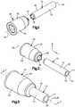
Fig. 6 is a isometric view of a pipe fitting, according to another embodiment of the disclosure; and -
Fig. 7 is an isometric cross-section view of the pipe fitting illustrated inFig. 6 , along line 7-7. - Embodiments of the disclosure will now be described in detail with reference to the drawings, wherein like reference numbers refer to like elements throughout, unless specified otherwise. Certain terminology is used in the following description for convenience only and is not limiting. The term "plurality", as used herein, means more than one. The terms "a portion" and "at least a portion" of a structure include the entirety of the structure. Reference herein to a first structure abutting a second structure refers to the first structure directly contacting the second structure, and precludes an intermediate structure or surface between the first structure and the second structure. The term "aligned" as used herein in reference to two elements in, along, or with respect to a direction means a straight line that passes through one of the elements and that is parallel to the direction will also pass through the other of the two elements. The term "between" as used herein in reference to a first element being between a second element and a third element with respect to a direction means that the first element is closer to the second element as measured along the direction than the third element is to the second element as measured along the direction. The term "between" includes, but does not require that the first, second, and third elements be aligned along the direction.
- Certain features of the disclosure which are described herein in the context of separate embodiments may also be provided in combination in a single embodiment. Conversely, various features of the disclosure that are described in the context of a single embodiment may also be provided separately or in any subcombination.
- Referring to
Figs. 1 to 4 , apipe 10 configured to transport a substance such as a liquid, a gas, or both through thepipe 10 includes apipe body 12 and a pipe throughbore 14 that extends through thepipe body 12. Thepipe body 12 may extend along apipe axis 16. As shown in the illustrated embodiment, thepipe axis 16 may be a central axis about which thepipe body 12 is centered. Thepipe body 12 further includes a pipeouter surface 18 and a pipeinner surface 19. The pipeinner surface 19 defines the pipe throughbore 14. In certain situations it may be beneficial to couple a pipe fitting 20 to thepipe 10. For example, it may be desirable to block off or cap an end of thepipe 10 such that the substance is prevented from exiting thepipe 10 and spilling into the surrounding environment. It may further be desirable to couple thepipe 10 to another pipe such that the substance is transported from thepipe 10 to the other pipe without spilling into the surrounding environment. - The pipe fitting 20 includes a
body 22 that extends along apipe fitting axis 24. As shown in the illustrated embodiment, theaxis 24 may be a central axis about which thebody 22 is centered. A radial or polar coordinate system is provided and described herein. The polar coordinate system includes a two dimensional radial plane that is centered on and normal to the axis 23. The polar coordinate system defines a longitudinal direction L that extends along a direction parallel to theaxis 24. The polar coordinate system defines a radial direction R that extends from theaxis 24 along the radial plane, such that the radial direction R is perpendicular to the longitudinal direction L. The words "inner" and "outer" designate locations closer to and farther away from theaxis 24, respectively. - The
body 22 includes ashell 26 and astiffener 28 that is at least partially enclosed within a shell throughhole 30 that is defined by theshell 26 such that thestiffener 28 is positioned closer to theaxis 24 than theshell 26 is positioned to theaxis 24 with respect to the radial direction R. Theshell 26 includes a shellouter surface 32 that defines an outer perimeter of thebody 22, and the shell further includes a shellinner surface 34 that defines the shell throughhole 30. Theshell 26 includes a shellfirst end 29 and a shellsecond end 31 that is spaced from the shellfirst end 29 along the longitudinal direction L. As shown in the illustrated embodiment, theshell 26 terminates along the longitudinal direction L at the shellfirst end 29 and the shellsecond end 31, and the shell throughhole 30 extends through both the shellfirst end 29 and the shellsecond end 31. - The
stiffener 28 includes a stiffenerouter surface 36 that faces the shellinner surface 34, and the stiffener further includes a stiffenerinner surface 38 that defines a stiffener throughhole 40. Thestiffener 28 includes afirst end 42 and asecond end 44 that is spaced from thefirst end 42 along the longitudinal direction L. As shown in the illustrated embodiment, thestiffener 28 terminates along the longitudinal direction L at thefirst end 42 and thesecond end 44, and the stiffener throughhole 40 extends through both thefirst end 42 and thesecond end 44. Thestiffener 28 further includes astiffener recess 46 defined by the stiffenerouter surface 36. Thestiffener recess 46 is configured to receive astiffener seal member 48, for example an O-ring. The pipe fitting 20 includes apocket 47 positioned between and defined by the stiffenerouter surface 36 and the shellinner surface 34. - The
body 22 further includes a grippingassembly 50 configured to restrict, for example prevent, relative movement of thepipe 10 and the pipe fitting 20 along the longitudinal direction L once thepipe 10 and the pipe fitting 20 are coupled. The grippingassembly 50 may include a grippingcollet 52, a grippingring 60, or both poisoned within the shell throughhole 30 between the shellinner surface 34 and the stiffenerouter surface 36 with respect to the radial direction R. The grippingcollet 52 includes a taperedouter surface 54 and a toothedinner surface 56. The grippingring 60 includes anouter surface 62 and a toothedinner surface 64, the toothedinner surface 64 including at least onetooth 66 configured to engage the pipeouter surface 18 when the pipe fitting 20 is coupled to thepipe 10. - According to one embodiment of the disclosure the gripping
assembly 50 may further include athrust washer 65 positioned between theshell seal member 68 and the grippingcollet 52 to prevent movement of theshell seal member 68 into contact with movable or flexible portions of the grippingcollet 52 which may result in damage to theshell seal member 68. - The
body 22 further includes ashell seal member 68 and a shell-stiffener seal member 70. Theshell seal member 68 may be positioned between the grippingcollet 52 and thegripping ring 60 with respect to the longitudinal direction L. Theshell seal member 68 is further positioned between thestiffener seal member 48 and the shell-stiffener seal member 70 with respect to the longitudinal direction L. - The shell-
stiffener seal member 70 may include abracket 72, afirst seal member 74, for example a first O-ring, and asecond seal member 76, for example a second O-ring. Thebracket 72 may define afirst bracket recess 78 and asecond bracket recess 80, each of thefirst bracket recess 78 and thesecond bracket recess 80 configured to receive one of thefirst seal member 74 and thesecond seal member 76. As shown in the illustrated embodiment, thefirst bracket recess 78 and thesecond bracket recess 80 are aligned with respect to the radial direction R such that when thefirst seal member 74 is positioned within thefirst bracket recess 78 and thesecond seal member 76 is positioned within thesecond bracket recess 80, thefirst seal member 74 and thesecond seal member 76 are aligned with respect to the radial direction R. - The
bracket 72 may define an "H shape" and, according to one aspect of the disclosure, thebracket 72 may include afirst portion 82 and asecond portion 84 that cooperatively define the "H shape." As shown in the illustrated embodiment, thefirst portion 82 and thesecond portion 84 may each define a "T shape" that when coupled together form the "H shape." The shell-stiffener seal member 70 may be assembled by placing thefirst seal member 74 in a portion of thefirst bracket recess 78 that is defined by thefirst portion 82, by placing thesecond seal member 76 in a portion of thesecond bracket recess 80 that is defined by thefirst portion 82, and then coupling thefirst portion 82 and thesecond portion 84. Coupling thefirst portion 82 and thesecond portion 84 may include, as one example, sonic welding. - Referring to
Fig. 5 , another embodiment of the shell-stiffener seal member 70 includes abracket 172 that does not define an "H shape." As shown in the illustrated embodiment, thebracket 172 may define a ring shape with a surface 176 that faces in the longitudinal direction L. - Referring again to
Figs. 1 to 4 , the pipe fitting 20 defines an assembled configuration in which the shell-stiffener seal member 70 is positioned both between thefirst end 42 of thestiffener 28 and thegripping ring 60 with respect to the longitudinal direction L and in thepocket 47. In the assembled configuration thefirst seal member 74 is compressed and forms a seal between thebracket 72 and the shellinner surface 34 and thesecond seal member 76 is compressed and forms a seal between thebracket 72 and the stiffenerouter surface 36, thereby forming a seal within thepocket 47 between the shellinner surface 34 and the stiffenerouter surface 36. - The
stiffener 28, according to one embodiment, may include afirst portion 49 and asecond portion 51, thesecond portion 51 spaced from thefirst portion 49 such that thestiffener recess 46 is between thefirst portion 49 and thesecond portion 51 with respect to the longitudinal direction L. Thestiffener 28 may include a first outer diameter D1 defined by the stiffenerouter surface 36 measured at alocation 53 in thefirst portion 49 that is contacted by thesecond seal member 76. Thestiffener 28 may further include a second outer diameter D2 that is defined by the stiffenerouter surface 36 measured at alocation 55 in thesecond portion 51. As shown in the illustrated embodiment, the first outer diameter D1 may be equal to the second outer diameter D2. - As shown in the illustrated embodiment, the shell-
stiffener seal member 70 is not confined within a channel that prevents movement of the shell-stiffener seal member 70 relative to theshell 26, thestiffener 28, or both along the longitudinal direction L. Thus, according to one aspect of the disclosure in the assembled configuration the shell-stiffener seal member 70 is translatable relative to theshell 26, thestiffener 28, or both along the longitudinal direction L. - The pipe fitting 20 is configured to be coupled to the
pipe 10 to define a coupled configuration. In the coupled configuration thestiffener 28 is positioned within the pipe throughbore 14 such that thestiffener seal member 48 is compressed between and forms a seal between the stiffenerouter surface 36 and the pipeinner surface 19, a portion of thepipe 10 is positioned in thepocket 47 such that thestiffener seal member 48 is compressed between and forms a seal between the shellinner surface 34 and the pipeouter surface 18, and the shell-stiffener seal member 70 is compressed between and forms a seal between the shellinner surface 34 and the stiffenerouter surface 36. - According to one embodiment, the
bracket 72 may be stiffer than at least one of thefirst seal member 74 and thesecond seal member 76. For example the shell-stiffener seal member 70 may be configured such that an amount of force that, if applied to thefirst seal member 74 would deform thefirst seal member 74 would not deform thebracket 72. The shell-stiffener seal member 70 with thebracket 72 as described above may improve the process of coupling the pipe fitting 20 to thepipe 10. For example, anend 15 of thepipe 10 may be chamfered prior to insertion of thepipe 10 into thepocket 47. Thebracket 72 is configured to receive an impact of thechamfered end 15 without deformation or damage. - If the
chamfered end 15 damages the shell-stiffener seal member 70, there might not be an adequate seal created between theshell 26 and thestiffener 28. If thechamfered end 15 deforms the shell-stiffener seal member 70, thepipe 10 may not be inserted to the correct depth. Inserting thepipe 10 to the correct depth within thepocket 47 may be important to form an effective seal. For example, the correct depth may be determined based on location of scratches or defects on the pipeouter surface 18, and ensuring that theshell seal member 68 is not aligned with the scratches or defects. An installer of the pipe fitting 20 may mark theouter pipe surface 18 at a location that is aligned with the shellsecond end 31 when thepipe 10 is inserted within thepocket 4 to the correct depth. Thus, the shell-stiffener seal member 70 including thebracket 72 positioned such that thechamfered end 15 does not impact either of thefirst seal member 74 or thesecond seal member 76 may result in a more efficient coupling process and a more effective seal for thepipe 10 and thepipe fitting 20. - The inclusion of the shell-
stiffener seal member 70 removes the problem of damage, such as scratches, on the pipeouter surface 18 preventing an adequate seal being formed between the shellinner surface 34 and the pipeouter surface 18. The shell-stiffener seal member 70 forms a seal independent of thepipe 10, therefore rendering any damage to the pipeouter surface 18 moot to the formation of an adequate seal. Additionally, the radial alignment of thefirst seal member 74 and thesecond seal member 76 may result in an effective seal between theshell 26 and thestiffener 28 that is more resilient and resistant to damage and leaks as a result of bending loads or other forces applied to the coupledpipe 10 than a seal member without a radially aligned plurality of seal members, for example a single seal member such as an O-ring. - Referring to
Fig. 5 , in the assembled configuration the shell-stiffener seal member 174 is compressed and forms a seal between the shellinner surface 34 and the stiffenerouter surface 36. Thebracket 172 may be positioned relative to the shell-stiffener seal member 174 and stiffer than the shell-stiffener seal member 174 similarly to thebracket 72 and first andsecond seal members - Referring again to
Figs. 1 to 4 , when thepipe 10 and the pipe fitting 20 are in the coupled configuration attempted withdrawal of thepipe 10 from thepocket 47 in the longitudinal direction L causes theteeth 66, which are directly abutting the pipeouter surface 18 to move the grippingassembly 50 in the longitudinal direction L, which results in thepipe 10 being more firmly gripped by the grippingcollet 52 as described below. - As the gripping
assembly 50 moves relative to theshell 26 in the longitudinal direction L, the taperedouter surface 54 of the gripping assembly abuts and is compressed radially toward theaxis 24 by a tapered portion of the shellinner surface 34. The radial compression results in the grippingcollet 52 exerting a gripping force on thepipe 10 thereby preventing further movement of thepipe 10 relative to the grippingassembly 50 in the longitudinal direction L. - The shell
first end 29 may be configured to be coupled to a plurality of other members of fittings including but not limited to: a valve, a plug, and another pipe fitting. Referring toFigs. 6 and 7 , a pipe fitting 120 may include two identical ones of the pipe fitting 20 coupled to one another. As shown in the illustrated embodiment, the pipe fitting 120 includes a first pipe fitting 20a coupled to a second pipe fitting 20b, for example by connecting the shell first ends 29 of the first pipe fitting 20a and the second pipe fitting 20b. The description of the pipe fitting 20 herein is applicable to each of the first pipe fitting 20a and the second pipe fitting 20b. According to one embodiment, the first ends 29 may be connected by placing a hot member in contact with each of the first ends 29 until each of the first ends 29 begins to melt, then removing the hot member and forcing the first ends 29 into direct contact such that as the first ends 29 cool, the first ends solidify into a single piece thereby forming thepipe fitting 120. - The pipe fitting 120 is configured to couple a
first pipe 10a to asecond pipe 10b. As shown in the illustrated embodiment, the first pipe fitting 20a is coupled to thefirst pipe 10a to form a coupled configuration as described above, and the second pipe fitting 20b is coupled to thesecond pipe 10b to form a coupled configuration as described above. The resulting coupled configuration allows the substance to flow through thefirst pipe 10a, through the pipe fitting 120, and through thesecond pipe 10b without leaking any of the substance into the surrounding environment. - It will be appreciated that the foregoing description provides examples of the disclosed system and technique. However, it is contemplated that other implementations of the disclosure may differ in detail from the foregoing examples. All references to the disclosure or examples thereof are intended to reference the particular example being discussed at that point and are not intended to imply any limitation as to the scope of the disclosure more generally. All language of distinction and disparagement with respect to certain features is intended to indicate a lack of preference for those features, but not to exclude such from the scope of the disclosure entirely unless otherwise indicated.
- Although the disclosure has been described in detail, it should be understood that various changes, substitutions, and alterations can be made herein without departing from the spirit and scope of the invention as defined by the appended claims. Moreover, the scope of the present disclosure is not intended to be limited to the particular embodiments described in the specification. As one of ordinary skill in the art will readily appreciate from the disclosure of the present invention, processes, machines, manufacture, composition of matter, means, methods, or steps, presently existing or later to be developed that perform substantially the same function or achieve substantially the same result as the corresponding embodiments described herein may be utilized according to the present disclosure.
Preferred Embodiments of the Present Invention are as Numbered Below: - 1. A pipe fitting configured to be coupled to a pipe, the pipe fitting comprising:
- a body that is elongate along a central axis that extends in a longitudinal direction, the body including:
- a shell and a shell through hole that extends through the shell in the longitudinal direction, the shell having a shell inner surface that defines the shell through hole;
- a stiffener positioned within the shell through hole, the stiffener including a stiffener outer surface that faces the shell inner surface such that the stiffener outer surface and the shell inner surface cooperate to define a pocket configured to receive the pipe; and
- a shell-stiffener seal member including a bracket, a first seal member, and a second seal member, the shell-stiffener seal member positioned in the pocket such that: 1) the first seal member is compressed and forms a seal between the bracket and the shell inner surface, 2) the second seal member is compressed and forms a seal between the bracket and the stiffener outer surface, and 3) the first seal member and the second seal member are aligned in a radial direction, which is perpendicular to the longitudinal direction.
- a body that is elongate along a central axis that extends in a longitudinal direction, the body including:
- 2. The pipe fitting of 1, wherein the bracket defines a first bracket recess configured to receive the first seal member, the bracket defines a second bracket recess configured to receive the second seal member, and the first bracket recess is aligned with the second bracket recess in the radial direction.
- 3. The pipe fitting of 2, wherein the bracket is substantially H shaped.
- 4. The pipe fitting of 2, wherein the bracket includes a first portion and a second portion, the first portion defines a first portion of both the first bracket recess and the second bracket recess, the second portion defines a second portion of both the first bracket recess and the second bracket recess, and the first portion and the second portion are configured to be coupled together such that the first portion and the second portion cooperatively define both the first bracket recess and the second bracket recess.
- 5. The pipe fitting of 4, wherein at least one of the first portion and the second portion is substantially T shaped.
- 6. The pipe fitting of 1, wherein the stiffener outer surface defines a stiffener recess that is configured to receive a stiffener seal member, the stiffener seal member is configured to compress and form a seal between an inner surface of the pipe and the stiffener outer surface when the pipe is positioned in the pocket.
- 7. The pipe fitting of 6, wherein the stiffener includes a first portion and a second portion, the second portion spaced from the first portion such that the stiffener recess is between the first portion and the second portion with respect to the longitudinal direction, the stiffener has a first outer diameter defined by the stiffener outer surface measured at a location in the first portion that is contacted by the second seal member, the stiffener has a second outer diameter that is defined by the stiffener outer surface measured at a location in the second portion, and the first outer diameter is equal to the second outer diameter.
- 8. The pipe fitting of 7, further comprising a shell seal member configured to compress and form a seal between the shell inner surface and an outer surface of the pipe when the pipe is positioned in the pocket.
- 9. The pipe fitting of 8, wherein the shell seal member is positioned between the shell-stiffener seal member and the stiffener seal member with respect to the longitudinal direction.
- 10. The pipe fitting of 1, further comprising a gripping assembly configured to restrict relative movement of the pipe and the pipe fitting along the longitudinal direction when the pipe is positioned in the pocket and coupled to the pipe fitting.
- 11. The pipe fitting of 1, wherein at least one of the first seal member and the second seal member includes an O-ring.
- 12. A pipe fitting configured to be coupled to a pipe, the pipe fitting comprising:
- a body that is elongate along a central axis that extends in a longitudinal direction, the body including:
- a shell and a shell through hole that extends through the shell in the longitudinal direction, the shell having a shell inner surface that defines the shell through hole;
- a stiffener positioned within the shell through hole, the stiffener including a stiffener outer surface that faces the shell inner surface such that the stiffener outer surface and the shell inner surface cooperate to define a pocket configured to receive the pipe, the stiffener outer surface defining a stiffener recess configured to receive a stiffener seal member that is configured to compress and form a seal between an inner surface of the pipe and the stiffener outer surface when the pipe is positioned in the pocket, the stiffener including a first portion and a second portion, the second portion spaced from the first portion such that the stiffener recess is between the first portion and the second portion with respect to the longitudinal direction; and
- a shell-stiffener seal member that is compressed and forms a seal between the shell inner surface and the stiffener outer surface,
- wherein the stiffener has a first outer diameter defined by the stiffener outer surface measured at a location in the first portion that is contacted by the shell-stiffener seal member, the stiffener has a second outer diameter that is defined by the stiffener outer surface measured at a location in the second portion, and the first outer diameter is equal to the second outer diameter.
- a body that is elongate along a central axis that extends in a longitudinal direction, the body including:
- 13. The pipe fitting of 12, wherein the shell-stiffener seal member includes a bracket, a first seal member, and a second seal member, the shell-stiffener seal member positioned in the pocket such that: 1) the first seal member is compressed and forms a seal between the bracket and the shell inner surface, 2) the second seal member is compressed and forms a seal between the bracket and the stiffener outer surface, and 3) the first seal member and the second seal member are aligned in a radial direction, which is perpendicular to the longitudinal direction, and the bracket defines a first bracket recess configured to receive the first seal member, the bracket defines a second bracket recess configured to receive the second seal member, and the first bracket recess is aligned with the second bracket recess in the radial direction.
- 14. The pipe fitting of 13, wherein the bracket is substantially H shaped.
- 15. The pipe fitting of 13, wherein at least one of the first seal member and the second seal member includes an O-ring.
- 16. The pipe fitting of 13, wherein the bracket includes a first portion and a second portion, the first portion defines a first portion of both the first bracket recess and the second bracket recess, the second portion defines a second portion of both the first bracket recess and the second bracket recess, and the first portion and the second portion are configured to be coupled together such that the first portion and the second portion cooperatively define both the first bracket recess and the second bracket recess.
- 17. The pipe fitting of 16, wherein at least one of the first portion and the second portion is substantially T shaped.
- 18. A method of assembling a pipe fitting configured to be coupled to a pipe, the method comprising the steps of:
- positioning a first seal member in a first partial bracket recess defined by a first portion of a bracket;
- positioning a second seal member in a second partial bracket recess defined by the first portion;
- moving a second portion of the bracket relative to the first portion until the first portion is in contact with the second portion such that both: 1) a third partial bracket recess of the second portion cooperates with the first partial bracket recess of the first portion to form a first bracket recess, and 2) a fourth partial bracket recess of the second portion cooperates with the second partial bracket recess of the first portion to form a second bracket recess;
- coupling the first portion to the second portion such that relative movement of the first and second portions is prevented;
- abutting the second seal member with a stiffener outer surface of a stiffener of the pipe fitting;
- positioning the stiffener in a shell through bore defined by an inner surface of a shell of the pipe fitting such that both: 1) the shell inner surface and the stiffener outer surface cooperate to define a pocket configured to receive a pipe, and 2) the first seal member abuts the shell inner surface.
- 19. The method of 18, wherein the coupling step includes the step of sonic welding the first portion to the second portion.
- 20. The method of 18, further comprising the step of heating a first end of the shell; and abutting the heated first end with a second pipe fitting.
Claims (15)
- A pipe fitting (20) configured to be coupled to a pipe (10), the pipe fitting (20) comprising:a body (22) that is elongate along a central axis (24) that extends in a longitudinal direction, the body (22) including:a shell (26) and a shell through hole (30) that extends through the shell (26) in the longitudinal direction, the shell (26) having a shell inner surface (34) that defines the shell through hole (30);a stiffener (28) positioned within the shell through hole (30), the stiffener (28) including a stiffener outer surface (36) that faces the shell inner surface (34) such that the stiffener outer surface (36) and the shell inner surface (34) cooperate to define a pocket (47) configured to receive the pipe (10); anda shell-stiffener seal member (70) including a bracket (72), a first seal member (74), and a second seal member (76), the shell-stiffener seal member (70) positioned in the pocket (47) such that: 1) the first seal member (74) is compressed and forms a seal between the bracket (72) and the shell inner surface (34), 2) the second seal member (76) is compressed and forms a seal between the bracket (72) and the stiffener outer surface (36), and 3) the first seal member (74) and the second seal member (74) are aligned in a radial direction, which is perpendicular to the longitudinal direction.
- The pipe fitting (20) of claim 1, wherein the bracket (72) defines a first bracket recess (78) configured to receive the first seal member (74), the bracket (72) defines a second bracket recess (80) configured to receive the second seal member (76), and the first bracket recess (78) is aligned with the second bracket recess (80) in the radial direction.
- The pipe fitting (20) of claim 2, wherein the bracket (72) is substantially H shaped.
- The pipe fitting (20) of claim 2, wherein the bracket (72) includes a first portion (82) and a second portion (84), the first portion (82) defines a first portion of both the first bracket recess (78) and the second bracket recess (80), the second portion (84) defines a second portion of both the first bracket recess (78) and the second bracket recess (80), and the first portion (82) and the second portion (84) are configured to be coupled together such that the first portion (82) and the second portion (84) cooperatively define both the first bracket recess (78) and the second bracket recess (80).
- The pipe fitting (20) of claim 4, wherein at least one of the first portion (82) and the second portion (84) is substantially T shaped.
- The pipe fitting (20) of claim 1, wherein the stiffener outer surface (36) defines a stiffener recess (46) that is configured to receive a stiffener seal member (48), the stiffener seal member (48) is configured to compress and form a seal between an inner surface (19) of the pipe (10) and the stiffener outer surface (36) when the pipe (10) is positioned in the pocket (47).
- The pipe fitting (20) of claim 6, wherein the stiffener (28) includes a first portion (49) and a second portion (51), the second portion (51) spaced from the first portion (49) such that the stiffener recess (46) is between the first portion (49) and the second portion (51) with respect to the longitudinal direction, the stiffener (28) has a first outer diameter defined by the stiffener outer surface (36) measured at a location (53) in the first portion (49) that is contacted by the second seal member (76), the stiffener (28) has a second outer diameter that is defined by the stiffener outer surface (36) measured at a location (55) in the second portion (51), and the first outer diameter is equal to the second outer diameter.
- The pipe fitting (20) of claim 7, further comprising a shell seal member (68) configured to compress and form a seal between the shell inner surface (34) and an outer surface (18) of the pipe (10) when the pipe (10) is positioned in the pocket (47).
- The pipe fitting (20) of claim 8, wherein the shell seal member (68) is positioned between the shell-stiffener seal member (70) and the stiffener seal member (48) with respect to the longitudinal direction.
- The pipe fitting (20) of claim 1, further comprising a gripping assembly (50) configured to restrict relative movement of the pipe (10) and the pipe fitting (20) along the longitudinal direction when the pipe (10) is positioned in the pocket (47) and coupled to the pipe fitting (20).
- A pipe fitting (20) configured to be coupled to a pipe (10), the pipe fitting (20) comprising:a body (22) that is elongate along a central axis (24) that extends in a longitudinal direction, the body (22) including:a shell (26) and a shell through hole (30) that extends through the shell (26) in the longitudinal direction, the shell (26) having a shell inner surface (34) that defines the shell through hole (30);a stiffener (28) positioned within the shell through hole (30), the stiffener (28) including a stiffener outer surface (36) that faces the shell inner surface (34) such that the stiffener outer surface (36) and the shell inner surface (34) cooperate to define a pocket (47) configured to receive the pipe (10), the stiffener outer surface (36) defining a stiffener recess (46) configured to receive a stiffener seal member (48) that is configured to compress and form a seal between an inner surface (19) of the pipe (10) and the stiffener outer surface (36) when the pipe (10) is positioned in the pocket (47), the stiffener (28) including a first portion (49) and a second portion (51), the second portion (51) spaced from the first portion (49) such that the stiffener recess (46) is between the first portion (49) and the second portion (51) with respect to the longitudinal direction; anda shell-stiffener seal member (70) that is compressed and forms a seal between the shell inner surface (34) and the stiffener outer surface (36),wherein the stiffener (28) has a first outer diameter defined by the stiffener outer surface (36) measured at a location (53) in the first portion (49) that is contacted by the shell-stiffener seal member (70), the stiffener (28) has a second outer diameter that is defined by the stiffener outer surface (36) measured at a location (55) in the second portion (51), and the first outer diameter is equal to the second outer diameter.
- The pipe fitting (20) of claim 11, wherein the shell-stiffener seal member (70) includes a bracket (72), a first seal member (74), and a second seal member (76), the shell-stiffener seal member (70) positioned in the pocket (47) such that: 1) the first seal member (74) is compressed and forms a seal between the bracket (72) and the shell inner surface (34), 2) the second seal member (76) is compressed and forms a seal between the bracket (72) and the stiffener outer surface (36), and 3) the first seal member (74) and the second seal member (76) are aligned in a radial direction, which is perpendicular to the longitudinal direction, and the bracket (72) defines a first bracket recess (78) configured to receive the first seal member (74), the bracket (72) defines a second bracket recess (80) configured to receive the second seal member (76), and the first bracket recess (78) is aligned with the second bracket recess (80) in the radial direction.
- The pipe fitting (20) of claim 12, wherein the bracket (72) is substantially H shaped.
- The pipe fitting (20) of claim 12, wherein the bracket (72) includes a first portion (82) and a second portion (84), the first portion (82) defines a first portion of both the first bracket recess (78) and the second bracket recess (80), the second portion (84) defines a second portion of both the first bracket recess (78) and the second bracket recess (80), and the first portion (82) and the second portion (84) are configured to be coupled together such that the first portion (82) and the second portion (84) cooperatively define both the first bracket recess (78) and the second bracket recess (80).
- The pipe fitting (20) of claim 14, wherein at least one of the first portion (82) and the second portion (84) is substantially T shaped.
Applications Claiming Priority (1)
| Application Number | Priority Date | Filing Date | Title |
|---|---|---|---|
| US15/291,442 US10174874B2 (en) | 2016-10-12 | 2016-10-12 | Pipe fitting with inner and outer seals |
Publications (3)
| Publication Number | Publication Date |
|---|---|
| EP3309439A2 true EP3309439A2 (en) | 2018-04-18 |
| EP3309439A3 EP3309439A3 (en) | 2018-05-16 |
| EP3309439B1 EP3309439B1 (en) | 2019-10-09 |
Family
ID=59558270
Family Applications (1)
| Application Number | Title | Priority Date | Filing Date |
|---|---|---|---|
| EP17184897.1A Active EP3309439B1 (en) | 2016-10-12 | 2017-08-04 | Pipe fitting with inner and outer seals |
Country Status (2)
| Country | Link |
|---|---|
| US (1) | US10174874B2 (en) |
| EP (1) | EP3309439B1 (en) |
Families Citing this family (4)
| Publication number | Priority date | Publication date | Assignee | Title |
|---|---|---|---|---|
| IL231306A0 (en) | 2014-03-04 | 2014-08-31 | Huliot A C S Ltd | Electromagnetic induction welding of fluid distribution systems |
| GB201502172D0 (en) * | 2015-02-10 | 2015-03-25 | Irwin William J And Canning William A | A pipe coupling |
| IL262382A (en) * | 2018-10-15 | 2018-11-29 | Huliot A C S Ltd | Installation fittings for use in domestic water supply pipe systems |
| US11725763B2 (en) * | 2019-11-21 | 2023-08-15 | Honeywell International Inc. | Pipe fitting with inner and outer seals |
Citations (1)
| Publication number | Priority date | Publication date | Assignee | Title |
|---|---|---|---|---|
| WO2004063614A2 (en) | 2003-01-08 | 2004-07-29 | California Marine Technologies, Llc | Stabilizer-seal-insert for push-in tube couplings |
Family Cites Families (20)
| Publication number | Priority date | Publication date | Assignee | Title |
|---|---|---|---|---|
| US4106779A (en) * | 1975-03-03 | 1978-08-15 | Nl Hycalog | Automatic sequential dual action sealing system |
| US4628965A (en) * | 1983-07-29 | 1986-12-16 | Perfection Corporation | Stab-type coupling |
| US4664427A (en) * | 1985-04-01 | 1987-05-12 | Master Industries, Inc. | Quick connect fitting |
| EP0628760B1 (en) * | 1993-06-14 | 1998-09-02 | Tokai Rubber Industries, Ltd. | Tube fitting |
| US5547228A (en) | 1994-04-01 | 1996-08-20 | Abbema; Wiliam D. | Cylindrical corrosion barrier for pipe connections |
| US5480196A (en) | 1994-08-15 | 1996-01-02 | American Cast Iron Pipe Company | Ductile iron pipe joint employing a coupling and coupling therefor |
| US5692785A (en) | 1995-11-29 | 1997-12-02 | Continental Industries, Inc. | Plastic pipe coupler with internal sealer |
| US5791698A (en) | 1995-11-29 | 1998-08-11 | Continental Industries, Inc. | Plastic pipe coupler with internal sealer |
| US6050613A (en) | 1996-04-01 | 2000-04-18 | Continental Industries, Inc. | Combined plastic pipe coupler and end plug |
| US6371531B1 (en) * | 1997-01-13 | 2002-04-16 | Perfection Corporation | Stab-type coupling with collet having locking ribs and rotation prevention member |
| US6142538A (en) * | 1998-07-28 | 2000-11-07 | Perfection Corporation | Stab-type coupling with conduit inner diameter seal |
| GB9828423D0 (en) | 1998-12-24 | 1999-02-17 | Technology The | Pipe coupling |
| US6286877B1 (en) | 2000-04-17 | 2001-09-11 | Anthony Manufacturing Corp. Industrial Prod. Div. | Dual seal pipe coupling |
| US6877777B1 (en) | 2002-04-16 | 2005-04-12 | Continental Industries, Inc. | Insertion sleeve and stiffener for a pipe coupling |
| US7753413B2 (en) | 2003-01-28 | 2010-07-13 | Denso Corporation | Vapour-compression type refrigerating machine and double pipe structure and double pipe joint structure preferably used therefor |
| US7740248B2 (en) * | 2003-09-18 | 2010-06-22 | Cameron International Corporation | Annular seal |
| JP2005147187A (en) | 2003-11-12 | 2005-06-09 | Mym Corp | Pipe joint |
| TW200604096A (en) | 2004-03-24 | 2006-02-01 | Kobe Steel Ltd | Glass-like carbon deformed molded article, process for producing the same, and joint structure for jointing a connecting member to a glass-like carbon hollow molded article |
| NL1027253C2 (en) | 2004-10-14 | 2006-04-19 | Wavin Bv | Pipe coupling. |
| DE102014115092A1 (en) | 2014-10-16 | 2016-04-21 | Stefan Postler | Connecting part, method for performing a connection and connection between a connecting part and a pipe part |
-
2016
- 2016-10-12 US US15/291,442 patent/US10174874B2/en active Active
-
2017
- 2017-08-04 EP EP17184897.1A patent/EP3309439B1/en active Active
Patent Citations (1)
| Publication number | Priority date | Publication date | Assignee | Title |
|---|---|---|---|---|
| WO2004063614A2 (en) | 2003-01-08 | 2004-07-29 | California Marine Technologies, Llc | Stabilizer-seal-insert for push-in tube couplings |
Also Published As
| Publication number | Publication date |
|---|---|
| US10174874B2 (en) | 2019-01-08 |
| US20180100612A1 (en) | 2018-04-12 |
| EP3309439A3 (en) | 2018-05-16 |
| EP3309439B1 (en) | 2019-10-09 |
Similar Documents
| Publication | Publication Date | Title |
|---|---|---|
| EP3309439A2 (en) | Pipe fitting with inner and outer seals | |
| US20080191479A1 (en) | Screw Joint for Oil Well Tubing | |
| US20150285420A1 (en) | Coupling and joint for fixedly and sealingly securing components to one another | |
| KR20190104641A (en) | Push to connect conduit fitting with ferrule | |
| US20060145479A1 (en) | Pipe liner connector | |
| CA2897916A1 (en) | Fitting for joining tubes and method of joining tubes | |
| US20130154260A1 (en) | Coupling And Joint For Fixedly And Sealingly Securing Components To One Another | |
| KR20080101703A (en) | Non-serviceable fluid coupling | |
| EP2677225A2 (en) | Coupling and joint for fixedly and sealingly securing components to one another | |
| US8782872B2 (en) | Multi-piece piping connector using grooves and method of connecting pipe using the same | |
| JP7063620B2 (en) | Fittings for connecting to tubular elements, pipe fittings, and fitting methods for connecting to tubular elements | |
| US7273237B1 (en) | Union coupler assembly for coolant lines | |
| EP3306165B1 (en) | Threaded retainer | |
| KR101515841B1 (en) | Conduit Connecting Apparatus Having a Bush | |
| US10794517B2 (en) | System, method and apparatus for expansion coupling for pipes with sheathed grooves | |
| US11725763B2 (en) | Pipe fitting with inner and outer seals | |
| JP2007170658A (en) | Pipe joint | |
| EP2096347A1 (en) | Method for joining together steel pipes for conveying fluids under pressure | |
| US20060054721A1 (en) | Connection assembly for high-pressure pipes in vehicle air conditioning units | |
| JP6113312B1 (en) | Pipe connection structure | |
| KR101435576B1 (en) | A Bush and Conduit Connecting Apparatus Having the Same | |
| EP3121500B1 (en) | Coupling for fixedly and sealingly securing components to one another with improved sealing | |
| KR102164806B1 (en) | Coupling and joint for fixedly and sealingly securing components to one another | |
| JPH11351465A (en) | Pipe joint | |
| US11927286B2 (en) | Crimped end connection for flexible hose |
Legal Events
| Date | Code | Title | Description |
|---|---|---|---|
| PUAI | Public reference made under article 153(3) epc to a published international application that has entered the european phase |
Free format text: ORIGINAL CODE: 0009012 |
|
| STAA | Information on the status of an ep patent application or granted ep patent |
Free format text: STATUS: REQUEST FOR EXAMINATION WAS MADE |
|
| PUAL | Search report despatched |
Free format text: ORIGINAL CODE: 0009013 |
|
| 17P | Request for examination filed |
Effective date: 20170804 |
|
| AK | Designated contracting states |
Kind code of ref document: A2 Designated state(s): AL AT BE BG CH CY CZ DE DK EE ES FI FR GB GR HR HU IE IS IT LI LT LU LV MC MK MT NL NO PL PT RO RS SE SI SK SM TR |
|
| AX | Request for extension of the european patent |
Extension state: BA ME |
|
| AK | Designated contracting states |
Kind code of ref document: A3 Designated state(s): AL AT BE BG CH CY CZ DE DK EE ES FI FR GB GR HR HU IE IS IT LI LT LU LV MC MK MT NL NO PL PT RO RS SE SI SK SM TR |
|
| AX | Request for extension of the european patent |
Extension state: BA ME |
|
| RIC1 | Information provided on ipc code assigned before grant |
Ipc: F16L 37/092 20060101AFI20180411BHEP Ipc: F16L 33/22 20060101ALN20180411BHEP |
|
| GRAJ | Information related to disapproval of communication of intention to grant by the applicant or resumption of examination proceedings by the epo deleted |
Free format text: ORIGINAL CODE: EPIDOSDIGR1 |
|
| STAA | Information on the status of an ep patent application or granted ep patent |
Free format text: STATUS: GRANT OF PATENT IS INTENDED |
|
| RIC1 | Information provided on ipc code assigned before grant |
Ipc: F16L 33/22 20060101ALN20190205BHEP Ipc: F16L 37/092 20060101AFI20190205BHEP |
|
| GRAP | Despatch of communication of intention to grant a patent |
Free format text: ORIGINAL CODE: EPIDOSNIGR1 |
|
| INTG | Intention to grant announced |
Effective date: 20190318 |
|
| GRAS | Grant fee paid |
Free format text: ORIGINAL CODE: EPIDOSNIGR3 |
|
| GRAA | (expected) grant |
Free format text: ORIGINAL CODE: 0009210 |
|
| STAA | Information on the status of an ep patent application or granted ep patent |
Free format text: STATUS: THE PATENT HAS BEEN GRANTED |
|
| AK | Designated contracting states |
Kind code of ref document: B1 Designated state(s): AL AT BE BG CH CY CZ DE DK EE ES FI FR GB GR HR HU IE IS IT LI LT LU LV MC MK MT NL NO PL PT RO RS SE SI SK SM TR |
|
| REG | Reference to a national code |
Ref country code: GB Ref legal event code: FG4D |
|
| REG | Reference to a national code |
Ref country code: CH Ref legal event code: EP |
|
| REG | Reference to a national code |
Ref country code: DE Ref legal event code: R096 Ref document number: 602017007588 Country of ref document: DE |
|
| REG | Reference to a national code |
Ref country code: IE Ref legal event code: FG4D |
|
| REG | Reference to a national code |
Ref country code: AT Ref legal event code: REF Ref document number: 1189238 Country of ref document: AT Kind code of ref document: T Effective date: 20191115 |
|
| REG | Reference to a national code |
Ref country code: NL Ref legal event code: MP Effective date: 20191009 |
|
| REG | Reference to a national code |
Ref country code: LT Ref legal event code: MG4D |
|
| REG | Reference to a national code |
Ref country code: AT Ref legal event code: MK05 Ref document number: 1189238 Country of ref document: AT Kind code of ref document: T Effective date: 20191009 |
|
| PG25 | Lapsed in a contracting state [announced via postgrant information from national office to epo] |
Ref country code: PL Free format text: LAPSE BECAUSE OF FAILURE TO SUBMIT A TRANSLATION OF THE DESCRIPTION OR TO PAY THE FEE WITHIN THE PRESCRIBED TIME-LIMIT Effective date: 20191009 Ref country code: NO Free format text: LAPSE BECAUSE OF FAILURE TO SUBMIT A TRANSLATION OF THE DESCRIPTION OR TO PAY THE FEE WITHIN THE PRESCRIBED TIME-LIMIT Effective date: 20200109 Ref country code: AT Free format text: LAPSE BECAUSE OF FAILURE TO SUBMIT A TRANSLATION OF THE DESCRIPTION OR TO PAY THE FEE WITHIN THE PRESCRIBED TIME-LIMIT Effective date: 20191009 Ref country code: LV Free format text: LAPSE BECAUSE OF FAILURE TO SUBMIT A TRANSLATION OF THE DESCRIPTION OR TO PAY THE FEE WITHIN THE PRESCRIBED TIME-LIMIT Effective date: 20191009 Ref country code: SE Free format text: LAPSE BECAUSE OF FAILURE TO SUBMIT A TRANSLATION OF THE DESCRIPTION OR TO PAY THE FEE WITHIN THE PRESCRIBED TIME-LIMIT Effective date: 20191009 Ref country code: FI Free format text: LAPSE BECAUSE OF FAILURE TO SUBMIT A TRANSLATION OF THE DESCRIPTION OR TO PAY THE FEE WITHIN THE PRESCRIBED TIME-LIMIT Effective date: 20191009 Ref country code: BG Free format text: LAPSE BECAUSE OF FAILURE TO SUBMIT A TRANSLATION OF THE DESCRIPTION OR TO PAY THE FEE WITHIN THE PRESCRIBED TIME-LIMIT Effective date: 20200109 Ref country code: GR Free format text: LAPSE BECAUSE OF FAILURE TO SUBMIT A TRANSLATION OF THE DESCRIPTION OR TO PAY THE FEE WITHIN THE PRESCRIBED TIME-LIMIT Effective date: 20200110 Ref country code: PT Free format text: LAPSE BECAUSE OF FAILURE TO SUBMIT A TRANSLATION OF THE DESCRIPTION OR TO PAY THE FEE WITHIN THE PRESCRIBED TIME-LIMIT Effective date: 20200210 Ref country code: ES Free format text: LAPSE BECAUSE OF FAILURE TO SUBMIT A TRANSLATION OF THE DESCRIPTION OR TO PAY THE FEE WITHIN THE PRESCRIBED TIME-LIMIT Effective date: 20191009 Ref country code: NL Free format text: LAPSE BECAUSE OF FAILURE TO SUBMIT A TRANSLATION OF THE DESCRIPTION OR TO PAY THE FEE WITHIN THE PRESCRIBED TIME-LIMIT Effective date: 20191009 Ref country code: LT Free format text: LAPSE BECAUSE OF FAILURE TO SUBMIT A TRANSLATION OF THE DESCRIPTION OR TO PAY THE FEE WITHIN THE PRESCRIBED TIME-LIMIT Effective date: 20191009 |
|
| PG25 | Lapsed in a contracting state [announced via postgrant information from national office to epo] |
Ref country code: HR Free format text: LAPSE BECAUSE OF FAILURE TO SUBMIT A TRANSLATION OF THE DESCRIPTION OR TO PAY THE FEE WITHIN THE PRESCRIBED TIME-LIMIT Effective date: 20191009 Ref country code: IS Free format text: LAPSE BECAUSE OF FAILURE TO SUBMIT A TRANSLATION OF THE DESCRIPTION OR TO PAY THE FEE WITHIN THE PRESCRIBED TIME-LIMIT Effective date: 20200224 Ref country code: RS Free format text: LAPSE BECAUSE OF FAILURE TO SUBMIT A TRANSLATION OF THE DESCRIPTION OR TO PAY THE FEE WITHIN THE PRESCRIBED TIME-LIMIT Effective date: 20191009 |
|
| PG25 | Lapsed in a contracting state [announced via postgrant information from national office to epo] |
Ref country code: AL Free format text: LAPSE BECAUSE OF FAILURE TO SUBMIT A TRANSLATION OF THE DESCRIPTION OR TO PAY THE FEE WITHIN THE PRESCRIBED TIME-LIMIT Effective date: 20191009 |
|
| REG | Reference to a national code |
Ref country code: DE Ref legal event code: R097 Ref document number: 602017007588 Country of ref document: DE |
|
| PG2D | Information on lapse in contracting state deleted |
Ref country code: IS |
|
| PG25 | Lapsed in a contracting state [announced via postgrant information from national office to epo] |
Ref country code: CZ Free format text: LAPSE BECAUSE OF FAILURE TO SUBMIT A TRANSLATION OF THE DESCRIPTION OR TO PAY THE FEE WITHIN THE PRESCRIBED TIME-LIMIT Effective date: 20191009 Ref country code: RO Free format text: LAPSE BECAUSE OF FAILURE TO SUBMIT A TRANSLATION OF THE DESCRIPTION OR TO PAY THE FEE WITHIN THE PRESCRIBED TIME-LIMIT Effective date: 20191009 Ref country code: EE Free format text: LAPSE BECAUSE OF FAILURE TO SUBMIT A TRANSLATION OF THE DESCRIPTION OR TO PAY THE FEE WITHIN THE PRESCRIBED TIME-LIMIT Effective date: 20191009 Ref country code: DK Free format text: LAPSE BECAUSE OF FAILURE TO SUBMIT A TRANSLATION OF THE DESCRIPTION OR TO PAY THE FEE WITHIN THE PRESCRIBED TIME-LIMIT Effective date: 20191009 Ref country code: IS Free format text: LAPSE BECAUSE OF FAILURE TO SUBMIT A TRANSLATION OF THE DESCRIPTION OR TO PAY THE FEE WITHIN THE PRESCRIBED TIME-LIMIT Effective date: 20200209 |
|
| PLBE | No opposition filed within time limit |
Free format text: ORIGINAL CODE: 0009261 |
|
| STAA | Information on the status of an ep patent application or granted ep patent |
Free format text: STATUS: NO OPPOSITION FILED WITHIN TIME LIMIT |
|
| PG25 | Lapsed in a contracting state [announced via postgrant information from national office to epo] |
Ref country code: IT Free format text: LAPSE BECAUSE OF FAILURE TO SUBMIT A TRANSLATION OF THE DESCRIPTION OR TO PAY THE FEE WITHIN THE PRESCRIBED TIME-LIMIT Effective date: 20191009 Ref country code: SM Free format text: LAPSE BECAUSE OF FAILURE TO SUBMIT A TRANSLATION OF THE DESCRIPTION OR TO PAY THE FEE WITHIN THE PRESCRIBED TIME-LIMIT Effective date: 20191009 Ref country code: SK Free format text: LAPSE BECAUSE OF FAILURE TO SUBMIT A TRANSLATION OF THE DESCRIPTION OR TO PAY THE FEE WITHIN THE PRESCRIBED TIME-LIMIT Effective date: 20191009 |
|
| 26N | No opposition filed |
Effective date: 20200710 |
|
| PG25 | Lapsed in a contracting state [announced via postgrant information from national office to epo] |
Ref country code: SI Free format text: LAPSE BECAUSE OF FAILURE TO SUBMIT A TRANSLATION OF THE DESCRIPTION OR TO PAY THE FEE WITHIN THE PRESCRIBED TIME-LIMIT Effective date: 20191009 |
|
| PG25 | Lapsed in a contracting state [announced via postgrant information from national office to epo] |
Ref country code: MC Free format text: LAPSE BECAUSE OF FAILURE TO SUBMIT A TRANSLATION OF THE DESCRIPTION OR TO PAY THE FEE WITHIN THE PRESCRIBED TIME-LIMIT Effective date: 20191009 |
|
| REG | Reference to a national code |
Ref country code: CH Ref legal event code: PL |
|
| PG25 | Lapsed in a contracting state [announced via postgrant information from national office to epo] |
Ref country code: CH Free format text: LAPSE BECAUSE OF NON-PAYMENT OF DUE FEES Effective date: 20200831 Ref country code: LI Free format text: LAPSE BECAUSE OF NON-PAYMENT OF DUE FEES Effective date: 20200831 Ref country code: LU Free format text: LAPSE BECAUSE OF NON-PAYMENT OF DUE FEES Effective date: 20200804 |
|
| REG | Reference to a national code |
Ref country code: BE Ref legal event code: MM Effective date: 20200831 |
|
| PG25 | Lapsed in a contracting state [announced via postgrant information from national office to epo] |
Ref country code: IE Free format text: LAPSE BECAUSE OF NON-PAYMENT OF DUE FEES Effective date: 20200804 Ref country code: BE Free format text: LAPSE BECAUSE OF NON-PAYMENT OF DUE FEES Effective date: 20200831 |
|
| PGFP | Annual fee paid to national office [announced via postgrant information from national office to epo] |
Ref country code: FR Payment date: 20210830 Year of fee payment: 5 |
|
| PGFP | Annual fee paid to national office [announced via postgrant information from national office to epo] |
Ref country code: DE Payment date: 20210827 Year of fee payment: 5 Ref country code: GB Payment date: 20210826 Year of fee payment: 5 |
|
| PG25 | Lapsed in a contracting state [announced via postgrant information from national office to epo] |
Ref country code: TR Free format text: LAPSE BECAUSE OF FAILURE TO SUBMIT A TRANSLATION OF THE DESCRIPTION OR TO PAY THE FEE WITHIN THE PRESCRIBED TIME-LIMIT Effective date: 20191009 Ref country code: MT Free format text: LAPSE BECAUSE OF FAILURE TO SUBMIT A TRANSLATION OF THE DESCRIPTION OR TO PAY THE FEE WITHIN THE PRESCRIBED TIME-LIMIT Effective date: 20191009 Ref country code: CY Free format text: LAPSE BECAUSE OF FAILURE TO SUBMIT A TRANSLATION OF THE DESCRIPTION OR TO PAY THE FEE WITHIN THE PRESCRIBED TIME-LIMIT Effective date: 20191009 |
|
| PG25 | Lapsed in a contracting state [announced via postgrant information from national office to epo] |
Ref country code: MK Free format text: LAPSE BECAUSE OF FAILURE TO SUBMIT A TRANSLATION OF THE DESCRIPTION OR TO PAY THE FEE WITHIN THE PRESCRIBED TIME-LIMIT Effective date: 20191009 |
|
| REG | Reference to a national code |
Ref country code: DE Ref legal event code: R119 Ref document number: 602017007588 Country of ref document: DE |
|
| GBPC | Gb: european patent ceased through non-payment of renewal fee |
Effective date: 20220804 |
|
| PG25 | Lapsed in a contracting state [announced via postgrant information from national office to epo] |
Ref country code: FR Free format text: LAPSE BECAUSE OF NON-PAYMENT OF DUE FEES Effective date: 20220831 Ref country code: DE Free format text: LAPSE BECAUSE OF NON-PAYMENT OF DUE FEES Effective date: 20230301 |
|
| PG25 | Lapsed in a contracting state [announced via postgrant information from national office to epo] |
Ref country code: GB Free format text: LAPSE BECAUSE OF NON-PAYMENT OF DUE FEES Effective date: 20220804 |