EP3309370A1 - Outboard motor unit and marine vessel - Google Patents
Outboard motor unit and marine vessel Download PDFInfo
- Publication number
- EP3309370A1 EP3309370A1 EP17192710.6A EP17192710A EP3309370A1 EP 3309370 A1 EP3309370 A1 EP 3309370A1 EP 17192710 A EP17192710 A EP 17192710A EP 3309370 A1 EP3309370 A1 EP 3309370A1
- Authority
- EP
- European Patent Office
- Prior art keywords
- outboard motor
- engine
- air
- supercharger
- passage
- Prior art date
- Legal status (The legal status is an assumption and is not a legal conclusion. Google has not performed a legal analysis and makes no representation as to the accuracy of the status listed.)
- Granted
Links
Images
Classifications
-
- F—MECHANICAL ENGINEERING; LIGHTING; HEATING; WEAPONS; BLASTING
- F02—COMBUSTION ENGINES; HOT-GAS OR COMBUSTION-PRODUCT ENGINE PLANTS
- F02B—INTERNAL-COMBUSTION PISTON ENGINES; COMBUSTION ENGINES IN GENERAL
- F02B39/00—Component parts, details, or accessories relating to, driven charging or scavenging pumps, not provided for in groups F02B33/00 - F02B37/00
- F02B39/16—Other safety measures for, or other control of, pumps
-
- B—PERFORMING OPERATIONS; TRANSPORTING
- B63—SHIPS OR OTHER WATERBORNE VESSELS; RELATED EQUIPMENT
- B63H—MARINE PROPULSION OR STEERING
- B63H20/00—Outboard propulsion units, e.g. outboard motors or Z-drives; Arrangements thereof on vessels
- B63H20/001—Arrangements, apparatus and methods for handling fluids used in outboard drives
-
- F—MECHANICAL ENGINEERING; LIGHTING; HEATING; WEAPONS; BLASTING
- F02—COMBUSTION ENGINES; HOT-GAS OR COMBUSTION-PRODUCT ENGINE PLANTS
- F02B—INTERNAL-COMBUSTION PISTON ENGINES; COMBUSTION ENGINES IN GENERAL
- F02B29/00—Engines characterised by provision for charging or scavenging not provided for in groups F02B25/00, F02B27/00 or F02B33/00 - F02B39/00; Details thereof
- F02B29/04—Cooling of air intake supply
-
- F—MECHANICAL ENGINEERING; LIGHTING; HEATING; WEAPONS; BLASTING
- F02—COMBUSTION ENGINES; HOT-GAS OR COMBUSTION-PRODUCT ENGINE PLANTS
- F02B—INTERNAL-COMBUSTION PISTON ENGINES; COMBUSTION ENGINES IN GENERAL
- F02B37/00—Engines characterised by provision of pumps driven at least for part of the time by exhaust
- F02B37/12—Control of the pumps
- F02B37/16—Control of the pumps by bypassing charging air
-
- F—MECHANICAL ENGINEERING; LIGHTING; HEATING; WEAPONS; BLASTING
- F02—COMBUSTION ENGINES; HOT-GAS OR COMBUSTION-PRODUCT ENGINE PLANTS
- F02B—INTERNAL-COMBUSTION PISTON ENGINES; COMBUSTION ENGINES IN GENERAL
- F02B61/00—Adaptations of engines for driving vehicles or for driving propellers; Combinations of engines with gearing
- F02B61/04—Adaptations of engines for driving vehicles or for driving propellers; Combinations of engines with gearing for driving propellers
- F02B61/045—Adaptations of engines for driving vehicles or for driving propellers; Combinations of engines with gearing for driving propellers for marine engines
-
- F—MECHANICAL ENGINEERING; LIGHTING; HEATING; WEAPONS; BLASTING
- F02—COMBUSTION ENGINES; HOT-GAS OR COMBUSTION-PRODUCT ENGINE PLANTS
- F02B—INTERNAL-COMBUSTION PISTON ENGINES; COMBUSTION ENGINES IN GENERAL
- F02B73/00—Combinations of two or more engines, not otherwise provided for
-
- F—MECHANICAL ENGINEERING; LIGHTING; HEATING; WEAPONS; BLASTING
- F02—COMBUSTION ENGINES; HOT-GAS OR COMBUSTION-PRODUCT ENGINE PLANTS
- F02D—CONTROLLING COMBUSTION ENGINES
- F02D29/00—Controlling engines, such controlling being peculiar to the devices driven thereby, the devices being other than parts or accessories essential to engine operation, e.g. controlling of engines by signals external thereto
- F02D29/02—Controlling engines, such controlling being peculiar to the devices driven thereby, the devices being other than parts or accessories essential to engine operation, e.g. controlling of engines by signals external thereto peculiar to engines driving vehicles; peculiar to engines driving variable pitch propellers
-
- F—MECHANICAL ENGINEERING; LIGHTING; HEATING; WEAPONS; BLASTING
- F02—COMBUSTION ENGINES; HOT-GAS OR COMBUSTION-PRODUCT ENGINE PLANTS
- F02M—SUPPLYING COMBUSTION ENGINES IN GENERAL WITH COMBUSTIBLE MIXTURES OR CONSTITUENTS THEREOF
- F02M35/00—Combustion-air cleaners, air intakes, intake silencers, or induction systems specially adapted for, or arranged on, internal-combustion engines
- F02M35/10—Air intakes; Induction systems
- F02M35/10242—Devices or means connected to or integrated into air intakes; Air intakes combined with other engine or vehicle parts
- F02M35/10255—Arrangements of valves; Multi-way valves
-
- F—MECHANICAL ENGINEERING; LIGHTING; HEATING; WEAPONS; BLASTING
- F02—COMBUSTION ENGINES; HOT-GAS OR COMBUSTION-PRODUCT ENGINE PLANTS
- F02M—SUPPLYING COMBUSTION ENGINES IN GENERAL WITH COMBUSTIBLE MIXTURES OR CONSTITUENTS THEREOF
- F02M35/00—Combustion-air cleaners, air intakes, intake silencers, or induction systems specially adapted for, or arranged on, internal-combustion engines
- F02M35/16—Combustion-air cleaners, air intakes, intake silencers, or induction systems specially adapted for, or arranged on, internal-combustion engines characterised by use in vehicles
- F02M35/165—Marine vessels; Ships; Boats
- F02M35/167—Marine vessels; Ships; Boats having outboard engines; Jet-skis
-
- B—PERFORMING OPERATIONS; TRANSPORTING
- B63—SHIPS OR OTHER WATERBORNE VESSELS; RELATED EQUIPMENT
- B63H—MARINE PROPULSION OR STEERING
- B63H20/00—Outboard propulsion units, e.g. outboard motors or Z-drives; Arrangements thereof on vessels
-
- B—PERFORMING OPERATIONS; TRANSPORTING
- B63—SHIPS OR OTHER WATERBORNE VESSELS; RELATED EQUIPMENT
- B63H—MARINE PROPULSION OR STEERING
- B63H20/00—Outboard propulsion units, e.g. outboard motors or Z-drives; Arrangements thereof on vessels
- B63H20/32—Housings
-
- B—PERFORMING OPERATIONS; TRANSPORTING
- B63—SHIPS OR OTHER WATERBORNE VESSELS; RELATED EQUIPMENT
- B63H—MARINE PROPULSION OR STEERING
- B63H20/00—Outboard propulsion units, e.g. outboard motors or Z-drives; Arrangements thereof on vessels
- B63H2020/003—Arrangements of two, or more outboard propulsion units
-
- B—PERFORMING OPERATIONS; TRANSPORTING
- B63—SHIPS OR OTHER WATERBORNE VESSELS; RELATED EQUIPMENT
- B63H—MARINE PROPULSION OR STEERING
- B63H23/00—Transmitting power from propulsion power plant to propulsive elements
-
- F—MECHANICAL ENGINEERING; LIGHTING; HEATING; WEAPONS; BLASTING
- F02—COMBUSTION ENGINES; HOT-GAS OR COMBUSTION-PRODUCT ENGINE PLANTS
- F02B—INTERNAL-COMBUSTION PISTON ENGINES; COMBUSTION ENGINES IN GENERAL
- F02B39/00—Component parts, details, or accessories relating to, driven charging or scavenging pumps, not provided for in groups F02B33/00 - F02B37/00
- F02B39/02—Drives of pumps; Varying pump drive gear ratio
- F02B39/04—Mechanical drives; Variable-gear-ratio drives
-
- F—MECHANICAL ENGINEERING; LIGHTING; HEATING; WEAPONS; BLASTING
- F02—COMBUSTION ENGINES; HOT-GAS OR COMBUSTION-PRODUCT ENGINE PLANTS
- F02B—INTERNAL-COMBUSTION PISTON ENGINES; COMBUSTION ENGINES IN GENERAL
- F02B39/00—Component parts, details, or accessories relating to, driven charging or scavenging pumps, not provided for in groups F02B33/00 - F02B37/00
- F02B39/02—Drives of pumps; Varying pump drive gear ratio
- F02B39/08—Non-mechanical drives, e.g. fluid drives having variable gear ratio
- F02B39/10—Non-mechanical drives, e.g. fluid drives having variable gear ratio electric
-
- F—MECHANICAL ENGINEERING; LIGHTING; HEATING; WEAPONS; BLASTING
- F02—COMBUSTION ENGINES; HOT-GAS OR COMBUSTION-PRODUCT ENGINE PLANTS
- F02D—CONTROLLING COMBUSTION ENGINES
- F02D28/00—Program control of engines
-
- F—MECHANICAL ENGINEERING; LIGHTING; HEATING; WEAPONS; BLASTING
- F02—COMBUSTION ENGINES; HOT-GAS OR COMBUSTION-PRODUCT ENGINE PLANTS
- F02M—SUPPLYING COMBUSTION ENGINES IN GENERAL WITH COMBUSTIBLE MIXTURES OR CONSTITUENTS THEREOF
- F02M35/00—Combustion-air cleaners, air intakes, intake silencers, or induction systems specially adapted for, or arranged on, internal-combustion engines
- F02M35/10—Air intakes; Induction systems
- F02M35/1015—Air intakes; Induction systems characterised by the engine type
- F02M35/10157—Supercharged engines
-
- F—MECHANICAL ENGINEERING; LIGHTING; HEATING; WEAPONS; BLASTING
- F02—COMBUSTION ENGINES; HOT-GAS OR COMBUSTION-PRODUCT ENGINE PLANTS
- F02M—SUPPLYING COMBUSTION ENGINES IN GENERAL WITH COMBUSTIBLE MIXTURES OR CONSTITUENTS THEREOF
- F02M35/00—Combustion-air cleaners, air intakes, intake silencers, or induction systems specially adapted for, or arranged on, internal-combustion engines
- F02M35/10—Air intakes; Induction systems
- F02M35/10242—Devices or means connected to or integrated into air intakes; Air intakes combined with other engine or vehicle parts
- F02M35/10268—Heating, cooling or thermal insulating means
-
- Y—GENERAL TAGGING OF NEW TECHNOLOGICAL DEVELOPMENTS; GENERAL TAGGING OF CROSS-SECTIONAL TECHNOLOGIES SPANNING OVER SEVERAL SECTIONS OF THE IPC; TECHNICAL SUBJECTS COVERED BY FORMER USPC CROSS-REFERENCE ART COLLECTIONS [XRACs] AND DIGESTS
- Y02—TECHNOLOGIES OR APPLICATIONS FOR MITIGATION OR ADAPTATION AGAINST CLIMATE CHANGE
- Y02T—CLIMATE CHANGE MITIGATION TECHNOLOGIES RELATED TO TRANSPORTATION
- Y02T10/00—Road transport of goods or passengers
- Y02T10/10—Internal combustion engine [ICE] based vehicles
- Y02T10/12—Improving ICE efficiencies
Definitions
- the present invention relates to an outboard motor unit including an outboard motor that includes a supercharger and a marine vessel including the outboard motor unit.
- An outboard motor including a supercharger is known in general. Such an outboard motor is disclosed in Japanese Patent Laid-Open No. 2011-226390 , for example.
- Japanese Patent Laid-Open No. 2011-226390 discloses an outboard motor including a cowling that includes an engine cover or the like, an engine housed in the cowling, and a turbocharger (supercharger) that is housed in the cowling and supplies compressed air to the engine.
- This outboard motor described in Japanese Patent Laid-Open No. 2011-226390 includes the supercharger, and hence the outboard motor may be increased in size and weight as compared with an outboard motor including no supercharger.
- An outboard motor unit includes a first outboard motor including a first cowling, a first engine housed in the first cowling, and a supercharger that is provided inside the first cowling and is configured to supply compressed air to the first engine, a second outboard motor including a second cowling and a second engine housed in the second cowling, and an air passage through which the air compressed by the supercharger of the first outboard motor is supplied to the second engine of the second outboard motor.
- An outboard motor unit includes the air passage through which the air compressed by the supercharger of the first outboard motor is supplied to the second engine of the second outboard motor.
- the compressed air is supplied from the supercharger of the first outboard motor to the second engine of the second outboard motor without providing the supercharger in the second outboard motor, and hence the second outboard motor is reduced in size and weight as compared with the case where the supercharger is provided In the second outboard motor. Consequently, an increase in the size and weight of the outboard motor unit including the first outboard motor and the second outboard motor is significantly reduced or prevented while the compressed air is supplied to both the first engine of the first outboard motor and the second engine of the second outboard motor.
- An outboard motor unit preferably further includes a cooler that is provided downstream of the supercharger and is configured to cool the air compressed by the supercharger, and the air compressed and cooled by the supercharger and the cooler is preferably supplied to the first engine of the first outboard motor and the second engine of the second outboard motor. Accordingly, the compressed air is cooled by the cooler such that the density of the compressed air to be introduced into the first engine and the second engine is increased, and hence the drive force (engine performance) of the first engine and the second engine is increased.
- the cooler is shared by the first and second outboard motors, an increase in the size and weight of the outboard motor unit is further significantly reduced or prevented.
- An outboard motor unit preferably further includes an air amount adjuster that is configured to distribute the air compressed by the supercharger of the first outboard motor to the first engine and the second engine. Accordingly, an appropriate amount of air is supplied to the first engine and the second engine by the air amount adjuster. Consequently, the drive force of the first outboard motor and the drive force of the second outboard motor are appropriately controlled.
- the air amount adjuster preferably includes a regulator valve that is configured to adjust an amount of the compressed air that is configured to flow through the air passage and an opening degree adjuster that is configured to adjust an opening degree of the regulator valve. Accordingly, the drive force of the first outboard motor and the drive force of the second outboard motor are more appropriately controlled by the regulator valve and the opening degree adjuster.
- the opening degree adjuster preferably includes a first controller provided in the first outboard motor and configured or programmed to control driving of the first engine. Accordingly, the first controller that controls the driving of the first engine is used as (diverted to) the opening degree adjuster that adjusts the opening degree of the regulator valve such that the number of components in the outboard motor unit is reduced as compared with the case where the opening degree adjuster is provided separately from the first controller that controls the driving of the first engine.
- the second outboard motor preferably further includes a second controller configured or programmed to communicate with the first controller and to control driving of the second engine
- the first controller is preferably configured or programmed to adjust the opening degree of the regulator valve based on an operating condition of the first engine and an operating condition of the second engine transmitted from the second controller. Accordingly, an appropriate amount of air is supplied to the first engine and the second engine to correspond to the operating condition of the first engine and the operating condition of the second engine, respectively. Consequently, the drive force of the first outboard motor and the drive force of the second outboard motor are more appropriately controlled.
- An outboard motor unit preferably further includes a third outboard motor including a third cowling and a third engine housed in the third cowling, and the air compressed by the supercharger of the first outboard motor is preferably supplied not only to the second engine of the second outboard motor but also to the third engine of the third outboard motor through the air passage. Accordingly, the compressed air is supplied from the supercharger of the first outboard motor to the second engine of the second outboard motor and the third engine of the third outboard motor without providing the supercharger in the second and third outboard motors, and hence the second and third outboard motors are reduced in size and weight as compared with the case where the supercharger is provided in the second and third outboard motors.
- the outboard motor unit including the first, second, and third outboard motors is significantly reduced or prevented while the compressed air is supplied to each of the first engine of the first outboard motor, the second engine of the second outboard motor, and the third engine of the third outboard motor.
- the first outboard motor is preferably sandwiched between the second outboard motor and the third outboard motor. Accordingly, the compressed air is easily distributed to the second outboard motor and the third outboard motor through the air passage.
- the first outboard motor preferably further includes a main passage through which the air compressed by the supercharger is supplied to the first engine, and the air passage preferably includes a branch passage connected to a portion downstream of the supercharger in the main passage. Accordingly, the compressed air that flows through the main passage is easily supplied to the second engine of the second outboard motor through the branch passage.
- an outboard motor unit preferably further includes a cooler that is provided upstream of a connection position between the branch passage and the main passage and downstream of the supercharger in the main passage inside the first cowling and is configured to cool the air compressed by the supercharger, and the air compressed and cooled by the supercharger and the cooler is preferably supplied from the first outboard motor to the first engine of the first outboard motor and the second engine of the second outboard motor. Accordingly, it is not necessary to provide the cooler in the second outboard motor, and hence the second outboard motor is further reduced in size and weight. Consequently, an increase in the size and weight of the outboard motor unit is further significantly reduced or prevented.
- the cooler that cools the air compressed by the supercharger is provided in the first outboard motor such that the density of the compressed air to be supplied to the first engine and the second engine is increased. Consequently, the drive force (engine performance) of the first engine and the second engine is increased.
- an outboard motor unit preferably further includes an air amount adjuster that is configured to distribute the air compressed by the supercharger of the first outboard motor to the first engine and the second engine and a first bypass passage that is configured to connect a portion downstream of the cooler in the main passage to a portion upstream of the supercharger in the main passage and is configured to return the air compressed by the supercharger to the supercharger, and the air amount adjuster preferably includes a first regulator valve that is provided on the first bypass passage and is configured to adjust an amount of the compressed air that flows through the air passage by adjusting flow of the air in the first bypass passage and an opening degree adjuster that is configured to adjust an opening degree of the first regulator valve.
- the opening degree of the first regulator valve provided on the first bypass passage is adjusted such that the drive force of the first outboard motor is appropriately controlled.
- the first regulator valve is opened to allow excessively compressed air to escape through the first bypass passage.
- supply of the excessively compressed air to the first engine is significantly reduced or prevented.
- both the first bypass passage and the first regulator valve are preferably provided inside the first cowling of the first outboard motor. Accordingly, the first bypass passage is located in the vicinity of the supercharger, and hence the first bypass passage is easily shortened.
- an outboard motor unit preferably further includes a second bypass passage that is configured to connect the branch passage to the portion upstream of the supercharger in the main passage and is configured to return the air compressed by the supercharger to the supercharger
- the air amount adjuster preferably includes a second regulator valve that is provided on the second bypass passage and that is configured to adjust the amount of the compressed air that flows through the air passage by adjusting flow of the air in the second bypass passage, and an opening degree of the second regulator valve is preferably adjusted by the opening degree adjuster.
- the opening degree of the second regulator valve provided on the second bypass passage is adjusted such that not only the drive force of the first outboard motor but also the drive force of the second outboard motor is appropriately controlled. Furthermore, the second regulator valve is opened to allow excessively compressed air to escape through the second bypass passage. Thus, supply of the excessively compressed air to the second engine is significantly reduced or prevented.
- the opening degree adjuster preferably includes a first controller provided in the first outboard motor and configured or programmed to control driving of the first engine
- the second outboard motor preferably further includes a second controller configured or programmed to communicate with the first controller and to control driving of the second engine
- the first controller is preferably configured or programmed to adjust the opening degree of the first regulator valve and the opening degree of the second regulator valve based on an operating condition of the first engine and an operating condition of the second engine transmitted from the second controller.
- the opening degree of the first regulator valve and the opening degree of the second regulator valve are adjusted to correspond to the operating condition of the first engine and the operating condition of the second engine such that an appropriate amount of air is supplied to each of the first engine and the second engine. Consequently, the drive force of the first outboard motor and the drive force of the second outboard motor are more appropriately controlled.
- an outboard motor unit preferably further includes a first check valve that is located upstream of a connection position between the main passage and the first bypass passage and downstream of the connection position between the branch passage and the main passage in the main passage and prevents backflow of the compressed air, and a second check valve that is located upstream of a connection position between the branch passage and the second bypass passage and downstream of the connection position between the branch passage and the main passage in the branch passage and prevents backflow of the compressed air.
- arrow FWD represents the forward movement direction of the marine vessel 100
- arrow BWD represents the backward movement direction of the marine vessel 100
- arrow R represents the starboard direction of the marine vessel 100
- arrow L represents the portside direction of the marine vessel 100.
- the marine vessel 100 includes an outboard motor unit 1 including a plurality of (three) outboard motors 10, 20, and 30, a vessel body 2, a steering wheel 3, and a remote controller 4.
- the marine vessel 100 is a marine vessel including the plurality of outboard motors.
- the outboard motors 10, 20, and 30 are examples of a "first outboard motor”, a “second outboard motor”, and a “third outboard motor”, respectively.
- the steering wheel 3 steers the vessel body 2 (turns the outboard motors 10, 20, and 30). Specifically, the steering wheel 3 is connected to each of steerings (not shown) of the outboard motors 10, 20, and 30. The steerings rotate the outboard motors 10, 20, and 30 in a horizontal direction based on the operation of the steering wheel 3.
- the remote controller 4 manipulates the shifts and outputs (throttle opening degrees) of the outboard motors 10, 20, and 30. Specifically, the remote controller 4 is electrically connected to each of the outboard motors 10, 20, and 30. The outputs and the shifts (forward movement, reverse movement, or neutral) of the outboard motors 10, 20, and 30 are controlled based on the operation of the remote controller 4.
- the outboard motor unit 1 includes the outboard motors 10, 20, and 30 and an air passage 40.
- the outboard motors 10, 20, and 30 of the outboard motor unit 1 each are mounted on a rear portion of the vessel body 2.
- the outboard motors 20 and 30 are mounted on the port side and the starboard side with respect to the outboard motor 10, respectively, to sandwich the outboard motor 10 therebetween.
- the air passage 40 includes a pipe member that connects the outboard motor 10 to the outboard motors 20 and 30, and air (intake air) flows through the air passage 40.
- the outboard motor 10 includes an engine 11, a cowling 12 in which the engine 11 is housed, and an ECU (engine control unit) 13 and an air intake 14 located inside the cowling 12.
- the engine 11 is an internal combustion engine that generates a thrust force for moving the marine vessel 100 by rotationally driving a propeller (not shown) by burning an air-fuel mixture in which air (intake air) and fuel are mixed.
- the ECU 13 controls not only the engine 11 but also the entire outboard motor 10.
- the air intake 14 supplies air to the engine 11.
- the engine 11 and the cowling 12 are examples of a "first engine” and a "first cowling", respectively, and the ECU 13 is an example of an "air amount adjuster", an "opening degree adjuster", or a "first controller”.
- the outboard motor 20 includes an engine 21, a cowling 22 in which the engine 21 is housed, and an ECU 23 located inside the cowling 22.
- the outboard motor 30 includes an engine 31, a cowling 32 in which the engine 31 is housed, and an ECU 33 located inside the cowling 32.
- the engines 21 and 31 are internal combustion engines that generate a thrust force for moving the marine vessel 100 by rotationally driving propellers (not shown) by burning an air-fuel mixture in which air (intake air) and fuel are mixed.
- the engines 21 and 31 are examples of a “second engine” and a "third engine”, respectively.
- the cowlings 22 and 32 are examples of a “second cowling” and a "third cowling", respectively.
- the ECU 23 is an example of a "second controller".
- the ECU 23 controls not only the engine 21 but also the entire outboard motor 20.
- the ECU 33 controls not only the engine 31 but also the entire outboard motor 30.
- the ECUs 23 and 33 each communicate with the ECU 13 of the outboard motor 10.
- wired communication or wireless communication may be used.
- the ECU 13 grasps the operating conditions of the engines 21 and 31 based on information transmitted from the ECUs 23 and 33.
- the communication is indicated by two-dot chain lines.
- the outboard motor 10 includes a supercharger 16 and an intercooler 14b such that the outboard motor 10 is larger in size and weight than the outboard motors 20 and 30 including no supercharger or intercooler.
- the air passage 40 includes a branch passage 41 that passes through the cowling 12 of the outboard motor 10 and re-branch passages 42 and 43 that branch into two from the branch passage 41.
- a portion of the air passage 40 is located outside the outboard motors 10, 20, and 30.
- the portion of the air passage located outside the outboard motors 10, 20, and 30 includes a flexible pipe member.
- compressed and cooled air is supplied from the outboard motor 10 to the engine 21 of the outboard motor 20 and the engine 31 of the outboard motor 30.
- the air compressed by the supercharger 16 of the air intake 14 of the outboard motor 10 and cooled by the intercooler 14b is supplied from the outboard motor 10 to the engine 21 of the outboard motor 20 and the engine 31 of the outboard motor 30 through the air passage 40. That is, the intercooler 14b is shared by the outboard motors 10, 20, and 30.
- the structure of the air intake 14 is described in detail below.
- the air intake 14 includes an air passage 15 through which air (intake air) flows and a throttle body 14a, the supercharger 16, and the intercooler 14b located on the air passage 15.
- the air passage 15 includes a main passage 15a, the branch passage 41 that branches from the main passage 15a, and two bypass passages 15b and 15c.
- the intercooler 14b is an example of a "cooler”.
- the bypass passages 15b and 15c are examples of a "first bypass passage” and a "second bypass passage", respectively.
- Air is introduced into the main passage 15a through an air cleaner (not shown).
- the air introduced into the main passage 15a is supplied to the engine 11 through the main passage 15a.
- the throttle body 14a, the supercharger 16, and the intercooler 14b are located in this order from the upstream side to the downstream side.
- the throttle body 14a adjusts the amount (air amount) of air (intake air) to be supplied to the supercharger 16 by adjusting the amount of air to be introduced.
- the supercharger 16 includes a so-called mechanical compressor 16a that compresses air and a drive force transmitter 16b that transmits a drive force for driving the compressor 16a.
- the compressor 16a may be of a centrifugal type, Roots type, screw type, rotary type, or the like.
- the drive force transmitter 16b acquires a drive force from the engine 11 of the outboard motor 10.
- the drive force transmitter 16b may transmit a drive force from a drive source other than the engine 11, such as an electric motor, to the compressor 16a.
- the drive force transmitter 16b drives the compressor 16a with a drive force obtained by adjusting the magnitude of the drive force from the drive source based on the control by the ECU 13.
- the intercooler 14b cools the air (high-temperature compressed air) compressed by the supercharger 16 using water. Specifically, in the intercooler 14b, heat exchange is performed between the high-temperature compressed air that flows through the intercooler 14b and the water pumped up by a pump (not shown) through a heat radiating member such as a fin. Consequently, in the intercooler 14b, the high-temperature compressed air is cooled. That is, the intercooler 14b is water-cooled. The temperature of the air to be supplied to the engine 11 of the outboard motor 10, the engine 21 of the outboard motor 20, and the engine 31 of the outboard motor 30 is lowered by the intercooler 14b such that the density of the air is sufficiently increased.
- a portion of the compressed and cooled air (low-temperature compressed air) that flows through the main passage 15a is supplied (distributed) to the outboard motors 20 and 30 through the branch passage 41.
- a first end of the branch passage 41 is connected to the main passage 15a at a connection position C1 downstream of the intercooler 14b.
- a second end of the branch passage 41 branches into the two re-branch passages 42 and 43.
- the first end of the branch passage 41 is connected to the main passage 15a inside the cowling 12, and the second end of the branch passage 41 is connected to the re-branch passages 42 and 43 outside the cowling 12, 22, and 32.
- the compressed and cooled air that flows through the main passage 15a is returned to the supercharger 16 through the bypass passage 15b.
- a first end of the bypass passage 15b is connected to the main passage 15a at a connection position C2 downstream of the connection position C1 between the branch passage 41 and the main passage 15a (downstream of the intercooler 14b).
- a second end of the bypass passage 15b is connected to a portion upstream of the supercharger 16 in the main passage 15a.
- the bypass passage 15b is located inside the cowling 12.
- the compressed and cooled air that flows through the branch passage 41 is returned to the supercharger 16 through the bypass passage 15c.
- a first end of the bypass passage 15c is connected to the branch passage 41 at a connection position C3 downstream of the connection position C1 (downstream of the intercooler 14b).
- a second end of the bypass passage 15c is connected to the portion upstream of the supercharger 16 in the main passage 15a.
- the bypass passage 15c is located inside the cowling 12.
- the main passage 15a and the branch passage 41 include check valves 17a and 17b, respectively.
- the check valve 17a is located on the main passage 15a downstream of the connection position C1 and upstream of the connection position C2.
- the check valve 17b is located on the branch passage 41 downstream of the connection position C1 and upstream of the connection position C3. Both the check valves 17a and 17b prevent the compressed and cooled air from flowing back to the connection position C1.
- the check valve 17a and the check valve 17b are examples of a "first check valve” and a "second check valve", respectively.
- bypass valves 18a and 18b are provided on the bypass passages 15b and 15c, respectively.
- the bypass valve 18a adjusts the amount of compressed and cooled air to be supplied to the engine 11 of the outboard motor 10 through the main passage 15a by adjusting the amount of air that flows through the bypass passage 15b.
- the bypass valve 18b adjusts the amount of compressed and cooled air to be supplied to the engine 21 of the outboard motor 20 and the engine 31 of the outboard motor 30 through the branch passage 41 by adjusting the amount of air that flows through the bypass passage 15c.
- the bypass valve 18a is an example of an "air amount adjuster", a “regulator valve”, or a “first regulator valve”
- the bypass valve 18b is an example of an "air amount adjuster", a “regulator valve”, or a "second regulator valve”.
- the compressed and cooled air that flows through a portion downstream of the connection position C3 in the branch passage 41 is supplied (distributed) to the engine 21 of the outboard motor 20 and the engine 31 of the outboard motor 30 through the re-branch passages 42 and 43, respectively.
- a first end of the re-branch passage 42 and a first end of the re-branch passage 43 are connected to the branch passage 41 outside the outboard motors 10, 20, and 30.
- a second end of the re-branch passage 42 is connected to the engine 21 inside the cowling 22.
- a second end of the re-branch passage 43 is connected to the engine 31 inside the cowling 32.
- the opening degree of the throttle body 14a is adjusted by the ECU 13 such that the amount of air to be introduced into the main passage 15a is adjusted.
- the air introduced into the main passage 15a and the air introduced into the branch passage 41 are compressed and cooled by the supercharger 16 and the intercooler 14b.
- the opening degree of the bypass valve 18a and the opening degree of the bypass valve 18b are adjusted by the ECU 13 such that the low-temperature compressed air is distributed to the engines 11, 21, and 31.
- the opening degree of the bypass valve 18a and the opening degree of the bypass valve 18b are adjusted by the ECU 13 such that the amount of low-temperature compressed air that flows through a portion downstream of the connection position C1 in the main passage 15a and the amount of low-temperature compressed air that flows through the branch passage 41 are adjusted.
- the opening degree of the bypass valve 18a and the opening degree of the bypass valve 18b are adjusted by the ECU 13 such that the amount of low-temperature compressed air that flows through a portion downstream of the connection position C2 in the main passage 15a and the amount of low-temperature compressed air that flows through the portion downstream of the connection position C3 in the branch passage 41 are adjusted. Consequently, the opening degree of the bypass valve 18a and the opening degree of the bypass valve 18b are adjusted by the ECU 13 such that the amount of low-temperature compressed air that flows through the air passage 40 is adjusted.
- the opening degree of the throttle body 14a, the opening degree of the bypass valve 18a, and the opening degree of the bypass valve 18b are controlled by the ECU 13 based on the operating conditions of the engines 11, 21, and 31.
- the ECU 13 grasps the operating condition of each of the engines 21 and 31 based on the operating condition of the engine 21 and the operating condition of the engine 31 transmitted from the ECUs 23 and 33, respectively.
- the low-temperature compressed air that flows through the portion downstream of the connection position C2 in the main passage 15a is supplied to the engine 11 of the outboard motor 10.
- the low-temperature compressed air that flows through the portion downstream of the connection position C3 in the branch passage 41 is supplied to the engine 21 of the outboard motor 20 and the engine 31 of the outboard motor 30 through the re-branch passages 42 and 43, respectively.
- the amount of compressed air to be supplied to the engine 11, which is required to drive the supercharger 16 is preferably larger than the amount of compressed air to be supplied to the engines 21 and 31, which are not required to drive a supercharger.
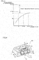
- Weight reduction in the outboard motor unit 1 is now described with reference to Fig. 3 .
- the amount of air to be generated from the supercharger in order to demonstrate the desired engine performance at a predetermined supercharging pressure be Q.
- the weight of one supercharger that generates the amount of air Q be Wa.
- the weight of the supercharger increases.
- the degree of increase in the weight of the supercharger decreases as the amount of air increases. That is, the weight of the supercharger logarithmically increases.
- the outboard motor unit 1 includes the air passage 40 through which the air compressed by the supercharger 16 of the outboard motor 10 is supplied to the engine 21 of the outboard motor 20.
- the compressed air is supplied from the supercharger 16 of the outboard motor 10 to the engine 21 of the outboard motor 20 without providing the supercharger 16 in the outboard motor 20, and hence the outboard motor 20 is reduced in size and weight as compared with the case where the supercharger 16 is provided in the outboard motor 20. Consequently, an increase in the size and weight of the outboard motor unit 1 including the outboard motor 10 and the outboard motor 20 is significantly reduced or prevented while the compressed air is supplied to both the engine 11 of the outboard motor 10 and the engine 21 of the outboard motor 20,
- the intercooler 14b that cools the air compressed by the supercharger 16 is provided downstream of the supercharger 16, and the air compressed and cooled by the supercharger 16 and the intercooler 14b is supplied to the engine 11 of the outboard motor 10 and the engine 21 of the outboard motor 20.
- the compressed air is cooled by the intercooler 14b such that the density of the compressed air to be introduced into the engine 11 and the engine 21 is increased, and hence the drive force (engine performance) of the engine 11 and the engine 21 is increased.
- the intercooler 14b is shared by the outboard motors 10 and 20, and hence an increase in the size and weight of the outboard motor unit 1 is further significantly reduced or prevented.
- the outboard motor unit 1 includes the ECU 13 and the bypass valves 18a and 18b that distribute the air compressed by the supercharger 16 of the outboard motor 10 to the engine 11 and the engine 21.
- the ECU 13 and the bypass valves 18a and 18b that distribute the air compressed by the supercharger 16 of the outboard motor 10 to the engine 11 and the engine 21.
- bypass valves 18a and 18b that adjust the amount of compressed air that flows through the air passage 40 and the ECU 13 that adjusts the opening degree of the bypass valves 18a and 18b are provided.
- the drive force of the outboard motor 10 and the drive force of the outboard motor 20 are more appropriately controlled by the bypass valves 18a and 18b and the ECU 13.
- the opening degree of the bypass valves 18a and 18b is adjusted by the ECU 13 that is provided in the outboard motor 10 and controls the driving of the engine 11.
- the ECU 13 that controls the driving of the engine 11 is used as (diverted to) an opening degree adjuster that adjusts the opening degree of the bypass valves 18a and 18b such that the number of components in the outboard motor unit 1 is reduced as compared with the case where the opening degree adjuster is provided separately from the ECU 13 that controls the driving of the engine 11.
- the ECU 13 adjusts the opening degree of the bypass valves 18a and 18b based on the operating condition of the engine 11 and the operating condition of the engine 21 transmitted from the ECU 23.
- an appropriate amount of air is supplied to the engine 11 and the engine 21 to correspond to the operating condition of the engine 11 and the operating condition of the engine 21, respectively. Consequently, the drive force of the outboard motor 10 and the drive force of the outboard motor 20 are more appropriately controlled.
- the air compressed by the supercharger 16 of the outboard motor 10 is supplied not only to the engine 21 of the outboard motor 20 but also to the engine 31 of the outboard motor 30 through the air passage 40.
- the compressed air is supplied from the supercharger 16 of the outboard motor 10 to the engine 21 of the outboard motor 20 and the engine 31 of the outboard motor 30 without providing the supercharger 16 in the outboard motors 20 and 30, and hence the outboard motors 20 and 30 are reduced in size and weight as compared with the case where the supercharger 16 is provided in the outboard motors 20 and 30.
- the outboard motor 10 is sandwiched between the outboard motors 20 and 30 such that the compressed air is easily distributed to the outboard motor 20 and the outboard motor 30 through the air passage 40.
- the outboard motor 10 includes the main passage 15a through which the air compressed by the supercharger 16 is supplied to the engine 11 and the branch passage 41 connected to the portion downstream of the supercharger 16 in the main passage 15a as the air passage 40.
- the branch passage 41 connected to the portion downstream of the supercharger 16 in the main passage 15a as the air passage 40.
- the air compressed and cooled by the supercharger 16 and the intercooler 14b is supplied from the outboard motor 10 to the engine 11 of the outboard motor 10 and the engine 21 of the outboard motor 20.
- the intercooler 14b that cools the air compressed by the supercharger 16 is provided in the outboard motor 10 such that the density of the compressed air to be supplied to the engine 11 and the engine 21 is increased. Consequently, the drive force (engine performance) of the engine 11 and the engine 21 is increased.
- the bypass valve 18a that adjusts the amount of compressed air that flows through the air passage 40 by adjusting flow of air in the bypass passage 15b is provided on the bypass passage 15b. Furthermore, the ECU 13 that adjusts the opening degree of the bypass valve 18a is provided in the outboard motor unit 1. Thus, the opening degree of the bypass valve 18a provided on the bypass passage 15b is adjusted such that the drive force of the outboard motor 10 is appropriately controlled. In addition, the bypass valve 18a is opened to allow excessively compressed air to escape through the bypass passage 15b. Thus, supply of the excessively compressed air to the engine 11 is significantly reduced or prevented.
- both the bypass passage 15b and the bypass valve 18a are provided inside the cowling 12 of the outboard motor 10.
- the bypass passage 15b is located in the vicinity of the supercharger 16, and hence the bypass passage 15b is easily shortened.
- the opening degree of the bypass valve 18b that is provided on the bypass passage 15c and adjusts the amount of compressed air that flows through the air passage 40 by adjusting flow of air in the bypass passage 15c is adjusted by the ECU 13.
- the opening degree of the bypass valve 18a provided on the bypass passage 15b the opening degree of the bypass valve 18b provided on the bypass passage 15c is adjusted such that not only the drive force of the outboard motor 10 but also the drive force of the outboard motor 20 is appropriately controlled.
- the bypass valve 18b is opened to allow excessively compressed air to escape through the bypass passage 15c.
- supply of the excessively compressed air to the engine 21 is significantly reduced or prevented.
- the ECU 13 adjusts the opening degree of the bypass valve 18a and the opening degree of the bypass valve 18b based on the operating condition of the engine 11 and the operating condition of the engine 21 transmitted from the ECU 23.
- the opening degree of the bypass valve 18a and the opening degree of the bypass valve 18b are adjusted to correspond to the operating condition of the engine 11 and the operating condition of the engine 21 such that an appropriate amount of air is supplied to each of the engine 11 and the engine 21. Consequently, the drive force of the outboard motor 10 and the drive force of the outboard motor 20 are more appropriately controlled.
- the check valve 17a that prevents backflow of the compressed air is provided on the main passage 15a upstream of the connection position C2 between the main passage 15a and the bypass passage 15b and downstream of the connection position C1 between the branch passage 41 and the main passage 15a.
- backflow of the compressed air is prevented by the check valve 17a such that the amount of air to be supplied to the engine 11 of the compressed air that has passed through the check valve 17a is reliably controlled by the bypass valve 18a.
- the check valve 17b that prevents backflow of the compressed air is provided on the branch passage 41 upstream of the connection position C3 between the branch passage 41 and the bypass passage 15c and downstream of the connection position C1 between the branch passage 41 and the main passage 15a.
- backflow of the compressed air is prevented by the check valve 17b such that the amount of air to be supplied to the engine 21 of the compressed air that has passed through the check valve 17b is reliably controlled by the bypass valve 18b.
- both the check valve 17a and the check valve 17b are provided inside the cowling 12 of the outboard motor 10.
- the check valve 17a and the check valve 17b are located in the vicinity of the connection position C1 between the branch passage 41 and the main passage 15a, and hence the main passage 15a and the branch passage 41 are easily shortened.
- both the bypass passage 15c and the bypass valve 18b are provided inside the cowling 12 of the outboard motor 10.
- the bypass passage 15c is located in the vicinity of the supercharger 16, and hence the bypass passage 15c is easily shortened.
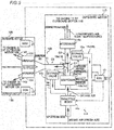
- a marine vessel 200 including an outboard motor unit 101 according to a second preferred embodiment is now described with reference to Figs. 4 and 5 .
- intercoolers 124 and 134 are respectively provided in outboard motors 120 and 130 including no supercharger, different than the outboard motor unit 1 according to the first preferred embodiment.
- the same structures as those of the first preferred embodiment are denoted by the same reference numerals, to omit the description.
- communication is indicated by two-dot chain lines.
- the marine vessel 200 includes the outboard motor unit 101 including a plurality of (three) outboard motors 110, 120, and 130.
- the outboard motors 110, 120, and 130 are examples of a "first outboard motor”, a “second outboard motor”, and a “third outboard motor”, respectively.
- the outboard motor unit 101 includes the outboard motors 110, 120, and 130 and an air passage 140.
- An air intake 114 of the outboard motor 110 includes a supercharger 16 and an intercooler 114b located inside a cowling 12.
- the outboard motor 120 includes the intercooler 124 that is located inside a cowling 22 and cools compressed air supplied from the supercharger 16.
- the outboard motor 130 includes the intercooler 134 that is located inside a cowling 32 and cools compressed air supplied from the supercharger 16.
- the intercooler 114b is an example of a "cooler” or a "first cooler”
- the intercooler 124 is an example of a "cooler" or a "second cooler”.
- the air passage 140 includes a branch passage 41 that passes through the cowling 12 of the outboard motor 10 and re-branch passages 142 and 143 that pass through the cowling 22 of the outboard motor 120 and the cowling 32 of the outboard motor 130, respectively.
- the branch passage 41 branches into two such that the re-branch passages 142 and 143 are formed.
- the intercooler 114b is located downstream of a connection position C2 between a main passage 15a and a bypass passage 15b in the main passage 15a (downstream of the supercharger 16).
- the intercooler 124 is located on the re-branch passage 142 inside the cowling 22.
- the intercooler 134 is located on the re-branch passage 143 inside the cowling 32.
- the compressed air after the distribution (high-temperature compressed air) is cooled by the intercoolers 114b, 124, and 134 provided in the outboard motors 110, 120, and 130, and then is supplied to the engines 11, 21 and 31, respectively.
- the remaining structures of the second preferred embodiment are similar to those of the first preferred embodiment.
- the outboard motor unit 101 includes the air passage 140 through which the air compressed by the supercharger 16 of the outboard motor 110 is supplied to the engine 21 of the outboard motor 120.
- an increase in the size and weight of the outboard motor unit 101 including the outboard motor 110 and the outboard motor 120 is significantly reduced or prevented while the compressed air is supplied to both the engine 11 of the outboard motor 110 and the engine 21 of the outboard motor 120.
- the intercooler 114b that is provided downstream of the supercharger 16 inside the cowling 12 and cools the air compressed by the supercharger 16 and the intercooler 124 that is provided inside the cowling 22 and cools the compressed air supplied from the supercharger 16 of the outboard motor 110 are provided in the outboard motor unit 101.
- the compressed air to be supplied to the engines 11 and 21 is sufficiently cooled by the intercooler 114b and the intercooler 124 without increasing the size of the intercooler 114b to sufficiently cool the compressed air.
- the intercooler 124 is provided inside the cowling 22 in which the engine 21 is located such that the air cooled by the intercooler 124 is promptly supplied to the engine 21, and hence warming of the cooled air due to the surrounding environment or the like is significantly reduced or prevented. Consequently, the density of the air to be supplied to the engine 21 is reliably increased.
- the remaining advantageous effects of the second preferred embodiment are similar to those of the first preferred embodiment.
- outboard motor unit 1 (101) preferably includes one outboard motor 10 (110) (first outboard motor) including the supercharger 16 and the two outboard motors 20 and 30 (120 and 130) (second and third outboard motors) including no supercharger in each of the first and second preferred embodiments described above, the present invention is not restricted to this. It is only required that the outboard motor unit include at least one first outboard motor including the supercharger and at least one second outboard motor including no supercharger.
- an outboard motor unit 201 may include two outboard motors 210a and 210b each including both a supercharger 16 and an intercooler 14b located inside a cowling 12 and two outboard motors 220a and 220b each including no supercharger or intercooler.
- the outboard motors 210a and 210b are examples of a "first outboard motor”
- the outboard motors 220a and 220b are examples of a "second outboard motor”.
- the outboard motor 220a is located on the port side with respect to the outboard motors 210a and 210b and the outboard motor 220b is located on the starboard side with respect to the outboard motors 210a and 210b to sandwich the outboard motors 210a and 210b therebetween.
- the outboard motor unit 201 further includes an air passage 240a through which air compressed by the supercharger 16 of the outboard motor 210a is supplied to an engine 21 of the outboard motor 220a and an air passage 240b through which air compressed by the supercharger 16 of the outboard motor 210b is supplied to an engine 21 of the outboard motor 220b.
- an outboard motor unit 301 may include one outboard motor 310 including both a supercharger 16 and an intercooler 14b located inside a cowling 12 and four outboard motors 320a, 320b, 320c, and 320d including no supercharger or intercooler.
- the outboard motor 310 is an example of a "first outboard motor”
- the outboard motors 320a, 320b, 320c, and 320d are examples of a "second outboard motor”.
- the outboard motors 320a and 320b are located on the port side with respect to the outboard motor 310 and the outboard motors 320c and 320d are located on the starboard side with respect to the outboard motor 310 to sandwich the outboard motor 310 therebetween.
- the outboard motor unit 301 further includes an air passage 340 through which air compressed by the supercharger 16 of the outboard motor 310 is supplied to engines 21 of the outboard motors 320a to 320d,
- bypass valves 18a and 18b first and second regulator valves
- present invention is not restricted to this.
- the amount of air that flows through the main passage and the branch passage may alternatively be adjusted by valve members other than the bypass valves, members or mechanisms other than the valve members, or the like.
- check valves 17a and 17b are preferably used in each of the first and second preferred embodiments described above, the present invention is not restricted to this.
- the first check valve and the second check valve may not be used.
- a main passage side bypass system including the bypass valve 18a and the bypass passage 15b and a branch passage side bypass system including the bypass valve 18b and the bypass passage 15c are integrated into one of the bypass systems.
- outboard motor 20 (120) (second outboard motor) and the outboard motor 30 (130) (third outboard motor) including no supercharger preferably sandwich the outboard motor 10 (110) (first outboard motor) including the supercharger 16 in each of the first and second preferred embodiments described above, the present invention is not restricted to this.
- the first outboard motor may not be sandwiched between the second outboard motor and the third outboard motor.
- the present invention is not restricted to this.
- the outboard motor unit may alternatively include both a second outboard motor including no supercharger or intercooler and a second outboard motor including no supercharger but including an intercooler.
- the marine vessel 100 (200) preferably includes the outboard motor unit 1 (101) that includes the outboard motor 10 (110) including the supercharger 16 and the two outboard motors 20 (120) (second outboard motor) and 30 (130) (third outboard motor) including no supercharger in each of the first and second preferred embodiments described above, the present invention is not restricted to this.
- the marine vessel may alternatively include an outboard motor not included in an outboard motor unit.
- the marine vessel may include an outboard motor that includes a supercharger and supplies no compressed air to other outboard motors, or may include an outboard motor including no supercharger, to which no compressed air is supplied from other outboard motors.
Landscapes
- Engineering & Computer Science (AREA)
- Chemical & Material Sciences (AREA)
- Combustion & Propulsion (AREA)
- Mechanical Engineering (AREA)
- General Engineering & Computer Science (AREA)
- Ocean & Marine Engineering (AREA)
- Physics & Mathematics (AREA)
- Thermal Sciences (AREA)
- Supercharger (AREA)
- Output Control And Ontrol Of Special Type Engine (AREA)
Abstract
Description
- The present invention relates to an outboard motor unit including an outboard motor that includes a supercharger and a marine vessel including the outboard motor unit.
- An outboard motor including a supercharger is known in general. Such an outboard motor is disclosed in Japanese Patent Laid-Open No.
2011-226390 - Japanese Patent Laid-Open No.
2011-226390 2011-226390 - When a plurality of outboard motors each including the supercharger described in Japanese Patent Laid-Open No.
2011-226390 - It is an object of the present invention to provide an outboard motor unit including a plurality of outboard motors, in which an increase in its size and weight is significantly reduced or prevented while air is supplied to engines of the plurality of outboard motors and a marine vessel including the outboard motor unit. According to the present invention said object is solved by an outboard motor unit having the features of the independent claim 1. Preferred embodiments are laid down in the dependent claims.
- An outboard motor unit according to a preferred embodiment includes a first outboard motor including a first cowling, a first engine housed in the first cowling, and a supercharger that is provided inside the first cowling and is configured to supply compressed air to the first engine, a second outboard motor including a second cowling and a second engine housed in the second cowling, and an air passage through which the air compressed by the supercharger of the first outboard motor is supplied to the second engine of the second outboard motor.
- An outboard motor unit according to a preferred embodiment includes the air passage through which the air compressed by the supercharger of the first outboard motor is supplied to the second engine of the second outboard motor. Thus, the compressed air is supplied from the supercharger of the first outboard motor to the second engine of the second outboard motor without providing the supercharger in the second outboard motor, and hence the second outboard motor is reduced in size and weight as compared with the case where the supercharger is provided In the second outboard motor. Consequently, an increase in the size and weight of the outboard motor unit including the first outboard motor and the second outboard motor is significantly reduced or prevented while the compressed air is supplied to both the first engine of the first outboard motor and the second engine of the second outboard motor.
- An outboard motor unit according to a preferred embodiment preferably further includes a cooler that is provided downstream of the supercharger and is configured to cool the air compressed by the supercharger, and the air compressed and cooled by the supercharger and the cooler is preferably supplied to the first engine of the first outboard motor and the second engine of the second outboard motor. Accordingly, the compressed air is cooled by the cooler such that the density of the compressed air to be introduced into the first engine and the second engine is increased, and hence the drive force (engine performance) of the first engine and the second engine is increased. In addition, when the cooler is shared by the first and second outboard motors, an increase in the size and weight of the outboard motor unit is further significantly reduced or prevented.
- An outboard motor unit according to a preferred embodiment preferably further includes an air amount adjuster that is configured to distribute the air compressed by the supercharger of the first outboard motor to the first engine and the second engine. Accordingly, an appropriate amount of air is supplied to the first engine and the second engine by the air amount adjuster. Consequently, the drive force of the first outboard motor and the drive force of the second outboard motor are appropriately controlled.
- In this case, the air amount adjuster preferably includes a regulator valve that is configured to adjust an amount of the compressed air that is configured to flow through the air passage and an opening degree adjuster that is configured to adjust an opening degree of the regulator valve. Accordingly, the drive force of the first outboard motor and the drive force of the second outboard motor are more appropriately controlled by the regulator valve and the opening degree adjuster.
- In the structure in which the air amount adjuster includes the regulator valve and the opening degree adjuster, the opening degree adjuster preferably includes a first controller provided in the first outboard motor and configured or programmed to control driving of the first engine. Accordingly, the first controller that controls the driving of the first engine is used as (diverted to) the opening degree adjuster that adjusts the opening degree of the regulator valve such that the number of components in the outboard motor unit is reduced as compared with the case where the opening degree adjuster is provided separately from the first controller that controls the driving of the first engine.
- In the structure in which the opening degree adjuster includes the first controller, the second outboard motor preferably further includes a second controller configured or programmed to communicate with the first controller and to control driving of the second engine, and the first controller is preferably configured or programmed to adjust the opening degree of the regulator valve based on an operating condition of the first engine and an operating condition of the second engine transmitted from the second controller. Accordingly, an appropriate amount of air is supplied to the first engine and the second engine to correspond to the operating condition of the first engine and the operating condition of the second engine, respectively. Consequently, the drive force of the first outboard motor and the drive force of the second outboard motor are more appropriately controlled.
- An outboard motor unit according to a preferred embodiment preferably further includes a third outboard motor including a third cowling and a third engine housed in the third cowling, and the air compressed by the supercharger of the first outboard motor is preferably supplied not only to the second engine of the second outboard motor but also to the third engine of the third outboard motor through the air passage. Accordingly, the compressed air is supplied from the supercharger of the first outboard motor to the second engine of the second outboard motor and the third engine of the third outboard motor without providing the supercharger in the second and third outboard motors, and hence the second and third outboard motors are reduced in size and weight as compared with the case where the supercharger is provided in the second and third outboard motors. Consequently, an increase in the size and weight of the outboard motor unit including the first, second, and third outboard motors is significantly reduced or prevented while the compressed air is supplied to each of the first engine of the first outboard motor, the second engine of the second outboard motor, and the third engine of the third outboard motor.
- In this case, the first outboard motor is preferably sandwiched between the second outboard motor and the third outboard motor. Accordingly, the compressed air is easily distributed to the second outboard motor and the third outboard motor through the air passage.
- In an outboard motor unit according to a preferred embodiment, the first outboard motor preferably further includes a main passage through which the air compressed by the supercharger is supplied to the first engine, and the air passage preferably includes a branch passage connected to a portion downstream of the supercharger in the main passage. Accordingly, the compressed air that flows through the main passage is easily supplied to the second engine of the second outboard motor through the branch passage.
- In this case, an outboard motor unit according to a preferred embodiment preferably further includes a cooler that is provided upstream of a connection position between the branch passage and the main passage and downstream of the supercharger in the main passage inside the first cowling and is configured to cool the air compressed by the supercharger, and the air compressed and cooled by the supercharger and the cooler is preferably supplied from the first outboard motor to the first engine of the first outboard motor and the second engine of the second outboard motor. Accordingly, it is not necessary to provide the cooler in the second outboard motor, and hence the second outboard motor is further reduced in size and weight. Consequently, an increase in the size and weight of the outboard motor unit is further significantly reduced or prevented. Furthermore, the cooler that cools the air compressed by the supercharger is provided in the first outboard motor such that the density of the compressed air to be supplied to the first engine and the second engine is increased. Consequently, the drive force (engine performance) of the first engine and the second engine is increased.
- In the structure in which the opening degree adjuster includes the first controller, an outboard motor unit according to a preferred embodiment preferably further includes an air amount adjuster that is configured to distribute the air compressed by the supercharger of the first outboard motor to the first engine and the second engine and a first bypass passage that is configured to connect a portion downstream of the cooler in the main passage to a portion upstream of the supercharger in the main passage and is configured to return the air compressed by the supercharger to the supercharger, and the air amount adjuster preferably includes a first regulator valve that is provided on the first bypass passage and is configured to adjust an amount of the compressed air that flows through the air passage by adjusting flow of the air in the first bypass passage and an opening degree adjuster that is configured to adjust an opening degree of the first regulator valve. Accordingly, the opening degree of the first regulator valve provided on the first bypass passage is adjusted such that the drive force of the first outboard motor is appropriately controlled. In addition, the first regulator valve is opened to allow excessively compressed air to escape through the first bypass passage. Thus, supply of the excessively compressed air to the first engine is significantly reduced or prevented.
- In the structure including the first bypass passage and the first regulator valve, both the first bypass passage and the first regulator valve are preferably provided inside the first cowling of the first outboard motor. Accordingly, the first bypass passage is located in the vicinity of the supercharger, and hence the first bypass passage is easily shortened.
- In the structure including the first bypass passage and the first regulator valve, an outboard motor unit according to a preferred embodiment preferably further includes a second bypass passage that is configured to connect the branch passage to the portion upstream of the supercharger in the main passage and is configured to return the air compressed by the supercharger to the supercharger, the air amount adjuster preferably includes a second regulator valve that is provided on the second bypass passage and that is configured to adjust the amount of the compressed air that flows through the air passage by adjusting flow of the air in the second bypass passage, and an opening degree of the second regulator valve is preferably adjusted by the opening degree adjuster. Accordingly, in addition to the opening degree of the first regulator valve provided on the first bypass passage, the opening degree of the second regulator valve provided on the second bypass passage is adjusted such that not only the drive force of the first outboard motor but also the drive force of the second outboard motor is appropriately controlled. Furthermore, the second regulator valve is opened to allow excessively compressed air to escape through the second bypass passage. Thus, supply of the excessively compressed air to the second engine is significantly reduced or prevented.
- In the structure in which the second outboard motor includes the second bypass passage and the second regulator valve, the opening degree adjuster preferably includes a first controller provided in the first outboard motor and configured or programmed to control driving of the first engine, the second outboard motor preferably further includes a second controller configured or programmed to communicate with the first controller and to control driving of the second engine, and the first controller is preferably configured or programmed to adjust the opening degree of the first regulator valve and the opening degree of the second regulator valve based on an operating condition of the first engine and an operating condition of the second engine transmitted from the second controller. Accordingly, the opening degree of the first regulator valve and the opening degree of the second regulator valve are adjusted to correspond to the operating condition of the first engine and the operating condition of the second engine such that an appropriate amount of air is supplied to each of the first engine and the second engine. Consequently, the drive force of the first outboard motor and the drive force of the second outboard motor are more appropriately controlled.
- In the structure in which the second outboard motor includes the second bypass passage and the second regulator valve, an outboard motor unit according to a preferred embodiment preferably further includes a first check valve that is located upstream of a connection position between the main passage and the first bypass passage and downstream of the connection position between the branch passage and the main passage in the main passage and prevents backflow of the compressed air, and a second check valve that is located upstream of a connection position between the branch passage and the second bypass passage and downstream of the connection position between the branch passage and the main passage in the branch passage and prevents backflow of the compressed air. Accordingly, backflow of the compressed air is prevented by the first check valve such that the amount of air to be supplied to the first engine of the compressed air that has passed through the first check valve is reliably controlled by the first regulator valve. Similarly, backflow of the compressed air is prevented by the second check valve such that the amount of air to be supplied to the second engine of the compressed air that has passed through the second check valve is reliably controlled by the second regulator valve.
- The above and other elements, features, steps, characteristics and advantages of preferred embodiments will become more apparent from the following detailed description of the preferred embodiments with reference to the attached drawings.
-
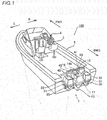
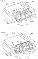
Fig. 1 is a perspective view schematically showing a marine vessel including an outboard motor unit according to a first preferred embodiment. -
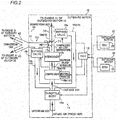
Fig. 2 is a diagram schematically showing the outboard motor unit according to the first preferred embodiment. -
Fig. 3 is a graph for illustrating the relationship between the amount of air and the weight of a supercharger in the outboard motor unit according to the first preferred embodiment. -
Fig. 4 is a perspective view schematically showing a portion of a marine vessel including an outboard motor unit according to a second preferred embodiment. -
Fig. 5 is a diagram schematically showing the outboard motor unit according to the second preferred embodiment. -
Fig. 6 is a perspective view schematically showing a portion of a marine vessel including an outboard motor unit according to a first modification of the first preferred embodiment. -
Fig. 7 is a perspective view schematically showing a portion of a marine vessel including an outboard motor unit according to a second modification of the first preferred embodiment. - Preferred embodiments are hereinafter described with reference to the drawings.
- The structure of a
marine vessel 100 including an outboard motor unit 1 according to a first preferred embodiment is now described with reference toFigs. 1 and2 . In the figures, arrow FWD represents the forward movement direction of themarine vessel 100, and arrow BWD represents the backward movement direction of themarine vessel 100. In the figures, arrow R represents the starboard direction of themarine vessel 100, and arrow L represents the portside direction of themarine vessel 100. - As shown in
Fig. 1 , themarine vessel 100 includes an outboard motor unit 1 including a plurality of (three)outboard motors vessel body 2, asteering wheel 3, and a remote controller 4. In other words, themarine vessel 100 is a marine vessel including the plurality of outboard motors. Theoutboard motors - The
steering wheel 3 steers the vessel body 2 (turns theoutboard motors steering wheel 3 is connected to each of steerings (not shown) of theoutboard motors outboard motors steering wheel 3. - The remote controller 4 manipulates the shifts and outputs (throttle opening degrees) of the
outboard motors outboard motors outboard motors - As described above, the outboard motor unit 1 includes the
outboard motors air passage 40. Theoutboard motors vessel body 2. In the outboard motor unit 1, theoutboard motors outboard motor 10, respectively, to sandwich theoutboard motor 10 therebetween. Theair passage 40 includes a pipe member that connects theoutboard motor 10 to theoutboard motors air passage 40. - The
outboard motor 10 includes anengine 11, acowling 12 in which theengine 11 is housed, and an ECU (engine control unit) 13 and anair intake 14 located inside thecowling 12. Theengine 11 is an internal combustion engine that generates a thrust force for moving themarine vessel 100 by rotationally driving a propeller (not shown) by burning an air-fuel mixture in which air (intake air) and fuel are mixed. TheECU 13 controls not only theengine 11 but also the entireoutboard motor 10. Theair intake 14 supplies air to theengine 11. Theengine 11 and thecowling 12 are examples of a "first engine" and a "first cowling", respectively, and theECU 13 is an example of an "air amount adjuster", an "opening degree adjuster", or a "first controller". - The
outboard motor 20 includes anengine 21, acowling 22 in which theengine 21 is housed, and anECU 23 located inside thecowling 22. Similarly, theoutboard motor 30 includes anengine 31, acowling 32 in which theengine 31 is housed, and anECU 33 located inside thecowling 32. Theengines marine vessel 100 by rotationally driving propellers (not shown) by burning an air-fuel mixture in which air (intake air) and fuel are mixed. Theengines cowlings ECU 23 is an example of a "second controller". - The
ECU 23 controls not only theengine 21 but also the entireoutboard motor 20. Similarly, theECU 33 controls not only theengine 31 but also the entireoutboard motor 30. TheECUs ECU 13 of theoutboard motor 10. As a communication method, wired communication or wireless communication may be used. Thus, theECU 13 grasps the operating conditions of theengines ECUs Fig. 2 , the communication is indicated by two-dot chain lines. - The
outboard motor 10 includes asupercharger 16 and anintercooler 14b such that theoutboard motor 10 is larger in size and weight than theoutboard motors - The
air passage 40 includes abranch passage 41 that passes through thecowling 12 of theoutboard motor 10 andre-branch passages branch passage 41. A portion of theair passage 40 is located outside theoutboard motors outboard motors outboard motors air passage 40 is flexibly deformed along with the rotation. Consequently, leakage of air from the pipe member that theair passage 40 includes due to the rotation of theoutboard motors - According to the first preferred embodiment, compressed and cooled air is supplied from the
outboard motor 10 to theengine 21 of theoutboard motor 20 and theengine 31 of theoutboard motor 30. Specifically, the air compressed by thesupercharger 16 of theair intake 14 of theoutboard motor 10 and cooled by theintercooler 14b is supplied from theoutboard motor 10 to theengine 21 of theoutboard motor 20 and theengine 31 of theoutboard motor 30 through theair passage 40. That is, theintercooler 14b is shared by theoutboard motors air intake 14 is described in detail below. - As shown in
Fig. 2 , theair intake 14 includes anair passage 15 through which air (intake air) flows and athrottle body 14a, thesupercharger 16, and theintercooler 14b located on theair passage 15. Theair passage 15 includes amain passage 15a, thebranch passage 41 that branches from themain passage 15a, and twobypass passages intercooler 14b is an example of a "cooler". Thebypass passages - Air (intake air) is introduced into the
main passage 15a through an air cleaner (not shown). The air introduced into themain passage 15a is supplied to theengine 11 through themain passage 15a. In themain passage 15a, thethrottle body 14a, thesupercharger 16, and theintercooler 14b are located in this order from the upstream side to the downstream side. Thethrottle body 14a adjusts the amount (air amount) of air (intake air) to be supplied to thesupercharger 16 by adjusting the amount of air to be introduced. - The
supercharger 16 includes a so-calledmechanical compressor 16a that compresses air and adrive force transmitter 16b that transmits a drive force for driving thecompressor 16a. Thecompressor 16a may be of a centrifugal type, Roots type, screw type, rotary type, or the like. - The
drive force transmitter 16b acquires a drive force from theengine 11 of theoutboard motor 10. Thedrive force transmitter 16b may transmit a drive force from a drive source other than theengine 11, such as an electric motor, to thecompressor 16a. In this case, thedrive force transmitter 16b drives thecompressor 16a with a drive force obtained by adjusting the magnitude of the drive force from the drive source based on the control by theECU 13. - The
intercooler 14b cools the air (high-temperature compressed air) compressed by thesupercharger 16 using water. Specifically, in theintercooler 14b, heat exchange is performed between the high-temperature compressed air that flows through theintercooler 14b and the water pumped up by a pump (not shown) through a heat radiating member such as a fin. Consequently, in theintercooler 14b, the high-temperature compressed air is cooled. That is, theintercooler 14b is water-cooled. The temperature of the air to be supplied to theengine 11 of theoutboard motor 10, theengine 21 of theoutboard motor 20, and theengine 31 of theoutboard motor 30 is lowered by theintercooler 14b such that the density of the air is sufficiently increased. - A portion of the compressed and cooled air (low-temperature compressed air) that flows through the
main passage 15a is supplied (distributed) to theoutboard motors branch passage 41. A first end of thebranch passage 41 is connected to themain passage 15a at a connection position C1 downstream of theintercooler 14b. A second end of thebranch passage 41 branches into the twore-branch passages branch passage 41 is connected to themain passage 15a inside thecowling 12, and the second end of thebranch passage 41 is connected to there-branch passages cowling - The compressed and cooled air that flows through the
main passage 15a is returned to thesupercharger 16 through thebypass passage 15b. A first end of thebypass passage 15b is connected to themain passage 15a at a connection position C2 downstream of the connection position C1 between thebranch passage 41 and themain passage 15a (downstream of theintercooler 14b). A second end of thebypass passage 15b is connected to a portion upstream of thesupercharger 16 in themain passage 15a. Thebypass passage 15b is located inside thecowling 12. - The compressed and cooled air that flows through the
branch passage 41 is returned to thesupercharger 16 through thebypass passage 15c. A first end of thebypass passage 15c is connected to thebranch passage 41 at a connection position C3 downstream of the connection position C1 (downstream of theintercooler 14b). A second end of thebypass passage 15c is connected to the portion upstream of thesupercharger 16 in themain passage 15a. Thebypass passage 15c is located inside thecowling 12. - The
main passage 15a and thebranch passage 41 includecheck valves check valve 17a is located on themain passage 15a downstream of the connection position C1 and upstream of the connection position C2. Thecheck valve 17b is located on thebranch passage 41 downstream of the connection position C1 and upstream of the connection position C3. Both thecheck valves check valve 17a and thecheck valve 17b are examples of a "first check valve" and a "second check valve", respectively. - According to the first preferred embodiment,
bypass valves bypass passages bypass valve 18a adjusts the amount of compressed and cooled air to be supplied to theengine 11 of theoutboard motor 10 through themain passage 15a by adjusting the amount of air that flows through thebypass passage 15b. Thebypass valve 18b adjusts the amount of compressed and cooled air to be supplied to theengine 21 of theoutboard motor 20 and theengine 31 of theoutboard motor 30 through thebranch passage 41 by adjusting the amount of air that flows through thebypass passage 15c. Thebypass valve 18a is an example of an "air amount adjuster", a "regulator valve", or a "first regulator valve", and thebypass valve 18b is an example of an "air amount adjuster", a "regulator valve", or a "second regulator valve". - The compressed and cooled air that flows through a portion downstream of the connection position C3 in the
branch passage 41 is supplied (distributed) to theengine 21 of theoutboard motor 20 and theengine 31 of theoutboard motor 30 through there-branch passages re-branch passage 42 and a first end of there-branch passage 43 are connected to thebranch passage 41 outside theoutboard motors re-branch passage 42 is connected to theengine 21 inside thecowling 22. A second end of there-branch passage 43 is connected to theengine 31 inside thecowling 32. - Consequently, in the outboard motor unit 1, the opening degree of the
throttle body 14a is adjusted by theECU 13 such that the amount of air to be introduced into themain passage 15a is adjusted. The air introduced into themain passage 15a and the air introduced into thebranch passage 41 are compressed and cooled by thesupercharger 16 and theintercooler 14b. - In the outboard motor unit 1, the opening degree of the
bypass valve 18a and the opening degree of thebypass valve 18b are adjusted by theECU 13 such that the low-temperature compressed air is distributed to theengines bypass valve 18a and the opening degree of thebypass valve 18b are adjusted by theECU 13 such that the amount of low-temperature compressed air that flows through a portion downstream of the connection position C1 in themain passage 15a and the amount of low-temperature compressed air that flows through thebranch passage 41 are adjusted. Furthermore, the opening degree of thebypass valve 18a and the opening degree of thebypass valve 18b are adjusted by theECU 13 such that the amount of low-temperature compressed air that flows through a portion downstream of the connection position C2 in themain passage 15a and the amount of low-temperature compressed air that flows through the portion downstream of the connection position C3 in thebranch passage 41 are adjusted. Consequently, the opening degree of thebypass valve 18a and the opening degree of thebypass valve 18b are adjusted by theECU 13 such that the amount of low-temperature compressed air that flows through theair passage 40 is adjusted. - The opening degree of the
throttle body 14a, the opening degree of thebypass valve 18a, and the opening degree of thebypass valve 18b are controlled by theECU 13 based on the operating conditions of theengines ECU 13 grasps the operating condition of each of theengines engine 21 and the operating condition of theengine 31 transmitted from theECUs - The low-temperature compressed air that flows through the portion downstream of the connection position C2 in the
main passage 15a is supplied to theengine 11 of theoutboard motor 10. The low-temperature compressed air that flows through the portion downstream of the connection position C3 in thebranch passage 41 is supplied to theengine 21 of theoutboard motor 20 and theengine 31 of theoutboard motor 30 through there-branch passages engine 11, which is required to drive thesupercharger 16, is preferably larger than the amount of compressed air to be supplied to theengines - Weight reduction in the outboard motor unit 1 is now described with reference to
Fig. 3 . In each of the three engines of the three outboard motors, let the amount of air to be generated from the supercharger in order to demonstrate the desired engine performance at a predetermined supercharging pressure be Q. Let the weight of one supercharger that generates the amount of air Q be Wa. - In general, when the amount of air that corresponds to the predetermined supercharging pressure increases, the weight of the supercharger increases. However, the degree of increase in the weight of the supercharger decreases as the amount of air increases. That is, the weight of the supercharger logarithmically increases. Therefore, as compared with the total weight (= 3 x Wa) of the superchargers in the case where the supercharger that generates the amount of air Q is provided in each of the three outboard motors, as in the first preferred embodiment, the supercharger that generates the amount of air (3 x Q) (the supercharger that generates the amount of air that three superchargers generate) is provided in only one of the three outboard motors but no supercharger is provided in the remaining two outboard motors such that the total weight (= W) of the supercharger is reduced, as shown in
Fig. 3 . Consequently, the weight of the entire outboard motor unit 1 is reduced to reduce the weight of themarine vessel 100. - According to the first preferred embodiment, the following advantageous effects are obtained.
- According to the first preferred embodiment, the outboard motor unit 1 includes the
air passage 40 through which the air compressed by thesupercharger 16 of theoutboard motor 10 is supplied to theengine 21 of theoutboard motor 20. Thus, the compressed air is supplied from thesupercharger 16 of theoutboard motor 10 to theengine 21 of theoutboard motor 20 without providing thesupercharger 16 in theoutboard motor 20, and hence theoutboard motor 20 is reduced in size and weight as compared with the case where thesupercharger 16 is provided in theoutboard motor 20. Consequently, an increase in the size and weight of the outboard motor unit 1 including theoutboard motor 10 and theoutboard motor 20 is significantly reduced or prevented while the compressed air is supplied to both theengine 11 of theoutboard motor 10 and theengine 21 of theoutboard motor 20, - According to the first preferred embodiment, in the outboard motor unit 1, the
intercooler 14b that cools the air compressed by thesupercharger 16 is provided downstream of thesupercharger 16, and the air compressed and cooled by thesupercharger 16 and theintercooler 14b is supplied to theengine 11 of theoutboard motor 10 and theengine 21 of theoutboard motor 20. Thus, the compressed air is cooled by theintercooler 14b such that the density of the compressed air to be introduced into theengine 11 and theengine 21 is increased, and hence the drive force (engine performance) of theengine 11 and theengine 21 is increased. In addition, theintercooler 14b is shared by theoutboard motors - According to the first preferred embodiment, the outboard motor unit 1 includes the
ECU 13 and thebypass valves supercharger 16 of theoutboard motor 10 to theengine 11 and theengine 21. Thus, an appropriate amount of air is supplied to theengine 11 and theengine 21 by theECU 13 and thebypass valves outboard motor 10 and the drive force of theoutboard motor 20 are appropriately controlled. - According to the first preferred embodiment, the
bypass valves air passage 40 and theECU 13 that adjusts the opening degree of thebypass valves outboard motor 10 and the drive force of theoutboard motor 20 are more appropriately controlled by thebypass valves ECU 13. - According to the first preferred embodiment, the opening degree of the
bypass valves ECU 13 that is provided in theoutboard motor 10 and controls the driving of theengine 11. Thus, theECU 13 that controls the driving of theengine 11 is used as (diverted to) an opening degree adjuster that adjusts the opening degree of thebypass valves ECU 13 that controls the driving of theengine 11. - According to the first preferred embodiment, the
ECU 13 adjusts the opening degree of thebypass valves engine 11 and the operating condition of theengine 21 transmitted from theECU 23. Thus, an appropriate amount of air is supplied to theengine 11 and theengine 21 to correspond to the operating condition of theengine 11 and the operating condition of theengine 21, respectively. Consequently, the drive force of theoutboard motor 10 and the drive force of theoutboard motor 20 are more appropriately controlled. - According to the first preferred embodiment, the air compressed by the
supercharger 16 of theoutboard motor 10 is supplied not only to theengine 21 of theoutboard motor 20 but also to theengine 31 of theoutboard motor 30 through theair passage 40. Thus, the compressed air is supplied from thesupercharger 16 of theoutboard motor 10 to theengine 21 of theoutboard motor 20 and theengine 31 of theoutboard motor 30 without providing thesupercharger 16 in theoutboard motors outboard motors supercharger 16 is provided in theoutboard motors outboard motors engine 11 of theoutboard motor 10, theengine 21 of theoutboard motor 20, and theengine 31 of theoutboard motor 30. - According to the first preferred embodiment, the
outboard motor 10 is sandwiched between theoutboard motors outboard motor 20 and theoutboard motor 30 through theair passage 40. - According to the first preferred embodiment, the
outboard motor 10 includes themain passage 15a through which the air compressed by thesupercharger 16 is supplied to theengine 11 and thebranch passage 41 connected to the portion downstream of thesupercharger 16 in themain passage 15a as theair passage 40. Thus, the compressed air that flows through the main passage is easily supplied to theengine 21 of theoutboard motor 20 through thebranch passage 41. - According to the first preferred embodiment, the air compressed and cooled by the
supercharger 16 and theintercooler 14b is supplied from theoutboard motor 10 to theengine 11 of theoutboard motor 10 and theengine 21 of theoutboard motor 20. Thus, it is not necessary to provide theintercooler 14b in theoutboard motor 20, and hence theoutboard motor 20 is further reduced in size and weight. Consequently, an increase in the size and weight of the outboard motor unit 1 is further significantly reduced or prevented. Furthermore, theintercooler 14b that cools the air compressed by thesupercharger 16 is provided in theoutboard motor 10 such that the density of the compressed air to be supplied to theengine 11 and theengine 21 is increased. Consequently, the drive force (engine performance) of theengine 11 and theengine 21 is increased. - According to the first preferred embodiment, the
bypass valve 18a that adjusts the amount of compressed air that flows through theair passage 40 by adjusting flow of air in thebypass passage 15b is provided on thebypass passage 15b. Furthermore, theECU 13 that adjusts the opening degree of thebypass valve 18a is provided in the outboard motor unit 1. Thus, the opening degree of thebypass valve 18a provided on thebypass passage 15b is adjusted such that the drive force of theoutboard motor 10 is appropriately controlled. In addition, thebypass valve 18a is opened to allow excessively compressed air to escape through thebypass passage 15b. Thus, supply of the excessively compressed air to theengine 11 is significantly reduced or prevented. - According to the first preferred embodiment, both the
bypass passage 15b and thebypass valve 18a are provided inside thecowling 12 of theoutboard motor 10. Thus, thebypass passage 15b is located in the vicinity of thesupercharger 16, and hence thebypass passage 15b is easily shortened. - According to the first preferred embodiment, the opening degree of the
bypass valve 18b that is provided on thebypass passage 15c and adjusts the amount of compressed air that flows through theair passage 40 by adjusting flow of air in thebypass passage 15c is adjusted by theECU 13. Thus, in addition to the opening degree of thebypass valve 18a provided on thebypass passage 15b, the opening degree of thebypass valve 18b provided on thebypass passage 15c is adjusted such that not only the drive force of theoutboard motor 10 but also the drive force of theoutboard motor 20 is appropriately controlled. Furthermore, thebypass valve 18b is opened to allow excessively compressed air to escape through thebypass passage 15c. Thus, supply of the excessively compressed air to theengine 21 is significantly reduced or prevented. - According to the first preferred embodiment, the
ECU 13 adjusts the opening degree of thebypass valve 18a and the opening degree of thebypass valve 18b based on the operating condition of theengine 11 and the operating condition of theengine 21 transmitted from theECU 23. Thus, the opening degree of thebypass valve 18a and the opening degree of thebypass valve 18b are adjusted to correspond to the operating condition of theengine 11 and the operating condition of theengine 21 such that an appropriate amount of air is supplied to each of theengine 11 and theengine 21. Consequently, the drive force of theoutboard motor 10 and the drive force of theoutboard motor 20 are more appropriately controlled. - According to the first preferred embodiment, the
check valve 17a that prevents backflow of the compressed air is provided on themain passage 15a upstream of the connection position C2 between themain passage 15a and thebypass passage 15b and downstream of the connection position C1 between thebranch passage 41 and themain passage 15a. Thus, backflow of the compressed air is prevented by thecheck valve 17a such that the amount of air to be supplied to theengine 11 of the compressed air that has passed through thecheck valve 17a is reliably controlled by thebypass valve 18a. - According to the first preferred embodiment, the
check valve 17b that prevents backflow of the compressed air is provided on thebranch passage 41 upstream of the connection position C3 between thebranch passage 41 and thebypass passage 15c and downstream of the connection position C1 between thebranch passage 41 and themain passage 15a. Thus, backflow of the compressed air is prevented by thecheck valve 17b such that the amount of air to be supplied to theengine 21 of the compressed air that has passed through thecheck valve 17b is reliably controlled by thebypass valve 18b. - According to the first preferred embodiment, both the
check valve 17a and thecheck valve 17b are provided inside thecowling 12 of theoutboard motor 10. Thus, thecheck valve 17a and thecheck valve 17b are located in the vicinity of the connection position C1 between thebranch passage 41 and themain passage 15a, and hence themain passage 15a and thebranch passage 41 are easily shortened. - According to the first preferred embodiment, both the
bypass passage 15c and thebypass valve 18b are provided inside thecowling 12 of theoutboard motor 10. Thus, thebypass passage 15c is located in the vicinity of thesupercharger 16, and hence thebypass passage 15c is easily shortened. - The structure of a
marine vessel 200 including anoutboard motor unit 101 according to a second preferred embodiment is now described with reference toFigs. 4 and5 . In theoutboard motor unit 101 according to the second preferred embodiment,intercoolers outboard motors Fig. 5 , communication is indicated by two-dot chain lines. - As shown in
Fig. 4 , themarine vessel 200 includes theoutboard motor unit 101 including a plurality of (three)outboard motors outboard motors - The
outboard motor unit 101 includes theoutboard motors air passage 140. - An
air intake 114 of theoutboard motor 110 includes asupercharger 16 and anintercooler 114b located inside acowling 12. Theoutboard motor 120 includes theintercooler 124 that is located inside acowling 22 and cools compressed air supplied from thesupercharger 16. Theoutboard motor 130 includes theintercooler 134 that is located inside acowling 32 and cools compressed air supplied from thesupercharger 16. Theintercooler 114b is an example of a "cooler" or a "first cooler", and theintercooler 124 is an example of a "cooler" or a "second cooler". - The
air passage 140 includes abranch passage 41 that passes through thecowling 12 of theoutboard motor 10 andre-branch passages cowling 22 of theoutboard motor 120 and thecowling 32 of theoutboard motor 130, respectively. Thebranch passage 41 branches into two such that there-branch passages - As shown in
Fig. 5 , theintercooler 114b is located downstream of a connection position C2 between amain passage 15a and abypass passage 15b in themain passage 15a (downstream of the supercharger 16). Theintercooler 124 is located on there-branch passage 142 inside thecowling 22. Theintercooler 134 is located on there-branch passage 143 inside thecowling 32. Thus, in theoutboard motor unit 101 according to the second preferred embodiment, compressed air before cooling is distributed to themain passage 15a and thebranch passage 41 by anECU 13 andbypass valves intercoolers outboard motors engines - According to the second preferred embodiment, the following advantageous effects are obtained.
- According to the second preferred embodiment, the
outboard motor unit 101 includes theair passage 140 through which the air compressed by thesupercharger 16 of theoutboard motor 110 is supplied to theengine 21 of theoutboard motor 120. Thus, similarly to the first preferred embodiment, an increase in the size and weight of theoutboard motor unit 101 including theoutboard motor 110 and theoutboard motor 120 is significantly reduced or prevented while the compressed air is supplied to both theengine 11 of theoutboard motor 110 and theengine 21 of theoutboard motor 120. - According to the second preferred embodiment, the
intercooler 114b that is provided downstream of thesupercharger 16 inside thecowling 12 and cools the air compressed by thesupercharger 16 and theintercooler 124 that is provided inside thecowling 22 and cools the compressed air supplied from thesupercharger 16 of theoutboard motor 110 are provided in theoutboard motor unit 101. Thus, the compressed air to be supplied to theengines intercooler 114b and theintercooler 124 without increasing the size of theintercooler 114b to sufficiently cool the compressed air. Furthermore, theintercooler 124 is provided inside thecowling 22 in which theengine 21 is located such that the air cooled by theintercooler 124 is promptly supplied to theengine 21, and hence warming of the cooled air due to the surrounding environment or the like is significantly reduced or prevented. Consequently, the density of the air to be supplied to theengine 21 is reliably increased. The remaining advantageous effects of the second preferred embodiment are similar to those of the first preferred embodiment. - The preferred embodiments described above are illustrative in all points and not restrictive. The extent of the present invention is not defined by the above description of the preferred embodiments but by the scope of the claims, and all modifications within the meaning and range equivalent to the scope of the claims are further included.
- For example, while the outboard motor unit 1 (101) preferably includes one outboard motor 10 (110) (first outboard motor) including the
supercharger 16 and the twooutboard motors 20 and 30 (120 and 130) (second and third outboard motors) including no supercharger in each of the first and second preferred embodiments described above, the present invention is not restricted to this. It is only required that the outboard motor unit include at least one first outboard motor including the supercharger and at least one second outboard motor including no supercharger. - For example, as in a
marine vessel 300 according to a first modification of the first preferred embodiment shown inFig. 6 , anoutboard motor unit 201 may include twooutboard motors supercharger 16 and anintercooler 14b located inside acowling 12 and twooutboard motors outboard motors outboard motors - In this case, in the
outboard motor unit 201, theoutboard motor 220a is located on the port side with respect to theoutboard motors outboard motor 220b is located on the starboard side with respect to theoutboard motors outboard motors outboard motor unit 201 further includes anair passage 240a through which air compressed by thesupercharger 16 of theoutboard motor 210a is supplied to anengine 21 of theoutboard motor 220a and anair passage 240b through which air compressed by thesupercharger 16 of theoutboard motor 210b is supplied to anengine 21 of theoutboard motor 220b. - For example, as in a
marine vessel 400 according to a second modification of the first preferred embodiment shown inFig. 7 . anoutboard motor unit 301 may include oneoutboard motor 310 including both asupercharger 16 and anintercooler 14b located inside acowling 12 and fouroutboard motors outboard motor 310 is an example of a "first outboard motor", and theoutboard motors - In this case, in the
outboard motor unit 301, theoutboard motors outboard motor 310 and theoutboard motors outboard motor 310 to sandwich theoutboard motor 310 therebetween. Theoutboard motor unit 301 further includes anair passage 340 through which air compressed by thesupercharger 16 of theoutboard motor 310 is supplied toengines 21 of theoutboard motors 320a to 320d, - While the amount of air that flows through the
main passage 15a and thebranch passage 41 is preferably adjusted by thebypass valves - While the
check valves Fig. 2 and the structure of the second preferred embodiment shown inFig. 5 , a main passage side bypass system including thebypass valve 18a and thebypass passage 15b and a branch passage side bypass system including thebypass valve 18b and thebypass passage 15c are integrated into one of the bypass systems. - While the outboard motor 20 (120) (second outboard motor) and the outboard motor 30 (130) (third outboard motor) including no supercharger preferably sandwich the outboard motor 10 (110) (first outboard motor) including the
supercharger 16 in each of the first and second preferred embodiments described above, the present invention is not restricted to this. The first outboard motor may not be sandwiched between the second outboard motor and the third outboard motor. - While neither of the two outboard motors 20 (second outboard motor) and 30 (third outboard motor) including no supercharger preferably includes an intercooler in the first preferred embodiment described above, and the two outboard motors 120 (second outboard motor) and 130 (third outboard motor) including no supercharger preferably include the
intercoolers - While the marine vessel 100 (200) preferably includes the outboard motor unit 1 (101) that includes the outboard motor 10 (110) including the
supercharger 16 and the two outboard motors 20 (120) (second outboard motor) and 30 (130) (third outboard motor) including no supercharger in each of the first and second preferred embodiments described above, the present invention is not restricted to this. The marine vessel may alternatively include an outboard motor not included in an outboard motor unit. In other words, the marine vessel may include an outboard motor that includes a supercharger and supplies no compressed air to other outboard motors, or may include an outboard motor including no supercharger, to which no compressed air is supplied from other outboard motors.
Claims (15)
- An outboard motor unit (1) comprising:a first outboard motor (10) including a first cowling (12), a first engine (11) housed in the first cowling (12), and a supercharger (16) that is provided inside the first cowling (12) and is configured to supply compressed air to the first engine (11);a second outboard motor (20) including a second cowling (22) and a second engine (21) housed in the second cowling (22); andan air passage (40) through which the air compressed by the supercharger (16) of the first outboard motor (10) is supplied to the second engine (21) of the second outboard motor (20).
- An outboard motor unit (1) according to claim 1, further comprising a cooler (14b) that is provided downstream of the supercharger (16) and is configured to cool the air compressed by the supercharger (16); wherein
the air compressed and cooled by the supercharger (16) and the cooler (14b) is supplied to the first engine (11) of the first outboard motor (10) and the second engine (21) of the second outboard motor (20). - An outboard motor unit (1) according to claim 1 or 2, further comprising an air amount adjuster that is configured to distribute the air compressed by the supercharger (16) of the first outboard motor (10) to the first engine (11) and the second engine (21).
- An outboard motor unit (1) according to claim 3, wherein the air amount adjuster includes a regulator valve (18a, 18b) that is configured to adjust an amount of the compressed air that is configured to flow through the air passage (40) and an opening degree adjuster that is configured to adjust an opening degree of the regulator valve (18a, 18b).
- An outboard motor unit (1) according to claim 4, wherein the opening degree adjuster includes a first controller (13) provided in the first outboard motor (10) and configured or programmed to control driving of the first engine (11).
- An outboard motor unit (1) according to claim 5, wherein
the second outboard motor (20) further includes a second controller (23) configured or programmed to communicate with the first controller and to control driving of the second engine (21); and
the first controller (13) is configured or programmed to adjust the opening degree of the regulator valve (18a, 18b) based on an operating condition of the first engine (11) and an operating condition of the second engine (21) transmitted from the second controller (23). - An outboard motor unit (1) according to any of claims 1 to 6, further comprising a third outboard motor (30) including a third cowling (32) and a third engine (31) housed in the third cowling (32); wherein
the air compressed by the supercharger (16) of the first outboard motor (10) is supplied not only to the second engine (21) of the second outboard motor (20) but also to the third engine (31) of the third outboard motor (30) through the air passage (40). - An outboard motor unit (1) according to claim 7, wherein the first outboard motor (10) is sandwiched between the second outboard motor (20) and the third outboard motor (30).
- An outboard motor unit (1) according to any of claims 1 to 8, wherein
the first outboard motor (10) further includes a main passage (15a) through which the air compressed by the supercharger (16) is supplied to the first engine (11); and
the air passage (40) includes a branch passage (41) connected to a portion downstream of the supercharger (16) in the main passage (15a). - An outboard motor unit (1) according to claim 9, further comprising a cooler (14b) that is provided upstream of a connection position between the branch passage (41) and the main passage (15a) and downstream of the supercharger (16) in the main passage (15a) inside the first cowling (12) and is configured to cool the air compressed by the supercharger (16); wherein
the air compressed and cooled by the supercharger (16) and the cooler (14b) is supplied from the first outboard motor (10) to the first engine (11) of the first outboard motor (10) and the second engine (21) of the second outboard motor (20). - An outboard motor unit (1) according to claim 10, further comprising:an air amount adjuster that is configured to distribute the air compressed by the supercharger (16) of the first outboard motor (10) to the first engine (11) and the second engine (21); anda first bypass passage (15b) that is configured to connect a portion downstream of the cooler (14b) in the main passage (15a) to a portion upstream of the supercharger (16) in the main passage (15a) and is configured to return the air compressed by the supercharger (16) to the supercharger (16); whereinthe air amount adjuster includes a first regulator valve (18a) that is provided on the first bypass passage (15b) and is configured to adjust an amount of the compressed air that flows through the air passage (40) by adjusting flow of the air in the first bypass passage (15b) and an opening degree adjuster that is configured to adjust an opening degree of the first regulator valve (18a).
- An outboard motor unit (1) according to claim 11, wherein both the first bypass passage (15b) and the first regulator valve (18a) are provided inside the first cowling (12) of the first outboard motor (10).
- An outboard motor unit (1) according to claim 11 or 12, further comprising a second bypass passage (15c) that is configured to connect the branch passage (41) to the portion upstream of the supercharger (16) in the main passage (15a) and that is configured to return the air compressed by the supercharger (16) to the supercharger (16); wherein
the air amount adjuster includes a second regulator valve (18b) that is provided on the second bypass passage (15c) and is configured to adjust the amount of the compressed air that flows through the air passage (40) by adjusting flow of the air in the second bypass passage (15c); and
an opening degree of the second regulator valve (18b) is adjusted by the opening degree adjuster. - An outboard motor unit (1) according to claim 13, wherein
the opening degree adjuster includes a first controller (13) provided in the first outboard motor (10) and configured or programmed to control driving of the first engine (11);
the second outboard motor (20) further includes a second controller (23) configured or programmed to communicate with the first controller (13) and to control driving of the second engine (21); and
the first controller (13) is configured or programmed to adjust the opening degree of the first regulator valve (18a) and the opening degree of the second regulator valve (18b) based on an operating condition of the first engine (11) and an operating condition of the second engine (21) transmitted from the second controller (23). - An outboard motor unit (1) according to claim 13 or 14, further comprising:a first check valve (17a) that is located upstream of a connection position between the main passage (15a) and the first bypass passage (15b) and downstream of the connection position between the branch passage (41) and the main passage (15a) in the main passage (15a) and prevents backflow of the compressed air; anda second check valve (17b) that is located upstream of a connection position between the branch passage (41) and the second bypass passage (15c) and downstream of the connection position between the branch passage (41) and the main passage (15a) in the branch passage (41) and prevents backflow of the compressed air.
Applications Claiming Priority (1)
| Application Number | Priority Date | Filing Date | Title |
|---|---|---|---|
| JP2016199832A JP2018062859A (en) | 2016-10-11 | 2016-10-11 | Outboard motor unit and ship |
Publications (2)
| Publication Number | Publication Date |
|---|---|
| EP3309370A1 true EP3309370A1 (en) | 2018-04-18 |
| EP3309370B1 EP3309370B1 (en) | 2019-02-13 |
Family
ID=59968988
Family Applications (1)
| Application Number | Title | Priority Date | Filing Date |
|---|---|---|---|
| EP17192710.6A Not-in-force EP3309370B1 (en) | 2016-10-11 | 2017-09-22 | Outboard motor unit and marine vessel |
Country Status (3)
| Country | Link |
|---|---|
| US (1) | US10385768B2 (en) |
| EP (1) | EP3309370B1 (en) |
| JP (1) | JP2018062859A (en) |
Families Citing this family (2)
| Publication number | Priority date | Publication date | Assignee | Title |
|---|---|---|---|---|
| CN111287837B (en) * | 2018-12-07 | 2021-05-14 | 宝沃汽车(中国)有限公司 | Engine, air inlet system of engine, turbocharger control method and device and vehicle |
| JP2023050824A (en) * | 2021-09-30 | 2023-04-11 | ヤマハ発動機株式会社 | Outboard motors and ships |
Citations (3)
| Publication number | Priority date | Publication date | Assignee | Title |
|---|---|---|---|---|
| US1152567A (en) * | 1915-03-30 | 1915-09-07 | Electric Boat Co | Propelling apparatus for vessels. |
| FR2029137A5 (en) * | 1969-01-14 | 1970-10-16 | Amiot F | Improvements made to power plants, especially for boat propulsion. |
| JP2011226390A (en) | 2010-04-20 | 2011-11-10 | Honda Motor Co Ltd | Outboard engine unit |
Family Cites Families (12)
| Publication number | Priority date | Publication date | Assignee | Title |
|---|---|---|---|---|
| US215808A (en) * | 1879-05-27 | Improvement in beams for steam-engines | ||
| US1051308A (en) * | 1912-05-22 | 1913-01-21 | Busch Sulzer Bros Diesel Engine Co | Marine-engine plant. |
| US1880674A (en) * | 1926-03-04 | 1932-10-04 | Bauer Gustav | Scavenging mechanism for two-cycle engines |
| CH215808A (en) * | 1940-03-29 | 1941-07-15 | Sulzer Ag | Propulsion system for vehicles. |
| DK155134C (en) * | 1985-10-28 | 1989-07-03 | Man B & W Diesel As | MULTI-ENGINE SYSTEMS WITH TURBOLED COMBUSTION ENGINES |
| DE3711863A1 (en) * | 1987-04-08 | 1988-10-27 | Man B & W Diesel Gmbh | Multiple-engine installation for ships |
| JP2527555Y2 (en) * | 1990-05-18 | 1997-03-05 | 日産自動車株式会社 | Air bypass device for internal combustion engine with supercharger |
| JP4127490B2 (en) * | 2002-07-22 | 2008-07-30 | ヤマハマリン株式会社 | Ship engine starter |
| DE102004029286B4 (en) * | 2004-06-17 | 2009-01-22 | Man Diesel Se | engine plant |
| US8430702B2 (en) * | 2011-03-25 | 2013-04-30 | Noam Davidson | Steering assembly for a marine vessel with vertically offset propulsion |
| US9309836B2 (en) * | 2013-08-13 | 2016-04-12 | Ford Global Technologies, Llc | Methods and systems for boost control |
| US10012136B2 (en) * | 2015-08-25 | 2018-07-03 | Brian Shor | System and method for recovering thermal energy for an internal combustion engine |
-
2016
- 2016-10-11 JP JP2016199832A patent/JP2018062859A/en active Pending
-
2017
- 2017-09-20 US US15/709,616 patent/US10385768B2/en active Active
- 2017-09-22 EP EP17192710.6A patent/EP3309370B1/en not_active Not-in-force
Patent Citations (3)
| Publication number | Priority date | Publication date | Assignee | Title |
|---|---|---|---|---|
| US1152567A (en) * | 1915-03-30 | 1915-09-07 | Electric Boat Co | Propelling apparatus for vessels. |
| FR2029137A5 (en) * | 1969-01-14 | 1970-10-16 | Amiot F | Improvements made to power plants, especially for boat propulsion. |
| JP2011226390A (en) | 2010-04-20 | 2011-11-10 | Honda Motor Co Ltd | Outboard engine unit |
Also Published As
| Publication number | Publication date |
|---|---|
| EP3309370B1 (en) | 2019-02-13 |
| US20180100431A1 (en) | 2018-04-12 |
| US10385768B2 (en) | 2019-08-20 |
| JP2018062859A (en) | 2018-04-19 |
Similar Documents
| Publication | Publication Date | Title |
|---|---|---|
| EP2044301B1 (en) | Cooling fan arrangement at a vehicle | |
| US10570805B2 (en) | Cooling system for vehicle | |
| US8997483B2 (en) | Engine thermal management system and method for split cooling and integrated exhaust manifold applications | |
| EP2324221B1 (en) | Cooling arrangement for a supercharged combustion engine | |
| US9709065B2 (en) | System and method for a turbocharger driven coolant pump | |
| US9086009B2 (en) | Outboard engine unit | |
| US8298025B2 (en) | Cooling systems and methods for hybrid marine propulsion systems | |
| EP2042705B1 (en) | Supercharged turbocompound engine | |
| US10619553B2 (en) | Engine-controlling device | |
| EP3309370B1 (en) | Outboard motor unit and marine vessel | |
| EP2787189A1 (en) | Engine cooling apparatus and engine cooling method | |
| EP2250355B1 (en) | Arrangement for exhaust braking of a combustion engine | |
| US11364990B2 (en) | Variable pitch propeller control system | |
| EP3299601B1 (en) | Outboard motor unit and marine vessel | |
| JP2010144600A (en) | Cooling water flow controlling device | |
| JP2005147049A (en) | Exhaust gas reflux device for engine with supercharger | |
| EP3800335B1 (en) | Internal combustion engine provided with a liquid cooling system | |
| US20200283114A1 (en) | Marine motor with a dual-flow exhaust gas recirculation system | |
| HK40060504A (en) | Marine motor with a dual-flow exhaust gas recirculation system | |
| EP0408523A1 (en) | A supercharged diesel engine for boats | |
| JPH03185211A (en) | Cooling water temperature control device for internal combustion engine | |
| JP2016003586A (en) | Cooling device for internal combustion engine with turbocharger |
Legal Events
| Date | Code | Title | Description |
|---|---|---|---|
| PUAI | Public reference made under article 153(3) epc to a published international application that has entered the european phase |
Free format text: ORIGINAL CODE: 0009012 |
|
| STAA | Information on the status of an ep patent application or granted ep patent |
Free format text: STATUS: THE APPLICATION HAS BEEN PUBLISHED |
|
| AK | Designated contracting states |
Kind code of ref document: A1 Designated state(s): AL AT BE BG CH CY CZ DE DK EE ES FI FR GB GR HR HU IE IS IT LI LT LU LV MC MK MT NL NO PL PT RO RS SE SI SK SM TR |
|
| AX | Request for extension of the european patent |
Extension state: BA ME |
|
| STAA | Information on the status of an ep patent application or granted ep patent |
Free format text: STATUS: REQUEST FOR EXAMINATION WAS MADE |
|
| 17P | Request for examination filed |
Effective date: 20180508 |
|
| RBV | Designated contracting states (corrected) |
Designated state(s): AL AT BE BG CH CY CZ DE DK EE ES FI FR GB GR HR HU IE IS IT LI LT LU LV MC MK MT NL NO PL PT RO RS SE SI SK SM TR |
|
| RIC1 | Information provided on ipc code assigned before grant |
Ipc: F02B 61/04 20060101AFI20180531BHEP Ipc: F02B 39/10 20060101ALN20180531BHEP Ipc: F02B 73/00 20060101ALN20180531BHEP Ipc: B63H 23/00 20060101ALN20180531BHEP Ipc: F02B 39/04 20060101ALN20180531BHEP Ipc: F02M 35/16 20060101ALI20180531BHEP Ipc: B63H 20/00 20060101ALN20180531BHEP |
|
| GRAP | Despatch of communication of intention to grant a patent |
Free format text: ORIGINAL CODE: EPIDOSNIGR1 |
|
| STAA | Information on the status of an ep patent application or granted ep patent |
Free format text: STATUS: GRANT OF PATENT IS INTENDED |
|
| RIC1 | Information provided on ipc code assigned before grant |
Ipc: F02B 39/10 20060101ALN20180710BHEP Ipc: F02B 73/00 20060101ALN20180710BHEP Ipc: F02B 61/04 20060101AFI20180710BHEP Ipc: F02M 35/16 20060101ALI20180710BHEP Ipc: B63H 20/00 20060101ALN20180710BHEP Ipc: B63H 23/00 20060101ALN20180710BHEP Ipc: F02B 39/04 20060101ALN20180710BHEP |
|
| INTG | Intention to grant announced |
Effective date: 20180802 |
|
| GRAS | Grant fee paid |
Free format text: ORIGINAL CODE: EPIDOSNIGR3 |
|
| GRAA | (expected) grant |
Free format text: ORIGINAL CODE: 0009210 |
|
| STAA | Information on the status of an ep patent application or granted ep patent |
Free format text: STATUS: THE PATENT HAS BEEN GRANTED |
|
| AK | Designated contracting states |
Kind code of ref document: B1 Designated state(s): AL AT BE BG CH CY CZ DE DK EE ES FI FR GB GR HR HU IE IS IT LI LT LU LV MC MK MT NL NO PL PT RO RS SE SI SK SM TR |
|
| REG | Reference to a national code |
Ref country code: GB Ref legal event code: FG4D |
|
| REG | Reference to a national code |
Ref country code: CH Ref legal event code: EP Ref country code: AT Ref legal event code: REF Ref document number: 1096353 Country of ref document: AT Kind code of ref document: T Effective date: 20190215 |
|
| REG | Reference to a national code |
Ref country code: IE Ref legal event code: FG4D |
|
| REG | Reference to a national code |
Ref country code: DE Ref legal event code: R096 Ref document number: 602017002136 Country of ref document: DE |
|
| REG | Reference to a national code |
Ref country code: SE Ref legal event code: TRGR |
|
| REG | Reference to a national code |
Ref country code: LT Ref legal event code: MG4D |
|
| REG | Reference to a national code |
Ref country code: NL Ref legal event code: MP Effective date: 20190213 |
|
| PG25 | Lapsed in a contracting state [announced via postgrant information from national office to epo] |
Ref country code: FI Free format text: LAPSE BECAUSE OF FAILURE TO SUBMIT A TRANSLATION OF THE DESCRIPTION OR TO PAY THE FEE WITHIN THE PRESCRIBED TIME-LIMIT Effective date: 20190213 Ref country code: LT Free format text: LAPSE BECAUSE OF FAILURE TO SUBMIT A TRANSLATION OF THE DESCRIPTION OR TO PAY THE FEE WITHIN THE PRESCRIBED TIME-LIMIT Effective date: 20190213 Ref country code: NL Free format text: LAPSE BECAUSE OF FAILURE TO SUBMIT A TRANSLATION OF THE DESCRIPTION OR TO PAY THE FEE WITHIN THE PRESCRIBED TIME-LIMIT Effective date: 20190213 Ref country code: PT Free format text: LAPSE BECAUSE OF FAILURE TO SUBMIT A TRANSLATION OF THE DESCRIPTION OR TO PAY THE FEE WITHIN THE PRESCRIBED TIME-LIMIT Effective date: 20190613 Ref country code: NO Free format text: LAPSE BECAUSE OF FAILURE TO SUBMIT A TRANSLATION OF THE DESCRIPTION OR TO PAY THE FEE WITHIN THE PRESCRIBED TIME-LIMIT Effective date: 20190513 |
|
| PG25 | Lapsed in a contracting state [announced via postgrant information from national office to epo] |
Ref country code: HR Free format text: LAPSE BECAUSE OF FAILURE TO SUBMIT A TRANSLATION OF THE DESCRIPTION OR TO PAY THE FEE WITHIN THE PRESCRIBED TIME-LIMIT Effective date: 20190213 Ref country code: RS Free format text: LAPSE BECAUSE OF FAILURE TO SUBMIT A TRANSLATION OF THE DESCRIPTION OR TO PAY THE FEE WITHIN THE PRESCRIBED TIME-LIMIT Effective date: 20190213 Ref country code: BG Free format text: LAPSE BECAUSE OF FAILURE TO SUBMIT A TRANSLATION OF THE DESCRIPTION OR TO PAY THE FEE WITHIN THE PRESCRIBED TIME-LIMIT Effective date: 20190513 Ref country code: GR Free format text: LAPSE BECAUSE OF FAILURE TO SUBMIT A TRANSLATION OF THE DESCRIPTION OR TO PAY THE FEE WITHIN THE PRESCRIBED TIME-LIMIT Effective date: 20190514 Ref country code: LV Free format text: LAPSE BECAUSE OF FAILURE TO SUBMIT A TRANSLATION OF THE DESCRIPTION OR TO PAY THE FEE WITHIN THE PRESCRIBED TIME-LIMIT Effective date: 20190213 Ref country code: IS Free format text: LAPSE BECAUSE OF FAILURE TO SUBMIT A TRANSLATION OF THE DESCRIPTION OR TO PAY THE FEE WITHIN THE PRESCRIBED TIME-LIMIT Effective date: 20190613 |
|
| REG | Reference to a national code |
Ref country code: AT Ref legal event code: MK05 Ref document number: 1096353 Country of ref document: AT Kind code of ref document: T Effective date: 20190213 |
|
| PG25 | Lapsed in a contracting state [announced via postgrant information from national office to epo] |
Ref country code: EE Free format text: LAPSE BECAUSE OF FAILURE TO SUBMIT A TRANSLATION OF THE DESCRIPTION OR TO PAY THE FEE WITHIN THE PRESCRIBED TIME-LIMIT Effective date: 20190213 Ref country code: DK Free format text: LAPSE BECAUSE OF FAILURE TO SUBMIT A TRANSLATION OF THE DESCRIPTION OR TO PAY THE FEE WITHIN THE PRESCRIBED TIME-LIMIT Effective date: 20190213 Ref country code: CZ Free format text: LAPSE BECAUSE OF FAILURE TO SUBMIT A TRANSLATION OF THE DESCRIPTION OR TO PAY THE FEE WITHIN THE PRESCRIBED TIME-LIMIT Effective date: 20190213 Ref country code: RO Free format text: LAPSE BECAUSE OF FAILURE TO SUBMIT A TRANSLATION OF THE DESCRIPTION OR TO PAY THE FEE WITHIN THE PRESCRIBED TIME-LIMIT Effective date: 20190213 Ref country code: SK Free format text: LAPSE BECAUSE OF FAILURE TO SUBMIT A TRANSLATION OF THE DESCRIPTION OR TO PAY THE FEE WITHIN THE PRESCRIBED TIME-LIMIT Effective date: 20190213 Ref country code: AL Free format text: LAPSE BECAUSE OF FAILURE TO SUBMIT A TRANSLATION OF THE DESCRIPTION OR TO PAY THE FEE WITHIN THE PRESCRIBED TIME-LIMIT Effective date: 20190213 Ref country code: ES Free format text: LAPSE BECAUSE OF FAILURE TO SUBMIT A TRANSLATION OF THE DESCRIPTION OR TO PAY THE FEE WITHIN THE PRESCRIBED TIME-LIMIT Effective date: 20190213 |
|
| PGFP | Annual fee paid to national office [announced via postgrant information from national office to epo] |
Ref country code: SE Payment date: 20190918 Year of fee payment: 3 Ref country code: FR Payment date: 20190927 Year of fee payment: 3 Ref country code: DE Payment date: 20190918 Year of fee payment: 3 |
|
| REG | Reference to a national code |
Ref country code: DE Ref legal event code: R097 Ref document number: 602017002136 Country of ref document: DE |
|
| PG25 | Lapsed in a contracting state [announced via postgrant information from national office to epo] |
Ref country code: SM Free format text: LAPSE BECAUSE OF FAILURE TO SUBMIT A TRANSLATION OF THE DESCRIPTION OR TO PAY THE FEE WITHIN THE PRESCRIBED TIME-LIMIT Effective date: 20190213 Ref country code: PL Free format text: LAPSE BECAUSE OF FAILURE TO SUBMIT A TRANSLATION OF THE DESCRIPTION OR TO PAY THE FEE WITHIN THE PRESCRIBED TIME-LIMIT Effective date: 20190213 |
|
| PLBE | No opposition filed within time limit |
Free format text: ORIGINAL CODE: 0009261 |
|
| STAA | Information on the status of an ep patent application or granted ep patent |
Free format text: STATUS: NO OPPOSITION FILED WITHIN TIME LIMIT |
|
| PG25 | Lapsed in a contracting state [announced via postgrant information from national office to epo] |
Ref country code: AT Free format text: LAPSE BECAUSE OF FAILURE TO SUBMIT A TRANSLATION OF THE DESCRIPTION OR TO PAY THE FEE WITHIN THE PRESCRIBED TIME-LIMIT Effective date: 20190213 |
|
| 26N | No opposition filed |
Effective date: 20191114 |
|
| PG25 | Lapsed in a contracting state [announced via postgrant information from national office to epo] |
Ref country code: TR Free format text: LAPSE BECAUSE OF FAILURE TO SUBMIT A TRANSLATION OF THE DESCRIPTION OR TO PAY THE FEE WITHIN THE PRESCRIBED TIME-LIMIT Effective date: 20190213 |
|
| PG25 | Lapsed in a contracting state [announced via postgrant information from national office to epo] |
Ref country code: MC Free format text: LAPSE BECAUSE OF FAILURE TO SUBMIT A TRANSLATION OF THE DESCRIPTION OR TO PAY THE FEE WITHIN THE PRESCRIBED TIME-LIMIT Effective date: 20190213 |
|
| PG25 | Lapsed in a contracting state [announced via postgrant information from national office to epo] |
Ref country code: IE Free format text: LAPSE BECAUSE OF NON-PAYMENT OF DUE FEES Effective date: 20190922 Ref country code: LU Free format text: LAPSE BECAUSE OF NON-PAYMENT OF DUE FEES Effective date: 20190922 |
|
| REG | Reference to a national code |
Ref country code: BE Ref legal event code: MM Effective date: 20190930 |
|
| PG25 | Lapsed in a contracting state [announced via postgrant information from national office to epo] |
Ref country code: BE Free format text: LAPSE BECAUSE OF NON-PAYMENT OF DUE FEES Effective date: 20190930 |
|
| PGFP | Annual fee paid to national office [announced via postgrant information from national office to epo] |
Ref country code: IT Payment date: 20200930 Year of fee payment: 4 |
|
| REG | Reference to a national code |
Ref country code: DE Ref legal event code: R119 Ref document number: 602017002136 Country of ref document: DE |
|
| REG | Reference to a national code |
Ref country code: CH Ref legal event code: PL |
|
| PG25 | Lapsed in a contracting state [announced via postgrant information from national office to epo] |
Ref country code: CY Free format text: LAPSE BECAUSE OF FAILURE TO SUBMIT A TRANSLATION OF THE DESCRIPTION OR TO PAY THE FEE WITHIN THE PRESCRIBED TIME-LIMIT Effective date: 20190213 |
|
| PG25 | Lapsed in a contracting state [announced via postgrant information from national office to epo] |
Ref country code: MT Free format text: LAPSE BECAUSE OF FAILURE TO SUBMIT A TRANSLATION OF THE DESCRIPTION OR TO PAY THE FEE WITHIN THE PRESCRIBED TIME-LIMIT Effective date: 20190213 Ref country code: DE Free format text: LAPSE BECAUSE OF NON-PAYMENT OF DUE FEES Effective date: 20210401 Ref country code: HU Free format text: LAPSE BECAUSE OF FAILURE TO SUBMIT A TRANSLATION OF THE DESCRIPTION OR TO PAY THE FEE WITHIN THE PRESCRIBED TIME-LIMIT; INVALID AB INITIO Effective date: 20170922 Ref country code: FR Free format text: LAPSE BECAUSE OF NON-PAYMENT OF DUE FEES Effective date: 20200930 |
|
| PG25 | Lapsed in a contracting state [announced via postgrant information from national office to epo] |
Ref country code: LI Free format text: LAPSE BECAUSE OF NON-PAYMENT OF DUE FEES Effective date: 20200930 Ref country code: SE Free format text: LAPSE BECAUSE OF NON-PAYMENT OF DUE FEES Effective date: 20200923 Ref country code: CH Free format text: LAPSE BECAUSE OF NON-PAYMENT OF DUE FEES Effective date: 20200930 |
|
| REG | Reference to a national code |
Ref country code: SE Ref legal event code: EUG |
|
| PG25 | Lapsed in a contracting state [announced via postgrant information from national office to epo] |
Ref country code: SI Free format text: LAPSE BECAUSE OF FAILURE TO SUBMIT A TRANSLATION OF THE DESCRIPTION OR TO PAY THE FEE WITHIN THE PRESCRIBED TIME-LIMIT Effective date: 20190213 |
|
| GBPC | Gb: european patent ceased through non-payment of renewal fee |
Effective date: 20210922 |
|
| PG25 | Lapsed in a contracting state [announced via postgrant information from national office to epo] |
Ref country code: MK Free format text: LAPSE BECAUSE OF FAILURE TO SUBMIT A TRANSLATION OF THE DESCRIPTION OR TO PAY THE FEE WITHIN THE PRESCRIBED TIME-LIMIT Effective date: 20190213 |
|
| PG25 | Lapsed in a contracting state [announced via postgrant information from national office to epo] |
Ref country code: GB Free format text: LAPSE BECAUSE OF NON-PAYMENT OF DUE FEES Effective date: 20210922 |
|
| PG25 | Lapsed in a contracting state [announced via postgrant information from national office to epo] |
Ref country code: IT Free format text: LAPSE BECAUSE OF NON-PAYMENT OF DUE FEES Effective date: 20210922 |