EP3309291B1 - Clothes dryer - Google Patents
Clothes dryer Download PDFInfo
- Publication number
- EP3309291B1 EP3309291B1 EP16842264.0A EP16842264A EP3309291B1 EP 3309291 B1 EP3309291 B1 EP 3309291B1 EP 16842264 A EP16842264 A EP 16842264A EP 3309291 B1 EP3309291 B1 EP 3309291B1
- Authority
- EP
- European Patent Office
- Prior art keywords
- spray
- condensed water
- clothes dryer
- dryer according
- heat exchanger
- Prior art date
- Legal status (The legal status is an assumption and is not a legal conclusion. Google has not performed a legal analysis and makes no representation as to the accuracy of the status listed.)
- Not-in-force
Links
Images









Classifications
-
- D—TEXTILES; PAPER
- D06—TREATMENT OF TEXTILES OR THE LIKE; LAUNDERING; FLEXIBLE MATERIALS NOT OTHERWISE PROVIDED FOR
- D06F—LAUNDERING, DRYING, IRONING, PRESSING OR FOLDING TEXTILE ARTICLES
- D06F58/00—Domestic laundry dryers
- D06F58/20—General details of domestic laundry dryers
- D06F58/206—Heat pump arrangements
-
- B—PERFORMING OPERATIONS; TRANSPORTING
- B08—CLEANING
- B08B—CLEANING IN GENERAL; PREVENTION OF FOULING IN GENERAL
- B08B3/00—Cleaning by methods involving the use or presence of liquid or steam
- B08B3/02—Cleaning by the force of jets or sprays
-
- D—TEXTILES; PAPER
- D06—TREATMENT OF TEXTILES OR THE LIKE; LAUNDERING; FLEXIBLE MATERIALS NOT OTHERWISE PROVIDED FOR
- D06F—LAUNDERING, DRYING, IRONING, PRESSING OR FOLDING TEXTILE ARTICLES
- D06F58/00—Domestic laundry dryers
- D06F58/20—General details of domestic laundry dryers
- D06F58/22—Lint collecting arrangements
-
- D—TEXTILES; PAPER
- D06—TREATMENT OF TEXTILES OR THE LIKE; LAUNDERING; FLEXIBLE MATERIALS NOT OTHERWISE PROVIDED FOR
- D06F—LAUNDERING, DRYING, IRONING, PRESSING OR FOLDING TEXTILE ARTICLES
- D06F58/00—Domestic laundry dryers
- D06F58/20—General details of domestic laundry dryers
- D06F58/24—Condensing arrangements
Definitions
- Embodiments disclosed herein relate to a clothes dryer, and more particularly, to a clothes dryer for improving a cleaning structure of a heat exchanger.
- a clothes dryer is a machine for blowing hot air into a drying drum to dry wet laundry placed in the drying drum.
- the clothes dryer is basically similar to a drum washing machine in its appearance, and dries laundry by forcibly circulating hot air into the drying drum through a heater and a blower fan.
- the clothes dryer may include a condensing-type dryer and an exhaust-type dryer.
- the condensing-type dryer air which is humidified through heat-exchange with laundry in a drying drum is circulated without being discharged to the outside of the dryer.
- the humidified air is heat-exchanged with external air in a separate condenser to produce condensed water, and the condensed water is discharged to the outside.
- the air which is humidified through heat-exchange with laundry in a drying drum is directly discharged to the outside of the dryer.
- the condensing-type dryer uses a heat pump, low energy consumption and high thermal efficiency are ensured, thus it is widely being used in recent years.
- the heat pump has an evaporator, a compressor, and a condenser where refrigerant circulates. Lint and foreign matter generated in the drying drum may accumulate on an inlet side of an air flow path to the evaporator.
- WO 2009/031812 A2 discloses a clothes dryer according to the preamble of claim 1.
- European patent application EP 2 386 679 A1 is directed to a clothes dryer comprising a rotatable drum, a dehumidification unit for condensing moisture from the air discharged from the drum and including an evaporator and a condenser, a cleaning water tank for collecting condensed water and a cleaning nozzle spraying the condensed water from the tank onto a filter covering the condenser.
- US 20130340797 A1 discloses a clothes treatment appliance comprising a rotatable drum, a compressor-type heat pump including a heater and a condenser, a collection unit for receiving condensed water from the condenser, and a transfer pipe and water diversion means configured to spray the condensed water from the collection unit to the condenser to clean the condenser,
- a clothes dryer includes a main body, a drum rotatably provided in the main body, a heat pump including an evaporator, a compressor, a condenser, and an expansion valve to supply hot and dry air into the drum, a condensate tank to receive condensed water generated from the heat pump, and a spray member configured to spray the condensed water of the condensate tank to the evaporator.
- the spray member includes an inlet portion through which the condensed water is introduced and a spray portion having a guide surface provided such that the condensed water introduced through the inlet portion is uniformly sprayed onto a surface of the evaporator.
- At least a portion of the guide surface includes a curved surface having a constant curvature.
- the evaporator comprises at least a cooling tube in which the refrigerant flows and a cooling fin installed on the cooling tube.
- the spray member includes a fastening portion fastened to the cooling tube protruding from opposite ends of the evaporator so that the cooling tube is inserted in the fastening portion.
- the inlet portion and the spray portion may be integrally injection-molded.
- the guide surface may be bent vertically.
- the guide surface may include a plurality of protrusions and grooves formed to disperse the condensed water.
- the clothes dryer may further include a frame provided around the spray portion and the fastening portion may be formed on the frame.
- the fastening portion may include a connection bracket provided on the frame, a coupling groove for coupling with the evaporator, and a fixing protrusion formed in the coupling groove.
- the spray portion may include at least one guide rib formed to guide the condensed water.
- the spray portion may be installed to be movable.
- the spray portion may further include a hinge portion.
- the clothes dryer may further include a pump to pump the condensed water from the condensate tank.
- the condensate tank may include a valve provided to supply a portion of the condensed water to the spray member and discharge the remaining portion of the condensed water to the outside of the main body.
- the spray member may be injection molded.
- the clothes dryer may further include a first duct connected to the drum to supply outside air, a second duct configured to discharge inside air of the drum, and a blower provided in the second duct.
- the clothes dryer may further include a duct cover forming the second duct.
- the spray member may be connected to the duct cover.
- a clothes dryer includes a drum provided to be rotatable, a heat pump including an evaporator, a compressor, a condenser, and an expansion valve to supply air into the drum, a condensate tank to receive condensed water generated from the heat pump, and a spray member configured to spray the condensed water in the condensate tank to the evaporator.
- the spray member includes an inlet portion through which the condensed water is introduced and a spray portion having a guide surface at least a portion of which is provided as a curved surface having a constant curvature such that the condensed water introduced through the inlet portion is uniformly sprayed onto a surface of the evaporator.
- the inlet portion and the spray portion are integrally injection-molded.
- the guide surface may include a plurality of protrusions and grooves.
- the spray portion may be installed to be movable.
- the clothes dryer may further include a stopper provided to limit the movement of the spray portion.
- the clothes dryer may further include a pump to pump the condensed water from the condensate tank.
- the evaporator may include a duct cover, and the spray member may be integrally injection-molded with the duct cover.
- a clothes dryer includes a drum provided to be rotatable, a heat pump including an evaporator, a compressor, a condenser, and an expansion valve to supply air into the drum, a condensate tank to receive condensed water generated from the heat pump, and a spray member configured to spray the condensed water in the condensate tank to the evaporator.
- the spray member includes fastening portions configured to be fastened to opposite ends of the evaporator.
- the evaporator may include a cooling tube and a cooling fin coupled to the cooling tube.
- the fastening portions may be coupled to the cooling tube.
- the fastening portions may include a connection bracket provided on the spray member and a coupling groove formed on the connection bracket.
- the coupling groove may include a fixing protrusion formed to fix the cooling tube.
- the spray member and the fastening portions may be integrally injection-molded.
- the condensed water can be accurately sprayed onto a surface of the heat exchanger, thereby improving an efficiency of washing the heat exchanger.
- FIG. 1 is a perspective view illustrating an outer appearance of a clothes dryer according to an embodiment of the present disclosure
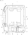
- FIG. 2 is a cross-sectional view illustrating a clothes dryer according to an embodiment of the present disclosure
- FIG. 3 is a perspective view illustrating a heat pump of a clothes dryer according to an embodiment of the present disclosure.
- a clothes dryer 1 may include a main body 10 forming an outer appearance, a drum 12 rotatably installed in the main body 10, a driving device 50 rotating the drum 12, a first duct 20, a second duct 30 and a blowing device 40 which are provided to circulate air into the drum 12, and a heat pump 70 provided to supply hot and dry air into the drum 12.
- the main body 10 is provided in an approximately hexahedron shape. On a front side of the main body 10, a laundry inlet 10a is formed for loading or unloading an object to be dried, and a door 11 is provided for opening or closing the laundry inlet 10a.
- a control panel 15 for controlling the operation of the clothes dryer 1 may be provided on a front upper side of the main body 10.
- a cylindrical drum 12 is provided inside the main body 10.
- the drum 12 is installed to be rotatable by receiving a power of the driving device 50.
- the driving device 50 may include components capable of receiving a rotational force, including a motor 51 and a belt 52.
- the drum 12 is opened to the front of the main body 10 and the door 11 is provided at the laundry inlet 10a to open or close the drum 12 so that an object to be dried may be introduced into or discharged from the drum 12.
- the first duct 20 is provided at a rear side of the drum 12 to communicate with the inside of the drum 12.
- the first duct 20 is formed to communicate with the outside of the main body 10 and is provided to allow the outside air to flow into the drum 12.
- a suction port 21 may be formed on a rear side of the main body 10.
- the first duct 20 is connected to the suction port 21 of the main body 10 and is provided to suck the outside air.
- the first duct 20 forms an intake air flow passage for introducing outside air into the drum.
- first duct 20 is coupled to the rear side of the drum 12 in the present embodiment, the spirit of the present disclosure is not limited thereto.
- first duct may be provided at the lower portion of the drum.
- a heater 23 may be installed in the first duct 20.
- the air introduced through the first duct 20 is heated by the heater 23 and is introduced into the drum 12.
- the heater 23 is provided to heat the air.
- the heater 23 may include a coil heater.
- the heater 23 may be disposed in the first duct 20.
- the heater 23 converts air flowing into the main body 10 through the suction port 21 in the first duct 20 to hot air and then guides the air into the drum 12 to improve a heating efficiency.
- a wet object in the drum 12 is dried by the hot air supplied through the first duct 20 and the hot air having passed through the drum 12 may be discharged through the second duct 30.
- the second duct 30 is provided at a lower side of the drum 12 to communicate with the inside of the drum 12.
- the second duct 30 is arranged to guide discharging of air introduced into the drum 12.
- the second duct 30 forms an exhaust air flow passage which is arranged to discharge the inside air of the drum 12 to the outside of the main body 10.
- the second duct 30 is connected to a filter member 60 provided at a front lower portion of the drum 12, the blowing device 40 installed at a lower side of the drum 12, and a discharge port 31 arranged to communicate with the outside of the rear side of the main body 10.
- the discharge port 31 is formed at a lower rear side of the main body 10.
- the second duct 30 is connected to the discharge port 31 of the main body 10 to discharge the inside air.
- the blowing device 40 installed at the second duct 30 generates an air flow for discharging the air passing through the drum 12 to the outside.
- the blowing device 40 may include a blowing device housing 41 and a blowing fan 42 provided in the blowing device housing 41. Low-temperature and high-humidity air having passed through the drum 12 may be discharged by the blowing fan 42.
- the heat pump 70 may include an evaporator 71, a compressor 73, a condenser 72, and an expansion valve 74.
- the heat pump 70 is configured such that the evaporator 71, the compressor 73, the condenser 72 and the expansion valve 74 are connected with each other by a pipe through which refrigerant flows.
- the evaporator 71 is provided to cool and dehumidify the high-temperature and high-humidity air from the drum 12.
- the condenser 72 is provided to heat the air by condensing the refrigerant.
- the compressor 73 compresses the refrigerant and may include the expansion valve 74 that is provided to maintain a pressure difference of the refrigerant.
- the evaporator 71 and the condenser 72 of the heat pump 70 are arranged to directly heat exchange refrigerant with the air flowing into the main body 10. Since hot and dry air is generated through heat exchange of air and refrigerant through the evaporator 71 and the condenser 72, the evaporator 71 and the condenser 72 may be referred to as a heat exchanger.
- the condenser 72 is referred to as a first heat exchanger
- the evaporator 71 is referred to as a second heat exchanger.
- the first heat exchanger may be disposed in the first duct 20.
- the first heat exchanger heats the air introduced from the outside of the main body 10 into hot air in the first duct 20.
- air in the first duct 20 is heated by the first heat exchanger and the heater 23 such that hot air is supplied into the drum 12.
- the evaporator 71 that is, the second heat exchanger, may be disposed in the second duct 30.
- the first heat exchanger and the second heat exchanger form a vapor compression cycle together with the compressor 73 and the expansion valve.
- the compressor 73 and the expansion valve 74 may be disposed at a lower side of the drum 12 or disposed to be lower than the drum 12.
- the first heat exchanger and the second heat exchanger are connected by a pipe 75 to form one closed loop.
- the vapor compression cycle applies the heat pump principle to air flowing inside the body 10.
- the first heat exchanger and the compressor 73 may supply heat to the inflow air of the first duct 20 to assist in heating the inflow air by the heater 23 and improve the heating efficiency of the inflow air.
- the refrigerant absorbs heat from the humid air coming out of the drum 12 in the second heat exchanger and evaporates. As a result, the air is cooled, and the moisture contained in the air is condensed and drops to the lower side of the main body 10 by gravity.
- the condensed water formed through the heat exchange of the second heat exchanger may be drained to the outside of the main body 10 or stored in a condensate tank 80, which will be described later, or may be used for cleaning the second heat exchanger.
- the condensed water having been used for cleaning the second heat exchanger may be received in the condensate tank 80 and then is discharged to the outside of the main body 10.
- a base frame 70a is provided at a lower side of the evaporator 71 and the condenser 72 of the heat pump 70 to support the evaporator 71 and the condenser 72.
- the refrigerant in the heat pump 70 is evaporated in the evaporator 71, is compressed in the compressor 73 to be high temperature and high pressure, and then is condensed in the condenser 72 by transferring heat to the air.
- the blowing device 40 may be disposed in line with the second heat exchanger. The temperature of air flow by the blowing device 40 of the second duct 30 is lowered while the air flow passes through the second heat exchanger. The air flow by the blowing device 40 may function to easily remove the condensed water generated on the surface of the second heat exchanger.
- moisture contained in the high temperature and high humidity air is condensed on the surface of the second heat exchanger or fall to the downside of the second heat exchanger.
- the condensed water may be transferred to the condensate tank 80 by the base frame 70a positioned at a lower side of the second heat exchanger.
- the condensate tank 80 may be integrally formed with the base frame 70a.
- the condensate tank 80 is positioned lower than the base frame 70a so that the condensed water of the base frame 70a is easily transferred to the condensate tank 80 by gravity.
- the condensed water in the condensate tank 80 may be drained to the outside of the main body 10 by a pump 81 or may be supplied to a spray member 100 which will be described later.
- the pump 81 is provided in the condensate tank 80.
- the pump 81 is arranged to pump the condensed water in the condensate tank 80.
- the pump 81 is connected to a valve 82.
- the valve 82 is connected to the pump 81 by a connecting pipe 84.
- the valve 82 is connected to a drain pipe 83 and the connecting pipe 84.
- the drain pipe 83 is connected to the outside of the main body 10 and the connecting pipe 84 may be connected to the spray member 100.
- the pump 81 may include a controller 88 that controls a speed and an amount of spraying of the condensed water.
- the valve 82 may discharge the condensed water of the condensate tank 80 to the outside of the main body 10 through the drain pipe 83 or may supply the condensed water to the spray member 100 through the connecting pipe 84.
- a filter member 60 may be installed at the front end of the second duct 30 to filter foreign matter, such as dust or lint, contained in the hot air discharged from the drum 12.
- the filter member 60 may be provided on the lower surface of the drum 12.
- the filter member 60 is arranged to prevent the foreign matter from flowing into the first duct 20 while the hot and dry air supplied into the drum 12 passes through the wet laundry and then is discharged from the drum 12.
- the foreign matter in the air flowing into the second duct 30 is primarily filtered by the filter member 60
- the foreign matter such as lint that is not filtered by the filter member 60 flows into the second heat exchanger of the heat pump 70 and may block the air flow path.
- the spray member 100 for cleaning the foreign matter of the second heat exchanger is arranged to prevent clogging of the air flow path of the second heat exchanger.
- the spray member 100 is installed to uniformly spray the condensed water of the condensate tank 80 into the second heat exchanger.
- the spray member 100 is provided on the upper side of the second heat exchanger.
- the spray member 100 may be installed on the air inlet side of the second heat exchanger.
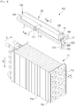
- FIG. 4 is an exploded perspective view illustrating a spray member coupled to an evaporator in a clothes dryer according to an embodiment of the present disclosure
- FIG. 5 is a cross-sectional view taken along line A-A' in FIG. 4
- FIG. 6 is a bottom view illustrating a spray member according to an embodiment of the present disclosure
- FIG. 7 is a cross-sectional view taken along line B-B 'in FIG. 6 .
- the spray member 100 may include an inlet portion 110 through which the condensed water is introduced and a spray portion 120 arranged to uniformly spray the condensed water introduced through the inlet portion 110 onto the surface of the second heat exchanger.
- the spray portion 120 may include a guide surface 130, at least a portion of which is formed as a curved surface having a constant curvature R, to guide the condensed water.
- the spray member 100 may be injection molded.
- the inlet portion 110 and the spray portion 120 of the spray member 100 may be integrally injection-molded with each other.
- the inlet portion 110 is formed as a pipe to which the connecting pipe 84 provided for connection with the pump 81 and the valve 82 of the condensate tank 80 is coupled.
- the inlet portion 110 includes an inlet 111 to which condensed water is introduced.
- the spray portion 120 includes the guide surface 130.
- the guide surface 130 may include a guide support surface 131, an upper surface 132, a curved surface 133, a spray surface 134, and opposite side surfaces 135.
- the guide support surface 131 may form a rear surface of the spray portion 120 and the inlet portion 110 may be connected to an upper center of the guide support surface 131.
- the upper surface 132 is connected to an upper end of the guide support surface 131.
- the curved surface 133 having the curvature R may be formed between the upper surface 132 and the spray surface 134.
- the spray surface 134 is disposed to face the guide support surface 131.
- the guide support surface 131, the upper surface 132, the curved surface 133, and the spray surface 134 may be connected to each other by the opposite side surfaces 135.
- the guide support surface 131 and the spray surface 134 may be spaced apart from each other.
- the gap G between the guide support surface 131 and the spray surface 134 may be formed by a width corresponding to the upper surface 132.
- the gap G between the guide support surface 131 and the spray surface 134 forms a discharge port 137 through which the condensed water guided by the guide surface 130 is discharged.
- the spaced gap G between the guide support surface 131 and the spray surface 134 may be positioned to correspond to an upper end of the second heat exchanger.
- the gap G between the guide supporting surface 131 and the spray surface 134 may be disposed adjacent to the upper end of the second heat exchanger.
- the gap G between the guide support surface 131 and the spray surface 134 is formed to become narrower from the center toward opposite sides. That is, the gap between the guide support surface 131 and the spray surface 134 at a center portion (a first interval L1) is wider than the gap between the guide support surface 131 and the spray surface 134 opposite end portions (a second intervals L2) .
- the spray surface 134 may be formed as a curved surface having a predetermined curvature.
- the spray surface 134 is formed as a curved surface that is gradually closer to the guide support surface 131 from the center to opposite end portions.
- the difference between the first interval L1 and the second interval L2 formed between the guide support surface 131 and the spray surface 134 allows the condensed water to be uniformly sprayed to the second heat exchanger in consideration of difference in flow speed of the condensed water introduced through the inlet 111.
- the curved surface 133 connecting between the upper surface 132 and the spray surface 134 of the guide surface 130 may have a constant curvature.
- the guide surface 130 may have a shape bent in a second direction B downwardly perpendicular to a first direction A in which the condensed water is introduced.
- the guide surface 130 may be formed to have a letter ' ' shape.
- the upper surface 132 of the guide surface 130 is provided with a guide rib 160 for guiding the condensed water supplied through the inlet portion 110.
- the guide rib 160 guides the condensed water so that the condensed water is supplied to opposite ends of the guide surface 130.
- the guide rib 160 may be radially disposed from the center toward opposite sides of the guide surface 130 so that the condensed water is guided from the center to the opposite ends.
- the guide rib 160 may protrude inward from the upper surface 132.
- a plurality of protrusions 152 and grooves 151 may be formed on the spray surface 134 of the guide surface 130.
- the plurality of protrusions 152 and the grooves 151 are formed so as to increase the impact force applied to the surface of the second heat exchanger when the condensed water is sprayed.
- the plurality of protrusions 152 may be spaced apart at regular intervals.
- the plurality of grooves 151 may be spaced apart at regular intervals.
- the plurality of protrusions 152 and the grooves 151 may be alternately arranged.
- the plurality of grooves 151 are formed by the plurality of protrusions 152 in the embodiment of the present disclosure, the concept of the present disclosure is not limited thereto.
- the plurality of grooves 151 may be recessed inward with a semicircular shape.
- the spray member 100 may include a frame 140 provided around the spray portion 120 and a fastening portion 200 provided on the frame 140.
- the frame 140 may extend from a lower edge of the spray portion 120.
- the frame 140 is formed in a rectangular shape.
- the frame 140 of the spray member 100 is shown as being rectangular in the embodiment of the present invention, the spirit of the present invention is not limited thereto.
- the frame may be formed to correspond to the size and shape of the second heat exchanger.
- the second heat exchanger may include a cooling tube 71a in which the refrigerant flows and a cooling fin 71b installed on the cooling tube 71a.
- the cooling tube 71a has a predetermined thickness t1 so that the refrigerant for heat exchange flows therein.
- the second heat exchanger may include a support bracket 71c arranged to fix the cooling tube 71a and the cooling fin 71b.
- the support brackets 71c may be disposed at opposite ends of the second heat exchanger.
- the second heat exchanger may be formed in an approximately hexahedron.
- the spray member 100 may be disposed on the upper side of the second heat exchanger.
- the spray member 100 may be directly installed on the second heat exchanger.
- the spray member 100 includes the fastening portion 200.
- the fastening portion 200 may include a connecting bracket 210, a coupling groove 220 formed in the connecting bracket 210, and a fixing protrusion 230 formed in the coupling groove 220.
- the fastening portion 200 may be integrally injection-molded with the frame 140 of the spray member 100.
- the connecting brackets 210 are formed to protrude downward at opposite ends of the frame 140.
- the connecting brackets 210 may be installed directly on the cooling tube 71a protruding from opposite ends of the second heat exchanger.
- the connecting brackets 210 are formed in a plate shape at the opposite ends of the frame 140.
- the coupling groove 220 extends from a lower end of the connecting bracket 210 to the upper side with a predetermined length.
- the coupling groove 220 is formed so that the cooling tube 71a of the second heat exchanger is inserted thereto.
- the coupling groove 220 may have a gap t2 equal to the thickness t1 of the cooling tube 71a.
- the coupling groove 220 is formed so that the cooling tube 71a is insertedly fixed to the coupling groove 220.
- the fixing protrusion 230 is formed in the coupling groove 220 so that the cooling tube 71a is insertedly fixed to the fixing protrusion 230.
- the fixing protrusion 230 is formed to protrude inward of the coupling groove 220 and to fix the cooling tube 71a.
- a gap t3 between the fixing protrusions 230 may be smaller than the thickness t1 of the cooling tube 71a.
- a guide 161 may be formed on a bottom surface of the frame 140 to support the support bracket 71c of the second heat exchanger.
- the guide 161 is arranged to guide an assembly position in which the spray member 100 is installed on the second heat exchanger.
- the guide 161 allows the installation position of the spray member 100 to be determined, so that a spray position of the condensed water may be accurately set.
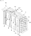
- FIG. 8 is a view illustrating a spray operation of a spray member according to an embodiment of the present disclosure
- FIG. 9 is a cross-sectional view illustrating a spray operation of a spray member according to an embodiment of the present disclosure.
- the condensed water introduced through the inlet portion 110 of the spray member 100 is guided by the guide surface 130 of the spray portion 12 to be sprayed onto the surface of the second heat exchanger.
- the condensed water is sprayed to the inlet side of the air flow path of the second heat exchanger.
- Condensed water mixed with foreign matters such as lint by the condensed water sprayed to the inlet side of the air flow path of the second heat exchanger is collected to the condensate tank 80 through the base frame 70a.
- the condensed water mixed with foreign matters such as lint is stored in the condensate tank 80 together with the condensed water sprayed to the inlet side of the air flow path of the second heat exchanger and then is discharged to the outside of the main body 10 through the drain pipe 83 by the pump 81 and the valve 82.
- FIG. 10 is a perspective view illustrating a spray member according to another embodiment of the present disclosure
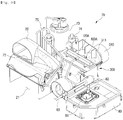
- FIG. 11 is an exploded perspective view illustrating a spray member and a duct cover according to another embodiment of the present disclosure
- FIG. 12 is a view illustrating a flow of condensed water by a spray member and an air flow by a duct cover according to another embodiment of the present disclosure. Reference numerals not shown refer to FIGS. 1 to 9 .
- a spray member 100A may be installed on a duct cover 300 of the second heat exchanger.
- the second heat exchanger is installed on the base frame 70a.
- the second heat exchanger is provided in the second duct 30 to perform heat-exchange with the low temperature and high humidity air inside the drum 12.
- the second heat exchanger may include the duct cover 300 that guides air to the outside of the main body 10.
- the duct cover 300 is arranged to surround the second heat exchanger and communicate with the second duct 30 to communicate with the discharge port 31 of the main body 10.
- the duct cover 300 includes a first duct cover 310 arranged to surround an upper side of the second heat exchanger, and the base frame 70a coupled to the first duct cover 310 to surround a lower side of the second heat exchanger.
- the second heat exchanger is installed on the base frame and the base frame is arranged to surround the lower side of the second heat exchanger, but the spirit of the present disclosure is not limited thereto.
- a separate second duct cover may be provided to surround the lower side of the second heat exchanger.
- a support rib 311 may be formed on an upper surface of the first duct cover 310 to support a lower portion of the drum 12.
- the duct cover 300 is arranged to surround the second heat exchanger to form a flow path S of air passing through the second heat exchanger.
- the upper surface of the first duct cover 310 may be provided with a mounting hole 330 for installing the spray member 100A at a position corresponding to the air inlet side of the second heat exchanger.
- the mounting hole 330 may be formed to have a size corresponding to a width of the second heat exchanger.
- a supporting surface 331 may be formed on a rim of the mounting hole 330 of the first duct cover 310 to support the spray member 100A.
- the spray member 100A includes a connecting portion 110A, a spray portion 120A having a guide surface 130 to guide the condensed water introduced through the connecting portion 110A, and a frame 140A formed around the spray portion 120A.
- a support portion 141A is formed on a bottom surface of the frame 140A and may be coupled to the supporting surface 331 of the first duct cover 310.
- the spray member 100A is provided with a fastening portion 400A for coupling to the first duct cover 310.
- the fastening portion 400A includes a fastening hole 410A formed integrally with the frame 140A of the spray member 100A and a fastening protrusion 420A formed on the first duct cover 310 to correspond to the fastening hole 410A.
- the fastening portion 400A is shown as the fastening protrusion 420A and the fastening hole 410A, the spirit of the present disclosure is not limited thereto.
- the fastening portion may include a structure such as a hook capable of coupling the spray member 100A to the first duct cover 310.
- the spray member is shown as being coupled to the first duct cover 310 by the fastening portion 400A, but the spirit of the present disclosure is not limited thereto.
- the spray member may be integrally injection-molded with the duct cover.
- FIG. 13 is a perspective view illustrating a spray member according to another embodiment of the present disclosure
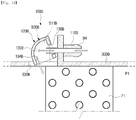
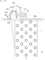
- FIGS. 14 and 15 are views illustrating a condensed water spray operation of a spray member according to another embodiment of the present disclosure. Reference numerals not shown refer to FIGS. 1 to 12 .
- a spray member 100B is movably mounted on a duct cover 300B.
- the spray member 100B is rotatably mounted on the upper side of the second heat exchanger.
- the spray member 100B is disposed on the air inlet side of the second heat exchanger.
- the spray member 100B may include an inlet portion 110B through which the condensed water introduced and a spray portion 120B having a guide surface 130B to guide the introduced condensed water.
- the inlet portion 110B is formed as a pipe to which the connecting pipe 84 provided for connection with the pump 81 and the valve 82 of the condensate tank 80 is coupled.
- the spray portion 120B includes the guide surface 130B.
- the guide surface 130B may include a guide support surface 131B, an upper surface 132B, a curved surface 133B, a spray surface 134B, and opposite side surfaces 135B.
- the guide support surface 131B may form a rear surface of the spray portion 120B and a movement slot 136B is formed on an upper center portion of the guide support surface 131B so that the inlet portion 110 is connected thereto.
- the movement slot 136B is formed in a vertical direction to prevent interference of the inlet portion 110B upon rotation of the spray portion 120B.
- the spray portion 120B is rotatably coupled to the duct cover 300B through a hinge member 500B.
- the hinge member 500B is installed at opposite ends of the mounting hole 330B of the duct cover 300B.
- the hinge member 500B includes a hinge bracket 510B and a rotating shaft 511B formed on the spray portion 120B to be coupled to the hinge bracket 510B.
- the rotating shafts 511B may be formed on the opposite side surfaces 135B of the spray portion 120B, respectively.
- the spray portion 120B may be rotatably coupled to the duct cover 300B by the hinge member 500B. Meanwhile, in the embodiment of the present disclosure, the spray portion 120B is illustrated as being rotated by the hinge member 500B, but the spirit of the present disclosure is not limited thereto. For example, the spray portion 120B may be provided on the duct cover 300B to slide forward, backward, leftward and rightward.
- the spray portion120B is not rotated and the condensed water is sprayed by the curved surface 133B of the guide surface 130B such that the condensed water is sprayed to a first position P1 that is an upper side of the second heat exchanger.
- the spray portion 120B rotates around the rotating shaft 511B.
- the large amount of condensed water flowing into the spray portion 120B rotated about the rotating shaft 511B is sprayed by the spray surface 134B of the guide surface 130B of the spray portion 120B such that the condensed water is sprayed to a second position P2 that is a lower side of the second heat exchanger.
- a rotation angle of the spray portion 120B may be adjusted by controlling a pressure of the condensed water through control of the pump 81.
- the rotation angle of the spray portion 120B may be controlled by a driving force of a motor (not shown) provided separately.
- FIGS. 16 and 17 are views illustrating a condensed water spray operation of a spray member according to another embodiment of the present disclosure. Reference numerals not shown refer to FIGS. 1 to 12 .
- a spray member 100C is movably mounted on a duct cover 300C.
- the spray member 100C is rotatably mounted on the upper side of the second heat exchanger.
- the spray member 100C is disposed on the air inlet side of the second heat exchanger.
- the spray member 100C may include an inlet portion 110C through which the condensed water is introduced and a spray portion 120C having a guide surface 130C to guide the introduced condensed water.
- the spray portion 120C includes the guide surface 130C.
- the guide surface 130C may include a guide support surface 131C, an upper surface 132C, a curved surface 133C, a spray surface 134C, and opposite side surfaces 135C.
- the guide support surface 131C may form a rear surface of the spray portion 120C and a movement slot 136C is formed on an upper center portion of the guide support surface 131C so that the inlet portion 110C is connected thereto.
- the movement slot 136C is formed in a vertical direction to prevent interference of the inlet portion 110C upon rotation of the spray portion 120C.
- the spray portion 120C is rotatably coupled to the duct cover 300C through a hinge member 500B.
- the hinge member 500B is installed at opposite ends of the mounting hole 330C of the duct cover 300C.
- the hinge member 500B includes a hinge bracket 510B and a rotating shaft 511B formed on the spray portion 120C to be coupled to the hinge bracket 510B.
- the rotating shafts 511B may be formed on the opposite side surfaces 135B of the spray portion 120C, respectively.
- the spray portion 120C may be rotatably coupled to the duct cover 300C by the hinge member 500B.
- the spray portion 120C may further include an elastic member 500C.
- the spray portion 120C may include the elastic member 500C configured to press the spray portion 120C in a direction opposite to the first direction A, in which the condensed water is introduced.
- the spray portion120C in a position rotated by the elastic member 500C is prevented from being rotated due to the elastic force of the elastic member 500C, and the condensed water is guided by the curved surface 133C of the guide surface 130C to be sprayed to the first position P1 that is an upper side of the second heat exchanger.
- the spray portion 120C presses the elastic member 500C and rotates around the rotating shaft 511B.
- the large amount of condensed water flowing into the spray portion 120C rotated about the rotating shaft 511B is guided by the spray surface 134C of the guide surface 130C of the spray portion 120C such that the condensed water is sprayed to the second position P2 that is a lower side of the second heat exchanger.
- FIGS. 18 and 19 are views illustrating a condensed water spray operation of a spray member according to another embodiment of the present disclosure. Reference numerals not shown refer to FIGS. 13 to 15 .
- a spray member 100D is movably mounted on a duct cover 300D.
- the spray member 100D is rotatably mounted on the upper side of the second heat exchanger.
- the spray member 100D is disposed on the air inlet side of the second heat exchanger.
- the spray member 100D may include an inlet portion 110D through which the condensed water introduced and a spray portion 120D having a guide surface 130D to guide the introduced condensed water.
- the spray portion 120D includes the guide surface 130D.
- the guide surface 130D may include a guide support surface 131D, an upper surface 132D, a curved surface 133D, a spray surface 134D, and opposite side surfaces 135D.
- the guide support surface 131D may form a rear surface of the spray portion 120D and a movement slot 136D is formed on an upper center portion of the guide support surface 131D so that the inlet portion 110D is connected thereto.
- the movement slot 136D is formed in a vertical direction to prevent interference of the inlet portion 110d upon rotation of the spray portion 120D.
- the spray portion 120D is rotatably coupled to the duct cover 300D through a hinge member 500B.
- the hinge member 500B is installed at opposite ends of the mounting hole 330D of the duct cover 300D.
- the hinge member 500B includes a hinge bracket 510B and a rotating shaft 511B formed on the spray portion 120D to be coupled to the hinge bracket 510B.
- the rotating shafts 511B may be formed on opposite side surfaces 135D of the spray portion 120D, respectively.
- the spray portion 120D may be rotatably coupled to the duct cover 300D by the hinge member 500B.
- the spray portion 120D which rotates about the rotating shaft 511B of the hinge member 500B, guides the condensed water in a state rotated by its own weight.
- the spray portion120D is not rotated and the condensed water is guided by the curved surface 133D of the guide surface 130D to be sprayed to the first position P1 that is an upper side of the second heat exchanger.
- the spray portion 120D rotates around the rotating shaft 511B.
- the rotated spray portion 120D guides the condensed water through the spray surface 134D of the guide surface 130D so that the condensed water is sprayed to the second position P2 that is a lower side of the second heat exchanger.
- the spray portion 120D may further include a stopper 500D to prevent the spray portion 120D from rotating.
- the stopper 500D includes a first stopper 501D disposed on an upper side of the spray portion 120D to support a position where spray portion 120D does not rotate due to its own weight, and a second stopper 502D disposed on a lower side of the spray portion 120D to restrict rotation of the spray portion 120D when the spray portion 120D is rotated by the water pressure of the condensed water.
- the water pressure of the condensed water for controlling the rotation of the spray portion 120D may be controlled by on/off operation of the pump 81.
- the condensed water may be evenly distributed over various portions of the upper and lower sides of the second heat exchanger, thereby improving the cleaning efficiency of the heat exchanger.
Landscapes
- Engineering & Computer Science (AREA)
- Textile Engineering (AREA)
- Detail Structures Of Washing Machines And Dryers (AREA)
Description
- Embodiments disclosed herein relate to a clothes dryer, and more particularly, to a clothes dryer for improving a cleaning structure of a heat exchanger.
- Generally, a clothes dryer is a machine for blowing hot air into a drying drum to dry wet laundry placed in the drying drum. The clothes dryer is basically similar to a drum washing machine in its appearance, and dries laundry by forcibly circulating hot air into the drying drum through a heater and a blower fan.
- The clothes dryer may include a condensing-type dryer and an exhaust-type dryer.
- In the condensing-type dryer, air which is humidified through heat-exchange with laundry in a drying drum is circulated without being discharged to the outside of the dryer. The humidified air is heat-exchanged with external air in a separate condenser to produce condensed water, and the condensed water is discharged to the outside.
- In the exhaust-type dryer, the air, which is humidified through heat-exchange with laundry in a drying drum is directly discharged to the outside of the dryer.
- Since the condensing-type dryer uses a heat pump, low energy consumption and high thermal efficiency are ensured, thus it is widely being used in recent years.
- The heat pump has an evaporator, a compressor, and a condenser where refrigerant circulates. Lint and foreign matter generated in the drying drum may accumulate on an inlet side of an air flow path to the evaporator.
-
WO 2009/031812 A2 discloses a clothes dryer according to the preamble ofclaim 1. - European patent application
EP 2 386 679 A1 is directed to a clothes dryer comprising a rotatable drum, a dehumidification unit for condensing moisture from the air discharged from the drum and including an evaporator and a condenser, a cleaning water tank for collecting condensed water and a cleaning nozzle spraying the condensed water from the tank onto a filter covering the condenser. - Furthermore,
US 20130340797 A1 discloses a clothes treatment appliance comprising a rotatable drum, a compressor-type heat pump including a heater and a condenser, a collection unit for receiving condensed water from the condenser, and a transfer pipe and water diversion means configured to spray the condensed water from the collection unit to the condenser to clean the condenser, - It is an aspect of the present disclosure to provide a clothes dryer having a structure capable of cleaning a heat exchanger by using condensed water.
- It is another aspect of the present disclosure to provide a clothes dryer capable of improving spray accuracy by directly mounting a spray member on a heat exchanger.
- It is another aspect of the present disclosure to provide a clothes dryer capable of improving cleaning efficiency of a heat exchanger.
- In accordance with an aspect of the present disclosure, a clothes dryer includes a main body, a drum rotatably provided in the main body, a heat pump including an evaporator, a compressor, a condenser, and an expansion valve to supply hot and dry air into the drum, a condensate tank to receive condensed water generated from the heat pump, and a spray member configured to spray the condensed water of the condensate tank to the evaporator. The spray member includes an inlet portion through which the condensed water is introduced and a spray portion having a guide surface provided such that the condensed water introduced through the inlet portion is uniformly sprayed onto a surface of the evaporator. At least a portion of the guide surface includes a curved surface having a constant curvature. The evaporator comprises at least a cooling tube in which the refrigerant flows and a cooling fin installed on the cooling tube. The spray member includes a fastening portion fastened to the cooling tube protruding from opposite ends of the evaporator so that the cooling tube is inserted in the fastening portion.
- The inlet portion and the spray portion may be integrally injection-molded.
- The guide surface may be bent vertically.
- The guide surface may include a plurality of protrusions and grooves formed to disperse the condensed water.
- The clothes dryer may further include a frame provided around the spray portion and the fastening portion may be formed on the frame.
- The fastening portion may include a connection bracket provided on the frame, a coupling groove for coupling with the evaporator, and a fixing protrusion formed in the coupling groove.
- The spray portion may include at least one guide rib formed to guide the condensed water.
- The spray portion may be installed to be movable.
- The spray portion may further include a hinge portion.
- The clothes dryer may further include a pump to pump the condensed water from the condensate tank.
- The condensate tank may include a valve provided to supply a portion of the condensed water to the spray member and discharge the remaining portion of the condensed water to the outside of the main body.
- The spray member may be injection molded.
- The clothes dryer may further include a first duct connected to the drum to supply outside air, a second duct configured to discharge inside air of the drum, and a blower provided in the second duct.
- The clothes dryer may further include a duct cover forming the second duct. The spray member may be connected to the duct cover.
- In accordance with another aspect of the present disclosure, a clothes dryer includes a drum provided to be rotatable, a heat pump including an evaporator, a compressor, a condenser, and an expansion valve to supply air into the drum, a condensate tank to receive condensed water generated from the heat pump, and a spray member configured to spray the condensed water in the condensate tank to the evaporator. The spray member includes an inlet portion through which the condensed water is introduced and a spray portion having a guide surface at least a portion of which is provided as a curved surface having a constant curvature such that the condensed water introduced through the inlet portion is uniformly sprayed onto a surface of the evaporator. The inlet portion and the spray portion are integrally injection-molded.
- The guide surface may include a plurality of protrusions and grooves.
- The spray portion may be installed to be movable.
- The clothes dryer may further include a stopper provided to limit the movement of the spray portion.
- The clothes dryer may further include a pump to pump the condensed water from the condensate tank.
- The evaporator may include a duct cover, and the spray member may be integrally injection-molded with the duct cover.
- In accordance with another aspect of the present disclosure, a clothes dryer includes a drum provided to be rotatable, a heat pump including an evaporator, a compressor, a condenser, and an expansion valve to supply air into the drum, a condensate tank to receive condensed water generated from the heat pump, and a spray member configured to spray the condensed water in the condensate tank to the evaporator. The spray member includes fastening portions configured to be fastened to opposite ends of the evaporator.
- The evaporator may include a cooling tube and a cooling fin coupled to the cooling tube. The fastening portions may be coupled to the cooling tube.
- The fastening portions may include a connection bracket provided on the spray member and a coupling groove formed on the connection bracket.
- The coupling groove may include a fixing protrusion formed to fix the cooling tube.
- The spray member and the fastening portions may be integrally injection-molded.
- In accordance with one aspect of the present disclosure, it may be possible to clean a heat exchanger by using condensed water.
- In addition, the condensed water can be accurately sprayed onto a surface of the heat exchanger, thereby improving an efficiency of washing the heat exchanger.
-
-
FIG. 1 is a perspective view illustrating an outer appearance of a clothes dryer according to an embodiment of the present disclosure. -
FIG. 2 is a cross-sectional view illustrating a clothes dryer according to an embodiment of the present disclosure. -
FIG. 3 is a perspective view illustrating a heat pump of a clothes dryer according to an embodiment of the present disclosure. -
FIG. 4 is an exploded perspective view illustrating a spray member coupled to an evaporator in a clothes dryer according to an embodiment of the present disclosure. -
FIG. 5 is a cross-sectional view taken along line A-A' inFIG. 4 . -
FIG. 6 is a bottom view illustrating a spray member according to an embodiment of the present disclosure. -
FIG. 7 is a cross-sectional view taken along line B-B 'inFIG. 6 . -
FIG. 8 is a view illustrating a spray operation of a spray member according to an embodiment of the present disclosure. -
FIG. 9 is a cross-sectional view illustrating a spray operation of a spray member according to an embodiment of the present disclosure. -
FIG. 10 is a perspective view illustrating a spray member according to another embodiment of the present disclosure. -
FIG. 11 is an exploded perspective view illustrating a spray member and a duct cover according to another embodiment of the present disclosure. -
FIG. 12 is a view illustrating a flow of condensed water by a spray member and an air flow by a duct cover according to another embodiment of the present disclosure. -
FIG. 13 is a perspective view illustrating a spray member according to another embodiment of the present disclosure. -
FIGS. 14 and15 are views illustrating a condensed water spray operation of a spray member according to another embodiment of the present disclosure. -
FIGS. 16 and17 are views illustrating a condensed water spray operation of a spray member according to another embodiment of the present disclosure. -
FIGS. 18 and19 are views illustrating a condensed water spray operation of a spray member according to another embodiment of the present disclosure. - Hereinafter, exemplary embodiments according to the present disclosure will be described in detail with reference to the accompanying drawings. The terms "front end", "rear end", "upper", "lower", "upper end" and "lower end" used in the following description are defined based on the drawings. The shape and position of each component should not be limited by these terms.
-
FIG. 1 is a perspective view illustrating an outer appearance of a clothes dryer according to an embodiment of the present disclosure,FIG. 2 is a cross-sectional view illustrating a clothes dryer according to an embodiment of the present disclosure, andFIG. 3 is a perspective view illustrating a heat pump of a clothes dryer according to an embodiment of the present disclosure. - As illustrated in
FIGS. 1 to 3 , aclothes dryer 1 may include amain body 10 forming an outer appearance, adrum 12 rotatably installed in themain body 10, a drivingdevice 50 rotating thedrum 12, afirst duct 20, asecond duct 30 and ablowing device 40 which are provided to circulate air into thedrum 12, and aheat pump 70 provided to supply hot and dry air into thedrum 12. - The
main body 10 is provided in an approximately hexahedron shape. On a front side of themain body 10, alaundry inlet 10a is formed for loading or unloading an object to be dried, and adoor 11 is provided for opening or closing thelaundry inlet 10a. Acontrol panel 15 for controlling the operation of theclothes dryer 1 may be provided on a front upper side of themain body 10. - A
cylindrical drum 12 is provided inside themain body 10. Thedrum 12 is installed to be rotatable by receiving a power of the drivingdevice 50. The drivingdevice 50 may include components capable of receiving a rotational force, including amotor 51 and abelt 52. - The
drum 12 is opened to the front of themain body 10 and thedoor 11 is provided at thelaundry inlet 10a to open or close thedrum 12 so that an object to be dried may be introduced into or discharged from thedrum 12. - The
first duct 20 is provided at a rear side of thedrum 12 to communicate with the inside of thedrum 12. Thefirst duct 20 is formed to communicate with the outside of themain body 10 and is provided to allow the outside air to flow into thedrum 12. Asuction port 21 may be formed on a rear side of themain body 10. Thefirst duct 20 is connected to thesuction port 21 of themain body 10 and is provided to suck the outside air. Thefirst duct 20 forms an intake air flow passage for introducing outside air into the drum. - Although the
first duct 20 is coupled to the rear side of thedrum 12 in the present embodiment, the spirit of the present disclosure is not limited thereto. For example, the first duct may be provided at the lower portion of the drum. - A
heater 23 may be installed in thefirst duct 20. The air introduced through thefirst duct 20 is heated by theheater 23 and is introduced into thedrum 12. - The
heater 23 is provided to heat the air. Theheater 23 may include a coil heater. Theheater 23 may be disposed in thefirst duct 20. Theheater 23 converts air flowing into themain body 10 through thesuction port 21 in thefirst duct 20 to hot air and then guides the air into thedrum 12 to improve a heating efficiency. - A wet object in the
drum 12 is dried by the hot air supplied through thefirst duct 20 and the hot air having passed through thedrum 12 may be discharged through thesecond duct 30. - The
second duct 30 is provided at a lower side of thedrum 12 to communicate with the inside of thedrum 12. Thesecond duct 30 is arranged to guide discharging of air introduced into thedrum 12. Thesecond duct 30 forms an exhaust air flow passage which is arranged to discharge the inside air of thedrum 12 to the outside of themain body 10. - The
second duct 30 is connected to afilter member 60 provided at a front lower portion of thedrum 12, the blowingdevice 40 installed at a lower side of thedrum 12, and adischarge port 31 arranged to communicate with the outside of the rear side of themain body 10. - The
discharge port 31 is formed at a lower rear side of themain body 10. Thesecond duct 30 is connected to thedischarge port 31 of themain body 10 to discharge the inside air. - The blowing
device 40 installed at thesecond duct 30 generates an air flow for discharging the air passing through thedrum 12 to the outside. The blowingdevice 40 may include ablowing device housing 41 and a blowingfan 42 provided in theblowing device housing 41. Low-temperature and high-humidity air having passed through thedrum 12 may be discharged by the blowingfan 42. - Meanwhile, the
heat pump 70 may include anevaporator 71, acompressor 73, acondenser 72, and anexpansion valve 74. Theheat pump 70 is configured such that theevaporator 71, thecompressor 73, thecondenser 72 and theexpansion valve 74 are connected with each other by a pipe through which refrigerant flows. Theevaporator 71 is provided to cool and dehumidify the high-temperature and high-humidity air from thedrum 12. Thecondenser 72 is provided to heat the air by condensing the refrigerant. - The
compressor 73 compresses the refrigerant and may include theexpansion valve 74 that is provided to maintain a pressure difference of the refrigerant. - The
evaporator 71 and thecondenser 72 of theheat pump 70 are arranged to directly heat exchange refrigerant with the air flowing into themain body 10. Since hot and dry air is generated through heat exchange of air and refrigerant through theevaporator 71 and thecondenser 72, theevaporator 71 and thecondenser 72 may be referred to as a heat exchanger. - Hereinafter, the
condenser 72 is referred to as a first heat exchanger, and theevaporator 71 is referred to as a second heat exchanger. - The first heat exchanger may be disposed in the
first duct 20. The first heat exchanger heats the air introduced from the outside of themain body 10 into hot air in thefirst duct 20. - Accordingly, air in the
first duct 20 is heated by the first heat exchanger and theheater 23 such that hot air is supplied into thedrum 12. - The
evaporator 71, that is, the second heat exchanger, may be disposed in thesecond duct 30. The first heat exchanger and the second heat exchanger form a vapor compression cycle together with thecompressor 73 and the expansion valve. Thecompressor 73 and theexpansion valve 74 may be disposed at a lower side of thedrum 12 or disposed to be lower than thedrum 12. The first heat exchanger and the second heat exchanger are connected by apipe 75 to form one closed loop. The vapor compression cycle applies the heat pump principle to air flowing inside thebody 10. The first heat exchanger and thecompressor 73 may supply heat to the inflow air of thefirst duct 20 to assist in heating the inflow air by theheater 23 and improve the heating efficiency of the inflow air. - On the other hand, the refrigerant absorbs heat from the humid air coming out of the
drum 12 in the second heat exchanger and evaporates. As a result, the air is cooled, and the moisture contained in the air is condensed and drops to the lower side of themain body 10 by gravity. - The condensed water formed through the heat exchange of the second heat exchanger may be drained to the outside of the
main body 10 or stored in acondensate tank 80, which will be described later, or may be used for cleaning the second heat exchanger. - The condensed water having been used for cleaning the second heat exchanger may be received in the
condensate tank 80 and then is discharged to the outside of themain body 10. - A
base frame 70a is provided at a lower side of theevaporator 71 and thecondenser 72 of theheat pump 70 to support theevaporator 71 and thecondenser 72. - The refrigerant in the
heat pump 70 is evaporated in theevaporator 71, is compressed in thecompressor 73 to be high temperature and high pressure, and then is condensed in thecondenser 72 by transferring heat to the air. Further, the blowingdevice 40 may be disposed in line with the second heat exchanger. The temperature of air flow by the blowingdevice 40 of thesecond duct 30 is lowered while the air flow passes through the second heat exchanger. The air flow by the blowingdevice 40 may function to easily remove the condensed water generated on the surface of the second heat exchanger. - In the process of cooling the air by the second heat exchanger, moisture contained in the high temperature and high humidity air is condensed on the surface of the second heat exchanger or fall to the downside of the second heat exchanger. The condensed water may be transferred to the
condensate tank 80 by thebase frame 70a positioned at a lower side of the second heat exchanger. - The
condensate tank 80 may be integrally formed with thebase frame 70a. Thecondensate tank 80 is positioned lower than thebase frame 70a so that the condensed water of thebase frame 70a is easily transferred to thecondensate tank 80 by gravity. - The condensed water in the
condensate tank 80 may be drained to the outside of themain body 10 by apump 81 or may be supplied to aspray member 100 which will be described later. - The
pump 81 is provided in thecondensate tank 80. Thepump 81 is arranged to pump the condensed water in thecondensate tank 80. Thepump 81 is connected to avalve 82. Thevalve 82 is connected to thepump 81 by a connectingpipe 84. Thevalve 82 is connected to adrain pipe 83 and the connectingpipe 84. Thedrain pipe 83 is connected to the outside of themain body 10 and the connectingpipe 84 may be connected to thespray member 100. - The
pump 81 may include acontroller 88 that controls a speed and an amount of spraying of the condensed water. - The
valve 82 may discharge the condensed water of thecondensate tank 80 to the outside of themain body 10 through thedrain pipe 83 or may supply the condensed water to thespray member 100 through the connectingpipe 84. - A
filter member 60 may be installed at the front end of thesecond duct 30 to filter foreign matter, such as dust or lint, contained in the hot air discharged from thedrum 12. Thefilter member 60 may be provided on the lower surface of thedrum 12. - The
filter member 60 is arranged to prevent the foreign matter from flowing into thefirst duct 20 while the hot and dry air supplied into thedrum 12 passes through the wet laundry and then is discharged from thedrum 12. - Although foreign matter in the air flowing into the
second duct 30 is primarily filtered by thefilter member 60, the foreign matter such as lint that is not filtered by thefilter member 60 flows into the second heat exchanger of theheat pump 70 and may block the air flow path. - Therefore, the
spray member 100 for cleaning the foreign matter of the second heat exchanger is arranged to prevent clogging of the air flow path of the second heat exchanger. - The
spray member 100 is installed to uniformly spray the condensed water of thecondensate tank 80 into the second heat exchanger. Thespray member 100 is provided on the upper side of the second heat exchanger. Thespray member 100 may be installed on the air inlet side of the second heat exchanger. -
FIG. 4 is an exploded perspective view illustrating a spray member coupled to an evaporator in a clothes dryer according to an embodiment of the present disclosure,FIG. 5 is a cross-sectional view taken along line A-A' inFIG. 4 ,FIG. 6 is a bottom view illustrating a spray member according to an embodiment of the present disclosure, andFIG. 7 is a cross-sectional view taken along line B-B 'inFIG. 6 . - The
spray member 100 may include aninlet portion 110 through which the condensed water is introduced and aspray portion 120 arranged to uniformly spray the condensed water introduced through theinlet portion 110 onto the surface of the second heat exchanger. - The
spray portion 120 may include aguide surface 130, at least a portion of which is formed as a curved surface having a constant curvature R, to guide the condensed water. - The
spray member 100 may be injection molded. Theinlet portion 110 and thespray portion 120 of thespray member 100 may be integrally injection-molded with each other. - The
inlet portion 110 is formed as a pipe to which the connectingpipe 84 provided for connection with thepump 81 and thevalve 82 of thecondensate tank 80 is coupled. Theinlet portion 110 includes aninlet 111 to which condensed water is introduced. - The
spray portion 120 includes theguide surface 130. Theguide surface 130 may include aguide support surface 131, anupper surface 132, acurved surface 133, aspray surface 134, and opposite side surfaces 135. Theguide support surface 131 may form a rear surface of thespray portion 120 and theinlet portion 110 may be connected to an upper center of theguide support surface 131. - The
upper surface 132 is connected to an upper end of theguide support surface 131. Thecurved surface 133 having the curvature R may be formed between theupper surface 132 and thespray surface 134. Thespray surface 134 is disposed to face theguide support surface 131. - The
guide support surface 131, theupper surface 132, thecurved surface 133, and thespray surface 134 may be connected to each other by the opposite side surfaces 135. - The
guide support surface 131 and thespray surface 134 may be spaced apart from each other. The gap G between theguide support surface 131 and thespray surface 134 may be formed by a width corresponding to theupper surface 132. The gap G between theguide support surface 131 and thespray surface 134 forms adischarge port 137 through which the condensed water guided by theguide surface 130 is discharged. - The spaced gap G between the
guide support surface 131 and thespray surface 134 may be positioned to correspond to an upper end of the second heat exchanger. The gap G between theguide supporting surface 131 and thespray surface 134 may be disposed adjacent to the upper end of the second heat exchanger. - The gap G between the
guide support surface 131 and thespray surface 134 is formed to become narrower from the center toward opposite sides. That is, the gap between theguide support surface 131 and thespray surface 134 at a center portion (a first interval L1) is wider than the gap between theguide support surface 131 and thespray surface 134 opposite end portions (a second intervals L2) . - To this end, the
spray surface 134 may be formed as a curved surface having a predetermined curvature. Thespray surface 134 is formed as a curved surface that is gradually closer to theguide support surface 131 from the center to opposite end portions. - The difference between the first interval L1 and the second interval L2 formed between the
guide support surface 131 and thespray surface 134 allows the condensed water to be uniformly sprayed to the second heat exchanger in consideration of difference in flow speed of the condensed water introduced through theinlet 111. - The
curved surface 133 connecting between theupper surface 132 and thespray surface 134 of theguide surface 130 may have a constant curvature. Theguide surface 130 may have a shape bent in a second direction B downwardly perpendicular to a first direction A in which the condensed water is introduced. Theguide surface 130 may be formed to have a letter '' shape.
- The
upper surface 132 of theguide surface 130 is provided with aguide rib 160 for guiding the condensed water supplied through theinlet portion 110. Theguide rib 160 guides the condensed water so that the condensed water is supplied to opposite ends of theguide surface 130. Theguide rib 160 may be radially disposed from the center toward opposite sides of theguide surface 130 so that the condensed water is guided from the center to the opposite ends. Theguide rib 160 may protrude inward from theupper surface 132. - A plurality of
protrusions 152 andgrooves 151 may be formed on thespray surface 134 of theguide surface 130. The plurality ofprotrusions 152 and thegrooves 151 are formed so as to increase the impact force applied to the surface of the second heat exchanger when the condensed water is sprayed. - The plurality of
protrusions 152 may be spaced apart at regular intervals. The plurality ofgrooves 151 may be spaced apart at regular intervals. The plurality ofprotrusions 152 and thegrooves 151 may be alternately arranged. Although the plurality ofgrooves 151 are formed by the plurality ofprotrusions 152 in the embodiment of the present disclosure, the concept of the present disclosure is not limited thereto. For example, the plurality ofgrooves 151 may be recessed inward with a semicircular shape. - The
spray member 100 may include aframe 140 provided around thespray portion 120 and afastening portion 200 provided on theframe 140. - The
frame 140 may extend from a lower edge of thespray portion 120. Theframe 140 is formed in a rectangular shape. Although theframe 140 of thespray member 100 is shown as being rectangular in the embodiment of the present invention, the spirit of the present invention is not limited thereto. For example, the frame may be formed to correspond to the size and shape of the second heat exchanger. - The second heat exchanger may include a
cooling tube 71a in which the refrigerant flows and acooling fin 71b installed on thecooling tube 71a. The coolingtube 71a has a predetermined thickness t1 so that the refrigerant for heat exchange flows therein. - The second heat exchanger may include a
support bracket 71c arranged to fix thecooling tube 71a and the coolingfin 71b. Thesupport brackets 71c may be disposed at opposite ends of the second heat exchanger. - The second heat exchanger may be formed in an approximately hexahedron. The
spray member 100 may be disposed on the upper side of the second heat exchanger. Thespray member 100 may be directly installed on the second heat exchanger. - The
spray member 100 includes thefastening portion 200. Thefastening portion 200 may include a connectingbracket 210, acoupling groove 220 formed in the connectingbracket 210, and a fixingprotrusion 230 formed in thecoupling groove 220. - The
fastening portion 200 may be integrally injection-molded with theframe 140 of thespray member 100. - The connecting
brackets 210 are formed to protrude downward at opposite ends of theframe 140. The connectingbrackets 210 may be installed directly on thecooling tube 71a protruding from opposite ends of the second heat exchanger. The connectingbrackets 210 are formed in a plate shape at the opposite ends of theframe 140. Thecoupling groove 220 extends from a lower end of the connectingbracket 210 to the upper side with a predetermined length. Thecoupling groove 220 is formed so that the coolingtube 71a of the second heat exchanger is inserted thereto. Thecoupling groove 220 may have a gap t2 equal to the thickness t1 of thecooling tube 71a. Thecoupling groove 220 is formed so that the coolingtube 71a is insertedly fixed to thecoupling groove 220. The fixingprotrusion 230 is formed in thecoupling groove 220 so that the coolingtube 71a is insertedly fixed to the fixingprotrusion 230. The fixingprotrusion 230 is formed to protrude inward of thecoupling groove 220 and to fix thecooling tube 71a. A gap t3 between the fixingprotrusions 230 may be smaller than the thickness t1 of thecooling tube 71a. - Meanwhile, a
guide 161 may be formed on a bottom surface of theframe 140 to support thesupport bracket 71c of the second heat exchanger. Theguide 161 is arranged to guide an assembly position in which thespray member 100 is installed on the second heat exchanger. Theguide 161 allows the installation position of thespray member 100 to be determined, so that a spray position of the condensed water may be accurately set. -
FIG. 8 is a view illustrating a spray operation of a spray member according to an embodiment of the present disclosure andFIG. 9 is a cross-sectional view illustrating a spray operation of a spray member according to an embodiment of the present disclosure. - As illustrated in
FIGS. 8 and9 , the condensed water introduced through theinlet portion 110 of thespray member 100 is guided by theguide surface 130 of thespray portion 12 to be sprayed onto the surface of the second heat exchanger. The condensed water is sprayed to the inlet side of the air flow path of the second heat exchanger. - Condensed water mixed with foreign matters such as lint by the condensed water sprayed to the inlet side of the air flow path of the second heat exchanger is collected to the
condensate tank 80 through thebase frame 70a. - The condensed water mixed with foreign matters such as lint is stored in the
condensate tank 80 together with the condensed water sprayed to the inlet side of the air flow path of the second heat exchanger and then is discharged to the outside of themain body 10 through thedrain pipe 83 by thepump 81 and thevalve 82. -
FIG. 10 is a perspective view illustrating a spray member according to another embodiment of the present disclosure,FIG. 11 is an exploded perspective view illustrating a spray member and a duct cover according to another embodiment of the present disclosure, andFIG. 12 is a view illustrating a flow of condensed water by a spray member and an air flow by a duct cover according to another embodiment of the present disclosure. Reference numerals not shown refer toFIGS. 1 to 9 . - As illustrated in
FIGS. 10 to 12 , aspray member 100A may be installed on aduct cover 300 of the second heat exchanger. - The second heat exchanger is installed on the
base frame 70a. The second heat exchanger is provided in thesecond duct 30 to perform heat-exchange with the low temperature and high humidity air inside thedrum 12. - The second heat exchanger may include the
duct cover 300 that guides air to the outside of themain body 10. Theduct cover 300 is arranged to surround the second heat exchanger and communicate with thesecond duct 30 to communicate with thedischarge port 31 of themain body 10. - The
duct cover 300 includes afirst duct cover 310 arranged to surround an upper side of the second heat exchanger, and thebase frame 70a coupled to thefirst duct cover 310 to surround a lower side of the second heat exchanger. In the embodiment of the present disclosure, the second heat exchanger is installed on the base frame and the base frame is arranged to surround the lower side of the second heat exchanger, but the spirit of the present disclosure is not limited thereto. For example, a separate second duct cover may be provided to surround the lower side of the second heat exchanger. - A
support rib 311 may be formed on an upper surface of thefirst duct cover 310 to support a lower portion of thedrum 12. - On the other hand, the
duct cover 300 is arranged to surround the second heat exchanger to form a flow path S of air passing through the second heat exchanger. - The upper surface of the
first duct cover 310 may be provided with a mountinghole 330 for installing thespray member 100A at a position corresponding to the air inlet side of the second heat exchanger. The mountinghole 330 may be formed to have a size corresponding to a width of the second heat exchanger. - A supporting
surface 331 may be formed on a rim of the mountinghole 330 of thefirst duct cover 310 to support thespray member 100A. - The
spray member 100A includes a connectingportion 110A, aspray portion 120A having aguide surface 130 to guide the condensed water introduced through the connectingportion 110A, and aframe 140A formed around thespray portion 120A. - A
support portion 141A is formed on a bottom surface of theframe 140A and may be coupled to the supportingsurface 331 of thefirst duct cover 310. - The
spray member 100A is provided with afastening portion 400A for coupling to thefirst duct cover 310. Thefastening portion 400A includes afastening hole 410A formed integrally with theframe 140A of thespray member 100A and afastening protrusion 420A formed on thefirst duct cover 310 to correspond to thefastening hole 410A. Although in the present embodiment thefastening portion 400A is shown as thefastening protrusion 420A and thefastening hole 410A, the spirit of the present disclosure is not limited thereto. For example, the fastening portion may include a structure such as a hook capable of coupling thespray member 100A to thefirst duct cover 310. - Also, in the embodiment of the present disclosure, the spray member is shown as being coupled to the
first duct cover 310 by thefastening portion 400A, but the spirit of the present disclosure is not limited thereto. For example, the spray member may be integrally injection-molded with the duct cover. -
FIG. 13 is a perspective view illustrating a spray member according to another embodiment of the present disclosure, andFIGS. 14 and15 are views illustrating a condensed water spray operation of a spray member according to another embodiment of the present disclosure. Reference numerals not shown refer toFIGS. 1 to 12 . - As illustrated in
FIGS. 13 to 15 , aspray member 100B is movably mounted on aduct cover 300B. Thespray member 100B is rotatably mounted on the upper side of the second heat exchanger. Thespray member 100B is disposed on the air inlet side of the second heat exchanger. - The
spray member 100B may include aninlet portion 110B through which the condensed water introduced and aspray portion 120B having aguide surface 130B to guide the introduced condensed water. - The
inlet portion 110B is formed as a pipe to which the connectingpipe 84 provided for connection with thepump 81 and thevalve 82 of thecondensate tank 80 is coupled. - The
spray portion 120B includes theguide surface 130B. Theguide surface 130B may include aguide support surface 131B, anupper surface 132B, acurved surface 133B, aspray surface 134B, and opposite side surfaces 135B. Theguide support surface 131B may form a rear surface of thespray portion 120B and amovement slot 136B is formed on an upper center portion of theguide support surface 131B so that theinlet portion 110 is connected thereto. Themovement slot 136B is formed in a vertical direction to prevent interference of theinlet portion 110B upon rotation of thespray portion 120B. - The
spray portion 120B is rotatably coupled to theduct cover 300B through ahinge member 500B. Thehinge member 500B is installed at opposite ends of the mountinghole 330B of theduct cover 300B. Thehinge member 500B includes ahinge bracket 510B and arotating shaft 511B formed on thespray portion 120B to be coupled to thehinge bracket 510B. - The rotating
shafts 511B may be formed on the opposite side surfaces 135B of thespray portion 120B, respectively. - The
spray portion 120B may be rotatably coupled to theduct cover 300B by thehinge member 500B. Meanwhile, in the embodiment of the present disclosure, thespray portion 120B is illustrated as being rotated by thehinge member 500B, but the spirit of the present disclosure is not limited thereto. For example, thespray portion 120B may be provided on theduct cover 300B to slide forward, backward, leftward and rightward. - As illustrated in
FIG. 14 , when a small amount of the condensed water is supplied through theinlet portion 110B, the spray portion120B is not rotated and the condensed water is sprayed by thecurved surface 133B of theguide surface 130B such that the condensed water is sprayed to a first position P1 that is an upper side of the second heat exchanger. - As illustrated in
FIG. 15 , when a large amount of the condensed water is supplied through theinlet portion 110B, thespray portion 120B rotates around therotating shaft 511B. The large amount of condensed water flowing into thespray portion 120B rotated about therotating shaft 511B is sprayed by thespray surface 134B of theguide surface 130B of thespray portion 120B such that the condensed water is sprayed to a second position P2 that is a lower side of the second heat exchanger. - Therefore, it is possible to selectively discharge the condensed water to the upper side or the lower side of the second heat exchanger by the rotation of the
spray portion 120B. That is, since the condensed water may be uniformly distributed on the surface of the heat exchanger, the cleaning efficiency of the heat exchanger may be improved. - On the other hand, a rotation angle of the
spray portion 120B may be adjusted by controlling a pressure of the condensed water through control of thepump 81. - The rotation angle of the
spray portion 120B may be controlled by a driving force of a motor (not shown) provided separately. -
FIGS. 16 and17 are views illustrating a condensed water spray operation of a spray member according to another embodiment of the present disclosure. Reference numerals not shown refer toFIGS. 1 to 12 . - As illustrated in
FIGS. 16 and17 , aspray member 100C is movably mounted on aduct cover 300C. Thespray member 100C is rotatably mounted on the upper side of the second heat exchanger. Thespray member 100C is disposed on the air inlet side of the second heat exchanger. - The
spray member 100C may include aninlet portion 110C through which the condensed water is introduced and aspray portion 120C having aguide surface 130C to guide the introduced condensed water. - The
spray portion 120C includes theguide surface 130C. Theguide surface 130C may include a guide support surface 131C, an upper surface 132C, a curved surface 133C, aspray surface 134C, and opposite side surfaces 135C. The guide support surface 131C may form a rear surface of thespray portion 120C and amovement slot 136C is formed on an upper center portion of the guide support surface 131C so that theinlet portion 110C is connected thereto. Themovement slot 136C is formed in a vertical direction to prevent interference of theinlet portion 110C upon rotation of thespray portion 120C. - The
spray portion 120C is rotatably coupled to theduct cover 300C through ahinge member 500B. Thehinge member 500B is installed at opposite ends of the mountinghole 330C of theduct cover 300C. Thehinge member 500B includes ahinge bracket 510B and arotating shaft 511B formed on thespray portion 120C to be coupled to thehinge bracket 510B. - The rotating
shafts 511B may be formed on the opposite side surfaces 135B of thespray portion 120C, respectively. - The
spray portion 120C may be rotatably coupled to theduct cover 300C by thehinge member 500B. - In addition, the
spray portion 120C may further include anelastic member 500C. Thespray portion 120C may include theelastic member 500C configured to press thespray portion 120C in a direction opposite to the first direction A, in which the condensed water is introduced. When a small amount of the condensed water is supplied through theinlet portion 110C, the spray portion120C in a position rotated by theelastic member 500C is prevented from being rotated due to the elastic force of theelastic member 500C, and the condensed water is guided by the curved surface 133C of theguide surface 130C to be sprayed to the first position P1 that is an upper side of the second heat exchanger. - When a large amount of the condensed water is supplied through the
inlet portion 100C, as illustrated inFIG. 17 , thespray portion 120C presses theelastic member 500C and rotates around therotating shaft 511B. The large amount of condensed water flowing into thespray portion 120C rotated about therotating shaft 511B is guided by thespray surface 134C of theguide surface 130C of thespray portion 120C such that the condensed water is sprayed to the second position P2 that is a lower side of the second heat exchanger. - Therefore, it is possible to selectively discharge the condensed water to the upper side or the lower side of the second heat exchanger by the rotation of the
spray portion 120C. That is, since the condensed water may be uniformly distributed on the surface of the heat exchanger, the cleaning efficiency of the heat exchanger may be improved. -
FIGS. 18 and19 are views illustrating a condensed water spray operation of a spray member according to another embodiment of the present disclosure. Reference numerals not shown refer toFIGS. 13 to 15 . - A spray member 100D is movably mounted on a
duct cover 300D. The spray member 100D is rotatably mounted on the upper side of the second heat exchanger. The spray member 100D is disposed on the air inlet side of the second heat exchanger. - The spray member 100D may include an inlet portion 110D through which the condensed water introduced and a spray portion 120D having a
guide surface 130D to guide the introduced condensed water. - The spray portion 120D includes the
guide surface 130D. Theguide surface 130D may include a guide support surface 131D, an upper surface 132D, a curved surface 133D, aspray surface 134D, and opposite side surfaces 135D. The guide support surface 131D may form a rear surface of the spray portion 120D and amovement slot 136D is formed on an upper center portion of the guide support surface 131D so that the inlet portion 110D is connected thereto. Themovement slot 136D is formed in a vertical direction to prevent interference of the inlet portion 110d upon rotation of the spray portion 120D. - The spray portion 120D is rotatably coupled to the
duct cover 300D through ahinge member 500B. Thehinge member 500B is installed at opposite ends of the mountinghole 330D of theduct cover 300D. Thehinge member 500B includes ahinge bracket 510B and arotating shaft 511B formed on the spray portion 120D to be coupled to thehinge bracket 510B. - The rotating
shafts 511B may be formed on opposite side surfaces 135D of the spray portion 120D, respectively. - The spray portion 120D may be rotatably coupled to the
duct cover 300D by thehinge member 500B. - The spray portion 120D, which rotates about the
rotating shaft 511B of thehinge member 500B, guides the condensed water in a state rotated by its own weight. - That is, when a small amount of the condensed water is supplied, the spray portion120D is not rotated and the condensed water is guided by the curved surface 133D of the
guide surface 130D to be sprayed to the first position P1 that is an upper side of the second heat exchanger. - When a large amount of the condensed water is supplied, the spray portion 120D rotates around the
rotating shaft 511B. The rotated spray portion 120D guides the condensed water through thespray surface 134D of theguide surface 130D so that the condensed water is sprayed to the second position P2 that is a lower side of the second heat exchanger. - The spray portion 120D may further include a
stopper 500D to prevent the spray portion 120D from rotating. Thestopper 500D includes afirst stopper 501D disposed on an upper side of the spray portion 120D to support a position where spray portion 120D does not rotate due to its own weight, and asecond stopper 502D disposed on a lower side of the spray portion 120D to restrict rotation of the spray portion 120D when the spray portion 120D is rotated by the water pressure of the condensed water. - The water pressure of the condensed water for controlling the rotation of the spray portion 120D may be controlled by on/off operation of the
pump 81. - According to the rotation and movement of the spray portion 120D, the condensed water may be evenly distributed over various portions of the upper and lower sides of the second heat exchanger, thereby improving the cleaning efficiency of the heat exchanger.
- Although a few embodiments of the present disclosure have been shown and described, it would be appreciated by those skilled in the art that various changes may be made in these embodiments without departing from the scope of the disclosure as defined in the claims.
Claims (14)
- A clothes dryer (1) comprising:a main body (10);a drum (12) rotatably provided in the main body (10);a heat pump (70) including an evaporator (71), a compressor (72), a condenser (73), and an expansion valve (74) to supply hot and dry air into the drum (12);a condensate tank (80) configured to receive condensed water generated from the heat pump (70); anda spray member (100) configured to spray the condensed water of the condensate tank (80) to the evaporator (71),wherein the spray member (100) comprises an inlet portion (110) through which the condensed water is introduced and a spray portion (120) having a guide surface (130) provided such that the condensed water introduced through the inlet portion (110) is uniformly sprayed to a surface of the evaporator (71), andwherein at least a portion of the guide surface (130) includes a curved surface (133) having a constant curvature (R), andthe evaporator (71) comprises at least a cooling tube (71a) in which the refrigerant flows and a cooling fin (71b) installed on the cooling tube (71a), characterized in thatthe spray member (100) includes a fastening portion (200) fastened to the cooling tube (71a) protruding from opposite ends of the evaporator (71) so that the cooling tube (71a) is inserted in the fastening portion (200).
- The clothes dryer according to claim 1, wherein the inlet portion (110) and the spray portion (120) are integrally injection-molded with each other.
- The clothes dryer according to claim 1, wherein the guide surface (130) is bent vertically.
- The clothes dryer according to claim 1, wherein the guide surface(130) includes a plurality of protrusions(152) and grooves(151) formed to disperse the condensed water.
- The clothes dryer according to claim 1, further comprising a frame (140) provided around the spray portion (120), wherein the fastening portion (200) is formed on the frame (140).
- The clothes dryer according to claim 5, wherein the fastening portion (200) includes a connecting bracket (210) provided on the frame (140), a coupling groove (220) coupling with the evaporator (71), and a fixing protrusion (230) formed in the coupling groove (220).
- The clothes dryer according to claim 1, wherein the spray portion (120) includes at least one guide rib (160) formed to guide the condensed water.
- The clothes dryer according to claim 2, wherein the spray portion (120) is installed to be movable.
- The clothes dryer according to claim 8, wherein the spray portion (120) further includes a hinge portion.
- The clothes dryer according to claim 1, further comprising a pump (81) configured to pump the condensed water from the condensate tank (80).
- The clothes dryer according to claim 10, wherein the condensate tank (80) includes a valve (82) provided to supply a portion of the condensed water to the spray member (100) and discharge the remaining portion of the condensed water to the outside of the main body (10).
- The clothes dryer according to claim 10, wherein the spray member (100) is injection molded.
- The clothes dryer according to claim 1, further comprising:a first duct (20) connected to the drum (12) to supply outside air;a second duct (30) configured to discharge inside air of the drum (12); anda blower (40) provided in the second duct (30).
- The clothes dryer according to claim 13, further comprising a duct cover (310) forming the second duct (30), wherein the spray member (100) is connected to the duct cover (310).
Applications Claiming Priority (2)
| Application Number | Priority Date | Filing Date | Title |
|---|---|---|---|
| KR1020150124812A KR20170028037A (en) | 2015-09-03 | 2015-09-03 | Clothing Dryer |
| PCT/KR2016/009688 WO2017039298A1 (en) | 2015-09-03 | 2016-08-31 | Clothes dryer |
Publications (3)
| Publication Number | Publication Date |
|---|---|
| EP3309291A1 EP3309291A1 (en) | 2018-04-18 |
| EP3309291A4 EP3309291A4 (en) | 2018-07-11 |
| EP3309291B1 true EP3309291B1 (en) | 2019-04-10 |
Family
ID=58187934
Family Applications (1)
| Application Number | Title | Priority Date | Filing Date |
|---|---|---|---|
| EP16842264.0A Not-in-force EP3309291B1 (en) | 2015-09-03 | 2016-08-31 | Clothes dryer |
Country Status (5)
| Country | Link |
|---|---|
| US (1) | US20190024299A1 (en) |
| EP (1) | EP3309291B1 (en) |
| KR (1) | KR20170028037A (en) |
| CN (1) | CN107923115A (en) |
| WO (1) | WO2017039298A1 (en) |
Cited By (1)
| Publication number | Priority date | Publication date | Assignee | Title |
|---|---|---|---|---|
| EP4043636A1 (en) * | 2021-02-08 | 2022-08-17 | LG Electronics Inc. | Laundry treating apparatus |
Families Citing this family (28)
| Publication number | Priority date | Publication date | Assignee | Title |
|---|---|---|---|---|
| CN106884292A (en) * | 2015-12-15 | 2017-06-23 | 青岛海尔滚筒洗衣机有限公司 | A kind of efficient clothes washer/dryer and control method |
| KR102515952B1 (en) * | 2016-01-05 | 2023-03-30 | 엘지전자 주식회사 | Clothes treatment apparatus |
| DE102017209839A1 (en) * | 2017-06-12 | 2018-12-13 | BSH Hausgeräte GmbH | Floor group of a laundry treatment device and household appliance with a floor assembly |
| US10774463B2 (en) * | 2018-03-14 | 2020-09-15 | Haier Us Appliance Solutions, Inc. | Dryer appliance |
| CN108486838B (en) * | 2018-04-16 | 2021-01-26 | 海信(山东)冰箱有限公司 | Heat pump type clothes dryer capable of blowing and washing heat exchanger |
| CN110735306B (en) * | 2018-07-18 | 2023-03-10 | 青岛胶南海尔洗衣机有限公司 | Condensed water recycling system and clothes dryer |
| CN110735307B (en) * | 2018-07-19 | 2023-08-18 | 青岛海尔洗涤电器有限公司 | Evaporator assembly and clothes dryer |
| KR102842623B1 (en) * | 2020-01-07 | 2025-08-04 | 엘지전자 주식회사 | Laundry treatment apparatus |
| WO2021029556A1 (en) * | 2019-08-14 | 2021-02-18 | 엘지전자 주식회사 | Heat exchanger and method for manufacturing home appliance including heat exchanger |
| KR102870577B1 (en) * | 2019-10-31 | 2025-10-15 | 삼성전자주식회사 | Clothes dryer |
| KR102819749B1 (en) * | 2020-02-06 | 2025-06-11 | 엘지전자 주식회사 | Dryer |
| KR102848913B1 (en) * | 2020-02-21 | 2025-08-21 | 엘지전자 주식회사 | Laundry Treatment Apparatus |
| KR102519916B1 (en) * | 2020-02-21 | 2023-04-10 | 엘지전자 주식회사 | Laundry Treatment Apparatus |
| KR102836925B1 (en) * | 2020-03-04 | 2025-07-22 | 엘지전자 주식회사 | Laundry drying machine and controlling method of laundry drying machine |
| KR102805587B1 (en) * | 2020-03-09 | 2025-05-14 | 엘지전자 주식회사 | A Laundry Treating Apparatus And Controlling Method Thereof |
| KR102841288B1 (en) * | 2020-07-29 | 2025-08-04 | 엘지전자 주식회사 | Laundry Treatment Apparatus |
| KR102834307B1 (en) | 2020-07-29 | 2025-07-16 | 엘지전자 주식회사 | Laundry Treatment Apparatus |
| KR20220114269A (en) | 2021-02-08 | 2022-08-17 | 엘지전자 주식회사 | Laundry Treatment Apparatus |
| CN113005709B (en) * | 2021-02-23 | 2023-01-06 | 海信冰箱有限公司 | Clothes weighing method and device of washing machine, computer readable medium and washing machine |
| JP7561707B2 (en) * | 2021-07-29 | 2024-10-04 | 東芝ライフスタイル株式会社 | Clothes dryer |
| JP7569287B2 (en) * | 2021-07-29 | 2024-10-17 | 東芝ライフスタイル株式会社 | Clothes dryer |
| CN116065366B (en) * | 2021-10-29 | 2025-11-25 | 青岛海尔洗涤电器有限公司 | A heat pump clothes dryer |
| CN114737373B (en) * | 2022-04-29 | 2023-03-28 | 珠海格力电器股份有限公司 | Inner barrel assembly, clothes drying equipment and control method thereof |
| KR102899364B1 (en) * | 2022-07-18 | 2025-12-12 | 엘지전자 주식회사 | Laundry Treatment Apparatus and Control Method for the same |
| US12258699B2 (en) | 2023-01-25 | 2025-03-25 | Whirlpool Corporation | Heat exchanger cleaning system for laundry appliance |
| EP4575076A1 (en) * | 2023-12-20 | 2025-06-25 | BSH Hausgeräte GmbH | Laundry drying device comprising a fluid diffuser arranged above an evaporator in the drying air channel |
| EP4575075A1 (en) * | 2023-12-20 | 2025-06-25 | BSH Hausgeräte GmbH | Laundry drying device comprising a fluid diffuser arranged above an evaporator in the drying air channe |
| KR20250159422A (en) * | 2024-05-02 | 2025-11-11 | 엘지전자 주식회사 | Laundry Treatment Apparatus |
Family Cites Families (15)
| Publication number | Priority date | Publication date | Assignee | Title |
|---|---|---|---|---|
| JP2006187449A (en) * | 2005-01-06 | 2006-07-20 | Toshiba Corp | Washing and drying machine |
| JP2008048811A (en) * | 2006-08-23 | 2008-03-06 | Matsushita Electric Ind Co Ltd | Clothes dryer |
| EP2203585B1 (en) * | 2007-09-04 | 2017-08-16 | LG Electronics Inc. | Dehumidifying apparatus for dryer |
| AU2009297034B2 (en) * | 2008-09-25 | 2016-06-16 | Sno Tek P/L | Flat jet fluid nozzles with adjustable droplet size including fixed or variable spray angle |
| KR101192047B1 (en) * | 2009-11-30 | 2012-10-17 | 위니아만도 주식회사 | Clothes dryer |
| KR101199396B1 (en) * | 2010-05-07 | 2012-11-09 | 엘지전자 주식회사 | drying device |
| EP2386679B1 (en) * | 2010-05-13 | 2020-07-01 | Samsung Electronics Co., Ltd. | Clothes dryer |
| KR101704420B1 (en) * | 2010-05-13 | 2017-02-09 | 삼성전자주식회사 | Clothes Dryer |
| US20120005912A1 (en) * | 2010-07-08 | 2012-01-12 | Lee Yongju | Clothes dryer |
| EP2628846B1 (en) * | 2012-02-20 | 2018-11-14 | Electrolux Home Products Corporation N.V. | Laundry treatment apparatus with heat exchanger cleaning |
| US20130340797A1 (en) * | 2012-06-26 | 2013-12-26 | BSH Bosch und Siemens Hausgeräte GmbH | Clothes treatment appliance with transfer pipe |
| EP2708639A1 (en) * | 2012-09-14 | 2014-03-19 | Electrolux Home Products Corporation N.V. | Home appliance with a liquid guiding device |
| KR101982533B1 (en) * | 2012-11-21 | 2019-05-27 | 엘지전자 주식회사 | Dryer with heat pump |
| US9091015B2 (en) * | 2012-11-28 | 2015-07-28 | Elwha Llc | Energy efficient dryer systems |
| CN203163176U (en) * | 2013-03-18 | 2013-08-28 | 广东美的集团芜湖制冷设备有限公司 | Base installation structure of air conditioner dust collector |
-
2015
- 2015-09-03 KR KR1020150124812A patent/KR20170028037A/en not_active Withdrawn
-
2016
- 2016-08-31 WO PCT/KR2016/009688 patent/WO2017039298A1/en not_active Ceased
- 2016-08-31 CN CN201680051276.XA patent/CN107923115A/en active Pending
- 2016-08-31 EP EP16842264.0A patent/EP3309291B1/en not_active Not-in-force
- 2016-08-31 US US15/757,637 patent/US20190024299A1/en not_active Abandoned
Non-Patent Citations (1)
| Title |
|---|
| None * |
Cited By (1)
| Publication number | Priority date | Publication date | Assignee | Title |
|---|---|---|---|---|
| EP4043636A1 (en) * | 2021-02-08 | 2022-08-17 | LG Electronics Inc. | Laundry treating apparatus |
Also Published As
| Publication number | Publication date |
|---|---|
| CN107923115A (en) | 2018-04-17 |
| EP3309291A1 (en) | 2018-04-18 |
| KR20170028037A (en) | 2017-03-13 |
| EP3309291A4 (en) | 2018-07-11 |
| US20190024299A1 (en) | 2019-01-24 |
| WO2017039298A1 (en) | 2017-03-09 |
Similar Documents
| Publication | Publication Date | Title |
|---|---|---|
| EP3309291A1 (en) | Clothes dryer | |
| US9134067B2 (en) | Dehumidifying apparatus for dryer | |
| EP3360999B1 (en) | Laundry drying apparatus | |
| RU2528354C2 (en) | Electric device for drying clothes | |
| US20140165416A1 (en) | Rotary-Drum Laundry Dryer | |
| US9885145B2 (en) | Laundry drying apparatus | |
| WO2006097901A2 (en) | A washer/dryer | |
| EP2527526B1 (en) | Rotary-drum laundry dryer | |
| US12171326B2 (en) | Clothes dryer | |
| KR20210080039A (en) | Clothes dryer | |
| KR20250108569A (en) | Clothing Dryer | |
| CN101701404A (en) | Laundry machine | |
| EP2527527B1 (en) | Rotary-drum laundry dryer | |
| WO2017174766A1 (en) | A heat pump laundry washing and/or drying machine | |
| KR20150118859A (en) | Clothing dryer | |
| EP2123823B1 (en) | Home laundry drier | |
| US20250188671A1 (en) | Clothing dryer including heater | |
| CN111748985B (en) | Clothes processing equipment | |
| EP3660194B1 (en) | Heat exchange apparatus and laundry drying appliance having heat exchange apparatus | |
| EP3853404B1 (en) | A laundry dryer | |
| EP3660203B1 (en) | Heat exchange apparatus and laundry drying appliance having heat exchange apparatus | |
| EP3906336B1 (en) | Dryer | |
| JP2012179268A (en) | Drum washing/drying machine | |
| WO2024085839A1 (en) | A domestic appliance with a laundry drying function | |
| EP4605589A1 (en) | A domestic appliance with a laundry drying function |
Legal Events
| Date | Code | Title | Description |
|---|---|---|---|
| STAA | Information on the status of an ep patent application or granted ep patent |
Free format text: STATUS: THE INTERNATIONAL PUBLICATION HAS BEEN MADE |
|
| PUAI | Public reference made under article 153(3) epc to a published international application that has entered the european phase |
Free format text: ORIGINAL CODE: 0009012 |
|
| STAA | Information on the status of an ep patent application or granted ep patent |
Free format text: STATUS: REQUEST FOR EXAMINATION WAS MADE |
|
| 17P | Request for examination filed |
Effective date: 20180111 |
|
| AK | Designated contracting states |
Kind code of ref document: A1 Designated state(s): AL AT BE BG CH CY CZ DE DK EE ES FI FR GB GR HR HU IE IS IT LI LT LU LV MC MK MT NL NO PL PT RO RS SE SI SK SM TR |
|
| AX | Request for extension of the european patent |
Extension state: BA ME |
|
| A4 | Supplementary search report drawn up and despatched |
Effective date: 20180611 |
|
| RIC1 | Information provided on ipc code assigned before grant |
Ipc: D06F 58/20 20060101AFI20180605BHEP Ipc: B08B 3/02 20060101ALI20180605BHEP Ipc: D06F 58/24 20060101ALI20180605BHEP Ipc: D06F 58/22 20060101ALN20180605BHEP |
|
| GRAP | Despatch of communication of intention to grant a patent |
Free format text: ORIGINAL CODE: EPIDOSNIGR1 |
|
| STAA | Information on the status of an ep patent application or granted ep patent |
Free format text: STATUS: GRANT OF PATENT IS INTENDED |
|
| RIC1 | Information provided on ipc code assigned before grant |
Ipc: D06F 58/24 20060101ALI20181025BHEP Ipc: D06F 58/22 20060101ALN20181025BHEP Ipc: D06F 58/20 20060101AFI20181025BHEP Ipc: B08B 3/02 20060101ALI20181025BHEP |
|
| DAV | Request for validation of the european patent (deleted) | ||
| DAX | Request for extension of the european patent (deleted) | ||
| RIC1 | Information provided on ipc code assigned before grant |
Ipc: D06F 58/20 20060101AFI20181109BHEP Ipc: D06F 58/24 20060101ALI20181109BHEP Ipc: D06F 58/22 20060101ALN20181109BHEP Ipc: B08B 3/02 20060101ALI20181109BHEP |
|
| INTG | Intention to grant announced |
Effective date: 20181203 |
|
| GRAS | Grant fee paid |
Free format text: ORIGINAL CODE: EPIDOSNIGR3 |
|
| GRAA | (expected) grant |
Free format text: ORIGINAL CODE: 0009210 |
|
| STAA | Information on the status of an ep patent application or granted ep patent |
Free format text: STATUS: THE PATENT HAS BEEN GRANTED |
|
| AK | Designated contracting states |
Kind code of ref document: B1 Designated state(s): AL AT BE BG CH CY CZ DE DK EE ES FI FR GB GR HR HU IE IS IT LI LT LU LV MC MK MT NL NO PL PT RO RS SE SI SK SM TR |
|
| REG | Reference to a national code |
Ref country code: GB Ref legal event code: FG4D |
|
| REG | Reference to a national code |
Ref country code: CH Ref legal event code: EP Ref country code: AT Ref legal event code: REF Ref document number: 1118782 Country of ref document: AT Kind code of ref document: T Effective date: 20190415 |
|
| REG | Reference to a national code |
Ref country code: IE Ref legal event code: FG4D |
|
| REG | Reference to a national code |
Ref country code: DE Ref legal event code: R096 Ref document number: 602016012404 Country of ref document: DE |
|
| REG | Reference to a national code |
Ref country code: NL Ref legal event code: MP Effective date: 20190410 |
|
| REG | Reference to a national code |
Ref country code: LT Ref legal event code: MG4D |
|
| REG | Reference to a national code |
Ref country code: AT Ref legal event code: MK05 Ref document number: 1118782 Country of ref document: AT Kind code of ref document: T Effective date: 20190410 |
|
| PG25 | Lapsed in a contracting state [announced via postgrant information from national office to epo] |
Ref country code: NL Free format text: LAPSE BECAUSE OF FAILURE TO SUBMIT A TRANSLATION OF THE DESCRIPTION OR TO PAY THE FEE WITHIN THE PRESCRIBED TIME-LIMIT Effective date: 20190410 |
|
| PG25 | Lapsed in a contracting state [announced via postgrant information from national office to epo] |
Ref country code: SE Free format text: LAPSE BECAUSE OF FAILURE TO SUBMIT A TRANSLATION OF THE DESCRIPTION OR TO PAY THE FEE WITHIN THE PRESCRIBED TIME-LIMIT Effective date: 20190410 Ref country code: HR Free format text: LAPSE BECAUSE OF FAILURE TO SUBMIT A TRANSLATION OF THE DESCRIPTION OR TO PAY THE FEE WITHIN THE PRESCRIBED TIME-LIMIT Effective date: 20190410 Ref country code: PT Free format text: LAPSE BECAUSE OF FAILURE TO SUBMIT A TRANSLATION OF THE DESCRIPTION OR TO PAY THE FEE WITHIN THE PRESCRIBED TIME-LIMIT Effective date: 20190910 Ref country code: AL Free format text: LAPSE BECAUSE OF FAILURE TO SUBMIT A TRANSLATION OF THE DESCRIPTION OR TO PAY THE FEE WITHIN THE PRESCRIBED TIME-LIMIT Effective date: 20190410 Ref country code: FI Free format text: LAPSE BECAUSE OF FAILURE TO SUBMIT A TRANSLATION OF THE DESCRIPTION OR TO PAY THE FEE WITHIN THE PRESCRIBED TIME-LIMIT Effective date: 20190410 Ref country code: NO Free format text: LAPSE BECAUSE OF FAILURE TO SUBMIT A TRANSLATION OF THE DESCRIPTION OR TO PAY THE FEE WITHIN THE PRESCRIBED TIME-LIMIT Effective date: 20190710 Ref country code: LT Free format text: LAPSE BECAUSE OF FAILURE TO SUBMIT A TRANSLATION OF THE DESCRIPTION OR TO PAY THE FEE WITHIN THE PRESCRIBED TIME-LIMIT Effective date: 20190410 Ref country code: ES Free format text: LAPSE BECAUSE OF FAILURE TO SUBMIT A TRANSLATION OF THE DESCRIPTION OR TO PAY THE FEE WITHIN THE PRESCRIBED TIME-LIMIT Effective date: 20190410 |
|
| PG25 | Lapsed in a contracting state [announced via postgrant information from national office to epo] |
Ref country code: GR Free format text: LAPSE BECAUSE OF FAILURE TO SUBMIT A TRANSLATION OF THE DESCRIPTION OR TO PAY THE FEE WITHIN THE PRESCRIBED TIME-LIMIT Effective date: 20190711 Ref country code: PL Free format text: LAPSE BECAUSE OF FAILURE TO SUBMIT A TRANSLATION OF THE DESCRIPTION OR TO PAY THE FEE WITHIN THE PRESCRIBED TIME-LIMIT Effective date: 20190410 Ref country code: RS Free format text: LAPSE BECAUSE OF FAILURE TO SUBMIT A TRANSLATION OF THE DESCRIPTION OR TO PAY THE FEE WITHIN THE PRESCRIBED TIME-LIMIT Effective date: 20190410 Ref country code: BG Free format text: LAPSE BECAUSE OF FAILURE TO SUBMIT A TRANSLATION OF THE DESCRIPTION OR TO PAY THE FEE WITHIN THE PRESCRIBED TIME-LIMIT Effective date: 20190710 Ref country code: LV Free format text: LAPSE BECAUSE OF FAILURE TO SUBMIT A TRANSLATION OF THE DESCRIPTION OR TO PAY THE FEE WITHIN THE PRESCRIBED TIME-LIMIT Effective date: 20190410 |
|
| PG25 | Lapsed in a contracting state [announced via postgrant information from national office to epo] |
Ref country code: AT Free format text: LAPSE BECAUSE OF FAILURE TO SUBMIT A TRANSLATION OF THE DESCRIPTION OR TO PAY THE FEE WITHIN THE PRESCRIBED TIME-LIMIT Effective date: 20190410 Ref country code: IS Free format text: LAPSE BECAUSE OF FAILURE TO SUBMIT A TRANSLATION OF THE DESCRIPTION OR TO PAY THE FEE WITHIN THE PRESCRIBED TIME-LIMIT Effective date: 20190810 |
|
| REG | Reference to a national code |
Ref country code: DE Ref legal event code: R097 Ref document number: 602016012404 Country of ref document: DE |
|
| PG25 | Lapsed in a contracting state [announced via postgrant information from national office to epo] |
Ref country code: DK Free format text: LAPSE BECAUSE OF FAILURE TO SUBMIT A TRANSLATION OF THE DESCRIPTION OR TO PAY THE FEE WITHIN THE PRESCRIBED TIME-LIMIT Effective date: 20190410 Ref country code: EE Free format text: LAPSE BECAUSE OF FAILURE TO SUBMIT A TRANSLATION OF THE DESCRIPTION OR TO PAY THE FEE WITHIN THE PRESCRIBED TIME-LIMIT Effective date: 20190410 Ref country code: CZ Free format text: LAPSE BECAUSE OF FAILURE TO SUBMIT A TRANSLATION OF THE DESCRIPTION OR TO PAY THE FEE WITHIN THE PRESCRIBED TIME-LIMIT Effective date: 20190410 Ref country code: RO Free format text: LAPSE BECAUSE OF FAILURE TO SUBMIT A TRANSLATION OF THE DESCRIPTION OR TO PAY THE FEE WITHIN THE PRESCRIBED TIME-LIMIT Effective date: 20190410 Ref country code: SK Free format text: LAPSE BECAUSE OF FAILURE TO SUBMIT A TRANSLATION OF THE DESCRIPTION OR TO PAY THE FEE WITHIN THE PRESCRIBED TIME-LIMIT Effective date: 20190410 |
|
| PLBE | No opposition filed within time limit |
Free format text: ORIGINAL CODE: 0009261 |
|
| STAA | Information on the status of an ep patent application or granted ep patent |
Free format text: STATUS: NO OPPOSITION FILED WITHIN TIME LIMIT |
|
| PG25 | Lapsed in a contracting state [announced via postgrant information from national office to epo] |
Ref country code: SM Free format text: LAPSE BECAUSE OF FAILURE TO SUBMIT A TRANSLATION OF THE DESCRIPTION OR TO PAY THE FEE WITHIN THE PRESCRIBED TIME-LIMIT Effective date: 20190410 Ref country code: IT Free format text: LAPSE BECAUSE OF FAILURE TO SUBMIT A TRANSLATION OF THE DESCRIPTION OR TO PAY THE FEE WITHIN THE PRESCRIBED TIME-LIMIT Effective date: 20190410 |
|
| 26N | No opposition filed |
Effective date: 20200113 |
|
| PG25 | Lapsed in a contracting state [announced via postgrant information from national office to epo] |
Ref country code: TR Free format text: LAPSE BECAUSE OF FAILURE TO SUBMIT A TRANSLATION OF THE DESCRIPTION OR TO PAY THE FEE WITHIN THE PRESCRIBED TIME-LIMIT Effective date: 20190410 |
|
| PG25 | Lapsed in a contracting state [announced via postgrant information from national office to epo] |
Ref country code: CH Free format text: LAPSE BECAUSE OF NON-PAYMENT OF DUE FEES Effective date: 20190831 Ref country code: LI Free format text: LAPSE BECAUSE OF NON-PAYMENT OF DUE FEES Effective date: 20190831 Ref country code: SI Free format text: LAPSE BECAUSE OF FAILURE TO SUBMIT A TRANSLATION OF THE DESCRIPTION OR TO PAY THE FEE WITHIN THE PRESCRIBED TIME-LIMIT Effective date: 20190410 Ref country code: LU Free format text: LAPSE BECAUSE OF NON-PAYMENT OF DUE FEES Effective date: 20190831 Ref country code: MC Free format text: LAPSE BECAUSE OF FAILURE TO SUBMIT A TRANSLATION OF THE DESCRIPTION OR TO PAY THE FEE WITHIN THE PRESCRIBED TIME-LIMIT Effective date: 20190410 |
|
| REG | Reference to a national code |
Ref country code: BE Ref legal event code: MM Effective date: 20190831 |
|
| PG25 | Lapsed in a contracting state [announced via postgrant information from national office to epo] |
Ref country code: FR Free format text: LAPSE BECAUSE OF NON-PAYMENT OF DUE FEES Effective date: 20190831 Ref country code: IE Free format text: LAPSE BECAUSE OF NON-PAYMENT OF DUE FEES Effective date: 20190831 |
|
| PG25 | Lapsed in a contracting state [announced via postgrant information from national office to epo] |
Ref country code: BE Free format text: LAPSE BECAUSE OF NON-PAYMENT OF DUE FEES Effective date: 20190831 |
|
| PGFP | Annual fee paid to national office [announced via postgrant information from national office to epo] |
Ref country code: DE Payment date: 20200721 Year of fee payment: 5 Ref country code: GB Payment date: 20200722 Year of fee payment: 5 |
|
| PG25 | Lapsed in a contracting state [announced via postgrant information from national office to epo] |
Ref country code: CY Free format text: LAPSE BECAUSE OF FAILURE TO SUBMIT A TRANSLATION OF THE DESCRIPTION OR TO PAY THE FEE WITHIN THE PRESCRIBED TIME-LIMIT Effective date: 20190410 |
|
| PG25 | Lapsed in a contracting state [announced via postgrant information from national office to epo] |
Ref country code: MT Free format text: LAPSE BECAUSE OF FAILURE TO SUBMIT A TRANSLATION OF THE DESCRIPTION OR TO PAY THE FEE WITHIN THE PRESCRIBED TIME-LIMIT Effective date: 20190410 Ref country code: HU Free format text: LAPSE BECAUSE OF FAILURE TO SUBMIT A TRANSLATION OF THE DESCRIPTION OR TO PAY THE FEE WITHIN THE PRESCRIBED TIME-LIMIT; INVALID AB INITIO Effective date: 20160831 |
|
| REG | Reference to a national code |
Ref country code: DE Ref legal event code: R119 Ref document number: 602016012404 Country of ref document: DE |
|
| GBPC | Gb: european patent ceased through non-payment of renewal fee |
Effective date: 20210831 |
|
| PG25 | Lapsed in a contracting state [announced via postgrant information from national office to epo] |
Ref country code: MK Free format text: LAPSE BECAUSE OF FAILURE TO SUBMIT A TRANSLATION OF THE DESCRIPTION OR TO PAY THE FEE WITHIN THE PRESCRIBED TIME-LIMIT Effective date: 20190410 |
|
| PG25 | Lapsed in a contracting state [announced via postgrant information from national office to epo] |
Ref country code: GB Free format text: LAPSE BECAUSE OF NON-PAYMENT OF DUE FEES Effective date: 20210831 Ref country code: DE Free format text: LAPSE BECAUSE OF NON-PAYMENT OF DUE FEES Effective date: 20220301 |