EP3309264A1 - Hybrid component and method of making - Google Patents
Hybrid component and method of making Download PDFInfo
- Publication number
- EP3309264A1 EP3309264A1 EP17185404.5A EP17185404A EP3309264A1 EP 3309264 A1 EP3309264 A1 EP 3309264A1 EP 17185404 A EP17185404 A EP 17185404A EP 3309264 A1 EP3309264 A1 EP 3309264A1
- Authority
- EP
- European Patent Office
- Prior art keywords
- substrate
- rim
- bore
- grain size
- average grain
- Prior art date
- Legal status (The legal status is an assumption and is not a legal conclusion. Google has not performed a legal analysis and makes no representation as to the accuracy of the status listed.)
- Withdrawn
Links
Images

Classifications
-
- C—CHEMISTRY; METALLURGY
- C22—METALLURGY; FERROUS OR NON-FERROUS ALLOYS; TREATMENT OF ALLOYS OR NON-FERROUS METALS
- C22F—CHANGING THE PHYSICAL STRUCTURE OF NON-FERROUS METALS AND NON-FERROUS ALLOYS
- C22F1/00—Changing the physical structure of non-ferrous metals or alloys by heat treatment or by hot or cold working
- C22F1/10—Changing the physical structure of non-ferrous metals or alloys by heat treatment or by hot or cold working of nickel or cobalt or alloys based thereon
-
- B—PERFORMING OPERATIONS; TRANSPORTING
- B23—MACHINE TOOLS; METAL-WORKING NOT OTHERWISE PROVIDED FOR
- B23K—SOLDERING OR UNSOLDERING; WELDING; CLADDING OR PLATING BY SOLDERING OR WELDING; CUTTING BY APPLYING HEAT LOCALLY, e.g. FLAME CUTTING; WORKING BY LASER BEAM
- B23K20/00—Non-electric welding by applying impact or other pressure, with or without the application of heat, e.g. cladding or plating
- B23K20/12—Non-electric welding by applying impact or other pressure, with or without the application of heat, e.g. cladding or plating the heat being generated by friction; Friction welding
- B23K20/122—Non-electric welding by applying impact or other pressure, with or without the application of heat, e.g. cladding or plating the heat being generated by friction; Friction welding using a non-consumable tool, e.g. friction stir welding
- B23K20/1275—Non-electric welding by applying impact or other pressure, with or without the application of heat, e.g. cladding or plating the heat being generated by friction; Friction welding using a non-consumable tool, e.g. friction stir welding involving metallurgical change
-
- B—PERFORMING OPERATIONS; TRANSPORTING
- B23—MACHINE TOOLS; METAL-WORKING NOT OTHERWISE PROVIDED FOR
- B23K—SOLDERING OR UNSOLDERING; WELDING; CLADDING OR PLATING BY SOLDERING OR WELDING; CUTTING BY APPLYING HEAT LOCALLY, e.g. FLAME CUTTING; WORKING BY LASER BEAM
- B23K33/00—Specially-profiled edge portions of workpieces for making soldering or welding connections; Filling the seams formed thereby
-
- B—PERFORMING OPERATIONS; TRANSPORTING
- B23—MACHINE TOOLS; METAL-WORKING NOT OTHERWISE PROVIDED FOR
- B23P—METAL-WORKING NOT OTHERWISE PROVIDED FOR; COMBINED OPERATIONS; UNIVERSAL MACHINE TOOLS
- B23P15/00—Making specific metal objects by operations not covered by a single other subclass or a group in this subclass
- B23P15/006—Making specific metal objects by operations not covered by a single other subclass or a group in this subclass turbine wheels
-
- B—PERFORMING OPERATIONS; TRANSPORTING
- B32—LAYERED PRODUCTS
- B32B—LAYERED PRODUCTS, i.e. PRODUCTS BUILT-UP OF STRATA OF FLAT OR NON-FLAT, e.g. CELLULAR OR HONEYCOMB, FORM
- B32B15/00—Layered products comprising a layer of metal
- B32B15/01—Layered products comprising a layer of metal all layers being exclusively metallic
-
- B—PERFORMING OPERATIONS; TRANSPORTING
- B32—LAYERED PRODUCTS
- B32B—LAYERED PRODUCTS, i.e. PRODUCTS BUILT-UP OF STRATA OF FLAT OR NON-FLAT, e.g. CELLULAR OR HONEYCOMB, FORM
- B32B15/00—Layered products comprising a layer of metal
- B32B15/04—Layered products comprising a layer of metal comprising metal as the main or only constituent of a layer, which is next to another layer of the same or of a different material
- B32B15/043—Layered products comprising a layer of metal comprising metal as the main or only constituent of a layer, which is next to another layer of the same or of a different material of metal
-
- C—CHEMISTRY; METALLURGY
- C21—METALLURGY OF IRON
- C21D—MODIFYING THE PHYSICAL STRUCTURE OF FERROUS METALS; GENERAL DEVICES FOR HEAT TREATMENT OF FERROUS OR NON-FERROUS METALS OR ALLOYS; MAKING METAL MALLEABLE, e.g. BY DECARBURISATION OR TEMPERING
- C21D9/00—Heat treatment, e.g. annealing, hardening, quenching or tempering, adapted for particular articles; Furnaces therefor
- C21D9/0068—Heat treatment, e.g. annealing, hardening, quenching or tempering, adapted for particular articles; Furnaces therefor for particular articles not mentioned below
-
- C—CHEMISTRY; METALLURGY
- C21—METALLURGY OF IRON
- C21D—MODIFYING THE PHYSICAL STRUCTURE OF FERROUS METALS; GENERAL DEVICES FOR HEAT TREATMENT OF FERROUS OR NON-FERROUS METALS OR ALLOYS; MAKING METAL MALLEABLE, e.g. BY DECARBURISATION OR TEMPERING
- C21D9/00—Heat treatment, e.g. annealing, hardening, quenching or tempering, adapted for particular articles; Furnaces therefor
- C21D9/34—Heat treatment, e.g. annealing, hardening, quenching or tempering, adapted for particular articles; Furnaces therefor for tyres; for rims
-
- C—CHEMISTRY; METALLURGY
- C21—METALLURGY OF IRON
- C21D—MODIFYING THE PHYSICAL STRUCTURE OF FERROUS METALS; GENERAL DEVICES FOR HEAT TREATMENT OF FERROUS OR NON-FERROUS METALS OR ALLOYS; MAKING METAL MALLEABLE, e.g. BY DECARBURISATION OR TEMPERING
- C21D9/00—Heat treatment, e.g. annealing, hardening, quenching or tempering, adapted for particular articles; Furnaces therefor
- C21D9/50—Heat treatment, e.g. annealing, hardening, quenching or tempering, adapted for particular articles; Furnaces therefor for welded joints
-
- F—MECHANICAL ENGINEERING; LIGHTING; HEATING; WEAPONS; BLASTING
- F01—MACHINES OR ENGINES IN GENERAL; ENGINE PLANTS IN GENERAL; STEAM ENGINES
- F01D—NON-POSITIVE DISPLACEMENT MACHINES OR ENGINES, e.g. STEAM TURBINES
- F01D9/00—Stators
- F01D9/02—Nozzles; Nozzle boxes; Stator blades; Guide conduits, e.g. individual nozzles
-
- C—CHEMISTRY; METALLURGY
- C21—METALLURGY OF IRON
- C21D—MODIFYING THE PHYSICAL STRUCTURE OF FERROUS METALS; GENERAL DEVICES FOR HEAT TREATMENT OF FERROUS OR NON-FERROUS METALS OR ALLOYS; MAKING METAL MALLEABLE, e.g. BY DECARBURISATION OR TEMPERING
- C21D2261/00—Machining or cutting being involved
-
- F—MECHANICAL ENGINEERING; LIGHTING; HEATING; WEAPONS; BLASTING
- F05—INDEXING SCHEMES RELATING TO ENGINES OR PUMPS IN VARIOUS SUBCLASSES OF CLASSES F01-F04
- F05D—INDEXING SCHEME FOR ASPECTS RELATING TO NON-POSITIVE-DISPLACEMENT MACHINES OR ENGINES, GAS-TURBINES OR JET-PROPULSION PLANTS
- F05D2230/00—Manufacture
- F05D2230/20—Manufacture essentially without removing material
- F05D2230/23—Manufacture essentially without removing material by permanently joining parts together
- F05D2230/232—Manufacture essentially without removing material by permanently joining parts together by welding
- F05D2230/239—Inertia or friction welding
Definitions
- components of advanced engines are fabricated from a single material with uniform composition and microstructure.
- regions radially closer to a rotational component's axis of rotation generally operate at lower temperatures and higher stresses than the radially outer regions.
- a component fabricated from a single material does not possess optimized material properties for both the radially inner and outer regions to deal with the different radial stresses and temperatures in the part.
- the rotational component's performance can be severely limited.
- fabrication methods such as solid-state joining or dual property heat treatments, can be used to produce a rotational component with improved location-specific properties.
- regions of a rotational component should include different materials with location-optimized properties. For instance, regions radially closer to the axis of rotation of the rotational component benefit from greater low-temperature tensile strength, burst capability, and resistance to low-cycle fatigue, while regions at a greater radial distance from the component's centerline benefit from having greater high-temperature creep and rupture strength as well as increased defect tolerance.
- a method of forming a hybrid component having an axis of rotation includes forming a first substrate having a first interface surface and a first average grain size, forming a second substrate having a second interface surface and a second average grain size different from the first average grain size, and inertia welding the first and second substrates together at a junction of the first and second interface surfaces to form a solid-state joint between the first and second substrates.
- a method of forming a hybrid disk having an axis of rotation includes forming a bore substrate having a first interface surface and a first average grain size, and forming a rim substrate having a second interface surface and a second average grain size different from the first average grain size, and inertia welding the bore substrate and the rim substrate together at a junction of the first and second interface surfaces to form a solid-state joint between the bore substrate and the rim substrate.
- a hybrid disk includes a bore portion having an average grain size between ASTM 11 and ASTM 9, a rim portion having an average grain size between ASTM 8 and ASTM 6, and a web portion located between the bore portion and the rim portion.
- the web portion includes a solid-state joint formed adjacent to a radially outer surface of the bore portion and a radially inner surface of the rim portion.
- the solid-state joint is angled between 5 degrees and 85 degrees relative to an axis of rotation of the hybrid disk.
- the present disclosure relates generally to fabrication processes for the manufacture of components having regions of differing microstructures and/or composition.
- operating conditions demand components containing different regions, of which differing material properties are needed to optimize performance (e.g ., reduce fuel burn, increase overall engine efficiency).
- Examples where operating conditions may demand this invention are components of advanced engines.
- advanced engines operate more efficiently at higher temperatures and pressures.
- hybrid component and a method of making the hybrid component are disclosed herein.
- a hybrid component is a rotor disk for a compressor or turbine section of a gas turbine engine.
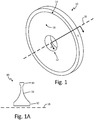
- Figs. 1 and 1A illustrate views of a hybrid disk.
- Fig. 1 shows a perspective view of hybrid disk 10
- Fig. 1A shows a radial cross-section of hybrid disk 10.
- Hybrid disk 10 includes bore region 12, rim region 14 and web region 16. During operation, hybrid disk 10 rotates about axis of rotation (centerline axis) 18. Bore region 12 is located radially inward of rim region 14 and web region 16 and rim region 14 is located radially outward of bore region 12 and web region 16.
- Bore region 12 is generally the central hub of hybrid disk 10 and can contain a through-hole for mounting hybrid disk 10 to a shaft.
- Web region 16 connects bore region 12 and rim region 14 so as to form a monolithic or one-piece hybrid rotor disk.
- the radially outer surface of hybrid disk 10 is located at rim region 14.
- Blade airfoils (not shown) are connected to hybrid disk 10 at the outer surface of rim region 14.
- hybrid disk 10 can have its greatest axial thickness (viewed left-to-right) at bore region 12. The region of least axial thickness can be at rim region 14 or a portion of web region 16 near rim region 14.
- hybrid disk 10 is formed from two substrates having differing material compositions and/or grain structures.
- the two substrates are forged or cast alloys.
- the two substrates are joined together to form hybrid disk 10 by inertia welding.
- the inertia welding process produces a solid-state joint between the two substrates via a metallurgical bond formed by a process where frictional heat is generated between a rotating substrate and a stationary substrate under an applied load. This bonding process minimizes solidification discontinuities and is essentially "self-cleaning" by removing any surface contaminants as the frayed metal flows out of the joint at the weld interface.
- the joint is located in a lower stress region of hybrid disk 10, for example, in web region 16.
- Rim substrate 22 is shaped (by forging, casting and/or machining) to approximate the finished shape of rim region 14 of hybrid disk 10. Rim substrate 22 is machined to have interface surface 25 where the metallurgical bond will be formed. Rim substrate 22 contains materials generally optimized for rim region 16 of hybrid disk 10. In some embodiments, rim substrate 22 contains cast, wrought and/or powder metallurgy alloys having high degrees of resistance to creep, rupture and cracking. Examples of suitable alloys for rim substrate 22 include PRM48, ME16, IN100, Alloy 10 and LSHR powder metallurgy alloys. In some examples, rim substrate 22 can include less than 0.06% carbon.
- Fig. 3 illustrates the metallurgical bond between bore substrate 20 and rim substrate 22 following inertia welding.
- inertia welding either the bore substrate 20 or the rim substrate 22 is held stationary while the other substrate is rotated about rotational axis 18.
- both bore substrate 20 and rim substrate 22 are oriented perpendicular to the rotational axis 18. While rotation is occurring, bore substrate 20 and rim substrate 22 are brought into contact with each other at respective interface surfaces 24 and 25. While rotation continues, interface surfaces 24 and 25 generate frictional heat that increases as pressure is applied in the direction of rotational axis 18.
- interface surfaces 24 and 25 of bore substrate 20 and rim substrate 22, respectively, where solid-state joint 26 is formed are angled relative to axis of rotation 18 (shown in Fig. 3 by angle ⁇ ). As shown, angle ⁇ is about 45°.
- the bond length (and resulting bond strength) of joint 26 is increased.
- the bonding surfaces of bore substrate 20 and rim substrate 22 are angled between 5° and 85° relative to axis of rotation 18. In further embodiments, the bonding surfaces of bore substrate 20 and rim substrate 22 are angled between 15° and 75° relative to axis of rotation 18.
- the bonding surfaces of bore substrate 20 and rim substrate 22 are angled between 30° and 60° relative to axis of rotation 18.
- Thermal and stress analyses of hybrid disk 10 can be performed to determine optimal angles of the bonding surfaces (interface surfaces 24 and 25, respectively) of bore substrate 20 and rim substrate 22.
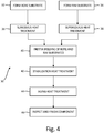
- Fig. 4 schematically illustrates one embodiment of method 30 for preparing hybrid disk 10.
- steps 32 and 34 of method 30 bore substrate 20 and rim substrate 22 are formed, respectively.
- steps 32 and 34 are followed by subsolvus heating treatment step 36 on bore substrate 20 and supersolvus heating treatment step 38 on rim substrate 22.
- step 40 bore substrate 20 and rim substrate 22 undergo inertia welding as described herein, resulting in the formation of solid-state joint 26 between bore substrate 20 and rim substrate 22.
- the welded bore substrate 20 and rim substrate 22 undergoes a stabilization heat treatment to relieve residual stress.
- step 44 the welded bore substrate 20 and rim substrate 22 undergoes an aging heat treatment to improve the component's material properties.
- step 46 the joined part is inspected and is then finish machined to form hybrid disk 10. Variations on the method illustrated in Fig. 4 are described above.
- Hybrid disk 10 prepared according to the method illustrated in Fig. 4 can include bore portion 12 having an average grain size between ASTM 11 and ASTM 9, rim portion 14 having an average grain size between ASTM 8 and ASTM 6, and web portion 16 located between bore portion 12 and rim portion 14.
- Web portion 16 includes solid-state joint 26 formed at interface surfaces 24 and 25 of bore substrate 20 and rim substrate 22, respectively. Solid-state joint 26 is angled between 5 degrees and 85 degrees relative to axis of rotation 18 of hybrid disk 10.
- a method of forming a hybrid component having an axis of rotation can include forming a first substrate comprising a first interface surface, the first substrate having a first average grain size; forming a second substrate comprising a second interface surface, the second substrate having a second average grain size different from the first average grain size; and inertia welding the first and second substrates together at a junction of the first and second interface surfaces to form a solid-state joint between the first and second substrates.
- the method of the preceding paragraph can optionally include, additionally and/or alternatively, any one or more of the following features, configurations and/or additional components:
- the joint can be angled between 5 degrees and 85 degrees relative to the axis of rotation of the hybrid component.
- Forming the first substrate can include heat treating the first substrate and machining the first interface surface.
- Forming the second substrate can include heat treating the second substrate and machining the second interface surface.
- the joint can be located between 50 percent and 80 percent of a radial distance from the axis of rotation of the hybrid disk to a radially outer edge of the rim substrate.
- the method can further include performing post-welding heat treatments on the hybrid disk and finish machining the hybrid disk.
- Forming the bore substrate can include heat treating the bore substrate and machining the first interface surface.
- Forming the rim substrate can include heat treating the rim substrate and machining the second interface surface.
- a hybrid disk can include a bore portion having an average grain size between ASTM 11 and ASTM 9; a rim portion having an average grain size between ASTM 8 and ASTM 6; and a web portion located between the bore portion and the rim portion, the web portion comprising a solid-state joint formed adjacent to a radially outer surface of the bore portion and a radially inner surface of the rim portion where the solid-state joint is angled between 5 degrees and 85 degrees relative to an axis of rotation of the hybrid disk.
Abstract
A method of forming a hybrid component having an axis of rotation includes forming a first substrate having a first interface surface and a first average grain size, forming a second substrate having a second interface surface and a second average grain size different from the first average grain size, and inertia welding the first and second substrates at a junction of the first and second interface surfaces to form a solid-state joint between the first and second substrates.
Description
- Traditionally, components of advanced engines are fabricated from a single material with uniform composition and microstructure. During operation, however, regions radially closer to a rotational component's axis of rotation generally operate at lower temperatures and higher stresses than the radially outer regions. A component fabricated from a single material does not possess optimized material properties for both the radially inner and outer regions to deal with the different radial stresses and temperatures in the part. As a result, the rotational component's performance can be severely limited. Presently, fabrication methods, such as solid-state joining or dual property heat treatments, can be used to produce a rotational component with improved location-specific properties. In the case of a rotational component having different materials (e.g., blades of one material and a rotor disk of another material), however, fabrication is very complex due to the additional processing steps required and typically results in a region of weakness near the joint and/or transition zone between the two different materials.
- To maximize performance, different regions of a rotational component should include different materials with location-optimized properties. For instance, regions radially closer to the axis of rotation of the rotational component benefit from greater low-temperature tensile strength, burst capability, and resistance to low-cycle fatigue, while regions at a greater radial distance from the component's centerline benefit from having greater high-temperature creep and rupture strength as well as increased defect tolerance.
- A method of forming a hybrid component having an axis of rotation includes forming a first substrate having a first interface surface and a first average grain size, forming a second substrate having a second interface surface and a second average grain size different from the first average grain size, and inertia welding the first and second substrates together at a junction of the first and second interface surfaces to form a solid-state joint between the first and second substrates.
- A method of forming a hybrid disk having an axis of rotation includes forming a bore substrate having a first interface surface and a first average grain size, and forming a rim substrate having a second interface surface and a second average grain size different from the first average grain size, and inertia welding the bore substrate and the rim substrate together at a junction of the first and second interface surfaces to form a solid-state joint between the bore substrate and the rim substrate.
- A hybrid disk includes a bore portion having an average grain size between ASTM 11 and ASTM 9, a rim portion having an average grain size between ASTM 8 and ASTM 6, and a web portion located between the bore portion and the rim portion. The web portion includes a solid-state joint formed adjacent to a radially outer surface of the bore portion and a radially inner surface of the rim portion. The solid-state joint is angled between 5 degrees and 85 degrees relative to an axis of rotation of the hybrid disk.
-
-
Fig. 1 is a view of a hybrid rotor disk. -
Fig. 1A is a radial cross-section view of the hybrid rotor disk ofFig. 1 . -
Fig. 2 is a view of an unjoined bore substrate and a rim substrate used to form a hybrid rotor disk. -
Fig. 3 is a view of the substrates following bonding. -
Fig. 4 is a schematic diagram of a method of producing a hybrid rotor disk. - The present disclosure relates generally to fabrication processes for the manufacture of components having regions of differing microstructures and/or composition. Frequently, operating conditions demand components containing different regions, of which differing material properties are needed to optimize performance (e.g., reduce fuel burn, increase overall engine efficiency). Examples where operating conditions may demand this invention are components of advanced engines. Typically, advanced engines operate more efficiently at higher temperatures and pressures.
- A hybrid component and a method of making the hybrid component are disclosed herein. One example of a hybrid component is a rotor disk for a compressor or turbine section of a gas turbine engine.
Figs. 1 and 1A illustrate views of a hybrid disk.Fig. 1 shows a perspective view ofhybrid disk 10 andFig. 1A shows a radial cross-section ofhybrid disk 10.Hybrid disk 10 includesbore region 12,rim region 14 andweb region 16. During operation,hybrid disk 10 rotates about axis of rotation (centerline axis) 18. Boreregion 12 is located radially inward ofrim region 14 andweb region 16 and rimregion 14 is located radially outward ofbore region 12 andweb region 16. Boreregion 12 is generally the central hub ofhybrid disk 10 and can contain a through-hole for mountinghybrid disk 10 to a shaft.Web region 16 connectsbore region 12 andrim region 14 so as to form a monolithic or one-piece hybrid rotor disk. The radially outer surface ofhybrid disk 10 is located atrim region 14. Blade airfoils (not shown) are connected tohybrid disk 10 at the outer surface ofrim region 14. As shown inFig. 1A ,hybrid disk 10 can have its greatest axial thickness (viewed left-to-right) atbore region 12. The region of least axial thickness can be atrim region 14 or a portion ofweb region 16 nearrim region 14. - As described herein,
hybrid disk 10 is formed from two substrates having differing material compositions and/or grain structures. In some cases, the two substrates are forged or cast alloys. The two substrates are joined together to formhybrid disk 10 by inertia welding. The inertia welding process produces a solid-state joint between the two substrates via a metallurgical bond formed by a process where frictional heat is generated between a rotating substrate and a stationary substrate under an applied load. This bonding process minimizes solidification discontinuities and is essentially "self-cleaning" by removing any surface contaminants as the frayed metal flows out of the joint at the weld interface. The joint is located in a lower stress region ofhybrid disk 10, for example, inweb region 16. By joining two substrates having differing material compositions and/or grain structures,hybrid disk 10 can be designed such that boreregion 12 andrim region 14 are each optimized for expected operating conditions and so the joint is placed in a lower stress region ofhybrid disk 10. -
Fig. 2 illustratesunjoined bore substrate 20 andrim substrate 22. As will be described in greater detail, boresubstrate 20 forms boreregion 12 and part ofweb region 16 ofhybrid disk 10 andrim substrate 22forms rim region 14 and part ofweb region 16.Bore substrate 20 is shaped (by forging, casting and/or machining) to approximate the finished shape ofbore region 12 ofhybrid disk 10.Bore substrate 20 is machined to haveinterface surface 24 where the metallurgical bond will be formed.Bore substrate 20 contains materials generally optimized forbore region 12 ofhybrid disk 10. In some embodiments,bore substrate 20 contains cast, wrought and/or powder metallurgy alloys having high degrees of tensile strength, low-temperature strength (resistance to low cycle fatigue) and burst capability. Examples of types of suitable alloys forbore substrate 20 include PRM48, ME16, IN100, IN1718, U720, U720li, ME3, Alloy 10 and low solvus, high refractory (LSHR) powder metallurgy alloys. In some examples,bore substrate 20 can include less than 0.06% carbon.Bore substrate 20 typically has a finer grain structure thanrim substrate 22. In some embodiments,bore substrate 20 has an average grain size of ASTM E112-13 ("ASTM") size 9 to 11.Bore substrate 20 can be heat treated before being used to formhybrid disk 10. For example, in one embodiment, boresubstrate 20 undergoes subsolvus heat treatment prior to inertia welding. Such heat treatment providesbore substrate 20 with properties generally desirable forbore region 12 ofhybrid disk 10. This pre-welding heat treatment can be performed before or after shaping ofbore substrate 20. -
Rim substrate 22 is shaped (by forging, casting and/or machining) to approximate the finished shape ofrim region 14 ofhybrid disk 10.Rim substrate 22 is machined to haveinterface surface 25 where the metallurgical bond will be formed.Rim substrate 22 contains materials generally optimized forrim region 16 ofhybrid disk 10. In some embodiments,rim substrate 22 contains cast, wrought and/or powder metallurgy alloys having high degrees of resistance to creep, rupture and cracking. Examples of suitable alloys forrim substrate 22 include PRM48, ME16, IN100,Alloy 10 and LSHR powder metallurgy alloys. In some examples,rim substrate 22 can include less than 0.06% carbon.Rim substrate 22 can contain a gamma-prime alloy having a higher solvus temperature than the alloy ofbore substrate 20.Rim substrate 22 typically has a coarser grain structure thanbore substrate 20. In some embodiments,rim substrate 22 has an average grain size of ASTM size 6 to 8.Rim substrate 22 can be heat treated before being used to formhybrid disk 10. For example, in one embodiment,rim substrate 22 undergoes supersolvus heat treatment prior to inertia welding so that grain growth occurs inrim substrate 22. Such heat treatment providesrim substrate 22 with properties generally desirable forrim region 14 ofhybrid disk 10. This pre-welding heat treatment can be performed before or after shaping ofrim substrate 22. -
Fig. 3 illustrates the metallurgical bond betweenbore substrate 20 andrim substrate 22 following inertia welding. During inertia welding, either thebore substrate 20 or therim substrate 22 is held stationary while the other substrate is rotated aboutrotational axis 18. During inertia welding, both boresubstrate 20 andrim substrate 22 are oriented perpendicular to therotational axis 18. While rotation is occurring, boresubstrate 20 andrim substrate 22 are brought into contact with each other at respective interface surfaces 24 and 25. While rotation continues, interface surfaces 24 and 25 generate frictional heat that increases as pressure is applied in the direction ofrotational axis 18. The necessary axial force, rotational speed and energy to form a metallurgical bond via inertia welding is dependent upon the surface areas of interface surfaces 24 and 25, as well as the material properties ofbore substrate 20 andrim substrate 22, including the substrates' respective size, mass, and material composition. After a sufficient duration of time has elapsed to form a metallurgical bond during which rotation is occurring and the substrates are forced into contact, the rotation speed is reduced to zero and solid-state joint 26 is formed. During inertia welding, metal from the frayed interface surfaces 24 and 25 flows out of the solid-state joint 26, thereby removing any surface contaminants.
Once solid-state joint 26 has been formed, the bondedbore substrate 20 andrim substrate 22 can be machined to remove remnants from the bond interface. Following machining, the part is inspected and then undergoes heat treatment cycles for stress relief and aging of the microstructures ofbore substrate 20 andrim substrate 22. These heat treatment steps relieve residual stress in the part and improve material properties ofbore substrate 20 andrim substrate 22. The post welding heat treatments do not affect the grain size of eitherbore substrate 20 orrim substrate 22. After the stabilization and aging heat treatments, the part is finish machined into the desired shape to producehybrid disk 10 and non-destructively evaluated. Alternatively, bore substrate and/orrim substrate 22 can undergo aging heat treatment prior to bonding. In this case, the post-welding heat treatment provides stress relief. - As shown in
Figs. 2 and 3 , interface surfaces 24 and 25 ofbore substrate 20 andrim substrate 22, respectively, where solid-state joint 26 is formed are angled relative to axis of rotation 18 (shown inFig. 3 by angle θ). As shown, angle θ is about 45°. By forming solid-state joint 26 at a non-zero and a non-90° angle relative to axis ofrotation 18, the bond length (and resulting bond strength) of joint 26 is increased. In some embodiments, the bonding surfaces ofbore substrate 20 andrim substrate 22 are angled between 5° and 85° relative to axis ofrotation 18. In further embodiments, the bonding surfaces ofbore substrate 20 andrim substrate 22 are angled between 15° and 75° relative to axis ofrotation 18. In still further embodiments, the bonding surfaces ofbore substrate 20 andrim substrate 22 are angled between 30° and 60° relative to axis ofrotation 18. Thermal and stress analyses ofhybrid disk 10 can be performed to determine optimal angles of the bonding surfaces (interface surfaces 24 and 25, respectively) ofbore substrate 20 andrim substrate 22. - Solid-state joint 26 can be formed at a relatively low stress region of
hybrid disk 10. A joint is often a "weaker" point within a component, and locating the joint in a region that is not subjected to excessive stress helps ensure that the joint holds during operation. Optimal locations for joint 26 withinhybrid disk 10 will depend on the operating conditions ofhybrid disk 10, as well as the compositions ofbore region 12 andrim region 14. As with the bonding angle, thermal and stress analyses ofhybrid disk 10 can be performed to determine optimal locations for joint 26. In some embodiments ofhybrid disk 10,web region 16 is a region subjected to lower stress than portions ofrim region 14, and joint 26 is located withinweb region 16. In some cases, joint 26 can be radially located between 50 percent and 80 percent of the radius of hybrid disk 10 (the distance from axis ofrotation 18 to the radially outer surface of rim region 14). -
Fig. 4 schematically illustrates one embodiment ofmethod 30 for preparinghybrid disk 10. Insteps method 30, boresubstrate 20 andrim substrate 22 are formed, respectively. In this embodiment, steps 32 and 34 are followed by subsolvusheating treatment step 36 onbore substrate 20 and supersolvusheating treatment step 38 onrim substrate 22. Instep 40, boresubstrate 20 andrim substrate 22 undergo inertia welding as described herein, resulting in the formation of solid-state joint 26 betweenbore substrate 20 andrim substrate 22. Instep 42, the weldedbore substrate 20 andrim substrate 22 undergoes a stabilization heat treatment to relieve residual stress. Instep 44, the weldedbore substrate 20 andrim substrate 22 undergoes an aging heat treatment to improve the component's material properties. Finally, instep 46, the joined part is inspected and is then finish machined to formhybrid disk 10. Variations on the method illustrated inFig. 4 are described above. - The steps described herein produce a hybrid disk having specific features.
Hybrid disk 10 prepared according to the method illustrated inFig. 4 can include boreportion 12 having an average grain size between ASTM 11 and ASTM 9,rim portion 14 having an average grain size between ASTM 8 and ASTM 6, andweb portion 16 located betweenbore portion 12 andrim portion 14.Web portion 16 includes solid-state joint 26 formed at interface surfaces 24 and 25 ofbore substrate 20 andrim substrate 22, respectively. Solid-state joint 26 is angled between 5 degrees and 85 degrees relative to axis ofrotation 18 ofhybrid disk 10. - As described herein,
hybrid disk 10 includes at least two different materials. One material is optimal forbore region 12 ofhybrid disk 10; the other material is optimal forrim region 14 ofhybrid disk 10. This allowshybrid disk 10 to have optimal materials at both boreregion 12 andrim region 14. - Inertia welding is used to join the two substrates at a point within the
web region 16 of thehybrid disk 10. This bonding process minimizes solidification discontinuities and is essentially "self-cleaning" by removing any surface contaminants as the frayed metal flows out of joint 26 during welding. Solid-state joint 26 is located in a relatively low stress area of theweb region 16. Prior to the formation of a metallurgical bond, each of the two substrates can be heat treated to produce the desired properties and grain structures (e.g., finer grain structure atbore region 12, coarser grain structure at rim region 14). This eliminates the need for post-bonding heat treatments that change the grain size of the different regions ofhybrid disk 10. - The following are non-exclusive descriptions of possible embodiments of the present invention.
- A method of forming a hybrid component having an axis of rotation can include forming a first substrate comprising a first interface surface, the first substrate having a first average grain size; forming a second substrate comprising a second interface surface, the second substrate having a second average grain size different from the first average grain size; and inertia welding the first and second substrates together at a junction of the first and second interface surfaces to form a solid-state joint between the first and second substrates.
- The method of the preceding paragraph can optionally include, additionally and/or alternatively, any one or more of the following features, configurations and/or additional components:
- The first substrate can form a bore region and a first web portion of a hybrid disk, and the second substrate can form a second web portion and a rim region of the hybrid disk such that the joint is located at a web region of the hybrid disk.
- The first average grain size can be finer than the second average grain size.
- The first average grain size can be between ASTM 11 and ASTM 9, and the second average grain size can be between ASTM 8 and ASTM 6.
- The joint can be angled between 5 degrees and 85 degrees relative to the axis of rotation of the hybrid component.
- The joint can be angled between 15 degrees and 75 degrees relative to the axis of rotation of the hybrid component.
- The joint can be located between 50 percent and 80 percent of a radial distance from the axis of rotation to a radially outer edge of the rim region formed by the second substrate.
- The method can further include performing post-welding heat treatments on the hybrid disk and finish machining the hybrid disk.
- The first substrate and the second substrate can include forged alloys.
- The first substrate and the second substrate can include cast alloys.
- Forming the first substrate can include heat treating the first substrate and machining the first interface surface.
- Forming the second substrate can include heat treating the second substrate and machining the second interface surface.
- A method of forming a hybrid disk having an axis of rotation can include forming a bore substrate having a first average grain size, the bore substrate comprising a first interface surface; forming a rim substrate having a second average grain size different from the first average grain size, the rim substrate comprising a second interface surface; and inertia welding the bore substrate and the rim substrate together at a junction of the first and second interface surfaces to form a solid-state joint between the bore substrate and the rim substrate.
- The method of the preceding paragraph can optionally include, additionally and/or alternatively, any one or more of the following features, configurations and/or additional components:
- The first average grain size can be between ASTM 11 and ASTM 9, and the second average grain size can be between ASTM 8 and ASTM 6.
- The joint can be angled between 5 degrees and 85 degrees relative to the axis of rotation of the hybrid disk.
- The joint can be located between 50 percent and 80 percent of a radial distance from the axis of rotation of the hybrid disk to a radially outer edge of the rim substrate.
- The method can further include performing post-welding heat treatments on the hybrid disk and finish machining the hybrid disk.
- Forming the bore substrate can include heat treating the bore substrate and machining the first interface surface.
- Forming the rim substrate can include heat treating the rim substrate and machining the second interface surface.
- A hybrid disk can include a bore portion having an average grain size between ASTM 11 and ASTM 9; a rim portion having an average grain size between ASTM 8 and ASTM 6; and a web portion located between the bore portion and the rim portion, the web portion comprising a solid-state joint formed adjacent to a radially outer surface of the bore portion and a radially inner surface of the rim portion where the solid-state joint is angled between 5 degrees and 85 degrees relative to an axis of rotation of the hybrid disk.
- While the invention has been described with reference to an exemplary embodiment(s), it will be understood by those skilled in the art that various changes may be made and equivalents may be substituted for elements thereof without departing from the scope of the invention. In addition, many modifications may be made to adapt a particular situation or material to the teachings of the invention without departing from the essential scope thereof. Therefore, it is intended that the invention not be limited to the particular embodiment(s) disclosed, but that the invention will include all embodiments falling within the scope of the appended claims.
Claims (15)
- A method of forming a hybrid component (10) having an axis of rotation (18), the method comprising:forming a first substrate (20) comprising a first interface surface (24), the first substrate (20) having a first average grain size;forming a second substrate (22) comprising a second interface surface (25), the second substrate (22) having a second average grain size different from the first average grain size; andinertia welding the first and second substrates (20, 22) together at a junction of the first and second interface surfaces (24, 25) to form a solid-state joint (26) between the first and second substrates (20, 22).
- The method of claim 1, wherein the first substrate (20) forms a bore region (12) and a first web portion of a hybrid disk (10), and wherein the second substrate (22) forms a second web portion and a rim region (14) of the hybrid disk (10) such that the joint (26) is located at a web region (16) of the hybrid disk (10).
- The method of claim 2, wherein the joint (26) is located between 50 percent and 80 percent of a radial distance from the axis of rotation (18) to a radially outer edge of the rim region (14) formed by the second substrate (22).
- The method of claim 2 or 3, further comprising:performing post-welding heat treatments on the hybrid disk (10); andfinish machining the hybrid disk (10).
- The method of any preceding claim, wherein the joint (26) is angled between 5 degrees and 85 degrees relative to the axis of rotation (18) of the hybrid component (10),
wherein, optionally, the joint (26) is angled between 15 degrees and 75 degrees relative to the axis of rotation (18) of the hybrid component (10). - The method of any preceding claim, wherein the first substrate (20) and the second substrate (22) comprise forged alloys, or cast alloys.
- The method of any preceding claim, wherein forming the first substrate (20) comprises:heat treating the first substrate (20); andmachining the first interface surface (24);wherein, optionally forming the second substrate (22) comprises:heat treating the second substrate (22); andmachining the second interface surface (25).
- The method of any preceding claim, wherein the first average grain size is finer than the second average grain size.
- A method of forming a hybrid disk (10) having an axis of rotation (18), the method comprising:forming a bore substrate (20) having a first average grain size, the bore substrate (20) comprising a first interface surface (24);forming a rim substrate (22) having a second average grain size different from the first average grain size, the rim substrate (22) comprising a second interface surface (25); andinertia welding the bore substrate (20) and the rim substrate (22) together at a junction of the first and second interface surfaces (24, 25) to form a solid-state joint (26) between the bore substrate (20) and the rim substrate (22).
- The method of claim 8 or 9, wherein the first average grain size is between ASTM 11 and ASTM 9, and wherein the second average grain size is between ASTM 8 and ASTM 6.
- The method of claim 9 or 10, wherein the joint (26) is angled between 5 degrees and 85 degrees relative to the axis of rotation (18) of the hybrid disk (10).
- The method of any of claims 9 to 11, wherein the joint (26) is located between 50 percent and 80 percent of a radial distance from the axis of rotation (18) of the hybrid disk (10) to a radially outer edge of the rim substrate (22).
- The method of any of claims 9 to 12, further comprising:performing post-welding heat treatments on the hybrid disk (10); andfinish machining the hybrid disk (10).
- The method of any of claims 9 to 13, wherein forming the bore substrate (20) comprises:heat treating the bore substrate (20); andmachining the first interface surface (24),wherein, optionally forming the rim substrate (22) comprises:heat treating the rim substrate (22); andmachining the second interface surface (25).
- A hybrid disk (10) comprising:a bore portion (12) having an average grain size between ASTM 11 and ASTM 9;a rim portion (14) having an average grain size between ASTM 8 and ASTM 6; anda web portion (16) located between the bore portion (12) and the rim portion (14), the web portion (16) comprising a solid-state joint (26) formed adjacent to a radially outer surface of the bore portion (12) and a radially inner surface of the rim portion (14), wherein the solid-state joint (26) is angled between 5 degrees and 85 degrees relative to an axis of rotation (18) of the hybrid disk (10).
Applications Claiming Priority (1)
| Application Number | Priority Date | Filing Date | Title |
|---|---|---|---|
| US15/292,753 US20180105914A1 (en) | 2016-10-13 | 2016-10-13 | Hybrid component and method of making |
Publications (1)
| Publication Number | Publication Date |
|---|---|
| EP3309264A1 true EP3309264A1 (en) | 2018-04-18 |
Family
ID=59677004
Family Applications (1)
| Application Number | Title | Priority Date | Filing Date |
|---|---|---|---|
| EP17185404.5A Withdrawn EP3309264A1 (en) | 2016-10-13 | 2017-08-08 | Hybrid component and method of making |
Country Status (3)
| Country | Link |
|---|---|
| US (1) | US20180105914A1 (en) |
| EP (1) | EP3309264A1 (en) |
| JP (1) | JP2018062934A (en) |
Cited By (1)
| Publication number | Priority date | Publication date | Assignee | Title |
|---|---|---|---|---|
| EP3421622A1 (en) * | 2017-06-26 | 2019-01-02 | United Technologies Corporation | Solid-state welding of coarse grain powder metallurgy nickel-based superalloys |
Families Citing this family (3)
| Publication number | Priority date | Publication date | Assignee | Title |
|---|---|---|---|---|
| US10309232B2 (en) * | 2012-02-29 | 2019-06-04 | United Technologies Corporation | Gas turbine engine with stage dependent material selection for blades and disk |
| US20180371924A1 (en) * | 2017-06-27 | 2018-12-27 | Florida Turbine Technologies, Inc. | Additively Manufactured Blisk with Optimized Microstructure for Small Turbine Engines |
| US11549374B2 (en) * | 2020-02-18 | 2023-01-10 | Raytheon Technologies Corporation | Gas turbine rotor component and method of manufacture |
Citations (5)
| Publication number | Priority date | Publication date | Assignee | Title |
|---|---|---|---|---|
| EP1526252A2 (en) * | 2003-10-21 | 2005-04-27 | General Electric Company | Tri-property rotor assembly of a turbine engine and method for its preparation |
| EP2353750A1 (en) * | 2010-02-05 | 2011-08-10 | General Electric Company | Welding process and component produced therefrom |
| EP2359975A1 (en) * | 2010-02-19 | 2011-08-24 | General Electric Company | Welding process and component formed thereby |
| EP2520395A2 (en) * | 2011-05-04 | 2012-11-07 | General Electric Company | Components and processes of producing components with regions having different grain structures |
| EP2530181A1 (en) * | 2011-06-03 | 2012-12-05 | General Electric Company | Components and processes of producing components with regions having different grain structures |
-
2016
- 2016-10-13 US US15/292,753 patent/US20180105914A1/en not_active Abandoned
-
2017
- 2017-08-08 EP EP17185404.5A patent/EP3309264A1/en not_active Withdrawn
- 2017-08-10 JP JP2017155676A patent/JP2018062934A/en active Pending
Patent Citations (5)
| Publication number | Priority date | Publication date | Assignee | Title |
|---|---|---|---|---|
| EP1526252A2 (en) * | 2003-10-21 | 2005-04-27 | General Electric Company | Tri-property rotor assembly of a turbine engine and method for its preparation |
| EP2353750A1 (en) * | 2010-02-05 | 2011-08-10 | General Electric Company | Welding process and component produced therefrom |
| EP2359975A1 (en) * | 2010-02-19 | 2011-08-24 | General Electric Company | Welding process and component formed thereby |
| EP2520395A2 (en) * | 2011-05-04 | 2012-11-07 | General Electric Company | Components and processes of producing components with regions having different grain structures |
| EP2530181A1 (en) * | 2011-06-03 | 2012-12-05 | General Electric Company | Components and processes of producing components with regions having different grain structures |
Cited By (3)
| Publication number | Priority date | Publication date | Assignee | Title |
|---|---|---|---|---|
| EP3421622A1 (en) * | 2017-06-26 | 2019-01-02 | United Technologies Corporation | Solid-state welding of coarse grain powder metallurgy nickel-based superalloys |
| US10718041B2 (en) | 2017-06-26 | 2020-07-21 | Raytheon Technologies Corporation | Solid-state welding of coarse grain powder metallurgy nickel-based superalloys |
| EP3995594A1 (en) * | 2017-06-26 | 2022-05-11 | Raytheon Technologies Corporation | Solid-state welding of coarse grain powder metallurgy nickel-based superalloys |
Also Published As
| Publication number | Publication date |
|---|---|
| US20180105914A1 (en) | 2018-04-19 |
| JP2018062934A (en) | 2018-04-19 |
Similar Documents
| Publication | Publication Date | Title |
|---|---|---|
| US8636195B2 (en) | Welding process and component formed thereby | |
| EP3421622B1 (en) | Solid-state welding of coarse grain powder metallurgy nickel-based superalloys | |
| EP3309264A1 (en) | Hybrid component and method of making | |
| EP3308900A1 (en) | Hybrid component and method of making | |
| US8146795B2 (en) | Method of friction welding | |
| US20180209280A1 (en) | Bladed disc and method of manufacturing the same | |
| US8480368B2 (en) | Welding process and component produced therefrom | |
| CN108343475B (en) | Bladed disk and method for manufacturing a bladed disk | |
| JP2011501019A (en) | Manufacturing method of blisk or bling, component manufactured by the manufacturing method, and turbine blade | |
| US20120301307A1 (en) | Friction Welding of Titanium Aluminide Turbine to Titanium Alloy Shaft | |
| US7841506B2 (en) | Method of manufacture of dual titanium alloy impeller | |
| US8187724B2 (en) | Method of manufacture of a dual alloy impeller | |
| US7370787B2 (en) | Compressor rotor and method for making | |
| US20190184489A1 (en) | Method for joining components and device | |
| US20080000558A1 (en) | Friction welding | |
| US20110142653A1 (en) | Two piece impeller | |
| US20190376396A1 (en) | Turbine blisk and process of making | |
| US9333589B2 (en) | Component and method for joining metal elements |
Legal Events
| Date | Code | Title | Description |
|---|---|---|---|
| PUAI | Public reference made under article 153(3) epc to a published international application that has entered the european phase |
Free format text: ORIGINAL CODE: 0009012 |
|
| AK | Designated contracting states |
Kind code of ref document: A1 Designated state(s): AL AT BE BG CH CY CZ DE DK EE ES FI FR GB GR HR HU IE IS IT LI LT LU LV MC MK MT NL NO PL PT RO RS SE SI SK SM TR |
|
| AX | Request for extension of the european patent |
Extension state: BA ME |
|
| STAA | Information on the status of an ep patent application or granted ep patent |
Free format text: STATUS: THE APPLICATION IS DEEMED TO BE WITHDRAWN |
|
| 18D | Application deemed to be withdrawn |
Effective date: 20181019 |