EP3309065A1 - Method for influencing cross-flow instabilities in a fluid flow body and flow body system - Google Patents
Method for influencing cross-flow instabilities in a fluid flow body and flow body system Download PDFInfo
- Publication number
- EP3309065A1 EP3309065A1 EP16193326.2A EP16193326A EP3309065A1 EP 3309065 A1 EP3309065 A1 EP 3309065A1 EP 16193326 A EP16193326 A EP 16193326A EP 3309065 A1 EP3309065 A1 EP 3309065A1
- Authority
- EP
- European Patent Office
- Prior art keywords
- flow
- heating
- flow body
- points
- heating points
- Prior art date
- Legal status (The legal status is an assumption and is not a legal conclusion. Google has not performed a legal analysis and makes no representation as to the accuracy of the status listed.)
- Granted
Links
- 239000012530 fluid Substances 0.000 title claims abstract description 32
- 238000000034 method Methods 0.000 title claims abstract description 19
- 238000010438 heat treatment Methods 0.000 claims abstract description 181
- 230000001629 suppression Effects 0.000 claims description 4
- 230000008878 coupling Effects 0.000 description 5
- 238000010168 coupling process Methods 0.000 description 5
- 238000005859 coupling reaction Methods 0.000 description 5
- 230000000694 effects Effects 0.000 description 4
- 230000015572 biosynthetic process Effects 0.000 description 3
- 230000002860 competitive effect Effects 0.000 description 3
- 238000013461 design Methods 0.000 description 3
- 238000011161 development Methods 0.000 description 3
- 230000018109 developmental process Effects 0.000 description 3
- 238000007664 blowing Methods 0.000 description 2
- 230000002349 favourable effect Effects 0.000 description 2
- 230000003321 amplification Effects 0.000 description 1
- 230000002238 attenuated effect Effects 0.000 description 1
- 238000004140 cleaning Methods 0.000 description 1
- 238000010276 construction Methods 0.000 description 1
- 230000001419 dependent effect Effects 0.000 description 1
- 238000005485 electric heating Methods 0.000 description 1
- 238000012423 maintenance Methods 0.000 description 1
- 239000002184 metal Substances 0.000 description 1
- 238000003199 nucleic acid amplification method Methods 0.000 description 1
- 230000001737 promoting effect Effects 0.000 description 1
- 238000012546 transfer Methods 0.000 description 1
- 230000007306 turnover Effects 0.000 description 1
Images


Classifications
-
- B—PERFORMING OPERATIONS; TRANSPORTING
- B64—AIRCRAFT; AVIATION; COSMONAUTICS
- B64C—AEROPLANES; HELICOPTERS
- B64C23/00—Influencing air flow over aircraft surfaces, not otherwise provided for
- B64C23/06—Influencing air flow over aircraft surfaces, not otherwise provided for by generating vortices
- B64C23/065—Influencing air flow over aircraft surfaces, not otherwise provided for by generating vortices at the wing tips
-
- B—PERFORMING OPERATIONS; TRANSPORTING
- B64—AIRCRAFT; AVIATION; COSMONAUTICS
- B64C—AEROPLANES; HELICOPTERS
- B64C23/00—Influencing air flow over aircraft surfaces, not otherwise provided for
- B64C23/005—Influencing air flow over aircraft surfaces, not otherwise provided for by other means not covered by groups B64C23/02 - B64C23/08, e.g. by electric charges, magnetic panels, piezoelectric elements, static charges or ultrasounds
-
- B—PERFORMING OPERATIONS; TRANSPORTING
- B64—AIRCRAFT; AVIATION; COSMONAUTICS
- B64C—AEROPLANES; HELICOPTERS
- B64C23/00—Influencing air flow over aircraft surfaces, not otherwise provided for
- B64C23/06—Influencing air flow over aircraft surfaces, not otherwise provided for by generating vortices
-
- B—PERFORMING OPERATIONS; TRANSPORTING
- B64—AIRCRAFT; AVIATION; COSMONAUTICS
- B64C—AEROPLANES; HELICOPTERS
- B64C9/00—Adjustable control surfaces or members, e.g. rudders
- B64C9/14—Adjustable control surfaces or members, e.g. rudders forming slots
- B64C9/16—Adjustable control surfaces or members, e.g. rudders forming slots at the rear of the wing
- B64C9/20—Adjustable control surfaces or members, e.g. rudders forming slots at the rear of the wing by multiple flaps
-
- B—PERFORMING OPERATIONS; TRANSPORTING
- B64—AIRCRAFT; AVIATION; COSMONAUTICS
- B64C—AEROPLANES; HELICOPTERS
- B64C2230/00—Boundary layer controls
- B64C2230/10—Boundary layer controls by influencing fluid flow by heating using other means than combustion
-
- Y—GENERAL TAGGING OF NEW TECHNOLOGICAL DEVELOPMENTS; GENERAL TAGGING OF CROSS-SECTIONAL TECHNOLOGIES SPANNING OVER SEVERAL SECTIONS OF THE IPC; TECHNICAL SUBJECTS COVERED BY FORMER USPC CROSS-REFERENCE ART COLLECTIONS [XRACs] AND DIGESTS
- Y02—TECHNOLOGIES OR APPLICATIONS FOR MITIGATION OR ADAPTATION AGAINST CLIMATE CHANGE
- Y02T—CLIMATE CHANGE MITIGATION TECHNOLOGIES RELATED TO TRANSPORTATION
- Y02T50/00—Aeronautics or air transport
- Y02T50/10—Drag reduction
Definitions
- the present invention relates to a method for influencing crossflow instabilities on a flow body and to a flow body system.
- transverse flows which are directed transversely to the flow direction, in which the fluid flow flows against the flow body, generally occur. Transverse flows can occur in particular in the case of an inflow of the flow body in a flow direction which has a directional component directed along the front edge. Furthermore, transverse flows form as a result of pressure gradients which, for example, result from different cross-sectional profiles of the flow body which arise along the front edge.
- the crossflows cause crossflow instabilities in the fluid flow that are amplified and ultimately cause a laminar-turbulent turnaround in the fluid flow.
- a laminar boundary layer In certain cases, such as in the wing tip area very slender wings, is a laminar boundary layer however, undesirable. In these cases, therefore, there is a need to accentuate the laminar-turbulent envelope conveying cross-flow instabilities.
- a method for influencing crossflow instabilities on a flow body is provided.
- the flow body is flown against a fluid flow at a leading edge.
- heating of discrete heating points takes place, which are arranged at a distance from one another with respect to a depth direction of the flow body which is transverse to the front edge, downstream of the leading edge on the flow surface of the flow body and along the front edge.
- instabilities into the flow for influencing the growth of cross flow instabilities by heating the flow surface in a plurality of small, separate and spaced-apart surface regions.
- the influencing of the growth of the cross-flow instabilities can thereby be used for a suppression, ie a hindrance to the growth, or an intensification of a laminar-turbulent envelope promoting cross-flow instabilities.
- a fluid flow flowing over the flow surface of the flow body is heated at the hot heating points, whereby a local density change and a viscosity change of the fluid flow in the region of the heating points is achieved.
- the heating of the heating points by means of a thermally coupled to this electric heater.
- the heating stations are therefore heated by means of electrical energy.
- An electric heating of the heating is structurally feasible in a simple manner and with low weight.
- the discrete heating points are formed as discrete surface areas of the flow surface of the flow body, which at a predetermined distance, which is smaller than a wavelength of a most amplified under predetermined flow conditions mode of suppression of cross-flow instability to each other are arranged.
- predetermined flow conditions of the flow body can be determined depending on the geometry of the flow body, the most excited modes of Querstrominstabilticianen for example by applying the linear stability theory to the fluid flow descriptive boundary layer equations.
- the heating points are therefore preferably at a distance from one another which is smaller than the wavelength of a crossflow instability to be suppressed. In this way, the growth of the crossflow instability to be suppressed is suppressed particularly effectively.
- the heating points are arranged at a distance to one another in a range between 1 mm and 10 mm. In this distance range is advantageously a very good attenuation of cross-flow instabilities for a wide range of possible flow boundary conditions.
- the heating points are arranged periodically along the front edge, ie with the same distance from one another.
- the discrete heating points are preferably formed as discrete surface areas of the flow surface of the flow body, the heating points having an extension along the leading edge which is between 10 percent and 70 percent of the spacing of the heating locations. Accordingly, the heating points have a length which is smaller than the distance between the heating points to each other. In the range of length between 10 percent and 70 percent of the distance of the heating sites from each other is advantageously achieved a strong influence effect of the growth of cross-flow instabilities for a wide range of possible flow boundary conditions.
- the length of the heating points between 20 percent and 50 percent of the spacing of the heating points to each other.
- a strong influencing effect of the growth of cross-flow instabilities is advantageously achieved for a sufficiently large range of possible flow boundary conditions with little design effort
- the discrete heating points are formed as circular, elliptical, rectangular, polygonal or similar discrete surface areas of the flow surface of the flow body.
- Circular heating points offer the particular advantage that they are structurally easy to implement.
- a flow body system includes a flow body having a flow surface forming a leading edge of the flow body and a heater thermally conductive to heating surfaces of the flow surface for heating the heating points.
- the heating points are spaced relative to each other with respect to a depth direction extending transversely to the leading edge and along the leading edge.
- the flow body system thus has a flow body with a front edge provided for the flow of fluid flow. Furthermore, heatable surface areas are provided as heating points on a flow surface of the flow body. These can be heated by means of a heating device and arranged opposite the leading edge with respect to an intended inflow direction downstream of the leading edge. In particular, the heating points are spaced from one another along a longitudinal direction defined by the front edge, so that the heating points form a row running along the front edge. The heating points are thus spaced from each other in a direction transverse to a direction of flow direction of the flow body extending transverse flow direction.
- the heating points which are thermally coupled to the heating device, can be heated by means of the heating device, as a result of which, in a simple and efficient manner, targeted competition instabilities can be introduced into a fluid flow flowing around the flow body.
- targeted competition instabilities can be introduced into a fluid flow flowing around the flow body.
- only a thermally coupled to the flow surface heating device is necessary to generate the competition instabilities.
- the flow body system according to the invention has an improved operational reliability. Furthermore, the energy needed to generate the competitive vortex is very low.
- thermal coupling between the heating points and the heater is herein generally understood heat transfer from the heater to the flow surface of the flow body.
- the heating device has a number of heating elements corresponding to the number of heating elements. Each heating station is assigned a heating element. As a result, the reliability of the flow body system is increased.
- the heating elements can each be arranged on the side of an inner surface of the flow body oriented opposite to the flow surface. Accordingly, the heating elements are housed inside the flow body. In this way, aerodynamically disadvantageous bumps on the flow surface are avoided.
- the heating elements are formed by electrical heating resistors.
- Electrical heating resistors for example in the form of heating coils, are extremely inexpensive and can be easily mounted on the flow body. Furthermore, these elements offer the advantage that they have a high heating efficiency. This makes it possible to realize a structurally simple construction of the flow body system with very low weight.
- the flow body system additionally has a functionally coupled to the heating elements control means by means of which the heating elements are individually actuated.
- the control device is therefore designed to put each of the heating elements independently of the other heating elements in a heating state. Thereby, the distance between adjacent located in a heating state heating points can be changed and thus the introduction of competition vortexes in a fluid flow can be flexibly adapted to the flow conditions. For example, this controllability of the heating elements allows both the attenuation and the amplification of cross-flow instabilities. This achieves great flexibility in flow control.
- the heating elements are contacted to the opposite to the flow surface oriented inner surface of the flow body thermally conductive.
- the heating elements are arranged in formed in the flow body recesses and terminate flush with the flow surface.
- a heating unit of the heating element itself or a thermally conductively connected thereto heat conduction member may be arranged in the recess.
- the heating element forms the part of the flow surface of the flow body which corresponds to the heating point.
- the heating points are formed as discrete surface areas of the flow surface of the flow body, wherein the heating points an extension along the leading edge, which is between 10 percent and 70 percent of the spacing of the heating points to each other. In the region of the length between 10 percent and 70 percent of the distance of the heating points to each other, a strong influence effect of the growth of crossflow instabilities is advantageously achieved for a wide range of possible flow boundary conditions.
- the length of the heating points between 20 percent and 50 percent of the spacing of the heating points to each other.
- a strong influencing effect of the growth of cross-flow instabilities is advantageously achieved for a sufficiently large range of possible flow boundary conditions with little design effort.
- the heating points are arranged at a distance to one another in a range between 1 mm and 10 mm. In this distance range is advantageously a very good attenuation of cross-flow instabilities for a wide range of possible flow boundary conditions.
- the heating points are arranged periodically along the front edge, ie with the same distance from one another.
- the discrete heating points are formed as circular, elliptical, rectangular, polygonal or similar discrete surface areas of the flow surface of the flow body.
- Circular heating points offer the particular advantage that they are structurally easy to implement.
- a bore may be formed in the flow body into which a rod-shaped portion of a heating element of the heater is inserted.
- the flow body system according to the invention is particularly suitable for carrying out the method described above.
- Features and advantages disclosed in connection with the method thus also apply analogously to the flow body system and vice versa.
- a wing for an aircraft having a flow body system according to any of the embodiments described above.
- the flow body of the Flow body system preferably forms a wing component of the group consisting of leading edge flap, trailing edge flap, wing main body, tail, elevator, fin and rudder.
- direction indications and axes in particular to directions and axes which relate to the course of physical structures, herein is understood to mean a course of an axis, a direction or a structure "along" another axis, direction or structure, that these, in particular the tangents resulting in a respective position of the structures each extend at an angle of less than 45 degrees, preferably less than 30 degrees, and particularly preferably parallel to one another.
- a progression of an axis, a direction or a structure is understood to be "transverse" to another axis, direction or structure, that in particular, the tangents resulting in a respective position of the structures each extend at an angle of greater than or equal to 45 degrees, preferably greater than or equal to 60 degrees and particularly preferably perpendicular to one another.
- the length of a shortest possible connecting line between two directly adjacent heating points is understood herein.
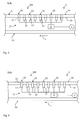
- the Fig. 1 and 2 show schematically and by way of example a flow body 1 of a flow body system 100.
- the flow body 1 has an outer contour of the flow body 1 defining flow surface 1a.
- the flow surface 1a forms a leading edge 2 of the flow body 1 which is intended for the flow.
- the front edge 2 divides the flow surface 1 a in a pressure side 1 d and a suction side 1 s.
- the flow body 1 is designed as an elongated body, wherein the front edge 2 of the flow body 1 extends in a longitudinal direction L of the flow body 1.
- 1 heating points 10 are provided on the flow surface 1 a of the flow body.
- the heating points 10 can be heated by means of a heating device 11 which is thermally coupled to the heating points 10 of the flow surface 1 a and hereinafter referred to as 3 and 4 will be described in more detail.
- the heating points 10 are heated by means of the heating device 11.
- the fluid flow flowing over the flow surface 1a is heated at the hot heating points 10, whereby a local density change and a viscosity change of the fluid flow in the area of the heating points 10 are achieved becomes.
- at each heating point 10 located in one heated state is generated in the flow direction S of the fluid flow increasing competition or instabilities.
- the formation and growth of competition vortex suppresses or promotes the growth of undesirable cross flow instabilities.
- a plurality of heating points 10 along the front edge 2 of the flow body 1 are provided.
- the heating points 10 with respect to a transverse to the front edge 2 extending depth direction D to the front edge 2 are arranged spaced.
- the heating points 10 are mutually arranged with respect to the longitudinal direction L at a distance d10.
- the distance d10 preferably lies in a range between 1 mm and 10 mm and, in particular, between two heating points 10 located adjacent to the longitudinal direction L, can be the same for all heating points 10, as in FIG Fig. 2 is shown by way of example.
- the Fig. 1 and 2 each show one along the longitudinal direction L extending row of heating points 10.
- heating points 10 may be provided in the depth direction D.
- heating points 10 provided on the suction side 1s of the flow body 1 are shown by way of example.
- the heating points 10 may also be provided on the pressure side 1d of the flow body 1.
- the discrete heating points 10 are preferably formed as circular discrete surface areas of the flow surface 1 a of the flow body 1, as shown by way of example in FIGS Fig. 1 and 2 is shown.
- the heating points 10 have an extension l10 along the front edge 2, which is between 10 percent and 70 percent, in particular between 20 percent and 50 percent of the spacing of the heating points 10 to each other.
- the extent l10 or the longitudinal extension of the heating points is thus in particular between 10 percent and 70 percent, preferably between 20 percent and 50 percent of the distance d10.
- the extent l10 corresponds to the circle diameter.
- the flow body system 100 further comprises a thermally conductive coupled to the heating points 10 heater 11 for heating the heating points 10.
- the flow body 1 is preferably formed as a hollow body with an opposite to the flow surface 1 a oriented inner surface 1 b.
- the Heating device 11 can be arranged in particular on the side of the inner surface 1b or in the interior of the flow body 1, as in the 3 and 4 is shown by way of example.
- the heating device 11 preferably has a number of heating elements 12 corresponding to the number of heating points 10.
- the heating elements 12 are in the 3 and 4 each shown schematically and may be formed in particular by electrical heating resistors, which are connectable to an electrical voltage source V.
- Fig. 3 shows a possibility of thermal coupling of the heating elements 12 to the heating points 10 by contacting the heating elements 12 to the inner surface 1 b of the flow body.
- 1 Fig. 3 shows an example of a realization of the thermal coupling by direct contacting of the heating elements 12 to the inner surface 1b of the flow body 1.
- the heat-generating heating units (not shown) of the heating elements 12 by means of heat conduction parts (not shown), for example, metal plate or the like (not shown) are thermally conductive contacted with the inner surface 1b.
- the heating points 10 are indicated schematically as dashed lines.
- Fig. 4 shows a further preferred possibility of thermal coupling of the heating elements 12 to the heating points 10.
- the heating elements 12 are arranged in between the flow surface 1a and the inner surface 1b extending recesses 13 and inserted into this.
- the heating elements 12 terminate flush with the flow surface 1a, so that the end faces of the heating elements 12 each form the heating point 10 and thus a part of the flow surface 1a.
- the 3 and 4 also show an optional control device 15 of the flow body system 100.
- the control device 15 is functionally coupled to the heating elements 12 and provided for the individual actuation of individual heating elements 12.
- the control device 15 is designed to switch on an electrical voltage generated by the voltage source V to the individual heating elements 12 and thus to switch them into a heating state.
- individual heating elements 12 or groups of heating elements 12 can each be placed in a heating state and thus the distance between two heated heating points 10 can be adjusted.
- different modes of the cross-current instabilities to be suppressed are attenuated or amplified. This can be realized by controlling the heating state of the heating points 10, a flexible flow control.
- Fig. 5 1 shows an advantageous use of the flow body system 100 described above in a wing 200 of an aircraft 201.
- the flow body 1 can in this case in particular comprise a leading edge flap 202, a trailing edge flap 203, a wing main body 204, a tail 205, an elevator 206, a fin 207 or a rudder (not shown).
Abstract
Die vorliegende Erfindung beschreibt ein Verfahren zur Beeinflussung von Querstrominstabilitäten an einem Strömungskörper (1), welcher an einer Vorderkante (2) mit einer Fluidströmung angeströmt wird, wobei ein Erhitzen von diskreten Heizstellen (10) erfolgt, welche stromabwärts der Vorderkante (2) an der Strömungsoberfläche (1a) des Strömungskörpers (1) und entlang der Vorderkante (2) beabstandet zueinander angeordnet sind. Dadurch werden die Querstrominstabilitäten beeinflussende Konkurrenzwirbel in der Fluidströmung erzeugt. Ferner ist ein Strömungskörpersystem (100) beschrieben.The present invention describes a method for influencing cross-flow instabilities on a flow body (1), which is flowed against a leading edge (2) with a fluid flow, wherein heating of discrete heating points (10) takes place, which downstream of the leading edge (2) on the Flow surface (1 a) of the flow body (1) and along the front edge (2) are arranged spaced from each other. As a result, competing vortexes influencing the instability of the flow stream are generated in the fluid flow. Further, a flow body system (100) is described.
Description
Die vorliegende Erfindung betrifft ein Verfahren zur Beeinflussung von Querstrominstabilitäten an einem Strömungskörper sowie ein Strömungskörpersystem.The present invention relates to a method for influencing crossflow instabilities on a flow body and to a flow body system.
Obwohl in vielfältigen Anwendungen von umströmten Oberflächen bzw. Strömungskörpern verwendbar, werden die vorliegende Erfindung sowie die ihr zugrunde liegende Problematik in Bezug auf umströmte Oberflächen von Luftfahrzeugen näher erläutert.Although usable in a variety of applications of flow-around surfaces or flow bodies, the present invention and the problems underlying it are described in relation to the flow-around surfaces of aircraft closer.
Um einen Strömungskörper mit geringem Strömungswiderstand zu realisieren, wird häufig versucht, eine den Strömungskörper umströmende Fluidströmung derart zu beeinflussen, dass ein laminar-turbulenter Umschlag der Strömung verhindert oder erst möglichst weit stromabwärts einer angeströmten Vorderkante des Strömungskörpers auftritt. In technischen Anwendungen von Strömungskörpern, wie beispielsweise Flugzeugflügeln, treten in der Regel Querströmungen auf, die quer zu der Strömungsrichtung gerichtet sind, in welcher die Fluidströmung den Strömungskörper anströmt. Querströmungen können insbesondere bei einer Anströmung des Strömungskörpers in einer Strömungsrichtung, welche eine entlang der Vorderkante gerichtete Richtungskomponente aufweist, auftreten. Weiterhin bilden sich Querströmungen infolge von Druckgradienten, welche beispielsweise aus unterschiedlichen sich entlang der Vorderkante ergebenden Querschnittsprofilen des Strömungskörpers resultieren. Die Querströmungen verursachen Querstrominstabilitäten in der Fluidströmung, welche verstärkt werden und letztlich einen laminar-turbulenten Umschlag der Fluidströmung verursachen. In bestimmten Fällen, wie beispielsweise im Flügelspitzenbereich sehr schlanker Flügel, ist eine laminare Grenzschicht hingegen unerwünscht. In diesen Fällen besteht daher ein Bedarf zur Anfachung von den laminar-turbulenten Umschlag befördernden Querstrominstabilitäten.In order to realize a flow body with low flow resistance, it is frequently attempted to influence a fluid flow flowing around the flow body in such a way that a laminar-turbulent turnoff prevents the flow or only occurs as far downstream as possible from a flowed leading edge of the flow body. In technical applications of flow bodies, such as aircraft wings, transverse flows, which are directed transversely to the flow direction, in which the fluid flow flows against the flow body, generally occur. Transverse flows can occur in particular in the case of an inflow of the flow body in a flow direction which has a directional component directed along the front edge. Furthermore, transverse flows form as a result of pressure gradients which, for example, result from different cross-sectional profiles of the flow body which arise along the front edge. The crossflows cause crossflow instabilities in the fluid flow that are amplified and ultimately cause a laminar-turbulent turnaround in the fluid flow. In certain cases, such as in the wing tip area very slender wings, is a laminar boundary layer however, undesirable. In these cases, therefore, there is a need to accentuate the laminar-turbulent envelope conveying cross-flow instabilities.
Üblicherweise wird zur Verbesserung des laminar-turbulenten Umschlagverhaltens versucht, das Anwachsen der Querstrominstabilitäten durch gezieltes Einbringen von Strömungsinstabilitäten in Form eines künstlichen, aktiv erzeugten Wirbelsystems in die Fluidströmung zu verhindern oder zu verringern. Hierzu ist es beispielsweise bekannt, an der Strömungsoberfläche entlang der Querströmungsrichtung zueinander beabstandet angeordnete Mikrozylinder zum gezielten Erzeugen von Instabilitäten zu vorzusehen. Weiterhin ist es zum gezielten Erzeugen von Instabilitäten bekannt, an der Strömungsoberfläche entlang der Querströmungsrichtung zueinander beabstandeten Öffnungen Druckluft auszublasen oder abzusaugen.Usually, in order to improve the laminar-turbulent turnover behavior, attempts are made to prevent or reduce the growth of the cross-flow instabilities by deliberately introducing flow instabilities in the form of an artificial, actively generated vortex system into the fluid flow. For this purpose, it is known, for example, to provide microcylinders arranged at a distance from one another on the flow surface along the transverse flow direction for the targeted generation of instabilities. Furthermore, it is known for the targeted generation of instabilities, on the flow surface along the transverse flow direction spaced holes compressed air to blow or suck.
Aus der
Es ist Aufgabe der vorliegenden Erfindung jeweils ein Verfahren und ein Strömungskörpersystem bereitzustellen, mit dem das Anwachsen von Querstrominstabilitäten in einer Fluidströmung in verbesserter Weise unterdrückt bzw. verlangsamt wird.It is an object of the present invention to provide a method and a flow body system with which the growth of cross-flow instabilities in a fluid flow is suppressed or slowed down in an improved manner.
Diese Aufgabe wird jeweils durch die Gegenstände der unabhängigen Ansprüche gelöst.This object is achieved in each case by the subject matters of the independent claims.
Vorteilhafte Ausgestaltungen und Weiterbildungen ergeben sich aus den auf die unabhängigen Ansprüche rückbezogenen Unteransprüchen in Verbindung mit der Beschreibung.Advantageous embodiments and further developments will become apparent from the dependent claims to the independent claims in conjunction with the description.
Nach einem ersten Aspekt der Erfindung ist ein Verfahren zur Beeinflussung von Querstrominstabilitäten an einem Strömungskörper vorgesehen. Der Strömungskörper wird an einer Vorderkante mit einer Fluidströmung angeströmt. Erfindungsgemäß erfolgt ein Erhitzen von diskreten Heizstellen, welche in Bezug auf eine quer zu der Vorderkante gerichtete Tiefenrichtung des Strömungskörpers stromabwärts der Vorderkante an der Strömungsoberfläche des Strömungskörpers und entlang der Vorderkante beabstandet zueinander angeordnet sind. Durch das Erhitzen der Heizstellen werden Konkurrenzinstabilitäten bzw. Konkurrenzwirbel in der Fluidströmung erzeugt, welche das möglicherweise auftretender Querstrominstabilitäten beeinflussen.According to a first aspect of the invention, a method for influencing crossflow instabilities on a flow body is provided. The flow body is flown against a fluid flow at a leading edge. According to the invention, heating of discrete heating points takes place, which are arranged at a distance from one another with respect to a depth direction of the flow body which is transverse to the front edge, downstream of the leading edge on the flow surface of the flow body and along the front edge. By the Heating of the hot spots creates contention instabilities in the fluid flow that affect the potential for cross flow instabilities.
Bei dem erfindungsgemäßen Verfahren erfolgt somit ein gezieltes Einbringen von Instabilitäten in die Strömung zur Beeinflussung des Wachstums von Querstrominstabilitäten durch Aufheizen der Strömungsoberfläche in mehreren kleinen voneinander getrennten und beabstandet zueinander angeordneten Oberflächenbereichen. Die Beeinflussung des Wachstums der Querstrominstabilitäten kann dabei zu einer Unterdrückung, also einer Behinderung des Wachstums, oder einer Anfachung von einen laminar-turbulenten Umschlag fördernden Querstrominstabilitäten genutzt werden. Eine über die Strömungsoberfläche des Strömungskörpers strömende Fluidströmung wird an den heißen Heizstellen erwärmt, wodurch eine lokale Dichteänderung und eine Viskositätsänderung der Fluidströmung im Bereich der Heizstellen erzielt wird. Dies führt jeweils zu einer kleinen lokalen Richtungsänderung der Fluidströmung, welche die Bildung von in der Strömungsrichtung anwachsenden Konkurrenzwirbeln bzw. Konkurrenzinstabilitäten bewirkt. Die Bildung und das Wachstum der mit den Querstrominstabilitäten wechselwirkenden Konkurrenzwirbel unterdrückt oder verstärkt in vorteilhafter Weise effizient das Wachstum von Querstrominstabilitäten. Die Erzeugung von Konkurrenzwirbeln mittels Erhitzen von Heizstellen bietet den Vorteil, dass eine effiziente Einbringung von Instabilitäten in die Fluidströmung mit sehr geringem Energieaufwand möglich ist. Weiterhin lassen sich Heizstellen vorteilhaft in die Strömungsoberfläche integrieren. Insbesondere kann eine aerodynamisch günstige, geschlossene Strömungsoberfläche ohne Öffnungen oder Erhöhungen realisiert werden. Dies bietet neben aerodynamischen Vorteilen auch Vorteile hinsichtlich der Wartung und Reinigung des Strömungskörpers. Aufgrund der einfachen Realisierbarkeit von Heizstellen kann durch das erfindungsgemäße Verfahren weiterhin auf den Einsatz aufwendiger pneumatischer Komponenten zum Ausblasen oder Absaugen von Luft an der Strömungsoberfläche verzichtet werden. Zudem können bei der Erzeugung der Konkurrenzinstabilitäten durch Erhitzen der Heizstellen große Amplituden der Konkurrenzinstabilität mit geringem Energieaufwand erzeugt werden. Es wird daher eine äußerst effiziente Unterdrückung oder Verstärkung von Querstrominstabilitäten bewirkt.In the method according to the invention, there is thus a targeted introduction of instabilities into the flow for influencing the growth of cross flow instabilities by heating the flow surface in a plurality of small, separate and spaced-apart surface regions. The influencing of the growth of the cross-flow instabilities can thereby be used for a suppression, ie a hindrance to the growth, or an intensification of a laminar-turbulent envelope promoting cross-flow instabilities. A fluid flow flowing over the flow surface of the flow body is heated at the hot heating points, whereby a local density change and a viscosity change of the fluid flow in the region of the heating points is achieved. This leads in each case to a small local change in direction of the fluid flow, which causes the formation of competition impulses which increase in the flow direction. The formation and growth of contention vortices interacting with the cross flow instabilities advantageously effectively suppress or enhance the growth of crossflow instabilities. The generation of competitive vortexes by heating hot spots offers the advantage that an efficient introduction of instabilities into the fluid flow is possible with very little energy expenditure. Furthermore, heating stations can be advantageously integrated into the flow surface. In particular, an aerodynamically favorable, closed flow surface without openings or elevations can be realized. This offers not only aerodynamic advantages but also advantages in terms of maintenance and cleaning of the flow body. Due to the simple feasibility of heating stations can continue to be dispensed with the use of expensive pneumatic components for blowing or suction of air at the flow surface by the inventive method. Moreover, in generating the competition instabilities by heating the heating stations, large amplitudes of competing instability can be generated with little energy expenditure. Therefore, extremely efficient suppression or enhancement of crossflow instabilities is effected.
Gemäß einer bevorzugten Ausführungsform des Verfahrens erfolgt das Erhitzen der Heizstellen mittels einer thermisch an diese gekoppelten elektrischen Heizeinrichtung. Die Heizstellen werden demnach mittels elektrischer Energie beheizt. Eine elektrische Beheizung der Heizstellen ist konstruktiv auf einfache Weise und mit geringem Gewicht umsetzbar.According to a preferred embodiment of the method, the heating of the heating points by means of a thermally coupled to this electric heater. The heating stations are therefore heated by means of electrical energy. An electric heating of the heating is structurally feasible in a simple manner and with low weight.
Nach einer besonders bevorzugten Weiterbildung des Verfahrens ist vorgesehen, dass die diskreten Heizstellen als diskrete Oberflächenbereiche der Strömungsoberfläche des Strömungskörpers ausgebildet sind, welche in einem vorbestimmten Abstand, der kleiner ist als eine Wellenlänge einer unter vorbestimmten Anströmungsbedingungen am stärksten verstärkten Mode von zu unterdrückenden Querstrominstabilität, zueinander angeordnet sind. Für in thermodynamischer und geometrischer Hinsicht jeweils vorbestimmten Anströmungsbedingungen des Strömungskörpers können abhängig von der Geometrie des Strömungskörpers die am stärksten angefachten Moden der Querstrominstabilitäten beispielsweise durch Anwendung der linearen Stabilitätstheorie auf die die Fluidströmung beschreibenden Grenzschichtgleichungen ermittelt werden. Die Heizstellen weisen demnach bevorzugt einen Abstand zueinander auf, der kleiner ist als die Wellenlänge einer zu unterdrückenden Querstrominstabilität. Auf diese Weise wird das Wachstum der zu unterdrückenden Querstrominstabilität besonders effektiv unterdrückt.According to a particularly preferred embodiment of the method, it is provided that the discrete heating points are formed as discrete surface areas of the flow surface of the flow body, which at a predetermined distance, which is smaller than a wavelength of a most amplified under predetermined flow conditions mode of suppression of cross-flow instability to each other are arranged. For thermodynamically and geometrically respectively predetermined flow conditions of the flow body can be determined depending on the geometry of the flow body, the most excited modes of Querstrominstabilitäten for example by applying the linear stability theory to the fluid flow descriptive boundary layer equations. The heating points are therefore preferably at a distance from one another which is smaller than the wavelength of a crossflow instability to be suppressed. In this way, the growth of the crossflow instability to be suppressed is suppressed particularly effectively.
Gemäß einer weiteren vorteilhaften Ausführungsform sind die Heizstellen zueinander in einem Abstand in einem Bereich zwischen 1 mm und 10 mm angeordnet. In diesem Abstandsbereich erfolgt vorteilhaft eine sehr gute Dämpfung von Querstrominstabilitäten für einen großen Bereich möglicher Strömungsrandbedingungen. Bevorzugt sind die Heizstellen periodisch entlang der Vorderkante, also mit jeweils gleichem Abstand zueinander, angeordnet. Hierdurch wird eine effiziente Beeinflussung von Querstrominstabilitäten bei einem einfachen Aufbau des Strömungskörpers bewirkt.According to a further advantageous embodiment, the heating points are arranged at a distance to one another in a range between 1 mm and 10 mm. In this distance range is advantageously a very good attenuation of cross-flow instabilities for a wide range of possible flow boundary conditions. Preferably, the heating points are arranged periodically along the front edge, ie with the same distance from one another. As a result, an efficient influence of cross-flow instabilities is effected in a simple structure of the flow body.
Bei dem Verfahren sind die diskreten Heizstellen vorzugsweise als diskrete Oberflächenbereiche der Strömungsoberfläche des Strömungskörpers ausgebildet, wobei die Heizstellen eine Erstreckung entlang der Vorderkante aufweisen, welche zwischen 10 Prozent und 70 Prozent der Beabstandung der Heizstellen zueinander beträgt. Demnach weisen die Heizstellen eine Länge auf, welche kleiner ist als der Abstand der Heizstellen zueinander. In dem Bereich der Länge zwischen 10 Prozent und 70 Prozent des Abstands der Heizstellen zueinander wird vorteilhaft eine starke Beeinflussungswirkung des Wachstums von Querstrominstabilitäten für einen großen Bereich möglicher Strömungsrandbedingungen erzielt.In the method, the discrete heating points are preferably formed as discrete surface areas of the flow surface of the flow body, the heating points having an extension along the leading edge which is between 10 percent and 70 percent of the spacing of the heating locations. Accordingly, the heating points have a length which is smaller than the distance between the heating points to each other. In the range of length between 10 percent and 70 percent of the distance of the heating sites from each other is advantageously achieved a strong influence effect of the growth of cross-flow instabilities for a wide range of possible flow boundary conditions.
Besonders bevorzugt beträgt die Länge der Heizstellen zwischen 20 Prozent und 50 Prozent der Beabstandung der Heizstellen zueinander. In diesem Bereich wird vorteilhaft eine starke Beeinflussungswirkung des Wachstums von Querstrominstabilitäten für einen ausreichend großen Bereich möglicher Strömungsrandbedingungen bei geringem konstruktiven Aufwand erzieltParticularly preferably, the length of the heating points between 20 percent and 50 percent of the spacing of the heating points to each other. In this area, a strong influencing effect of the growth of cross-flow instabilities is advantageously achieved for a sufficiently large range of possible flow boundary conditions with little design effort
Gemäß einer weiteren Ausführungsform des Verfahrens sind die diskreten Heizstellen als kreisförmige, ellipsenförmige, rechteckförmige, polygonförmige oder ähnliche diskrete Oberflächenbereiche der Strömungsoberfläche des Strömungskörpers ausgebildet. Kreisförmige Heizstellen bieten insbesondere den Vorteil, dass diese konstruktiv einfach realisierbar sind.According to a further embodiment of the method, the discrete heating points are formed as circular, elliptical, rectangular, polygonal or similar discrete surface areas of the flow surface of the flow body. Circular heating points offer the particular advantage that they are structurally easy to implement.
Nach einem weiteren Aspekt der Erfindung ist ein Strömungskörpersystem vorgesehen. Das Strömungskörpersystem weist einen Strömungskörper mit einer eine Vorderkante des Strömungskörpers ausbildenden Strömungsoberfläche und eine thermisch leitend an Heizstellen der Strömungsoberfläche gekoppelte Heizeinrichtung zum Erhitzen der Heizstellen auf. Die Heizstellen sind in Bezug auf eine sich quer zu der Vorderkante erstreckende Tiefenrichtung und entlang der Vorderkante beabstandet zueinander angeordnet.According to another aspect of the invention, a flow body system is provided. The flow body system includes a flow body having a flow surface forming a leading edge of the flow body and a heater thermally conductive to heating surfaces of the flow surface for heating the heating points. The heating points are spaced relative to each other with respect to a depth direction extending transversely to the leading edge and along the leading edge.
Das Strömungskörpersystem weist somit einen Strömungskörper mit einer zur Anströmung mit einer Fluidströmung vorgesehenen Vorderkante auf. Weiterhin sind an einer Strömungsoberfläche des Strömungskörpers beheizbare Oberflächenbereiche als Heizstellen vorgesehen. Diese sind mittels einer Heizeinrichtung beheizbar und gegenüber der Vorderkante in Bezug auf eine vorgesehene Anströmrichtung stromabwärts der Vorderkante angeordnet. Insbesondere sind die Heizstellen zueinander entlang einer durch die Vorderkante definierten Längsrichtung beabstandet, sodass die Heizstellen eine entlang der Vorderkante verlaufende Reihe bilden. Die Heizstellen sind somit in einer sich quer zu einer vorgesehenen Anströmungsrichtung des Strömungskörpers erstreckenden Querströmungsrichtung zueinander beabstandet.The flow body system thus has a flow body with a front edge provided for the flow of fluid flow. Furthermore, heatable surface areas are provided as heating points on a flow surface of the flow body. These can be heated by means of a heating device and arranged opposite the leading edge with respect to an intended inflow direction downstream of the leading edge. In particular, the heating points are spaced from one another along a longitudinal direction defined by the front edge, so that the heating points form a row running along the front edge. The heating points are thus spaced from each other in a direction transverse to a direction of flow direction of the flow body extending transverse flow direction.
Die thermisch an die Heizeinrichtung gekoppelten Heizstellen können mittels der Heizeinrichtung erhitzt werden, wodurch sich auf einfache und effiziente Weise gezielt Konkurrenzinstabilitäten in eine den Strömungskörper umströmende Fluidströmung einbringen lassen. Insbesondere ist zur Erzeugung der Konkurrenzinstabilitäten lediglich eine thermisch an die Strömungsoberfläche gekoppelte Heizeinrichtung notwendig. Dadurch ergibt sich ein besonders einfacher konstruktiver Aufbau des Strömungskörpersystem mit geringem Gewicht, da insbesondere auf pneumatische Komponenten und bewegte Teile verzichtet werden kann. Da weiterhin keine äußeren Einflüssen ausgesetzte Öffnungen oder Erhöhungen an der Strömungsoberfläche vorgesehen werden müssen, weist das erfindungsgemäße Strömungskörpersystem eine verbesserte Betriebszuverlässigkeit auf. Weiterhin ist die zur Erzeugung der Konkurrenzwirbel benötigte Energie sehr gering.The heating points, which are thermally coupled to the heating device, can be heated by means of the heating device, as a result of which, in a simple and efficient manner, targeted competition instabilities can be introduced into a fluid flow flowing around the flow body. In particular, only a thermally coupled to the flow surface heating device is necessary to generate the competition instabilities. This results in a particularly simple structural design of the flow body system with low weight, since in particular can be dispensed with pneumatic components and moving parts. Further, since no external influences exposed openings or elevations on the flow surface must be provided, the flow body system according to the invention has an improved operational reliability. Furthermore, the energy needed to generate the competitive vortex is very low.
Unter der thermische Kopplung zwischen den Heizstellen und der Heizeinrichtung wird hierin allgemein eine Wärmeübertragung von der Heizeinrichtung an die Strömungsoberfläche des Strömungskörpers verstanden.By thermal coupling between the heating points and the heater is herein generally understood heat transfer from the heater to the flow surface of the flow body.
Gemäß einer vorteilhaften Weiterbildung des Strömungskörpersystems weist die Heizeinrichtung eine der Anzahl der Heizstellen entsprechende Anzahl von Heizelementen auf. Hierbei ist jeder Heizstelle jeweils ein Heizelement zugeordnet. Dadurch wird die Ausfallsicherheit des Strömungskörpersystems erhöht.According to an advantageous development of the flow body system, the heating device has a number of heating elements corresponding to the number of heating elements. Each heating station is assigned a heating element. As a result, the reliability of the flow body system is increased.
Die Heizelemente können insbesondere jeweils auf der Seite einer entgegengesetzt zu der Strömungsoberfläche orientierten Innenoberfläche des Strömungskörpers angeordnet sein. Demnach sind die Heizelemente im Inneren des Strömungskörpers untergebracht. Auf diese Weise werden aerodynamisch nachteilige Unebenheiten an der Strömungsoberfläche vermieden.In particular, the heating elements can each be arranged on the side of an inner surface of the flow body oriented opposite to the flow surface. Accordingly, the heating elements are housed inside the flow body. In this way, aerodynamically disadvantageous bumps on the flow surface are avoided.
Besonders bevorzugt sind die Heizelemente durch elektrische Heizwiderstände ausgebildet. Elektrische Heizwiderstände, z.B. in Form von Heizwendeln, sind äußerst kostengünstig und können auf einfache Weise an dem Strömungskörper montiert werden. Weiterhin bieten diese Elemente den Vorteil, dass diese einen hohen Heizwirkungsgrad aufweisen. Damit lässt sich ein konstruktiv einfacher Aufbau des Strömungskörpersystems mit sehr geringem Gewicht realisieren. Gemäß einer weiteren vorteilhaften Ausführungsform weist das Strömungskörpersystem zusätzlich eine funktional an die Heizelemente gekoppelte Steuerungseinrichtung auf, mittels derer die Heizelemente einzeln betätigbar sind. Die Steuerungseinrichtung ist demnach dazu ausgelegt, jedes der Heizelemente unabhängig von den übrigen Heizelementen in einen Heizzustand zu versetzen. Dadurch kann der Abstand zwischen benachbart gelegenen sich in einem Heizzustand befindlichen Heizstellen verändert und somit die Einbringung von Konkurrenzwirbeln in eine Fluidströmung flexibel an die Strömungsbedingungen angepasst werden. Beispielsweise ermöglicht diese Ansteuerbarkeit der Heizelemente sowohl die Dämpfung als auch die Verstärkung von Querstrominstabilitäten. Damit wird eine große Flexibilität bei der Strömungskontrolle erreicht.Particularly preferably, the heating elements are formed by electrical heating resistors. Electrical heating resistors, for example in the form of heating coils, are extremely inexpensive and can be easily mounted on the flow body. Furthermore, these elements offer the advantage that they have a high heating efficiency. This makes it possible to realize a structurally simple construction of the flow body system with very low weight. According to a further advantageous embodiment, the flow body system additionally has a functionally coupled to the heating elements control means by means of which the heating elements are individually actuated. The control device is therefore designed to put each of the heating elements independently of the other heating elements in a heating state. Thereby, the distance between adjacent located in a heating state heating points can be changed and thus the introduction of competition vortexes in a fluid flow can be flexibly adapted to the flow conditions. For example, this controllability of the heating elements allows both the attenuation and the amplification of cross-flow instabilities. This achieves great flexibility in flow control.
Zur thermischen Kopplung der Heizeinrichtung an die Heizstellen kann insbesondere vorgesehen sein, dass die Heizelemente an die entgegengesetzt zu der Strömungsoberfläche orientierte Innenoberfläche des Strömungskörpers wärmeleitend kontaktiert sind. Hierbei kann eine direkte Kontaktierung zwischen den Heizelementen und dem Strömungskörper oder indirekt durch ein Wärmeleitungsteil vorgesehen sein. Durch die Kontaktierung an die Innenfläche können Ausnehmungen in dem Strömungskörper vermieden werden, wodurch die mechanische Festigkeit des Strömungskörpers erhalten bleibt und die Konkurrenzwirbel an einer aerodynamisch einwandfreien Oberfläche ohne Öffnungen oder dergleichen erzeugbar sind.For the thermal coupling of the heating device to the heating points can be provided in particular that the heating elements are contacted to the opposite to the flow surface oriented inner surface of the flow body thermally conductive. Here, a direct contact between the heating elements and the flow body or be provided indirectly by a heat conduction member. By contacting the inner surface recesses in the flow body can be avoided, whereby the mechanical strength of the flow body is maintained and the competition vortex on an aerodynamically flawless surface without openings or the like can be generated.
Alternativ hierzu kann vorgesehen sein, dass die Heizelemente in in dem Strömungskörper ausgebildeten Ausnehmungen angeordnet sind und bündig mit der Strömungsoberfläche abschließen. Hierbei kann eine Heizeinheit des Heizelements selbst oder ein mit diesem wärmeleitend verbundenes Wärmeleitungsteil in der Ausnehmung angeordnet sein. Das Heizelement bildet hierbei den der Heizstelle entsprechenden Teil der Strömungsoberfläche des Strömungskörpers. Diese Konfiguration des Strömungskörpersystems bietet den Vorteil, dass eine hohe Heizleistungsdichte an der Strömungsoberfläche bei großer mechanischer Stabilität des Strömungskörpers erzielbar ist.Alternatively, it can be provided that the heating elements are arranged in formed in the flow body recesses and terminate flush with the flow surface. Here, a heating unit of the heating element itself or a thermally conductively connected thereto heat conduction member may be arranged in the recess. In this case, the heating element forms the part of the flow surface of the flow body which corresponds to the heating point. This configuration of the flow body system offers the advantage that a high heating power density can be achieved at the flow surface with great mechanical stability of the flow body.
Gemäß einer weiteren vorteilhaften Ausführungsform ist vorgesehen, dass die Heizstellen als diskrete Oberflächenbereiche der Strömungsoberfläche des Strömungskörpers ausgebildet sind, wobei die Heizstellen eine Erstreckung entlang der Vorderkante aufweisen, welche zwischen 10 Prozent und 70 Prozent der Beabstandung der Heizstellen zueinander beträgt. In dem Bereich der Länge zwischen 10 Prozent und 70 Prozent des Abstands der Heizstellen zueinander wird vorteilhaft eine starke Beeinflussungswirkung des Wachstums von Querstrominstabilitäten für einen großen Bereich möglicher Strömungsrandbedingungen erzielt.According to a further advantageous embodiment, it is provided that the heating points are formed as discrete surface areas of the flow surface of the flow body, wherein the heating points an extension along the leading edge, which is between 10 percent and 70 percent of the spacing of the heating points to each other. In the region of the length between 10 percent and 70 percent of the distance of the heating points to each other, a strong influence effect of the growth of crossflow instabilities is advantageously achieved for a wide range of possible flow boundary conditions.
Besonders bevorzugt beträgt die Länge der Heizstellen zwischen 20 Prozent und 50 Prozent der Beabstandung der Heizstellen zueinander. In diesem Bereich wird vorteilhaft eine starke Beeinflussungswirkung des Wachstums von Querstrominstabilitäten für einen ausreichend großen Bereich möglicher Strömungsrandbedingungen bei geringem konstruktiven Aufwand erzielt.Particularly preferably, the length of the heating points between 20 percent and 50 percent of the spacing of the heating points to each other. In this area, a strong influencing effect of the growth of cross-flow instabilities is advantageously achieved for a sufficiently large range of possible flow boundary conditions with little design effort.
Nach einer bevorzugten Weiterbildung des Strömungskörpersystems sind die Heizstellen zueinander in einem Abstand in einem Bereich zwischen 1 mm und 10 mm angeordnet. In diesem Abstandsbereich erfolgt vorteilhaft eine sehr gute Dämpfung von Querstrominstabilitäten für einen großen Bereich möglicher Strömungsrandbedingungen. Bevorzugt sind die Heizstellen periodisch entlang der Vorderkante, also mit jeweils gleichem Abstand zueinander, angeordnet. Hierdurch wird eine effiziente Beeinflussung von Querstrominstabilitäten bei einem einfachen Aufbau des Strömungskörpers bewirkt.According to a preferred development of the flow body system, the heating points are arranged at a distance to one another in a range between 1 mm and 10 mm. In this distance range is advantageously a very good attenuation of cross-flow instabilities for a wide range of possible flow boundary conditions. Preferably, the heating points are arranged periodically along the front edge, ie with the same distance from one another. As a result, an efficient influence of cross-flow instabilities is effected in a simple structure of the flow body.
Weiterhin kann vorgesehen sein, dass die diskreten Heizstellen als kreisförmige, ellipsenförmige, rechteckförmige, polygonförmige oder ähnliche diskrete Oberflächenbereiche der Strömungsoberfläche des Strömungskörpers ausgebildet sind. Kreisförmige Heizstellen bieten insbesondere den Vorteil, dass diese konstruktiv einfach realisierbar sind. Beispielsweise kann eine Bohrung in dem Strömungskörper ausgebildet werden, in welchen eine stabförmiger Abschnitt eines Heizelements der Heizeinrichtung eingeführt wird.Furthermore, it can be provided that the discrete heating points are formed as circular, elliptical, rectangular, polygonal or similar discrete surface areas of the flow surface of the flow body. Circular heating points offer the particular advantage that they are structurally easy to implement. For example, a bore may be formed in the flow body into which a rod-shaped portion of a heating element of the heater is inserted.
Das erfindungsgemäße Strömungskörpersystem eignet sich insbesondere zur Durchführung des oben beschriebenen Verfahrens. Im Zusammenhang mit dem Verfahren offenbarte Merkmale und Vorteile gelten somit in analoger Weise auch für das Strömungskörpersystem und umgekehrt.The flow body system according to the invention is particularly suitable for carrying out the method described above. Features and advantages disclosed in connection with the method thus also apply analogously to the flow body system and vice versa.
Nach einem weiteren Aspekt der Erfindung ist ein Flügel für ein Luftfahrzeug mit einem Strömungskörpersystem nach einem der voranstehend beschriebenen Ausführungsformen vorgesehen. Der Strömungskörper des Strömungskörpersystems bildet dabei bevorzugt eine Flügelkomponente der Gruppe bestehend aus Vorderkantenklappe, Hinterkantenklappe, Flügelhauptkörper, Höhenflosse, Höhenruder, Seitenflosse und Seitenruder.According to another aspect of the invention, there is provided a wing for an aircraft having a flow body system according to any of the embodiments described above. The flow body of the Flow body system preferably forms a wing component of the group consisting of leading edge flap, trailing edge flap, wing main body, tail, elevator, fin and rudder.
In Bezug auf Richtungsangaben und Achsen, insbesondere auf Richtungsangaben und Achsen, die den Verlauf von physischen Strukturen betreffen, wird hierin unter einem Verlauf einer Achse, einer Richtung oder einer Struktur "entlang" einer anderen Achse, Richtung oder Struktur verstanden, dass diese, insbesondere die sich in einer jeweiligen Stelle der Strukturen ergebenden Tangenten jeweils in einem Winkel von kleiner 45 Grad, bevorzugt kleiner 30 Grad und insbesondere bevorzugt parallel zueinander verlaufen.With respect to direction indications and axes, in particular to directions and axes which relate to the course of physical structures, herein is understood to mean a course of an axis, a direction or a structure "along" another axis, direction or structure, that these, in particular the tangents resulting in a respective position of the structures each extend at an angle of less than 45 degrees, preferably less than 30 degrees, and particularly preferably parallel to one another.
In Bezug auf Richtungsangaben und Achsen, insbesondere auf Richtungsangaben und Achsen, die den Verlauf von physischen Strukturen betreffen, wird hierin unter einem Verlauf einer Achse, einer Richtung oder einer Struktur "quer" zu einer anderen Achse, Richtung oder Struktur verstanden, dass diese, insbesondere die sich in einer jeweiligen Stelle der Strukturen ergebenden Tangenten jeweils in einem Winkel von größer oder gleich 45 Grad, bevorzugt größer oder gleich 60 Grad und insbesondere bevorzugt senkrecht zueinander verlaufen.With respect to directional indications and axes, and in particular to directional data and axes concerning the course of physical structures, herein a progression of an axis, a direction or a structure is understood to be "transverse" to another axis, direction or structure, that in particular, the tangents resulting in a respective position of the structures each extend at an angle of greater than or equal to 45 degrees, preferably greater than or equal to 60 degrees and particularly preferably perpendicular to one another.
In Bezug auf eine Beabstandung oder einen Abstand der Heizstellen zueinander wird hierin die Länge einer kürzest möglichen Verbindungslinie zwischen zwei unmittelbar benachbarten Heizstellen verstanden.With respect to a spacing or a distance of the heating points to one another, the length of a shortest possible connecting line between two directly adjacent heating points is understood herein.
Im Folgenden wird die Erfindung unter Bezugnahme auf die Figuren der Zeichnungen erläutert. Von den Figuren zeigen:
- Fig. 1
- eine perspektivische Ansicht eines Strömungskörpers eines Strömungskörpersystems gemäß einem bevorzugten Ausführungsbeispiel der vorliegenden Erfindung;
- Fig. 2
- eine Draufsicht auf einen Strömungskörper eines Strömungskörpersystems gemäß einem weiteren Ausführungsbeispiel der vorliegenden Erfindung;
- Fig. 3
- eine abgebrochene Schnittansicht eines Ausführungsbeispiels eines Strömungskörpersystems, die sich bei einem Schnitt entlang der in
Fig. 2 eingezeichneten Linie A-A ergibt; - Fig. 4
- eine abgebrochene Schnittansicht eines weiteren Ausführungsbeispiel eines Strömungskörpersystems, die sich bei einem Schnitt entlang der in
Fig. 2 eingezeichneten Linie A-A ergibt; - Fig. 5
- eine schematische Ansicht eines Luftfahrzeugs mit einem Strömungskörpersystem.
- Fig. 1
- a perspective view of a flow body of a flow body system according to a preferred embodiment of the present invention;
- Fig. 2
- a plan view of a flow body of a flow body system according to another embodiment of the present invention;
- Fig. 3
- a broken sectional view of an embodiment of a flow body system, which in a section along the in
Fig. 2 shows the line AA; - Fig. 4
- a broken sectional view of another embodiment of a flow body system, which in a section along the in
Fig. 2 shows the line AA; - Fig. 5
- a schematic view of an aircraft with a flow body system.
In den Figuren bezeichnen dieselben Bezugszeichen gleiche oder funktionsgleiche Komponenten, soweit nichts Gegenteiliges angegeben ist.In the figures, the same reference numerals designate the same or functionally identical components, unless indicated otherwise.
Die
Wie in den
Wie in den
Wie in den
Die Heizelemente 12 sind in den
Die
In den
Obwohl die vorliegende Erfindung vorstehend anhand von Ausführungsbeispielen exemplarisch erläutert wurde, ist sie darauf nicht beschränkt, sondern auf vielfältige Weise modifizierbar. Insbesondere sind auch Kombinationen der voranstehenden Ausführungsbeispiele denkbar.Although the present invention has been exemplified above by means of embodiments, it is not limited thereto, but modifiable in many ways. In particular, combinations of the preceding embodiments are conceivable.
- 11
- Strömungskörperflow body
- 1a1a
- Strömungsoberflächeflow surface
- 1b1b
- Innenoberfläche des StrömungskörpersInner surface of the flow body
- 1s1s
- Saugseite des StrömungskörpersSuction side of the flow body
- 1d1d
- Druckseite des StrömungskörpersPressure side of the flow body
- 22
- Vorderkante des StrömungskörpersLeading edge of the flow body
- 1010
- Heizstellenhotplates
- 1111
- Heizeinrichtungheater
- 1212
- Heizelementeheating elements
- 1313
- Ausnehmungrecess
- 1515
- Steuerungseinrichtungcontrol device
- 100100
- StrömungskörpersystemFlow body system
- 200200
- Flügelwing
- 201201
- Luftfahrzeugaircraft
- 202202
- VorderkantenklappeLeading edge flap
- 203203
- HinterkantenklappeTrailing edge flap
- 204204
- FlügelhauptkörperWing main body
- 205205
- Höhenflossetailplane
- 206206
- Höhenruderelevator
- 207207
- Seitenflossefin
- d10d10
- Abstand der Heizstellen zueinanderDistance between the heating points to each other
- DD
- Tiefenrichtung des StrömungskörpersDepth direction of the flow body
- LL
- Längsrichtunglongitudinal direction
- l10l10
- Längserstreckung der HeizstellenLongitudinal extension of the heating points
- SS
- Hauptströmungsrichtung der FluidströmungMain flow direction of the fluid flow
- S1S1
- erste Richtungskomponente der Fluidströmungfirst directional component of the fluid flow
- S2S2
- zweite Richtungskomponente der Fluidströmungsecond direction component of the fluid flow
- VV
- elektrische Spannungsquelleelectrical voltage source
Claims (15)
Priority Applications (2)
| Application Number | Priority Date | Filing Date | Title |
|---|---|---|---|
| EP16193326.2A EP3309065B1 (en) | 2016-10-11 | 2016-10-11 | Method for influencing cross-flow instabilities in a fluid flow body and flow body system |
| CN201710856773.3A CN107914866A (en) | 2016-10-11 | 2017-09-21 | The method for the Crossflow Instabilities for influencing to wave on body and the system system that waves |
Applications Claiming Priority (1)
| Application Number | Priority Date | Filing Date | Title |
|---|---|---|---|
| EP16193326.2A EP3309065B1 (en) | 2016-10-11 | 2016-10-11 | Method for influencing cross-flow instabilities in a fluid flow body and flow body system |
Publications (2)
| Publication Number | Publication Date |
|---|---|
| EP3309065A1 true EP3309065A1 (en) | 2018-04-18 |
| EP3309065B1 EP3309065B1 (en) | 2020-08-26 |
Family
ID=57137868
Family Applications (1)
| Application Number | Title | Priority Date | Filing Date |
|---|---|---|---|
| EP16193326.2A Active EP3309065B1 (en) | 2016-10-11 | 2016-10-11 | Method for influencing cross-flow instabilities in a fluid flow body and flow body system |
Country Status (2)
| Country | Link |
|---|---|
| EP (1) | EP3309065B1 (en) |
| CN (1) | CN107914866A (en) |
Citations (5)
| Publication number | Priority date | Publication date | Assignee | Title |
|---|---|---|---|---|
| US2764373A (en) * | 1953-05-18 | 1956-09-25 | Boeing Co | Heated vortex generator |
| GB1110217A (en) * | 1964-09-05 | 1968-04-18 | M H Godden Ltd | Improvements in or relating to aircraft de-icing systems |
| EP0267023A2 (en) * | 1986-11-04 | 1988-05-11 | British Aerospace Public Limited Company | Improvements in or relating to aerodynamic or hydrodynamic surfaces |
| US4932610A (en) * | 1986-03-11 | 1990-06-12 | The United States Of America As Represented By The United States National Aeronautics And Space Administration | Active control of boundary layer transition and turbulence |
| US20120074263A1 (en) | 2010-09-29 | 2012-03-29 | Lookheed Martin Corporation | Dynamically controlled cross flow instability inhibiting assembly |
Family Cites Families (3)
| Publication number | Priority date | Publication date | Assignee | Title |
|---|---|---|---|---|
| US3904151A (en) * | 1973-03-16 | 1975-09-09 | Vehicle Research Corp | Supersonic upflow wing |
| CA2740524A1 (en) * | 2008-10-14 | 2010-05-06 | Airbus Operations Gmbh | Heating system having at least one electrothermal heating layer, a structural component having such a heating layer, a heating method and a method for producing a semi-finished component or a component having a heating device |
| US10071798B2 (en) * | 2012-11-19 | 2018-09-11 | The Regents Of The University Of California | Hypersonic laminar flow control |
-
2016
- 2016-10-11 EP EP16193326.2A patent/EP3309065B1/en active Active
-
2017
- 2017-09-21 CN CN201710856773.3A patent/CN107914866A/en active Pending
Patent Citations (5)
| Publication number | Priority date | Publication date | Assignee | Title |
|---|---|---|---|---|
| US2764373A (en) * | 1953-05-18 | 1956-09-25 | Boeing Co | Heated vortex generator |
| GB1110217A (en) * | 1964-09-05 | 1968-04-18 | M H Godden Ltd | Improvements in or relating to aircraft de-icing systems |
| US4932610A (en) * | 1986-03-11 | 1990-06-12 | The United States Of America As Represented By The United States National Aeronautics And Space Administration | Active control of boundary layer transition and turbulence |
| EP0267023A2 (en) * | 1986-11-04 | 1988-05-11 | British Aerospace Public Limited Company | Improvements in or relating to aerodynamic or hydrodynamic surfaces |
| US20120074263A1 (en) | 2010-09-29 | 2012-03-29 | Lookheed Martin Corporation | Dynamically controlled cross flow instability inhibiting assembly |
Also Published As
| Publication number | Publication date |
|---|---|
| CN107914866A (en) | 2018-04-17 |
| EP3309065B1 (en) | 2020-08-26 |
Similar Documents
| Publication | Publication Date | Title |
|---|---|---|
| DE102016224889B4 (en) | A method for preventing separation of a fluid flow, flow body system and aircraft | |
| EP3022116B1 (en) | Modifiable wing profile | |
| DE102011112555B4 (en) | A method of drawing and blowing fluid through a plurality of openings into a flow surface portion of a flow body | |
| EP2834094B1 (en) | Air duct system for a rail vehicle of passenger traffic | |
| EP3049313B1 (en) | Underbody panelling part of a wheel axle and subassembly comprising an underbody panelling part | |
| WO2010086419A1 (en) | Cooled vane for a gas turbine | |
| EP0052242B1 (en) | Device for influencing the current at aerodynamic structures | |
| WO2008092725A1 (en) | Turbine bucket | |
| WO2017021350A1 (en) | Wind turbine rotor blade | |
| EP2473404A2 (en) | Flow body, high lift flap or mainplane or fin of an aircraft, as well as a structure component having a flow body such as this | |
| DE102009050747A1 (en) | Aircraft with at least two vertical stabilizers in a non-central arrangement | |
| DE102005061750A1 (en) | Flexible control surface for an aircraft | |
| EP3456923B1 (en) | Blade of a turbomachine having cooling passage and displacement body arranged therein and method for producing the same | |
| EP1136621B1 (en) | Rotary roller | |
| EP3309065B1 (en) | Method for influencing cross-flow instabilities in a fluid flow body and flow body system | |
| DE102015226471B4 (en) | Fluidic oscillator device | |
| EP3022115B1 (en) | Modifiable wing profil | |
| AT524962B1 (en) | flotation furnace | |
| EP3290333A1 (en) | Fluid actuator with vector control and flow body | |
| DE102006025752A1 (en) | Method and apparatus for generating aerodynamic drag on an aircraft | |
| DE102019104285B4 (en) | Antenna housing with profile element to reduce wind load | |
| EP2282335A1 (en) | Cooling device and method | |
| DE102012112991B4 (en) | flow body | |
| DE19825224C2 (en) | Flow body with adjustable profile curvature | |
| DE102019118324B4 (en) | Device and method for changing the position and shape of a body |
Legal Events
| Date | Code | Title | Description |
|---|---|---|---|
| PUAI | Public reference made under article 153(3) epc to a published international application that has entered the european phase |
Free format text: ORIGINAL CODE: 0009012 |
|
| STAA | Information on the status of an ep patent application or granted ep patent |
Free format text: STATUS: THE APPLICATION HAS BEEN PUBLISHED |
|
| AK | Designated contracting states |
Kind code of ref document: A1 Designated state(s): AL AT BE BG CH CY CZ DE DK EE ES FI FR GB GR HR HU IE IS IT LI LT LU LV MC MK MT NL NO PL PT RO RS SE SI SK SM TR |
|
| AX | Request for extension of the european patent |
Extension state: BA ME |
|
| STAA | Information on the status of an ep patent application or granted ep patent |
Free format text: STATUS: REQUEST FOR EXAMINATION WAS MADE |
|
| 17P | Request for examination filed |
Effective date: 20181011 |
|
| RBV | Designated contracting states (corrected) |
Designated state(s): AL AT BE BG CH CY CZ DE DK EE ES FI FR GB GR HR HU IE IS IT LI LT LU LV MC MK MT NL NO PL PT RO RS SE SI SK SM TR |
|
| GRAP | Despatch of communication of intention to grant a patent |
Free format text: ORIGINAL CODE: EPIDOSNIGR1 |
|
| STAA | Information on the status of an ep patent application or granted ep patent |
Free format text: STATUS: GRANT OF PATENT IS INTENDED |
|
| RIC1 | Information provided on ipc code assigned before grant |
Ipc: B64C 23/06 20060101ALI20200304BHEP Ipc: B64C 23/00 20060101AFI20200304BHEP |
|
| INTG | Intention to grant announced |
Effective date: 20200330 |
|
| GRAS | Grant fee paid |
Free format text: ORIGINAL CODE: EPIDOSNIGR3 |
|
| GRAA | (expected) grant |
Free format text: ORIGINAL CODE: 0009210 |
|
| STAA | Information on the status of an ep patent application or granted ep patent |
Free format text: STATUS: THE PATENT HAS BEEN GRANTED |
|
| AK | Designated contracting states |
Kind code of ref document: B1 Designated state(s): AL AT BE BG CH CY CZ DE DK EE ES FI FR GB GR HR HU IE IS IT LI LT LU LV MC MK MT NL NO PL PT RO RS SE SI SK SM TR |
|
| REG | Reference to a national code |
Ref country code: GB Ref legal event code: FG4D Free format text: NOT ENGLISH |
|
| REG | Reference to a national code |
Ref country code: CH Ref legal event code: EP |
|
| REG | Reference to a national code |
Ref country code: DE Ref legal event code: R096 Ref document number: 502016010935 Country of ref document: DE |
|
| REG | Reference to a national code |
Ref country code: AT Ref legal event code: REF Ref document number: 1306130 Country of ref document: AT Kind code of ref document: T Effective date: 20200915 |
|
| REG | Reference to a national code |
Ref country code: IE Ref legal event code: FG4D Free format text: LANGUAGE OF EP DOCUMENT: GERMAN |
|
| REG | Reference to a national code |
Ref country code: LT Ref legal event code: MG4D |
|
| PG25 | Lapsed in a contracting state [announced via postgrant information from national office to epo] |
Ref country code: SE Free format text: LAPSE BECAUSE OF FAILURE TO SUBMIT A TRANSLATION OF THE DESCRIPTION OR TO PAY THE FEE WITHIN THE PRESCRIBED TIME-LIMIT Effective date: 20200826 Ref country code: PT Free format text: LAPSE BECAUSE OF FAILURE TO SUBMIT A TRANSLATION OF THE DESCRIPTION OR TO PAY THE FEE WITHIN THE PRESCRIBED TIME-LIMIT Effective date: 20201228 Ref country code: HR Free format text: LAPSE BECAUSE OF FAILURE TO SUBMIT A TRANSLATION OF THE DESCRIPTION OR TO PAY THE FEE WITHIN THE PRESCRIBED TIME-LIMIT Effective date: 20200826 Ref country code: LT Free format text: LAPSE BECAUSE OF FAILURE TO SUBMIT A TRANSLATION OF THE DESCRIPTION OR TO PAY THE FEE WITHIN THE PRESCRIBED TIME-LIMIT Effective date: 20200826 Ref country code: FI Free format text: LAPSE BECAUSE OF FAILURE TO SUBMIT A TRANSLATION OF THE DESCRIPTION OR TO PAY THE FEE WITHIN THE PRESCRIBED TIME-LIMIT Effective date: 20200826 Ref country code: GR Free format text: LAPSE BECAUSE OF FAILURE TO SUBMIT A TRANSLATION OF THE DESCRIPTION OR TO PAY THE FEE WITHIN THE PRESCRIBED TIME-LIMIT Effective date: 20201127 Ref country code: NO Free format text: LAPSE BECAUSE OF FAILURE TO SUBMIT A TRANSLATION OF THE DESCRIPTION OR TO PAY THE FEE WITHIN THE PRESCRIBED TIME-LIMIT Effective date: 20201126 Ref country code: BG Free format text: LAPSE BECAUSE OF FAILURE TO SUBMIT A TRANSLATION OF THE DESCRIPTION OR TO PAY THE FEE WITHIN THE PRESCRIBED TIME-LIMIT Effective date: 20201126 |
|
| REG | Reference to a national code |
Ref country code: NL Ref legal event code: MP Effective date: 20200826 |
|
| PG25 | Lapsed in a contracting state [announced via postgrant information from national office to epo] |
Ref country code: NL Free format text: LAPSE BECAUSE OF FAILURE TO SUBMIT A TRANSLATION OF THE DESCRIPTION OR TO PAY THE FEE WITHIN THE PRESCRIBED TIME-LIMIT Effective date: 20200826 Ref country code: PL Free format text: LAPSE BECAUSE OF FAILURE TO SUBMIT A TRANSLATION OF THE DESCRIPTION OR TO PAY THE FEE WITHIN THE PRESCRIBED TIME-LIMIT Effective date: 20200826 Ref country code: RS Free format text: LAPSE BECAUSE OF FAILURE TO SUBMIT A TRANSLATION OF THE DESCRIPTION OR TO PAY THE FEE WITHIN THE PRESCRIBED TIME-LIMIT Effective date: 20200826 Ref country code: LV Free format text: LAPSE BECAUSE OF FAILURE TO SUBMIT A TRANSLATION OF THE DESCRIPTION OR TO PAY THE FEE WITHIN THE PRESCRIBED TIME-LIMIT Effective date: 20200826 Ref country code: IS Free format text: LAPSE BECAUSE OF FAILURE TO SUBMIT A TRANSLATION OF THE DESCRIPTION OR TO PAY THE FEE WITHIN THE PRESCRIBED TIME-LIMIT Effective date: 20201226 |
|
| PG25 | Lapsed in a contracting state [announced via postgrant information from national office to epo] |
Ref country code: CZ Free format text: LAPSE BECAUSE OF FAILURE TO SUBMIT A TRANSLATION OF THE DESCRIPTION OR TO PAY THE FEE WITHIN THE PRESCRIBED TIME-LIMIT Effective date: 20200826 Ref country code: DK Free format text: LAPSE BECAUSE OF FAILURE TO SUBMIT A TRANSLATION OF THE DESCRIPTION OR TO PAY THE FEE WITHIN THE PRESCRIBED TIME-LIMIT Effective date: 20200826 Ref country code: RO Free format text: LAPSE BECAUSE OF FAILURE TO SUBMIT A TRANSLATION OF THE DESCRIPTION OR TO PAY THE FEE WITHIN THE PRESCRIBED TIME-LIMIT Effective date: 20200826 Ref country code: SM Free format text: LAPSE BECAUSE OF FAILURE TO SUBMIT A TRANSLATION OF THE DESCRIPTION OR TO PAY THE FEE WITHIN THE PRESCRIBED TIME-LIMIT Effective date: 20200826 Ref country code: EE Free format text: LAPSE BECAUSE OF FAILURE TO SUBMIT A TRANSLATION OF THE DESCRIPTION OR TO PAY THE FEE WITHIN THE PRESCRIBED TIME-LIMIT Effective date: 20200826 |
|
| REG | Reference to a national code |
Ref country code: DE Ref legal event code: R097 Ref document number: 502016010935 Country of ref document: DE |
|
| PG25 | Lapsed in a contracting state [announced via postgrant information from national office to epo] |
Ref country code: AL Free format text: LAPSE BECAUSE OF FAILURE TO SUBMIT A TRANSLATION OF THE DESCRIPTION OR TO PAY THE FEE WITHIN THE PRESCRIBED TIME-LIMIT Effective date: 20200826 Ref country code: ES Free format text: LAPSE BECAUSE OF FAILURE TO SUBMIT A TRANSLATION OF THE DESCRIPTION OR TO PAY THE FEE WITHIN THE PRESCRIBED TIME-LIMIT Effective date: 20200826 |
|
| REG | Reference to a national code |
Ref country code: CH Ref legal event code: PL |
|
| PG25 | Lapsed in a contracting state [announced via postgrant information from national office to epo] |
Ref country code: LU Free format text: LAPSE BECAUSE OF NON-PAYMENT OF DUE FEES Effective date: 20201011 Ref country code: MC Free format text: LAPSE BECAUSE OF FAILURE TO SUBMIT A TRANSLATION OF THE DESCRIPTION OR TO PAY THE FEE WITHIN THE PRESCRIBED TIME-LIMIT Effective date: 20200826 Ref country code: SK Free format text: LAPSE BECAUSE OF FAILURE TO SUBMIT A TRANSLATION OF THE DESCRIPTION OR TO PAY THE FEE WITHIN THE PRESCRIBED TIME-LIMIT Effective date: 20200826 |
|
| PLBE | No opposition filed within time limit |
Free format text: ORIGINAL CODE: 0009261 |
|
| STAA | Information on the status of an ep patent application or granted ep patent |
Free format text: STATUS: NO OPPOSITION FILED WITHIN TIME LIMIT |
|
| REG | Reference to a national code |
Ref country code: BE Ref legal event code: MM Effective date: 20201031 |
|
| PG25 | Lapsed in a contracting state [announced via postgrant information from national office to epo] |
Ref country code: IT Free format text: LAPSE BECAUSE OF FAILURE TO SUBMIT A TRANSLATION OF THE DESCRIPTION OR TO PAY THE FEE WITHIN THE PRESCRIBED TIME-LIMIT Effective date: 20200826 Ref country code: FR Free format text: LAPSE BECAUSE OF NON-PAYMENT OF DUE FEES Effective date: 20201026 |
|
| 26N | No opposition filed |
Effective date: 20210527 |
|
| PG25 | Lapsed in a contracting state [announced via postgrant information from national office to epo] |
Ref country code: SI Free format text: LAPSE BECAUSE OF FAILURE TO SUBMIT A TRANSLATION OF THE DESCRIPTION OR TO PAY THE FEE WITHIN THE PRESCRIBED TIME-LIMIT Effective date: 20200826 Ref country code: LI Free format text: LAPSE BECAUSE OF NON-PAYMENT OF DUE FEES Effective date: 20201031 Ref country code: BE Free format text: LAPSE BECAUSE OF NON-PAYMENT OF DUE FEES Effective date: 20201031 Ref country code: CH Free format text: LAPSE BECAUSE OF NON-PAYMENT OF DUE FEES Effective date: 20201031 |
|
| PG25 | Lapsed in a contracting state [announced via postgrant information from national office to epo] |
Ref country code: IE Free format text: LAPSE BECAUSE OF NON-PAYMENT OF DUE FEES Effective date: 20201011 |
|
| PG25 | Lapsed in a contracting state [announced via postgrant information from national office to epo] |
Ref country code: TR Free format text: LAPSE BECAUSE OF FAILURE TO SUBMIT A TRANSLATION OF THE DESCRIPTION OR TO PAY THE FEE WITHIN THE PRESCRIBED TIME-LIMIT Effective date: 20200826 Ref country code: MT Free format text: LAPSE BECAUSE OF FAILURE TO SUBMIT A TRANSLATION OF THE DESCRIPTION OR TO PAY THE FEE WITHIN THE PRESCRIBED TIME-LIMIT Effective date: 20200826 Ref country code: CY Free format text: LAPSE BECAUSE OF FAILURE TO SUBMIT A TRANSLATION OF THE DESCRIPTION OR TO PAY THE FEE WITHIN THE PRESCRIBED TIME-LIMIT Effective date: 20200826 |
|
| PG25 | Lapsed in a contracting state [announced via postgrant information from national office to epo] |
Ref country code: MK Free format text: LAPSE BECAUSE OF FAILURE TO SUBMIT A TRANSLATION OF THE DESCRIPTION OR TO PAY THE FEE WITHIN THE PRESCRIBED TIME-LIMIT Effective date: 20200826 |
|
| REG | Reference to a national code |
Ref country code: AT Ref legal event code: MM01 Ref document number: 1306130 Country of ref document: AT Kind code of ref document: T Effective date: 20211011 |
|
| PG25 | Lapsed in a contracting state [announced via postgrant information from national office to epo] |
Ref country code: AT Free format text: LAPSE BECAUSE OF NON-PAYMENT OF DUE FEES Effective date: 20211011 |
|
| PGFP | Annual fee paid to national office [announced via postgrant information from national office to epo] |
Ref country code: GB Payment date: 20231020 Year of fee payment: 8 |
|
| PGFP | Annual fee paid to national office [announced via postgrant information from national office to epo] |
Ref country code: DE Payment date: 20231020 Year of fee payment: 8 |