EP3308716A1 - Biopsy needle - Google Patents
Biopsy needle Download PDFInfo
- Publication number
- EP3308716A1 EP3308716A1 EP16807304.7A EP16807304A EP3308716A1 EP 3308716 A1 EP3308716 A1 EP 3308716A1 EP 16807304 A EP16807304 A EP 16807304A EP 3308716 A1 EP3308716 A1 EP 3308716A1
- Authority
- EP
- European Patent Office
- Prior art keywords
- needle
- distal end
- biopsy
- state
- tip
- Prior art date
- Legal status (The legal status is an assumption and is not a legal conclusion. Google has not performed a legal analysis and makes no representation as to the accuracy of the status listed.)
- Withdrawn
Links
- 238000001574 biopsy Methods 0.000 title claims abstract description 104
- 230000033001 locomotion Effects 0.000 claims abstract description 5
- 210000001519 tissue Anatomy 0.000 description 51
- 238000010586 diagram Methods 0.000 description 16
- 210000002307 prostate Anatomy 0.000 description 15
- 239000002775 capsule Substances 0.000 description 12
- 238000002604 ultrasonography Methods 0.000 description 8
- 238000003780 insertion Methods 0.000 description 5
- 230000037431 insertion Effects 0.000 description 5
- 238000000034 method Methods 0.000 description 4
- 230000006835 compression Effects 0.000 description 2
- 238000007906 compression Methods 0.000 description 2
- 238000003745 diagnosis Methods 0.000 description 2
- 239000000463 material Substances 0.000 description 2
- 210000005036 nerve Anatomy 0.000 description 2
- 210000003708 urethra Anatomy 0.000 description 2
- 206010060862 Prostate cancer Diseases 0.000 description 1
- 208000000236 Prostatic Neoplasms Diseases 0.000 description 1
- RTAQQCXQSZGOHL-UHFFFAOYSA-N Titanium Chemical compound [Ti] RTAQQCXQSZGOHL-UHFFFAOYSA-N 0.000 description 1
- 229910052782 aluminium Inorganic materials 0.000 description 1
- XAGFODPZIPBFFR-UHFFFAOYSA-N aluminium Chemical compound [Al] XAGFODPZIPBFFR-UHFFFAOYSA-N 0.000 description 1
- 230000000694 effects Effects 0.000 description 1
- 230000009545 invasion Effects 0.000 description 1
- 230000003902 lesion Effects 0.000 description 1
- 238000004519 manufacturing process Methods 0.000 description 1
- 239000012528 membrane Substances 0.000 description 1
- 229910052751 metal Inorganic materials 0.000 description 1
- 239000002184 metal Substances 0.000 description 1
- 230000001575 pathological effect Effects 0.000 description 1
- 238000003672 processing method Methods 0.000 description 1
- 239000011347 resin Substances 0.000 description 1
- 229920005989 resin Polymers 0.000 description 1
- 239000007787 solid Substances 0.000 description 1
- -1 stainless Substances 0.000 description 1
- 239000010936 titanium Substances 0.000 description 1
- 229910052719 titanium Inorganic materials 0.000 description 1
Images





Classifications
-
- A—HUMAN NECESSITIES
- A61—MEDICAL OR VETERINARY SCIENCE; HYGIENE
- A61B—DIAGNOSIS; SURGERY; IDENTIFICATION
- A61B10/00—Instruments for taking body samples for diagnostic purposes; Other methods or instruments for diagnosis, e.g. for vaccination diagnosis, sex determination or ovulation-period determination; Throat striking implements
- A61B10/02—Instruments for taking cell samples or for biopsy
- A61B10/0233—Pointed or sharp biopsy instruments
- A61B10/0266—Pointed or sharp biopsy instruments means for severing sample
- A61B10/0275—Pointed or sharp biopsy instruments means for severing sample with sample notch, e.g. on the side of inner stylet
-
- A—HUMAN NECESSITIES
- A61—MEDICAL OR VETERINARY SCIENCE; HYGIENE
- A61B—DIAGNOSIS; SURGERY; IDENTIFICATION
- A61B10/00—Instruments for taking body samples for diagnostic purposes; Other methods or instruments for diagnosis, e.g. for vaccination diagnosis, sex determination or ovulation-period determination; Throat striking implements
- A61B10/02—Instruments for taking cell samples or for biopsy
-
- A—HUMAN NECESSITIES
- A61—MEDICAL OR VETERINARY SCIENCE; HYGIENE
- A61B—DIAGNOSIS; SURGERY; IDENTIFICATION
- A61B10/00—Instruments for taking body samples for diagnostic purposes; Other methods or instruments for diagnosis, e.g. for vaccination diagnosis, sex determination or ovulation-period determination; Throat striking implements
- A61B10/02—Instruments for taking cell samples or for biopsy
- A61B10/0233—Pointed or sharp biopsy instruments
- A61B10/025—Pointed or sharp biopsy instruments for taking bone, bone marrow or cartilage samples
-
- A—HUMAN NECESSITIES
- A61—MEDICAL OR VETERINARY SCIENCE; HYGIENE
- A61B—DIAGNOSIS; SURGERY; IDENTIFICATION
- A61B10/00—Instruments for taking body samples for diagnostic purposes; Other methods or instruments for diagnosis, e.g. for vaccination diagnosis, sex determination or ovulation-period determination; Throat striking implements
- A61B10/02—Instruments for taking cell samples or for biopsy
- A61B10/0233—Pointed or sharp biopsy instruments
- A61B10/0283—Pointed or sharp biopsy instruments with vacuum aspiration, e.g. caused by retractable plunger or by connected syringe
-
- A—HUMAN NECESSITIES
- A61—MEDICAL OR VETERINARY SCIENCE; HYGIENE
- A61B—DIAGNOSIS; SURGERY; IDENTIFICATION
- A61B10/00—Instruments for taking body samples for diagnostic purposes; Other methods or instruments for diagnosis, e.g. for vaccination diagnosis, sex determination or ovulation-period determination; Throat striking implements
- A61B10/02—Instruments for taking cell samples or for biopsy
- A61B10/04—Endoscopic instruments, e.g. catheter-type instruments
-
- A—HUMAN NECESSITIES
- A61—MEDICAL OR VETERINARY SCIENCE; HYGIENE
- A61B—DIAGNOSIS; SURGERY; IDENTIFICATION
- A61B17/00—Surgical instruments, devices or methods
- A61B17/34—Trocars; Puncturing needles
- A61B17/3403—Needle locating or guiding means
-
- A—HUMAN NECESSITIES
- A61—MEDICAL OR VETERINARY SCIENCE; HYGIENE
- A61B—DIAGNOSIS; SURGERY; IDENTIFICATION
- A61B10/00—Instruments for taking body samples for diagnostic purposes; Other methods or instruments for diagnosis, e.g. for vaccination diagnosis, sex determination or ovulation-period determination; Throat striking implements
- A61B10/02—Instruments for taking cell samples or for biopsy
- A61B2010/0208—Biopsy devices with actuators, e.g. with triggered spring mechanisms
-
- A—HUMAN NECESSITIES
- A61—MEDICAL OR VETERINARY SCIENCE; HYGIENE
- A61B—DIAGNOSIS; SURGERY; IDENTIFICATION
- A61B6/00—Apparatus or devices for radiation diagnosis; Apparatus or devices for radiation diagnosis combined with radiation therapy equipment
- A61B6/50—Apparatus or devices for radiation diagnosis; Apparatus or devices for radiation diagnosis combined with radiation therapy equipment specially adapted for specific body parts; specially adapted for specific clinical applications
- A61B6/502—Apparatus or devices for radiation diagnosis; Apparatus or devices for radiation diagnosis combined with radiation therapy equipment specially adapted for specific body parts; specially adapted for specific clinical applications for diagnosis of breast, i.e. mammography
-
- A—HUMAN NECESSITIES
- A61—MEDICAL OR VETERINARY SCIENCE; HYGIENE
- A61B—DIAGNOSIS; SURGERY; IDENTIFICATION
- A61B8/00—Diagnosis using ultrasonic, sonic or infrasonic waves
- A61B8/42—Details of probe positioning or probe attachment to the patient
- A61B8/4245—Details of probe positioning or probe attachment to the patient involving determining the position of the probe, e.g. with respect to an external reference frame or to the patient
Definitions
- the present invention relates to a biopsy needle for collecting body tissue.
- a biopsy is performed for pathological definitive diagnosis or the like by introducing a narrow and long biopsy needle to an observed region through a treatment tool channel of an ultrasound endoscope using an ultrasound tomogram obtained by the ultrasound endoscope as a guide, and puncturing lesion tissue to collect body tissue.
- a biopsy needle there is a proposed configuration in which an inner needle with a cutout (notch) for tissue collection formed on a side surface at a distal end side is arranged inside a hollow outer needle, and the inner needle and the outer needle are caused to advance and retract by a moving mechanism (for example, see Patent Literature 1).
- puncture is performed with the biopsy needle to reach the tissue of a biopsy site in a state where the outer needle of the biopsy needle substantially covers the notch of the inner needle, and thereafter, the inner needle is caused to protrude from a distal end of the outer needle until the notch is exposed. Accordingly, body tissue enters the inside of the notch, and then the outer needle is caused to advance so that the body tissue that has entered the inside of the notch is cut by the distal end of the outer needle and the notch is covered by the outer needle in a state where the body tissue is caught inside the notch. In this state, the biopsy needle is pulled out from the biopsy site, and thereafter, the notch is exposed by causing the outer needle to retract, and the body tissue inside the notch is collected.
- Patent Literature 1 JP 2009-531115 A
- a biopsy for diagnosis of prostate cancer is currently performed in a transrectal or transperineal manner, but there is a demand for a method of performing a biopsy from the inside of prostate in a transurethral manner in order to reduce invasion to a patient.
- this method it may be possible to further reduce a patient burden without causing a needle tip to contact a nerve traveling an outer side of the prostate as long as a capsule (outer membrane) of the prostate is not penetrated outwardly from the inner side.
- the notch that enables collection of a specimen is provided in a portion at a proximal end side separated from the needle tip by about 5 mm. Therefore, if the notch is caused to reach the vicinity of a capsule boundary in order to collect tissue present in the vicinity of the capsule boundary of the prostate, there may be a case where the capsule is penetrated by the needle tip and it is difficult to deny a possibility that the needle tip contacts the nerve. Thus, there is a demand for a configuration that enables collection of tissue in the vicinity of the capsule boundary almost without causing the needle tip of the biopsy needle to move to the outside of the capsule from the capsule of the prostate.
- the present invention has been made in view of the foregoing, and an object of the invention is to provide a biopsy needle capable of reliably collecting tissue and reducing a protruding length of the biopsy needle that protrudes from a collection target region in collecting the tissue.
- a biopsy needle includes: an outer needle having a tubular shape and including a first needle tip at one end in a longitudinal direction of the outer needle; an inner needle having a columnar shape and configured to be inserted into the outer needle movably in the outer needle in the longitudinal direction of the outer needle, the inner needle including: a second needle tip formed at a distal end of the inner needle; an inclined surface inclined toward the second needle tip at the distal end; and a notch portion comprising a notch formed on a side surface closer to a proximal end of the inner needle than the inclined surface, the notch being configured to collect body tissue; and a moving mechanism configured to cause each of the outer needle and the inner needle to independently slide in the longitudinal direction, and configured such that a maximum distance by which the outer needle is slidable in a distal end direction is set to be longer than a maximum distance by which the inner needle is slidable in the distal end direction such that, by movement of the moving
- the first state is a state where a position of the first needle tip in the longitudinal direction is located closer to a proximal end than the inclined surface of the inner needle.
- the first state is a state where at least a part of the notch portion is positioned inside the outer needle.
- the inner needle has a cylindrical shape.
- a biopsy needle includes: a moving mechanism configured to cause each of an outer needle and an inner needle to independently slide in a longitudinal direction, and configured such that a maximum distance by which the outer needle is slidable in a distal end direction is set to be longer than a maximum distance by which the inner needle is slidable in the distal end direction such that, by movement of the moving mechanism, the outer needle and the inner needle switch between a first state, in which a second needle tip is positioned closer to a distal end side than a first needle tip, and a second state, in which a position of the first needle tip in the longitudinal direction is located closer to the distal end side than a proximal end of an inclined surface of the inner needle and a distance between the first needle tip and the second needle tip is shorter than a distance between the first needle tip and the second needle tip in the first state. Therefore, it is possible to reliably collect tissue and reduce a protruding length of the biopsy needle that protrudes from a collection target region in collecting the tissue.
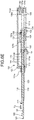
- FIG. 1 is a cross sectional view of a biopsy needle according to an embodiment of the present invention, taken along a plane passing through a central axis in a longitudinal direction of the biopsy needle and a center of a needle tip of an inner needle.
- a biopsy needle 100 includes a tubular outer needle 110 extending in the longitudinal direction, a cylindrical-shaped solid inner needle 120 that is inserted into and movable in the outer needle 110 in the longitudinal direction, and an operating unit 130 that houses proximal ends of the outer needle 110 and the inner needle 120 therein and includes a moving mechanism that causes each of the outer needle 110 and the inner needle 120 to independently slide in the longitudinal direction.
- the outer needle 110 has the tubular shape with a sharp distal end and includes a needle tip 111 (first needle tip) at the distal end in the longitudinal direction.
- the outer needle 110 made of a material having biocompatibility, for example, metal such as stainless, titanium, and aluminum or resin such as fluororesin.
- the inner needle 120 includes a needle tip 121 (second needle tip) formed at a distal end, an inclined surface 122 inclined toward the needle tip 121 at the distal end, and a notch portion 123 including a notch formed on a side surface closer to a proximal end side than the inclined surface 122 to collect body tissue.
- the inner needle 120 made of a material having biocompatibility, similarly to the outer needle 110.
- the needle tip 121 is sharpened by cutting the distal end of the inner needle 120 such that an apex thereof is formed at the side opposite to the inclined surface 122 when viewed in a transverse direction.
- the inclined surface 122 of the distal end of the inner needle 120 is formed using a processing method such as lancet, back-cut, semi-lancet, or flat-sharpening.
- the inner needle 120 may have a prismatic shape instead of the cylindrical shape.
- the operating unit 130 has a configuration in which a trigger button 132, an inner needle charge coil spring 133, an inner needle slider 134, an inner needle knob 135, an inner needle stopper 136, an outer needle fixing hook releasing lever 137, an outer needle charge coil spring 138, an outer needle slider 139, an outer needle knob 140, and an outer needle stopper 141, which function as the moving mechanism, are assembled with an operating unit body 131 that has a hollow columnar shape.
- a lure pipe sleeve portion 131a is provided at a distal end
- a spring assembly convex portion 131b is provided at an internal proximal end
- a trigger button hole 131c is provided in an upper portion of the spring assembly convex portion 131b
- an inner needle knob hole 131d dug in the longitudinal direction is provided in a bottom portion at a proximal end side
- an outer needle knob hole 131e dug in the longitudinal direction is provided in a bottom portion at the distal end side.
- a proximal end of the inner needle charge coil spring 133 to be described later is assembled with the spring assembly convex portion 131b.
- a proximal end of the trigger button 132 to be described later protrudes from the trigger button hole 131c.
- the inner needle knob 135 to be described later is slidable in the longitudinal direction inside the inner needle knob hole 131d.
- the outer needle knob 140 to be described later is slidable in the longitudinal direction inside the outer needle knob hole 131e.
- the trigger button 132 serves as a trigger of an advancing operation of the inner needle 120, and both ends thereof move alternately up and down with a fulcrum 132a, which is connected to the inside of the operating unit body 131, as an axis.
- An inner needle fixing hook 132b to be caught by a concave portion of the inner needle slider 134 to be described later is provided at a distal end of the trigger button 132.
- the inner needle charge coil spring 133 has the proximal end assembled with a proximal end portion of the spring assembly convex portion 131b and a distal end assembled with a side surface at a proximal end side of the inner needle slider 134 to be described later, and biases the inner needle slider 134 toward the distal end direction by being extended after compression (charge).
- the inner needle slider 134 is connected to the proximal end of the inner needle 120 and advances in the distal end direction by being biased toward the distal end direction by the inner needle charge coil spring 133, and accordingly, causes the inner needle 120 to advance in the distal end direction.
- the concave portion to which the inner needle fixing hook 132b is fitted is formed on a top surface of the inner needle slider 134.
- the inner needle knob 135 slides along the inner needle knob hole 131d so as to be able to advance and retract in the longitudinal direction.
- a top surface of the inner needle knob 135 is connected to a bottom surface of the inner needle slider 134.
- a lower portion of the inner needle knob 135 protrudes from the inner needle knob hole 131d.
- the inner needle knob 135 advances inside the inner needle knob hole 131d along with advancing of the inner needle slider 134.
- an operator of the biopsy needle 100 can retract the inner needle slider 134 and the inner needle 120 to the proximal end side by retracting the inner needle knob 135 to the proximal end side along the inner needle knob hole 131d.
- the inner needle fixing hook 132b is fitted into the concave portion of the inner needle slider 134, and the inner needle 120 is fixed at a position located at the most proximal end side.
- the inner needle stopper 136 stops the advancing operation of the inner needle slider 134, and accordingly stops the advancing operation of the inner needle 120.
- Both ends of the outer needle fixing hook releasing lever 137 move up and down with a fulcrum 137a, which is connected to the inner needle stopper 136, as an axis.
- An outer needle fixing hook 137b to be caught by a concave portion of the outer needle slider 139 to be described later is provided at a distal end of the outer needle fixing hook releasing lever 137.
- the outer needle charge coil spring 138 has a proximal end assembled with a side surface at a distal end side of the inner needle stopper 136 and a distal end assembled with a side surface at a proximal end side of the outer needle slider 139 to be described later, and biases the outer needle slider 139 toward the distal end direction by being extended after compression (charge).
- the outer needle slider 139 is connected to the proximal end of the outer needle 110 and advances in the distal end direction by being biased toward the distal end direction by the outer needle charge coil spring 138, and accordingly, causes the outer needle 110 to advance in the distal end direction.
- the concave portion to which the outer needle fixing hook 137b is fitted is formed on a top surface of the outer needle slider 139.
- the outer needle knob 140 slides along the outer needle knob hole 131e so as to be able to advance and retract in the longitudinal direction.
- a top surface of the outer needle knob 140 is connected to a bottom surface of the outer needle slider 139.
- a lower portion of the outer needle knob 140 protrudes from the outer needle knob hole 131e.
- the outer needle knob 140 advances inside the outer needle knob hole 131e along with advancing of the outer needle slider 139.
- the operator of the biopsy needle 100 can retract the outer needle slider 139 and the outer needle 110 to the proximal end side by retracting the outer needle knob 140 to the proximal end side along the outer needle knob hole 131e.
- the outer needle fixing hook 137b is fitted into the concave portion of the outer needle slider 139, and the outer needle 110 is fixed at a position located at the most proximal end side.
- the outer needle stopper 141 is provided at a distal end portion of the operating unit body 131, stops the advancing operation of the outer needle slider 139, and accordingly stops the advancing operation of the outer needle 110.
- a length L 1 of the outer needle knob hole 131e in the longitudinal direction, that is, a stroke (maximum slidable distance) L 1 of the outer needle 110 in the distal end direction is set to be longer than a length L 2 of the inner needle knob hole 131d in the longitudinal direction, that is, the stroke L 2 of the inner needle 120 in the distal end direction.
- the stroke L 2 is set such that the notch portion 123 can be adequately exposed from the needle tip 111 of the outer needle 110 to the extent that the tissue collection is enabled.
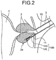
- FIG. 2 is a diagram for explaining a biopsy method implemented by the biopsy needle 100.
- an insertion portion 10 of an ultrasound endoscope is introduced to reach a prostate 2 as a biopsy target via a urethra 3 of a patient using an ultrasound tomogram obtained by the ultrasound endoscope as a guide.
- a distal end of the biopsy needle 100 inserted into a treatment tool channel of the insertion portion 10 is caused to protrude from an aperture portion 11 at a distal end of the insertion portion 10 so that the outer needle 110 and the inner needle 120 puncture the prostate 2.
- the distal end of the inner needle 120 is caused to protrude from the outer needle 110 until the notch portion 123 is exposed, and thereafter, the outer needle 110 is caused to advance in the distal end direction so that body tissue that has entered the inside of the notch is cut by the distal end of the outer needle 110 and the notch portion 123 is covered by the outer needle 110 in a state where the body tissue is caught inside the notch.
- the biopsy needle 100 is pulled out of the body via the treatment tool channel, and thereafter, the body tissue caught inside the notch is collected.
- a bladder 4 is positioned inside the prostate 2.
- the notch portion 123 is extended to the distal end side of the inner needle 120, a first state and a second state to be described later are defined, and the first state and the second state are switched from one to the other in order to reduce a protruding length of the inner needle 120 such that the needle tip of the inner needle 120 does not outwardly penetrate a capsule 2a of the prostate 2 from the inner side thereof, and to enable collection of body tissue in the notch portion 123.
- FIG. 3 is a diagram for explaining the first state and the second state of the biopsy needle 100, and is a cross sectional view of the distal end of the biopsy needle 100 taken along the plane passing through the central axis in the longitudinal direction and the center of the needle tip 121 of the inner needle 120.
- (a) of FIG. 3 is a diagram illustrating the first state.
- the first state is a charge state where both of the inner needle charge coil spring 133 and the outer needle charge coil spring 138 are compressed and charged with energy for extension.
- the first state is a state where the outer needle 110 and the inner needle 120 are charged with energy for protrusion, and is a state obtained when the outer needle 110 and the inner needle 120 puncture a biopsy site.
- FIG. 3 is a diagram for explaining the first state and the second state of the biopsy needle 100, and is a cross sectional view of the distal end of the biopsy needle 100 taken along the plane passing through the central axis in the longitudinal direction and the center of the needle tip 121 of the inner needle 120.
- the needle tip 121 of the inner needle 120 is positioned closer to the distal end side than the needle tip 111 of the outer needle 110. Further, as a distance between the needle tips, that is, as a distance between the needle tip 111 of the outer needle 110 and the needle tip 121 of the inner needle 120 in the longitudinal direction, a first distance D 1 is set. In addition, in the first state, it is ideal that the needle tip 111 of the outer needle 110 is positioned in a region S 1 between a proximal end of the inclined surface 122 of the inner needle 120 and a distal end of the notch portion 123.
- the distance between the needle tip 121 of the inner needle 120 and the distal end of the notch portion 123 is narrowed to about 3 to 4 mm in the case of the biopsy needle 100 of 18 gauge.
- an angle ⁇ of the inclined surface at the distal end of the notch portion 123 with respect to the outer tube surface of the inner needle 120 is set to be larger than an angle ⁇ of the inclined surface of the outer needle 110.
- FIG. 3 is a diagram for explaining the second state of the biopsy needle 100, and is a cross sectional view of the distal end of the outer needle 110 taken along the plane passing through the central axis in the longitudinal direction and the center of the needle tip 121 of the inner needle 120.
- the second state is a state where the inner needle 120 and the outer needle 110 slide to the biopsy site in the distal end direction and the biopsy collection is completed.
- the position of the needle tip 111 of the outer needle 110 in the longitudinal direction is located closer to the distal end side than the proximal end of the inclined surface 122 of the inner needle 120. That is, the outer needle 110 is in a state of entirely covering the notch portion 123 of the inner needle 120.
- the outer needle 110 and the inner needle 120 are positioned such that a distance between the needle tip 111 of the outer needle 110 and the needle tip 121 of the inner needle 120 becomes a second distance D 2 that is shorter than the first distance D 1 . Furthermore, in the second state, it is ideal that the needle tip 111 of the outer needle 110 is positioned in a region S 2 between the needle tip 121 of the inner needle 120 and the proximal end of the inclined surface 122. That is, in the second state, it is ideal that the outer needle 110 and the inner needle 120 are positioned such that the position of the needle tip 111 of the outer needle 110 in the longitudinal direction overlaps with the inclined surface 122 of the inner needle 120.
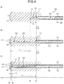
- FIG. 4 is a diagram for explaining protruding operations of the outer needle 110 and the inner needle 120 of the biopsy needle 100.
- FIG. 4 illustrates a case where the inner needle 120 and the outer needle 110 protrude in an x-axis direction.
- FIG. 4 illustrates the first state (charge state) where the needle tip 121 of the inner needle 120 is positioned closer to the distal end side than the needle tip 111 of the outer needle 110, and is a state obtained before a region in the vicinity of the capsule 2a of the prostate 2 as the biopsy site is punctured.
- FIG. 4 illustrates a state where only the inner needle 120 protrudes in the x-axis direction of the distal end side when the inner needle 120 is moved by the moving mechanism in order to collect tissue in the vicinity of the capsule 2a of the prostate 2.
- the inner needle 120 protrudes in the x-axis direction by the above-described stroke L 2 as compared to the first state. Therefore, the needle tip 121 of the inner needle 120 moves in the x-axis direction by the stroke L 2 from a position B 1 in the first state and reaches a position B 2 in the vicinity of the capsule 2a. Consequently, the notch portion 123 is fully exposed, and tissue of the prostate 2 enters the inside of the notch portion 123.
- FIG. 4 illustrates a state where the outer needle 110 also protrudes and the biopsy operation is completed, that is, the second state.
- the outer needle 110 protrudes in the x-axis direction by the stroke L 1 as compared to the first state.
- the stroke L 1 is longer than the stroke L 2 . Therefore, the needle tip 111 of the outer needle 110 located at a position B 3 between the proximal end of the inclined surface 122 of the inner needle 120 and the distal end of the notch portion 123 in the first state passes by the distal end of the notch portion 123 of the inner needle 120, and then reaches a position B 4 beyond the proximal end of the inclined surface 122 of the inner needle 120.
- the protruding needle tip 111 of the outer needle 110 reaches the vicinity of the needle tip 121 of the inner needle 120. Therefore, the distance between the needle tip 111 of the outer needle 110 and the needle tip 121 of the inner needle 120 becomes the second distance D 2 ( ⁇ D 1 ). With the protrusion of the outer needle 110, it is possible to cut the tissue of the prostate 2, which has entered the inside of the notch portion 123, by the needle tip 111 of the outer needle 110, and entirely cover the notch portion 123 by the outer needle 110 in a state where body tissue 2b is caught inside the notch portion 123.
- FIG. 5A and FIG. 5B are cross sectional views of distal ends of conventional biopsy needles 200A and 200B taken along a plane passing through central axes in a longitudinal direction of the biopsy needles 200A and 200B and centers of needle tips 221 of inner needles 220A and 220B.
- a notch portion 223A is extended in a distal end direction to the vicinity of a proximal end of an inclined surface 222 and a length P 1 of the inner needle 220A protruding from a collection target region in tissue is reduced to about 2 to 3 mm as in the biopsy needle 200A illustrated in FIG.
- a large gap C may be generated between a needle tip 211 of an outer needle 210 and the notch portion 223A even when the outer needle 210 protrudes, due to manufacturing variation, temperature change, or the like.
- the biopsy needle 100 is configured such that the notch portion 123 of the inner needle 120 is extended to the vicinity of the proximal end of the inclined surface 122 to reduce the length of the inner needle 120 protruding from a collection target region in tissue, to thereby enable tissue collection without deeply inserting the needle into the tissue.
- the biopsy needle 100 is configured such that the stroke (sliding distance) L 1 of the outer needle 110 in the longitudinal direction is set to be longer than the stroke L 2 of the inner needle 120 in the longitudinal direction in order to enable switching from the first state, which is a charge state where the needle tip 121 of the inner needle 120 is positioned closer to the distal end side than the needle tip 111 of the outer needle 110, to the second state, which is a state where the inner needle 120 and the outer needle 110 slide in the distal end direction and the position of the needle tip 111 of the outer needle 110 in the longitudinal direction is located closer to the distal end side than the proximal end of the inclined surface 122 of the inner needle 120, such that a gap is not generated between the needle tip 111 of the outer needle 110 and the notch portion 123 even when the outer needle 110 protrudes.
- the first state which is a charge state where the needle tip 121 of the inner needle 120 is positioned closer to the distal end side than the needle tip 111 of the outer needle 110
- the second state which is
- a configuration is realized that enables switching from the first state to the second state where the outer needle 110 and the inner needle 120 are positioned such that the distance between the needle tip 111 and the needle tip 121 becomes the second distance D 2 shorter than the first distance D 1 in the first state, and a gap is not generated between the needle tip 111 of the outer needle 110 and the notch portion 123 even when the outer needle 110 protrudes. Therefore, according to the biopsy needle 100, it is possible to reliably cut body tissue by the needle tip 111 of the outer needle 110, and secure the tissue inside the notch portion 123 of the inner needle 120, so that it is possible to collect an adequate amount of tissue.
- the first state is a state before collection of body tissue, and therefore, the needle tip 111 of the outer needle 110 does not necessarily have to be positioned in a place overlapping with the inclined surface 122.
- the needle tip of the outer needle 110 does not necessarily have to reach the distal end of the notch portion 123, but it is sufficient that at least a part of the notch portion 123 is positioned inside the outer needle 110 and it is acceptable that a gap is generated between the needle tip 111 of the outer needle 110 and the notch portion 123.
- the second state it is possible to reliably cut tissue and secure the cut tissue inside the notch portion 123 as long as the outer needle 110 can entirely cover the notch portion 123.
- the position of the needle tip 111 of the outer needle 110 in the longitudinal direction is located closer to the distal end side than the proximal end of the inclined surface 122 of the inner needle 120, and it is not necessary that the position of the needle tip 111 of the outer needle 110 in the longitudinal direction overlaps with the inclined surface 122 of the inner needle 120.
- FIG. 6A to FIG. 6F are diagrams for explaining the biopsy operation of the biopsy needle, and are cross sectional views of the distal end of the biopsy needle 100 taken along a plane passing through the central axis in the longitudinal direction of the biopsy needle 100 and the center of the needle tip of the inner needle 120.
- FIG. 6A is a diagram illustrating the first state of the biopsy needle 100 described above. As illustrated in FIG. 6A , in the first state, the inner needle fixing hook 132b is caught by the concave portion of the inner needle slider 134, the outer needle fixing hook 137b is caught by the concave portion of the outer needle slider 139, and both of the inner needle charge coil spring 133 and the outer needle charge coil spring 138 are compressed and charged with the energy for extension.
- the inner needle fixing hook 132b at the distal end portion moves up with the fulcrum 132a as an axis and is released from the concave portion of the inner needle slider 134, the inner needle charge coil spring 133 that has been compressed extends in the distal end direction as illustrated in FIG. 6C , and the inner needle slider 134 is biased due to the extension of the inner needle charge coil spring 133 and slides in the distal end direction as indicated by an arrow Yb. Accordingly, the inner needle 120 also slides in the distal end direction as indicated by an arrow Yc.
- the inner needle slider 134 and the inner needle knob 135 slide in the distal end direction until coming in contact with the inner needle stopper 136 due to the biasing of the inner needle charge coil spring 133. Accordingly, the inner needle 120 protrudes in the x-axis direction by the stroke L 2 . Furthermore, the inner needle slider 134 presses the outer needle fixing hook releasing lever 137 from the proximal end side as indicated by an arrow Yd due to the biasing of the inner needle charge coil spring 133, so that the outer needle fixing hook 137b at the distal end portion moves up with the fulcrum 137a as an axis as indicated by an arrow Ye and is released from the concave portion of the outer needle slider 139.
- the outer needle charge coil spring 138 that has been compressed extends in the distal end direction as illustrated in FIG. 6E , and the outer needle slider 139 and the outer needle knob 140 move in the distal end direction until coming in contact with the outer needle stopper 141 as indicated by an arrow Yf by being biased by the extension of the outer needle charge coil spring 138. Consequently, the outer needle 110 protrudes in the x-axis direction by the stroke L 1 as indicated by an arrow Yg while cutting the tissue that has entered the notch portion 123 using the needle tip 111, and thus the biopsy needle 100 is switched to the second state as illustrated in FIG. 6F .
- the operator of the biopsy needle 100 pulls out the biopsy needle 100 from the biopsy site in this state. Then, the outer needle 110 is retracted (see FIG. 6D ) by moving the outer needle knob 140 to the proximal end of the outer needle knob hole 131e to expose the notch portion 123, and the body tissue inside the notch portion 123 is collected. Thereafter, the biopsy needle 100 is switched to the first state by moving the inner needle knob 135 to the proximal end of the inner needle knob hole 131d (see FIG. 6A ).
- the biopsy needle 100 includes the moving mechanism configured such that the stroke L 1 of the outer needle 110 in the longitudinal direction is set to be longer than the stroke L 2 of the inner needle 120 in the longitudinal direction, and configured to cause each of the outer needle 110 and the inner needle 120 to independently move in a slidable manner in the longitudinal direction, to thereby enable switching between the first state and the second state.
- the moving mechanism that causes each of the outer needle and the inner needle to independently slide in the longitudinal direction is configured such that a maximum distance (the stroke L 1 ) by which the outer needle 110 is slidable in the distal end direction is set to be longer than a maximum distance (the stroke L 2 ) by which the inner needle 120 is slidable in the distal end direction such that, by movement of the moving mechanism, the outer needle 110 and the inner needle 120 switch between the first state, in which the needle tip 121 is positioned closer to the distal end side than the needle tip 111, and the second state, in which the position of the needle tip 111 in the longitudinal direction is located closer to the distal end side than the proximal end of the inclined surface 122 of the inner needle 121 and a distance between the needle tips is shorter than a distance between the needle tips in the first state.
- the biopsy needle 100 may be inserted from the outside of a body without passing through the treatment tool channel of the ultrasound endoscope, depending on biopsy sites.
- the biopsy needle according to the present invention is useful for reliably collecting tissue and reducing the protruding length of the biopsy needle that protrudes from a collection target region in collecting the tissue.
Landscapes
- Health & Medical Sciences (AREA)
- Life Sciences & Earth Sciences (AREA)
- Surgery (AREA)
- Public Health (AREA)
- Biomedical Technology (AREA)
- Heart & Thoracic Surgery (AREA)
- Medical Informatics (AREA)
- Molecular Biology (AREA)
- Pathology (AREA)
- Animal Behavior & Ethology (AREA)
- General Health & Medical Sciences (AREA)
- Engineering & Computer Science (AREA)
- Veterinary Medicine (AREA)
- Hematology (AREA)
- Immunology (AREA)
- Orthopedic Medicine & Surgery (AREA)
- Rheumatology (AREA)
- Surgical Instruments (AREA)
- Ultra Sonic Daignosis Equipment (AREA)
Abstract
Description
- The present invention relates to a biopsy needle for collecting body tissue.
- Conventionally, a biopsy is performed for pathological definitive diagnosis or the like by introducing a narrow and long biopsy needle to an observed region through a treatment tool channel of an ultrasound endoscope using an ultrasound tomogram obtained by the ultrasound endoscope as a guide, and puncturing lesion tissue to collect body tissue. As a biopsy needle, there is a proposed configuration in which an inner needle with a cutout (notch) for tissue collection formed on a side surface at a distal end side is arranged inside a hollow outer needle, and the inner needle and the outer needle are caused to advance and retract by a moving mechanism (for example, see Patent Literature 1). In the biopsy, puncture is performed with the biopsy needle to reach the tissue of a biopsy site in a state where the outer needle of the biopsy needle substantially covers the notch of the inner needle, and thereafter, the inner needle is caused to protrude from a distal end of the outer needle until the notch is exposed. Accordingly, body tissue enters the inside of the notch, and then the outer needle is caused to advance so that the body tissue that has entered the inside of the notch is cut by the distal end of the outer needle and the notch is covered by the outer needle in a state where the body tissue is caught inside the notch. In this state, the biopsy needle is pulled out from the biopsy site, and thereafter, the notch is exposed by causing the outer needle to retract, and the body tissue inside the notch is collected.
- Patent Literature 1:
JP 2009-531115 A - A biopsy for diagnosis of prostate cancer is currently performed in a transrectal or transperineal manner, but there is a demand for a method of performing a biopsy from the inside of prostate in a transurethral manner in order to reduce invasion to a patient. With this method, it may be possible to further reduce a patient burden without causing a needle tip to contact a nerve traveling an outer side of the prostate as long as a capsule (outer membrane) of the prostate is not penetrated outwardly from the inner side.
- However, in the conventional biopsy needle, the notch that enables collection of a specimen is provided in a portion at a proximal end side separated from the needle tip by about 5 mm. Therefore, if the notch is caused to reach the vicinity of a capsule boundary in order to collect tissue present in the vicinity of the capsule boundary of the prostate, there may be a case where the capsule is penetrated by the needle tip and it is difficult to deny a possibility that the needle tip contacts the nerve. Thus, there is a demand for a configuration that enables collection of tissue in the vicinity of the capsule boundary almost without causing the needle tip of the biopsy needle to move to the outside of the capsule from the capsule of the prostate.
- The present invention has been made in view of the foregoing, and an object of the invention is to provide a biopsy needle capable of reliably collecting tissue and reducing a protruding length of the biopsy needle that protrudes from a collection target region in collecting the tissue.
- To solve the above-described problem and achieve the object, a biopsy needle according to the present invention includes: an outer needle having a tubular shape and including a first needle tip at one end in a longitudinal direction of the outer needle; an inner needle having a columnar shape and configured to be inserted into the outer needle movably in the outer needle in the longitudinal direction of the outer needle, the inner needle including: a second needle tip formed at a distal end of the inner needle; an inclined surface inclined toward the second needle tip at the distal end; and a notch portion comprising a notch formed on a side surface closer to a proximal end of the inner needle than the inclined surface, the notch being configured to collect body tissue; and a moving mechanism configured to cause each of the outer needle and the inner needle to independently slide in the longitudinal direction, and configured such that a maximum distance by which the outer needle is slidable in a distal end direction is set to be longer than a maximum distance by which the inner needle is slidable in the distal end direction such that, by movement of the moving mechanism, the outer needle and the inner needle switch between a first state, in which the second needle tip is positioned closer to a distal end than the first needle tip, and a second state, in which a position of the first needle tip in the longitudinal direction is located closer to the distal end than a proximal end of the inclined surface of the inner needle and a distance between the first needle tip and the second needle tip is shorter than a distance between the first needle tip and the second needle tip in the first state.
- Moreover, in the biopsy needle according to the present invention, the first state is a state where a position of the first needle tip in the longitudinal direction is located closer to a proximal end than the inclined surface of the inner needle.
- Moreover, in the biopsy needle according to the present invention, the first state is a state where at least a part of the notch portion is positioned inside the outer needle.
- Moreover, in the biopsy needle according to the present invention, the inner needle has a cylindrical shape.
- A biopsy needle according to the present invention includes: a moving mechanism configured to cause each of an outer needle and an inner needle to independently slide in a longitudinal direction, and configured such that a maximum distance by which the outer needle is slidable in a distal end direction is set to be longer than a maximum distance by which the inner needle is slidable in the distal end direction such that, by movement of the moving mechanism, the outer needle and the inner needle switch between a first state, in which a second needle tip is positioned closer to a distal end side than a first needle tip, and a second state, in which a position of the first needle tip in the longitudinal direction is located closer to the distal end side than a proximal end of an inclined surface of the inner needle and a distance between the first needle tip and the second needle tip is shorter than a distance between the first needle tip and the second needle tip in the first state. Therefore, it is possible to reliably collect tissue and reduce a protruding length of the biopsy needle that protrudes from a collection target region in collecting the tissue.
-
-
FIG. 1 is a cross sectional view of a biopsy needle according to an embodiment of the present invention, taken along a plane passing through a central axis in a longitudinal direction of the biopsy needle and a center of a needle tip of an inner needle. -
FIG. 2 is a diagram for explaining a biopsy method implemented by the biopsy needle illustrated inFIG. 1 . -
FIG. 3 is a diagram for explaining a first state and a second state of the biopsy needle illustrated inFIG. 1 . -
FIG. 4 is a diagram for explaining protruding operations of an outer needle and the inner needle of the biopsy needle illustrated inFIG. 1 . -
FIG. 5A is a cross sectional view of a distal end of a conventional biopsy needle taken along a plane passing through a central axis in a longitudinal direction of the biopsy needle and a center of a needle tip of an inner needle. -
FIG. 5B is a cross sectional view of a distal end of a conventional biopsy needle taken along a plane passing through a central axis in a longitudinal direction of the biopsy needle and a center of a needle tip of an inner needle. -
FIG. 6A is a diagram for explaining a biopsy operation of the biopsy needle illustrated inFIG. 1 . -
FIG. 6B is a diagram for explaining a biopsy operation of the biopsy needle. -
FIG. 6C is a diagram for explaining a biopsy operation of the biopsy needle. -
FIG. 6D is a diagram for explaining a biopsy operation of the biopsy needle. -
FIG. 6E is a diagram for explaining a biopsy operation of the biopsy needle. -
FIG. 6F is a diagram for explaining a biopsy operation of the biopsy needle. - Hereinafter, modes for carrying out the present invention will be described in detail with reference to the drawings. The present invention is not limited to the embodiments below. The drawings referred to in the descriptions below schematically illustrate shapes, sizes, and positional relationships merely to make contents of the present invention understandable. That is, the present invention is not limited to only the shapes, the sizes, and the positional relationships illustrated in the individual drawings. In the following descriptions, an exemplary biopsy needle configured to puncture the interior of body tissue of an animal including a human and to collect the body tissue will be described. However, the present invention is not limited to the embodiments. The same reference signs are used to designate the same elements throughout the drawings.
-
FIG. 1 is a cross sectional view of a biopsy needle according to an embodiment of the present invention, taken along a plane passing through a central axis in a longitudinal direction of the biopsy needle and a center of a needle tip of an inner needle. - As illustrated in
FIG. 1 , abiopsy needle 100 according to a first embodiment includes a tubularouter needle 110 extending in the longitudinal direction, a cylindrical-shaped solidinner needle 120 that is inserted into and movable in theouter needle 110 in the longitudinal direction, and anoperating unit 130 that houses proximal ends of theouter needle 110 and theinner needle 120 therein and includes a moving mechanism that causes each of theouter needle 110 and theinner needle 120 to independently slide in the longitudinal direction. - The
outer needle 110 has the tubular shape with a sharp distal end and includes a needle tip 111 (first needle tip) at the distal end in the longitudinal direction. Theouter needle 110 made of a material having biocompatibility, for example, metal such as stainless, titanium, and aluminum or resin such as fluororesin. - The
inner needle 120 includes a needle tip 121 (second needle tip) formed at a distal end, aninclined surface 122 inclined toward theneedle tip 121 at the distal end, and anotch portion 123 including a notch formed on a side surface closer to a proximal end side than theinclined surface 122 to collect body tissue. Theinner needle 120 made of a material having biocompatibility, similarly to theouter needle 110. Theneedle tip 121 is sharpened by cutting the distal end of theinner needle 120 such that an apex thereof is formed at the side opposite to theinclined surface 122 when viewed in a transverse direction. Theinclined surface 122 of the distal end of theinner needle 120 is formed using a processing method such as lancet, back-cut, semi-lancet, or flat-sharpening. Theinner needle 120 may have a prismatic shape instead of the cylindrical shape. - The
operating unit 130 has a configuration in which atrigger button 132, an inner needlecharge coil spring 133, aninner needle slider 134, aninner needle knob 135, an inner needle stopper 136, an outer needle fixinghook releasing lever 137, an outer needlecharge coil spring 138, anouter needle slider 139, anouter needle knob 140, and anouter needle stopper 141, which function as the moving mechanism, are assembled with anoperating unit body 131 that has a hollow columnar shape. - In the
operating unit body 131, a lurepipe sleeve portion 131a is provided at a distal end, a spring assemblyconvex portion 131b is provided at an internal proximal end, atrigger button hole 131c is provided in an upper portion of the spring assemblyconvex portion 131b, an innerneedle knob hole 131d dug in the longitudinal direction is provided in a bottom portion at a proximal end side, and an outerneedle knob hole 131e dug in the longitudinal direction is provided in a bottom portion at the distal end side. The distal ends of theouter needle 110 and theinner needle 120 protrude in the distal end direction from the lurepipe sleeve portion 131a. A proximal end of the inner needlecharge coil spring 133 to be described later is assembled with the spring assemblyconvex portion 131b. A proximal end of thetrigger button 132 to be described later protrudes from thetrigger button hole 131c. Theinner needle knob 135 to be described later is slidable in the longitudinal direction inside the innerneedle knob hole 131d. Theouter needle knob 140 to be described later is slidable in the longitudinal direction inside the outerneedle knob hole 131e. - The
trigger button 132 serves as a trigger of an advancing operation of theinner needle 120, and both ends thereof move alternately up and down with afulcrum 132a, which is connected to the inside of theoperating unit body 131, as an axis. An innerneedle fixing hook 132b to be caught by a concave portion of theinner needle slider 134 to be described later is provided at a distal end of thetrigger button 132. - The inner needle
charge coil spring 133 has the proximal end assembled with a proximal end portion of the spring assemblyconvex portion 131b and a distal end assembled with a side surface at a proximal end side of theinner needle slider 134 to be described later, and biases theinner needle slider 134 toward the distal end direction by being extended after compression (charge). - The
inner needle slider 134 is connected to the proximal end of theinner needle 120 and advances in the distal end direction by being biased toward the distal end direction by the inner needlecharge coil spring 133, and accordingly, causes theinner needle 120 to advance in the distal end direction. The concave portion to which the innerneedle fixing hook 132b is fitted is formed on a top surface of theinner needle slider 134. - The
inner needle knob 135 slides along the innerneedle knob hole 131d so as to be able to advance and retract in the longitudinal direction. A top surface of theinner needle knob 135 is connected to a bottom surface of theinner needle slider 134. A lower portion of theinner needle knob 135 protrudes from the innerneedle knob hole 131d. Theinner needle knob 135 advances inside the innerneedle knob hole 131d along with advancing of theinner needle slider 134. In addition, an operator of thebiopsy needle 100 can retract theinner needle slider 134 and theinner needle 120 to the proximal end side by retracting theinner needle knob 135 to the proximal end side along the innerneedle knob hole 131d. When theinner needle knob 135 retracts to a proximal end of the innerneedle knob hole 131d, the innerneedle fixing hook 132b is fitted into the concave portion of theinner needle slider 134, and theinner needle 120 is fixed at a position located at the most proximal end side. - The
inner needle stopper 136 stops the advancing operation of theinner needle slider 134, and accordingly stops the advancing operation of theinner needle 120. - Both ends of the outer needle fixing
hook releasing lever 137 move up and down with afulcrum 137a, which is connected to theinner needle stopper 136, as an axis. An outerneedle fixing hook 137b to be caught by a concave portion of theouter needle slider 139 to be described later is provided at a distal end of the outer needle fixinghook releasing lever 137. - The outer needle
charge coil spring 138 has a proximal end assembled with a side surface at a distal end side of theinner needle stopper 136 and a distal end assembled with a side surface at a proximal end side of theouter needle slider 139 to be described later, and biases theouter needle slider 139 toward the distal end direction by being extended after compression (charge). - The
outer needle slider 139 is connected to the proximal end of theouter needle 110 and advances in the distal end direction by being biased toward the distal end direction by the outer needlecharge coil spring 138, and accordingly, causes theouter needle 110 to advance in the distal end direction. The concave portion to which the outerneedle fixing hook 137b is fitted is formed on a top surface of theouter needle slider 139. - The
outer needle knob 140 slides along the outerneedle knob hole 131e so as to be able to advance and retract in the longitudinal direction. A top surface of theouter needle knob 140 is connected to a bottom surface of theouter needle slider 139. A lower portion of theouter needle knob 140 protrudes from the outerneedle knob hole 131e. Theouter needle knob 140 advances inside the outerneedle knob hole 131e along with advancing of theouter needle slider 139. In addition, the operator of thebiopsy needle 100 can retract theouter needle slider 139 and theouter needle 110 to the proximal end side by retracting theouter needle knob 140 to the proximal end side along the outerneedle knob hole 131e. When theouter needle knob 140 retracts to a proximal end of the outerneedle knob hole 131e, the outerneedle fixing hook 137b is fitted into the concave portion of theouter needle slider 139, and theouter needle 110 is fixed at a position located at the most proximal end side. - The
outer needle stopper 141 is provided at a distal end portion of theoperating unit body 131, stops the advancing operation of theouter needle slider 139, and accordingly stops the advancing operation of theouter needle 110. - A length L1 of the outer
needle knob hole 131e in the longitudinal direction, that is, a stroke (maximum slidable distance) L1 of theouter needle 110 in the distal end direction is set to be longer than a length L2 of the innerneedle knob hole 131d in the longitudinal direction, that is, the stroke L2 of theinner needle 120 in the distal end direction. The stroke L2 is set such that thenotch portion 123 can be adequately exposed from theneedle tip 111 of theouter needle 110 to the extent that the tissue collection is enabled. -
FIG. 2 is a diagram for explaining a biopsy method implemented by thebiopsy needle 100. For example, as illustrated inFIG. 2 , aninsertion portion 10 of an ultrasound endoscope is introduced to reach aprostate 2 as a biopsy target via aurethra 3 of a patient using an ultrasound tomogram obtained by the ultrasound endoscope as a guide. A distal end of thebiopsy needle 100 inserted into a treatment tool channel of theinsertion portion 10 is caused to protrude from anaperture portion 11 at a distal end of theinsertion portion 10 so that theouter needle 110 and theinner needle 120 puncture theprostate 2. The distal end of theinner needle 120 is caused to protrude from theouter needle 110 until thenotch portion 123 is exposed, and thereafter, theouter needle 110 is caused to advance in the distal end direction so that body tissue that has entered the inside of the notch is cut by the distal end of theouter needle 110 and thenotch portion 123 is covered by theouter needle 110 in a state where the body tissue is caught inside the notch. In this state, thebiopsy needle 100 is pulled out of the body via the treatment tool channel, and thereafter, the body tissue caught inside the notch is collected. Abladder 4 is positioned inside theprostate 2. - In the
biopsy needle 100 according to the embodiment, thenotch portion 123 is extended to the distal end side of theinner needle 120, a first state and a second state to be described later are defined, and the first state and the second state are switched from one to the other in order to reduce a protruding length of theinner needle 120 such that the needle tip of theinner needle 120 does not outwardly penetrate acapsule 2a of theprostate 2 from the inner side thereof, and to enable collection of body tissue in thenotch portion 123. -
FIG. 3 is a diagram for explaining the first state and the second state of thebiopsy needle 100, and is a cross sectional view of the distal end of thebiopsy needle 100 taken along the plane passing through the central axis in the longitudinal direction and the center of theneedle tip 121 of theinner needle 120. (a) ofFIG. 3 is a diagram illustrating the first state. The first state is a charge state where both of the inner needlecharge coil spring 133 and the outer needlecharge coil spring 138 are compressed and charged with energy for extension. In other words, the first state is a state where theouter needle 110 and theinner needle 120 are charged with energy for protrusion, and is a state obtained when theouter needle 110 and theinner needle 120 puncture a biopsy site. As illustrated in (a) ofFIG. 3 , in the first state, theneedle tip 121 of theinner needle 120 is positioned closer to the distal end side than theneedle tip 111 of theouter needle 110. Further, as a distance between the needle tips, that is, as a distance between theneedle tip 111 of theouter needle 110 and theneedle tip 121 of theinner needle 120 in the longitudinal direction, a first distance D1 is set. In addition, in the first state, it is ideal that theneedle tip 111 of theouter needle 110 is positioned in a region S1 between a proximal end of theinclined surface 122 of theinner needle 120 and a distal end of thenotch portion 123. For example, the distance between theneedle tip 121 of theinner needle 120 and the distal end of thenotch portion 123 is narrowed to about 3 to 4 mm in the case of thebiopsy needle 100 of 18 gauge. Furthermore, to increase the amount of tissue collected in thenotch portion 123, an angle β of the inclined surface at the distal end of thenotch portion 123 with respect to the outer tube surface of theinner needle 120 is set to be larger than an angle α of the inclined surface of theouter needle 110. - (b) of
FIG. 3 is a diagram for explaining the second state of thebiopsy needle 100, and is a cross sectional view of the distal end of theouter needle 110 taken along the plane passing through the central axis in the longitudinal direction and the center of theneedle tip 121 of theinner needle 120. The second state is a state where theinner needle 120 and theouter needle 110 slide to the biopsy site in the distal end direction and the biopsy collection is completed. In the second state, the position of theneedle tip 111 of theouter needle 110 in the longitudinal direction is located closer to the distal end side than the proximal end of theinclined surface 122 of theinner needle 120. That is, theouter needle 110 is in a state of entirely covering thenotch portion 123 of theinner needle 120. In addition, in the second state, theouter needle 110 and theinner needle 120 are positioned such that a distance between theneedle tip 111 of theouter needle 110 and theneedle tip 121 of theinner needle 120 becomes a second distance D2 that is shorter than the first distance D1. Furthermore, in the second state, it is ideal that theneedle tip 111 of theouter needle 110 is positioned in a region S2 between theneedle tip 121 of theinner needle 120 and the proximal end of theinclined surface 122. That is, in the second state, it is ideal that theouter needle 110 and theinner needle 120 are positioned such that the position of theneedle tip 111 of theouter needle 110 in the longitudinal direction overlaps with theinclined surface 122 of theinner needle 120. - Next,
FIG. 4 is a diagram for explaining protruding operations of theouter needle 110 and theinner needle 120 of thebiopsy needle 100.FIG. 4 illustrates a case where theinner needle 120 and theouter needle 110 protrude in an x-axis direction. - (a) of
FIG. 4 illustrates the first state (charge state) where theneedle tip 121 of theinner needle 120 is positioned closer to the distal end side than theneedle tip 111 of theouter needle 110, and is a state obtained before a region in the vicinity of thecapsule 2a of theprostate 2 as the biopsy site is punctured. - (b) of
FIG. 4 illustrates a state where only theinner needle 120 protrudes in the x-axis direction of the distal end side when theinner needle 120 is moved by the moving mechanism in order to collect tissue in the vicinity of thecapsule 2a of theprostate 2. In this case, theinner needle 120 protrudes in the x-axis direction by the above-described stroke L2 as compared to the first state. Therefore, theneedle tip 121 of theinner needle 120 moves in the x-axis direction by the stroke L2 from a position B1 in the first state and reaches a position B2 in the vicinity of thecapsule 2a. Consequently, thenotch portion 123 is fully exposed, and tissue of theprostate 2 enters the inside of thenotch portion 123. - (c) of
FIG. 4 illustrates a state where theouter needle 110 also protrudes and the biopsy operation is completed, that is, the second state. Theouter needle 110 protrudes in the x-axis direction by the stroke L1 as compared to the first state. The stroke L1 is longer than the stroke L2. Therefore, theneedle tip 111 of theouter needle 110 located at a position B3 between the proximal end of theinclined surface 122 of theinner needle 120 and the distal end of thenotch portion 123 in the first state passes by the distal end of thenotch portion 123 of theinner needle 120, and then reaches a position B4 beyond the proximal end of theinclined surface 122 of theinner needle 120. In other words, after theinner needle 120 and theouter needle 110 protrude in sequence, the protrudingneedle tip 111 of theouter needle 110 reaches the vicinity of theneedle tip 121 of theinner needle 120. Therefore, the distance between theneedle tip 111 of theouter needle 110 and theneedle tip 121 of theinner needle 120 becomes the second distance D2 (< D1). With the protrusion of theouter needle 110, it is possible to cut the tissue of theprostate 2, which has entered the inside of thenotch portion 123, by theneedle tip 111 of theouter needle 110, and entirely cover thenotch portion 123 by theouter needle 110 in a state wherebody tissue 2b is caught inside thenotch portion 123. - Next, conventional biopsy needles will be described.
FIG. 5A and FIG. 5B are cross sectional views of distal ends of conventional biopsy needles 200A and 200B taken along a plane passing through central axes in a longitudinal direction of the biopsy needles 200A and 200B and centers ofneedle tips 221 ofinner needles notch portion 223A is extended in a distal end direction to the vicinity of a proximal end of aninclined surface 222 and a length P1 of theinner needle 220A protruding from a collection target region in tissue is reduced to about 2 to 3 mm as in thebiopsy needle 200A illustrated inFIG. 5A in order to perform tissue collection without deeply inserting the needle into the tissue, a large gap C may be generated between aneedle tip 211 of anouter needle 210 and thenotch portion 223A even when theouter needle 210 protrudes, due to manufacturing variation, temperature change, or the like. In this case, it is difficult to cut body tissue by theneedle tip 211 of theouter needle 210, and it is difficult to collect an adequate amount of tissue because tissue escapes from the gap C when thebiopsy needle 200A is pulled out. Therefore, conventionally, it has been necessary to increase a length P2 from theneedle tip 221 of theinner needle 220B to anotch portion 223B to about 5 to 6 mm to set a certain margin so that even a distal end of thenotch portion 223B can be substantially covered after theouter needle 210 protrudes as in thebiopsy needle 200B illustrated inFIG. 5B . Thus, in thebiopsy needle 200B, theneedle tip 221 of the inner needle 220 needs to deeply puncture to a depth deeper than a region where tissue to be collected is present, as compared to thebiopsy needle 200A. - In contrast, the
biopsy needle 100 according to the embodiment is configured such that thenotch portion 123 of theinner needle 120 is extended to the vicinity of the proximal end of theinclined surface 122 to reduce the length of theinner needle 120 protruding from a collection target region in tissue, to thereby enable tissue collection without deeply inserting the needle into the tissue. In addition, thebiopsy needle 100 is configured such that the stroke (sliding distance) L1 of theouter needle 110 in the longitudinal direction is set to be longer than the stroke L2 of theinner needle 120 in the longitudinal direction in order to enable switching from the first state, which is a charge state where theneedle tip 121 of theinner needle 120 is positioned closer to the distal end side than theneedle tip 111 of theouter needle 110, to the second state, which is a state where theinner needle 120 and theouter needle 110 slide in the distal end direction and the position of theneedle tip 111 of theouter needle 110 in the longitudinal direction is located closer to the distal end side than the proximal end of theinclined surface 122 of theinner needle 120, such that a gap is not generated between theneedle tip 111 of theouter needle 110 and thenotch portion 123 even when theouter needle 110 protrudes. That is, a configuration is realized that enables switching from the first state to the second state where theouter needle 110 and theinner needle 120 are positioned such that the distance between theneedle tip 111 and theneedle tip 121 becomes the second distance D2 shorter than the first distance D1 in the first state, and a gap is not generated between theneedle tip 111 of theouter needle 110 and thenotch portion 123 even when theouter needle 110 protrudes. Therefore, according to thebiopsy needle 100, it is possible to reliably cut body tissue by theneedle tip 111 of theouter needle 110, and secure the tissue inside thenotch portion 123 of theinner needle 120, so that it is possible to collect an adequate amount of tissue. - Meanwhile, the first state is a state before collection of body tissue, and therefore, the
needle tip 111 of theouter needle 110 does not necessarily have to be positioned in a place overlapping with theinclined surface 122. In other words, in the first state, the needle tip of theouter needle 110 does not necessarily have to reach the distal end of thenotch portion 123, but it is sufficient that at least a part of thenotch portion 123 is positioned inside theouter needle 110 and it is acceptable that a gap is generated between theneedle tip 111 of theouter needle 110 and thenotch portion 123. Furthermore, in the second state, it is possible to reliably cut tissue and secure the cut tissue inside thenotch portion 123 as long as theouter needle 110 can entirely cover thenotch portion 123. Therefore, it is sufficient that the position of theneedle tip 111 of theouter needle 110 in the longitudinal direction is located closer to the distal end side than the proximal end of theinclined surface 122 of theinner needle 120, and it is not necessary that the position of theneedle tip 111 of theouter needle 110 in the longitudinal direction overlaps with theinclined surface 122 of theinner needle 120. - Next, a biopsy operation of the biopsy needle will be described in detail.
FIG. 6A to FIG. 6F are diagrams for explaining the biopsy operation of the biopsy needle, and are cross sectional views of the distal end of thebiopsy needle 100 taken along a plane passing through the central axis in the longitudinal direction of thebiopsy needle 100 and the center of the needle tip of theinner needle 120. -
FIG. 6A is a diagram illustrating the first state of thebiopsy needle 100 described above. As illustrated inFIG. 6A , in the first state, the innerneedle fixing hook 132b is caught by the concave portion of theinner needle slider 134, the outerneedle fixing hook 137b is caught by the concave portion of theouter needle slider 139, and both of the inner needlecharge coil spring 133 and the outer needlecharge coil spring 138 are compressed and charged with the energy for extension. - When the
trigger button 132 is pressed as indicated by an arrow Ya inFIG. 6B , the innerneedle fixing hook 132b at the distal end portion moves up with thefulcrum 132a as an axis and is released from the concave portion of theinner needle slider 134, the inner needlecharge coil spring 133 that has been compressed extends in the distal end direction as illustrated inFIG. 6C , and theinner needle slider 134 is biased due to the extension of the inner needlecharge coil spring 133 and slides in the distal end direction as indicated by an arrow Yb. Accordingly, theinner needle 120 also slides in the distal end direction as indicated by an arrow Yc. - Further, as illustrated in
FIG. 6D , theinner needle slider 134 and theinner needle knob 135 slide in the distal end direction until coming in contact with theinner needle stopper 136 due to the biasing of the inner needlecharge coil spring 133. Accordingly, theinner needle 120 protrudes in the x-axis direction by the stroke L2. Furthermore, theinner needle slider 134 presses the outer needle fixinghook releasing lever 137 from the proximal end side as indicated by an arrow Yd due to the biasing of the inner needlecharge coil spring 133, so that the outerneedle fixing hook 137b at the distal end portion moves up with thefulcrum 137a as an axis as indicated by an arrow Ye and is released from the concave portion of theouter needle slider 139. Accordingly, the outer needlecharge coil spring 138 that has been compressed extends in the distal end direction as illustrated inFIG. 6E , and theouter needle slider 139 and theouter needle knob 140 move in the distal end direction until coming in contact with theouter needle stopper 141 as indicated by an arrow Yf by being biased by the extension of the outer needlecharge coil spring 138. Consequently, theouter needle 110 protrudes in the x-axis direction by the stroke L1 as indicated by an arrow Yg while cutting the tissue that has entered thenotch portion 123 using theneedle tip 111, and thus thebiopsy needle 100 is switched to the second state as illustrated inFIG. 6F . - The operator of the
biopsy needle 100 pulls out thebiopsy needle 100 from the biopsy site in this state. Then, theouter needle 110 is retracted (seeFIG. 6D ) by moving theouter needle knob 140 to the proximal end of the outerneedle knob hole 131e to expose thenotch portion 123, and the body tissue inside thenotch portion 123 is collected. Thereafter, thebiopsy needle 100 is switched to the first state by moving theinner needle knob 135 to the proximal end of the innerneedle knob hole 131d (seeFIG. 6A ). - In this manner, the
biopsy needle 100 includes the moving mechanism configured such that the stroke L1 of theouter needle 110 in the longitudinal direction is set to be longer than the stroke L2 of theinner needle 120 in the longitudinal direction, and configured to cause each of theouter needle 110 and theinner needle 120 to independently move in a slidable manner in the longitudinal direction, to thereby enable switching between the first state and the second state. The moving mechanism that causes each of the outer needle and the inner needle to independently slide in the longitudinal direction is configured such that a maximum distance (the stroke L1) by which theouter needle 110 is slidable in the distal end direction is set to be longer than a maximum distance (the stroke L2) by which theinner needle 120 is slidable in the distal end direction such that, by movement of the moving mechanism, theouter needle 110 and theinner needle 120 switch between the first state, in which theneedle tip 121 is positioned closer to the distal end side than theneedle tip 111, and the second state, in which the position of theneedle tip 111 in the longitudinal direction is located closer to the distal end side than the proximal end of theinclined surface 122 of theinner needle 121 and a distance between the needle tips is shorter than a distance between the needle tips in the first state. - While an example has been described in the embodiment in which the tissue of the
prostate 2 is collected using thebiopsy needle 100, it is of course possible to use the disclosed technology to collect tissue in other regions. In addition, while an example has been described in the embodiment in which the distal end of thebiopsy needle 100 is caused to reach the biopsy site through the treatment tool channel of theinsertion portion 10 of the ultrasound endoscope, thebiopsy needle 100 may be inserted from the outside of a body without passing through the treatment tool channel of the ultrasound endoscope, depending on biopsy sites. - As described above, the biopsy needle according to the present invention is useful for reliably collecting tissue and reducing the protruding length of the biopsy needle that protrudes from a collection target region in collecting the tissue.
-
- 2
- PROSTATE
- 2a
- CAPSULE
- 3
- URETHRA
- 4
- BLADDER
- 10
- INSERTION PORTION
- 11
- APERTURE PORTION
- 100, 200A, 200B
- BIOPSY NEEDLE
- 110, 210
- OUTER NEEDLE
- 111, 121, 211, 221
- NEEDLE TIP
- 120, 220A, 220B
- INNER NEEDLE
- 122, 222
- INCLINED SURFACE
- 123, 223A, 223B
- NOTCH PORTION
- 130
- OPERATING UNIT
- 131
- OPERATING UNIT BODY
- 131a
- LURE PIPE SLEEVE PORTION
- 131b
- SPRING ASSEMBLY CONVEX PORTION
- 131c
- TRIGGER BUTTON HOLE
- 131d
- INNER NEEDLE KNOB HOLE
- 131e
- OUTER NEEDLE KNOB HOLE
- 132
- TRIGGER BUTTON
- 132a, 137a
- FULCRUM
- 132b
- INNER NEEDLE FIXING HOOK
- 133
- INNER NEEDLE CHARGE COIL SPRING
- 134
- INNER NEEDLE SLIDER
- 135
- INNER NEEDLE KNOB
- 136
- INNER NEEDLE STOPPER
- 137
- OUTER NEEDLE FIXING HOOK RELEASING LEVER
- 137b
- OUTER NEEDLE FIXING HOOK
- 138
- OUTER NEEDLE CHARGE COIL SPRING
- 139
- OUTER NEEDLE SLIDER
- 140
- OUTER NEEDLE KNOB
- 141
- OUTER NEEDLE STOPPER
Claims (4)
- A biopsy needle comprising:an outer needle having a tubular shape and including a first needle tip at one end in a longitudinal direction of the outer needle;an inner needle having a columnar shape and configured to be inserted into the outer needle movably in the outer needle in the longitudinal direction of the outer needle, the inner needle including:a second needle tip formed at a distal end of the inner needle;an inclined surface inclined toward the second needle tip at the distal end; anda notch portion comprising a notch formed on a side surface closer to a proximal end of the inner needle than the inclined surface, the notch being configured to collect body tissue; anda moving mechanismconfigured to cause each of the outer needle and the inner needle to independently slide in the longitudinal direction, andconfigured such that a maximum distance by which the outer needle is slidable in a distal end direction is set to be longer than a maximum distance by which the inner needle is slidable in the distal end direction such that, by movement of the moving mechanism, the outer needle and the inner needle switch between a first state, in which the second needle tip is positioned closer to a distal end than the first needle tip, and a second state, in which a position of the first needle tip in the longitudinal direction is located closer to the distal end than a proximal end of the inclined surface of the inner needle and a distance between the first needle tip and the second needle tip is shorter than a distance between the first needle tip and the second needle tip in the first state.
- The biopsy needle according to claim 1, wherein the first state is a state where a position of the first needle tip in the longitudinal direction is located closer to a proximal end than the inclined surface of the inner needle.
- The biopsy needle according to claim 1, wherein the first state is a state where at least a part of the notch portion is positioned inside the outer needle.
- The biopsy needle according to claim 1, wherein the inner needle has a cylindrical shape.
Applications Claiming Priority (2)
| Application Number | Priority Date | Filing Date | Title |
|---|---|---|---|
| JP2015117828 | 2015-06-10 | ||
| PCT/JP2016/065691 WO2016199597A1 (en) | 2015-06-10 | 2016-05-27 | Biopsy needle |
Publications (2)
| Publication Number | Publication Date |
|---|---|
| EP3308716A1 true EP3308716A1 (en) | 2018-04-18 |
| EP3308716A4 EP3308716A4 (en) | 2019-01-30 |
Family
ID=57503724
Family Applications (1)
| Application Number | Title | Priority Date | Filing Date |
|---|---|---|---|
| EP16807304.7A Withdrawn EP3308716A4 (en) | 2015-06-10 | 2016-05-27 | Biopsy needle |
Country Status (5)
| Country | Link |
|---|---|
| US (1) | US20180098758A1 (en) |
| EP (1) | EP3308716A4 (en) |
| JP (1) | JP6239197B2 (en) |
| CN (1) | CN107683114A (en) |
| WO (1) | WO2016199597A1 (en) |
Cited By (1)
| Publication number | Priority date | Publication date | Assignee | Title |
|---|---|---|---|---|
| US12137887B2 (en) | 2017-11-30 | 2024-11-12 | C. R. Bard, Inc. | Sample container and coaxial introducer cannula for a biopsy apparatus |
Families Citing this family (10)
| Publication number | Priority date | Publication date | Assignee | Title |
|---|---|---|---|---|
| JP2512618B2 (en) | 1990-08-31 | 1996-07-03 | 株式会社東海理化電機製作所 | Sliding contact grease |
| TWI734958B (en) | 2018-03-19 | 2021-08-01 | 日商泰爾茂股份有限公司 | Puncture needle and catheter assembly |
| EP3646797B1 (en) * | 2018-11-01 | 2021-05-19 | National University of Ireland, Galway | A biopsy device |
| CN110537941A (en) * | 2019-09-17 | 2019-12-06 | 哈尔滨理工大学 | A rotary oblique biopsy needle |
| US12279793B2 (en) * | 2019-10-16 | 2025-04-22 | Fresenius Kabi Deutschland Gmbh | Cannula device |
| WO2021090986A1 (en) * | 2019-11-08 | 2021-05-14 | 주식회사 플라워메디칼 | Biopsy needle set |
| NL2027205B1 (en) * | 2020-12-22 | 2022-07-20 | Univ Delft Tech | An endoluminal biopsy tool |
| EP4274498A4 (en) * | 2021-01-08 | 2024-11-27 | Sonex Health, Inc. | Surgical cutting device for ultrasonic guided soft tissue surgery |
| CN113349838A (en) * | 2021-06-02 | 2021-09-07 | 陕西省肿瘤医院 | Puncture sampler for oncology department |
| CN115054289A (en) * | 2022-07-01 | 2022-09-16 | 四川普瑞顺祥医疗器械有限公司 | Pneumatic rotary cutter structure |
Family Cites Families (15)
| Publication number | Priority date | Publication date | Assignee | Title |
|---|---|---|---|---|
| US5090419A (en) * | 1990-08-23 | 1992-02-25 | Aubrey Palestrant | Apparatus for acquiring soft tissue biopsy specimens |
| US5284156A (en) * | 1991-08-30 | 1994-02-08 | M3 Systems, Inc. | Automatic tissue sampling apparatus |
| JPH07289555A (en) * | 1994-04-20 | 1995-11-07 | Sainetsukusu Internatl Kk | Biopsy needle device |
| US5842999A (en) * | 1996-07-31 | 1998-12-01 | C.R. Bard, Inc. | Automated tissue sampling device |
| WO1998033435A1 (en) * | 1997-01-30 | 1998-08-06 | Boston Scientific Corporation | Pneumatically actuated tissue sampling device |
| US7131951B2 (en) * | 2002-03-20 | 2006-11-07 | Board Of Regents, The University Of Texas System | Biopsy needle |
| FR2845266B1 (en) * | 2002-10-03 | 2004-12-17 | Porges Sa | DEVICE FOR TAKING A BODY SAMPLE |
| US9332971B2 (en) * | 2005-04-28 | 2016-05-10 | Boston Scientific Scimed, Inc. | Biopsy systems |
| US7662109B2 (en) * | 2006-02-01 | 2010-02-16 | Ethicon Endo-Surgery, Inc. | Biopsy device with replaceable probe incorporating static vacuum source dual valve sample stacking retrieval and saline flush |
| CN101534740B (en) * | 2006-09-12 | 2012-06-20 | 维达保健公司 | Medical procedure tray with intraosseous devices |
| US20090131819A1 (en) * | 2007-11-20 | 2009-05-21 | Ritchie Paul G | User Interface On Biopsy Device |
| US8622927B2 (en) * | 2008-12-18 | 2014-01-07 | Devicor Medical Products, Inc. | Mechanical tissue sample holder indexing device |
| US8206316B2 (en) * | 2009-06-12 | 2012-06-26 | Devicor Medical Products, Inc. | Tetherless biopsy device with reusable portion |
| US20120022397A1 (en) * | 2010-07-22 | 2012-01-26 | Jarial Inderjeet S | Needle Set for a Biopsy Device and Related Method |
| WO2014091502A1 (en) * | 2012-12-14 | 2014-06-19 | Secretary, Department Of Biotechnology | Devices and methods for biopsy |
-
2016
- 2016-05-27 JP JP2017521255A patent/JP6239197B2/en active Active
- 2016-05-27 CN CN201680033265.9A patent/CN107683114A/en active Pending
- 2016-05-27 EP EP16807304.7A patent/EP3308716A4/en not_active Withdrawn
- 2016-05-27 WO PCT/JP2016/065691 patent/WO2016199597A1/en not_active Ceased
-
2017
- 2017-12-08 US US15/836,013 patent/US20180098758A1/en not_active Abandoned
Cited By (1)
| Publication number | Priority date | Publication date | Assignee | Title |
|---|---|---|---|---|
| US12137887B2 (en) | 2017-11-30 | 2024-11-12 | C. R. Bard, Inc. | Sample container and coaxial introducer cannula for a biopsy apparatus |
Also Published As
| Publication number | Publication date |
|---|---|
| EP3308716A4 (en) | 2019-01-30 |
| CN107683114A (en) | 2018-02-09 |
| US20180098758A1 (en) | 2018-04-12 |
| JPWO2016199597A1 (en) | 2017-08-31 |
| WO2016199597A1 (en) | 2016-12-15 |
| JP6239197B2 (en) | 2017-11-29 |
Similar Documents
| Publication | Publication Date | Title |
|---|---|---|
| EP3308716A1 (en) | Biopsy needle | |
| US8882681B2 (en) | Through-cradle soft tissue biopsy device | |
| US9237884B2 (en) | Treatment device for endoscope | |
| JP5997297B2 (en) | Tissue collection device | |
| US20120022397A1 (en) | Needle Set for a Biopsy Device and Related Method | |
| US20180008244A1 (en) | Biopsy needle | |
| US12478357B2 (en) | Full core biopsy device | |
| KR20110062386A (en) | Needle device for biopsy | |
| US20180042586A1 (en) | Biopsy device | |
| JP2005073798A (en) | Puncture needle device for endoscope | |
| US10092276B2 (en) | Tissue acquisition device with indication system | |
| JP6153697B2 (en) | Biopsy needle | |
| CN219680671U (en) | Biopsy needle system | |
| WO2007113948A1 (en) | Puncturing cytodiagnostic device | |
| JP2001070307A (en) | Tissue collecting apparatus | |
| EP2904976B1 (en) | Biopsy instrument | |
| KR101862482B1 (en) | Syringe with needle for picking cellular tissue | |
| JP2005224266A (en) | Endoscopic tissue collection puncture needle device | |
| JP7263055B2 (en) | biopsy needle | |
| CN119548220A (en) | An ultrasound-guided puncture needle | |
| KR20140033876A (en) | Tissue-separator for endoscope | |
| WO1993004629A1 (en) | Biopsy instrument with radius ground cutting edge |
Legal Events
| Date | Code | Title | Description |
|---|---|---|---|
| STAA | Information on the status of an ep patent application or granted ep patent |
Free format text: STATUS: THE INTERNATIONAL PUBLICATION HAS BEEN MADE |
|
| PUAI | Public reference made under article 153(3) epc to a published international application that has entered the european phase |
Free format text: ORIGINAL CODE: 0009012 |
|
| STAA | Information on the status of an ep patent application or granted ep patent |
Free format text: STATUS: REQUEST FOR EXAMINATION WAS MADE |
|
| 17P | Request for examination filed |
Effective date: 20171218 |
|
| AK | Designated contracting states |
Kind code of ref document: A1 Designated state(s): AL AT BE BG CH CY CZ DE DK EE ES FI FR GB GR HR HU IE IS IT LI LT LU LV MC MK MT NL NO PL PT RO RS SE SI SK SM TR |
|
| AX | Request for extension of the european patent |
Extension state: BA ME |
|
| DAV | Request for validation of the european patent (deleted) | ||
| DAX | Request for extension of the european patent (deleted) | ||
| A4 | Supplementary search report drawn up and despatched |
Effective date: 20190107 |
|
| RIC1 | Information provided on ipc code assigned before grant |
Ipc: A61B 10/02 20060101AFI20181221BHEP |
|
| STAA | Information on the status of an ep patent application or granted ep patent |
Free format text: STATUS: THE APPLICATION IS DEEMED TO BE WITHDRAWN |
|
| 18D | Application deemed to be withdrawn |
Effective date: 20190806 |