EP3308668B1 - Schuhoberteilbefestigungsmaschine mit schnürsenkeleinfädelungshilfe - Google Patents
Schuhoberteilbefestigungsmaschine mit schnürsenkeleinfädelungshilfe Download PDFInfo
- Publication number
- EP3308668B1 EP3308668B1 EP15894523.8A EP15894523A EP3308668B1 EP 3308668 B1 EP3308668 B1 EP 3308668B1 EP 15894523 A EP15894523 A EP 15894523A EP 3308668 B1 EP3308668 B1 EP 3308668B1
- Authority
- EP
- European Patent Office
- Prior art keywords
- string
- module
- pulling
- uppers
- shoe
- Prior art date
- Legal status (The legal status is an assumption and is not a legal conclusion. Google has not performed a legal analysis and makes no representation as to the accuracy of the status listed.)
- Active
Links
Images




Classifications
-
- A—HUMAN NECESSITIES
- A43—FOOTWEAR
- A43D—MACHINES, TOOLS, EQUIPMENT OR METHODS FOR MANUFACTURING OR REPAIRING FOOTWEAR
- A43D15/00—Pulling-over or lasting machines for binding the toe end with cord, string, or wire; Machines for lasting with clamps; Lasting machines with sewing devices, also for platform shoes
-
- A—HUMAN NECESSITIES
- A43—FOOTWEAR
- A43D—MACHINES, TOOLS, EQUIPMENT OR METHODS FOR MANUFACTURING OR REPAIRING FOOTWEAR
- A43D13/00—Machines for pulling-over the uppers when loosely laid upon the last and tacking the toe end
-
- A—HUMAN NECESSITIES
- A43—FOOTWEAR
- A43D—MACHINES, TOOLS, EQUIPMENT OR METHODS FOR MANUFACTURING OR REPAIRING FOOTWEAR
- A43D21/00—Lasting machines
- A43D21/003—Lasting machines with lasting strings, stretching straps or the like, for forming the shank portions of shoes
Definitions
- This application for a Patent of Invention addresses a shoe upper mounting machine with a string-pulling device designed for mounting a shoe upper using a string-pulling device, for the high-productivity footwear assembly sector, using the string-pulling method-stitching the edges with a lasting string.
- the invention also includes the use of this technology in footwear models that are normally excluded as they have tough and not very flexible shoe uppers that are difficult to shape through string-pulling. For that purpose, it is sufficient to provide a shoe upper with new dimensions suitable for this assembly technology, whenever necessary.
- the machine is able to tighten any string and adjust any shoe upper to the last, provided that these materials comply with acceptable quality standards for footwear components.
- the machine may thus be used to assemble the following footwear models: children's, women's, men's, safety, sports, capital or formal, such as trainers, flats, sneakers, shoes, high-heeled pumps, boots (fashion and military), etc.;
- placement of the machine addressed by the invention in industry encompasses different layouts defined by the different needs of each footwear model to be fabricated.
- the machine may be arrayed alongside assembly belts or in technology cells close to sole injection units that inject polymers directly on to the assembled shoe uppers, at independent positions and others.
- shoe uppers may be assembled on the last and taped into place by hand using a type of metal tack produced especially for this purpose, or with synthetic adhesives. They may also be assembled with the help of heel and toe machines that respectively assemble the front and back of the footwear separately, using thermoplastic adhesives.
- shoe uppers may be assembled essentially through the string-pulling method which consists of overstitching along the edges of shoe uppers over a lasting string. When tightened, this string compresses the entire edge of the stitched leather, wrinkling it. The outcome is that the leather is shaped against the lower part of the last, leaving it ready to receive the sole.
- An inner sole might or might not be stitched to the shoe uppers in a partial manner known as semi-cased + string.
- the sole may be attached to the leather by adhesive or direct injection of soles.
- leather may also be assembled through full bagging, where it is pre-shaped, meaning that it is given the shape of a foot by specific machines, and is the fully stitched to an inner sole by the lock stitching machine and is then bagged on the last.
- the equipment mentioned above consists of a motorized system that coils the ends of the string on a rotating axis. With longitudinal grooves for slotting the string, this axis is operated by a pedal that operates a geared engine. Reversing this rotation to release the spring occurred when the first pedal is released and the second pedal is activated.
- Document WO 9208385 A1 discloses molded sole shoe assembling device having a string-pulling module for tighten last strings of an upper mounted on a last, wherein the last strings are wounded on a bobbin mounted for movement in a direction parallel to the last sole.
- the operator manually grips the ends of the last strings as the bobbin is moved for tightening the last strings, and modulates the manual gripping tension on the ends of the last strings so that the friction force between the last strings and the bobbin is limited to such a value that the last strings are not broken.
- Pinner teeth mounted on a fluid cylinder system then pins the upper on last pins on the last sole. After molding the sole on the upper, the last cooling circuit supplies high pressure air to the last toe to aid in removing the shoe from the last.
- Document US 3778856 A discloses an apparatus for string lasting the uppers of shoes or boots having a power operated device for pulling the string.
- Clamping means for example one or more bollards, are provided for holding the string and are mounted on a linear actuator such as pneumatic piston and cylinder device.
- the actuator is either carried by the base on which the last is mounted or is independent thereof and movable into a position where it reacts against the last.
- the present invention is defined by a shoe upper mounting machine according to the appended claim 1. Further embodiments are defined by the appended depended claims.
- This present invention is supported by technical solutions that have been properly designed for performing the work, using either operators with normal physical characteristics, even women workers, and thus not requiring attributes that were previously required in the qualifications of these workers. Furthermore, the tightening system with proportional force control replaces manual tightening and avoids repetitive stress injuries.
- the tightening system was conceptualized on the basis of a design that encompasses ergonomics and the array of sophisticated components, able to service companies using simple conventional technologies, or even companies using automated robotics systems.
- the shoe uppers assembly machine with a string-pulling device addressed by this invention is intended for the high-productivity footwear assembly sectors through the string-pulling method - stitching the edges with a lasting string.
- the machine comprises of a metal support housing that holds three modules with different purposes but with associated supplementary sequential actions, with these models able to perform their functions individually or together: the module for putting shoe uppers on to the last with an upper gripper clamp and string-pulling module with a string gripper clamp are worked by a proportional command pedal with its own technology, that functions through the proportional pressure applied by the operator.
- the third module for assembling and disassembling mountable lasts does not need a proportional command to perform its functions.
- the shoe upper mounting machine with string-pulling device addressed by this application for a Patent of Invention comprises a metal support housing 1, supported on a flat base 2, with an uppers putting on module 3 for putting shoe uppers on to the last F, or a string-pulling module 4 and optionally an assembling and disassembling module 5 for assembling and disassembling the mountable shoe last.
- the use of these modules in the equipment may be through association, meaning the uppers putting on module 3 together with the string-pulling module 4, together with the assembling and disassembling module 5, with these modules having different purposes, although with associated and complementary actions.
- the uppers putting on module 3 and the string-pulling module 4 are worked by a pedal 6 with a double start-up command (on/off) and a proportional force and speed command, which is handled through the control shown in FIG. 11 .
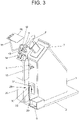
- the last F for holding the shoe uppers C1 is arrayed on a support that anchors the last, positioned on an inclined surface 7 on the upper part of the equipment, with a buffer-stop at the front of the last F for holding the heel 8 which has vertical height regulation through pivoting 9 on a support 10 and with horizontal proximity through displacement of this support 10, positioning the pulling device assembly rod closer or further away in order to adapt it to the different footwear sizes to be assembled.
- the machine may be fitted with a device for boots 11, with Clyde regulation, in addition to having a string guide roller 12 at the front of the last F, which is aligned with a string brace 13, attached to a support 14, from which the arm 15 of the protective transparent cover 16 projects.
- the uppers putting on module 3 for putting shoe uppers on to the last F is comprised of a mechanical pneumatic assembly composed of the brace anchoring the actual last, together with a shoehorn and uppers gripper clamp 18, a flexible blade 19 mounted in the structure 20, through which the pulling device 21 of the shoe horn with an adjustable clamp release sensor and with said pulling device 21 adjustable through a slot 33 in the structure.
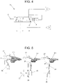
- Fig. 5 the shoehorn pulling device 21 with an adjustable sensor is shown in the middle detail of the figure, where the sensor 23 and the receiver 24 which can be seen attached to the clamp activation assembly, particularly in the middle at 25 where the flexible blade 19 is affixed.
- the string-pulling module 4 is a mechanical pneumatic assembly composed of the above-mentioned support that anchors the last F, with this assembly presented in greater detail in FIG. 6 , where the support functions in association with the support in contact with the shoe uppers C1 and the string guide roller 12; it also encompasses a string gripper clamp 27, in addition to the above-mentioned buffer-stop 8 for holding the heel, with vertical height and horizontal proximity regulation, as well as the vertical height 28 and horizontal proximity 29 adjustment system of the complete pulling device assembly, with vertical regulation handled through a sliding handle or knob 30 on a vertical bar 31, and horizontal adjustment through a toothed bar 32 that can slide along a slot 33; it also encompasses the said string guide roller 12, the string brace 13 and the described transparent protection 16; it also encompasses the tightening string-pulling module 4 and the proportional action pedal 6.
- FIG. 6 discloses further details of the pulling device assembly, showing a string-pulling force activator, through a pneumatic cylinder 34 activated by the pedal 6, which operates through an articulated arm 35 alongside the string guide roller 12, also operating through a contact support point with the shoe uppers C1.
- a string-pulling force activator through a pneumatic cylinder 34 activated by the pedal 6, which operates through an articulated arm 35 alongside the string guide roller 12, also operating through a contact support point with the shoe uppers C1.
- the invention may also optionally encompass an assembling and disassembling module 5 made by ISA for assembling and disassembling the mountable shoe last, best shown in FIG. 10 ; the said assembling and disassembling module 5 is intended to allow shoe uppers C1 to be fitted more easily on the last F or to remove an assembled shoe therefrom.
- This assembling and disassembling module 5 does not require a proportional command.
- FIG. 4 shows the direct action pressure valve (force) and flow (speed) 37, with the logic project design and architecture developed for this machine defining the pneumatic valves and activators as elements generating movements and attachments ( FIG. 11 ).
- the invention may encompass an active sensor pneumatic valve installed on the command pedal 6, that serves as a proportional sensor for operator actions, activating the string-pulling force and speed multiplication activator.
- This valve 37 shown in FIG. 4 , has a proportional pressure mechanical activation pin Z, as well as a pressure inflow point P for the system.
- the element A presents the pneumatic flow outlet with pressure and flow proportional to the activation action of Z; the element R represents the return of the working pressure A into the atmosphere, while X is action spring for returning to the rest position.
- the element e indicates the proportional action position, while f F- is the proportional control mid-position and g is the proportional return mid-position of the action.
- FIG. 11 shows the automation of the string-pulling module 4 and the uppers uppers putting on module 3, with this proportional pedal 6 connected to a sequence of three-way valves 38 on the string-pulling module 4, with this assembly functioning with pressure regulators 39, while the pneumatic cylinders 40 handle the activation and control of the string gripper clamp 27.
- the uppers putting on module 3 discloses an activation pneumatic cylinder 41 alongside the uppers gripper clamp 18, with a set of three-way valves 38 and a second tension pressure return pneumatic cylinder 42.
- FIG. 8 shows the electro-pneumatic sensor circuit and the proportional force and speed activator, with an electronic pedal 6B, a logic controller 43 - electronic signal processing module- powering the pedal 6B and that intercommunicate through a proportional pressure transducer 44 - proportional power activation through an electro-pneumatic proportional valve at the pneumatic circuit output 45, presented as an alternative construction solution.
- the string-pulling module 4 has the following operating sequence:
- the results are achieved through the actions performed by the operator, with the force applied to the pedal 6 in order to control the movements performed by the shoe horn pulling device and the string-pulling device, reflected proportionally in the force and speed applied to the machine, depending on the variations needed for each shoe model.
- the module for putting shoe uppers on to the last F is activated by the pedal 6, for tightening the uppers gripper clamp 18 with pre-set force, as well as for the shoe horn traction, with activation force and speed proportional to the pressure used by the operator.
- the string-pulling module 4 is activated by the pedal 6, in order to activate the string gripper clamp 27 and the heel clamp 12 against the shoe upper C1, with pre-set force and for string-pulling, with activation force and speed in proportion to the pressure used by the operator.
- the flow and pressure at A are provided in proportion to the difference between the amount of pressure applied and its reaction.
- an electronic pedal 6B may be used, with digital or analog data outflows, an electronic signal processing module, and proportional power activation through an electro-pneumatic proportional valve and a pneumatic or electric force activator.
- the machine addressed by the invention may consequently be customized for each application, in other words, it may be composed of a housing that holds any one of the independent modules; or may comprise an association of the housing with two or three of the modules, or may also be assembled with the housing and the three modules together.
- the machine addressed by this invention is intended for the high-productivity footwear assembly sectors, using the string-pulling method - stitching the edges with a lasting string. Its main purposes are:
Landscapes
- Footwear And Its Accessory, Manufacturing Method And Apparatuses (AREA)
Claims (16)
- Schuhoberteilbefestigungsmaschine mit Schnürsenkeleinfädelungsvorrichtung, welche ein Schnürsenkeleinfädelungsverfahren für die Massenproduktion verwendet, umfassend ein metallisches Stützgehäuse (1), welches auf einer flachen Basis (2) gestützt ist, wobei die Schuhoberteilbefestigungsmaschine zusätzlich ein Oberteilaufsetzmodul (3) zum Aufsetzen von Schuhoberteilen auf einem Leisten (F) und ein Schnürsenkeleinfädelungsmodul (4) zum Einfädeln von Schnürsenkeln umfasst, wobei das genannte Oberteilaufsetzmodul (3) und das genannte Schnürsenkeleinfädelungsmodul (4) Kraft- und Geschwindigkeitsaktuatoren enthalten, wobei das Oberteilaufsetzmodul (3) und das Schnürsenkeleinfädelungsmodul (4) kombiniert oder einzeln zusammenarbeiten, dadurch gekennzeichnet, dass das Oberteilaufsetzmodul (3) eine mechanische pneumatische Baugruppe umfasst, bestehend aus einer Verankerungsstrebe (17), welche den Leisten (F) verankert, eine Schuhlöffel- und oberteilgreifklammer (18), welche mit einem flexiblen Flügel (19) gekoppelt ist, welcher an einer Struktur (20) befestigt ist, durch welche eine Schuhlöffelzugvorrichtung (21) mit einem einstellbaren Klammerbefreiungssensor seitlich gesehen werden kann, wobei die Schuhlöffelzugvorrichtung (21) durch einen Schlitz (33) in der Struktur einstellbar ist.
- Schuhoberteilbefestigungsmaschine mit Schnürsenkeleinfädelungsvorrichtung nach Anspruch 1, zusätzlich umfassend ein Montage- und Demontagemodul (5) zum Montieren und Demontieren eines befestigbaren Schuhleistens, wobei das Oberteilaufsetzmodul (3), das Schnürsenkeleinfädelungsmodul (4) und das genannte Montage- und Demontagemodul (5) alle kombiniert zusammenarbeiten, oder das Oberteilaufsetzmodul (3) mit dem Montage- und Demontagemodul (5) zusammenarbeitet, oder das Schnürsenkeleinfädelungsmodul (4) mit dem Montage- und Demontagemodul (5) zusammenarbeitet.
- Schuhoberteilbefestigungsmaschine mit Schnürsenkeleinfädelungsvorrichtung nach Anspruch 1 oder 2, wobei das Oberteilaufsetzmodul (3) und das Schnürsenkeleinfädelungsmodul (4) mit einem Pedal (6) mit einer doppelten Anlaufsteuerung (Ein/Aus) und einer proportionalen Kraft- und Geschwindigkeitssteuerung ausgerüstet sind.
- Schuhoberteilbefestigungsmaschine mit Schnürsenkeleinfädelungsvorrichtung nach Anspruch 1 oder 2, wobei der Leisten (F) für die Schuhoberteile (C1) auf einer Stütze angeordnet ist, welche den Leisten verankert, positioniert auf einer geneigten Fläche (7) auf einem oberen Teil der Apparatur, mit einem Pufferanschlag im vorderen Bereich vom Leisten (F) zum Halten eines Wulstes (8), welcher eine vertikale Höhenverstellung (9) durch Verschwenkung auf einer Stütze (10) und mit horizontaler Nähe durch Verlagerung auf dieser Stütze (10) aufweist.
- Schuhoberteilbefestigungsmaschine mit Schnürsenkeleinfädelungsvorrichtung nach Anspruch 1 oder 2, wobei, vor dem Leisten (F) eine Schnürsenkelführungsrolle (12) enthalten ist, welche mit einer Schnürsenkelstrebe (13) ausgerichtet ist, mit einer Stütze (14) verbunden, aus welcher ein Arm (15) eines durchsichtigen Schutzdeckels (16) hervorsteht.
- Schuhoberteilbefestigungsmaschine mit Schnürsenkeleinfädelungsvorrichtung nach Anspruch 1, wobei die Schuhlöffelzugvorrichtung (21) einen einstellbaren Sensor beinhaltet, welcher ein Sensor (23) und einen Empfänger (24) enthält, welche mit der Klammeraktivierungsbaugruppe verbunden zu sehen sind, insbesondere in der Mitte (25), wo der flexible Flügel (19) fixiert ist.
- Schuhoberteilbefestigungsmaschine mit Schnürsenkeleinfädelungsvorrichtung nach den Ansprüchen 4 und 5, wobei das Schnürsenkeleinfädelungsmodul (4) eine mechanische pneumatische Baugruppe ist, bestehend aus einer Stütze, welche den Leisten (F) verankert, wobei die genannte Stütze mit der Stütze in Kontakt mit den Schuhoberteilen (26) und der Schnürsenkelführungsrolle (12) zusammenarbeitet; sie umfasst auch eine Schnürsenkelgreifklammer (27) zusätzlich zum zuvor erwähnten Pufferanschlag (8) zum Halten des Wulstes, mit einer vertikalen Höhen- und horizontalen Näheverstellung, sowie einem vertikalen Höhen- und horizontalen Näheeinstellungssystem (28, 29) des gesamten Schnürsenkeleinfädelungsmoduls (4).
- Schuhoberteilbefestigungsmaschine mit Schnürsenkeleinfädelungsvorrichtung nach Anspruch 7, wobei die vertikale Verstellung der gesamten Zugvorrichtungsbaugruppe durch einen gleitenden Griff oder Knopf (30) auf einer vertikalen Stange (31), und eine horizontale Einstellung durch eine Zahnstange (32), welche entlang eines Schlitzes (33) gleiten kann, bedient werden kann; sie umfasst auch die genannte Schnürsenkelführungsrolle (12), die Schnürsenkelstrebe (13) und den beschrieben durchsichtigen Schutz (16); sie umfasst auch das Straffungsmodul (4) und das proportionale Betätigungspedal (6).
- Schuhoberteilbefestigungsmaschine mit Schnürsenkeleinfädelungsvorrichtung nach Anspruch 8, wobei das Schnürsenkeleinfädelungsmodul (4) einen Schnürsenkeleinfädelungskraftaktuator umfasst, durch einen vom Pedal (6) aktivierten pneumatischen Zylinder (34), welcher durch einen gelenkigen Arm (35) längsseits der Schnürsenkelführungsrolle (12) funktioniert und auch durch einen Kontaktstützpunkt mit den Schuhoberteilen funktioniert.
- Schuhoberteilbefestigungsmaschine mit Schnürsenkeleinfädelungsvorrichtung nach Anspruch 9, wobei der Schnürsenkeleinfädelungskraftauslöser eine lineare Bewegung aufweist.
- Schuhoberteilbefestigungsmaschine mit Schnürsenkeleinfädelungsvorrichtung nach Anspruch 1, wobei ein Proportionalventil (37) mit direkter Wirkung für Druck und Durchfluss mit dem Schnürsenkelstraffungssystem und dem Schuhlöffel für die Oberteilgreifklammer (18) zusammenarbeitet.
- Schuhoberteilbefestigungsmaschine mit Schnürsenkeleinfädelungsvorrichtung nach Anspruch 1 oder 2, wobei sie ein Proportionalventil (37) mit einem mechanischen Aktivierungsstift (Z) mit proportionalem Druck, sowie einem Druckzulaufpunkt (P) für das System aufweist, während ein Element (A) den pneumatischen Durchflussauslass mit zur Aktivierungswirkung des Aktivierungsstifts (Z) proportionalem Druck und Durchfluss aufweist; ein Element (R) stellt die Rückkehr des Arbeitsdruckes (A) in die Atmosphäre dar, während (X) eine Betätigungsfeder für die Rückkehr zur Ruhestellung ist; schließlich, ein erstes Element (e) zeigt die proportionale Betätigungsstellung an, während ein zweites Element (f) eine proportionale Steuerungsmittelstellung ist und ein drittes Element (g) eine proportionale Rückkehrmittelstellung der Betätigung ist.
- Schuhoberteilbefestigungsmaschine mit Schnürsenkeleinfädelungsvorrichtung nach Anspruch 1, wobei sie eine pneumatische Schaltung mit einem Sensor und einem proportionalen Kraft- und Geschwindigkeitsauslöser zum Steuern des Oberteilaufsetzmoduls (3) und des Schnürsenkeleinfädelungsmoduls (4) aufweist.
- Schuhoberteilbefestigungsmaschine mit Schnürsenkeleinfädelungsvorrichtung nach den Ansprüchen 7 und 13, zusätzlich umfassend die Automatisierung des Schnürsenkeleinfädelungsmoduls (4) und des Oberteilaufsetzmoduls (3), welche das proportionale Pedal (6) enthält, an einer Sequenz von Dreiwegeventilen (38) angeschlossen, mit Druckreglern (39) funktionierend, was auch eine Einstellungssteuerung erlaubt, welche die maximale Zugfestigkeit der Schnürsenkel beschränkt, während die pneumatischen Zylinder (40) die Aktivierung und Steuerung der Schnürsenkelgreifklammer bedienen; während das Oberteilaufsetzmodul (3) einen pneumatischen Aktivierungszylinder (41) längsseits der Oberteilgreifklammer (18), mit einem Satz von Dreiwegeventilen (38) und einem zweiten pneumatischen Spannung-Druck-Rückkehrzylinder (42), aufweist.
- Schuhoberteilbefestigungsmaschine mit Schnürsenkeleinfädelungsvorrichtung nach Anspruch 1 oder 2, zusätzlich umfassend eine elektropneumatische Schaltung aus Sensor und proportionalem Kraft- und Geschwindigkeitsaktuator mittels eines elektronischen Pedals (6B), eine Logiksteuerung (43) (elektronisches Signalverarbeitungsmodul), welche das Pedal (6B) versorgt, und welche durch einen proportionalen Druckwandler (44) (proportionale Leistungsaktivierung durch ein elektropneumatisches Proportionalventil) an einem Auslass der pneumatischen Schaltung (45) in gegenseitiger Verbindung stehen.
- Schuhoberteilbefestigungsmaschine mit Schnürsenkeleinfädelungsvorrichtung nach Anspruch 1 oder 2, zusätzlich umfassend eine Maschine, welche eine Vorrichtung für Stiefel (11), mit Höhenverstellung, hält.
Applications Claiming Priority (2)
| Application Number | Priority Date | Filing Date | Title |
|---|---|---|---|
| BR102015133570 | 2015-06-09 | ||
| PCT/BR2015/050115 WO2016197213A1 (pt) | 2015-06-09 | 2015-08-10 | Máquina para montagem de cabedal com tracionador de cordões |
Publications (3)
| Publication Number | Publication Date |
|---|---|
| EP3308668A1 EP3308668A1 (de) | 2018-04-18 |
| EP3308668A4 EP3308668A4 (de) | 2019-03-06 |
| EP3308668B1 true EP3308668B1 (de) | 2022-04-06 |
Family
ID=61597844
Family Applications (1)
| Application Number | Title | Priority Date | Filing Date |
|---|---|---|---|
| EP15894523.8A Active EP3308668B1 (de) | 2015-06-09 | 2015-08-10 | Schuhoberteilbefestigungsmaschine mit schnürsenkeleinfädelungshilfe |
Country Status (3)
| Country | Link |
|---|---|
| EP (1) | EP3308668B1 (de) |
| ES (1) | ES2919123T3 (de) |
| PT (1) | PT3308668T (de) |
Families Citing this family (1)
| Publication number | Priority date | Publication date | Assignee | Title |
|---|---|---|---|---|
| CN115012126B (zh) * | 2022-06-06 | 2024-11-12 | 池州市谦跃信息技术有限公司 | 一种休闲鞋的生产设备及其使用方法 |
Family Cites Families (4)
| Publication number | Priority date | Publication date | Assignee | Title |
|---|---|---|---|---|
| US1150804A (en) * | 1914-11-02 | 1915-08-17 | United Shoe Machinery Ab | Relasting-machine. |
| US3778856A (en) * | 1971-11-05 | 1973-12-18 | Salient Eng Ltd | String lasting |
| JPS5020853Y1 (de) * | 1974-04-15 | 1975-06-24 | ||
| CA2073514A1 (en) * | 1990-11-09 | 1992-05-10 | Howard A. Gonchar | Molded sole shoe assembling device |
-
2015
- 2015-08-10 EP EP15894523.8A patent/EP3308668B1/de active Active
- 2015-08-10 PT PT158945238T patent/PT3308668T/pt unknown
- 2015-08-10 ES ES15894523T patent/ES2919123T3/es active Active
Also Published As
| Publication number | Publication date |
|---|---|
| ES2919123T3 (es) | 2022-07-22 |
| EP3308668A1 (de) | 2018-04-18 |
| EP3308668A4 (de) | 2019-03-06 |
| PT3308668T (pt) | 2022-07-11 |
Similar Documents
| Publication | Publication Date | Title |
|---|---|---|
| US10716365B2 (en) | Shoe upper mounting machine with string lasting means | |
| US3972086A (en) | Machine for assembling shoe uppers directly on assembly forms | |
| CN102264973B (zh) | 刺绣机用被刺绣物夹持单元及包括该夹持单元的刺绣机 | |
| EP2337675B1 (de) | Fixierungs- und montagearmatur zur schuhherstellung | |
| EP3308668A1 (de) | Schuhoberteilbefestigungsmaschine mit schnürsenkeleinfädelungshilfe | |
| GB2172190A (en) | Control of pressure members in a side-lasting machine | |
| CN110461184B (zh) | 鞋线牵引组件及其在鞋线拉拔器中的应用方法 | |
| JPH0698055B2 (ja) | ヒールくせつけ機 | |
| CN212545885U (zh) | 一种真空无模成型压底机的夹紧装置 | |
| US4407033A (en) | Combination toe and side lasting machine | |
| EP1498042B1 (de) | Maschine zur Herstellung von Schuhwerken | |
| GB2114868A (en) | Gripper assembly | |
| CN208523910U (zh) | 一种后帮预定型机 | |
| US3096531A (en) | Heel end assembling and backpart molding machine | |
| CN108209053B (zh) | 一种缝线鞋匹配帮面拉伸力的鞋帮成型方法 | |
| EP0601772B1 (de) | Maschine zum Zwicken der Fersenbereiche von Schuhen | |
| US412467A (en) | john cave | |
| US97944A (en) | Improved boot-crimper | |
| CN2332222Y (zh) | 半自动绷楦机 | |
| US2856620A (en) | Toe forming machines | |
| CN109043741A (zh) | 一种制鞋用自动贴压底机 | |
| US117627A (en) | Improvement in apparatus for crimping the stiffenings of boots and shoes | |
| US4461101A (en) | Molded shanks | |
| CN209058212U (zh) | 拆装式的鞋帮定位装置 | |
| US700332A (en) | Pulling-over machine. |
Legal Events
| Date | Code | Title | Description |
|---|---|---|---|
| STAA | Information on the status of an ep patent application or granted ep patent |
Free format text: STATUS: THE INTERNATIONAL PUBLICATION HAS BEEN MADE |
|
| PUAI | Public reference made under article 153(3) epc to a published international application that has entered the european phase |
Free format text: ORIGINAL CODE: 0009012 |
|
| STAA | Information on the status of an ep patent application or granted ep patent |
Free format text: STATUS: REQUEST FOR EXAMINATION WAS MADE |
|
| 17P | Request for examination filed |
Effective date: 20180103 |
|
| AK | Designated contracting states |
Kind code of ref document: A1 Designated state(s): AL AT BE BG CH CY CZ DE DK EE ES FI FR GB GR HR HU IE IS IT LI LT LU LV MC MK MT NL NO PL PT RO RS SE SI SK SM TR |
|
| AX | Request for extension of the european patent |
Extension state: BA ME |
|
| DAV | Request for validation of the european patent (deleted) | ||
| DAX | Request for extension of the european patent (deleted) | ||
| A4 | Supplementary search report drawn up and despatched |
Effective date: 20190206 |
|
| RIC1 | Information provided on ipc code assigned before grant |
Ipc: A43D 11/00 20060101ALI20190128BHEP Ipc: A43D 15/00 20060101AFI20190128BHEP Ipc: A43D 21/00 20060101ALI20190128BHEP Ipc: A43D 3/12 20060101ALI20190128BHEP |
|
| REG | Reference to a national code |
Ref country code: DE Ref legal event code: R079 Ref document number: 602015078129 Country of ref document: DE Free format text: PREVIOUS MAIN CLASS: A43D0015000000 Ipc: A43D0013000000 |
|
| GRAP | Despatch of communication of intention to grant a patent |
Free format text: ORIGINAL CODE: EPIDOSNIGR1 |
|
| STAA | Information on the status of an ep patent application or granted ep patent |
Free format text: STATUS: GRANT OF PATENT IS INTENDED |
|
| RIC1 | Information provided on ipc code assigned before grant |
Ipc: A43D 21/00 20060101ALI20211018BHEP Ipc: A43D 15/00 20060101ALI20211018BHEP Ipc: A43D 13/00 20060101AFI20211018BHEP |
|
| INTG | Intention to grant announced |
Effective date: 20211109 |
|
| GRAS | Grant fee paid |
Free format text: ORIGINAL CODE: EPIDOSNIGR3 |
|
| GRAA | (expected) grant |
Free format text: ORIGINAL CODE: 0009210 |
|
| STAA | Information on the status of an ep patent application or granted ep patent |
Free format text: STATUS: THE PATENT HAS BEEN GRANTED |
|
| AK | Designated contracting states |
Kind code of ref document: B1 Designated state(s): AL AT BE BG CH CY CZ DE DK EE ES FI FR GB GR HR HU IE IS IT LI LT LU LV MC MK MT NL NO PL PT RO RS SE SI SK SM TR |
|
| REG | Reference to a national code |
Ref country code: GB Ref legal event code: FG4D |
|
| REG | Reference to a national code |
Ref country code: CH Ref legal event code: EP |
|
| REG | Reference to a national code |
Ref country code: AT Ref legal event code: REF Ref document number: 1480471 Country of ref document: AT Kind code of ref document: T Effective date: 20220415 |
|
| REG | Reference to a national code |
Ref country code: IE Ref legal event code: FG4D |
|
| REG | Reference to a national code |
Ref country code: DE Ref legal event code: R096 Ref document number: 602015078129 Country of ref document: DE |
|
| REG | Reference to a national code |
Ref country code: PT Ref legal event code: SC4A Ref document number: 3308668 Country of ref document: PT Date of ref document: 20220711 Kind code of ref document: T Free format text: AVAILABILITY OF NATIONAL TRANSLATION Effective date: 20220704 |
|
| REG | Reference to a national code |
Ref country code: ES Ref legal event code: FG2A Ref document number: 2919123 Country of ref document: ES Kind code of ref document: T3 Effective date: 20220722 |
|
| REG | Reference to a national code |
Ref country code: LT Ref legal event code: MG9D |
|
| REG | Reference to a national code |
Ref country code: NL Ref legal event code: MP Effective date: 20220406 |
|
| REG | Reference to a national code |
Ref country code: AT Ref legal event code: MK05 Ref document number: 1480471 Country of ref document: AT Kind code of ref document: T Effective date: 20220406 |
|
| PG25 | Lapsed in a contracting state [announced via postgrant information from national office to epo] |
Ref country code: NL Free format text: LAPSE BECAUSE OF FAILURE TO SUBMIT A TRANSLATION OF THE DESCRIPTION OR TO PAY THE FEE WITHIN THE PRESCRIBED TIME-LIMIT Effective date: 20220406 |
|
| PG25 | Lapsed in a contracting state [announced via postgrant information from national office to epo] |
Ref country code: SE Free format text: LAPSE BECAUSE OF FAILURE TO SUBMIT A TRANSLATION OF THE DESCRIPTION OR TO PAY THE FEE WITHIN THE PRESCRIBED TIME-LIMIT Effective date: 20220406 Ref country code: NO Free format text: LAPSE BECAUSE OF FAILURE TO SUBMIT A TRANSLATION OF THE DESCRIPTION OR TO PAY THE FEE WITHIN THE PRESCRIBED TIME-LIMIT Effective date: 20220706 Ref country code: LT Free format text: LAPSE BECAUSE OF FAILURE TO SUBMIT A TRANSLATION OF THE DESCRIPTION OR TO PAY THE FEE WITHIN THE PRESCRIBED TIME-LIMIT Effective date: 20220406 Ref country code: HR Free format text: LAPSE BECAUSE OF FAILURE TO SUBMIT A TRANSLATION OF THE DESCRIPTION OR TO PAY THE FEE WITHIN THE PRESCRIBED TIME-LIMIT Effective date: 20220406 Ref country code: GR Free format text: LAPSE BECAUSE OF FAILURE TO SUBMIT A TRANSLATION OF THE DESCRIPTION OR TO PAY THE FEE WITHIN THE PRESCRIBED TIME-LIMIT Effective date: 20220707 Ref country code: FI Free format text: LAPSE BECAUSE OF FAILURE TO SUBMIT A TRANSLATION OF THE DESCRIPTION OR TO PAY THE FEE WITHIN THE PRESCRIBED TIME-LIMIT Effective date: 20220406 Ref country code: BG Free format text: LAPSE BECAUSE OF FAILURE TO SUBMIT A TRANSLATION OF THE DESCRIPTION OR TO PAY THE FEE WITHIN THE PRESCRIBED TIME-LIMIT Effective date: 20220706 Ref country code: AT Free format text: LAPSE BECAUSE OF FAILURE TO SUBMIT A TRANSLATION OF THE DESCRIPTION OR TO PAY THE FEE WITHIN THE PRESCRIBED TIME-LIMIT Effective date: 20220406 |
|
| PG25 | Lapsed in a contracting state [announced via postgrant information from national office to epo] |
Ref country code: RS Free format text: LAPSE BECAUSE OF FAILURE TO SUBMIT A TRANSLATION OF THE DESCRIPTION OR TO PAY THE FEE WITHIN THE PRESCRIBED TIME-LIMIT Effective date: 20220406 Ref country code: PL Free format text: LAPSE BECAUSE OF FAILURE TO SUBMIT A TRANSLATION OF THE DESCRIPTION OR TO PAY THE FEE WITHIN THE PRESCRIBED TIME-LIMIT Effective date: 20220406 Ref country code: LV Free format text: LAPSE BECAUSE OF FAILURE TO SUBMIT A TRANSLATION OF THE DESCRIPTION OR TO PAY THE FEE WITHIN THE PRESCRIBED TIME-LIMIT Effective date: 20220406 Ref country code: IS Free format text: LAPSE BECAUSE OF FAILURE TO SUBMIT A TRANSLATION OF THE DESCRIPTION OR TO PAY THE FEE WITHIN THE PRESCRIBED TIME-LIMIT Effective date: 20220806 |
|
| REG | Reference to a national code |
Ref country code: DE Ref legal event code: R097 Ref document number: 602015078129 Country of ref document: DE |
|
| PG25 | Lapsed in a contracting state [announced via postgrant information from national office to epo] |
Ref country code: SM Free format text: LAPSE BECAUSE OF FAILURE TO SUBMIT A TRANSLATION OF THE DESCRIPTION OR TO PAY THE FEE WITHIN THE PRESCRIBED TIME-LIMIT Effective date: 20220406 Ref country code: SK Free format text: LAPSE BECAUSE OF FAILURE TO SUBMIT A TRANSLATION OF THE DESCRIPTION OR TO PAY THE FEE WITHIN THE PRESCRIBED TIME-LIMIT Effective date: 20220406 Ref country code: RO Free format text: LAPSE BECAUSE OF FAILURE TO SUBMIT A TRANSLATION OF THE DESCRIPTION OR TO PAY THE FEE WITHIN THE PRESCRIBED TIME-LIMIT Effective date: 20220406 Ref country code: EE Free format text: LAPSE BECAUSE OF FAILURE TO SUBMIT A TRANSLATION OF THE DESCRIPTION OR TO PAY THE FEE WITHIN THE PRESCRIBED TIME-LIMIT Effective date: 20220406 Ref country code: DK Free format text: LAPSE BECAUSE OF FAILURE TO SUBMIT A TRANSLATION OF THE DESCRIPTION OR TO PAY THE FEE WITHIN THE PRESCRIBED TIME-LIMIT Effective date: 20220406 Ref country code: CZ Free format text: LAPSE BECAUSE OF FAILURE TO SUBMIT A TRANSLATION OF THE DESCRIPTION OR TO PAY THE FEE WITHIN THE PRESCRIBED TIME-LIMIT Effective date: 20220406 |
|
| PLBE | No opposition filed within time limit |
Free format text: ORIGINAL CODE: 0009261 |
|
| STAA | Information on the status of an ep patent application or granted ep patent |
Free format text: STATUS: NO OPPOSITION FILED WITHIN TIME LIMIT |
|
| 26N | No opposition filed |
Effective date: 20230110 |
|
| PG25 | Lapsed in a contracting state [announced via postgrant information from national office to epo] |
Ref country code: MC Free format text: LAPSE BECAUSE OF FAILURE TO SUBMIT A TRANSLATION OF THE DESCRIPTION OR TO PAY THE FEE WITHIN THE PRESCRIBED TIME-LIMIT Effective date: 20220406 Ref country code: AL Free format text: LAPSE BECAUSE OF FAILURE TO SUBMIT A TRANSLATION OF THE DESCRIPTION OR TO PAY THE FEE WITHIN THE PRESCRIBED TIME-LIMIT Effective date: 20220406 |
|
| REG | Reference to a national code |
Ref country code: CH Ref legal event code: PL |
|
| GBPC | Gb: european patent ceased through non-payment of renewal fee |
Effective date: 20220810 |
|
| PG25 | Lapsed in a contracting state [announced via postgrant information from national office to epo] |
Ref country code: LU Free format text: LAPSE BECAUSE OF NON-PAYMENT OF DUE FEES Effective date: 20220810 Ref country code: LI Free format text: LAPSE BECAUSE OF NON-PAYMENT OF DUE FEES Effective date: 20220831 Ref country code: CH Free format text: LAPSE BECAUSE OF NON-PAYMENT OF DUE FEES Effective date: 20220831 |
|
| REG | Reference to a national code |
Ref country code: BE Ref legal event code: MM Effective date: 20220831 |
|
| PG25 | Lapsed in a contracting state [announced via postgrant information from national office to epo] |
Ref country code: SI Free format text: LAPSE BECAUSE OF FAILURE TO SUBMIT A TRANSLATION OF THE DESCRIPTION OR TO PAY THE FEE WITHIN THE PRESCRIBED TIME-LIMIT Effective date: 20220406 |
|
| P01 | Opt-out of the competence of the unified patent court (upc) registered |
Effective date: 20230518 |
|
| PG25 | Lapsed in a contracting state [announced via postgrant information from national office to epo] |
Ref country code: IE Free format text: LAPSE BECAUSE OF NON-PAYMENT OF DUE FEES Effective date: 20220810 Ref country code: FR Free format text: LAPSE BECAUSE OF NON-PAYMENT OF DUE FEES Effective date: 20220831 |
|
| PG25 | Lapsed in a contracting state [announced via postgrant information from national office to epo] |
Ref country code: BE Free format text: LAPSE BECAUSE OF NON-PAYMENT OF DUE FEES Effective date: 20220831 |
|
| PG25 | Lapsed in a contracting state [announced via postgrant information from national office to epo] |
Ref country code: GB Free format text: LAPSE BECAUSE OF NON-PAYMENT OF DUE FEES Effective date: 20220810 |
|
| PG25 | Lapsed in a contracting state [announced via postgrant information from national office to epo] |
Ref country code: HU Free format text: LAPSE BECAUSE OF FAILURE TO SUBMIT A TRANSLATION OF THE DESCRIPTION OR TO PAY THE FEE WITHIN THE PRESCRIBED TIME-LIMIT; INVALID AB INITIO Effective date: 20150810 |
|
| PG25 | Lapsed in a contracting state [announced via postgrant information from national office to epo] |
Ref country code: CY Free format text: LAPSE BECAUSE OF FAILURE TO SUBMIT A TRANSLATION OF THE DESCRIPTION OR TO PAY THE FEE WITHIN THE PRESCRIBED TIME-LIMIT Effective date: 20220406 |
|
| PG25 | Lapsed in a contracting state [announced via postgrant information from national office to epo] |
Ref country code: MK Free format text: LAPSE BECAUSE OF FAILURE TO SUBMIT A TRANSLATION OF THE DESCRIPTION OR TO PAY THE FEE WITHIN THE PRESCRIBED TIME-LIMIT Effective date: 20220406 |
|
| PG25 | Lapsed in a contracting state [announced via postgrant information from national office to epo] |
Ref country code: TR Free format text: LAPSE BECAUSE OF FAILURE TO SUBMIT A TRANSLATION OF THE DESCRIPTION OR TO PAY THE FEE WITHIN THE PRESCRIBED TIME-LIMIT Effective date: 20220406 |
|
| PG25 | Lapsed in a contracting state [announced via postgrant information from national office to epo] |
Ref country code: MT Free format text: LAPSE BECAUSE OF FAILURE TO SUBMIT A TRANSLATION OF THE DESCRIPTION OR TO PAY THE FEE WITHIN THE PRESCRIBED TIME-LIMIT Effective date: 20220406 |
|
| PG25 | Lapsed in a contracting state [announced via postgrant information from national office to epo] |
Ref country code: BG Free format text: LAPSE BECAUSE OF FAILURE TO SUBMIT A TRANSLATION OF THE DESCRIPTION OR TO PAY THE FEE WITHIN THE PRESCRIBED TIME-LIMIT Effective date: 20220406 |
|
| PG25 | Lapsed in a contracting state [announced via postgrant information from national office to epo] |
Ref country code: BG Free format text: LAPSE BECAUSE OF FAILURE TO SUBMIT A TRANSLATION OF THE DESCRIPTION OR TO PAY THE FEE WITHIN THE PRESCRIBED TIME-LIMIT Effective date: 20220406 |
|
| PGFP | Annual fee paid to national office [announced via postgrant information from national office to epo] |
Ref country code: ES Payment date: 20250903 Year of fee payment: 11 Ref country code: PT Payment date: 20250819 Year of fee payment: 11 |
|
| PGFP | Annual fee paid to national office [announced via postgrant information from national office to epo] |
Ref country code: DE Payment date: 20250827 Year of fee payment: 11 |
|
| PGFP | Annual fee paid to national office [announced via postgrant information from national office to epo] |
Ref country code: IT Payment date: 20250820 Year of fee payment: 11 |