EP3308620A1 - Cutter assembly with knife guard and knife guard holder - Google Patents
Cutter assembly with knife guard and knife guard holder Download PDFInfo
- Publication number
- EP3308620A1 EP3308620A1 EP17196337.4A EP17196337A EP3308620A1 EP 3308620 A1 EP3308620 A1 EP 3308620A1 EP 17196337 A EP17196337 A EP 17196337A EP 3308620 A1 EP3308620 A1 EP 3308620A1
- Authority
- EP
- European Patent Office
- Prior art keywords
- wedge
- knife guard
- knife
- holder
- shaped
- Prior art date
- Legal status (The legal status is an assumption and is not a legal conclusion. Google has not performed a legal analysis and makes no representation as to the accuracy of the status listed.)
- Granted
Links
Images




Classifications
-
- A—HUMAN NECESSITIES
- A01—AGRICULTURE; FORESTRY; ANIMAL HUSBANDRY; HUNTING; TRAPPING; FISHING
- A01D—HARVESTING; MOWING
- A01D34/00—Mowers; Mowing apparatus of harvesters
- A01D34/01—Mowers; Mowing apparatus of harvesters characterised by features relating to the type of cutting apparatus
- A01D34/02—Mowers; Mowing apparatus of harvesters characterised by features relating to the type of cutting apparatus having reciprocating cutters
- A01D34/13—Cutting apparatus
- A01D34/16—Guides for the knife-bar in the ledger-plate
-
- A—HUMAN NECESSITIES
- A01—AGRICULTURE; FORESTRY; ANIMAL HUSBANDRY; HUNTING; TRAPPING; FISHING
- A01D—HARVESTING; MOWING
- A01D34/00—Mowers; Mowing apparatus of harvesters
- A01D34/01—Mowers; Mowing apparatus of harvesters characterised by features relating to the type of cutting apparatus
- A01D34/015—Cutting mechanisms not covered by another group
-
- A—HUMAN NECESSITIES
- A01—AGRICULTURE; FORESTRY; ANIMAL HUSBANDRY; HUNTING; TRAPPING; FISHING
- A01D—HARVESTING; MOWING
- A01D34/00—Mowers; Mowing apparatus of harvesters
- A01D34/01—Mowers; Mowing apparatus of harvesters characterised by features relating to the type of cutting apparatus
- A01D34/02—Mowers; Mowing apparatus of harvesters characterised by features relating to the type of cutting apparatus having reciprocating cutters
- A01D34/13—Cutting apparatus
- A01D34/18—Guard fingers; Ledger-plates
-
- A—HUMAN NECESSITIES
- A01—AGRICULTURE; FORESTRY; ANIMAL HUSBANDRY; HUNTING; TRAPPING; FISHING
- A01D—HARVESTING; MOWING
- A01D34/00—Mowers; Mowing apparatus of harvesters
- A01D34/01—Mowers; Mowing apparatus of harvesters characterised by features relating to the type of cutting apparatus
- A01D34/02—Mowers; Mowing apparatus of harvesters characterised by features relating to the type of cutting apparatus having reciprocating cutters
- A01D34/03—Mowers; Mowing apparatus of harvesters characterised by features relating to the type of cutting apparatus having reciprocating cutters mounted on a vehicle, e.g. a tractor, or drawn by an animal or a vehicle
- A01D34/04—Mowers; Mowing apparatus of harvesters characterised by features relating to the type of cutting apparatus having reciprocating cutters mounted on a vehicle, e.g. a tractor, or drawn by an animal or a vehicle with cutters at the front
-
- A—HUMAN NECESSITIES
- A01—AGRICULTURE; FORESTRY; ANIMAL HUSBANDRY; HUNTING; TRAPPING; FISHING
- A01D—HARVESTING; MOWING
- A01D34/00—Mowers; Mowing apparatus of harvesters
- A01D34/01—Mowers; Mowing apparatus of harvesters characterised by features relating to the type of cutting apparatus
- A01D34/02—Mowers; Mowing apparatus of harvesters characterised by features relating to the type of cutting apparatus having reciprocating cutters
- A01D34/13—Cutting apparatus
- A01D34/14—Knife-bars
-
- A—HUMAN NECESSITIES
- A01—AGRICULTURE; FORESTRY; ANIMAL HUSBANDRY; HUNTING; TRAPPING; FISHING
- A01D—HARVESTING; MOWING
- A01D2101/00—Lawn-mowers
Definitions
- Cutter assemblies are utilized in a wide variety of equipment for cutting various plants and growing medium.
- cutter assemblies are found in combine harvesters, choppers, haybines, sicklebars and other agricultural implements.
- Such cutter assemblies may include knife guards that guide sliding and reciprocating movement of a cutting knife.
- repair and replacement of knife guards is often difficult. Such repair or replacement may require complete disassembly of many components of the implement. For example, repair or replacement of a knife guard may frequently require the removal of bolts along with skid shoes. The removal of these components may require the use of tools. When such repair or replacement occurs in the field, the required tools may not be available or such parts, when removed, may become lost.
- the example cutter assemblies facilitate removal and separation of knife guards from the cutter assembly with minimal use of or no use of tools.
- the example cutter assemblies further facilitate removal and separation of knife guards from the cutter assembly with a minimal number of fasteners or no fasteners or components, reducing the likelihood that such removed fasteners or components may be lost in the field.
- the example cutter assemblies further allow existing agricultural and other implements to be modified for their use.
- the example cutter assemblies further provide for the use of less complex, lighter weight and less expensive knife guards.
- an example cutter assembly may include a knife guard holder to be removably connected to a cutter bar, a knife guard an interface between the knife guard holder and the knife guard.
- the knife guard may have a knife channel to slidably guide a cutter knife.
- the interface extends between the knife guard holder and the knife guard to locate and releasably retain the knife guard with respect to the knife guard holder.
- an example knife guard may comprise an integral unitary polymer body, a first metal plate and a second metal plate.
- the polymer body may comprise a bar, a plurality of pointed fingers forwardly projecting from the bar and a plurality of wedge-shaped projections projecting rearwardly from the bar.
- the plurality of wedge-shaped projections are to be received within a corresponding plurality of wedge-shaped cavities.
- At least one of the pointed fingers forms a knife channel.
- the first metal plate may continuously extend across and be secured to the plurality of pointed fingers with the first metal cutter plate forming a floor of the knife channel.
- the second metal plate may be secured to the at least one of the pointed fingers forming the knife channel, wherein the second metal plate forms a ceiling of the knife channel.
- the method may comprise removably mounting a knife guard holder to a cutter bar, wherein the knife guard holder comprising one of wedges and wedge-shaped cavities.
- the method may further comprise mounting a knife guard to the knife guard holder by inserting the other of the wedges and the wedge-shaped cavities of the knife guard into said one of the wedges and wedge-shaped cavities of the knife guard holder.
- FIG. 1 is a perspective view of a portion of an example cutter assembly 20 that facilitates the repair or replacement of a knife guard.
- Cutter assembly comprises knife guard holder 24, knife guard 26 and interface 30 (schematically illustrated).
- Knife guard holder 24 comprises a component that is configured to be removably coupled to a cutter bar, also sometimes referred to as a staff, and that is to further configured to be removably coupled to knife guard 26 by interface 30.
- the phrase “configured to” denotes an actual state of configuration that fundamentally ties the stated function/use to the physical characteristics of the feature proceeding the phrase “configured to”.
- the term “releasably” or “removably” with respect to an attachment or coupling of two structures means that the two structures may be repeatedly connected and disconnected to and from one another without material damage to either of the two structures or their functioning.
- the term "coupled” shall mean the joining of two members directly or indirectly to one another. Such joining may be stationary in nature or movable in nature. Such joining may be achieved with the two members or the two members and any additional intermediate members being integrally formed as a single unitary body with one another or with the two members or the two members and any additional intermediate member being attached to one another. Such joining may be permanent in nature or alternatively may be removable or releasable in nature.
- knife guard holder 26 is configured to be directly coupled to a cutter bar.
- knife cardholder 26 is formed from steel, aluminum or iron.
- Knife guard holder 26 comprises a pair of rings 32 having fastening apertures 34 through which fasteners, such as bolts, may pass and be connected to the cutter bar.
- knife guard holder 26 may comprise other mechanisms for releasable mounting and securing of knife guard holder 26 to a cutter bar or other frame structure of an agricultural implement.
- Knife guard 26 also sometimes referred to as a sickle guard, comprises a device removably mounted to knife guard holder 26 by interface 30 and configured to guide sliding and reciprocating movement of a cutter or knife.
- Knife guard 26 comprises bar 40 and a plurality of forwardly projecting, generally pointed, fingers 42A, 42B and 42C (collectively referred to as fingers 42) having tips or noses 43. Fingers 42 project forwardly from bar 40 in a direction away from holder 24. At least one of fingers 42 comprise a rearwardly facing knife channel 44 that slidably receives portions of a knife, namely, knife sections of the knife.
- the knife channel 44 comprises both a bottom surface or floor 46 and an opposite upper surface or ceiling 48 defined by the finger 42.
- knife guard 26 comprises three fingers 42: a middle or central finger 42A that comprises knife channel 44 and two lateral or side fingers 42B and 42C that are to underlie the knife without projecting over the knife.
- knife guard 26 may have other arrangements of fingers 42.
- knife guard 26 may alternatively comprise a pair of fingers 42 which each of fingers 42 having a configuration similar to finger 42A.
- knife guard 26 may alternatively comprise a pair of fingers 42, with one of fingers 42 being configured similar to finger 42A and with the other of the fingers 42 being configured similar to finger 42C.
- knife guard 26 may comprise more than three fingers 42, wherein the multiple fingers 42 have various combinations of fingers similar to finger 42A and fingers similar to fingers 42B and 42C.
- knife guard 26 is formed from a metal material.
- knife guard 26 is formed from a cast steel, aluminum, iron or various metal alloys.
- knife guard 26 is formed from a ceramic or polymer material.
- knife guard 26 may be formed from a composite glass reinforced polymer.
- knife guard 20 formed from a ceramic or polymer, wherein those portions of knife guard 26 that contact the knife are provided with a metal surface.
- knife guard 26 may comprise a polymer outer body with metal plates that interface with the reciprocating knife.
- knife guard 26 may comprise a polymer outer body with a metal insert or core at least partially encapsulated by the polymer outer body.
- Interface 30 comprises a mechanical interconnection between knife guard holder 24 and knife guard 26.
- Interface 30 locates and retains knife guard 26 relative to knife guard holder 24.
- Interface 30 facilitates removable separation of knife guard holder 24 and knife guard 26.
- interface 30 comprises cooperating portions of both knife guard holder 24 and knife guard 26.
- Interface 30 facilitates a releasable connection of knife controller 24 to knife guard 26 in a fashion so as to reduce or eliminate fasteners and so as to reduce or eliminate reliance upon tools for such disconnection.
- Interface 30 may enable quicker and easier separation of knife guard 26 for repair and/or replacement.
- interface 30 comprises male and female connection portions associated with the knife guard holder 24 and the knife guard 26, wherein the male connection portion mates with the female connection portion to facilitate releasable connection of knife guard holder 24 to knife guard 26.
- the interface comprises male and female connection portions that wedge within one another.
- interface 30 comprises a tapering wedge-shaped projection and a tapering wedge-shaped cavity that receives the projection. The wedge-shaped rejection tapering wedge shaped cavity take primary and secondary loads during operation of cutter assembly 20.
- additional or alternative retaining mechanisms may be employed to secure knife guard 26 to knife guard holder 24.
- the male connection portion may additionally comprise a catch or dovetail that resiliently snaps into a detent or that resiliently snaps behind an edge of the female connection portion.
- interface 30 may comprise a spring pin or quarter turn locking device to releasably secure knife guard 26 to knife cardholder 24.
- the interface 30 may additionally or alternatively utilize magnetic attraction to assist in retaining the connection of knife guard 26 and knife guard holder 24.
- one or both of the male connection portion and the female connection portion may include a magnetized material or magnet.
- One of the male connection portion and the female connection may include a magnetized material or magnet while the other of the male connection portion and the female connection portion comprises a ferrous material.
- the knife guard holder 24 and knife guard 26 may comprise aligned channels that removably receive a retention pin.
- Figure 2 is an exploded perspective view of a portion of another example cutter assembly 120 comprising knife guard holder 24, knife guard 26 and a specific example interface 130.
- Interface 130 comprises tapering wedge-shaped projections 132 and corresponding internally tapering wedge-shaped cavities 134.
- projections 132 and cavities 134 have frustro-conical shapes.
- projections 132 and cavities 134 may have other corresponding tapering wedge-shapes.
- projections 132 and cavities 134 may alternatively have tapering polygonal cross-sectional shapes, such as a flat-top pyramid shape.
- projections 132 are illustrated as being provided as part of knife guard 26, projecting rearwardly from bar 40 while cavities 134 are illustrated as being provided as part of knife guard holder 24, projecting forwardly from rings 32, in other implementations, this relationship may be reversed such that projections 132 extend forwardly from rings 32 of knife guard holder 24 while cavities 134 are formed within or project rearwardly from bar 40.
- Figure 3 is a sectional view, through finger 42A, illustrating interface 130 removably connecting knife guard 26 to knife guard holder 24.
- projections 132 are wedged into cavities 134, inhibiting relative movement therebetween but for movement of knife guard 26 in a forward direction. As the forces imposed upon knife guard 26 during use tend to further move knife guard 26 rearwardly, to the right in the illustrated figure, projections 132 are less likely to become accidentally dislodged from cavities 134.
- Figure 3 further illustrates a variation of knife guard 26, wherein the outer body of knife guard 26 may be formed from a polymer material or a combination of materials that may be susceptible to abrasion wear from a reciprocating knife and wherein portions of knife channel 44 that might otherwise contact and wear against knife are provided with a layer 140, 142 of a different material more resistant to abrasion and/or having a lower coefficient of friction as compared to the other materials of the outer body of knife guard 26.
- layers 141, 142 may comprise metal plates secured to the polymer outer body of knife guard 26.
- such metal plates may be fastened to the remainder of knife guard 26, may be bonded to the remainder of knife guard 26 and/or may be mechanically locked to the remainder of knife guard 26 such as where the remainder of knife guard 26 is molded and encapsulates selected portions of the metal plates.
- layers 141, 142 may comprise a lamination or coating on the remainder of knife guard 26. In such implementations, layers 141, 142 may provide sharp edges that cooperate with the knife to further facilitate cutting.
- Figure 4 is a flow diagram of an example method 200 for assembling a cutter assembly.
- Method 200 facilitates separation of the knife guard from the remainder of an implement with minimal or no use of tools and with minimal or no use of fasteners.
- method 200 is described in the context of being carried out with interface 130 between knife guard holder 24 and knife guard 26, it should be appreciative that method 200 may be carried out with any of the knife guards and knife guard holders, and their respective interfaces, describing this disclosure or other interfaces having similar characteristics. It should further be appreciated that method 200 may be reversed to facilitate removal and separation of knife guard 26 from the remainder of an implement.
- knife guard holder 24 is removably mounted to a cutter bar.
- fasteners are inserted through fasting apertures 34 and connected to portions of the cutter bar.
- Knife guard holder 24 comprises one of wedges 132 and wedge-shaped cavities 134.
- knife guard 26 is mounted to knife guard holder 24 by inserting the other of the wedges and the wedge-shaped cavities of the knife guard into said one of the wedges and wedge-shaped cavities of the knife guard holder.
- wedges 132 of knife guard 26 are inserted into wedge-shaped cavities 134 of knife guard holder 24.
- Figure 5 is a sectional view of a portion of an example cutter assembly 320, wherein the assembled knife guard holder 24 and knife guard 26 are removably connected to one another by yet another example interface 330.
- Those components of cutter assembly 320 which correspond to components of cutter assembly 120 are numbered similarly.
- Interface 330 is similar interface 130 described above in that interface 330 comprises tapering wedge-shaped cavities 134 in which wedges 132 are wedged.
- projections 132 and cavities 134 are additionally lined or coated with layers 332 and 334, respectively.
- layers 332 and 334 form external and internal sleeves that completely surround wedges 132 and the interior surfaces of cavities 134.
- one or both of layers 332 and 334 may only partially extend about the circumference of projections 132 and cavities 134.
- layers 332, 334 are formed from materials different than the adjacent materials of projections 132 and cavity 134 so as to provide abrasion resistance, reducing abrasion.
- layer 322 and 334 are formed from materials different than the adjacent materials of projections 132 and cavity 134 so as to provide enhanced gripping, wherein layers 132 and 134 have a higher relative coefficient of friction with respect to one another as compared to the materials of projections 132 and cavity 134.
- layer 332 and 334 are formed from materials different than the adjacent materials of projections 132 and cavity 134 so as to provide magnetic attraction between projections 132 and knife guard holder 24.
- both of layers 332, 334 may be formed from a magnet or a magnetized material.
- one of layer 332, 334 may be formed from a magnet or a magnetized material of the other of layer 332, 334 is formed from a ferrous material or material that is attracted to the magnet.
- at least portions of wedges 132 may be entirely formed from a ferrous material while cavity 134 comprises the magnet such that layer 332 may be omitted.
- cavity 134 may be entirely formed from a ferrous material while wedges 132 comprise a magnet such that layer 334 may be omitted.
- layer 332 and 334 are provided for magnetic attraction and retention, one or both of layer 332, 334 may be alternatively embedded within the material of wedges 132 or the material of knife guard holder 24 about cavity 134, covered by a thin layer of nonferrous or non-magnetic material.
- holder 24 may be formed from a ferrous material, wherein wedges 132 completely surround and embed an internal magnet.
- Figure 6 illustrates a portion of another example cutter assembly 420 comprising knife guard holder 24, knife guard 26 and another example interface 430.
- Interface 430 utilizes a pair of aligned channels and a retention pin to releasably retain insecure knife guard 26 to knife guard holder 24.
- Those components of cutter assembly 420 which correspond to components of cutter assembly 20 or cutter assembly 120 are numbered similarly.
- Interface 430 comprises extensions 432, cavities 434, and retention pin 436. Extensions 432 rearwardly project from bar 430 and form aligned channels 438. In the example illustrated, extensions 432 have hook or claw-shaped ends that form the aligned channels 438. In other implementations, extensions 432 may alternatively comprise bores, completely surrounded by the material of extensions 432, wherein the bores have interiors forming the aligned channels 438.
- Cavities 434 extend into portions of knife guard holder 24 and correspond to extensions 432 so as to removably receive extensions 432.
- Each of cavities 434 comprise side openings 440 that are aligned with channels 438 when extensions 432 are fully inserted into cavities 434.
- Side openings 440 provide aligned passages through knife guard holder 24 to facilitate insertion of retention pin 436 through each of side openings 440 and through channels 438 to inhibit withdrawal extensions 432 from cavities 434.
- extensions 432 and cavities 434 have cross-sections that do not taper.
- extensions 432 and cavities 434 have tapering cross-sections, further facilitating securement of extensions 432 within cavities 434 by the wedging of extensions 432 within cavities 434.
- Retention pin 436 comprises an elongate shaft or pin configured to slidably pass through opening 440 and channels 438, extending across each of extensions 432 of knife guard 26.
- retention pin 436 comprises a cotter pin.
- retention pin 436 comprises a threaded bolt for use with an associated threaded nut. Removal of retention pin 436 allows extensions 432 to be manually pulled and withdrawn from cavities 434, facilitating separation of knife guard 26 from knife guard holder 24 and the remainder of the implement.
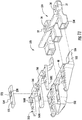
- FIGs 7-13 illustrate a portion of another example cutter assembly 520 comprising knife guard holder 524 and knife guard 526 releasably connected to one another by an interface 530.
- Knife guard holder 524 is similar to knife guard holder 24 described above except that knife guard holder 524 comprises portions of interface 530.
- Knife guard 526 is similar to knife guard 26 in that knife guard 526 comprises fingers 42 formerly projecting from a bar 40, wherein at least one of the fingers 42 comprises a knife channel 44.
- knife guard 526 is specifically illustrated as comprising an outer polymer body 550 and metal inserts 552, 554.
- Figure 11 illustrates metal inserts 552, 554 exploded away from and separated from the outer polymer body 550.
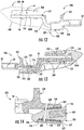
- Figure 8 , 10 and 12 transparently illustrate portions of outer polymeric body 552 illustrate the interrelationship between body 550 and metal inserts 552, 554.
- Figure 13 is a sectional view through finger 42A.
- Outer polymeric body 550 comprise a single integral unitary body form from a polymer or mixture the different polymers.
- outer polymerbody 550 is formed from a material such as a composite glass reinforced polymer, such as a glass reinforced polymer. The polymer material forming body 550 reduces the weight of cutter assembly 520 as well as its cost.
- Outer polymeric body 550 forms bar 40 and each of fingers 42 described above. As shown by Figures 11 and 12 , outer polymer body 550 extends about opposite sides of portions of metal inserts 552, 554 and/or within apertures within metal inserts 552, 554 to retain metal inserts 552, 554 relative to body 550 in at least one direction. As shown by Figure 13 , in one implementation, outer polymer body 550 is molded about metal inserts 552, 554 so as to at least partially encapsulate multiple pairs of opposite sides of metal insert 552 and 554 so as to mechanically lock inserts 552 and 524 in place without the use of adhesives, welding or fasteners.
- polymer body 550 may comprise projections that make within corresponding apertures in inserts 552 and 554 to assist in retaining metal insert 552 and 554 in place.
- insert 552 and 524 may additionally be glued, fuse or fastened to body 550.
- Metal insert 552 comprises a metallic structure formed from a metal such as 1070 steel or various alloys.
- Metal insert 552 comprises a metal plates 560A, 560B and 560C (collectively referred to as metal plates 560) and extensions 562.
- Metal plates 560A, 560B and 560C extend above underlying portions of fingers 42A, 42B and 42C, respectively, providing metal layers upon which the knife of the cutter assembly rides.
- Metal plate 560A forms the lower surface or floor 46 of knife channel 44.
- Metal plates 560 further provide sharp metal edges, such as edges 564 and 556 that interact with such knives to facilitate cutting of the plants.
- metal plates 560 comprise apertures 566 through which the polymer material of body 550 may extend and be captured.
- each of metal plates 560 comprises at least one downwardly extending tang 568 which is completely encapsulated and surrounded by the polymer material of body 550. Such encapsulation further reliably secures and retains insert 552 in place with respect to body 550.
- tangs 568 and/or apertures 566 may be omitted.
- Extensions 562 extend rearwardly from plates 560 and are completely encapsulated by polymer body 550. In the example illustrated, extensions 562 are completely encapsulated by those portions of polymer body 550 forming part of interface 530. Extensions 562 different and rigidify those portions of polymer body 550 forming part of interface 530. In the example illustrated, extensions 562 are integrally formed as a single unitary body with plates 560. In one implementation, extensions 562 and plates 560 are formed from a stamped and deformed sheet of metal. In other implementations, extensions 562 and plates 560 are formed through casting or molding.
- Metal insert 554 comprises a metal plate secured to central finger 42A above knife channel 44. Metal insert 554 forms an upper surface or ceiling 48 of knife channel 44 and provide services against which the upper surface of the received knife may bear against. Similar to metal plate 560A, metal insert 552 provides sharp wear resistant metal edges, such as edge 568 (shown in Figure 12 ), that interact with such knives to facilitate cutting of the plants.
- metal insert 554 is a separate piece from metal insert 552. Similar to metal insert 552, metal insert 554 comprises apertures 570 through which the polymer material of body 550 may extend and be captured. As illustrated by Figure 13 , metal insert 552 may further comprise at least one upwardly extending tang 572 which is completely encapsulated and surrounded by the polymer material of body 550. Such encapsulation further reliably secures and retains insert 554 in place with respect to body 550. In other implementations, tang 572 and/or apertures 570 may be omitted. In some implementations, metal insert 554 may be bonded, snapped or fastened to body 550. In some implementations, in lieu of being a separate component from insert 552, insert 554 may be integrally formed as part of a single unitary body with insert 552, having a horizontal U shape and extending rearwardly from a front edge of metal plate 560A.
- Interface 530 releasably connects knife guard holder 24 and knife guard 526.
- interface 530 comprises wedges 532, wedge-shaped cavities 534 and catches 536.
- Wedges 532 extend rearwardly from bar 40 and rearwardly taper, having a gradually rearwardly decreasing cross-sectional area.
- wedges 532 are integrally formed as part of a single unitary body with bar 40 and the remainder of polymer body 550.
- wedges 532 surround portions of extensions 562 of metal insert 552. As shown by Figure 13 , extensions 562, along with wedges 532 are received within wedge-shaped cavities 534. As a result, as shown by Figure 13 , the junction 576 of projections 532 and cavities 534 is further stiffened and strengthened by the internal extension 562.
- each wedge 534 has a tapering flat pyramid or tapering trapezoidal cross section shape. In other implementations, each wedge 534 may have a conical or frustro-conical shape similar to projections 132 described above.
- Wedge-shaped cavities 534 extend forwardly from a remainder of knife guard holder 524.
- Wedge-shaped cavities 534 are similar to wedge-shaped cavities 134 described above except that wedge-shaped cavities 534 have internally tapering trapezoidal cross sectional shapes. As indicated above, depending upon the shape of wedges 532, wedge-shaped cavity 534 may have other tapering internal cavity shapes.
- Catch 534 comprise a hook or other projection extending from wedge 532 so as to resiliently snap into a corresponding detent or void within or at the end of the corresponding wedge-shaped cavity 534.
- each catch 534 comprises a dovetail.
- catch 536 contacts and engages an external edge 576 at the end of cavity 534 when wedges 532 have been sufficiently and fully inserted into (and through) cavities 534.
- catches 536 not only retain wedges 532 within cavities 534 to prevent accidental withdrawal, but also provide a tactile indication of when wedges 532 have been sufficiently inserted into cavities 534. Withdrawal of wedges 532 from cavities 534 may be achieved by resiliently flexing catches 536 upwardly to clear edge 576.
- Figure 14 is a sectional view of a portion of another example cutter assembly 620.
- Cutter assembly 620 is similar to cutter assembly 520 described above except that cutter assembly 620 comprises additional retention features for retaining wedges 532 within cavities 534.
- cut or semi 620 further comprises layer 332 and 334 as described above.
- layer 332 and 334 magnetically interact to assist in retaining wedges 532 within cavities 534.
- projections 532 and portions of knife guard holder 524 additionally comprise aligned channels 680 that receive a retention pin 682 (shown in broken lines) to further assist in retaining wedges 532 within cavities 534.
- one or more of such features, layer 322, 334 or channel 680 and pin 682 may be omitted.
- FIGS 15-18 illustrate cutter assembly 520 as part of an example header 700 for a combine harvester 701. Header 700 is shown as a draper header. It should be appreciated that cutter assembly 520 may likewise be utilized in other harvester headers, such as auger platforms and rigid draper platforms. As indicated above, in some implementations, cutter assembly 520 may be utilized in other agriculture implement such as sickle bars and haybines.
- the example header 700 generally comprises frame 702, cutter assembly 520, gathering reels 704, drapers 706L, 706R (collectively referred to as draper 706), central draper 707 and feed drum 708.
- Frame 702 forms the exterior of header 700 and supports remaining components of header 700.
- Frame 702 is configured to be releasably mounted to a combine harvester 701.
- Drapers 706 comprise carpets, platforms or belts which are transversely driven so as to carry the severed plants or crops to central draper 707.
- Draper 706R carries the severed crops in the direction indicated by arrow 710 or draper 706L carrier severed crops in the direction indicated by arrow 711.
- Central draper 707 conveys the severed crop material to feed drum 708.
- Feed drum 708 is rotatably driven so as to move the severed crop material rearwardly into a feeder house 709 of harvester 701 for threshing.
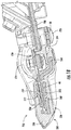
- FIGS 16-18 illustrate portions of cutter assembly 520, provided as part of header 700, in more detail.
- cutter assembly 520 comprises cutter bar 720, hold downs 724, fasteners 726, knife bar or sickle bar 730 and knife sections 732.
- Cutter bar 720 comprises an elongate bar coupled to frame 702 and supported along the front of header 700 and along the front of drapers 706 (shown in Figure 15 ).
- Cutter bar 720 knife guards holders 524 and knife guards 526.
- Hold downs 724 comprise structures that are mounted to cutter bar 720 and that face upper surfaces of knife sections 732 to hold down such knife section 732 during reciprocation such that knife sections 732 transversely pass through the knife channels 44 of knife guards 526.
- Fasteners 726 extends through both mounting apertures 34 of knife guard holder 524, through corresponding apertures and cutter bar 720 and through corresponding aligned apertures of hold down 724.
- both knife guard holders 524 and hold down 724 are mounted on opposite sides of cutter bar 720 by a single fastener or set of fastener 726.
- Knife bar or sickle bar 730 comprises an elongate structure to which knife sections 732 are mounted.
- Knife sections 732 comprise individual knives mounted to bar 730 along the length of bar 730. Knife section 732 passed through knife channels 44 in finger 42A of knife guard 526. Knife sections 732 have serrated edges that cooperate with portions of metal inserts 552 and 554 to cut the plants.
Landscapes
- Life Sciences & Earth Sciences (AREA)
- Environmental Sciences (AREA)
- Zoology (AREA)
- Knives (AREA)
Abstract
Description
- Cutter assemblies are utilized in a wide variety of equipment for cutting various plants and growing medium. For example, cutter assemblies are found in combine harvesters, choppers, haybines, sicklebars and other agricultural implements. Such cutter assemblies may include knife guards that guide sliding and reciprocating movement of a cutting knife.
-
- Fig. 1
- is a perspective view of an example cutter assembly, with portions schematically shown).
- Fig. 2
- is an exploded perspective view of another example cutter assembly.
- Fig. 3
- is a sectional view of the example cutter assembly of
Figure 2 . - Fig. 4
- is a sectional view of another example cutter assembly.
- Fig. 6
- is a fragmentary, partially exploded perspective view of another example cutter assembly.
- Fig. 7
- is a front perspective view of another example cutter assembly.
- Fig. 8
- is a perspective view of the cutter assembly of
Figure 7 with portions transparently shown. - Fig. 9
- is a bottom view of the cutter assembly of
Figure 7 . - Fig. 10
- is a bottom view of the cutter assembly of
Figure 7 with portions transparently shown. - Fig.11
- is an exploded perspective view of the example cutter assembly of
Figure 7 . - Fig. 12
- is a side view of a portion of the example cutter assembly of
Figure 7 with portions transparently shown. - Fig. 13
- is a sectional view of the example cutter assembly of
Figure 7 . - Fig. 14
- is a fragmentary sectional view of a portion of another example cutter assembly.
- Fig. 15
- is a front perspective view of an example harvester with an example harvester head.
- Fig. 16
- is a fragmentary front top perspective view of a portion of the harvester head of
Figure 15 . - Fig. 17
- is a front bottom perspective view of the portion of the harvester head of
Figure 16 . - Fig. 18
- is a sectional view of a portion of the harvester head of
Figure 15 . - Repair and replacement of knife guards is often difficult. Such repair or replacement may require complete disassembly of many components of the implement. For example, repair or replacement of a knife guard may frequently require the removal of bolts along with skid shoes. The removal of these components may require the use of tools. When such repair or replacement occurs in the field, the required tools may not be available or such parts, when removed, may become lost.
- Disclosed herein are various examples of cutter assemblies that facilitate simpler and less time-consuming repair or replacement of knife guards. The example cutter assemblies facilitate removal and separation of knife guards from the cutter assembly with minimal use of or no use of tools. The example cutter assemblies further facilitate removal and separation of knife guards from the cutter assembly with a minimal number of fasteners or no fasteners or components, reducing the likelihood that such removed fasteners or components may be lost in the field. The example cutter assemblies further allow existing agricultural and other implements to be modified for their use. The example cutter assemblies further provide for the use of less complex, lighter weight and less expensive knife guards.
- Disclosed herein is an example cutter assembly that may include a knife guard holder to be removably connected to a cutter bar, a knife guard an interface between the knife guard holder and the knife guard. The knife guard may have a knife channel to slidably guide a cutter knife. The interface extends between the knife guard holder and the knife guard to locate and releasably retain the knife guard with respect to the knife guard holder.
- Disclosed herein is an example knife guard that may comprise an integral unitary polymer body, a first metal plate and a second metal plate. The polymer body may comprise a bar, a plurality of pointed fingers forwardly projecting from the bar and a plurality of wedge-shaped projections projecting rearwardly from the bar. The plurality of wedge-shaped projections are to be received within a corresponding plurality of wedge-shaped cavities. At least one of the pointed fingers forms a knife channel. The first metal plate may continuously extend across and be secured to the plurality of pointed fingers with the first metal cutter plate forming a floor of the knife channel. The second metal plate may be secured to the at least one of the pointed fingers forming the knife channel, wherein the second metal plate forms a ceiling of the knife channel.
- Disclosed herein is an example method for assembling a cutter assembly. The method may comprise removably mounting a knife guard holder to a cutter bar, wherein the knife guard holder comprising one of wedges and wedge-shaped cavities. The method may further comprise mounting a knife guard to the knife guard holder by inserting the other of the wedges and the wedge-shaped cavities of the knife guard into said one of the wedges and wedge-shaped cavities of the knife guard holder.
-
Figure 1 is a perspective view of a portion of anexample cutter assembly 20 that facilitates the repair or replacement of a knife guard. Cutter assembly comprisesknife guard holder 24,knife guard 26 and interface 30 (schematically illustrated). Knifeguard holder 24 comprises a component that is configured to be removably coupled to a cutter bar, also sometimes referred to as a staff, and that is to further configured to be removably coupled toknife guard 26 byinterface 30. - For purposes of this disclosure, the phrase "configured to" denotes an actual state of configuration that fundamentally ties the stated function/use to the physical characteristics of the feature proceeding the phrase "configured to". For purposes of this disclosure, the term "releasably" or "removably" with respect to an attachment or coupling of two structures means that the two structures may be repeatedly connected and disconnected to and from one another without material damage to either of the two structures or their functioning.
- For purposes of this disclosure, the term "coupled" shall mean the joining of two members directly or indirectly to one another. Such joining may be stationary in nature or movable in nature. Such joining may be achieved with the two members or the two members and any additional intermediate members being integrally formed as a single unitary body with one another or with the two members or the two members and any additional intermediate member being attached to one another. Such joining may be permanent in nature or alternatively may be removable or releasable in nature.
- In the example illustrated,
knife guard holder 26 is configured to be directly coupled to a cutter bar. In one implementation,knife cardholder 26 is formed from steel, aluminum or iron.Knife guard holder 26 comprises a pair ofrings 32 havingfastening apertures 34 through which fasteners, such as bolts, may pass and be connected to the cutter bar. In other implementations,knife guard holder 26 may comprise other mechanisms for releasable mounting and securing ofknife guard holder 26 to a cutter bar or other frame structure of an agricultural implement. -
Knife guard 26, also sometimes referred to as a sickle guard, comprises a device removably mounted toknife guard holder 26 byinterface 30 and configured to guide sliding and reciprocating movement of a cutter or knife.Knife guard 26 comprisesbar 40 and a plurality of forwardly projecting, generally pointed,fingers noses 43. Fingers 42 project forwardly frombar 40 in a direction away fromholder 24. At least one of fingers 42 comprise a rearwardly facingknife channel 44 that slidably receives portions of a knife, namely, knife sections of the knife. Theknife channel 44 comprises both a bottom surface orfloor 46 and an opposite upper surface orceiling 48 defined by the finger 42. - In the example illustrated,
knife guard 26 comprises three fingers 42: a middle orcentral finger 42A that comprisesknife channel 44 and two lateral orside fingers knife guard 26 may have other arrangements of fingers 42. For example, in other implementations,knife guard 26 may alternatively comprise a pair of fingers 42 which each of fingers 42 having a configuration similar tofinger 42A. In yet other implementations,knife guard 26 may alternatively comprise a pair of fingers 42, with one of fingers 42 being configured similar tofinger 42A and with the other of the fingers 42 being configured similar tofinger 42C. In still other implementations,knife guard 26 may comprise more than three fingers 42, wherein the multiple fingers 42 have various combinations of fingers similar tofinger 42A and fingers similar tofingers - In one implementation,
knife guard 26 is formed from a metal material. For example, oneimplementation knife guard 26 is formed from a cast steel, aluminum, iron or various metal alloys. In yet another implementation,knife guard 26 is formed from a ceramic or polymer material. For example, in one implementation,knife guard 26 may be formed from a composite glass reinforced polymer. In some implementations,knife guard 20 formed from a ceramic or polymer, wherein those portions ofknife guard 26 that contact the knife are provided with a metal surface. As will be described hereafter, in some implementations,knife guard 26 may comprise a polymer outer body with metal plates that interface with the reciprocating knife. As will be described hereafter, in some implementations,knife guard 26 may comprise a polymer outer body with a metal insert or core at least partially encapsulated by the polymer outer body. -
Interface 30 comprises a mechanical interconnection betweenknife guard holder 24 andknife guard 26.Interface 30 locates and retainsknife guard 26 relative toknife guard holder 24.Interface 30 facilitates removable separation ofknife guard holder 24 andknife guard 26. In one implementation,interface 30 comprises cooperating portions of bothknife guard holder 24 andknife guard 26.Interface 30 facilitates a releasable connection ofknife controller 24 toknife guard 26 in a fashion so as to reduce or eliminate fasteners and so as to reduce or eliminate reliance upon tools for such disconnection.Interface 30 may enable quicker and easier separation ofknife guard 26 for repair and/or replacement. - In one implementation,
interface 30 comprises male and female connection portions associated with theknife guard holder 24 and theknife guard 26, wherein the male connection portion mates with the female connection portion to facilitate releasable connection ofknife guard holder 24 toknife guard 26. In one implementation, the interface comprises male and female connection portions that wedge within one another. For example, in one implementation,interface 30 comprises a tapering wedge-shaped projection and a tapering wedge-shaped cavity that receives the projection. The wedge-shaped rejection tapering wedge shaped cavity take primary and secondary loads during operation ofcutter assembly 20.
In some implementations, additional or alternative retaining mechanisms may be employed to secureknife guard 26 toknife guard holder 24. For example, in one implementation, the male connection portion may additionally comprise a catch or dovetail that resiliently snaps into a detent or that resiliently snaps behind an edge of the female connection portion. In one implementation,interface 30 may comprise a spring pin or quarter turn locking device to releasablysecure knife guard 26 toknife cardholder 24. In one implementation, theinterface 30 may additionally or alternatively utilize magnetic attraction to assist in retaining the connection ofknife guard 26 andknife guard holder 24. For example, one or both of the male connection portion and the female connection portion may include a magnetized material or magnet. One of the male connection portion and the female connection may include a magnetized material or magnet while the other of the male connection portion and the female connection portion comprises a ferrous material. In yet another implementation, theknife guard holder 24 andknife guard 26 may comprise aligned channels that removably receive a retention pin. -
Figure 2 is an exploded perspective view of a portion of anotherexample cutter assembly 120 comprisingknife guard holder 24,knife guard 26 and aspecific example interface 130.Interface 130 comprises tapering wedge-shapedprojections 132 and corresponding internally tapering wedge-shapedcavities 134. In the example illustrated,projections 132 andcavities 134 have frustro-conical shapes. In other implementations,projections 132 andcavities 134 may have other corresponding tapering wedge-shapes. For example,projections 132 andcavities 134 may alternatively have tapering polygonal cross-sectional shapes, such as a flat-top pyramid shape. Althoughprojections 132 are illustrated as being provided as part ofknife guard 26, projecting rearwardly frombar 40 whilecavities 134 are illustrated as being provided as part ofknife guard holder 24, projecting forwardly fromrings 32, in other implementations, this relationship may be reversed such thatprojections 132 extend forwardly fromrings 32 ofknife guard holder 24 whilecavities 134 are formed within or project rearwardly frombar 40. -
Figure 3 is a sectional view, throughfinger 42A, illustratinginterface 130 removably connectingknife guard 26 toknife guard holder 24. As shown byFigure 3 ,projections 132 are wedged intocavities 134, inhibiting relative movement therebetween but for movement ofknife guard 26 in a forward direction. As the forces imposed uponknife guard 26 during use tend to further moveknife guard 26 rearwardly, to the right in the illustrated figure,projections 132 are less likely to become accidentally dislodged fromcavities 134. -
Figure 3 further illustrates a variation ofknife guard 26, wherein the outer body ofknife guard 26 may be formed from a polymer material or a combination of materials that may be susceptible to abrasion wear from a reciprocating knife and wherein portions ofknife channel 44 that might otherwise contact and wear against knife are provided with alayer knife guard 26. For example, in one implementation, layers 141, 142 may comprise metal plates secured to the polymer outer body ofknife guard 26. In one implementation, such metal plates may be fastened to the remainder ofknife guard 26, may be bonded to the remainder ofknife guard 26 and/or may be mechanically locked to the remainder ofknife guard 26 such as where the remainder ofknife guard 26 is molded and encapsulates selected portions of the metal plates. In another implementation, layers 141, 142 may comprise a lamination or coating on the remainder ofknife guard 26. In such implementations, layers 141, 142 may provide sharp edges that cooperate with the knife to further facilitate cutting. -
Figure 4 is a flow diagram of anexample method 200 for assembling a cutter assembly.Method 200 facilitates separation of the knife guard from the remainder of an implement with minimal or no use of tools and with minimal or no use of fasteners. Althoughmethod 200 is described in the context of being carried out withinterface 130 betweenknife guard holder 24 andknife guard 26, it should be appreciative thatmethod 200 may be carried out with any of the knife guards and knife guard holders, and their respective interfaces, describing this disclosure or other interfaces having similar characteristics. It should further be appreciated thatmethod 200 may be reversed to facilitate removal and separation ofknife guard 26 from the remainder of an implement. - As indicated by
block 202,knife guard holder 24 is removably mounted to a cutter bar. In one implementation, fasteners are inserted throughfasting apertures 34 and connected to portions of the cutter bar.Knife guard holder 24 comprises one ofwedges 132 and wedge-shapedcavities 134. - As indicated by
block 204,knife guard 26 is mounted toknife guard holder 24 by inserting the other of the wedges and the wedge-shaped cavities of the knife guard into said one of the wedges and wedge-shaped cavities of the knife guard holder. In the example illustrated,wedges 132 ofknife guard 26 are inserted into wedge-shapedcavities 134 ofknife guard holder 24. -
Figure 5 is a sectional view of a portion of anexample cutter assembly 320, wherein the assembledknife guard holder 24 andknife guard 26 are removably connected to one another by yet anotherexample interface 330. Those components ofcutter assembly 320 which correspond to components ofcutter assembly 120 are numbered similarly. -
Interface 330 issimilar interface 130 described above in thatinterface 330 comprises tapering wedge-shapedcavities 134 in whichwedges 132 are wedged. In contrast to interface 130,projections 132 andcavities 134 are additionally lined or coated withlayers wedges 132 and the interior surfaces ofcavities 134. In another implementation, one or both oflayers projections 132 andcavities 134. - In one implementation, layers 332, 334 are formed from materials different than the adjacent materials of
projections 132 andcavity 134 so as to provide abrasion resistance, reducing abrasion. In another implementation,layer 322 and 334 are formed from materials different than the adjacent materials ofprojections 132 andcavity 134 so as to provide enhanced gripping, whereinlayers projections 132 andcavity 134. - In yet other implementations,
layer projections 132 andcavity 134 so as to provide magnetic attraction betweenprojections 132 andknife guard holder 24. For example, in one implementation, both oflayers layer layer wedges 132 may be entirely formed from a ferrous material whilecavity 134 comprises the magnet such thatlayer 332 may be omitted. In some implementations, at least portions ofcavity 134 may be entirely formed from a ferrous material whilewedges 132 comprise a magnet such thatlayer 334 may be omitted. In implementations wherelayer layer wedges 132 or the material ofknife guard holder 24 aboutcavity 134, covered by a thin layer of nonferrous or non-magnetic material. For example, in one implementation,holder 24 may be formed from a ferrous material, whereinwedges 132 completely surround and embed an internal magnet. -
Figure 6 illustrates a portion of anotherexample cutter assembly 420 comprisingknife guard holder 24,knife guard 26 and another example interface 430. Interface 430 utilizes a pair of aligned channels and a retention pin to releasably retaininsecure knife guard 26 toknife guard holder 24. Those components ofcutter assembly 420 which correspond to components ofcutter assembly 20 orcutter assembly 120 are numbered similarly. - Interface 430 comprises
extensions 432,cavities 434, andretention pin 436.Extensions 432 rearwardly project from bar 430 and form alignedchannels 438. In the example illustrated,extensions 432 have hook or claw-shaped ends that form the alignedchannels 438. In other implementations,extensions 432 may alternatively comprise bores, completely surrounded by the material ofextensions 432, wherein the bores have interiors forming the alignedchannels 438. -
Cavities 434 extend into portions ofknife guard holder 24 and correspond toextensions 432 so as to removably receiveextensions 432. Each ofcavities 434 compriseside openings 440 that are aligned withchannels 438 whenextensions 432 are fully inserted intocavities 434.Side openings 440 provide aligned passages throughknife guard holder 24 to facilitate insertion ofretention pin 436 through each ofside openings 440 and throughchannels 438 to inhibitwithdrawal extensions 432 fromcavities 434. In one implementation,extensions 432 andcavities 434 have cross-sections that do not taper. In another implementation,extensions 432 andcavities 434 have tapering cross-sections, further facilitating securement ofextensions 432 withincavities 434 by the wedging ofextensions 432 withincavities 434. -
Retention pin 436 comprises an elongate shaft or pin configured to slidably pass throughopening 440 andchannels 438, extending across each ofextensions 432 ofknife guard 26. In one implementation,retention pin 436 comprises a cotter pin. In yet another implementation,retention pin 436 comprises a threaded bolt for use with an associated threaded nut. Removal ofretention pin 436 allowsextensions 432 to be manually pulled and withdrawn fromcavities 434, facilitating separation ofknife guard 26 fromknife guard holder 24 and the remainder of the implement. -
Figures 7-13 illustrate a portion of anotherexample cutter assembly 520 comprisingknife guard holder 524 andknife guard 526 releasably connected to one another by aninterface 530.Knife guard holder 524 is similar toknife guard holder 24 described above except thatknife guard holder 524 comprises portions ofinterface 530. -
Knife guard 526 is similar toknife guard 26 in thatknife guard 526 comprises fingers 42 formerly projecting from abar 40, wherein at least one of the fingers 42 comprises aknife channel 44. As shown byFigure 11 , unlikeknife guard 26,knife guard 526 is specifically illustrated as comprising anouter polymer body 550 and metal inserts 552, 554.Figure 11 illustrates metal inserts 552, 554 exploded away from and separated from theouter polymer body 550.Figure 8 ,10 and12 transparently illustrate portions of outerpolymeric body 552 illustrate the interrelationship betweenbody 550 and metal inserts 552, 554.Figure 13 is a sectional view throughfinger 42A. - Outer
polymeric body 550 comprise a single integral unitary body form from a polymer or mixture the different polymers. In one implementation,outer polymerbody 550 is formed from a material such as a composite glass reinforced polymer, such as a glass reinforced polymer. The polymermaterial forming body 550 reduces the weight ofcutter assembly 520 as well as its cost. - Outer
polymeric body 550 forms bar 40 and each of fingers 42 described above. As shown byFigures 11 and12 ,outer polymer body 550 extends about opposite sides of portions of metal inserts 552, 554 and/or within apertures within metal inserts 552, 554 to retainmetal inserts body 550 in at least one direction. As shown byFigure 13 , in one implementation,outer polymer body 550 is molded about metal inserts 552, 554 so as to at least partially encapsulate multiple pairs of opposite sides ofmetal insert inserts polymer body 550 may comprise projections that make within corresponding apertures ininserts metal insert body 550. -
Metal insert 552 comprises a metallic structure formed from a metal such as 1070 steel or various alloys.Metal insert 552 comprises ametal plates extensions 562.Metal plates fingers Metal plate 560A forms the lower surface orfloor 46 ofknife channel 44. Metal plates 560 further provide sharp metal edges, such asedges - As indicated above, in the example illustrated, metal plates 560 comprise
apertures 566 through which the polymer material ofbody 550 may extend and be captured. As illustrated byFigure 13 , each of metal plates 560 comprises at least one downwardly extendingtang 568 which is completely encapsulated and surrounded by the polymer material ofbody 550. Such encapsulation further reliably secures and retainsinsert 552 in place with respect tobody 550. In other implementations,tangs 568 and/orapertures 566 may be omitted. -
Extensions 562 extend rearwardly from plates 560 and are completely encapsulated bypolymer body 550. In the example illustrated,extensions 562 are completely encapsulated by those portions ofpolymer body 550 forming part ofinterface 530.Extensions 562 different and rigidify those portions ofpolymer body 550 forming part ofinterface 530. In the example illustrated,extensions 562 are integrally formed as a single unitary body with plates 560. In one implementation,extensions 562 and plates 560 are formed from a stamped and deformed sheet of metal. In other implementations,extensions 562 and plates 560 are formed through casting or molding. -
Metal insert 554 comprises a metal plate secured tocentral finger 42A aboveknife channel 44.Metal insert 554 forms an upper surface orceiling 48 ofknife channel 44 and provide services against which the upper surface of the received knife may bear against. Similar tometal plate 560A,metal insert 552 provides sharp wear resistant metal edges, such as edge 568 (shown inFigure 12 ), that interact with such knives to facilitate cutting of the plants. - In the example illustrated,
metal insert 554 is a separate piece frommetal insert 552. Similar tometal insert 552,metal insert 554 comprisesapertures 570 through which the polymer material ofbody 550 may extend and be captured. As illustrated byFigure 13 ,metal insert 552 may further comprise at least one upwardly extendingtang 572 which is completely encapsulated and surrounded by the polymer material ofbody 550. Such encapsulation further reliably secures and retainsinsert 554 in place with respect tobody 550. In other implementations,tang 572 and/orapertures 570 may be omitted. In some implementations,metal insert 554 may be bonded, snapped or fastened tobody 550. In some implementations, in lieu of being a separate component frominsert 552, insert 554 may be integrally formed as part of a single unitary body withinsert 552, having a horizontal U shape and extending rearwardly from a front edge ofmetal plate 560A. - Interface 530 releasably connects
knife guard holder 24 andknife guard 526. In the example illustrated,interface 530 compriseswedges 532, wedge-shapedcavities 534 and catches 536.Wedges 532 extend rearwardly frombar 40 and rearwardly taper, having a gradually rearwardly decreasing cross-sectional area. As shown byFigure 13 , in the example illustrated,wedges 532 are integrally formed as part of a single unitary body withbar 40 and the remainder ofpolymer body 550. -
Wedges 532 surround portions ofextensions 562 ofmetal insert 552. As shown byFigure 13 ,extensions 562, along withwedges 532 are received within wedge-shapedcavities 534. As a result, as shown byFigure 13 , thejunction 576 ofprojections 532 andcavities 534 is further stiffened and strengthened by theinternal extension 562. In the example illustrated, eachwedge 534 has a tapering flat pyramid or tapering trapezoidal cross section shape. In other implementations, eachwedge 534 may have a conical or frustro-conical shape similar toprojections 132 described above. - Wedge-shaped
cavities 534 extend forwardly from a remainder ofknife guard holder 524. Wedge-shapedcavities 534 are similar to wedge-shapedcavities 134 described above except that wedge-shapedcavities 534 have internally tapering trapezoidal cross sectional shapes. As indicated above, depending upon the shape ofwedges 532, wedge-shapedcavity 534 may have other tapering internal cavity shapes. - Catch 534 comprise a hook or other projection extending from
wedge 532 so as to resiliently snap into a corresponding detent or void within or at the end of the corresponding wedge-shapedcavity 534. In the example illustrated, eachcatch 534 comprises a dovetail. As shown byFigures 12 and 13 , catch 536 contacts and engages anexternal edge 576 at the end ofcavity 534 whenwedges 532 have been sufficiently and fully inserted into (and through)cavities 534. In such an implementation, catches 536 not only retainwedges 532 withincavities 534 to prevent accidental withdrawal, but also provide a tactile indication of whenwedges 532 have been sufficiently inserted intocavities 534. Withdrawal ofwedges 532 fromcavities 534 may be achieved by resiliently flexingcatches 536 upwardly toclear edge 576. -
Figure 14 is a sectional view of a portion of anotherexample cutter assembly 620.Cutter assembly 620 is similar tocutter assembly 520 described above except thatcutter assembly 620 comprises additional retention features for retainingwedges 532 withincavities 534. In the example illustrated, cut orsemi 620 further compriseslayer layer wedges 532 withincavities 534. In the example illustrated,projections 532 and portions ofknife guard holder 524 additionally comprise alignedchannels 680 that receive a retention pin 682 (shown in broken lines) to further assist in retainingwedges 532 withincavities 534. In some implementations, one or more of such features,layer 322, 334 orchannel 680 and pin 682 may be omitted. -
Figures 15-18 illustratecutter assembly 520 as part of anexample header 700 for a combine harvester 701.Header 700 is shown as a draper header. It should be appreciated thatcutter assembly 520 may likewise be utilized in other harvester headers, such as auger platforms and rigid draper platforms. As indicated above, in some implementations,cutter assembly 520 may be utilized in other agriculture implement such as sickle bars and haybines. - As shown by
Figure 15 , theexample header 700 generally comprisesframe 702,cutter assembly 520, gatheringreels 704,drapers central draper 707 and feeddrum 708.Frame 702 forms the exterior ofheader 700 and supports remaining components ofheader 700.Frame 702 is configured to be releasably mounted to a combine harvester 701. - Gathering
reels 704 gathering direct the crop towardscutter assembly 520.Cutter assembly 520 cuts and are severs the crop or plant from soil. Drapers 706 comprise carpets, platforms or belts which are transversely driven so as to carry the severed plants or crops tocentral draper 707.Draper 706R carries the severed crops in the direction indicated byarrow 710 ordraper 706L carrier severed crops in the direction indicated by arrow 711.Central draper 707 conveys the severed crop material to feeddrum 708.Feed drum 708 is rotatably driven so as to move the severed crop material rearwardly into afeeder house 709 of harvester 701 for threshing. -
Figures 16-18 illustrate portions ofcutter assembly 520, provided as part ofheader 700, in more detail. As shown by such figures, in addition toknife guard holder 524, andknife guard 526, as releasably connected byinterface 530,cutter assembly 520 comprisescutter bar 720, holddowns 724,fasteners 726, knife bar orsickle bar 730 andknife sections 732.Cutter bar 720 comprises an elongate bar coupled toframe 702 and supported along the front ofheader 700 and along the front of drapers 706 (shown inFigure 15 ).Cutter bar 720knife guards holders 524 and knife guards 526. - Hold
downs 724 comprise structures that are mounted tocutter bar 720 and that face upper surfaces ofknife sections 732 to hold downsuch knife section 732 during reciprocation such thatknife sections 732 transversely pass through theknife channels 44 of knife guards 526.Fasteners 726 extends through both mountingapertures 34 ofknife guard holder 524, through corresponding apertures andcutter bar 720 and through corresponding aligned apertures of hold down 724. As a result, bothknife guard holders 524 and hold down 724 are mounted on opposite sides ofcutter bar 720 by a single fastener or set offastener 726. Knife bar orsickle bar 730 comprises an elongate structure to whichknife sections 732 are mounted.Bar 730 is connected to a head (not shown) which is connected to a reciprocating drive left for not shown) that reciprocatesbar 730 along the front ofheader 700.Knife sections 732 comprise individual knives mounted to bar 730 along the length ofbar 730.Knife section 732 passed throughknife channels 44 infinger 42A ofknife guard 526.Knife sections 732 have serrated edges that cooperate with portions of metal inserts 552 and 554 to cut the plants. - Although the present disclosure has been described with reference to example implementations, workers skilled in the art will recognize that changes may be made in form and detail without departing from the spirit and scope of the claimed subject matter. For example, although different example implementations may have been described as including one or more features providing one or more benefits, it is contemplated that the described features may be interchanged with one another or alternatively be combined with one another in the described example implementations or in other alternative implementations. Because the technology of the present disclosure is relatively complex, not all changes in the technology are foreseeable. The present disclosure described with reference to the example implementations and set forth in the following claims is manifestly intended to be as broad as possible. For example, unless specifically otherwise noted, the claims reciting a single particular element also encompass a plurality of such particular elements. The terms "first", "second", "third" and so on in the claims merely distinguish different elements and, unless otherwise stated, are not to be specifically associated with a particular order or particular numbering of elements in the disclosure.
Claims (20)
- A cutter assembly comprising:a knife guard holder to be removably connected to a cutter bar;a knife guard having a knife channel to slidably guide a cutter knife; andan interface between the knife guard holder and the knife guard to locate and releasably retain the knife guard with respect to the knife guard holder.
- The cutter assembly claim 1, wherein the interface comprises:a wedge extending from one of the knife guard holder in the knife guard; anda wedge shaped cavity extending from the other of the knife guard holder and the knife guard, the wedge-shaped cavity releasably receiving the wedge to locate and releasably retain the knife guard with respect to the knife guard holder.
- The cutter assembly of claim 1, wherein interface comprises:a wedge extending from one of the knife guard holder and the knife guard; anda wedge shaped cavity extending from the other of the knife guard holder and the knife guard, the wedge-shaped cavity releasably receiving the wedge to locate and releasably retain the knife guard with respect to the knife guard holder;a detent along one of the wedge and the wedge-shaped cavity; anda catch projecting from the other of the wedge and the wedge-shaped cavity, the catch being received within the detent.
- The cutter assembly of claim 1, wherein interface comprises:a wedge extending from one of the knife guard holder and the knife guard;a wedge shaped cavity extending from the other of the knife guard holder and the knife guard, the wedge-shaped cavity releasably receiving the wedge to locate and releasably retain the knife guard with respect to the knife guard holder; anda magnetic material proximate one of the wedge in the wedge-shaped cavity, wherein the other of the wedge and the wedge-shaped cavity comprise a ferous material, the first material and the magnetic material being magnetically attracted to one another to retain the wedge within the wedge-shaped cavity.
- The cutter assembly of claim 1, wherein the interface comprises:a wedge extending from one of the knife guard holder and the knife guard;a wedge shaped cavity extending from the other of the knife guard holder and the knife guard, the wedge-shaped cavity releasably receiving the wedge to locate and releasably retain the knife guard with respect to the knife guard holder;a magnetic material proximate one of the wedge in the wedge-shaped cavity, wherein the other of the wedge and the wedge-shaped cavity comprise a ferous material, the first material and the magnetic material being magnetically attracted to one another to retain the wedge within the wedge-shaped cavity;a detent coupled to one of the knife guard holder and the knife guard; anda catch coupled to the other of the knife guard holder and the knife guard, the catch being received within the detent.
- The cutter assembly of claim 1, wherein interface comprises:a wedge extending from one of the knife guard holder and the knife guard;a wedge shaped cavity extending from the other of the knife guard holder and the knife guard, the wedge-shaped cavity releasably receiving the wedge to locate and releasably retain the knife guard with respect to the knife guard holder; anda retention pin extending through the wedge-shaped cavity and the wedge within the wedge-shaped cavity.
- The cutter assembly of claim 1, wherein interface comprises:a wedge extending from one of the knife guard holder and the knife guard;a wedge shaped cavity extending from the other of the knife guard holder and the knife guard, the wedge-shaped cavity releasably receiving the wedge to locate and releasably retain the knife guard with respect to the knife guard holder;a magnetic material proximate one of the wedge in the wedge-shaped cavity, wherein the other of the wedge and the wedge-shaped cavity comprise a ferous material, the first material and the magnetic material being magnetically attracted to one another to retain the wedge within the wedge-shaped cavity;a detent coupled to one of the knife guard holder and the knife guard;a catch coupled to the other of the knife guard holder and the knife guard, the catch being received within the detent; anda retention pin extending through the wedge-shaped cavity and the wedge within the wedge-shaped cavity.
- The cutter assembly of claim 1, wherein the knife guard comprises:a metal cutter surface along a floor of the knife channel; anda polymer outer body supporting the metal cutter surface and forming an upper surface of the knife channel.
- The cutter assembly of claim 1, wherein the knife guard comprises:a metal insert forming a floor of the knife channel, the metal insert comprising apertures; anda polymer outer body projecting through the apertures and underlying the metal insert.
- The cutter assembly of claim 1, wherein the interface comprise:a plurality of frustro-conical projections extending from one of the knife guard holder and the knife guard; anda plurality of frustrated-conical cavities extending into the other of the knife guard holder andthe knife guard and corresponding to the plurality of frustrated-conical projections.
- The cutter assembly of claim 1, wherein the knife guard holder comprises three wedge-shaped cavities and wherein the knife guard comprises:a polymer body comprising:first and second outer fingers;a central finger between the first and second outer fingers and having the knife channel; andthree wedge-shaped projections responding to the three wedge-shaped cavities and wedged into the three wedge-shaped cavities;a first metal cutter plate continuously extending across the first and second outer fingers andthe central finger, the metal cutter plate forming an upper surface of the first and second outer fingers and a floor of the knife channel; anda second metal cutter plate supported by the central finger and forming a ceiling of the knife channel.
- The cutter assembly of claim 11, wherein the first metal cutter plate comprises extensions encapsulated within each of the first and second outer fingers in the central finger, the extensions being received within each of the three wedge-shaped cavities of the knife guard holder.
- The cutter assembly of claim 11, wherein the knife channel of the knife guard extends above each of the three-wedge-shaped apertures.
- The cutter assembly of claim 11, wherein each of the three wedge-shaped cavities face in a first direction and wherein the knife guard holder comprises at least one second aperture extending in a second direction perpendicular to the first direction, the at least one second aperture to receive a fastener for removably mounting the knife guard holder to the cutter bar.
- The cutter assembly of claim 1, wherein the knife guard holder comprises three wedge-shaped cavities and wherein the knife guard comprises:a polymer body comprising:first and second outer fingers;a central finger between the first and second outer fingers and having the knife channel; andthree wedge-shaped projections responding to the three wedge-shaped cavities and wedged into the three wedge-shaped cavities; anda dovetail projecting from an end of at least one of the three wedge-shaped projections, the dovetail projecting beyond a corresponding one of the three wedge-shaped cavities to catch on an exterior of the corresponding one of the three wedge-shaped cavities; anda first metal cutter plate continuously extending across the first and second outer fingers andthe central finger, the metal cutter plate forming an upper surface of the first and second outer fingers and a floor of the knife channel.
- The cutter assembly of claim 1 further comprising:a cutter bar;a knife hold down; anda fastener extending through the knife hold down, through the cutter bar and through the knife guard holder.
- A method for assembling a cutter assembly, the method comprising:removably mounting a knife guard holder to a cutter bar, the knife guard holder comprising one of wedges and wedge-shaped cavities; andmounting a knife guard to the knife guard holder by inserting the other of the wedges and the wedge-shaped cavities of the knife guard into said one of the wedges and wedge-shaped cavities of the knife guard holder.
- A knife guard for a cutter assembly, the knife guard comprising:an integral unitary polymer body comprising:a bar;a plurality of pointed fingers forwardly projecting from the bar, at least one of the pointed fingers forming a knife channel; anda plurality of wedge-shaped projections projecting rearwardly from the bar to be received within a corresponding plurality of wedge-shaped cavities; anda first metal metal plate continuously extending across and secured to the plurality of pointed fingers, the first metal cutter plate forming a floor of the knife channel; anda second metal plate secured to the at least one of the pointed fingers forming the knife channel, the second metal plate forming a ceiling of the knife channel.
- The knife guard of claim 18, wherein at least one of the plurality of wedge-shaped projections comprises a dovetail to catch on an exterior of the corresponding one of the plurality of wedge-shaped cavities when the plurality of wedge-shaped projections are received within the plurality of wedge-shaped cavities.
- The knife guard of claim 18, wherein the first metal plate comprises extensions completely encapsulated by and extending within the plurality of wedge-shaped projections.
Applications Claiming Priority (1)
| Application Number | Priority Date | Filing Date | Title |
|---|---|---|---|
| US15/294,294 US10973170B2 (en) | 2016-10-14 | 2016-10-14 | Cutter assembly with knife guard and knife guard holder |
Publications (2)
| Publication Number | Publication Date |
|---|---|
| EP3308620A1 true EP3308620A1 (en) | 2018-04-18 |
| EP3308620B1 EP3308620B1 (en) | 2021-05-26 |
Family
ID=60083861
Family Applications (1)
| Application Number | Title | Priority Date | Filing Date |
|---|---|---|---|
| EP17196337.4A Active EP3308620B1 (en) | 2016-10-14 | 2017-10-13 | Cutter assembly with knife guard and knife guard holder |
Country Status (4)
| Country | Link |
|---|---|
| US (1) | US10973170B2 (en) |
| EP (1) | EP3308620B1 (en) |
| CN (1) | CN107950170B (en) |
| BR (1) | BR102017019644A2 (en) |
Cited By (2)
| Publication number | Priority date | Publication date | Assignee | Title |
|---|---|---|---|---|
| WO2019081728A3 (en) * | 2017-10-27 | 2019-07-11 | ESM Ennepetaler Schneid- u. Mähtechnik GmbH & Co. KG | Header system |
| WO2026057297A1 (en) * | 2024-09-11 | 2026-03-19 | Betek Gmbh & Co. Kg | Cutting tool |
Families Citing this family (4)
| Publication number | Priority date | Publication date | Assignee | Title |
|---|---|---|---|---|
| GB201714192D0 (en) * | 2017-09-05 | 2017-10-18 | Agco Do Brazil Comercio E Ind Ltda | Sickle guard counterknife insert |
| SE1950655A1 (en) * | 2019-06-04 | 2020-12-05 | Husqvarna Ab | Electrically powered, universal accessory drive |
| DE102019129219A1 (en) * | 2019-10-29 | 2021-04-29 | SMF - Holding GmbH | Method of making a knife blade and knife blade |
| CN111788956B (en) * | 2020-08-11 | 2021-09-07 | 浙江锐木园林机械有限公司 | Lithium electricity gardens pruner |
Citations (3)
| Publication number | Priority date | Publication date | Assignee | Title |
|---|---|---|---|---|
| US936063A (en) * | 1908-11-24 | 1909-10-05 | Joseph Weigel | Finger bar and guard. |
| US1374973A (en) * | 1920-05-01 | 1921-04-19 | Witte Theodore | Guard-finger and finger-bar |
| US20150082764A1 (en) * | 2013-09-26 | 2015-03-26 | Kondex Corporation | Laser hardened knife guard |
Family Cites Families (23)
| Publication number | Priority date | Publication date | Assignee | Title |
|---|---|---|---|---|
| US10581A (en) * | 1854-02-28 | Improvement in harvesters | ||
| US1890997A (en) * | 1932-05-25 | 1932-12-13 | Finkl & Sons Co | Forged dipper tooth |
| US2148186A (en) | 1938-02-25 | 1939-02-21 | Jacob J Buck | Finger guard |
| US2761269A (en) * | 1954-11-26 | 1956-09-04 | Case Co J I | Sickle bar construction |
| SE450504B (en) * | 1983-07-26 | 1987-06-29 | Bofors Wear Parts Ab | WRADING SYSTEM FOR EQUIPMENT TOOLS |
| US4575998A (en) | 1984-03-26 | 1986-03-18 | Brooks Donald G | Harvester comb fingers |
| US5123237A (en) * | 1991-02-15 | 1992-06-23 | Lavelle Industries, Inc. | Sickle blade guide |
| US6085510A (en) * | 1999-05-12 | 2000-07-11 | Mcdonnell; Steve C. | Sickel guard air system |
| CN2448067Y (en) * | 2000-09-07 | 2001-09-19 | 佳木斯铸造厂 | Guard finger assembly |
| CN2647109Y (en) * | 2003-09-15 | 2004-10-13 | 李贵频 | Antitheft button for carry-on articles |
| US20070193243A1 (en) | 2006-02-10 | 2007-08-23 | Schmidt James R | Combine Harvester Draper Header Having Flexible Cutterbar |
| US7870713B2 (en) * | 2008-02-11 | 2011-01-18 | Cnh America Llc | Sickle guard with integral streamlined air discharge system for blowing plant material toward a header of an agricultural plant cutting machine |
| CN201210802Y (en) * | 2008-03-21 | 2009-03-25 | 开封市海德机械有限公司 | Vertical combination tool of harvester |
| US8151547B2 (en) | 2009-10-02 | 2012-04-10 | Cnh America Llc | Blade assembly removal from a header of a plant cutting machine |
| DE102010011941A1 (en) * | 2010-03-18 | 2011-09-22 | Gebr. Schumacher Gerätebaugesellschaft mbH | mowing finger arrangement |
| CN102040116A (en) * | 2010-12-25 | 2011-05-04 | 唐杰宇 | Mini-type gummed paper tape cut-off device |
| CN102128266B (en) * | 2011-03-18 | 2013-11-13 | 华南理工大学 | Mechanical swivel joint seal device |
| US20120255339A1 (en) | 2011-04-06 | 2012-10-11 | Moxlow David M | Method of making a forged sickle guard |
| CN202033977U (en) * | 2011-05-06 | 2011-11-09 | 浙江威谷光电科技有限公司 | Modular LED display screen box |
| US9648804B2 (en) | 2011-05-27 | 2017-05-16 | Cnh Industrial America Llc | Knife arm assembly for a sickle |
| WO2012166738A1 (en) | 2011-05-27 | 2012-12-06 | Cnh America Llc | Easily serviceable and removable self-adjudting knife arm and head assembly for a sickle |
| CN104696651A (en) * | 2014-12-03 | 2015-06-10 | 浙江超润润滑元件有限公司 | Fast pipe joint insertion structure |
| CN205105632U (en) * | 2015-11-18 | 2016-03-30 | 温岭市创嘉信息科技有限公司 | Modular lawnmower blade subassembly |
-
2016
- 2016-10-14 US US15/294,294 patent/US10973170B2/en active Active
-
2017
- 2017-09-14 CN CN201710826263.1A patent/CN107950170B/en active Active
- 2017-09-14 BR BR102017019644-5A patent/BR102017019644A2/en not_active Application Discontinuation
- 2017-10-13 EP EP17196337.4A patent/EP3308620B1/en active Active
Patent Citations (3)
| Publication number | Priority date | Publication date | Assignee | Title |
|---|---|---|---|---|
| US936063A (en) * | 1908-11-24 | 1909-10-05 | Joseph Weigel | Finger bar and guard. |
| US1374973A (en) * | 1920-05-01 | 1921-04-19 | Witte Theodore | Guard-finger and finger-bar |
| US20150082764A1 (en) * | 2013-09-26 | 2015-03-26 | Kondex Corporation | Laser hardened knife guard |
Cited By (2)
| Publication number | Priority date | Publication date | Assignee | Title |
|---|---|---|---|---|
| WO2019081728A3 (en) * | 2017-10-27 | 2019-07-11 | ESM Ennepetaler Schneid- u. Mähtechnik GmbH & Co. KG | Header system |
| WO2026057297A1 (en) * | 2024-09-11 | 2026-03-19 | Betek Gmbh & Co. Kg | Cutting tool |
Also Published As
| Publication number | Publication date |
|---|---|
| CN107950170B (en) | 2022-07-19 |
| US10973170B2 (en) | 2021-04-13 |
| CN107950170A (en) | 2018-04-24 |
| US20180103581A1 (en) | 2018-04-19 |
| EP3308620B1 (en) | 2021-05-26 |
| BR102017019644A2 (en) | 2018-05-02 |
Similar Documents
| Publication | Publication Date | Title |
|---|---|---|
| EP3308620B1 (en) | Cutter assembly with knife guard and knife guard holder | |
| US10920928B2 (en) | Adjustable carrier assembly for a harness | |
| CA2242213C (en) | String trimmer with fixed string head | |
| EP2568797B1 (en) | Modular floor assembly for a combine header | |
| US4519192A (en) | Hold-down sickle guard | |
| EP2939516B1 (en) | Spring plate configured to overlap with asymmetric/eccentric quick change knife nut for proper assembly | |
| EP3333997A1 (en) | Protective bundle routing grommet for wide range panel thicknesses | |
| US8833048B2 (en) | Harvesting header bat with adjustably spaced quick release fingers | |
| US11425859B2 (en) | Header cutting system with knife guards | |
| EP2957165B1 (en) | Crop stripper band | |
| JP7504107B2 (en) | Wear assemblies for earthmoving equipment | |
| EP3381267A1 (en) | Slat insert for noise/wear attenuation in a feederhouse conveyor | |
| US413116A (en) | Guard-finger | |
| EP2314144A1 (en) | Reduced-weight plant-cutting assembly for a header | |
| US10920851B1 (en) | Zipper assembly for a draper belt | |
| EP0700632A1 (en) | A cutting section for a cutting machine such as a mower or hedge trimmer | |
| EP3141105B1 (en) | Lockout fastener for a gathering chain assembly of an agricultural harvester row unit | |
| US11156264B2 (en) | Diagonal zipper assembly for a draper belt | |
| EP3405064A1 (en) | Improved zipper slider system | |
| US345439A (en) | James mcdermott | |
| US508114A (en) | murphy | |
| US20080155884A1 (en) | Fishing Lure Apparatus and Method | |
| US572402A (en) | Antifriction-clip for reapers and mowers | |
| JPH0729809Y2 (en) | Weeding guide for reaper | |
| US20150150190A1 (en) | Overlapping sickle section for a knife assembly |
Legal Events
| Date | Code | Title | Description |
|---|---|---|---|
| PUAI | Public reference made under article 153(3) epc to a published international application that has entered the european phase |
Free format text: ORIGINAL CODE: 0009012 |
|
| STAA | Information on the status of an ep patent application or granted ep patent |
Free format text: STATUS: THE APPLICATION HAS BEEN PUBLISHED |
|
| AK | Designated contracting states |
Kind code of ref document: A1 Designated state(s): AL AT BE BG CH CY CZ DE DK EE ES FI FR GB GR HR HU IE IS IT LI LT LU LV MC MK MT NL NO PL PT RO RS SE SI SK SM TR |
|
| AX | Request for extension of the european patent |
Extension state: BA ME |
|
| STAA | Information on the status of an ep patent application or granted ep patent |
Free format text: STATUS: REQUEST FOR EXAMINATION WAS MADE |
|
| 17P | Request for examination filed |
Effective date: 20181018 |
|
| RBV | Designated contracting states (corrected) |
Designated state(s): AL AT BE BG CH CY CZ DE DK EE ES FI FR GB GR HR HU IE IS IT LI LT LU LV MC MK MT NL NO PL PT RO RS SE SI SK SM TR |
|
| STAA | Information on the status of an ep patent application or granted ep patent |
Free format text: STATUS: EXAMINATION IS IN PROGRESS |
|
| 17Q | First examination report despatched |
Effective date: 20200708 |
|
| GRAP | Despatch of communication of intention to grant a patent |
Free format text: ORIGINAL CODE: EPIDOSNIGR1 |
|
| STAA | Information on the status of an ep patent application or granted ep patent |
Free format text: STATUS: GRANT OF PATENT IS INTENDED |
|
| INTG | Intention to grant announced |
Effective date: 20210104 |
|
| INTG | Intention to grant announced |
Effective date: 20210113 |
|
| GRAS | Grant fee paid |
Free format text: ORIGINAL CODE: EPIDOSNIGR3 |
|
| GRAA | (expected) grant |
Free format text: ORIGINAL CODE: 0009210 |
|
| STAA | Information on the status of an ep patent application or granted ep patent |
Free format text: STATUS: THE PATENT HAS BEEN GRANTED |
|
| AK | Designated contracting states |
Kind code of ref document: B1 Designated state(s): AL AT BE BG CH CY CZ DE DK EE ES FI FR GB GR HR HU IE IS IT LI LT LU LV MC MK MT NL NO PL PT RO RS SE SI SK SM TR |
|
| REG | Reference to a national code |
Ref country code: GB Ref legal event code: FG4D |
|
| REG | Reference to a national code |
Ref country code: CH Ref legal event code: EP |
|
| REG | Reference to a national code |
Ref country code: AT Ref legal event code: REF Ref document number: 1395280 Country of ref document: AT Kind code of ref document: T Effective date: 20210615 |
|
| REG | Reference to a national code |
Ref country code: DE Ref legal event code: R096 Ref document number: 602017039173 Country of ref document: DE |
|
| REG | Reference to a national code |
Ref country code: IE Ref legal event code: FG4D |
|
| REG | Reference to a national code |
Ref country code: LT Ref legal event code: MG9D |
|
| REG | Reference to a national code |
Ref country code: AT Ref legal event code: MK05 Ref document number: 1395280 Country of ref document: AT Kind code of ref document: T Effective date: 20210526 |
|
| PG25 | Lapsed in a contracting state [announced via postgrant information from national office to epo] |
Ref country code: HR Free format text: LAPSE BECAUSE OF FAILURE TO SUBMIT A TRANSLATION OF THE DESCRIPTION OR TO PAY THE FEE WITHIN THE PRESCRIBED TIME-LIMIT Effective date: 20210526 Ref country code: AT Free format text: LAPSE BECAUSE OF FAILURE TO SUBMIT A TRANSLATION OF THE DESCRIPTION OR TO PAY THE FEE WITHIN THE PRESCRIBED TIME-LIMIT Effective date: 20210526 Ref country code: BG Free format text: LAPSE BECAUSE OF FAILURE TO SUBMIT A TRANSLATION OF THE DESCRIPTION OR TO PAY THE FEE WITHIN THE PRESCRIBED TIME-LIMIT Effective date: 20210826 Ref country code: FI Free format text: LAPSE BECAUSE OF FAILURE TO SUBMIT A TRANSLATION OF THE DESCRIPTION OR TO PAY THE FEE WITHIN THE PRESCRIBED TIME-LIMIT Effective date: 20210526 Ref country code: LT Free format text: LAPSE BECAUSE OF FAILURE TO SUBMIT A TRANSLATION OF THE DESCRIPTION OR TO PAY THE FEE WITHIN THE PRESCRIBED TIME-LIMIT Effective date: 20210526 |
|
| REG | Reference to a national code |
Ref country code: NL Ref legal event code: MP Effective date: 20210526 |
|
| PG25 | Lapsed in a contracting state [announced via postgrant information from national office to epo] |
Ref country code: IS Free format text: LAPSE BECAUSE OF FAILURE TO SUBMIT A TRANSLATION OF THE DESCRIPTION OR TO PAY THE FEE WITHIN THE PRESCRIBED TIME-LIMIT Effective date: 20210926 Ref country code: GR Free format text: LAPSE BECAUSE OF FAILURE TO SUBMIT A TRANSLATION OF THE DESCRIPTION OR TO PAY THE FEE WITHIN THE PRESCRIBED TIME-LIMIT Effective date: 20210827 Ref country code: LV Free format text: LAPSE BECAUSE OF FAILURE TO SUBMIT A TRANSLATION OF THE DESCRIPTION OR TO PAY THE FEE WITHIN THE PRESCRIBED TIME-LIMIT Effective date: 20210526 Ref country code: RS Free format text: LAPSE BECAUSE OF FAILURE TO SUBMIT A TRANSLATION OF THE DESCRIPTION OR TO PAY THE FEE WITHIN THE PRESCRIBED TIME-LIMIT Effective date: 20210526 Ref country code: SE Free format text: LAPSE BECAUSE OF FAILURE TO SUBMIT A TRANSLATION OF THE DESCRIPTION OR TO PAY THE FEE WITHIN THE PRESCRIBED TIME-LIMIT Effective date: 20210526 Ref country code: NO Free format text: LAPSE BECAUSE OF FAILURE TO SUBMIT A TRANSLATION OF THE DESCRIPTION OR TO PAY THE FEE WITHIN THE PRESCRIBED TIME-LIMIT Effective date: 20210826 Ref country code: PT Free format text: LAPSE BECAUSE OF FAILURE TO SUBMIT A TRANSLATION OF THE DESCRIPTION OR TO PAY THE FEE WITHIN THE PRESCRIBED TIME-LIMIT Effective date: 20210927 Ref country code: PL Free format text: LAPSE BECAUSE OF FAILURE TO SUBMIT A TRANSLATION OF THE DESCRIPTION OR TO PAY THE FEE WITHIN THE PRESCRIBED TIME-LIMIT Effective date: 20210526 |
|
| PG25 | Lapsed in a contracting state [announced via postgrant information from national office to epo] |
Ref country code: NL Free format text: LAPSE BECAUSE OF FAILURE TO SUBMIT A TRANSLATION OF THE DESCRIPTION OR TO PAY THE FEE WITHIN THE PRESCRIBED TIME-LIMIT Effective date: 20210526 |
|
| PG25 | Lapsed in a contracting state [announced via postgrant information from national office to epo] |
Ref country code: EE Free format text: LAPSE BECAUSE OF FAILURE TO SUBMIT A TRANSLATION OF THE DESCRIPTION OR TO PAY THE FEE WITHIN THE PRESCRIBED TIME-LIMIT Effective date: 20210526 Ref country code: CZ Free format text: LAPSE BECAUSE OF FAILURE TO SUBMIT A TRANSLATION OF THE DESCRIPTION OR TO PAY THE FEE WITHIN THE PRESCRIBED TIME-LIMIT Effective date: 20210526 Ref country code: DK Free format text: LAPSE BECAUSE OF FAILURE TO SUBMIT A TRANSLATION OF THE DESCRIPTION OR TO PAY THE FEE WITHIN THE PRESCRIBED TIME-LIMIT Effective date: 20210526 Ref country code: RO Free format text: LAPSE BECAUSE OF FAILURE TO SUBMIT A TRANSLATION OF THE DESCRIPTION OR TO PAY THE FEE WITHIN THE PRESCRIBED TIME-LIMIT Effective date: 20210526 Ref country code: ES Free format text: LAPSE BECAUSE OF FAILURE TO SUBMIT A TRANSLATION OF THE DESCRIPTION OR TO PAY THE FEE WITHIN THE PRESCRIBED TIME-LIMIT Effective date: 20210526 Ref country code: SM Free format text: LAPSE BECAUSE OF FAILURE TO SUBMIT A TRANSLATION OF THE DESCRIPTION OR TO PAY THE FEE WITHIN THE PRESCRIBED TIME-LIMIT Effective date: 20210526 Ref country code: SK Free format text: LAPSE BECAUSE OF FAILURE TO SUBMIT A TRANSLATION OF THE DESCRIPTION OR TO PAY THE FEE WITHIN THE PRESCRIBED TIME-LIMIT Effective date: 20210526 |
|
| REG | Reference to a national code |
Ref country code: DE Ref legal event code: R097 Ref document number: 602017039173 Country of ref document: DE |
|
| PLBE | No opposition filed within time limit |
Free format text: ORIGINAL CODE: 0009261 |
|
| STAA | Information on the status of an ep patent application or granted ep patent |
Free format text: STATUS: NO OPPOSITION FILED WITHIN TIME LIMIT |
|
| 26N | No opposition filed |
Effective date: 20220301 |
|
| REG | Reference to a national code |
Ref country code: CH Ref legal event code: PL |
|
| PG25 | Lapsed in a contracting state [announced via postgrant information from national office to epo] |
Ref country code: IS Free format text: LAPSE BECAUSE OF FAILURE TO SUBMIT A TRANSLATION OF THE DESCRIPTION OR TO PAY THE FEE WITHIN THE PRESCRIBED TIME-LIMIT Effective date: 20210926 Ref country code: AL Free format text: LAPSE BECAUSE OF FAILURE TO SUBMIT A TRANSLATION OF THE DESCRIPTION OR TO PAY THE FEE WITHIN THE PRESCRIBED TIME-LIMIT Effective date: 20210526 |
|
| REG | Reference to a national code |
Ref country code: BE Ref legal event code: MM Effective date: 20211031 |
|
| GBPC | Gb: european patent ceased through non-payment of renewal fee |
Effective date: 20211013 |
|
| PG25 | Lapsed in a contracting state [announced via postgrant information from national office to epo] |
Ref country code: MC Free format text: LAPSE BECAUSE OF FAILURE TO SUBMIT A TRANSLATION OF THE DESCRIPTION OR TO PAY THE FEE WITHIN THE PRESCRIBED TIME-LIMIT Effective date: 20210526 |
|
| PG25 | Lapsed in a contracting state [announced via postgrant information from national office to epo] |
Ref country code: LU Free format text: LAPSE BECAUSE OF NON-PAYMENT OF DUE FEES Effective date: 20211013 Ref country code: IT Free format text: LAPSE BECAUSE OF FAILURE TO SUBMIT A TRANSLATION OF THE DESCRIPTION OR TO PAY THE FEE WITHIN THE PRESCRIBED TIME-LIMIT Effective date: 20210526 Ref country code: GB Free format text: LAPSE BECAUSE OF NON-PAYMENT OF DUE FEES Effective date: 20211013 Ref country code: BE Free format text: LAPSE BECAUSE OF NON-PAYMENT OF DUE FEES Effective date: 20211031 |
|
| PG25 | Lapsed in a contracting state [announced via postgrant information from national office to epo] |
Ref country code: LI Free format text: LAPSE BECAUSE OF NON-PAYMENT OF DUE FEES Effective date: 20211031 Ref country code: CH Free format text: LAPSE BECAUSE OF NON-PAYMENT OF DUE FEES Effective date: 20211031 |
|
| PG25 | Lapsed in a contracting state [announced via postgrant information from national office to epo] |
Ref country code: FR Free format text: LAPSE BECAUSE OF NON-PAYMENT OF DUE FEES Effective date: 20211031 |
|
| PG25 | Lapsed in a contracting state [announced via postgrant information from national office to epo] |
Ref country code: IE Free format text: LAPSE BECAUSE OF NON-PAYMENT OF DUE FEES Effective date: 20211013 |
|
| PG25 | Lapsed in a contracting state [announced via postgrant information from national office to epo] |
Ref country code: HU Free format text: LAPSE BECAUSE OF FAILURE TO SUBMIT A TRANSLATION OF THE DESCRIPTION OR TO PAY THE FEE WITHIN THE PRESCRIBED TIME-LIMIT; INVALID AB INITIO Effective date: 20171013 |
|
| PG25 | Lapsed in a contracting state [announced via postgrant information from national office to epo] |
Ref country code: CY Free format text: LAPSE BECAUSE OF FAILURE TO SUBMIT A TRANSLATION OF THE DESCRIPTION OR TO PAY THE FEE WITHIN THE PRESCRIBED TIME-LIMIT Effective date: 20210526 |
|
| PG25 | Lapsed in a contracting state [announced via postgrant information from national office to epo] |
Ref country code: MK Free format text: LAPSE BECAUSE OF FAILURE TO SUBMIT A TRANSLATION OF THE DESCRIPTION OR TO PAY THE FEE WITHIN THE PRESCRIBED TIME-LIMIT Effective date: 20210526 |
|
| PG25 | Lapsed in a contracting state [announced via postgrant information from national office to epo] |
Ref country code: MT Free format text: LAPSE BECAUSE OF FAILURE TO SUBMIT A TRANSLATION OF THE DESCRIPTION OR TO PAY THE FEE WITHIN THE PRESCRIBED TIME-LIMIT Effective date: 20210526 |
|
| PG25 | Lapsed in a contracting state [announced via postgrant information from national office to epo] |
Ref country code: TR Free format text: LAPSE BECAUSE OF FAILURE TO SUBMIT A TRANSLATION OF THE DESCRIPTION OR TO PAY THE FEE WITHIN THE PRESCRIBED TIME-LIMIT Effective date: 20210526 |
|
| PGFP | Annual fee paid to national office [announced via postgrant information from national office to epo] |
Ref country code: DE Payment date: 20250919 Year of fee payment: 9 |