EP3308519B1 - System, apparatus and method for transferring ownership of a device from manufacturer to user using an embedded resource - Google Patents
System, apparatus and method for transferring ownership of a device from manufacturer to user using an embedded resource Download PDFInfo
- Publication number
- EP3308519B1 EP3308519B1 EP16807991.1A EP16807991A EP3308519B1 EP 3308519 B1 EP3308519 B1 EP 3308519B1 EP 16807991 A EP16807991 A EP 16807991A EP 3308519 B1 EP3308519 B1 EP 3308519B1
- Authority
- EP
- European Patent Office
- Prior art keywords
- owner
- ownership
- boarding
- token
- network
- Prior art date
- Legal status (The legal status is an assumption and is not a legal conclusion. Google has not performed a legal analysis and makes no representation as to the accuracy of the status listed.)
- Active
Links
- 238000000034 method Methods 0.000 title claims description 99
- 238000012546 transfer Methods 0.000 claims description 79
- 238000004891 communication Methods 0.000 claims description 52
- 238000003860 storage Methods 0.000 claims description 22
- 230000008569 process Effects 0.000 claims description 17
- 238000001228 spectrum Methods 0.000 claims description 13
- 230000000694 effects Effects 0.000 claims description 6
- 230000015654 memory Effects 0.000 description 20
- 238000010586 diagram Methods 0.000 description 14
- 230000006870 function Effects 0.000 description 9
- 238000007726 management method Methods 0.000 description 7
- 238000013459 approach Methods 0.000 description 6
- 238000004519 manufacturing process Methods 0.000 description 6
- 238000004364 calculation method Methods 0.000 description 4
- 238000010276 construction Methods 0.000 description 3
- 235000014510 cooky Nutrition 0.000 description 3
- 238000013500 data storage Methods 0.000 description 3
- 230000003993 interaction Effects 0.000 description 3
- 238000012545 processing Methods 0.000 description 3
- 238000013475 authorization Methods 0.000 description 2
- 238000004422 calculation algorithm Methods 0.000 description 2
- 230000008859 change Effects 0.000 description 2
- 238000005516 engineering process Methods 0.000 description 2
- 230000007613 environmental effect Effects 0.000 description 2
- 230000007246 mechanism Effects 0.000 description 2
- 230000003287 optical effect Effects 0.000 description 2
- 230000008520 organization Effects 0.000 description 2
- 230000004044 response Effects 0.000 description 2
- 241000501754 Astronotus ocellatus Species 0.000 description 1
- 235000010650 Hyssopus officinalis Nutrition 0.000 description 1
- 240000001812 Hyssopus officinalis Species 0.000 description 1
- 230000009471 action Effects 0.000 description 1
- 230000003416 augmentation Effects 0.000 description 1
- 230000004888 barrier function Effects 0.000 description 1
- 230000008901 benefit Effects 0.000 description 1
- 230000005540 biological transmission Effects 0.000 description 1
- 230000001419 dependent effect Effects 0.000 description 1
- 238000009795 derivation Methods 0.000 description 1
- 238000013461 design Methods 0.000 description 1
- 238000009826 distribution Methods 0.000 description 1
- VJYFKVYYMZPMAB-UHFFFAOYSA-N ethoprophos Chemical compound CCCSP(=O)(OCC)SCCC VJYFKVYYMZPMAB-UHFFFAOYSA-N 0.000 description 1
- 230000007774 longterm Effects 0.000 description 1
- 238000010295 mobile communication Methods 0.000 description 1
- 238000012986 modification Methods 0.000 description 1
- 230000004048 modification Effects 0.000 description 1
- 238000012544 monitoring process Methods 0.000 description 1
- 238000004806 packaging method and process Methods 0.000 description 1
- 239000004065 semiconductor Substances 0.000 description 1
- 230000011664 signaling Effects 0.000 description 1
- 239000007787 solid Substances 0.000 description 1
- 238000010183 spectrum analysis Methods 0.000 description 1
- 230000003068 static effect Effects 0.000 description 1
- 238000012795 verification Methods 0.000 description 1
Images


Classifications
-
- H—ELECTRICITY
- H04—ELECTRIC COMMUNICATION TECHNIQUE
- H04L—TRANSMISSION OF DIGITAL INFORMATION, e.g. TELEGRAPHIC COMMUNICATION
- H04L63/00—Network architectures or network communication protocols for network security
- H04L63/14—Network architectures or network communication protocols for network security for detecting or protecting against malicious traffic
- H04L63/1408—Network architectures or network communication protocols for network security for detecting or protecting against malicious traffic by monitoring network traffic
- H04L63/1416—Event detection, e.g. attack signature detection
-
- H—ELECTRICITY
- H04—ELECTRIC COMMUNICATION TECHNIQUE
- H04L—TRANSMISSION OF DIGITAL INFORMATION, e.g. TELEGRAPHIC COMMUNICATION
- H04L63/00—Network architectures or network communication protocols for network security
- H04L63/10—Network architectures or network communication protocols for network security for controlling access to devices or network resources
-
- H—ELECTRICITY
- H04—ELECTRIC COMMUNICATION TECHNIQUE
- H04L—TRANSMISSION OF DIGITAL INFORMATION, e.g. TELEGRAPHIC COMMUNICATION
- H04L63/00—Network architectures or network communication protocols for network security
- H04L63/06—Network architectures or network communication protocols for network security for supporting key management in a packet data network
-
- H—ELECTRICITY
- H04—ELECTRIC COMMUNICATION TECHNIQUE
- H04L—TRANSMISSION OF DIGITAL INFORMATION, e.g. TELEGRAPHIC COMMUNICATION
- H04L63/00—Network architectures or network communication protocols for network security
- H04L63/20—Network architectures or network communication protocols for network security for managing network security; network security policies in general
-
- H—ELECTRICITY
- H04—ELECTRIC COMMUNICATION TECHNIQUE
- H04W—WIRELESS COMMUNICATION NETWORKS
- H04W12/00—Security arrangements; Authentication; Protecting privacy or anonymity
- H04W12/50—Secure pairing of devices
Definitions
- D1 describes a device ownership transfer from a network.
- a home relationship is established between a device and a network by storing an ownership record in the device that identifies the network, and storing in the network a device identifier that identifiers the device. Thereafter, communication is established between the device and the network. The ownership record is then transmitted from the network to the device, and automatic access to the device is granted to the network once the device verifies the transmitted ownership record stored in the device.
- an loT device may be configured to be a trusted device.
- embodiments may re-factor trusted computing techniques to be applied to loT devices directly, where the basis for trust is established by the device itself and the protocols for on-boarding the device into an loT network.
- Embodiments may provide protocols for on-boarding loT devices, where such devices may take advantage of trusted computing methods traditionally reserved for security coprocessors and other security augmentation technologies.
- embodiments may securely transfer a device owner status established by a manufacturer to a device owner. Note that the term "on-boarding" refers to a process through which a device is introduced into an owner's environment. As part of overall on-boarding, a device may have securely transferred ownership from a previous owner or manufacturer to the intended owner.
- this on-boarding approach may reuse an loT device resource model so that the infrastructure used to process normal loT functions may also be used to perform secure on-boarding, which may be more efficient than defining separate security messaging, interfaces and data structures. In this way, loT devices can achieve a higher level of trust than otherwise possible.
- Embodiments provide a protocol and operational duties performed by a device manufacturer and user to establish a security context in which device owner transfer may occur.
- An loT device may determine when appropriate conditions are met to declare when ownership is established.
- traditional approaches assume devices are slaves to an authoritative service that declares the device is owned and trusted.
- Embodiments enable device developers to include device owner transfer logic in an loT device so that the most authoritative assertion of device ownership is self-asserted.
- security relevant device on-boarding status is represented using a resource abstraction model used by loT frameworks (e.g., Open Interconnect Consortium (OIC), OMA) to capture device ownership transfer state changes.
- loT frameworks e.g., Open Interconnect Consortium (OIC), OMA
- OIC Open Interconnect Consortium
- Embodiments result in a set of device on-boarding flows expressed in the native device interaction scripting that implements the intended device owner transfer protocols without introducing a separate trusted protocol messaging stack and interface. Trust is established by orchestrating bootstrap sequences such that the device does not enter an insecure state during on-boarding.
- Embodiments may define explicit on-boarding sequences resulting in device owner transfer from a trusted manufacturer to the intended consumer/owner. Understand that while example embodiments herein relate to devices to communicate with protocols compatible with Open Interconnect Consortium arrangements, the general ownership transfer protocol described herein applies to many other loT examples.
- a pre-shared key may be established when the new device is introduced into an owner's network.
- the OwnerPSK (one per device) is the result of an out-of-band transfer of ownership method between the previous owner/manufacturer and the new owner (a device owner transfer method (DOXM)).
- DOXM device owner transfer method
- Different embodiments herein may produce a pre-shared key value that is used to assert device ownership.
- the OwnerPSK is used to generate (e.g.,) symmetric keys that are used for other purposes.
- a pair-wise PSK can be used to protect device-provisioning data from a system management tool.
- the OwnerPSK generation method may be as follows, as an example.
- OwnerPSK PRF(Random, DeviceLabel, NewOwnerLabel, PreviousOwnerLabel), where: PRF is a pseudo-random function used for key generation that cryptographically combines function parameters such that it exhibits pre-image resistance, collision resistance and second pre-image resistance; Random is a random value with sufficient entropy; DeviceLabel identifies the device whose ownership is being transferred; NewOwnerLabel is a value supplied by the new owner acknowledging the intent to become the new owner; and PreviousOwnerLabel is a value supplied by the previous owner acknowledging the intent to transfer ownership to the new owner.
- PRF is a pseudo-random function used for key generation that cryptographically combines function parameters such that it exhibits pre-image resistance, collision resistance and second pre-image resistance
- Random is a random value with sufficient entropy
- DeviceLabel identifies the device whose ownership is being transferred
- NewOwnerLabel is a value supplied by the new owner acknowledging the intent to become the new owner
- the NewOwnerLabel identifies the platform ownership method and may reference the platform owner authorization data.
- the NewOwnerLabel values may be shared between OIC device and owner transfer service to facilitate OwnerPSK computation using the pseudo-random function.
- the OwnerPSK value may have the following formats in different examples, shown in Tables 1 and 2.
- Table 1 128-bit key Name Value Type Description Length 16 OCTET Specifies the number of 8-bit octets following Length. Key opaque OCTET Array 16 byte array of octets. When used as input to a PSK function Length is omitted.
- Table 2 256-bit key Name Value Type Description Length 32 OCTET Specifies the number of 8-bit octets following Length. Key opaque OCTET Array 32 byte array of octets. When used as input to a PSK function Length is omitted.
- FIG. 1 shown is a diagram illustrating an on-boarding and owner transfer method relying on a manufacturer-supplied token that is an indication of the intent to transfer ownership, in accordance with an embodiment.
- the manufacturer supplies an ownership transfer token via an out-of-band channel and the verification of the token is achieved by comparing the token with an embedded copy stored in a protected memory within the device.
- the protocol depends on a Diffie-Hellman key agreement protocol to dynamically establish a secure connection without dependence on a common public key infrastructure (PKI) that issues certificates or some other third party that is presumed to be trusted by both parties. Often, such third parties do not exist in practice hence only serve to confuse actual security semantics of device owner transfer logic. This not intended to suggest that use of a PKI, certificates or asymmetric cryptography may not be used in the construction of a secure session based on a key agreement protocol such as Diffie-Hellman, as described in FIG. 2B , below.
- PKI public key infrastructure
- FIG. 1 shows a set of interactions between an on-boarding tool 110 (which may be a server or other computing system of an loT network owner) and a new device 120 to be incorporated into a given loT network (e.g., any given type of loT computing device) in an environment 100.
- a device owner transfer method 130 is shown.
- device owner transfer method 130 provides a sequence of communications to enable ownership establishment of a device that is previously in an unowned state (e.g., as originally configured by a manufacturer of the device).
- the embodiment of FIG. 1 provides a method 130 to perform a shared PIN device owner transfer method.
- method 130 shown in FIG. 1 includes a process for establishing an owner pre-shared key (PSK), e.g., via a Diffie-Hellmann exchange process.
- PSK owner pre-shared key
- the devices may perform a negotiation or discovery of the device to be on-boarded, and perform a process to enable the device to verify that the on-boarding tool is authentic and trusted, such that after a first session is established to generate the owner PSK and then terminated, a secure provisioning channel can be established using this owner PSK.
- This establishment of a secure channel thus indicates to the device that the on-boarding tool can be trusted and a valid exchange of a set of credentials to be shared between the devices can occur.
- the device can self-assert that it is now owned.
- new devices are found (block 135).
- each of the following numbered communications is a given communication of a portion of an owner transfer process between on-boarding tool 110 and new device 120. Further, for each portion of the processor the first communication may be sent from on-boarding tool 110 to new device 120, and the last communication from new device 120 to on-boarding tool 110, unless otherwise stated.
- the on-boarding tool instructs the new device how provisioning will be achieved.
- the following messages may be sent.
- a secure device owner shared PIN method may be performed.
- this method may be performed based on the PSK. Understand that in other situations an asymmetric credential could be used.
- the communications to perform this portion of the process include:
- a pre-shared key can be computed, e.g., according to a password-based key derivation function, such as: PBKDF2(PRF, PIN, new device ID, dklen), described further below.
- PBKDF2(PRF, PIN, new device ID, dklen) a password-based key derivation function
- communications for this computation may include:
- on-boarding tool 110 may compute the owner PSK as follows:
- new device 120 may compute the owner PSK as follows:
- the owner PSK may be used to establish a new session having a secure provisioning channel, which in an embodiment may be a DTLS session (block 170).
- the session may be opened in both directions using the owner PSK as the pre-shared key provided to a supplied cipher suite, in one embodiment as follows:
- the owner PSK may be used to construct a DTLS session to verify correct computation of the owner PSK.
- new device 120 may self-assert that the device is now placed into an owned state. As such, this ownership change of state is initiated and performed solely within new device 120, without reliance on on-boarding tool 110. In this way, a device itself manages its own ownership state autonomously
- the new device may set an owner status according to:
- a provisioning process may be performed in the secure session to provision the new device with supported credentials.
- the onboarding tool may query new device 120 for supported credential types (block 185).
- the new device is provisioned with supported credential types.
- these credentials may include provisioning of: symmetric-pairwise, symmetric-groupwise, asymmetric-pairwise, and/or asymmetric-groupwise credentials.
- the supported credentials may further include credentials for provisioning services that may be used to continue/complete provisioning of an loT device.
- the new device may be provisioned with various resources.
- a network security service may provision additional security credentials for accessing other services and devices. It may further provision Access Control Lists (ACL) and other policies.
- ACL Access Control Lists
- device management settings, software/firmware updates, and so forth also may be provisioned.
- the DTLS session may be closed.
- the PIN-based device owner transfer method of FIG. 1 uses a pseudo-random function (e.g., PBKDF2) defined by Request for Comments (RFC) 2898 and a PIN exchanged via an out-of-band method to generate the pre-shared key.
- PBKDF2 PIN-authenticated pre-shared key
- RRC Request for Comments
- FIG. 2A shown is a diagram illustrating an on-boarding and owner transfer method in accordance with another embodiment.
- an embodiment may rely on a spectrum analyzer for notification of signal intelligence warning of possible MITM threats to a Diffie-Hellman-based owner transfer method.
- an anonymous Diffie-Hellman key agreement protocol may be used to arrive at symmetric keys that are input to the OwnerPSK calculation.
- an OwnerPSK calculation may follow the following format to ensure interoperability across different vendor products:
- OwnerPSK PRF(MasterSecret, Message, Length), where:
- FIG. 2A shows a set of interactions between an on-boarding tool 210 and a new device 220 that occur in an environment 200.
- device owner transfer method 230 provides a sequence of communications to enable ownership establishment of this new device that is on-boarded into a network in an unowned state. More specifically, the embodiment of FIG. 2A provides method 230 for performing a "JustWorks" device owner transfer method.
- new devices are found (block 235). In one embodiment, the following operations are included.
- the on-boarding tool instructs the new device how provisioning will be achieved.
- the following messages may be sent.
- a secure device owner JustWorks method may be performed.
- the communications to perform this portion of the process include:
- the owner PSK can be computed by both sides.
- on-boarding tool 210 may compute the owner PSK as follows:
- new device 220 may compute the owner PSK as follows:
- the owner PSK may be used to establish a new secure session having a secure provisioning channel (block 270) in which a DTLS session is constructed, and thereafter the new device may be provisioned with supported credentials and resources (blocks 280, 285, 286 and 290).
- the following communications may be performed in this portion of the process.
- FIG. 2B shown is a diagram illustrating an on-boarding and owner transfer method in accordance with yet another embodiment of the present invention.
- environment 200' includes similar on-boarding tool 210 and new device 220.
- method 230 to perform a device owner transfer operation may proceed similarly as discussed above in FIG. 2A at blocks 235 and 240.
- a secure DTLS session may be established using signing keys and a certificate credential.
- a DTLS session may be established using an elliptic curve digital signature algorithm (ECDSA) or an Intel® enhanced privacy identifier (EPID) signing key and certificate credential.
- EDSA elliptic curve digital signature algorithm
- EPID Intel® enhanced privacy identifier
- an Intel® Sigma-based protocol may be used.
- the new device may be queried by the on-boarding tool regarding supported credential types. Then at block 275 the new device may be provisioned with supported credential types. Based on such supported credential types, symmetric-pair wise credentials (e.g., including an OwnerPSK), symmetric-groupwise, asymmetric-pairwise, and/or a symmetric-groupwise credentials may be provisioned. Note that such credentials may include credentials for provisioning services to be used to continue/complete loT device provisioning. Thereafter at block 284 the new device is provisioned with settings for connection to a production loT network.
- symmetric-pair wise credentials e.g., including an OwnerPSK
- symmetric-groupwise, asymmetric-pairwise, and/or a symmetric-groupwise credentials may be provisioned.
- such credentials may include credentials for provisioning services to be used to continue/complete loT device provisioning.
- the new device is provisioned with settings for connection to a production loT network.
- new device 220 may connect to the production network. Then at block 296 the new device may contact one or more provisioning servers in this production network to continue/complete new device provisioning.
- Embodiments may provide flexibility for manufacturers that do not have secure storage resources or manufacturing capability to embed a token value at manufacturing time.
- the context of on-boarding can be relied upon.
- the legitimate device owner establishes the context for device owner transfer by evaluating the likelihood that a man in the middle (MITM) attacker might reasonably be able to conduct the MITM attack constantly over the life of the device.
- MITM man in the middle
- the MITM attacker would be required to maintain a wireless connection that prevents the on-boarding system from directly accessing the new device and ensures the new device only depends on the MITM device for access to other legitimate devices. In practice, this attack is quite challenging.
- the device owner may take additional steps to minimize the possibility of MITM attackers during on-boarding and ownership transfer. These operations may include manipulation of wireless broadcast signals to limit the radio range of both the new device and the on-boarding system. Additionally, the on-boarding environment may include a spectrum analysis device that monitors all wireless signals, ranking them accord to broadcast strength, origin and type. The on-boarding activity may be performed in the context of the signals' intelligence that may serve as an early warning mechanism and threat notification system. As an example, signal strength modulation of a wireless transmitting and receiving device may be used to minimize/mitigate the effectiveness of a MITM attack.
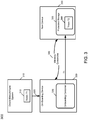
- FIG. 3 is a block diagram of another ownership transfer method in accordance with an embodiment.
- an out-of-band (OOB) channel may be used by a manufacturer to share an owner transfer token with an owner's loT device on-boarding tool.
- OOB out-of-band
- FIG. 3 shows a network architecture 300 that includes a device manufacturer system 310, which may be a given system of a device manufacturer that manufactures an loT device 350.
- a further system 330 is an on-boarding device for an loT network in which device 350 is to be provisioned.
- device 350 is a new device to be provisioned into the loT network and arrives in an unowned state.
- device 350 may store a token 360 (T2) provisioned by the device manufacturer during the manufacturing process, which may include the same value as a token to be provided to system 330, as discussed below.
- T2 token 360
- device manufacturer 310 provides a token 315 (T1) to on-boarding device 330.
- this communication of the token may be via an out-of-band (OOB) channel 320, which may take different forms.
- this token T1 may be an EPID or an asymmetric key to sign a Diffie-Hellmann exchange.
- a certificate may be provided with an EPID for an unowned device group.
- This token may be stored in an on-boarding container 335, which may be a given TEE of the device.
- a communication channel 340 is established between on-boarding device 330 and device 350.
- this communication channel may be a wireless communication channel.
- the channel may be used, after establishment of a session, to provide the token T1 to device 350, e.g., via a Diffie-Hellmann exchange.
- a device ownership transfer method as described herein may be performed. More specifically, assuming that device 350 confirms that the received token T1 includes the same value (e.g., PIN, random number or so forth) as its stored token 360 (T2), it is determined that system 330 may be trusted and an ownership transfer may validly occur, such that new device 350 self-asserts that it is now in an un-owned state.
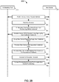
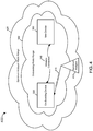
- FIG. 4 is a method of using a spectrum analyzer to deliver early warning notification of a possible wireless MITM attacker during an loT device on-boarding operation in accordance with an embodiment.
- the new device establishes that the entity that successfully completed on-boarding is its intended device owner. The device then disables the possibility of owner establishment.
- network 400 includes a first radio range 420 and a second radio range 380.
- radio range 420 has a larger range, namely the range in which signals can be detected by a spectrum analyzer 410.
- radio range 380 has a smaller range and may be an on-boarding radio range, namely the range of wireless communication, e.g., in a wireless local area network 340 such as a BluetoothTM low energy network or other short-range wireless network in which an on-boarding device 330 and a new device 350 are located.
- These devices may participate in an on-boarding and provisioning process, such as described herein in which device ownership is established within device 350.
- spectrum analyzer 410 may send notifications to on-boarding device 330, if unknown wireless signal activity is detected within radio range 420. In this way, if unknown or expected attacker-based wireless signaling is detected within radio range 420, spectrum analyzer 410 may issue one or more notifications to on-boarding tool 330 regarding spurious radio interference. Responsive to this information, on-boarding device 330 may take various appropriate actions, including signal strength modulation of one or more of devices 330 and 350. Such modulation may reduce the power or intensity of the wireless communications so that they do not communicate in the broader area of radio range 420. Understand that in some cases, the signal strength modulation may include preventing owner transfer communications, at least until the spectrum analyzer 410 indicates that the potential threat has been removed.
- a /oic/sec/doxm resource may contain the set of supported device owner transfer methods.
- Security resource are discoverable through a /oic/res resource.
- Resource discovery processing respects constraints (e.g., CRUDN) supplied as part of given security resource definitions.
- Table 3 is an owner transfer method resource definition in accordance with an embodiment of the present invention.
- Table 3 Fixed URI Resource Type Title Resource Type ID ("rt" value) Interfaces Description Related Functional Interaction /oic/sec/doxm Device Owner Transfer Methods urn:oic.sec.doxm Resource for supporting device owner transfer Configuration
- Table 4 is an example owner transfer method properties definition in accordance with an embodiment of the present invention, where an existing device interaction protocol may be used to query device owner status and configuration.
- Table 4 Property Name Operation Instance Mandatory Type Range Description Oxm R Multiple Yes OxmType - URN identifying the organization defining the owner transfer method and the method name.
- the owner transfer method resource contains an ordered list of owner transfer methods where the first entry in the list is the highest priority method and the last entry the lowest priority.
- the device manufacturer may configure this resource, e.g., with the most desirable (most secure) methods with high priority and least desirable with low priority.
- the network management tool may query this list at the time of on-boarding when the network management tool selects the most appropriate method. Subsequent to an owner transfer method being chosen, the agreed upon method is entered into the /doxm resource using the OxmSel property.
- owner transfer methods include two parts, a URN identifying the vendor or organization and the specific method.
- a Secure Resource Manager (SRM) generates a device identifier (DeviceID) that is stored in the /oic/sec/doxm resource in response to successful ownership transfer.
- Owner transfer methods may communicate the DevicelD to the service that is taking ownership.
- the service may associate the DevicelD with the OwnerPSK in a secured database.
- a bootstrap service may change the owned state to '0' (FALSE).
- Table 5 shows owner transfer methods in accordance with an embodiment.
- Table 5 Value Type Name Value Type URN Enumeration Value Description OICJustWorks urn:oic:oic"sec.doxm.jw 0
- the just works method relies on anonymous Diffie-Hellman exchange to realize a shared secret. It is subject to man-in-the-middle threats.
- the shared PIN method relies on an out-of-band PIN distribution method to generate a shared secret that mitigates many man-in-the-middle threats.
- a sign-and-MAC protocol may be used in performing a device owner transfer method.
- Table 6 shows a high level view of an example Intel® Sigma-based Diffie-Hellman exchange used in performing a device owner transfer for loT devices.
- a combination of owner transfer authorization factors are exchanged including a proximity PIN, plus an attestation hash of the new device's trusted execution environment configuration, plus a signature of the DH messages using an EPID signing key. Understand other embodiments are not limited to EPID signing.
- Tables 7 and 8, following Table 6, describe further details of an on-boarding sequence of such a device owner transfer as described in FIG. 2B .
- a network analyzer may inform the owner transfer endpoint of possible MITM attacks on wireless networks.
- a manufacturer-issued token that may be supplied in an loT device in secure memory, and an out-of-band channel (such as product packaging, QR code, IM, text, email, CDROM, post card or social media) may be used to communicate the token value.
- a token is input to a Diffie-Hellman key agreement protocol, where the secure DH endpoint is also the secure storage endpoint.
- the comparison of the token value obtained through the out-of-band channel is securely delivered to the secure storage endpoint and compared with the embedded token value to determine that the device ownership is established.
- a TEE may be used to securely process the DH endpoint, protect the token value and to maintain/update the device owner state.
- an loT resource framework may be used to represent the device owner transfer protocol and status to another loT device using the native messaging protocol of the other loT device.
- Embodiments enable use of a wireless spectrum analyzer to inform an owner transfer endpoint of possible wireless MITM attacker when computing a Diffie-Hellman key agreement protocol.
- a manufacturer token may optionally be used to assert ownership transfer of a device when the token is communicated to an intended owner over an out-of-band channel.
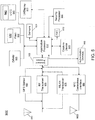
- system 900 may be a smartphone or other wireless communicator or any other loT device.
- a baseband processor 905 is configured to perform various signal processing with regard to communication signals to be transmitted from or received by the system.
- baseband processor 905 is coupled to an application processor 910, which may be a main CPU of the system to execute an OS and other system software, in addition to user applications such as many well-known social media and multimedia apps.
- Application processor 910 may further be configured to perform a variety of other computing operations for the device.
- application processor 910 can couple to a user interface/display 920, e.g., a touch screen display.
- application processor 910 may couple to a memory system including a non-volatile memory, namely a flash memory 930 and a system memory, namely a DRAM 935.
- flash memory 930 may include a secure portion 932 in which secrets and other sensitive information may be stored.
- application processor 910 also couples to a capture device 945 such as one or more image capture devices that can record video and/or still images.
- a universal integrated circuit card (UICC) 940 comprises a subscriber identity module, which in some embodiments includes a secure storage 942 to store secure user information.
- System 900 may further include a security processor 950 that may that may implement a TEE as described earlier, and which may couple to application processor 910.
- application processor 910 may implement a secure mode of operation, such as Intel® SGX for hosting of a TEE, as described earlier.
- a plurality of sensors 925 including one or more multi-axis accelerometers may couple to application processor 910 to enable input of a variety of sensed information such as motion and other environmental information.
- one or more authentication devices 995 may be used to receive, e.g., user biometric input for use in authentication operations.
- a near field communication (NFC) contactless interface 960 is provided that communicates in a NFC near field via an NFC antenna 965. While separate antennae are shown in FIG. 5 , understand that in some implementations one antenna or a different set of antennae may be provided to enable various wireless functionality.
- NFC near field communication
- a power management integrated circuit (PMIC) 915 couples to application processor 910 to perform platform level power management. To this end, PMIC 915 may issue power management requests to application processor 910 to enter certain low power states as desired. Furthermore, based on platform constraints, PMIC 915 may also control the power level of other components of system 900.
- PMIC power management integrated circuit
- a radio frequency (RF) transceiver 970 and a wireless local area network (WLAN) transceiver 975 may be present.
- RF transceiver 970 may be used to receive and transmit wireless data and calls according to a given wireless communication protocol such as 3G or 4G wireless communication protocol such as in accordance with a code division multiple access (CDMA), global system for mobile communication (GSM), long term evolution (LTE) or other protocol.
- CDMA code division multiple access
- GSM global system for mobile communication
- LTE long term evolution
- GPS sensor 980 may be present, with location information being provided to security processor 950 for use as described herein when context information is to be used in a pairing process.
- wireless communications such as receipt or transmission of radio signals, e.g., AM/FM and other signals may also be provided.
- WLAN transceiver 975 local wireless communications, such as according to a BluetoothTM or IEEE 802.11 standard can also be realized.
- multiprocessor system 1000 is a point-to-point interconnect system such as a server system, and includes a first processor 1070 and a second processor 1080 coupled via a point-to-point interconnect 1050.
- processors 1070 and 1080 may be multicore processors such as SoCs, including first and second processor cores (i.e., processor cores 1074a and 1074b and processor cores 1084a and 1084b), although potentially many more cores may be present in the processors.
- processors 1070 and 1080 each may include a secure engine 1075 and 1085 to perform security operations such as attestations, loT network on-boarding or so forth.
- first processor 1070 further includes a memory controller hub (MCH) 1072 and point-to-point (P-P) interfaces 1076 and 1078.
- second processor 1080 includes a MCH 1082 and P-P interfaces 1086 and 1088.
- MCH's 1072 and 1082 couple the processors to respective memories, namely a memory 1032 and a memory 1034, which may be portions of main memory (e.g., a DRAM) locally attached to the respective processors.
- First processor 1070 and second processor 1080 may be coupled to a chipset 1090 via P-P interconnects 1052 and 1054, respectively.
- chipset 1090 includes P-P interfaces 1094 and 1098.
- chipset 1090 includes an interface 1092 to couple chipset 1090 with a high performance graphics engine 1038, by a P-P interconnect 1039.
- chipset 1090 may be coupled to a first bus 1016 via an interface 1096.
- various input/output (I/O) devices 1014 may be coupled to first bus 1016, along with a bus bridge 1018 which couples first bus 1016 to a second bus 1020.
- Various devices may be coupled to second bus 1020 including, for example, a keyboard/mouse 1022, communication devices 1026 and a data storage unit 1028 such as a non-volatile storage or other mass storage device.
- data storage unit 1028 may include code 1030, in one embodiment.
- data storage unit 1028 also includes a trusted storage 1029 to store sensitive information to be protected.
- an audio I/O 1024 may be coupled to second bus 1020.
- module 1300 may be an Intel® CurieTM module that includes multiple components adapted within a single small module that can be implemented as all or part of a wearable device.
- module 1300 includes a core 1310 (of course in other embodiments more than one core may be present).
- core 1310 may be a relatively low complexity in-order core, such as based on an Intel Architecture® QuarkTM design.
- core 1310 may implement a TEE as described herein.
- Core 1310 couples to various components including a sensor hub 1320, which may be configured to interact with a plurality of sensors 1380, such as one or more biometric, motion environmental or other sensors.
- a power delivery circuit 1330 is present, along with a non-volatile storage 1340.
- this circuit may include a rechargeable battery and a recharging circuit, which may in one embodiment receive charging power wirelessly.
- One or more input/output (IO) interfaces 1350 such as one or more interfaces compatible with one or more of USB/SPI/I 2 C/GPIO protocols, may be present.
- IO input/output
- a wireless transceiver 1390 which may be a BluetoothTM low energy or other short-range wireless transceiver is present to enable wireless communications as described herein. Understand that in different implementations a wearable module can take many other forms.
- a system comprises: a first device having at least one processor and a secure storage and having a first TEE; and an on-boarding system coupled to the first device within a first network.
- the on-boarding system may include a second TEE, and may receive a request to transfer ownership of the first device to a new owner, receive notification information from a spectrum analyzer regarding wireless signal information within the first network, and perform a native communication protocol between the on-boarding system and the first device to communicate ownership information to execute the ownership transfer to the new owner, to cause the first device to store the ownership information in a storage of the first device.
- the on-boarding system is to receive a first token from a manufacturer of the first device and provide the first token to the first device.
- the first device comprises an loT device and which is to compare the first token to a stored token, and update an ownership indicator of the first device to indicate that the first device is owned, based at least in part on the comparison.
- Example 4 the first device is to be introduced into the first network in an unowned state.
- the native communication protocol comprises a predetermined communication protocol to enable non-owner transfer communications.
- the native communication protocol comprises an in-band communication between the on-boarding system and the first device.
- Example 7 the first device is to self-assert that it is to be owned by the new owner, without reliance on the on-boarding system.
- the native communication protocol includes establishment of a Diffie-Hellmann session between the on-boarding system and the first device, to establish an owner pre-shared key.
- Example 9 the native communication protocol includes a secure session to be established using the owner pre-shared key.
- the on-boarding system is to: instruct the first device regarding a provisioning technique for the ownership transfer; calculate the owner pre-shared key and compare the calculated owner pre-shared key to a received pre-shared key, establish a secure provisioning channel between the on-boarding system and the first device using the owner pre-shared key; and provision the first device with one or more resources via the secure provisioning channel.
- Example 11 the native communication protocol includes a shared PIN process to execute the ownership transfer.
- Example 12 the first device is to self-assert ownership by the new owner during the secure session.
- the on-boarding system is to determine if a potential attacker is within a radio range of the first network based on the wireless signal information, and responsive to the determination that the potential attacker is within the radio range, manipulate a signal strength of the on-boarding system and the first device, to limit an emission range of the on-boarding system and the first device.
- a method comprises: receiving, in an on-boarding system for a first network, a request to transfer ownership of a first device having a trusted execution environment to a new owner; receiving, in the on-boarding system, notification information from a spectrum analyzer regarding wireless signal information within the first network; determining if a potential attacker is within a radio range of the first network based on the wireless signal information; responsive to determining that the potential attacker is within the radio range, manipulating a signal strength of the on-boarding system and the first device, to limit an emission range of the on-boarding system and the first device; and performing a native communication protocol between the on-boarding system and the first device to communicate ownership information to execute the ownership transfer to the new owner, to enable the first device to store the ownership information in a storage of the first device.
- Example 15 the method further comprises receiving, in the on-boarding system, a first token via an out-of-band channel, from a manufacturer of the first device; and sending the first token to the first device via a secure channel.
- the first device responsive to receipt of the first token, is to compare the first token to a stored token present in a secure storage of the first device, the stored token stored by the manufacturer of the first device, and update an owner status, based at least in part on the comparison.
- Example 17 the method further comprises preventing the ownership information communication responsive to the radio range determination.
- a method comprises: establishing a first secure session between an on-boarding system of an loT network and a device to be introduced into the loT network, the device in an unowned state at the introduction; computing an owner PSK in the device in the first secure session, storing the owner PSK in a storage of the device, and thereafter terminating the first secure session; establishing a second secure session between the on-boarding system and the device, using the owner PSK; and responsive to successfully establishing the second secure session, autonomously updating an ownership state of the device to an owned state.
- Example 19 the method further comprises: receiving a command from the on-boarding system to manipulate a signal strength of the device; and responsive to receiving the command, reducing a signal level of a wireless channel of the first secure session to limit an emission range of the device.
- Example 20 the method further comprises: receiving a first token from the on-boarding system, the first token received in the on-boarding system from a manufacturer of the device via an out-of-band channel; comparing the first token to a stored token stored in a secure storage of the device, the stored token stored by the manufacturer of the device; and updating the ownership state of the device, based at least in part on the comparison.
- a computer readable medium including instructions is to perform the method of any of the above Examples.
- a computer readable medium including data is to be used by at least one machine to fabricate at least one integrated circuit to perform the method of any one of the above Examples.
- an apparatus comprises means for performing the method of any one of the above Examples.
- a system comprises: means for receiving a request to transfer ownership of a first device having a trusted execution environment to a new owner; means for receiving notification information from a spectrum analyzer regarding wireless signal information within the a network; means for determining if a potential attacker is within a radio range of the first network based on the wireless signal information; means for manipulating a signal strength of the system and the first device, to limit an emission range of the system and the first device, responsive to determining that the potential attacker is within the radio range; and means for performing a native communication protocol between the system and the first device to communicate ownership information to execute the ownership transfer to the new owner, to enable the first device to store the ownership information in a storage of the first device.
- Example 22 the system further comprises means for receiving a first token via an out-of-band channel, from a manufacturer of the first device; and means for sending the first token to the first device via a secure channel.
- Example 23 the system further comprises means for preventing the ownership information communication responsive to the radio range determination.
- Embodiments may be used in many different types of systems.
- a communication device can be arranged to perform the various methods and techniques described herein.
- the scope of the present invention is not limited to a communication device, and instead other embodiments can be directed to other types of apparatus for processing instructions, or one or more machine readable media including instructions that in response to being executed on a computing device, cause the device to carry out one or more of the methods and techniques described herein.
- Embodiments may be implemented in code and may be stored on a non-transitory storage medium having stored thereon instructions which can be used to program a system to perform the instructions. Embodiments also may be implemented in data and may be stored on a non-transitory storage medium, which if used by at least one machine, causes the at least one machine to fabricate at least one integrated circuit to perform one or more operations.
- the storage medium may include, but is not limited to, any type of disk including floppy disks, optical disks, solid state drives (SSDs), compact disk read-only memories (CD-ROMs), compact disk rewritables (CD-RWs), and magneto-optical disks, semiconductor devices such as read-only memories (ROMs), random access memories (RAMs) such as dynamic random access memories (DRAMs), static random access memories (SRAMs), erasable programmable read-only memories (EPROMs), flash memories, electrically erasable programmable read-only memories (EEPROMs), magnetic or optical cards, or any other type of media suitable for storing electronic instructions.
- ROMs read-only memories
- RAMs random access memories
- DRAMs dynamic random access memories
- SRAMs static random access memories
- EPROMs erasable programmable read-only memories
- EEPROMs electrically erasable programmable read-only memories
- magnetic or optical cards or any other type of media suitable for storing electronic instructions.
Description
- Establishing trust in an Internet of Things (loT) device is a challenge facing the emerging Internet-of-Things networks because the added attack surface presented by loT networks raises the probability that attackers may find ways to infiltrate and weaken or compromise both loT as well as traditional cyber networks. Mechanisms for establishing trust range from add-on security monitoring applications that attempt to observe devices from within the device or over a network connection. Such observations are based in the philosophy that the observing components are not attackable by malware within the network. Still other approaches integrate trusted computing modules which can undesirably increase cost that make such approaches unfeasible.
- D1 describes a device ownership transfer from a network. A home relationship is established between a device and a network by storing an ownership record in the device that identifies the network, and storing in the network a device identifier that identifiers the device. Thereafter, communication is established between the device and the network. The ownership record is then transmitted from the network to the device, and automatic access to the device is granted to the network once the device verifies the transmitted ownership record stored in the device.
- In OSCAR GARCIA-MORCHON et. al: "Securing the IP-based internet of things with HIP and DTLS", SECURITY AND PRIVACY IN WIRELESS AND MOBILE NETWORKS, April 2013, pages 119-124, as DTLS runs on the transport layer, it can be used directly to protect the applications. The polynomial shares are also used here to provide for fast pairwise key agreement between any pair of devices in the IoT domain. This pairwise key serves as the PSK in DTLS-PSK enabling any two applications running on the devices to derive a session key, equivalent to the TEK in the HIP-approach.
- The object of the present invention is solved by the subject-matter of the independent claims, wherein further embodiments are incorporated in the dependent claims.
-
-
FIG. 1 is a diagram illustrating an on-boarding and owner transfer method, in accordance with an embodiment. -
FIG. 2A is a diagram illustrating an on-boarding and owner transfer method in accordance with another embodiment. -
FIG. 2B is a diagram illustrating an on-boarding and owner transfer method in accordance with yet another embodiment of the present invention -
FIG. 3 is a block diagram of another ownership transfer method in accordance with an embodiment. -
FIG. 4 is a method of using a spectrum analyzer to deliver early warning notification in accordance with an embodiment. -
FIG. 5 is a block diagram of an example system with which embodiments can be used. -
FIG. 6 is a block diagram of a system in accordance with another embodiment of the present invention. -
FIG. 7 is a block diagram of a wearable module in accordance with another embodiment. - In various embodiments, an loT device may be configured to be a trusted device. To this end, embodiments may re-factor trusted computing techniques to be applied to loT devices directly, where the basis for trust is established by the device itself and the protocols for on-boarding the device into an loT network. Embodiments may provide protocols for on-boarding loT devices, where such devices may take advantage of trusted computing methods traditionally reserved for security coprocessors and other security augmentation technologies. Specifically, embodiments may securely transfer a device owner status established by a manufacturer to a device owner. Note that the term "on-boarding" refers to a process through which a device is introduced into an owner's environment. As part of overall on-boarding, a device may have securely transferred ownership from a previous owner or manufacturer to the intended owner. Owner transfer can be a point of attack since it may be difficult to detect this attack subsequently. In an embodiment, this on-boarding approach may reuse an loT device resource model so that the infrastructure used to process normal loT functions may also be used to perform secure on-boarding, which may be more efficient than defining separate security messaging, interfaces and data structures. In this way, loT devices can achieve a higher level of trust than otherwise possible.
- Embodiments provide a protocol and operational duties performed by a device manufacturer and user to establish a security context in which device owner transfer may occur. An loT device may determine when appropriate conditions are met to declare when ownership is established. In contrast, traditional approaches assume devices are slaves to an authoritative service that declares the device is owned and trusted. Embodiments enable device developers to include device owner transfer logic in an loT device so that the most authoritative assertion of device ownership is self-asserted.
- In various embodiments, security relevant device on-boarding status is represented using a resource abstraction model used by loT frameworks (e.g., Open Interconnect Consortium (OIC), OMA) to capture device ownership transfer state changes. This approach allows the framework to accurately maintain and represent to other devices its ownership status without having a sideband or security specific representation. Embodiments result in a set of device on-boarding flows expressed in the native device interaction scripting that implements the intended device owner transfer protocols without introducing a separate trusted protocol messaging stack and interface. Trust is established by orchestrating bootstrap sequences such that the device does not enter an insecure state during on-boarding. Embodiments may define explicit on-boarding sequences resulting in device owner transfer from a trusted manufacturer to the intended consumer/owner. Understand that while example embodiments herein relate to devices to communicate with protocols compatible with Open Interconnect Consortium arrangements, the general ownership transfer protocol described herein applies to many other loT examples.
- In embodiments, a pre-shared key, called the "OwnerPSK," may be established when the new device is introduced into an owner's network. The OwnerPSK (one per device) is the result of an out-of-band transfer of ownership method between the previous owner/manufacturer and the new owner (a device owner transfer method (DOXM)). Different embodiments herein may produce a pre-shared key value that is used to assert device ownership. The OwnerPSK is used to generate (e.g.,) symmetric keys that are used for other purposes. For example, a pair-wise PSK can be used to protect device-provisioning data from a system management tool. In one embodiment, the OwnerPSK generation method may be as follows, as an example. OwnerPSK = PRF(Random, DeviceLabel, NewOwnerLabel, PreviousOwnerLabel), where: PRF is a pseudo-random function used for key generation that cryptographically combines function parameters such that it exhibits pre-image resistance, collision resistance and second pre-image resistance; Random is a random value with sufficient entropy; DeviceLabel identifies the device whose ownership is being transferred; NewOwnerLabel is a value supplied by the new owner acknowledging the intent to become the new owner; and PreviousOwnerLabel is a value supplied by the previous owner acknowledging the intent to transfer ownership to the new owner. If the platform contains a platform ownership capability such that multiple OIC device instances hosted on the same platform would not require taking ownership subsequent to the first OIC device instance, the NewOwnerLabel identifies the platform ownership method and may reference the platform owner authorization data. The NewOwnerLabel values may be shared between OIC device and owner transfer service to facilitate OwnerPSK computation using the pseudo-random function.
- In different embodiments, the OwnerPSK value may have the following formats in different examples, shown in Tables 1 and 2.
Table 1 128-bit key: Name Value Type Description Length 16 OCTET Specifies the number of 8-bit octets following Length. Key opaque OCTET Array 16 byte array of octets. When used as input to a PSK function Length is omitted. Table 2 256-bit key: Name Value Type Description Length 32 OCTET Specifies the number of 8-bit octets following Length. Key opaque OCTET Array 32 byte array of octets. When used as input to a PSK function Length is omitted. - In different embodiments, various modes of device owner self-assertion may be realized. In a first embodiment, a protocol between a device on-boarding tool and a device owned by a manufacturer may be used. Referring now to
FIG. 1 , shown is a diagram illustrating an on-boarding and owner transfer method relying on a manufacturer-supplied token that is an indication of the intent to transfer ownership, in accordance with an embodiment. - In this embodiment, the manufacturer supplies an ownership transfer token via an out-of-band channel and the verification of the token is achieved by comparing the token with an embedded copy stored in a protected memory within the device. The protocol depends on a Diffie-Hellman key agreement protocol to dynamically establish a secure connection without dependence on a common public key infrastructure (PKI) that issues certificates or some other third party that is presumed to be trusted by both parties. Often, such third parties do not exist in practice hence only serve to confuse actual security semantics of device owner transfer logic. This not intended to suggest that use of a PKI, certificates or asymmetric cryptography may not be used in the construction of a secure session based on a key agreement protocol such as Diffie-Hellman, as described in
FIG. 2B , below. -
FIG. 1 shows a set of interactions between an on-boarding tool 110 (which may be a server or other computing system of an loT network owner) and anew device 120 to be incorporated into a given loT network (e.g., any given type of loT computing device) in anenvironment 100. To enable on-boarding of the new device and to update ownership, e.g., to a common entity that owns on-boarding tool 110 and the loT network, a deviceowner transfer method 130 is shown. In the embodiment ofFIG. 1 , deviceowner transfer method 130 provides a sequence of communications to enable ownership establishment of a device that is previously in an unowned state (e.g., as originally configured by a manufacturer of the device). The embodiment ofFIG. 1 provides amethod 130 to perform a shared PIN device owner transfer method. - In general,
method 130 shown inFIG. 1 includes a process for establishing an owner pre-shared key (PSK), e.g., via a Diffie-Hellmann exchange process. The devices may perform a negotiation or discovery of the device to be on-boarded, and perform a process to enable the device to verify that the on-boarding tool is authentic and trusted, such that after a first session is established to generate the owner PSK and then terminated, a secure provisioning channel can be established using this owner PSK. This establishment of a secure channel thus indicates to the device that the on-boarding tool can be trusted and a valid exchange of a set of credentials to be shared between the devices can occur. In addition, assuming the process is correctly performed, the device can self-assert that it is now owned. - To begin
method 130, new devices are found (block 135). Note that each of the following numbered communications is a given communication of a portion of an owner transfer process between on-boarding tool 110 andnew device 120. Further, for each portion of the processor the first communication may be sent from on-boarding tool 110 tonew device 120, and the last communication fromnew device 120 to on-boarding tool 110, unless otherwise stated. - 1. GET/oic/sec/doxm?Owned="FALSE"
- 2. RSP ({*OxmType":"oic.sec.doxm.pin*, "Oxm": "0", "Owned":"FALSE", "DidFormat": "0", "DeviceID":"uuidA2IC-EOOO-0000-0000*....})
- 3. POST/oic/sec/doxm ({..."OxmSel": "oic.sec.doxm.pin",...})
- 4. RSP 2.04
- 5. GET/oic/sec/pstat
- 6. RSP ({"lsOp":"FALSE", "Cm": "bx0011.1110", "Tm": "bx0011.1110, "DeviceID":, "Om" : "bx0000,0000", "Sm": "bx0000,0011", "CommitHash":})
- Next, at
block 140 the on-boarding tool instructs the new device how provisioning will be achieved. In an embodiment, the following messages may be sent. - 7. PUT/oic/sec/pstat ({....,"Om": "bx0000,0011",...})
- 8. RSP 2.04
- Next at
block 150, a secure device owner shared PIN method may be performed. In an embodiment, this method may be performed based on the PSK. Understand that in other situations an asymmetric credential could be used. In an embodiment, the communications to perform this portion of the process include: - 9. ClientHello(TLS_ECDHE_PSK_WITH_AES_128_CBC_SHA)
- 10. HelloVerifyRequest(cookie)
- 11. ClientHello(cookie)
- 12. ServerHello(); ServerKeyExchange(ECDH PublicKey + ECC Curve Param); ServerHelloDone()
- Next at block 155 a pre-shared key can be computed, e.g., according to a password-based key derivation function, such as: PBKDF2(PRF, PIN, new device ID, dklen), described further below. In an embodiment, a Diffie-Hellmann process may be performed to establish this pre-shared key. This operation defines a PIN that may be used with a DH construction of G a' and G b' values, where a' = a+PIN and b'= b+PIN. The a' and b' values can be found only if the PIN value is known to both endpoints. This can happen if the PIN is communicated over an out-of-band channel that establishes physical proximity. For example, one proximity implementation is an ultrasonic speaker/microphone to communicate a PIN where physical barriers may prevent an unauthorized listener from hearing/recording the PIN broadcast. Hence it is resistant to some attacks where the attacker cannot be physically proximal to the endpoints. In an embodiment, communications for this computation may include:
- 13. ClientKeyExchange(ECDH PublicKey); ChangeCipherSpec + Finish
- 14. ChangeCipherSpec + Finish
- 15. PUT/oic/sec/doxm ({...,"DevOwner": "uuid:B0B0-0000-0000-0000",....})
- 16. RSP2.04
- Thereafter, at
block 160 both sides compute the owner PSK. In an embodiment, on-boarding tool 110 may compute the owner PSK as follows: - 17. OwnerPSK = PRF(MasterSecret, "oic.sec.doxm.jw", "uuid:B0B0-0000-0000-0000", "uuid:A21C-E000-0000-0000", "63"). This method thus avoids use of a PIN to compute G a and G b . However, a PRF construction for PIN may be similar, substituting "...doxm.jw" for "...doxm.rdp," implying the PIN method was used/intended.
- And in turn,
new device 120 may compute the owner PSK as follows: - 18. OwnerPsk = PRF(...)
- 19. /oic/sec/pstat.Cm=bx0011,1100. Note at this point, the session may be terminated.
- Thereafter, the owner PSK may be used to establish a new session having a secure provisioning channel, which in an embodiment may be a DTLS session (block 170). The session may be opened in both directions using the owner PSK as the pre-shared key provided to a supplied cipher suite, in one embodiment as follows:
- 20. Open DTLS session with OwnerPSK as the PSK for TL5_PSK_...cipher suite.
- At
block 180, the owner PSK may be used to construct a DTLS session to verify correct computation of the owner PSK. In this operation, note thatnew device 120 may self-assert that the device is now placed into an owned state. As such, this ownership change of state is initiated and performed solely withinnew device 120, without reliance on on-boarding tool 110. In this way, a device itself manages its own ownership state autonomously In an embodiment, the new device may set an owner status according to: - 21. /oic/sec/doxm.Owned= "TRUE."
- Thereafter, a provisioning process may be performed in the secure session to provision the new device with supported credentials. First at
block 185, the onboarding tool may querynew device 120 for supported credential types (block 185). Next atblock 186, the new device is provisioned with supported credential types. In an embodiment and based upon the supported credential types these credentials may include provisioning of: symmetric-pairwise, symmetric-groupwise, asymmetric-pairwise, and/or asymmetric-groupwise credentials. Note further that the supported credentials may further include credentials for provisioning services that may be used to continue/complete provisioning of an loT device. Thereafter, atblock 190, the new device may be provisioned with various resources. For example, a network security service may provision additional security credentials for accessing other services and devices. It may further provision Access Control Lists (ACL) and other policies. In some embodiments, device management settings, software/firmware updates, and so forth, also may be provisioned. Thereafter, the DTLS session may be closed. - In one embodiment, the PIN-based device owner transfer method of
FIG. 1 uses a pseudo-random function (e.g., PBKDF2) defined by Request for Comments (RFC) 2898 and a PIN exchanged via an out-of-band method to generate the pre-shared key. The PIN-authenticated pre-shared key (PPSK) is supplied to a given TLS ciphersuite that accepts a PSK as follows:
PPSK = PBKDF2(PRF, PIN, DevicelD, c, dkLen), where the PBKDF2 function has the following parameters: - PRF - Uses the DTLS PRF;
- PIN - obtain via out-of-band channel;
- DevicelD - UUID of the new device;
- c - Iteration count initialized to 1000, incremented upon each use; and
- dkLen - Desired length of the derived PSK in octets.
- Referring now to
FIG. 2A , shown is a diagram illustrating an on-boarding and owner transfer method in accordance with another embodiment. In this configuration, an embodiment may rely on a spectrum analyzer for notification of signal intelligence warning of possible MITM threats to a Diffie-Hellman-based owner transfer method. - In the embodiment of
FIG. 2A , an anonymous Diffie-Hellman key agreement protocol may be used to arrive at symmetric keys that are input to the OwnerPSK calculation. In this embodiment, an OwnerPSK calculation may follow the following format to ensure interoperability across different vendor products:
OwnerPSK = PRF(MasterSecret, Message, Length), where: - PRF uses a TLS PRF defined by RFC5246;
- MasterSecret is the master secret key resulting from the DTLS handshake;
- Message is a concatenation of the following:
- DoxmType string for the Just Works method (e.g. "oic.sec.doxm.jw");
- OwnerlD is a URI identifying the device owner identifier and the device that maintains OwnerPSK;
- DevicelD is new device's DevicelD (e.g. "urn:uuid:XXXX-XXXX-XXXX-XXXX"); and
- Length is the length of Message in octets.
- As with
FIG. 1 ,FIG. 2A shows a set of interactions between an on-boarding tool 210 and anew device 220 that occur in anenvironment 200. In the embodiment ofFIG. 2A , deviceowner transfer method 230 provides a sequence of communications to enable ownership establishment of this new device that is on-boarded into a network in an unowned state. More specifically, the embodiment ofFIG. 2A providesmethod 230 for performing a "JustWorks" device owner transfer method. - To begin
method 230, new devices are found (block 235). In one embodiment, the following operations are included. - 1. GET/oic/sec/doxm?Owned="FALSE"
- 2. RSP ({*OxmType":"oic.sec.doxm.jw", "Oxm": "0", "Owned":"FALSE", "DidFormat": "0", "DeviceID":"uuidA2IC-EOOO-0000-0000*....})
- 3. POST/oic/sec/doxm ({... "OxmSel": "oic.sec.doxm.jw",...})
- 4. RSP 2.04
- 5. GET/oic/sec/pstat
- 6. RSP ({"IsOp":"FALSE", "Cm": "bx0011.1110", "Tm": "bx0011.1110, "DeviceID":, "Om" : "bx0000,0000", "Sm": "bx0000,0011", "CommitHash":})
- Next at
block 240 the on-boarding tool instructs the new device how provisioning will be achieved. In an embodiment, the following messages may be sent. - 7. PUT/oic/sec/pstat ({....,"Om": "bx0000,0011",...})
- 8. RSP 2.04
- Next at block 250 a secure device owner JustWorks method may be performed. In an embodiment, the communications to perform this portion of the process include:
- 9. ClientHello(TLS_ECDH_anon_WITH_AES_128_CBC_SHA)
- 10. HelloVerifyRequest()
- 11. ClientHello(cookie)
- 12. ServerHello(); ServerKeyExchange(ECDH PublicKey + ECC Curve Param); ServerHelloDone()
- 13. ClientKeyExchange(ECDH PublicKey); ChangeCipherSpec + Finish
- 14. ChangeCipherSpec + Finish
- 15. PUT/oic/sec/doxm ({...,"DevOwner": "uuid:B0B0-0000-0000-0000",....})
- 16. RSP 2.04
- Understand that in other embodiments another configuration suite that selects different algorithms employing an anonymous Diffie-Hellman protocol may be used, where an ephemeral elliptic-curve method, counter-based cipher block mode (e.g., CCM, GCM) or other encryption mode or SHA256 or other cryptographic hash may be used.
- Next at
block 260, the owner PSK can be computed by both sides. In an embodiment, on-boarding tool 210 may compute the owner PSK as follows: - 17. OwnerPSK = PRF(MasterSecret, "oic.sec.doxm.jw", "uuid:B0B0-0000-0000-0000", "uuid:A21C-E000-0000-0000", "63")
- And in turn,
new device 220 may compute the owner PSK as follows: - 18. OwnerPsk = PRF(...)
- 19. /oic/sec/pstat.Cm=bx0011,1100
- Then after termination of this first session, as above the owner PSK may be used to establish a new secure session having a secure provisioning channel (block 270) in which a DTLS session is constructed, and thereafter the new device may be provisioned with supported credentials and resources (
blocks - 20. Open DTLS session with OwnerPSK as the PSK for TL5_PSK_...cipher suite
- 21. /oic/sec/doxm.Owned= "TRUE"
- 22. Close DTLS Session
- In yet another embodiment, another owner transfer method may be used in which signing keys and certificate credentials may be used to establish a secure session. Referring now to
FIG. 2B , shown is a diagram illustrating an on-boarding and owner transfer method in accordance with yet another embodiment of the present invention. As shown inFIG. 2B , environment 200' includes similar on-boarding tool 210 andnew device 220. Note thatmethod 230 to perform a device owner transfer operation may proceed similarly as discussed above inFIG. 2A atblocks - Still with reference to
FIG. 2B , atblock 265 the new device may be queried by the on-boarding tool regarding supported credential types. Then atblock 275 the new device may be provisioned with supported credential types. Based on such supported credential types, symmetric-pair wise credentials (e.g., including an OwnerPSK), symmetric-groupwise, asymmetric-pairwise, and/or a symmetric-groupwise credentials may be provisioned. Note that such credentials may include credentials for provisioning services to be used to continue/complete loT device provisioning. Thereafter atblock 284 the new device is provisioned with settings for connection to a production loT network. Note that some settings may involve connecting to a different wireless access point or network interface which, in an embodiment, may use the credentials provisioned inblock 275. Thereafter atblock 294,new device 220 may connect to the production network. Then at block 296 the new device may contact one or more provisioning servers in this production network to continue/complete new device provisioning. - Embodiments may provide flexibility for manufacturers that do not have secure storage resources or manufacturing capability to embed a token value at manufacturing time. For this mode, the context of on-boarding can be relied upon. The legitimate device owner establishes the context for device owner transfer by evaluating the likelihood that a man in the middle (MITM) attacker might reasonably be able to conduct the MITM attack constantly over the life of the device. For example, if the device relies on wireless communication technology such as Bluetooth, NFC or WiFi, the MITM attacker would be required to maintain a wireless connection that prevents the on-boarding system from directly accessing the new device and ensures the new device only depends on the MITM device for access to other legitimate devices. In practice, this attack is quite challenging.
- The device owner may take additional steps to minimize the possibility of MITM attackers during on-boarding and ownership transfer. These operations may include manipulation of wireless broadcast signals to limit the radio range of both the new device and the on-boarding system. Additionally, the on-boarding environment may include a spectrum analysis device that monitors all wireless signals, ranking them accord to broadcast strength, origin and type. The on-boarding activity may be performed in the context of the signals' intelligence that may serve as an early warning mechanism and threat notification system. As an example, signal strength modulation of a wireless transmitting and receiving device may be used to minimize/mitigate the effectiveness of a MITM attack.
-
FIG. 3 is a block diagram of another ownership transfer method in accordance with an embodiment. InFIG. 3 , an out-of-band (OOB) channel may be used by a manufacturer to share an owner transfer token with an owner's loT device on-boarding tool. - As illustrated,
FIG. 3 shows anetwork architecture 300 that includes adevice manufacturer system 310, which may be a given system of a device manufacturer that manufactures anloT device 350. Afurther system 330 is an on-boarding device for an loT network in whichdevice 350 is to be provisioned. Assume thatdevice 350 is a new device to be provisioned into the loT network and arrives in an unowned state. In this un-owned state,device 350 may store a token 360 (T2) provisioned by the device manufacturer during the manufacturing process, which may include the same value as a token to be provided tosystem 330, as discussed below. - As seen in
arrangement 300,device manufacturer 310 provides a token 315 (T1) to on-boarding device 330. In an embodiment, this communication of the token may be via an out-of-band (OOB)channel 320, which may take different forms. Note that this token T1 may be an EPID or an asymmetric key to sign a Diffie-Hellmann exchange. In other cases, a certificate may be provided with an EPID for an unowned device group. This token may be stored in an on-boarding container 335, which may be a given TEE of the device. - As seen, a
communication channel 340 is established between on-boarding device 330 anddevice 350. In an embodiment, this communication channel may be a wireless communication channel. The channel may be used, after establishment of a session, to provide the token T1 todevice 350, e.g., via a Diffie-Hellmann exchange. Still further, a device ownership transfer method as described herein may be performed. More specifically, assuming thatdevice 350 confirms that the received token T1 includes the same value (e.g., PIN, random number or so forth) as its stored token 360 (T2), it is determined thatsystem 330 may be trusted and an ownership transfer may validly occur, such thatnew device 350 self-asserts that it is now in an un-owned state. -
FIG. 4 is a method of using a spectrum analyzer to deliver early warning notification of a possible wireless MITM attacker during an loT device on-boarding operation in accordance with an embodiment. Subsequent to on-boarding, the new device establishes that the entity that successfully completed on-boarding is its intended device owner. The device then disables the possibility of owner establishment. - Referring now to
FIG. 4 , illustrated is anetwork 400. As seen,network 400 includes afirst radio range 420 and asecond radio range 380. Note thatradio range 420 has a larger range, namely the range in which signals can be detected by aspectrum analyzer 410. In turn,radio range 380 has a smaller range and may be an on-boarding radio range, namely the range of wireless communication, e.g., in a wirelesslocal area network 340 such as a Bluetooth™ low energy network or other short-range wireless network in which an on-boarding device 330 and anew device 350 are located. These devices may participate in an on-boarding and provisioning process, such as described herein in which device ownership is established withindevice 350. To this end, to prevent unwanted intrusion,spectrum analyzer 410 may send notifications to on-boarding device 330, if unknown wireless signal activity is detected withinradio range 420. In this way, if unknown or expected attacker-based wireless signaling is detected withinradio range 420,spectrum analyzer 410 may issue one or more notifications to on-boarding tool 330 regarding spurious radio interference. Responsive to this information, on-boarding device 330 may take various appropriate actions, including signal strength modulation of one or more ofdevices radio range 420. Understand that in some cases, the signal strength modulation may include preventing owner transfer communications, at least until thespectrum analyzer 410 indicates that the potential threat has been removed. - In an embodiment for an OIC-compliant device, a /oic/sec/doxm resource may contain the set of supported device owner transfer methods. Security resource are discoverable through a /oic/res resource. Resource discovery processing respects constraints (e.g., CRUDN) supplied as part of given security resource definitions. Table 3 is an owner transfer method resource definition in accordance with an embodiment of the present invention.
Table 3 Fixed URI Resource Type Title Resource Type ID ("rt" value) Interfaces Description Related Functional Interaction /oic/sec/doxm Device Owner Transfer Methods urn:oic.sec.doxm Resource for supporting device owner transfer Configuration - Table 4 is an example owner transfer method properties definition in accordance with an embodiment of the present invention, where an existing device interaction protocol may be used to query device owner status and configuration.
Table 4 Property Name Operation Instance Mandatory Type Range Description Oxm R Multiple Yes OxmType - URN identifying the organization defining the owner transfer method and the method name. OxmSel R Single Yes OxmType - The Oxm that was selected for device ownership transfer. Owned R Single Yes Boolean TIF Indicates whether or not the device ownership has been established. FALSE indicates device is unowned. DidFormat R Single Yes UINT8 0-255 Enumerated device ID format. [0-URN] (e.g. urn:uuid:XXXX-XXXX-XXXX-XXXX) DevicelD R Single Yes OCTET[] - DevicelD assigned to this instance of the OIC framework. Did Format determines how to interpret the OCTET string DevOwner R Single Yes oic.sec.svc - URI identifying a service that is the device owner. This may be any value chosen by the device owner. Rowner R Single Yes oic.sec.svc - This resource's owner. Typically this is the bootstrap service that instantiated this resource. Supported Credential Types R Single Yes BITMASK - Bitmask of credential types this device can support. - As shown in Table 4, the owner transfer method resource contains an ordered list of owner transfer methods where the first entry in the list is the highest priority method and the last entry the lowest priority. The device manufacturer may configure this resource, e.g., with the most desirable (most secure) methods with high priority and least desirable with low priority. The network management tool may query this list at the time of on-boarding when the network management tool selects the most appropriate method. Subsequent to an owner transfer method being chosen, the agreed upon method is entered into the /doxm resource using the OxmSel property.
- In an embodiment, owner transfer methods include two parts, a URN identifying the vendor or organization and the specific method.
- <OxmType> ::= "urn:" <NID> ":" <NSS>
- <NID> :: = 1 <Vendor-Organization>
- <NSS> ::= <Method> | {<NameSpaceQualifier> "."} <Method>
- <NameSpaceQualifier> ::= String
- <Method> ::= String
- <Vendor-Organization> ::= String
- When an owner transfer method successfully completes, the Owned property is set to '1' (TRUE). Consequently, subsequent attempts to take ownership of the device will fail. A Secure Resource Manager (SRM) generates a device identifier (DeviceID) that is stored in the /oic/sec/doxm resource in response to successful ownership transfer. Owner transfer methods may communicate the DevicelD to the service that is taking ownership. The service may associate the DevicelD with the OwnerPSK in a secured database. Once owned, a bootstrap service may change the owned state to '0' (FALSE).
- Table 5 shows owner transfer methods in accordance with an embodiment.
Table 5 Value Type Name Value Type URN Enumeration Value Description OICJustWorks urn:oic:oic"sec.doxm.jw 0 The just works method relies on anonymous Diffie-Hellman exchange to realize a shared secret. It is subject to man-in-the-middle threats. OICSharedPin urn:oic:oic" sec.doxm.pin 1 The shared PIN method relies on an out-of-band PIN distribution method to generate a shared secret that mitigates many man-in-the-middle threats. - As discussed above, in some embodiments a sign-and-MAC protocol may be used in performing a device owner transfer method. Table 6 below shows a high level view of an example Intel® Sigma-based Diffie-Hellman exchange used in performing a device owner transfer for loT devices. As illustrated in Table 6, a combination of owner transfer authorization factors are exchanged including a proximity PIN, plus an attestation hash of the new device's trusted execution environment configuration, plus a signature of the DH messages using an EPID signing key. Understand other embodiments are not limited to EPID signing. Tables 7 and 8, following Table 6, describe further details of an on-boarding sequence of such a device owner transfer as described in
FIG. 2B .


- Thus in various embodiments, during a device owner transfer of an loT device, a network analyzer may inform the owner transfer endpoint of possible MITM attacks on wireless networks. A manufacturer-issued token that may be supplied in an loT device in secure memory, and an out-of-band channel (such as product packaging, QR code, IM, text, email, CDROM, post card or social media) may be used to communicate the token value.
- More specifically, a token is input to a Diffie-Hellman key agreement protocol, where the secure DH endpoint is also the secure storage endpoint. The comparison of the token value obtained through the out-of-band channel is securely delivered to the secure storage endpoint and compared with the embedded token value to determine that the device ownership is established. In an embodiment, a TEE may be used to securely process the DH endpoint, protect the token value and to maintain/update the device owner state.
- In some embodiments, an loT resource framework may be used to represent the device owner transfer protocol and status to another loT device using the native messaging protocol of the other loT device.
- Embodiments enable use of a wireless spectrum analyzer to inform an owner transfer endpoint of possible wireless MITM attacker when computing a Diffie-Hellman key agreement protocol. In some embodiments, a manufacturer token may optionally be used to assert ownership transfer of a device when the token is communicated to an intended owner over an out-of-band channel.
- Referring now to
FIG. 5 , shown is a block diagram of an example system with which embodiments can be used. As seen,system 900 may be a smartphone or other wireless communicator or any other loT device. Abaseband processor 905 is configured to perform various signal processing with regard to communication signals to be transmitted from or received by the system. In turn,baseband processor 905 is coupled to anapplication processor 910, which may be a main CPU of the system to execute an OS and other system software, in addition to user applications such as many well-known social media and multimedia apps.Application processor 910 may further be configured to perform a variety of other computing operations for the device. - In turn,
application processor 910 can couple to a user interface/display 920, e.g., a touch screen display. In addition,application processor 910 may couple to a memory system including a non-volatile memory, namely aflash memory 930 and a system memory, namely aDRAM 935. In some embodiments,flash memory 930 may include asecure portion 932 in which secrets and other sensitive information may be stored. As further seen,application processor 910 also couples to acapture device 945 such as one or more image capture devices that can record video and/or still images. - Still referring to
FIG. 5 , a universal integrated circuit card (UICC) 940 comprises a subscriber identity module, which in some embodiments includes asecure storage 942 to store secure user information.System 900 may further include asecurity processor 950 that may that may implement a TEE as described earlier, and which may couple toapplication processor 910. Furthermore,application processor 910 may implement a secure mode of operation, such as Intel® SGX for hosting of a TEE, as described earlier. A plurality ofsensors 925, including one or more multi-axis accelerometers may couple toapplication processor 910 to enable input of a variety of sensed information such as motion and other environmental information. In addition, one ormore authentication devices 995 may be used to receive, e.g., user biometric input for use in authentication operations. - As further illustrated, a near field communication (NFC)
contactless interface 960 is provided that communicates in a NFC near field via anNFC antenna 965. While separate antennae are shown inFIG. 5 , understand that in some implementations one antenna or a different set of antennae may be provided to enable various wireless functionality. - A power management integrated circuit (PMIC) 915 couples to
application processor 910 to perform platform level power management. To this end,PMIC 915 may issue power management requests toapplication processor 910 to enter certain low power states as desired. Furthermore, based on platform constraints,PMIC 915 may also control the power level of other components ofsystem 900. - To enable communications to be transmitted and received such as in one or more loT networks, various circuitry may be coupled between
baseband processor 905 and anantenna 990. Specifically, a radio frequency (RF)transceiver 970 and a wireless local area network (WLAN)transceiver 975 may be present. In general,RF transceiver 970 may be used to receive and transmit wireless data and calls according to a given wireless communication protocol such as 3G or 4G wireless communication protocol such as in accordance with a code division multiple access (CDMA), global system for mobile communication (GSM), long term evolution (LTE) or other protocol. In addition aGPS sensor 980 may be present, with location information being provided tosecurity processor 950 for use as described herein when context information is to be used in a pairing process. Other wireless communications such as receipt or transmission of radio signals, e.g., AM/FM and other signals may also be provided. In addition, viaWLAN transceiver 975, local wireless communications, such as according to a Bluetooth™ or IEEE 802.11 standard can also be realized. - Referring now to
FIG. 6 , shown is a block diagram of a system in accordance with another embodiment of the present invention. As shown inFIG. 6 ,multiprocessor system 1000 is a point-to-point interconnect system such as a server system, and includes afirst processor 1070 and asecond processor 1080 coupled via a point-to-point interconnect 1050. As shown inFIG. 6 , each ofprocessors processor cores processor cores processors secure engine - Still referring to
FIG. 6 ,first processor 1070 further includes a memory controller hub (MCH) 1072 and point-to-point (P-P) interfaces 1076 and 1078. Similarly,second processor 1080 includes aMCH 1082 andP-P interfaces FIG. 6 , MCH's 1072 and 1082 couple the processors to respective memories, namely amemory 1032 and amemory 1034, which may be portions of main memory (e.g., a DRAM) locally attached to the respective processors.First processor 1070 andsecond processor 1080 may be coupled to achipset 1090 viaP-P interconnects FIG. 6 ,chipset 1090 includesP-P interfaces - Furthermore,
chipset 1090 includes aninterface 1092 tocouple chipset 1090 with a highperformance graphics engine 1038, by aP-P interconnect 1039. In turn,chipset 1090 may be coupled to afirst bus 1016 via aninterface 1096. As shown inFIG. 6 , various input/output (I/O)devices 1014 may be coupled tofirst bus 1016, along with a bus bridge 1018 which couplesfirst bus 1016 to asecond bus 1020. Various devices may be coupled tosecond bus 1020 including, for example, a keyboard/mouse 1022,communication devices 1026 and adata storage unit 1028 such as a non-volatile storage or other mass storage device. As seen,data storage unit 1028 may includecode 1030, in one embodiment. As further seen,data storage unit 1028 also includes a trustedstorage 1029 to store sensitive information to be protected. Further, an audio I/O 1024 may be coupled tosecond bus 1020. - Embodiments may be used in environments where loT devices may include wearable devices or other small form factor loT devices. Referring now to
FIG. 7 , shown is a block diagram of awearable module 1300 in accordance with another embodiment. In one particular implementation,module 1300 may be an Intel® Curie™ module that includes multiple components adapted within a single small module that can be implemented as all or part of a wearable device. As seen,module 1300 includes a core 1310 (of course in other embodiments more than one core may be present). Such core may be a relatively low complexity in-order core, such as based on an Intel Architecture® Quark™ design. In some embodiments,core 1310 may implement a TEE as described herein.Core 1310 couples to various components including asensor hub 1320, which may be configured to interact with a plurality ofsensors 1380, such as one or more biometric, motion environmental or other sensors. Apower delivery circuit 1330 is present, along with anon-volatile storage 1340. In an embodiment, this circuit may include a rechargeable battery and a recharging circuit, which may in one embodiment receive charging power wirelessly. One or more input/output (IO) interfaces 1350, such as one or more interfaces compatible with one or more of USB/SPI/I2C/GPIO protocols, may be present. In addition, awireless transceiver 1390, which may be a Bluetooth™ low energy or other short-range wireless transceiver is present to enable wireless communications as described herein. Understand that in different implementations a wearable module can take many other forms. - The following Examples pertain to further embodiments.
- In Example 1, a system comprises: a first device having at least one processor and a secure storage and having a first TEE; and an on-boarding system coupled to the first device within a first network. The on-boarding system may include a second TEE, and may receive a request to transfer ownership of the first device to a new owner, receive notification information from a spectrum analyzer regarding wireless signal information within the first network, and perform a native communication protocol between the on-boarding system and the first device to communicate ownership information to execute the ownership transfer to the new owner, to cause the first device to store the ownership information in a storage of the first device.
- In Example 2, the on-boarding system is to receive a first token from a manufacturer of the first device and provide the first token to the first device.
- In Example 3, the first device comprises an loT device and which is to compare the first token to a stored token, and update an ownership indicator of the first device to indicate that the first device is owned, based at least in part on the comparison.
- In Example 4, the first device is to be introduced into the first network in an unowned state.
- In Example 5, the native communication protocol comprises a predetermined communication protocol to enable non-owner transfer communications.
- In Example 6, the native communication protocol comprises an in-band communication between the on-boarding system and the first device.
- In Example 7, the first device is to self-assert that it is to be owned by the new owner, without reliance on the on-boarding system.
- In Example 8, the native communication protocol includes establishment of a Diffie-Hellmann session between the on-boarding system and the first device, to establish an owner pre-shared key.
- In Example 9, the native communication protocol includes a secure session to be established using the owner pre-shared key.
- In Example 10, according to the native communication protocol, the on-boarding system is to: instruct the first device regarding a provisioning technique for the ownership transfer; calculate the owner pre-shared key and compare the calculated owner pre-shared key to a received pre-shared key, establish a secure provisioning channel between the on-boarding system and the first device using the owner pre-shared key; and provision the first device with one or more resources via the secure provisioning channel.
- In Example 11, the native communication protocol includes a shared PIN process to execute the ownership transfer.
- In Example 12, the first device is to self-assert ownership by the new owner during the secure session.
- In Example 13, the on-boarding system is to determine if a potential attacker is within a radio range of the first network based on the wireless signal information, and responsive to the determination that the potential attacker is within the radio range, manipulate a signal strength of the on-boarding system and the first device, to limit an emission range of the on-boarding system and the first device.
- In Example 14, a method comprises: receiving, in an on-boarding system for a first network, a request to transfer ownership of a first device having a trusted execution environment to a new owner; receiving, in the on-boarding system, notification information from a spectrum analyzer regarding wireless signal information within the first network; determining if a potential attacker is within a radio range of the first network based on the wireless signal information; responsive to determining that the potential attacker is within the radio range, manipulating a signal strength of the on-boarding system and the first device, to limit an emission range of the on-boarding system and the first device; and performing a native communication protocol between the on-boarding system and the first device to communicate ownership information to execute the ownership transfer to the new owner, to enable the first device to store the ownership information in a storage of the first device.
- In Example 15, the method further comprises receiving, in the on-boarding system, a first token via an out-of-band channel, from a manufacturer of the first device; and sending the first token to the first device via a secure channel.
- In Example 16, responsive to receipt of the first token, the first device is to compare the first token to a stored token present in a secure storage of the first device, the stored token stored by the manufacturer of the first device, and update an owner status, based at least in part on the comparison.
- In Example 17, the method further comprises preventing the ownership information communication responsive to the radio range determination.
- In Example 18, a method comprises: establishing a first secure session between an on-boarding system of an loT network and a device to be introduced into the loT network, the device in an unowned state at the introduction; computing an owner PSK in the device in the first secure session, storing the owner PSK in a storage of the device, and thereafter terminating the first secure session; establishing a second secure session between the on-boarding system and the device, using the owner PSK; and responsive to successfully establishing the second secure session, autonomously updating an ownership state of the device to an owned state.
- In Example 19, the method further comprises: receiving a command from the on-boarding system to manipulate a signal strength of the device; and responsive to receiving the command, reducing a signal level of a wireless channel of the first secure session to limit an emission range of the device.
- In Example 20, the method further comprises: receiving a first token from the on-boarding system, the first token received in the on-boarding system from a manufacturer of the device via an out-of-band channel; comparing the first token to a stored token stored in a secure storage of the device, the stored token stored by the manufacturer of the device; and updating the ownership state of the device, based at least in part on the comparison.
- In another example, a computer readable medium including instructions is to perform the method of any of the above Examples.
- In another example, a computer readable medium including data is to be used by at least one machine to fabricate at least one integrated circuit to perform the method of any one of the above Examples.
- In another example, an apparatus comprises means for performing the method of any one of the above Examples.
- In Example 21, a system comprises: means for receiving a request to transfer ownership of a first device having a trusted execution environment to a new owner; means for receiving notification information from a spectrum analyzer regarding wireless signal information within the a network; means for determining if a potential attacker is within a radio range of the first network based on the wireless signal information; means for manipulating a signal strength of the system and the first device, to limit an emission range of the system and the first device, responsive to determining that the potential attacker is within the radio range; and means for performing a native communication protocol between the system and the first device to communicate ownership information to execute the ownership transfer to the new owner, to enable the first device to store the ownership information in a storage of the first device.
- In Example 22, the system further comprises means for receiving a first token via an out-of-band channel, from a manufacturer of the first device; and means for sending the first token to the first device via a secure channel.
- In Example 23, the system further comprises means for preventing the ownership information communication responsive to the radio range determination.
- Understand that various combinations of the above Examples are possible.
- Embodiments may be used in many different types of systems. For example, in one embodiment a communication device can be arranged to perform the various methods and techniques described herein. Of course, the scope of the present invention is not limited to a communication device, and instead other embodiments can be directed to other types of apparatus for processing instructions, or one or more machine readable media including instructions that in response to being executed on a computing device, cause the device to carry out one or more of the methods and techniques described herein.
- Embodiments may be implemented in code and may be stored on a non-transitory storage medium having stored thereon instructions which can be used to program a system to perform the instructions. Embodiments also may be implemented in data and may be stored on a non-transitory storage medium, which if used by at least one machine, causes the at least one machine to fabricate at least one integrated circuit to perform one or more operations. The storage medium may include, but is not limited to, any type of disk including floppy disks, optical disks, solid state drives (SSDs), compact disk read-only memories (CD-ROMs), compact disk rewritables (CD-RWs), and magneto-optical disks, semiconductor devices such as read-only memories (ROMs), random access memories (RAMs) such as dynamic random access memories (DRAMs), static random access memories (SRAMs), erasable programmable read-only memories (EPROMs), flash memories, electrically erasable programmable read-only memories (EEPROMs), magnetic or optical cards, or any other type of media suitable for storing electronic instructions.
- While the present invention has been described with respect to a limited number of embodiments, those skilled in the art will appreciate numerous modifications and variations therefrom. The invention is defined by the appended claims.
Claims (12)
- A system (300) comprising:a first device (350) having at least one processor and a secure storage and having a first trusted execution environment (TEE); andan on-boarding system (330) coupled to the first device within a first network (340), the on-boarding system including a second TEE, the on-boarding system configured to:
receive a request to transfer ownership of the first device to a new owner, receive notification information from a spectrum analyzer regarding unknown wireless signal information regarding at least one of unknown wireless signal activity and attacker-based wireless signal activity within the first network, and perform a native communication protocol between the on-boarding system and the first device to communicate ownership information to execute the ownership transfer to the new owner, to cause the first device to store the ownership information in a storage of the first device and to cause the first device to autonomously self-assert that it is in an owned state; wherein the first device is configured to autonomously self-assert that it is in an owned state based at least in part on verifying that the native communication protocol was correctly performed;wherein the on-boarding system is configured to determine if a potential attacker is within a radio range of the first network based on the unknown wireless signal information, and responsive to the determination that the potential attacker is within the radio range, manipulate a signal strength of the on-boarding system and the first device, to limit an emission range of the on-boarding system and the first device. - The system of claim 1, wherein the on-boarding system is configured to receive a
first token (315) from a manufacturer of the first device and provide the first token to the first device. - The system of claim 2, wherein the first device comprises an Internet of Things (IoT) device and is configured to compare the first token to a stored token, and update an ownership indicator of the first device to indicate that the first device is owned, based at least in part on the comparison.
- The system of claim 1, wherein the first device is configured to be introduced into
the first network in an unowned state. - The system of any one of claims 1-4, wherein the native communication protocol includes establishment of a Diffie-Hellmann session between the on-boarding system and the first device, to establish an owner pre-shared key.
- The system of claim 5, wherein according to the native communication protocol, the on-boarding system is configured to:instruct the first device regarding a provisioning technique for the ownership transfer;calculate the owner pre-shared key and compare the calculated owner pre-shared key to a received pre-shared key, establish a secure provisioning channel between the on-boarding system and the first device using the owner pre-shared key; andprovision the first device with one or more resources via the secure provisioning channel.
- The system of claim 5, wherein the native communication protocol includes a shared PIN process to execute the ownership transfer.
- The system of claim 6, wherein the first device is configured to self-assert
ownership by the new owner during the secure session. - A method comprising:receiving, in an on-boarding system for a first network, a request to transfer ownership of the first device having a trusted execution environment to a new owner;receiving, in the on-boarding system, notification information from a spectrum analyzer regarding wireless signal information regarding unknown wireless signal information regarding at least one of unknown wireless signal activity and attacker-based wireless signal activity within the first network;determining if a potential attacker is within a radio range of the first network based on the wireless signal information;responsive to determining that the potential attacker is within the radio range, manipulating a signal strength of the on-boarding system and the first device, to limit an emission range of the on-boarding system and the first device; andperforming a native communication protocol between the on-boarding system and the first device to communicate ownership information to execute the ownership transfer to the new owner, to enable the first device to store the ownership information in a storage of the first device and to cause the first device to autonomously self-assert that it is in an owned state, based at least in part on the first device verifying that the native communication protocol was correctly performed.
- The method of claim 9, further comprising:receiving, in the on-boarding system, a first token via an out-of-band channel from a manufacturer of the first device; andsending the first token to the first device via a secure channel.
- The method of claim 10,
wherein responsive to receipt of the first token, the first device is to compare the first token to a stored token present in a secure storage of the first device, the stored token stored by the manufacturer of the first device, and update an owner status, based at least in part on the comparison. - The method of claim 9, further comprising preventing the ownership information communication responsive to the radio range determination.
Applications Claiming Priority (3)
| Application Number | Priority Date | Filing Date | Title |
|---|---|---|---|
| US201562172900P | 2015-06-09 | 2015-06-09 | |
| US14/865,198 US10009359B2 (en) | 2015-06-09 | 2015-09-25 | System, apparatus and method for transferring ownership of a device from manufacturer to user using an embedded resource |
| PCT/US2016/031795 WO2016200535A1 (en) | 2015-06-09 | 2016-05-11 | System, apparatus and method for transferring ownership of a device from manufacturer to user using an embedded resource |
Publications (3)
| Publication Number | Publication Date |
|---|---|
| EP3308519A1 EP3308519A1 (en) | 2018-04-18 |
| EP3308519A4 EP3308519A4 (en) | 2019-02-27 |
| EP3308519B1 true EP3308519B1 (en) | 2021-11-17 |
Family
ID=57504536
Family Applications (1)
| Application Number | Title | Priority Date | Filing Date |
|---|---|---|---|
| EP16807991.1A Active EP3308519B1 (en) | 2015-06-09 | 2016-05-11 | System, apparatus and method for transferring ownership of a device from manufacturer to user using an embedded resource |
Country Status (4)
| Country | Link |
|---|---|
| US (1) | US10009359B2 (en) |
| EP (1) | EP3308519B1 (en) |
| CN (1) | CN107637039B (en) |
| WO (1) | WO2016200535A1 (en) |
Families Citing this family (14)
| Publication number | Priority date | Publication date | Assignee | Title |
|---|---|---|---|---|
| US9923881B2 (en) | 2015-10-14 | 2018-03-20 | Mcafee, Llc | System, apparatus and method for migrating a device having a platform group |
| US10305882B2 (en) * | 2015-11-24 | 2019-05-28 | International Business Machines Corporation | Using a service-provider password to simulate F-SSO functionality |
| US10129228B1 (en) * | 2016-03-30 | 2018-11-13 | Amazon Technologies, Inc. | Authenticated communication between devices |
| US10560448B1 (en) * | 2016-09-02 | 2020-02-11 | Symantec Corporation | One-touch secure on-boarding of OOB IoT devices |
| US10645557B2 (en) * | 2017-04-04 | 2020-05-05 | Dell Products L.P. | Transferable ownership tokens for discrete, identifiable devices |
| WO2018208289A1 (en) | 2017-05-09 | 2018-11-15 | Intel Corporation | Two-phase discovery and onboarding of internet of things (iot) devices |
| US11201923B2 (en) | 2018-08-13 | 2021-12-14 | Microsoft Technology Licensing, Llc | Transferring digital device ownership via a signed transfer request |
| US10791462B2 (en) | 2018-10-15 | 2020-09-29 | Cisco Technology, Inc. | Flexible device onboarding via bootstrap keys |
| US10693633B2 (en) | 2018-11-19 | 2020-06-23 | Cypress Semiconductor Corporation | Timestamp based onboarding process for wireless devices |
| US11392702B2 (en) | 2019-03-17 | 2022-07-19 | Microsoft Technology Licensing, Llc | Discovery and matching of internet of things (IoT) devices and services using a secure global registry |
| CN111049799B (en) * | 2019-11-13 | 2022-01-21 | 华为终端有限公司 | Control method, device and system |
| WO2021142788A1 (en) * | 2020-01-17 | 2021-07-22 | Oppo广东移动通信有限公司 | Method and apparatus for migrating configuration capabilities, storage medium, and processor |
| CN111401901B (en) * | 2020-03-23 | 2021-06-04 | 腾讯科技(深圳)有限公司 | Authentication method and device of biological payment device, computer device and storage medium |
| CN114338062B (en) * | 2020-09-29 | 2024-03-19 | 中移物联网有限公司 | Ownership transfer method and device, internet of things platform and readable storage medium |
Family Cites Families (10)
| Publication number | Priority date | Publication date | Assignee | Title |
|---|---|---|---|---|
| US6961541B2 (en) * | 2002-05-24 | 2005-11-01 | Aeroscout, Inc. | Method and apparatus for enhancing security in a wireless network using distance measurement techniques |
| US7793355B2 (en) * | 2002-12-12 | 2010-09-07 | Reasearch In Motion Limited | System and method of owner control of electronic devices |
| JP2006520048A (en) * | 2003-03-10 | 2006-08-31 | コーニンクレッカ フィリップス エレクトロニクス エヌ ヴィ | Method and apparatus for transferring ownership of a transaction in a peer-to-peer system |
| US7530098B2 (en) * | 2004-04-28 | 2009-05-05 | Scenera Technologies, Llc | Device ownership transfer from a network |
| US8886794B2 (en) * | 2010-01-28 | 2014-11-11 | Thinkrf Corporation | System and method for detecting RF transmissions in frequency bands of interest across a geographic area |
| DE102010025638B4 (en) * | 2010-06-30 | 2012-09-06 | Siemens Aktiengesellschaft | Method for processing data in a packet-switched communication network |
| US8874769B2 (en) | 2011-06-30 | 2014-10-28 | Qualcomm Incorporated | Facilitating group access control to data objects in peer-to-peer overlay networks |
| US9350550B2 (en) | 2013-09-10 | 2016-05-24 | M2M And Iot Technologies, Llc | Power management and security for wireless modules in “machine-to-machine” communications |
| CN105684344B (en) * | 2013-10-28 | 2019-06-11 | 华为终端有限公司 | A kind of cipher key configuration method and apparatus |
| US20150134954A1 (en) | 2013-11-14 | 2015-05-14 | Broadcom Corporation | Sensor management system in an iot network |
-
2015
- 2015-09-25 US US14/865,198 patent/US10009359B2/en active Active
-
2016
- 2016-05-11 EP EP16807991.1A patent/EP3308519B1/en active Active
- 2016-05-11 WO PCT/US2016/031795 patent/WO2016200535A1/en active Application Filing
- 2016-05-11 CN CN201680027087.9A patent/CN107637039B/en active Active
Non-Patent Citations (1)
| Title |
|---|
| None * |
Also Published As
| Publication number | Publication date |
|---|---|
| US10009359B2 (en) | 2018-06-26 |
| EP3308519A1 (en) | 2018-04-18 |
| CN107637039B (en) | 2020-12-15 |
| US20160366157A1 (en) | 2016-12-15 |
| CN107637039A (en) | 2018-01-26 |
| EP3308519A4 (en) | 2019-02-27 |
| WO2016200535A1 (en) | 2016-12-15 |
Similar Documents
| Publication | Publication Date | Title |
|---|---|---|
| EP3308519B1 (en) | System, apparatus and method for transferring ownership of a device from manufacturer to user using an embedded resource | |
| US11477625B2 (en) | System, apparatus and method for scalable internet of things (IoT) device on-boarding with quarantine capabilities | |
| JP6923611B2 (en) | Content security at the service layer | |
| US10601594B2 (en) | End-to-end service layer authentication | |
| US9807610B2 (en) | Method and apparatus for seamless out-of-band authentication | |
| CN107925567B (en) | System, apparatus and method for optimizing symmetric key caching using tickets | |
| US10516654B2 (en) | System, apparatus and method for key provisioning delegation | |
| EP2534810B1 (en) | Method and apparatus for trusted federated identity | |
| EP3700124B1 (en) | Security authentication method, configuration method, and related device | |
| EP2873191B1 (en) | Mechanisms for certificate revocation status verification on constrained devices | |
| US10470102B2 (en) | MAC address-bound WLAN password | |
| CN111869249A (en) | Safe BLE JUST WORKS pairing method for man-in-the-middle attack | |
| JP2016540462A (en) | Key configuration method, system, and apparatus | |
| WO2010023506A1 (en) | Methods, apparatuses, computer program products, and systems for providing secure pairing and association for wireless devices | |
| TWI641271B (en) | Access authentication method, UE and access equipment | |
| WO2016003310A1 (en) | Bootstrapping a device to a wireless network | |
| EP4044553A1 (en) | Method and device to provide a security level for communication | |
| US20240129320A1 (en) | Method and device to provide a security level for communication | |
| CN117279119A (en) | Method and communication device for wireless communication between devices | |
| WO2016187850A1 (en) | Device configuration method, apparatus and system in wireless communication network | |
| Shon et al. | Improved RF4CE key agreement approach involving two‐phase key distribution for smart‐convergence home device | |
| WO2017165043A1 (en) | Mac address-bound wlan password |
Legal Events
| Date | Code | Title | Description |
|---|---|---|---|
| STAA | Information on the status of an ep patent application or granted ep patent |
Free format text: STATUS: THE INTERNATIONAL PUBLICATION HAS BEEN MADE |
|
| PUAI | Public reference made under article 153(3) epc to a published international application that has entered the european phase |
Free format text: ORIGINAL CODE: 0009012 |
|
| STAA | Information on the status of an ep patent application or granted ep patent |
Free format text: STATUS: REQUEST FOR EXAMINATION WAS MADE |
|
| 17P | Request for examination filed |
Effective date: 20171026 |
|
| AK | Designated contracting states |
Kind code of ref document: A1 Designated state(s): AL AT BE BG CH CY CZ DE DK EE ES FI FR GB GR HR HU IE IS IT LI LT LU LV MC MK MT NL NO PL PT RO RS SE SI SK SM TR |
|
| AX | Request for extension of the european patent |
Extension state: BA ME |
|
| DAV | Request for validation of the european patent (deleted) | ||
| DAX | Request for extension of the european patent (deleted) | ||
| RIC1 | Information provided on ipc code assigned before grant |
Ipc: H04L 9/12 20060101ALI20180927BHEP Ipc: H04L 9/08 20060101ALI20180927BHEP Ipc: H04L 9/32 20060101ALI20180927BHEP Ipc: H04L 29/06 20060101AFI20180927BHEP |
|
| A4 | Supplementary search report drawn up and despatched |
Effective date: 20190125 |
|
| RIC1 | Information provided on ipc code assigned before grant |
Ipc: H04L 29/06 20060101AFI20190121BHEP Ipc: H04L 9/12 20060101ALI20190121BHEP Ipc: H04L 9/32 20060101ALI20190121BHEP Ipc: H04L 9/08 20060101ALI20190121BHEP |
|
| STAA | Information on the status of an ep patent application or granted ep patent |
Free format text: STATUS: EXAMINATION IS IN PROGRESS |
|
| 17Q | First examination report despatched |
Effective date: 20200615 |
|
| STAA | Information on the status of an ep patent application or granted ep patent |
Free format text: STATUS: EXAMINATION IS IN PROGRESS |
|
| GRAP | Despatch of communication of intention to grant a patent |
Free format text: ORIGINAL CODE: EPIDOSNIGR1 |
|
| STAA | Information on the status of an ep patent application or granted ep patent |
Free format text: STATUS: GRANT OF PATENT IS INTENDED |
|
| INTG | Intention to grant announced |
Effective date: 20210623 |
|
| GRAS | Grant fee paid |
Free format text: ORIGINAL CODE: EPIDOSNIGR3 |
|
| GRAA | (expected) grant |
Free format text: ORIGINAL CODE: 0009210 |
|
| STAA | Information on the status of an ep patent application or granted ep patent |
Free format text: STATUS: THE PATENT HAS BEEN GRANTED |
|
| AK | Designated contracting states |
Kind code of ref document: B1 Designated state(s): AL AT BE BG CH CY CZ DE DK EE ES FI FR GB GR HR HU IE IS IT LI LT LU LV MC MK MT NL NO PL PT RO RS SE SI SK SM TR |
|
| REG | Reference to a national code |
Ref country code: GB Ref legal event code: FG4D |
|
| REG | Reference to a national code |
Ref country code: DE Ref legal event code: R079 Ref document number: 602016066373 Country of ref document: DE Free format text: PREVIOUS MAIN CLASS: H04L0029060000 Ipc: H04L0065000000 |
|
| REG | Reference to a national code |
Ref country code: IE Ref legal event code: FG4D |
|
| REG | Reference to a national code |
Ref country code: DE Ref legal event code: R096 Ref document number: 602016066373 Country of ref document: DE |
|
| REG | Reference to a national code |
Ref country code: AT Ref legal event code: REF Ref document number: 1448971 Country of ref document: AT Kind code of ref document: T Effective date: 20211215 |
|
| REG | Reference to a national code |
Ref country code: NL Ref legal event code: FP |
|
| REG | Reference to a national code |
Ref country code: LT Ref legal event code: MG9D |
|
| REG | Reference to a national code |
Ref country code: AT Ref legal event code: MK05 Ref document number: 1448971 Country of ref document: AT Kind code of ref document: T Effective date: 20211117 |
|
| PG25 | Lapsed in a contracting state [announced via postgrant information from national office to epo] |
Ref country code: RS Free format text: LAPSE BECAUSE OF FAILURE TO SUBMIT A TRANSLATION OF THE DESCRIPTION OR TO PAY THE FEE WITHIN THE PRESCRIBED TIME-LIMIT Effective date: 20211117 Ref country code: LT Free format text: LAPSE BECAUSE OF FAILURE TO SUBMIT A TRANSLATION OF THE DESCRIPTION OR TO PAY THE FEE WITHIN THE PRESCRIBED TIME-LIMIT Effective date: 20211117 Ref country code: FI Free format text: LAPSE BECAUSE OF FAILURE TO SUBMIT A TRANSLATION OF THE DESCRIPTION OR TO PAY THE FEE WITHIN THE PRESCRIBED TIME-LIMIT Effective date: 20211117 Ref country code: BG Free format text: LAPSE BECAUSE OF FAILURE TO SUBMIT A TRANSLATION OF THE DESCRIPTION OR TO PAY THE FEE WITHIN THE PRESCRIBED TIME-LIMIT Effective date: 20220217 Ref country code: AT Free format text: LAPSE BECAUSE OF FAILURE TO SUBMIT A TRANSLATION OF THE DESCRIPTION OR TO PAY THE FEE WITHIN THE PRESCRIBED TIME-LIMIT Effective date: 20211117 |
|
| PG25 | Lapsed in a contracting state [announced via postgrant information from national office to epo] |
Ref country code: IS Free format text: LAPSE BECAUSE OF FAILURE TO SUBMIT A TRANSLATION OF THE DESCRIPTION OR TO PAY THE FEE WITHIN THE PRESCRIBED TIME-LIMIT Effective date: 20220317 Ref country code: SE Free format text: LAPSE BECAUSE OF FAILURE TO SUBMIT A TRANSLATION OF THE DESCRIPTION OR TO PAY THE FEE WITHIN THE PRESCRIBED TIME-LIMIT Effective date: 20211117 Ref country code: PT Free format text: LAPSE BECAUSE OF FAILURE TO SUBMIT A TRANSLATION OF THE DESCRIPTION OR TO PAY THE FEE WITHIN THE PRESCRIBED TIME-LIMIT Effective date: 20220317 Ref country code: PL Free format text: LAPSE BECAUSE OF FAILURE TO SUBMIT A TRANSLATION OF THE DESCRIPTION OR TO PAY THE FEE WITHIN THE PRESCRIBED TIME-LIMIT Effective date: 20211117 Ref country code: NO Free format text: LAPSE BECAUSE OF FAILURE TO SUBMIT A TRANSLATION OF THE DESCRIPTION OR TO PAY THE FEE WITHIN THE PRESCRIBED TIME-LIMIT Effective date: 20220217 Ref country code: LV Free format text: LAPSE BECAUSE OF FAILURE TO SUBMIT A TRANSLATION OF THE DESCRIPTION OR TO PAY THE FEE WITHIN THE PRESCRIBED TIME-LIMIT Effective date: 20211117 Ref country code: HR Free format text: LAPSE BECAUSE OF FAILURE TO SUBMIT A TRANSLATION OF THE DESCRIPTION OR TO PAY THE FEE WITHIN THE PRESCRIBED TIME-LIMIT Effective date: 20211117 Ref country code: GR Free format text: LAPSE BECAUSE OF FAILURE TO SUBMIT A TRANSLATION OF THE DESCRIPTION OR TO PAY THE FEE WITHIN THE PRESCRIBED TIME-LIMIT Effective date: 20220218 Ref country code: ES Free format text: LAPSE BECAUSE OF FAILURE TO SUBMIT A TRANSLATION OF THE DESCRIPTION OR TO PAY THE FEE WITHIN THE PRESCRIBED TIME-LIMIT Effective date: 20211117 |
|
| PG25 | Lapsed in a contracting state [announced via postgrant information from national office to epo] |
Ref country code: SM Free format text: LAPSE BECAUSE OF FAILURE TO SUBMIT A TRANSLATION OF THE DESCRIPTION OR TO PAY THE FEE WITHIN THE PRESCRIBED TIME-LIMIT Effective date: 20211117 Ref country code: SK Free format text: LAPSE BECAUSE OF FAILURE TO SUBMIT A TRANSLATION OF THE DESCRIPTION OR TO PAY THE FEE WITHIN THE PRESCRIBED TIME-LIMIT Effective date: 20211117 Ref country code: RO Free format text: LAPSE BECAUSE OF FAILURE TO SUBMIT A TRANSLATION OF THE DESCRIPTION OR TO PAY THE FEE WITHIN THE PRESCRIBED TIME-LIMIT Effective date: 20211117 Ref country code: EE Free format text: LAPSE BECAUSE OF FAILURE TO SUBMIT A TRANSLATION OF THE DESCRIPTION OR TO PAY THE FEE WITHIN THE PRESCRIBED TIME-LIMIT Effective date: 20211117 Ref country code: DK Free format text: LAPSE BECAUSE OF FAILURE TO SUBMIT A TRANSLATION OF THE DESCRIPTION OR TO PAY THE FEE WITHIN THE PRESCRIBED TIME-LIMIT Effective date: 20211117 Ref country code: CZ Free format text: LAPSE BECAUSE OF FAILURE TO SUBMIT A TRANSLATION OF THE DESCRIPTION OR TO PAY THE FEE WITHIN THE PRESCRIBED TIME-LIMIT Effective date: 20211117 |
|
| REG | Reference to a national code |
Ref country code: DE Ref legal event code: R097 Ref document number: 602016066373 Country of ref document: DE |
|
| PLBE | No opposition filed within time limit |
Free format text: ORIGINAL CODE: 0009261 |
|
| STAA | Information on the status of an ep patent application or granted ep patent |
Free format text: STATUS: NO OPPOSITION FILED WITHIN TIME LIMIT |
|
| 26N | No opposition filed |
Effective date: 20220818 |
|
| PG25 | Lapsed in a contracting state [announced via postgrant information from national office to epo] |
Ref country code: AL Free format text: LAPSE BECAUSE OF FAILURE TO SUBMIT A TRANSLATION OF THE DESCRIPTION OR TO PAY THE FEE WITHIN THE PRESCRIBED TIME-LIMIT Effective date: 20211117 |
|
| PG25 | Lapsed in a contracting state [announced via postgrant information from national office to epo] |
Ref country code: SI Free format text: LAPSE BECAUSE OF FAILURE TO SUBMIT A TRANSLATION OF THE DESCRIPTION OR TO PAY THE FEE WITHIN THE PRESCRIBED TIME-LIMIT Effective date: 20211117 |
|
| REG | Reference to a national code |
Ref country code: CH Ref legal event code: PL |
|
| REG | Reference to a national code |
Ref country code: BE Ref legal event code: MM Effective date: 20220531 |
|
| PG25 | Lapsed in a contracting state [announced via postgrant information from national office to epo] |
Ref country code: MC Free format text: LAPSE BECAUSE OF FAILURE TO SUBMIT A TRANSLATION OF THE DESCRIPTION OR TO PAY THE FEE WITHIN THE PRESCRIBED TIME-LIMIT Effective date: 20211117 Ref country code: LU Free format text: LAPSE BECAUSE OF NON-PAYMENT OF DUE FEES Effective date: 20220511 Ref country code: LI Free format text: LAPSE BECAUSE OF NON-PAYMENT OF DUE FEES Effective date: 20220531 Ref country code: CH Free format text: LAPSE BECAUSE OF NON-PAYMENT OF DUE FEES Effective date: 20220531 |
|
| PG25 | Lapsed in a contracting state [announced via postgrant information from national office to epo] |
Ref country code: IE Free format text: LAPSE BECAUSE OF NON-PAYMENT OF DUE FEES Effective date: 20220511 |
|
| PG25 | Lapsed in a contracting state [announced via postgrant information from national office to epo] |
Ref country code: IT Free format text: LAPSE BECAUSE OF FAILURE TO SUBMIT A TRANSLATION OF THE DESCRIPTION OR TO PAY THE FEE WITHIN THE PRESCRIBED TIME-LIMIT Effective date: 20211117 Ref country code: BE Free format text: LAPSE BECAUSE OF NON-PAYMENT OF DUE FEES Effective date: 20220531 |
|
| P01 | Opt-out of the competence of the unified patent court (upc) registered |
Effective date: 20230518 |
|
| PGFP | Annual fee paid to national office [announced via postgrant information from national office to epo] |
Ref country code: DE Payment date: 20230418 Year of fee payment: 8 |
|
| PGFP | Annual fee paid to national office [announced via postgrant information from national office to epo] |
Ref country code: GB Payment date: 20230420 Year of fee payment: 8 |
|
| PGFP | Annual fee paid to national office [announced via postgrant information from national office to epo] |
Ref country code: NL Payment date: 20231215 Year of fee payment: 9 Ref country code: FR Payment date: 20231212 Year of fee payment: 9 |
|
| PG25 | Lapsed in a contracting state [announced via postgrant information from national office to epo] |
Ref country code: HU Free format text: LAPSE BECAUSE OF FAILURE TO SUBMIT A TRANSLATION OF THE DESCRIPTION OR TO PAY THE FEE WITHIN THE PRESCRIBED TIME-LIMIT; INVALID AB INITIO Effective date: 20160511 |