EP3308492B1 - Methods and apparatus for communicating high efficiency control information - Google Patents
Methods and apparatus for communicating high efficiency control information Download PDFInfo
- Publication number
- EP3308492B1 EP3308492B1 EP16732439.1A EP16732439A EP3308492B1 EP 3308492 B1 EP3308492 B1 EP 3308492B1 EP 16732439 A EP16732439 A EP 16732439A EP 3308492 B1 EP3308492 B1 EP 3308492B1
- Authority
- EP
- European Patent Office
- Prior art keywords
- field
- control
- information
- frame
- fields
- Prior art date
- Legal status (The legal status is an assumption and is not a legal conclusion. Google has not performed a legal analysis and makes no representation as to the accuracy of the status listed.)
- Active
Links
Images


Classifications
-
- H—ELECTRICITY
- H04—ELECTRIC COMMUNICATION TECHNIQUE
- H04L—TRANSMISSION OF DIGITAL INFORMATION, e.g. TELEGRAPHIC COMMUNICATION
- H04L5/00—Arrangements affording multiple use of the transmission path
- H04L5/003—Arrangements for allocating sub-channels of the transmission path
- H04L5/0053—Allocation of signaling, i.e. of overhead other than pilot signals
- H04L5/0055—Physical resource allocation for ACK/NACK
-
- H—ELECTRICITY
- H04—ELECTRIC COMMUNICATION TECHNIQUE
- H04L—TRANSMISSION OF DIGITAL INFORMATION, e.g. TELEGRAPHIC COMMUNICATION
- H04L5/00—Arrangements affording multiple use of the transmission path
- H04L5/0091—Signaling for the administration of the divided path
-
- H—ELECTRICITY
- H04—ELECTRIC COMMUNICATION TECHNIQUE
- H04L—TRANSMISSION OF DIGITAL INFORMATION, e.g. TELEGRAPHIC COMMUNICATION
- H04L69/00—Network arrangements, protocols or services independent of the application payload and not provided for in the other groups of this subclass
- H04L69/30—Definitions, standards or architectural aspects of layered protocol stacks
- H04L69/32—Architecture of open systems interconnection [OSI] 7-layer type protocol stacks, e.g. the interfaces between the data link level and the physical level
- H04L69/322—Intralayer communication protocols among peer entities or protocol data unit [PDU] definitions
- H04L69/324—Intralayer communication protocols among peer entities or protocol data unit [PDU] definitions in the data link layer [OSI layer 2], e.g. HDLC
-
- H—ELECTRICITY
- H04—ELECTRIC COMMUNICATION TECHNIQUE
- H04L—TRANSMISSION OF DIGITAL INFORMATION, e.g. TELEGRAPHIC COMMUNICATION
- H04L5/00—Arrangements affording multiple use of the transmission path
- H04L5/0091—Signaling for the administration of the divided path
- H04L5/0094—Indication of how sub-channels of the path are allocated
Definitions
- the present application relates generally to wireless communications, and more specifically to methods and devices for communicating control information.
- communications networks are used to exchange messages among several interacting spatially-separated devices.
- Networks may be classified according to geographic scope, which could be, for example, a metropolitan area, a local area, or a personal area. Such networks would be designated respectively as a wide area network (WAN), metropolitan area network (MAN), local area network (LAN), or personal area network (PAN).
- WAN wide area network
- MAN metropolitan area network
- LAN local area network
- PAN personal area network
- Networks also differ according to the switching/routing technique used to interconnect the various network nodes and devices (e.g. circuit switching vs. packet switching), the type of physical media employed for transmission (e.g. wired vs. wireless), and the set of communication protocols used (e.g. Internet protocol suite, SONET (Synchronous Optical Networking), Ethernet, etc.).
- SONET Synchronous Optical Networking
- Document US 2014/307 612 A1 relates to systems, methods, and devices for wireless communication.
- One aspect of the disclosure provides a method of transmitting to two or more wireless communication devices.
- the method includes transmitting a first section of a preamble according to a first format, the first section of the preamble containing information informing devices compatible with the first format to defer to the transmission, transmitting a second section of the preamble according to a second format, the second section of the preamble containing tone allocation information, the tone allocation information identifying two or more wireless communication devices; and transmitting data to the two or more wireless communication devices simultaneously, the data contained on two or more sub-bands.
- Wireless networks are often preferred when the network elements are mobile and thus have dynamic connectivity needs, or if the network architecture is formed in an ad hoc, rather than fixed, topology.
- Wireless networks employ intangible physical media in an unguided propagation mode using electromagnetic waves in the radio, microwave, infra-red, optical, etc. frequency bands. Wireless networks advantageously facilitate user mobility and rapid field deployment when compared to fixed wired networks.
- the devices in a wireless network may transmit/receive information between each other.
- the information may comprise packets, which in some aspects may be referred to as data units.
- devices may transmit control information in order to better facilitate communication between the devices.
- such information may increase overhead and reduce efficiency. Accordingly, there is a need for improved methods and devices for communicating such information between devices.
- a method of wireless communication according to claim 1 is disclosed.
- a device for communicating in a wireless network according to independent claim 14 is provided.
- Another aspect of the present disclosure relates to a computer program according to independent claim 15.
- Wireless network technologies may include various types of wireless local area networks (WLANs).
- WLAN wireless local area networks
- a WLAN may be used to interconnect nearby devices together, employing widely used networking protocols.
- the various aspects described herein may apply to any communication standard, such as WiFi or, more generally, any member of the IEEE 802.11 family of wireless protocols.
- wireless signals may be transmitted according to an 802.11 protocol using orthogonal frequency-division multiplexing (OFDM), direct-sequence spread spectrum (DSSS) communications, a combination of OFDM and DSSS communications, or other schemes.
- OFDM orthogonal frequency-division multiplexing
- DSSS direct-sequence spread spectrum
- a WLAN includes various devices which are the components that access the wireless network.
- access points access points
- STAs stations
- an AP serves as a hub or base station for the WLAN and an STA serves as a user of the WLAN.
- an STA may be a laptop computer, a personal digital assistant (PDA), a mobile phone, etc.
- PDA personal digital assistant
- an STA connects to an AP via a WiFi (e.g., IEEE 802.11 protocol) compliant wireless link to obtain general connectivity to the Internet or to other wide area networks.
- WiFi e.g., IEEE 802.11 protocol
- an STA may also be used as an AP.
- An access point may also comprise, be implemented as, or known as a NodeB, Radio Network Controller (“RNC”), eNodeB, Base Station Controller (“BSC”), Base Transceiver Station (“BTS”), Base Station (“BS”), Transceiver Function (“TF”), Radio Router, Radio Transceiver, or some other terminology.
- RNC Radio Network Controller
- BSC Base Station Controller
- BTS Base Transceiver Station
- BS Base Station
- Transceiver Function TF
- Radio Router Radio Transceiver, or some other terminology.
- a station “STA” may also comprise, be implemented as, or known as an access terminal ("AT”), a subscriber station, a subscriber unit, a mobile station, a remote station, a remote terminal, a user terminal, a user agent, a user device, user equipment, or some other terminology.
- an access terminal may comprise a cellular telephone, a cordless telephone, a Session Initiation Protocol ("SIP”) phone, a wireless local loop (“WLL”) station, a personal digital assistant (“PDA”), a handheld device having wireless connection capability, or some other suitable processing device connected to a wireless modem.
- SIP Session Initiation Protocol
- WLL wireless local loop
- PDA personal digital assistant
- a phone e.g., a cellular phone or smartphone
- a computer e.g., a laptop
- a portable communication device e.g., a headset
- a portable computing device e.g., a personal data assistant
- an entertainment device e.g., a music or video device, or a satellite radio
- gaming device or system e.g., a gaming console, a global positioning system device, or any other suitable device that is configured to communicate via a wireless medium.
- FIG. 1 is a diagram that illustrates a multiple-access multiple-input multiple-output (MIMO) system 100 with access points and user terminals.
- MIMO multiple-access multiple-input multiple-output
- An access point is generally a fixed station that communicates with the user terminals and may also be referred to as a base station or using some other terminology.
- a user terminal or STA may be fixed or mobile and may also be referred to as a mobile station or a wireless device, or using some other terminology.
- the access point 110 may communicate with one or more user terminals 120 at any given moment on the downlink and uplink.
- the downlink (i.e., forward link) is the communication link from the access point to the user terminals
- the uplink (i.e., reverse link) is the communication link from the user terminals to the access point.
- a user terminal may also communicate peer-to-peer with another user terminal.
- a system controller 130 couples to and provides coordination and control for the access points.
- the user terminals 120 may also include some user terminals that do not support SDMA.
- the AP 110 may be configured to communicate with both SDMA and non-SDMA user terminals. This approach may conveniently allow older versions of user terminals (“legacy" stations) that do not support SDMA to remain deployed in an enterprise, extending their useful lifetime, while allowing newer SDMA user terminals to be introduced as deemed appropriate.
- the system 100 employs multiple transmit and multiple receive antennas for data transmission on the downlink and uplink.
- the access point 110 is equipped with N ap antennas and represents the multiple-input (MI) for downlink transmissions and the multiple-output (MO) for uplink transmissions.
- a set of K selected user terminals 120 collectively represents the multiple-output for downlink transmissions and the multiple-input for uplink transmissions.
- MI multiple-input
- MO multiple-output
- K selected user terminals 120 collectively represents the multiple-output for downlink transmissions and the multiple-input for uplink transmissions.
- N ap ⁇ K ⁇ 1 if the data symbol streams for the K user terminals are not multiplexed in code, frequency or time by some means.
- K may be greater than N ap if the data symbol streams can be multiplexed using TDMA technique, different code channels with CDMA, disjoint sets of sub-bands with OFDM, and so on.
- Each selected user terminal may transmit user-specific data to and/or receive user-specific data from the access point.
- each selected user terminal may be equipped with one or multiple antennas (i.e., N ut ⁇ 1).
- the K selected user terminals can have the same number of antennas, or one or more user terminals may have a different number of antennas.
- the SDMA system 100 may be a time division duplex (TDD) system or a frequency division duplex (FDD) system.
- TDD time division duplex
- FDD frequency division duplex
- the downlink and uplink share the same frequency band.
- the downlink and uplink use different frequency bands.
- the MIMO system 100 may also utilize a single carrier or multiple carriers for transmission.
- Each user terminal may be equipped with a single antenna (e.g., in order to keep costs down) or multiple antennas (e.g., where the additional cost can be supported).
- the system 100 may also be a TDMA system if the user terminals 120 share the same frequency channel by dividing transmission/reception into different time slots, where each time slot may be assigned to a different user terminal 120.
- FIG. 2 illustrates a block diagram of the access point 110 and two user terminals 120m and 120x in MIMO system 100.
- the access point 110 is equipped with Nt antennas 224a through 224ap.
- the user terminal 120m is equipped with N ut,m antennas 252 ma through 252 mu
- the user terminal 120x is equipped with N ut,x antennas 252 xa through 252 xu .
- the access point 110 is a transmitting entity for the downlink and a receiving entity for the uplink.
- the user terminal 120 is a transmitting entity for the uplink and a receiving entity for the downlink.
- a “transmitting entity” is an independently operated apparatus or device capable of transmitting data via a wireless channel
- a “receiving entity” is an independently operated apparatus or device capable of receiving data via a wireless channel.
- the subscript "dn” denotes the downlink
- the subscript "up” denotes the uplink
- N up user terminals are selected for simultaneous transmission on the uplink
- N dn user terminals are selected for simultaneous transmission on the downlink.
- N up may or may not be equal to N dn
- N up and N dn may be static values or may change for each scheduling interval. Beam-steering or some other spatial processing technique may be used at the access point 110 and/or the user terminal 120.
- a TX data processor 288 receives traffic data from a data source 286 and control data from a controller 280.
- the TX data processor 288 processes (e.g., encodes, interleaves, and modulates) the traffic data for the user terminal based on the coding and modulation schemes associated with the rate selected for the user terminal and provides a data symbol stream.
- a TX spatial processor 290 performs spatial processing on the data symbol stream and provides N ut,m transmit symbol streams for the N ut,m antennas.
- Each transmitter unit (TMTR) 254 receives and processes (e.g., converts to analog, amplifies, filters, and frequency upconverts) a respective transmit symbol stream to generate an uplink signal.
- N ut,m transmitter units 254 provide N ut,m uplink signals for transmission from N ut,m antennas 252, for example to transmit to the access point 110.
- N up user terminals may be scheduled for simultaneous transmission on the uplink.
- Each of these user terminals may perform spatial processing on its respective data symbol stream and transmit its respective set of transmit symbol streams on the uplink to the access point 110.
- N up antennas 224a through 224 ap receive the uplink signals from all N up user terminals transmitting on the uplink.
- Each antenna 224 provides a received signal to a respective receiver unit (RCVR) 222.
- Each receiver unit 222 performs processing complementary to that performed by transmitter unit 254 and provides a received symbol stream.
- An RX spatial processor 240 performs receiver spatial processing on the N up received symbol streams from N up receiver units 222 and provides N up recovered uplink data symbol streams.
- the receiver spatial processing may be performed in accordance with the channel correlation matrix inversion (CCMI), minimum mean square error (MMSE), soft interference cancellation (SIC), or some other technique.
- Each recovered uplink data symbol stream is an estimate of a data symbol stream transmitted by a respective user terminal.
- An RX data processor 242 processes (e.g., demodulates, deinterleaves, and decodes) each recovered uplink data symbol stream in accordance with the rate used for that stream to obtain decoded data.
- the decoded data for each user terminal may be provided to a data sink 244 for storage and/or a controller 230 for further processing.
- a TX data processor 210 receives traffic data from a data source 208 for N dn user terminals scheduled for downlink transmission, control data from a controller 230, and possibly other data from a scheduler 234. The various types of data may be sent on different transport channels. TX data processor 210 processes (e.g., encodes, interleaves, and modulates) the traffic data for each user terminal based on the rate selected for that user terminal. The TX data processor 210 provides N dn downlink data symbol streams for the N dn user terminals.
- a TX spatial processor 220 performs spatial processing (such as a precoding or beamforming) on the N dn downlink data symbol streams, and provides N up transmit symbol streams for the N up antennas.
- Each transmitter unit 222 receives and processes a respective transmit symbol stream to generate a downlink signal.
- N up transmitter units 222 may provide N up downlink signals for transmission from N up antennas 224, for example to transmit to the user terminals 120.
- N ut,m antennas 252 receive the N up downlink signals from the access point 110.
- Each receiver unit 254 processes a received signal from an associated antenna 252 and provides a received symbol stream.
- An RX spatial processor 260 performs receiver spatial processing on N ut,m received symbol streams from N ut,m receiver units 254 and provides a recovered downlink data symbol stream for the user terminal 120. The receiver spatial processing may be performed in accordance with the CCMI, MMSE, or some other technique.
- An RX data processor 270 processes (e.g., demodulates, deinterleaves and decodes) the recovered downlink data symbol stream to obtain decoded data for the user terminal.
- a channel estimator 278 estimates the downlink channel response and provides downlink channel estimates, which may include channel gain estimates, SNR estimates, noise variance and so on.
- a channel estimator 228 estimates the uplink channel response and provides uplink channel estimates.
- Controller 280 for each user terminal typically derives the spatial filter matrix for the user terminal based on the downlink channel response matrix H dn,m for that user terminal.
- Controller 230 derives the spatial filter matrix for the access point based on the effective uplink channel response matrix H up,eff .
- the controller 280 for each user terminal may send feedback information (e.g., the downlink and/or uplink eigenvectors, eigenvalues, SNR estimates, and so on) to the access point 110.
- the controllers 230 and 280 may also control the operation of various processing units at the access point 110 and user terminal 120, respectively.
- FIG. 3 illustrates various components that may be utilized in a wireless device 302 that may be employed within the wireless communication system 100.
- the wireless device 302 is an example of a device that may be configured to implement the various methods described herein.
- the wireless device 302 may implement an access point 110 or a user terminal 120.
- the wireless device 302 may include a processor 304 which controls operation of the wireless device 302.
- the processor 304 may also be referred to as a central processing unit (CPU).
- Memory 306 which may include both read-only memory (ROM) and random access memory (RAM), provides instructions and data to the processor 304.
- a portion of the memory 306 may also include non-volatile random access memory (NVRAM).
- the processor 304 may perform logical and arithmetic operations based on program instructions stored within the memory 306.
- the instructions in the memory 306 may be executable to implement the methods described herein.
- the processor 304 may comprise or be a component of a processing system implemented with one or more processors.
- the one or more processors may be implemented with any combination of general-purpose microprocessors, microcontrollers, digital signal processors (DSPs), field programmable gate array (FPGAs), programmable logic devices (PLDs), controllers, state machines, gated logic, discrete hardware components, dedicated hardware finite state machines, or any other suitable entities that can perform calculations or other manipulations of information.
- the processing system may also include machine-readable media for storing software.
- Software shall be construed broadly to mean any type of instructions, whether referred to as software, firmware, middleware, microcode, hardware description language, or otherwise. Instructions may include code (e.g., in source code format, binary code format, executable code format, or any other suitable format of code). The instructions, when executed by the one or more processors, cause the processing system to perform the various functions described herein.
- the wireless device 302 may also include a housing 308 that may include a transmitter 310 and a receiver 312 to allow transmission and reception of data between the wireless device 302 and a remote location.
- the transmitter 310 and receiver 312 may be combined into a transceiver 314.
- a single or a plurality of transceiver antennas 316 may be attached to the housing 308 and electrically coupled to the transceiver 314.
- the wireless device 302 may also include (not shown) multiple transmitters, multiple receivers, and multiple transceivers.
- the wireless device 302 may also include a signal detector 318 that may be used in an effort to detect and quantify the level of signals received by the transceiver 314.
- the signal detector 318 may detect such signals as total energy, energy per subcarrier per symbol, power spectral density and other signals.
- the wireless device 302 may also include a digital signal processor (DSP) 320 for use in processing signals.
- DSP digital signal processor
- the various components of the wireless device 302 may be coupled together by a bus system 322, which may include a power bus, a control signal bus, and a status signal bus in addition to a data bus.
- a bus system 322 may include a power bus, a control signal bus, and a status signal bus in addition to a data bus.
- a wide range of control information may be exchanged between STAs and/or APs using an 802.11 protocol.
- STAs may exchange buffer status (BS) feedback, channel quality information feedback, resource allocation, power save (PS) feedback, etc. in order to facilitate more efficient communication between wireless devices.
- This control information may be required to be signaled somewhere within exchanged frames between the STAs and/or APs.
- including this information in various containers e.g., frames, element, fields
- including this control information in an aggregation of multiple types of frames e.g., control, management, data, etc.
- MAC medium access control
- control field may comprise one or more control fields carrying a variety of control information in one or more MAC frames.
- the new type of control field may indicate the end of the one or more control frames and may be generated to include a variable amount of information in each control field.
- FIG. 4 is a diagram illustrating an exemplary embodiment of a physical layer convergence procedure (PLCP) protocol data unit (PPDU) frame 400.
- the PPDU frame 400 comprises a physical layer (PHY) header 415 and a PLCP service data unit (PSDU) 480 comprising a MAC header field 450, a payload data field 460, and a frame check sequence (FCS) field 470.
- the PSDU 480 may also be referred to as a payload portion 480 of the PPDU 400.
- the PHY header 415 may be used to acquire an incoming OFDM signal, to train and synchronize a demodulator, and may aid in demodulation and delivery of the payload portion 480.
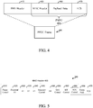
- FIG. 5 is a diagram illustrating an exemplary embodiment of a media access control (MAC) frame 500.
- the MAC frame 500 may comprise a media access control protocol data unit (MPDU) frame.
- MPDU media access control protocol data unit
- the MAC frame 500 may correspond to the payload portion 480, as previously described in connection with FIG. 4 .
- the MAC frame 500 includes 12 different fields: a frame control (fc) field 510, a duration/identification (dur) field 525, a receiver address (a1) field 530, a transmitter address (a2) field 535, a destination address (a3) field 540, a sequence control (sc) field 545, a fourth address (a4) field 550, a quality of service (QoS) control (qc) field 555, a high throughput (HT)/ very high throughput (VHT) control field 560, a frame body 568, and a frame check sequence (FCS) field 470.
- Some or all of the fields 510-565 may make up the MAC header 450 of FIG. 4 .
- a protocol version field of the frame control field 510 of the MAC frame 500 can be 0, or 1 or greater than 1.
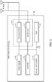
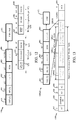
- FIG. 6 is a diagram illustrating an exemplary embodiment of a high efficiency (HE) control field 660.
- the top of FIG. 6 shows an exemplary format of high throughput (HT) control field 600.
- the HT control field may correspond to the HT/VHT control field 560 of FIG. 5 .
- the HT control field 600 comprises a very high throughput (VHT) field 601, a HT control middle field 602, an access category (AC) constraint field 603, and a reverse direction grant (RDG)/more physical layer convergence procedure protocol data unit (PPDU) field 604.
- VHT very high throughput
- AC access category
- RDG reverse direction grant
- PPDU physical layer convergence procedure protocol data unit
- Below the HT control field 600 is an expanded view of an exemplary format of the HT control middle field 602.
- the HT control middle field may comprise a link adaption control field 610, a calibration position field 611, a calibration sequence field 612, a first reserved field 613, a channel state information (CSI)/steering field 614, a HT null data packet (NDP) announcement field 615, a second reserved field 616, and a drop eligibility indicator (DEI) field 617.
- CSI channel state information
- NDP HT null data packet
- DEI drop eligibility indicator
- the VHT field 601 of the HT control field 600 is set to a value of 1 to indicate that HT control field 600 is configured in a VHT variant of the HT control field 600. As shown in FIG.
- the HT control field format 620 comprises the VHT field 601, a reserved field 621, a modulation and coding scheme (MCS) request (MRQ) field 622, a MCS request sequence identifier (MSI)/space-time block coding (STBC) field 623, a MCS feedback sequence identifier (MFSI)/a group identifier lowest bits (GID-L) field 624, a MCS feedback (MFB) field 625, a GID highest bits (GID-H) field 626, a coding type field 627, a feedback transmitter (Tx) type field 628, and an unsolicited MFB field 629.
- MCS modulation and coding scheme
- MRQ modulation and coding scheme
- MCS MCS request sequence identifier
- STBC space-time block coding
- MCSI MCS feedback sequence identifier
- GID-L group identifier lowest bits
- MCS feedback (MFB) field 625 a GID highest bits
- the VHT field 601 of the HT control field 600 is set to a value of 1 and a second field or bit is set to 1 to indicate that the HE control field 660 is configured as a HE variant of the VHT variant of the HT control field 600.
- the HE control field 660 comprises a HE indicator field 661, a control identifier (ID) field 662, an end of HE control (EOH) field 663, and a control information field 664.
- HE indicator field 661 comprises the second field discussed above or the reserved field 621 of FIG.
- the HT control field 600 is configured as the HE variant of the VHT variant of the HT control field 600.
- the HE indicator field 661 is set to 0 then the HT control field of the MAC frame 500 comprises the format of the HT control field 600. If the HE indicator field 661 is set to 1 then the HT control field of the MAC frame 500 comprises the HE control field 660.
- the control ID field 662 may comprise an indication of the content, type, and/or length of the information included in the control information field 664. In some embodiments, the control ID field 662 may comprise between 1-6 bits.
- the EOH field or end of control field 663 may store an indicator indicative of an end of a selected number of HE control fields 660 in the MAC frame (e.g., MAC frame 500 of FIG. 5 ) or a presence of another HE control field 660 in the MAC frame 500.
- the EOH field 663 may comprise between 1-6 bits.
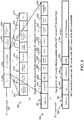
- FIG. 7A is a diagram of an exemplary MAC frame 700 comprising a HE control field 660 which comprises multiple HE control fields 660.
- FIG. 7A is similar to and adapted from MAC frame 500 of FIG. 5 . Only differences between the MAC frames 500 and 700 are described herein for the sake of brevity.
- HE control field 660 is located after the QoS control field 555 (if such field is present) may comprise a variable length depending on the number of HE control fields present and/or the type and/or amount of information included in the control information field 664 of each HE control field 660.
- the presence of the HE control field 660 may be indicated in an order field of a frame control (FC) field of a QoS MAC frame field 555 (i.e., a similar signaling that indicates the presence of an HT Control field).
- the length of the HE control field 660 and/or the control information field 664 of each HE control field 660 may be limited to multiples of two or four bytes.
- the HE control field 660 may comprise anywhere from 0 to n number of HE control fields 660, where n is an integer greater than or equal to 1.
- the HE control fields 660(1- n ) may be concatenated one after the other in a manner similar to that shown in FIG.
- MAC frame 700 also comprises counter mode (CTR) with cipher-block chaining message authentication code (CBC-MAC) protocol (CCMP) header field 765.
- CTR counter mode
- CBC-MAC cipher-block chaining message authentication code protocol
- the one or more HE Control fields precede the CCMP/GCMP header field or (if when this field is absent) they precede the payload (e.g., frame body 568) of the MAC frame (e.g., MAC frame 500, 700).
- the HE control field 660 in the MAC frame 700 includes that the HE control field 660 format may be backward compatible in that it is a flexible variant of the existing HT Control field 600, the HE control field 660 format may also be forward compatible in that it may be expansible for future amendments, as discussed herein, the HE control field 660 may reduce overhead by avoiding aggregation of multiple frames in A-MPDUs, the HE control field 660 may increase flexibility it that it may deliver a wide range of feedback information that can be used by the peer STAs or an AP to improve efficiency, as well as providing other benefits.
- the MAC frame 700 may comprise five (5) concatenated HE control fields 660, the EOH field 663 may be set to a 0 value in the first four (4) HE control fields to indicate the presence of another HE control field 660 and the EOH field 663 in the fifth or last HE control field 660 may be set to 1 to indicate that the fifth HE control field 660 is the end or last HE control field 660 in the MAC frame.
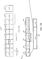
- FIG. 7B is a diagram of an exemplary short form MAC frame 799 comprising a HE aggregated control (HE A-control) field 795 which comprises multiple HE control fields 795.
- FIG. 7B is similar to and adapted from MAC frame 700 of FIG. 7 . Only differences between the MAC frames 700 and 799 are described herein for the sake of brevity.
- HE control field 795 is located after a service identifier (SID) field 790.
- the SID field 790 may comprise the A1 530 or A2 535 fields of FIG. 7A .
- FIG. 7B is a diagram of an exemplary short form MAC frame 799 comprising a HE aggregated control (HE A-control) field 795 which comprises multiple HE control fields 795.
- FIG. 7B is similar to and adapted from MAC frame 700 of FIG. 7 . Only differences between the MAC frames 700 and 799 are described herein for the sake of brevity.
- HE control field 795 is located after
- the HE control field 795 comprises a control ID field 797, a reserve field 798 and omits the VHT field 601 and HE field 661 of the HE control field 660 of FIG. 7A .
- the short form MAC frame 799 may have a smaller MAC overhead (e.g., 6-8 Bytes) than other MAC frames, which, in addition to aggregating HE Control fields (rather than aggregating MPDUs in A-MPDUs), reduces the MAC overhead.
- the first HE control field 795 of the multiple HE control fields 795 e.g., 795(1) shown in FIG.
- the HE control field 795 may correspond to the HE control field 795 having the lowest control ID value in the control ID field 797.
- subsequent HE control fields 795 may be ordered by non-decreasing values of the control ID field 797.
- the first HE control field 795 of the multiple HE control fields 795 e.g., 795(1) shown in FIG. 7B
- the subsequent HE control fields 795 may not be ordered based on the value of the control ID field 797.
- a padding field may follow the last HE control field 795 (e.g., 795(n)) of the aggregated HE control field 795.
- the padding field may be included such that the value of the aggregated HE control field 795 satisfies a certain length requirement (e.g., 30 bits) when carried in a HT control field (e.g., HT control field 600).
- an indication of the when the padding starts e.g., location of the padding field
- the indication may also include the padding contents (e.g., sequence of zeros, ones, or other value). In other aspects, there may be no indication and the padding may comprise a sequence of zeros. In some aspects, the padding may comprise a sequence of zeros and the start of padding may be determined by a device receiving the HE control field 795 by the occurrence of a sequence of zeros (with a maximum length corresponding to the size of the control ID value) following the end of an HE control field 795. In some aspects, the HE control field 795 is either the first and only HE control field 795 (and has a zero value in the control ID field 797), or is the last HE Control field 795 that has a non-zero value of the control ID field 797.
- the padding contents e.g., sequence of zeros, ones, or other value.
- the padding may comprise a sequence of zeros and the start of padding may be determined by a device receiving the HE control
- a bit in the Frame Control field 510 may indicate that the control wrapper format is redefined.
- any reserved field can be used for indicating the control wrapper format is redefined.
- the use of an order bit of the FC field 510 of any control frame may indicate the presence of the HE A-Control field 795 in the respective control frame.
- the short form MAC frame 799 may comprise a MAC header portion (not shown), the aggregated HE control field 795 and the FCS field 470.
- the MAC header portion comprises the FC field 510 and the SID field 790 shown in FIG. 7B .
- the short form MAC frame 799 may be referred to as an HE A-Control frame 799.
- the HE A-Control frame 799 may be defined as a new subtype of a control frame.
- the HE A-Control frame 799 may be carried in a multi-STA block acknowledgement (BA) frame.
- BA multi-STA block acknowledgement
- the use of the multi-STA BA frame to carry the HE A-Control frame 799 may be beneficial because it can be generated by both an AP and a non-AP STA. Additionally, the multi-STA BA frame may provide a unified way of signaling HE control information and can enable a STA to send the necessary HE control information whenever needed/requested and with no restrictions.
- the HE A-Control frame 799 may be carried in a trigger frame used to trigger MU-UL or MU-DL transmissions.
- FIG. 8A is a chart of exemplary values of the control ID field 662 and what those values indicate about the information in the control information field 664.
- column 801 illustrates various values for the control ID field 662
- column 802 illustrates various control information that will be included in the control information field 664 and an exemplary size of the control information field 664 in parenthesis
- column 803 illustrates various descriptions for the control information included in the control information field 664. For example, as illustrated in row 810 of FIG.
- a value of 0 in the control ID field 662 indicates a successful reception (RX) of a preceding MPDU frame and the control information field 664 may comprise acknowledgement (ACK) information and a value of 1 in the control ID field 662 indicates a failed reception of the preceding MPDU frame and the control information field 664 may comprise not acknowledgement (NACK) information.
- ACK/NACK acknowledgement/NACK in the HE control field 660 are that there may not be a need to aggregate ACK messages, which may reduce MAC overhead, and that the HE control field 660 may provide effective signaling for NACK messages.
- the values and descriptions provided in FIG. 8A are exemplary and other content and descriptions for different control ID field 662 values are possible.
- control ID field 662 may also indicate target wait time (TWT) related information, power control signaling, link adaptation information, operation mode changes (e.g., enabling RTS/CTS instruction, reducing or increasing BSS operation functionalities (baseline MCS/SS/BW, etc.)), energy detection information, performance metrics, coordination/scheduling information, basic service set (BSS) related signaling, etc.
- TWT target wait time
- power control signaling e.g., power control signaling
- link adaptation information e.g., link adaptation information, operation mode changes (e.g., enabling RTS/CTS instruction, reducing or increasing BSS operation functionalities (baseline MCS/SS/BW, etc.)
- operation mode changes e.g., enabling RTS/CTS instruction, reducing or increasing BSS operation functionalities (baseline MCS/SS/BW, etc.)
- energy detection information e.g., enabling RTS/CTS instruction, reducing or increasing BSS operation functionalities (baseline M
- FIG. 8B is a chart of other exemplary values of the control ID field 797 of FIG. 7B and what those values indicate about the information in the control information field 664.
- FIG. 9 is a diagram of the control information field 664 format when the control ID field 662 indicates BAR or BA information.
- the control ID field 662 value is 2, it indicates a BAR and the control information field 664 of HE control field 960 comprises a BAR control field 971 and a BAR information field 972.
- the control information field 664 of HE control field 960 comprises a BAR control field 971 and a BAR information field 972.
- control ID field 797 when the control ID field 797 is 2, it indicates a BAR and the control information field 664 of HE control field 960 comprises a BAR control field 971 and a BAR information field 972. While as shown in FIGs. 8A and 8B a value of 2 in the control ID fields 662 and 797 to indicate that the control ID fields 662 and 797 and the control information fields 664 includes information related BAR, other values in the control ID fields 662 and 797 are also possible to indicate BAR information.
- the BAR control field 971 comprises 2 bytes and the BAR information field 972 comprises a variable number of bytes.
- control ID field 662 value when the control ID field 662 value is 3, it indicates a BA which indicates a receive status of previously received MPDUs and the control information field 664 comprises a BA control field 981 and a BA information field 982.
- the BAR control field 981 comprises 2 bytes and the BAR information field 982 comprises a variable number of bytes.
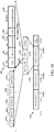
- FIG. 10 is a time sequence diagram showing an exemplary frame exchange 1000 in the wireless communication system 100.
- an AP and a STA1 may negotiate 2 downlink (DL) BA (with traffic identifiers TID 1, TID 2) and 1 uplink (UL) BA (with TID 3) sessions to occur within a transmission opportunity (TXOP) 1010.
- the AP requests a BA for TID 1 (e.g., a BAR1 included in a HE control field 1062) in an aggregated MPDU (A-MPDU) 1002 with TID 2.
- A-MPDU aggregated MPDU
- the STA1 responds with 2 BAs, BA1 for TID 1 (BAR1), and BA2 for TID2 (A-MPDU 1002) in an A-MPDU 1004 with TID 3.
- the A-MPDU 1004 comprises HE control field 1064 which includes BA1, BA2, and a cyclic redundancy check (CRC) for increasing protection.
- the AP transmits a BA3 1006. While as shown only HE control field 1064 includes a CRC, in some embodiments, the AP and/or the STA1 can add a CRC to the HE Control field for increasing protection.
- HE control fields shown in the exemplary frame exchange 1000 may reduce the MAC overhead within the TXOP 1010 by approximately 60 bytes. These bytes could be used to eliminate single point of failures induced by aggregating control frames. For example, HE control fields can be added to each MPDU and can be protected by an 8 bit CRC.
- CQI and MCS feedback information may comprise a variable number of bytes.
- the CQI and MCS feedback information may provide STAs communicating with each other information regarding the channel quality and/or MCS.
- a STA that is the intended receiver of a communication may want to signal to the transmitting STA/AP a preferred MCS rate or an update on a channel quality status so that the transmitting STA may make an appropriate selection of the MCS, channel, spatial streams, or other transmission parameters for transmission.
- control information field 664 is a diagram of the control information field 664 format of HE control field 1160 when the control ID field 662 indicates CQI or MCS feedback information.
- the control information field 664 comprises CQI control field 1171, a channel bitmap field 1172, a subchannel bitmap field 1173, and a channel/MCS feedback field 1174.
- the CQI control field 1171 may comprise 1 byte
- the channel bitmap field 1172 may comprise 1 byte
- the subchannel bitmap field 1173 may comprise 0 to 8 bytes
- the channel/MCS feedback field 1174 may comprise 0 to 3 times the number of spatial streams (N).
- the CQI control field 1171 may comprise a request/response field 1181, a dialog token field 1182, a subchannel bitmap present field 1183, channel/MCS indication field 1184, and a reserved field 1185.
- the channel/MCS feedback field 1174 may comprise two different formats depending on whether the control information field 664 is carrying CQI or MCS feedback information. As shown in FIG.
- the channel/MCS feedback field 1174 may comprise a number of spatial streams (NUM_STS) field 1191, a MCS field 1192, a guard interval (GI) field 1193, a multi-user (MU)/coding field 1194, a signal-to-noise ratio (SNR) field 1195, and a reserved field 1196.
- NUM_STS number of spatial streams
- MCS mobility control
- GI guard interval
- MU multi-user
- SNR signal-to-noise ratio
- reserved field 1196 a reserved field 1196.
- the channel/MCS feedback field 1174 may comprise a different set of fields which may include a SNR or receive signal strength indicator (RSSI) information.
- RSSI receive signal strength indicator
- the CQI/MCS feedback can be requested/provided by a STA for each channel and/or OFDMA subchannel as specified by the bitmaps (e.g., channel bitmap field 1172 and/or subchannel bitmap field 1173).
- the subchannel bitmap present field 1183 may indicate whether feedback should be provided/requested on a subchannel and the channel/MCS indication field 1184 may indicate whether the channel/MCS feedback field 1174 should contain MCS feedback or channel feedback as described above.
- a STA can provide to the requesting STA two types of feedback (parametrical or statistical). Parametrical feedback can indicate a recommended set of transmission parameters to be used by the requesting STA for transmissions to the STA.
- Statistical feedback may indicate a set of channel estimation metrics (e.g., SNR, RSSI, etc.) that allow the requesting STA to estimate the quality of the channels/subchannels at the STA.
- FIG. 12 is a diagram of the control information field 664 format when the control ID field 662 indicates an enhanced PS-poll (ePS-Poll) information.
- ePS-Poll enhanced PS-poll
- the ePS-Poll field 1270 comprises buffer status (BS) control field 1271 and a BS report field 1280.
- the BS control field 1271 comprises a request/response field 1272, an access category (AC) constraint field 1273, and a reserved field 1274.
- the BS report field 1280 comprises a scaling factor field 1281, a bufferable unit (BU) length field 1282 and a reserved field 1283.
- the scaling factor field 1281 may allow a STA to cover a wider range of BU length.
- the bufferable unit (BU) length indicates the size of BUs in octets while in certain other embodiments, this indicates the duration of time (e.g., in ⁇ s or scaled appropriately with the scaling factor) required to transmit the BUs.
- an AP may ask a STA to provide an UL BS report so that the AP knows and can allocate resources for an UL communication.
- the AC constraint field 1273 may indicate that BS request or response will be for each AC (AC constraint field 1273 is 1) or common for all ACs (AC constraint field 1273 is 0).
- of power-save signaling may be provided in the ePS-poll 1270.
- FIG. 13 is a diagram of the control information field 664 format when the control ID field 662 indicates CRC information. For example, in conjunction with FIG. 8A , when the control ID field 662 value is 31, it indicates the presence of CRC protection and the control information field 664 of HE control field 1360(d) comprises CRC field 1370.
- the CRC field 1370 may provide protection for all the preceding HE control fields of a MAC frame (e.g., MAC frame 1300 described below) or for all preceding fields contained in the MAC header of the MAC frame. In certain embodiments, the CRC field 1370 may always be present at the end of the HE control field 1360, hence, there may be no need for a control ID field to indicate the end of the HE control field.
- HE control field 1360(d) comprises a field of a MAC frame 1300.
- MAC frame 1300 is similar to and adapted from MAC frame 700 of FIG. 7A . Only differences between the MAC frames 700 and 1300 are described herein for the sake of brevity.
- MAC frame 1300 comprises multiple HE control fields 1360.
- MAC frame 1300 comprises HE control field 1360(a) which in some aspects corresponds to HE control field 960 of FIG. 9 , HE control field 1360(b) which in some aspects corresponds to HE control field 1160 of FIG. 11 , HE control field 1360(c) which in some aspects corresponds to HE control field 1260 of FIG.
- one or more of the multiple HE control fields 1360 may be addressed to one or more STAs.
- the HE control field 1360(a) may be addressed to a first STA and the HE control field 1360(b) may be addressed to a second STA.
- the number of HE control fields 1360 may be based on the number of STAs the DL MU PPDU is intended for. For example, if the DL MU PPDU is intended for four STAs, the PPDU may comprise four HE control fields 1360, one for each STA, although more or less HE control fields 1360 for each STA are also possible.
- a STA may add HE Control field 1360(d) containing a CRC field 1370 for protecting all preceding HE Control fields (e.g., Option 1 shown in FIG. 13 protecting HE Control fields 1360(a)-(d) of the MAC frame 1300).
- a non-limiting benefit for this embodiment is that it may allow separate error detection for control information signaling from the rest of the MAC frame 1300.
- a CRC pass indicates that control information has been received correctly independently of an FCS state.
- the CRC field 1370 protects all preceding fields contained in the MAC header of the MAC frame 1300 (e.g., Option 2 shown in FIG.
- the CRC protection in this embodiment may also whether the MAC frame 1300 is generated by a member STA or a non-member STA (e.g., for spatial reuse) or whether the MAC frame 1300 is intended for a particular STA, and if not, then correctly set a network allocation vector (NAV) (e.g., for TXOP protection and power save).
- NAV network allocation vector
- FIG. 14 is a diagram of the HE control information field 795 format when the control ID field 797 indicates a QoS information.
- the control ID field 662 value is 3, it indicates a buffer status request/report (i.e., an enhanced version of QoS Control) and the control information field 664 of HE control field 1460 comprises a QoS Control field 1470.
- the QoS Control field 1470 may comprise 2 bytes.
- the QoS Control field 1470 comprises a TID/SF field 1471 and a reserved field 1472 when conducting BS polling and comprises the TID/SF field 1471, a TXOP duration field 1475, and a queue size field 1476 when conducting a BS report.
- the AP may poll the STAs for their buffer status by sending BS polling frames that contain the QoS Control field 1470.
- the QoS Control field 1470 may specify whether polling is "per-TID", "all-TID", and other related BS polling parameters. In response, non-AP STAs may deliver BS reports in the QoS Control field 1470.
- per-TID BS information is carried in QoS Data and QoS Null frames.
- all-TID, per-TID BS information is carried in the QoS Control field 1470.
- the QoS Control field 1470 may be aggregated with other information in the HE control field 660.
- a non-limiting benefit of the QoS Control field 1470 is that it may reduce the MAC overhead incurred.
- FIG. 15 is a diagram of the HE control information field 795 format when the control ID field 797 indicates unicast trigger information.
- the control ID field 662 value is 5
- it indicates a trigger frame (i.e., an enhanced version of QoS Control)
- the control information field 664 of HE control field 1560 comprises a trigger information field 1570.
- the trigger information field 1570 may comprise a variable number of bytes.
- the trigger information field 1570 may comprise information regarding the trigger frame, subchannel allocation for a STA, a compressed/uncompressed UL MAC format, etc.
- the trigger information field 1570 may be aggregated with other information in the HE control field 660 and may be carried in a DL MU PPDU.
- a non-limiting benefit of the trigger information field 1570 is that it may reduce the MAC overhead incurred. For example, by being a part of a HE control field 660 in a DL MU PPDU, the additional control information regarding the trigger frame can be carried in a DL MU PPDU with minimal overhead.
- the HE control field 660 may be carried in a UL MU PPDU.
- the AP 110 may receive two or more PPDUs from two or more STAs.
- the UL MU PPDU may comprise one or more of the HE control fields 660 located in different parts of the UL MU PPDU as described herein (e.g., in the PHY header as part of a signal field (SIG-A, SIG-B or SIG-C).
- threes STAs may transmit information in a UL MU PPDU by transmitting three independent SIG-B fields 1700 (discussed below), one for each STA, each comprising one or more of the HE control fields 660.
- the SIG-B fields 1700 may be multiplexed in code, frequency or time by some other means (e.g., using CDMA, OFDMA, TDMA, SDMA, etc.). Additionally, for both DL and UL MU PPDUs, the PPDUs may be multiplexed in code, frequency or time by some other means to generate the MU PPDUs from and/or to multiple STAs.
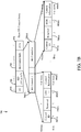
- FIG. 16 is a time sequence diagram showing an exemplary frame exchange 1600 in the wireless communication system 100.
- an AP may transmit a beacon message 1601 with traffic indication maps TIM 1, TIM 2, and TIM 4.
- the AP may then send a trigger message 1602 to request control information from the STAs for which it has DL BUs feedback.
- the AP may request QCI/MCS feedback and/or a BS report to adjust DL BU transmission parameters for each of the STAs.
- STAs (e.g., STA1, STA2, STA4) may report back by sending an enhanced PS-Poll frames 1603, 1604, and 1605, respectively.
- the ePS-Poll frames 1603, 1604, and 1605 may correspond to the ePS-Poll field 1270 of FIG. 12 and may include HE control responses for the requests in the trigger message 1602.
- the ePS-Poll frames 1603, 1604, and 1605 may include recommended DL resources (e.g., best M number of resources (in terms of channels, MCS, signal strength etc.)) and a BS report including the amount of data each STA has for UL to the AP.
- the AP Upon receiving this information the AP acknowledges receipt by sending ACK 1606 and schedules DL/UL transmissions for these STAs (e.g., using trigger message 1607 for scheduling DL 1 message 1608, DL 4 message 1609, UL 1 message 1610, and UL 4 message 1611 and using trigger message 1612 for scheduling DL 2 message 1613 and BA 2 message 1614).
- the AP may schedule the DL/UL transmissions using one of the recommended TX parameters from each STA and using the buffer status information received in the ePS-Poll frames 1603, 1604, and 1605 for an efficient allocation of network resources.
- a HE control field (e.g., HE control field 660) may be located in other parts of a PPDU frame. In some aspects, the HE control field 660 may be located in any field of a preamble portion of the PPDU.
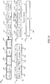
- FIG. 17A is a diagram of an exemplary 802.11 PPDU 1799.
- the PPDU 1799 may comprise a preamble portion 1750 and a data portion 1770.
- the preamble portion 1750 may comprise a legacy preamble portion 1755.
- the legacy preamble portion 1755 comprises contains a legacy short training field (L-STF) 1751, a long training field (L-LTF) 1752, and a signal field (L-SIG) field 1753.
- L-STF legacy short training field
- L-LTF long training field
- L-SIG signal field
- the preamble portion 1750 further comprises a repeated L-SIG field 1754, a HE-SIGA field 1760, a HE-SIGB field 1761, a HE-STF field 1762, a HE-LTF field 1763 and a HE-SIGC field 1764.
- the preamble portion 1750 can include additional fields (not shown), fields can be rearranged, removed, and/or resized, and the contents of the fields varied.
- the preamble portion 1750 can further include one or more of: a STF field (e.g., HT-STF, VHT-STF, HE-STF), a LTF field (e.g., HT-LTF, VHT-LTF, HE-LTF), one or more additional signal fields (e.g., additional HE-SIGA, HE-SIGB, HE-SIGC fields, HT-SIGA, VHT-SIGB, VHT-SIGC, one or more repeated fields, etc.).
- a STF field e.g., HT-STF, VHT-STF, HE-STF
- LTF field e.g., HT-LTF, VHT-LTF, HE-LTF
- additional signal fields e.g., additional HE-SIGA, HE-SIGB, HE-SIGC fields, HT-SIGA, VHT-SIGB, VHT-SIGC, one or more
- that particular field, and the following fields may contain information for more than one STA if the PPDU is MU. Additionally, the information for more than one STA multiple users may be multiplexed in frequency, time, or code.
- FIG. 17B is a diagram of the HE control field 660 included in a SIG-B field 1700 of a physical layer (PHY) header of a PPDU (e.g., PPDU frame 400 or 1799).
- the SIG-B field 1700 is an HE SIG-B field of a HE PHY header as defined in an 802.11 standard.
- a bit (B1) of the SIG-B field 1700 is set to 0 then the content of the SIG-B field 1700 is whatever the PHY designs.
- a bit (B1) of the SIG-B field 1700 is set to 1 then the content of the SIG-B field 1700 is one or more HE control fields 660.
- the PPDU frame is a HE NDP carrying MAC information (CMAC) frame if a length of a L-SIG field indicates that it is a CMAC frame.
- CMAC MAC information
- a bit (B0) can be used as NDP indication (if 1 then NDP, otherwise a PLCP Service Data Unit (PSDU) is present).
- PSDU PLCP Service Data Unit
- a non-limiting benefit of including the HE control field in the SIG-B field is that it may provide a solution to move forward a trigger frame design because the HE Control field 660 can carry the contents of a trigger frame. Additionally, it may reduce the risk of having a parallel design for a PHY Trigger frame because the content of the HE Control field 660 to the PHY is provided by the MAC.
- the HE control field 660 may be located in any of the fields of the preamble portion 1750 of FIG. 17A (e.g., L-STF 1751, L-LTF 1752, L-SIG 1753, repeated L-SIG field 1754, HE-SIGA field 1760, HE-SIGB field 1761, HE-SIGC field 1764, etc.), including additional fields not shown. Additionally, one or more HE control fields 660 may be included in one or more of the preamble portion 1750 fields for one or more STAs receiving the PPDU 1799. For example, HE-SIGB 1761 may comprise one or more HE control fields 660 intended for one or more STAs and HE-SIGC 1764 may comprise one or more HE control fields 660 intended for one or more different STAs.
- the HE control field 660 may be located in an aggregated A-MPDU subframe.
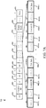
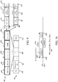
- FIG. 18 is a diagram of an A-MPDU 1800 which includes multiple A-MPDU subframes 1810.
- A-MPDU 1810(n) comprises a MPDU delimiter field 1820, a MPDU field 1830, and a padding field 1840.
- the MPDU delimiter field 1820 comprises an end of frame (EOF) field 1821, a reserved field 1822, a MPDU length field 1823, a CRC field 1824, and a delimiter signature field 1825.
- the MPDU field 1830 may comprise the HE control field 660.
- the contents of the HE control field 660 may be signaled in the A-MPDU subframe (e.g., A-MPDU subframe 1810(n)).
- the MPDU length field 1823 indicates a length of the MPDU is less than 14 Bytes then the MPDU 1830 may contain HE control field 660.
- the fact that a bit (B1) of the HE control field 660 is non-zero would be enough to determine the MPDU 1830 as a new format of the MPDU because the MPDU 1830 may resemble a PV2 frame.
- a non-limiting benefit of including the HE control field 660 in an A-MPDU subframe is that A-MPDU subframes containing HE control fields 660 can be used for padding the UL/DL MU PPDUs.
- At least one or more of the HE control fields 660 that are carried in a PPDU may contain an indication that the transmitter of the HE control fields 660 contained in the PPDU 1799 requests an acknowledgement for this portion of the PPDU 1799 (i.e., of the control information carried in HE control fields 660).
- the recipient may acknowledge such reception by sending an acknowledgement.
- the acknowledgement of correct reception of the HE control field 660 portion can be piggybacked in existing frames (e.g., Ack, BlockAck frames (as part of reserved fields or values therein) or can be a PPDU generated by the recipient that carries one or more HE control fields 660, at least one of which contains an indication of a successful (or unsuccessful) reception of a previously received HE control field 660 portion.
- a token field may be added in the HE control field 660 to identify the information/ack sequence.
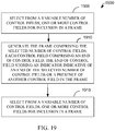
- FIG. 19 is a flow diagram of an exemplary method 1900 for wireless communication, in accordance with certain aspects of the present disclosure.
- Method 1900 may be performed by the device 302 in some aspects.
- the method 1900 may also be performed by one or more of the APs 110 or UTs 120 shown in FIGs. 1 and 2 , a person having ordinary skill in the art will appreciate that the method 1900 may be implemented by other suitable devices and systems.
- the method 1900 is described herein with reference to a particular order, in various embodiments, blocks herein may be performed in a different order, or omitted, and additional blocks may be added.
- Operation block 1905 includes selecting, from a variable number of control fields, one or more control fields for inclusion in a frame.
- Operation block 1910 includes generating the frame comprising the selected number of control fields, each control field comprising an end of control field, the end of control field storing an indicator indicative of an end of the selected number of control fields or a presence of another control field in the frame.
- Operation block 1915 includes transmitting the frame.
- an apparatus for wireless communication may perform one or more of the functions of method 1900, in accordance with certain embodiments described herein.
- the apparatus may comprise means for selecting, from a variable number of control fields, one or more control fields for inclusion in a frame.
- the means for selecting can be implemented by the processor 304 or DSP 320 ( FIG. 3 ).
- the means for generating can be configured to perform the functions of block 1905 ( FIG. 19 ).
- the apparatus may further comprise means for generating the frame comprising the selected number of control fields, each control field comprising an end of control field, the end of control field storing an indicator indicative of an end of the selected number of control fields or a presence of another control field in the frame.
- the means for generating can be implemented by the processor 304 or DSP 320 ( FIG. 3 ). In certain embodiments, the means for generating can be configured to perform the functions of block 1910 ( FIG. 19 ).
- the apparatus may further comprise means for transmitting the frame. In certain embodiments, the means for transmitting can be implemented by the transmitter 310 ( FIG. 3 ). In certain embodiments, the means for transmitting can be configured to perform the functions of block 1915 ( FIG. 19 ).
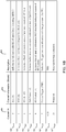
- FIG. 20 is a chart of other exemplary values of the control ID field 797 of FIG. 7B and what those values indicate about the information in the control information field 664.
- column 2001 illustrates various values for the control ID field 662
- column 2002 illustrates the meaning of the various control information that will be included in the control information field 664
- column 2003 illustrates various descriptions for the control information included in the control information field 664.
- a value of 0 in the control ID field 662 means an UL MU response scheduling and indicates the control information field 664 may contain scheduling information for an UL MU PPDU carrying immediate acknowledgement that is expected as a response to the soliciting A-MPDU.
- An example format of the control information field 664 when the control ID 662 is 0 is shown in Figure 21A .
- FIG. 21A shows a diagram of an exemplary format of the control information field 664 when the control ID field 662 is 0.
- the control information field 664 comprises a UL PPDU length field 2102, a resource unit (RU) allocation field 2104, and a third field 2106.
- the UL PPDU length field 2102 may indicate the length of the UL MU response.
- the UL PPDU length field 2102 comprises between 9 - 12 bits.
- the UL PPDU length field 2102 may contain the 9-12 (the actual value depends on the size of the UL PPDU length field) least significant bits (LSBs) of a length field in the L-SIG field of the PHY header of the frame that is to be sent as a response to the frame containing this control information.
- the receiving STA populates the 9-12 LSBs in the L-SIG field of the PHY header of the frame it transmits as a response using the contents of the UL PPDU length field 2102 of the soliciting frame and sets the remaining 3-0 MSBs to 0.
- the UL PPDU length field 2102 contains the value in bytes, or in microseconds of the UL PPDU to be sent as a response.
- the UL PPDU length field 2102 may not be set to a zero value.
- the RU allocation field 2104 may indicate the resource unit (RU) assigned for transmitting the UL MU response. In some aspects, the RU allocation field 2104 may comprise between 1-15 bits. The third field may comprise between 1-15 bits and maybe reserved for future use.
- a value of 1 in the control ID field 662 means a receive operation mode indication and the control information field 664 may contain information related to the receive operation mode of the STA transmitting the MPDU containing the HE control field.
- An example format of the control information field 664 when the control ID 662 is 1 is shown in Figure 21B .
- FIG. 21B shows a diagram of an exemplary format of the control information field 664 when the control ID field 662 is 1.
- the control information field 664 comprises a receiver (RX) number of spatial streams (NSS) field 2152, a RX channel width field 2154, and a third field 2156.
- the RX NSS field 2152 may indicate the maximum number of spatial streams, N SS , supported by the STA in reception, and may be set to N SS - 1. In some aspects, the RX NSS field 2152 comprises 3 bits.
- the RX channel width field 2154 may indicate the operating channel width supported by the STA in reception.
- the RX channel width field 2154 is set to 0 for 20 MHz, 1 for 40 MHz, 2 for 80 MHz, and 3 for 160 MHz. In some aspects, the RX channel width field 2154 may comprise 2 bits.
- the third field 2156 may comprise between 0-X bits, where X is an integer greater than 1, and may be reserved for future use.
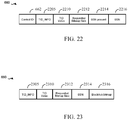
- FIG. 22 is a diagram of an exemplary control information field 664 format when the control ID field 662 indicates explicit ACK/BA request information.
- the control information field 664 of HE control field 660 comprises a TID_INFO field 2205, a TID value field 2210, a requested bitmap size field 2212, a starting sequence number (SSN) present field 2214, and a SSN field 2216.
- the TID_INFO field 2205 indicates the number of TIDs present in the HE control field 660 (e.g., TID_INFO value +1).
- the TID value field 2210 indicates the TID for which the requested Ack/BA is for.
- the requested bitmap size field 2212 indicates the requested (Block) Ack bitmap size (e.g., 0 if 1 bit (i.e., Ack/Nack), 1 if 1 Byte, 2 if 4 Bytes, 3 if 8 Bytes, etc.).
- the SSN present field 2214 indicates the presence of the SSN field 2216.
- the SSN present field 2214 may be set to 1 if the SSN subfield is present, otherwise it is set to 0.
- the SSN field 2216 contains the starting sequence number for this TID (A BAR). For example, its presence is an explicit indication for shifting the BA score.
- the TID_INFO field 2205 comprises 3 bits
- the TID value field 2210 comprises 4 bits
- the requested bitmap size field 2212 comprises 2 bits
- the SSN present field 2214 comprises 1 bit
- the SSN field 2216 comprises either 0 or 12 bits.
- control ID field 662 may indicate explicit ACK/BA response information and the control information field 664 may provide information related to immediate acknowledgement responses.
- the control information field 664 of HE control field 660 comprises a TID_INFO field 2305, a TID value field 2310, a requested bitmap size field 2312, a starting sequence number (SSN) field 2214, and a BA bitmap field 2316.
- the TID_INFO field 2305 indicates the number of TIDs present in the HE control field (e.g., HE control fields 795 of FIG. 7B ).
- the TID value field 2310 indicates the TID for which the Ack/BA response is for.
- the requested bitmap size field 2312 indicates the requested (Block) Ack bitmap size (e.g., 0 if 1 bit (i.e., Ack/Nack), 1 if 1 Byte, 2 if 4 Bytes, 3 if 8 Bytes, etc.).
- the SSN field 2314 contains the starting sequence number for the current TID (BA).
- the BA bitmap field 2316 includes a bitmap of values for BA. In some aspects, the BA bitmap field 2316 is present if the bitmap size is non-zero.
- the TID_INFO field 2305 comprises 3 bits
- the TID value field 2310 comprises 4 bits
- the requested bitmap size field 2312 comprises 2 bits
- the SSN field 2314 comprises either 0 or 12 bits
- the BA bitmap field 2316 comprises either 1, 16, 32, or 64 bits based on the value of the requested bitmap size field 2312.
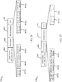
- FIG. 24 is a time sequence diagram 2400 illustrating exemplary frame exchanges comparing a baseline frame exchange (top portion) against a frame exchange utilizing explicit ACK/BA within an HE control field (bottom portion) (e.g., HE control fields 660 and 795).
- both the baseline and the ACK included in the BA frame show a VHT single MPDU 2401 transmitted from a first device.
- a second device in the baseline frame exchange transmits an acknowledgement (ACK) message 2402 followed by multiple MPDU messages 2405(a)-2405(n).
- the second device may transmit the MPDUs 2410(a)-2410(n) to the first device.
- the MPDUs 2410(a)-2410(n) including the ACK within the HE control fields 660 and 795.
- FIG. 25 is a time sequence diagram 2500 illustrating exemplary frame exchanges comparing a baseline frame exchange (top portion) against a frame exchange utilizing explicit BAR within the HE control fields 660 and 795 (bottom portion).
- a first device transmits MPDUs 2421(a)-2421(n) followed by a BAR 2425.
- a second device in the baseline frame exchange transmits one or more BAs 2430 followed by one or more MPDUs 2435.
- a first device transmits MPDUs 2440(a)-2440(n) that include the BAR within the HE control fields 660 and 795 of the MPDUs.
- a second device in the bottom portion frame exchange transmits one or more BAs 2430 followed by one or more MPDUs 2435.
- Some non-limiting benefits of including BAR/BA information in one or more of the HE control fields 660 are that there may not be a need to aggregate BAR/BA messages or multiple control frames, which may reduce MAC overhead. Additionally, the inclusion of the BAR/BA information in the HE control fields is that it may eliminate a single point of failure since each MPDU may carry the BAR/BA information. In some aspects, the use of the HE control fields to carry the BAR/BA information may allow more flexibility as any MPDU can solicit responses for other MPDUs of other TIDs/types. Additionally, the use of multiple HE control fields 660 and 795 enables various combinations of control information that can be added seamlessly (e.g., as shown in FIG. 13 ). For example, one HE control field 660 may contain information for BAR and another HE control field 660 may contain information for channel quality information.
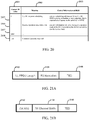
- FIG. 26 is a diagram of an exemplary format of a multi-STA block acknowledgement (BA) frame 2600, in accordance with an embodiment.
- the BA frame 2600 comprises a MAC Header portion 2602, a BA control field 2604, a BA information field 2610, and the FCS field 470.
- the MAC Header portion 2602 may comprise 2 bytes
- the BA control field 2604 may comprise 2 bytes
- the BA information field 2610 may comprise a variable number of bytes that contains information for each association identifier (AID) identified in the BA frame 2600.
- AID association identifier
- the BA information field 2610 may comprise one or more instances of a per-STA information subfield, one for each STA that is being addressed.
- Each per-STA information subfield includes the traffic identifier (TID) and the AID of the STA receiving the frame 2600.
- the per-STA information subfield may comprise a per-AID traffic identifier (TID) information field 2611, a block acknowledgement starting sequence control field 2612, and a BA bitmap field 2613. As shown in FIG.
- the BA frame 2600 contains information for "n" number of STAs and the per-STA information subfields contains per-AID TID information field 2611(1), the block acknowledgement starting sequence control field 2612(1), and the BA bitmap field 2613(1) through the fields 2611(n), 2612(n), and 2613(n) for the STAs 1-n.
- the per-AID TID information field 2611 enables ACK/BA for multiple TIDs contained in a multi-TID A-MPDU.
- the per-AID TID information field 2611 may also comprise an ACK type field (not shown) which may indicate a length of other fields in the BA information field 2610.
- the per-AID TID information field 2611 may comprise 2 bytes
- the block acknowledgement starting sequence control field 2612 may comprise 0 or 2 bytes
- the BA bitmap field 2613 may comprise 0, 4, 8, 32, or a variable number of bytes.
- the ACK type field may indicate the length for each of those fields.
- a certain value of the TID e.g., 15 or another value
- the multi-STA BA frame 2600 may be used by an AP as a response to a trigger-enabled PPDU.
- the BA frame 2600 can be sent in a legacy format, or aggregated in the response A-MPDU.
- the BA frame 2600 can be sent by a non-AP STA as a response to DL MU PPDUs and within the response A-MPDU.
- FIG. 27 is a diagram of an exemplary format of a multi-STA block acknowledgement (BA) frame 2700 which comprises the HE A-control field 795, in accordance with an embodiment.
- the BA frame 2700 is similar to and adapted from BA frame 2600 of FIG. 26 . Only differences between the BA frames 2600 and 2700 are described herein for the sake of brevity.
- BA frame 2700 comprises BA information field 2710 which includes the HE A-control field 795. While the HE A-control field 795 is shown at the end of the BA information field 2710, it may be located in an portion of the BA information field 2710 or may be associated with any AID or TID value.
- the HE A-control field 795 may comprises 4, 8 bytes or a variable number of bytes.
- a certain TID value may indicate the presence of the HE A-Control field 795.
- the per STA information subfield associated with this TID value may carry the HE A-Control field 795 rather than the BA starting sequence control field 2612 and/or the BA bitmap field 2613.
- the ACK type field of the per-AID TID information field 2611 may indicate the length of the HE A-Control field 795.
- the HE A-Control field 795 when the ACK type field is a first value, the HE A-Control field 795 is 4 bytes and when the ACK type field is a second value, the HE A-Control field 795 is 8 bytes or a variable number of bytes.
- an AP may send, as a response to one or more STAs, the multi-STA BA frame 2700 that contains BA information for one or more of its STAs and a HE A-control field 795 for one or more of its STAs.
- the BA information and the HE A-control field 795 could be for the same STAs or different STAs.
- the HE A-Control field 795 can also carry the UL MU resource allocation for the STAs.
- a STA may send as a response the multi-STA BA frame 2700 that contains both acknowledgement and feedback information.
- Embodiments described herein relating to the HE A-control frame 799 may beneficially help minimize MAC overhead because it may eliminate or reduce the need to aggregate multiple control frames in an A-MPDU. Additionally the HE A-control frame 799 may be legacy compliant (e.g., carried in a legacy PPDU format), all required control information is contained in the same control frame, and may enable combinations of control information to be added seamlessly (e.g., BA/Ack + Trigger, BA/Ack + Buffer Status, BA + CQI + ROMI, enhanced PS-Poll, etc.). Further, the HE A-control frame 799 may provide an efficient and flexible way of delivering HE control information which does not need control wrappers.
- legacy compliant e.g., carried in a legacy PPDU format
- all required control information is contained in the same control frame, and may enable combinations of control information to be added seamlessly (e.g., BA/Ack + Trigger, BA/Ack + Buffer Status, BA + CQI + ROMI,
- any reference to an element herein using a designation such as “first,” “second,” and so forth does not generally limit the quantity or order of those elements. Rather, these designations may be used herein as a convenient wireless device of distinguishing between two or more elements or instances of an element. Thus, a reference to first and second elements does not mean that only two elements may be employed there or that the first element must precede the second element in some manner. Also, unless stated otherwise a set of elements may include one or more elements.
- any of the various illustrative logical blocks, modules, processors, means, circuits, and algorithm steps described in connection with the aspects disclosed herein may be implemented as electronic hardware (e.g., a digital implementation, an analog implementation, or a combination of the two, which may be designed using source coding or some other technique), various forms of program or design code incorporating instructions (which may be referred to herein, for convenience, as "software” or a "software module), or combinations of both.
- software or a “software module”
- the various illustrative logical blocks, modules, and circuits described in connection with the aspects disclosed herein and in connection with FIGS. 1-7 may be implemented within or performed by an integrated circuit (IC), an access terminal, or an access point.
- the IC may include a general purpose processor, a digital signal processor (DSP), an application specific integrated circuit (ASIC), a field programmable gate array (FPGA) or other programmable logic device, discrete gate or transistor logic, discrete hardware components, electrical components, optical components, mechanical components, or any combination thereof designed to perform the functions described herein, and may execute codes or instructions that reside within the IC, outside of the IC, or both.
- the logical blocks, modules, and circuits may include antennas and/or transceivers to communicate with various components within the network or within the device.
- a general purpose processor may be a microprocessor, but in the alternative, the processor may be any conventional processor, controller, microcontroller, or state machine.
- a processor may also be implemented as a combination of computing devices, e.g., a combination of a DSP and a microprocessor, a plurality of microprocessors, one or more microprocessors in conjunction with a DSP core, or any other such configuration.
- the functionality of the modules may be implemented in some other manner as taught herein.
- the functionality described herein (e.g., with regard to one or more of the accompanying figures) may correspond in some aspects to similarly designated "means for" functionality in the appended claims.
- Computer-readable media includes both computer storage media and communication media including any medium that can be enabled to transfer a computer program from one place to another.
- a storage media may be any available media that may be accessed by a computer.
- such computer-readable media may include RAM, ROM, EEPROM, CD-ROM or other optical disk storage, magnetic disk storage or other magnetic storage devices, or any other medium that may be used to store desired program code in the form of instructions or data structures and that may be accessed by a computer.
- Disk and disc includes compact disc (CD), laser disc, optical disc, digital versatile disc (DVD), floppy disk, and blu-ray disc where disks usually reproduce data magnetically, while discs reproduce data optically with lasers. Combinations of the above should also be included within the scope of computer-readable media. Additionally, the operations of a method or algorithm may reside as one or any combination or set of codes and instructions on a machine readable medium and computer-readable medium, which may be incorporated into a computer program product.
Landscapes
- Engineering & Computer Science (AREA)
- Signal Processing (AREA)
- Computer Networks & Wireless Communication (AREA)
- Computer Security & Cryptography (AREA)
- Mobile Radio Communication Systems (AREA)
Description
- The present application relates generally to wireless communications, and more specifically to methods and devices for communicating control information.
- In many telecommunication systems, communications networks are used to exchange messages among several interacting spatially-separated devices. Networks may be classified according to geographic scope, which could be, for example, a metropolitan area, a local area, or a personal area. Such networks would be designated respectively as a wide area network (WAN), metropolitan area network (MAN), local area network (LAN), or personal area network (PAN). Networks also differ according to the switching/routing technique used to interconnect the various network nodes and devices (e.g. circuit switching vs. packet switching), the type of physical media employed for transmission (e.g. wired vs. wireless), and the set of communication protocols used (e.g. Internet protocol suite, SONET (Synchronous Optical Networking), Ethernet, etc.).
- Document
US 2014/307 612 A1 relates to systems, methods, and devices for wireless communication. One aspect of the disclosure provides a method of transmitting to two or more wireless communication devices. The method includes transmitting a first section of a preamble according to a first format, the first section of the preamble containing information informing devices compatible with the first format to defer to the transmission, transmitting a second section of the preamble according to a second format, the second section of the preamble containing tone allocation information, the tone allocation information identifying two or more wireless communication devices; and transmitting data to the two or more wireless communication devices simultaneously, the data contained on two or more sub-bands. - Wireless networks are often preferred when the network elements are mobile and thus have dynamic connectivity needs, or if the network architecture is formed in an ad hoc, rather than fixed, topology. Wireless networks employ intangible physical media in an unguided propagation mode using electromagnetic waves in the radio, microwave, infra-red, optical, etc. frequency bands. Wireless networks advantageously facilitate user mobility and rapid field deployment when compared to fixed wired networks.
- The devices in a wireless network may transmit/receive information between each other. The information may comprise packets, which in some aspects may be referred to as data units. In some aspects, devices may transmit control information in order to better facilitate communication between the devices. However, in some aspects, such information may increase overhead and reduce efficiency. Accordingly, there is a need for improved methods and devices for communicating such information between devices.
- The invention is defined in the independent claims. In the following, the parts of the description and drawings referring to embodiments which are not covered by the claims are not presented as embodiments of the invention but as background art or examples useful for understanding the invention.
- The systems, methods, devices, and computer program products discussed herein each have several aspects, no single one of which is solely responsible for its desirable attributes. Without limiting the scope of this invention as expressed by the claims which follow, some features are discussed briefly below. After considering this discussion, and particularly after reading the section entitled "Detailed Description," it will be understood how advantageous features of this invention allow for efficient use of the wireless communication medium.
- In one aspect, a method of wireless communication according to
claim 1 is disclosed. - In another aspect, a device for communicating in a wireless network according to
independent claim 14 is provided. - Another aspect of the present disclosure relates to a computer program according to
independent claim 15. -
-
FIG. 1 illustrates an example of a wireless communication system in which aspects of the present disclosure may be employed. -
FIG. 2 illustrates a block diagram of theaccess point 110 and two user terminals 120m and 120x in a MIMO system. -
FIG. 3 illustrates various components that may be utilized in a wireless device that may be employed within a wireless communication system. -
FIG. 4 shows a diagram of an exemplary physical layer convergence procedure (PLCP) protocol data unit (PPDU) frame. -
FIG. 5 shows a diagram of an medium access control (MAC) frame. -
FIG. 6 is a diagram illustrating an exemplary embodiment of a high efficiency (HE) control field. -
FIG. 7A is a diagram of an exemplary MAC frame comprising a HE control field which comprises multiple HE control fields. -
FIG. 7B is a diagram of another exemplary MAC frame comprising a HE control field which comprises multiple HE control fields. -
FIG. 8A is a chart of exemplary values of the control ID field of the HE control field. -
FIG. 8B is a chart of exemplary values of the control ID field of the short form HE control field. -
FIG. 9 is a diagram of a control information field format of the HE control field when the control ID field indicates block acknowledgement request (BAR) or block acknowledgement (BA) information. -
FIG. 10 is a time sequence diagram showing an exemplary frame exchange in thewireless communication system 100. -
FIG. 11 is a diagram of the control information field format of the HE control field when the control ID field indicates channel quality information (CQI) or modulation and coding scheme (MCS) feedback information. -
FIG. 12 is a diagram of the control information field format when the control ID field indicates an enhanced PS-poll (ePS-Poll) information. -
FIG. 13 is a diagram of the control information field format when the control ID field indicates CRC information. -
FIG. 14 is a diagram of the control information field format when the control ID field indicates quality of service (QoS) information. -
FIG. 15 is a diagram of the control information field format when the control ID field indicates trigger information. -
FIG. 16 is a time sequence diagram showing another exemplary frame exchange in thewireless communication system 100. -
FIG. 17A is a diagram of an exemplary PPDU format. -
FIG. 17B is a diagram of the HE control field included in a SIG-B field of a physical layer (PHY) header of a PPDU. -
FIG. 18 is a diagram of an A-MPDU which includes multiple A-MPDU subframes. -
FIG. 19 is a flow diagram of an exemplary method for wireless communication, in accordance with certain aspects of the present disclosure. -
FIG. 20 is a chart of other exemplary values of the control ID field and the control information field. -
FIG. 21A is a diagram of an exemplary format of the control information field, in accordance with an embodiment. -
FIG. 21B is a diagram of an exemplary format of the control information field, in accordance with an embodiment. -
FIG. 22 is a diagram of an exemplary format of the control ID field and the control information field, in accordance with an embodiment. -
FIG. 23 is a diagram of an exemplary format of the control information field, in accordance with an embodiment. -
FIG. 24 is an exemplary frame exchange between devices including an acknowledgement (ACK) message. -
FIG. 25 is an exemplary frame exchange between devices including an block acknowledgement request (BAR) message. -
FIG. 26 is a diagram of an exemplary format of a block acknowledgement (BA) frame, in accordance with an embodiment. -
FIG. 27 is a diagram of another exemplary format of a BA frame, in accordance with an embodiment. - Various aspects of the novel systems, apparatuses, and methods are described more fully hereinafter with reference to the accompanying drawings. The teachings disclosed may, however, be embodied in many different forms and should not be construed as limited to any specific structure or function presented throughout this disclosure. Rather, these aspects are provided so that this disclosure will be thorough and complete, and will fully convey the scope of the disclosure to those skilled in the art. Based on the teachings herein one skilled in the art should appreciate that the scope of the disclosure is intended to cover any aspect of the novel systems, apparatuses, and methods disclosed herein, whether implemented independently of or combined with any other aspect of the invention. For example, an apparatus may be implemented or a method may be practiced using any number of the aspects set forth herein. In addition, the scope of the invention is intended to cover such an apparatus or method which is practiced using other structure, functionality, or structure and functionality in addition to or other than the various aspects of the invention set forth herein. It should be understood that any aspect disclosed herein may be embodied by one or more elements of a claim.
- Although particular aspects are described herein, many variations and permutations of these aspects fall within the scope of the disclosure. Although some benefits and advantages of the preferred aspects are mentioned, the scope of the disclosure is not intended to be limited to particular benefits, uses, or objectives. Rather, aspects of the disclosure are intended to be broadly applicable to different wireless technologies, system configurations, networks, and transmission protocols, some of which are illustrated by way of example in the figures and in the following description of the preferred aspects. The detailed description and drawings are merely illustrative of the disclosure rather than limiting, the scope of the disclosure being defined by the appended claims.
- Wireless network technologies may include various types of wireless local area networks (WLANs). A WLAN may be used to interconnect nearby devices together, employing widely used networking protocols. The various aspects described herein may apply to any communication standard, such as WiFi or, more generally, any member of the IEEE 802.11 family of wireless protocols.
- In some aspects, wireless signals may be transmitted according to an 802.11 protocol using orthogonal frequency-division multiplexing (OFDM), direct-sequence spread spectrum (DSSS) communications, a combination of OFDM and DSSS communications, or other schemes.
- In some implementations, a WLAN includes various devices which are the components that access the wireless network. For example, there may be two types of devices: access points ("APs") and clients (also referred to as stations, commonly known as "STAs"). In general, an AP serves as a hub or base station for the WLAN and an STA serves as a user of the WLAN. For example, an STA may be a laptop computer, a personal digital assistant (PDA), a mobile phone, etc. In an example, an STA connects to an AP via a WiFi (e.g., IEEE 802.11 protocol) compliant wireless link to obtain general connectivity to the Internet or to other wide area networks. In some implementations an STA may also be used as an AP.
- An access point ("AP") may also comprise, be implemented as, or known as a NodeB, Radio Network Controller ("RNC"), eNodeB, Base Station Controller ("BSC"), Base Transceiver Station ("BTS"), Base Station ("BS"), Transceiver Function ("TF"), Radio Router, Radio Transceiver, or some other terminology.
- A station "STA" may also comprise, be implemented as, or known as an access terminal ("AT"), a subscriber station, a subscriber unit, a mobile station, a remote station, a remote terminal, a user terminal, a user agent, a user device, user equipment, or some other terminology. In some implementations an access terminal may comprise a cellular telephone, a cordless telephone, a Session Initiation Protocol ("SIP") phone, a wireless local loop ("WLL") station, a personal digital assistant ("PDA"), a handheld device having wireless connection capability, or some other suitable processing device connected to a wireless modem. Accordingly, one or more aspects taught herein may be incorporated into a phone (e.g., a cellular phone or smartphone), a computer (e.g., a laptop), a portable communication device, a headset, a portable computing device (e.g., a personal data assistant), an entertainment device (e.g., a music or video device, or a satellite radio), a gaming device or system, a global positioning system device, or any other suitable device that is configured to communicate via a wireless medium.
-
FIG. 1 is a diagram that illustrates a multiple-access multiple-input multiple-output (MIMO)system 100 with access points and user terminals. For simplicity, only oneaccess point 110 is shown inFIG. 1 . An access point is generally a fixed station that communicates with the user terminals and may also be referred to as a base station or using some other terminology. A user terminal or STA may be fixed or mobile and may also be referred to as a mobile station or a wireless device, or using some other terminology. Theaccess point 110 may communicate with one or more user terminals 120 at any given moment on the downlink and uplink. The downlink (i.e., forward link) is the communication link from the access point to the user terminals, and the uplink (i.e., reverse link) is the communication link from the user terminals to the access point. A user terminal may also communicate peer-to-peer with another user terminal. Asystem controller 130 couples to and provides coordination and control for the access points. - While portions of the following disclosure will describe user terminals 120 capable of communicating via Spatial Division Multiple Access (SDMA), for certain aspects, the user terminals 120 may also include some user terminals that do not support SDMA. Thus, for such aspects, the
AP 110 may be configured to communicate with both SDMA and non-SDMA user terminals. This approach may conveniently allow older versions of user terminals ("legacy" stations) that do not support SDMA to remain deployed in an enterprise, extending their useful lifetime, while allowing newer SDMA user terminals to be introduced as deemed appropriate. - The
system 100 employs multiple transmit and multiple receive antennas for data transmission on the downlink and uplink. Theaccess point 110 is equipped with N ap antennas and represents the multiple-input (MI) for downlink transmissions and the multiple-output (MO) for uplink transmissions. A set of K selected user terminals 120 collectively represents the multiple-output for downlink transmissions and the multiple-input for uplink transmissions. For pure SDMA, it is desired to have N ap ≤ K ≤ 1 if the data symbol streams for the K user terminals are not multiplexed in code, frequency or time by some means. K may be greater than N ap if the data symbol streams can be multiplexed using TDMA technique, different code channels with CDMA, disjoint sets of sub-bands with OFDM, and so on. Each selected user terminal may transmit user-specific data to and/or receive user-specific data from the access point. In general, each selected user terminal may be equipped with one or multiple antennas (i.e., N ut ≥ 1). The K selected user terminals can have the same number of antennas, or one or more user terminals may have a different number of antennas. - The
SDMA system 100 may be a time division duplex (TDD) system or a frequency division duplex (FDD) system. For a TDD system, the downlink and uplink share the same frequency band. For an FDD system, the downlink and uplink use different frequency bands. TheMIMO system 100 may also utilize a single carrier or multiple carriers for transmission. Each user terminal may be equipped with a single antenna (e.g., in order to keep costs down) or multiple antennas (e.g., where the additional cost can be supported). Thesystem 100 may also be a TDMA system if the user terminals 120 share the same frequency channel by dividing transmission/reception into different time slots, where each time slot may be assigned to a different user terminal 120. -
FIG. 2 illustrates a block diagram of theaccess point 110 and two user terminals 120m and 120x inMIMO system 100. Theaccess point 110 is equipped withNt antennas 224a through 224ap. The user terminal 120m is equipped with Nut,m antennas 252ma through 252mu, and the user terminal 120x is equipped with Nut,x antennas 252xa through 252xu. Theaccess point 110 is a transmitting entity for the downlink and a receiving entity for the uplink. The user terminal 120 is a transmitting entity for the uplink and a receiving entity for the downlink. As used herein, a "transmitting entity" is an independently operated apparatus or device capable of transmitting data via a wireless channel, and a "receiving entity" is an independently operated apparatus or device capable of receiving data via a wireless channel. In the following description, the subscript "dn" denotes the downlink, the subscript "up" denotes the uplink, Nup user terminals are selected for simultaneous transmission on the uplink, and Ndn user terminals are selected for simultaneous transmission on the downlink. Nup may or may not be equal to Ndn, and Nup and Ndn may be static values or may change for each scheduling interval. Beam-steering or some other spatial processing technique may be used at theaccess point 110 and/or the user terminal 120. - On the uplink, at each user terminal 120 selected for uplink transmission, a TX data processor 288 receives traffic data from a data source 286 and control data from a controller 280. The TX data processor 288 processes (e.g., encodes, interleaves, and modulates) the traffic data for the user terminal based on the coding and modulation schemes associated with the rate selected for the user terminal and provides a data symbol stream. A TX spatial processor 290 performs spatial processing on the data symbol stream and provides Nut,m transmit symbol streams for the Nut,m antennas. Each transmitter unit (TMTR) 254 receives and processes (e.g., converts to analog, amplifies, filters, and frequency upconverts) a respective transmit symbol stream to generate an uplink signal. Nut,m transmitter units 254 provide Nut,m uplink signals for transmission from Nut,m antennas 252, for example to transmit to the
access point 110. - Nup user terminals may be scheduled for simultaneous transmission on the uplink. Each of these user terminals may perform spatial processing on its respective data symbol stream and transmit its respective set of transmit symbol streams on the uplink to the
access point 110. - At the
access point 110, Nup antennas 224a through 224ap receive the uplink signals from all Nup user terminals transmitting on the uplink. Each antenna 224 provides a received signal to a respective receiver unit (RCVR) 222. Each receiver unit 222 performs processing complementary to that performed by transmitter unit 254 and provides a received symbol stream. An RXspatial processor 240 performs receiver spatial processing on the Nup received symbol streams from Nup receiver units 222 and provides Nup recovered uplink data symbol streams. The receiver spatial processing may be performed in accordance with the channel correlation matrix inversion (CCMI), minimum mean square error (MMSE), soft interference cancellation (SIC), or some other technique. Each recovered uplink data symbol stream is an estimate of a data symbol stream transmitted by a respective user terminal. AnRX data processor 242 processes (e.g., demodulates, deinterleaves, and decodes) each recovered uplink data symbol stream in accordance with the rate used for that stream to obtain decoded data. The decoded data for each user terminal may be provided to adata sink 244 for storage and/or acontroller 230 for further processing. - On the downlink, at the
access point 110, aTX data processor 210 receives traffic data from adata source 208 for Ndn user terminals scheduled for downlink transmission, control data from acontroller 230, and possibly other data from ascheduler 234. The various types of data may be sent on different transport channels.TX data processor 210 processes (e.g., encodes, interleaves, and modulates) the traffic data for each user terminal based on the rate selected for that user terminal. TheTX data processor 210 provides Ndn downlink data symbol streams for the Ndn user terminals. A TXspatial processor 220 performs spatial processing (such as a precoding or beamforming) on the Ndn downlink data symbol streams, and provides Nup transmit symbol streams for the Nup antennas. Each transmitter unit 222 receives and processes a respective transmit symbol stream to generate a downlink signal. Nup transmitter units 222 may provide Nup downlink signals for transmission from Nup antennas 224, for example to transmit to the user terminals 120. - At each user terminal 120, Nut,m antennas 252 receive the Nup downlink signals from the
access point 110. Each receiver unit 254 processes a received signal from an associated antenna 252 and provides a received symbol stream. An RX spatial processor 260 performs receiver spatial processing on Nut,m received symbol streams from Nut,m receiver units 254 and provides a recovered downlink data symbol stream for the user terminal 120. The receiver spatial processing may be performed in accordance with the CCMI, MMSE, or some other technique. An RX data processor 270 processes (e.g., demodulates, deinterleaves and decodes) the recovered downlink data symbol stream to obtain decoded data for the user terminal. - At each user terminal 120, a channel estimator 278 estimates the downlink channel response and provides downlink channel estimates, which may include channel gain estimates, SNR estimates, noise variance and so on. Similarly, a
channel estimator 228 estimates the uplink channel response and provides uplink channel estimates. Controller 280 for each user terminal typically derives the spatial filter matrix for the user terminal based on the downlink channel response matrix Hdn,m for that user terminal.Controller 230 derives the spatial filter matrix for the access point based on the effective uplink channel response matrix Hup,eff. The controller 280 for each user terminal may send feedback information (e.g., the downlink and/or uplink eigenvectors, eigenvalues, SNR estimates, and so on) to theaccess point 110. Thecontrollers 230 and 280 may also control the operation of various processing units at theaccess point 110 and user terminal 120, respectively. -
FIG. 3 illustrates various components that may be utilized in awireless device 302 that may be employed within thewireless communication system 100. Thewireless device 302 is an example of a device that may be configured to implement the various methods described herein. Thewireless device 302 may implement anaccess point 110 or a user terminal 120. - The
wireless device 302 may include aprocessor 304 which controls operation of thewireless device 302. Theprocessor 304 may also be referred to as a central processing unit (CPU).Memory 306, which may include both read-only memory (ROM) and random access memory (RAM), provides instructions and data to theprocessor 304. A portion of thememory 306 may also include non-volatile random access memory (NVRAM). Theprocessor 304 may perform logical and arithmetic operations based on program instructions stored within thememory 306. The instructions in thememory 306 may be executable to implement the methods described herein. - The
processor 304 may comprise or be a component of a processing system implemented with one or more processors. The one or more processors may be implemented with any combination of general-purpose microprocessors, microcontrollers, digital signal processors (DSPs), field programmable gate array (FPGAs), programmable logic devices (PLDs), controllers, state machines, gated logic, discrete hardware components, dedicated hardware finite state machines, or any other suitable entities that can perform calculations or other manipulations of information. - The processing system may also include machine-readable media for storing software. Software shall be construed broadly to mean any type of instructions, whether referred to as software, firmware, middleware, microcode, hardware description language, or otherwise. Instructions may include code (e.g., in source code format, binary code format, executable code format, or any other suitable format of code). The instructions, when executed by the one or more processors, cause the processing system to perform the various functions described herein.
- The
wireless device 302 may also include ahousing 308 that may include atransmitter 310 and areceiver 312 to allow transmission and reception of data between thewireless device 302 and a remote location. Thetransmitter 310 andreceiver 312 may be combined into atransceiver 314. A single or a plurality of transceiver antennas 316 may be attached to thehousing 308 and electrically coupled to thetransceiver 314. Thewireless device 302 may also include (not shown) multiple transmitters, multiple receivers, and multiple transceivers. - The
wireless device 302 may also include asignal detector 318 that may be used in an effort to detect and quantify the level of signals received by thetransceiver 314. Thesignal detector 318 may detect such signals as total energy, energy per subcarrier per symbol, power spectral density and other signals. Thewireless device 302 may also include a digital signal processor (DSP) 320 for use in processing signals. - The various components of the
wireless device 302 may be coupled together by abus system 322, which may include a power bus, a control signal bus, and a status signal bus in addition to a data bus. - In some aspects, a wide range of control information may be exchanged between STAs and/or APs using an 802.11 protocol. For example, STAs may exchange buffer status (BS) feedback, channel quality information feedback, resource allocation, power save (PS) feedback, etc. in order to facilitate more efficient communication between wireless devices. This control information may be required to be signaled somewhere within exchanged frames between the STAs and/or APs. In some aspects, including this information in various containers (e.g., frames, element, fields) may add to design complexity. Additionally, including this control information in an aggregation of multiple types of frames (e.g., control, management, data, etc.) may increase medium access control (MAC) MAC overhead. Accordingly, it may be beneficial to define a new type of control field in a MAC frame in order to better exchange such control information. In such a new type of control field, the control field may comprise one or more control fields carrying a variety of control information in one or more MAC frames. In addition, the new type of control field may indicate the end of the one or more control frames and may be generated to include a variable amount of information in each control field.
-
FIG. 4 is a diagram illustrating an exemplary embodiment of a physical layer convergence procedure (PLCP) protocol data unit (PPDU)frame 400. As shown inFIG. 4 , thePPDU frame 400 comprises a physical layer (PHY)header 415 and a PLCP service data unit (PSDU) 480 comprising aMAC header field 450, apayload data field 460, and a frame check sequence (FCS)field 470. ThePSDU 480 may also be referred to as apayload portion 480 of thePPDU 400. ThePHY header 415 may be used to acquire an incoming OFDM signal, to train and synchronize a demodulator, and may aid in demodulation and delivery of thepayload portion 480. -
FIG. 5 is a diagram illustrating an exemplary embodiment of a media access control (MAC)frame 500. In some embodiments, theMAC frame 500 may comprise a media access control protocol data unit (MPDU) frame. In some embodiments, theMAC frame 500 may correspond to thepayload portion 480, as previously described in connection withFIG. 4 . As shown, theMAC frame 500 includes 12 different fields: a frame control (fc)field 510, a duration/identification (dur)field 525, a receiver address (a1)field 530, a transmitter address (a2)field 535, a destination address (a3)field 540, a sequence control (sc)field 545, a fourth address (a4)field 550, a quality of service (QoS) control (qc)field 555, a high throughput (HT)/ very high throughput (VHT)control field 560, aframe body 568, and a frame check sequence (FCS)field 470. Some or all of the fields 510-565 may make up theMAC header 450 ofFIG. 4 . In some embodiments, a protocol version field of theframe control field 510 of theMAC frame 500 can be 0, or 1 or greater than 1. -
FIG. 6 is a diagram illustrating an exemplary embodiment of a high efficiency (HE)control field 660. The top ofFIG. 6 shows an exemplary format of high throughput (HT)control field 600. In some embodiments, the HT control field may correspond to the HT/VHT control field 560 ofFIG. 5 . As shown inFIG. 6 , theHT control field 600 comprises a very high throughput (VHT)field 601, a HT controlmiddle field 602, an access category (AC) constraint field 603, and a reverse direction grant (RDG)/more physical layer convergence procedure protocol data unit (PPDU)field 604. Below theHT control field 600, is an expanded view of an exemplary format of the HT controlmiddle field 602. In some aspects, the HT control middle field may comprise a linkadaption control field 610, acalibration position field 611, acalibration sequence field 612, a firstreserved field 613, a channel state information (CSI)/steering field 614, a HT null data packet (NDP)announcement field 615, a secondreserved field 616, and a drop eligibility indicator (DEI)field 617. - Below the expanded HT control
middle field 602 inFIG. 6 , is a second expanded view of a secondexemplary format 620 of the HT controlmiddle field 602. In this embodiment, theVHT field 601 of theHT control field 600 is set to a value of 1 to indicate thatHT control field 600 is configured in a VHT variant of theHT control field 600. As shown inFIG. 6 , the HTcontrol field format 620 comprises theVHT field 601, areserved field 621, a modulation and coding scheme (MCS) request (MRQ) field 622, a MCS request sequence identifier (MSI)/space-time block coding (STBC)field 623, a MCS feedback sequence identifier (MFSI)/a group identifier lowest bits (GID-L) field 624, a MCS feedback (MFB) field 625, a GID highest bits (GID-H) field 626, acoding type field 627, a feedback transmitter (Tx)type field 628, and anunsolicited MFB field 629. - Below the second expanded HT control
middle field 620 inFIG. 6 , is an expanded view of an exemplary format of aHE control field 660. In this embodiment, theVHT field 601 of theHT control field 600 is set to a value of 1 and a second field or bit is set to 1 to indicate that theHE control field 660 is configured as a HE variant of the VHT variant of theHT control field 600. As shown inFIG. 6 , theHE control field 660 comprises aHE indicator field 661, a control identifier (ID)field 662, an end of HE control (EOH)field 663, and acontrol information field 664. In some aspects,HE indicator field 661 comprises the second field discussed above or thereserved field 621 ofFIG. 6 and is indicative of whether theHT control field 600 is configured as the HE variant of the VHT variant of theHT control field 600. For example, in some embodiments, if theHE indicator field 661 is set to 0 then the HT control field of theMAC frame 500 comprises the format of theHT control field 600. If theHE indicator field 661 is set to 1 then the HT control field of theMAC frame 500 comprises theHE control field 660. Thecontrol ID field 662 may comprise an indication of the content, type, and/or length of the information included in thecontrol information field 664. In some embodiments, thecontrol ID field 662 may comprise between 1-6 bits. The EOH field or end ofcontrol field 663, may store an indicator indicative of an end of a selected number of HE controlfields 660 in the MAC frame (e.g.,MAC frame 500 ofFIG. 5 ) or a presence of anotherHE control field 660 in theMAC frame 500. In some embodiments, theEOH field 663 may comprise between 1-6 bits. - For example,
FIG. 7A is a diagram of anexemplary MAC frame 700 comprising aHE control field 660 which comprises multiple HE control fields 660.FIG. 7A is similar to and adapted fromMAC frame 500 ofFIG. 5 . Only differences between the MAC frames 500 and 700 are described herein for the sake of brevity. As shown inFIG. 7A , HE controlfield 660 is located after the QoS control field 555 (if such field is present) may comprise a variable length depending on the number of HE control fields present and/or the type and/or amount of information included in thecontrol information field 664 of each HE controlfield 660. In some aspects, the presence of theHE control field 660 may be indicated in an order field of a frame control (FC) field of a QoS MAC frame field 555 (i.e., a similar signaling that indicates the presence of an HT Control field). In some embodiments, the length of theHE control field 660 and/or thecontrol information field 664 of each HE controlfield 660 may be limited to multiples of two or four bytes. As further shown inFIG. 7A , theHE control field 660 may comprise anywhere from 0 to n number of HE controlfields 660, where n is an integer greater than or equal to 1. The HE control fields 660(1-n) may be concatenated one after the other in a manner similar to that shown inFIG. 7A . In some embodiments, theVHT field 601 and theHE indicator field 661 of the last n-1, HE controlfields 660 may re-used and/or re-purposed to carry other information or signaling as their values may only be required for the first HE Control field to differentiate this first field from the HT Control field and the VHT variant of the HT control field.MAC frame 700 also comprises counter mode (CTR) with cipher-block chaining message authentication code (CBC-MAC) protocol (CCMP)header field 765. In some embodiments the one or more HE Control fields precede the CCMP/GCMP header field or (if when this field is absent) they precede the payload (e.g., frame body 568) of the MAC frame (e.g.,MAC frame 500, 700). Some non-limiting benefits to theHE control field 660 in theMAC frame 700 include that theHE control field 660 format may be backward compatible in that it is a flexible variant of the existingHT Control field 600, theHE control field 660 format may also be forward compatible in that it may be expansible for future amendments, as discussed herein, theHE control field 660 may reduce overhead by avoiding aggregation of multiple frames in A-MPDUs, theHE control field 660 may increase flexibility it that it may deliver a wide range of feedback information that can be used by the peer STAs or an AP to improve efficiency, as well as providing other benefits. - In an exemplary embodiment, the
MAC frame 700 may comprise five (5) concatenated HE controlfields 660, theEOH field 663 may be set to a 0 value in the first four (4) HE control fields to indicate the presence of anotherHE control field 660 and theEOH field 663 in the fifth or lastHE control field 660 may be set to 1 to indicate that the fifthHE control field 660 is the end or lastHE control field 660 in the MAC frame. -
FIG. 7B is a diagram of an exemplary shortform MAC frame 799 comprising a HE aggregated control (HE A-control)field 795 which comprises multiple HE control fields 795.FIG. 7B is similar to and adapted fromMAC frame 700 ofFIG. 7 . Only differences between the MAC frames 700 and 799 are described herein for the sake of brevity. As shown inFIG. 7B , HE controlfield 795 is located after a service identifier (SID)field 790. TheSID field 790 may comprise theA1 530 orA2 535 fields ofFIG. 7A . As shown inFIG. 7B , theHE control field 795 comprises acontrol ID field 797, areserve field 798 and omits theVHT field 601 and HE field 661 of theHE control field 660 ofFIG. 7A . In some aspects, the shortform MAC frame 799 may have a smaller MAC overhead (e.g., 6-8 Bytes) than other MAC frames, which, in addition to aggregating HE Control fields (rather than aggregating MPDUs in A-MPDUs), reduces the MAC overhead. In some aspects, the firstHE control field 795 of the multiple HE control fields 795 (e.g., 795(1) shown inFIG. 7B ) may correspond to theHE control field 795 having the lowest control ID value in thecontrol ID field 797. In some embodiments, subsequentHE control fields 795 may be ordered by non-decreasing values of thecontrol ID field 797. In some aspects, the firstHE control field 795 of the multiple HE control fields 795 (e.g., 795(1) shown inFIG. 7B ) may correspond to theHE control field 795 with a control ID value in thecontrol ID field 797 equal to 0. In this embodiment, the subsequentHE control fields 795 may not be ordered based on the value of thecontrol ID field 797. - In some aspects, a padding field (not shown) may follow the last HE control field 795 (e.g., 795(n)) of the aggregated
HE control field 795. The padding field may be included such that the value of the aggregatedHE control field 795 satisfies a certain length requirement (e.g., 30 bits) when carried in a HT control field (e.g., HT control field 600). In some aspects, an indication of the when the padding starts (e.g., location of the padding field) may be included in a field of the aggregated HE control field 795 (e.g., thereserved field 798 orEOH field 663 of one or more of the HE control fields 795). In some aspects, the indication may also include the padding contents (e.g., sequence of zeros, ones, or other value). In other aspects, there may be no indication and the padding may comprise a sequence of zeros. In some aspects, the padding may comprise a sequence of zeros and the start of padding may be determined by a device receiving theHE control field 795 by the occurrence of a sequence of zeros (with a maximum length corresponding to the size of the control ID value) following the end of anHE control field 795. In some aspects, theHE control field 795 is either the first and only HE control field 795 (and has a zero value in the control ID field 797), or is the lastHE Control field 795 that has a non-zero value of thecontrol ID field 797. - In some aspects, a bit in the
Frame Control field 510 may indicate that the control wrapper format is redefined. For example, any reserved field can be used for indicating the control wrapper format is redefined. In other aspects, the use of an order bit of theFC field 510 of any control frame may indicate the presence of theHE A-Control field 795 in the respective control frame. - In some aspects, the short
form MAC frame 799 may comprise a MAC header portion (not shown), the aggregatedHE control field 795 and theFCS field 470. In some embodiments, the MAC header portion comprises theFC field 510 and theSID field 790 shown inFIG. 7B . In some aspects, the shortform MAC frame 799 may be referred to as an HEA-Control frame 799. In some embodiments, theHE A-Control frame 799 may be defined as a new subtype of a control frame. In other aspects, theHE A-Control frame 799 may be carried in a multi-STA block acknowledgement (BA) frame. The use of the multi-STA BA frame to carry theHE A-Control frame 799 may be beneficial because it can be generated by both an AP and a non-AP STA. Additionally, the multi-STA BA frame may provide a unified way of signaling HE control information and can enable a STA to send the necessary HE control information whenever needed/requested and with no restrictions. TheHE A-Control frame 799 may be carried in a trigger frame used to trigger MU-UL or MU-DL transmissions. - As discussed above, the content, type, and/or length of the information in the
control information field 664 may depend on the value of thecontrol ID field 662 itself or of a length field that may be added to theHE control field 660 itself.FIG. 8A is a chart of exemplary values of thecontrol ID field 662 and what those values indicate about the information in thecontrol information field 664. As shown inFIG. 8A ,column 801 illustrates various values for thecontrol ID field 662,column 802 illustrates various control information that will be included in thecontrol information field 664 and an exemplary size of thecontrol information field 664 in parenthesis, andcolumn 803 illustrates various descriptions for the control information included in thecontrol information field 664. For example, as illustrated inrow 810 ofFIG. 8A , a value of 0 in thecontrol ID field 662 indicates a successful reception (RX) of a preceding MPDU frame and thecontrol information field 664 may comprise acknowledgement (ACK) information and a value of 1 in thecontrol ID field 662 indicates a failed reception of the preceding MPDU frame and thecontrol information field 664 may comprise not acknowledgement (NACK) information. Some non-limiting benefits of including ACK/NACK in theHE control field 660 are that there may not be a need to aggregate ACK messages, which may reduce MAC overhead, and that theHE control field 660 may provide effective signaling for NACK messages. The values and descriptions provided inFIG. 8A are exemplary and other content and descriptions for differentcontrol ID field 662 values are possible. For example, thecontrol ID field 662 may also indicate target wait time (TWT) related information, power control signaling, link adaptation information, operation mode changes (e.g., enabling RTS/CTS instruction, reducing or increasing BSS operation functionalities (baseline MCS/SS/BW, etc.)), energy detection information, performance metrics, coordination/scheduling information, basic service set (BSS) related signaling, etc. -
FIG. 8B is a chart of other exemplary values of thecontrol ID field 797 ofFIG. 7B and what those values indicate about the information in thecontrol information field 664. - Another example of types of information indicated in the
control ID field rows FIG. 8A , include BAR information that may comprise 4 bytes and BA information that may comprise anywhere from 4 to 130 or more bytes.FIG. 9 is a diagram of thecontrol information field 664 format when thecontrol ID field 662 indicates BAR or BA information. For example, in conjunction withFIG. 8A , when thecontrol ID field 662 value is 2, it indicates a BAR and thecontrol information field 664 of HE controlfield 960 comprises aBAR control field 971 and aBAR information field 972. Similarly, in conjunction withFIGs. 7B and8B , when thecontrol ID field 797 is 2, it indicates a BAR and thecontrol information field 664 of HE controlfield 960 comprises aBAR control field 971 and aBAR information field 972. While as shown inFIGs. 8A and8B a value of 2 in the control ID fields 662 and 797 to indicate that the control ID fields 662 and 797 and the control information fields 664 includes information related BAR, other values in the control ID fields 662 and 797 are also possible to indicate BAR information. In some aspects, theBAR control field 971 comprises 2 bytes and theBAR information field 972 comprises a variable number of bytes. In another example, when thecontrol ID field 662 value is 3, it indicates a BA which indicates a receive status of previously received MPDUs and thecontrol information field 664 comprises aBA control field 981 and aBA information field 982. In some aspects, theBAR control field 981 comprises 2 bytes and theBAR information field 982 comprises a variable number of bytes. Some non-limiting benefits of including BAR/BA in theHE control field 660 are that there may not be a need to aggregate BAR/BA messages, which may reduce MAC overhead. -
FIG. 10 is a time sequence diagram showing an exemplary frame exchange 1000 in thewireless communication system 100. In the embodiment ofFIG. 10 , an AP and a STA1 may negotiate 2 downlink (DL) BA (withtraffic identifiers TID 1, TID 2) and 1 uplink (UL) BA (with TID 3) sessions to occur within a transmission opportunity (TXOP) 1010. The AP requests a BA for TID 1 (e.g., a BAR1 included in a HE control field 1062) in an aggregated MPDU (A-MPDU) 1002 withTID 2. As shown, the STA1 responds with 2 BAs, BA1 for TID 1 (BAR1), and BA2 for TID2 (A-MPDU 1002) in anA-MPDU 1004 withTID 3. TheA-MPDU 1004 comprises HE controlfield 1064 which includes BA1, BA2, and a cyclic redundancy check (CRC) for increasing protection. In response to theA-MPDU 1004 with TID3, the AP transmits aBA3 1006. While as shown only HE controlfield 1064 includes a CRC, in some embodiments, the AP and/or the STA1 can add a CRC to the HE Control field for increasing protection. The use of HE control fields shown in the exemplary frame exchange 1000 may reduce the MAC overhead within theTXOP 1010 by approximately 60 bytes. These bytes could be used to eliminate single point of failures induced by aggregating control frames. For example, HE control fields can be added to each MPDU and can be protected by an 8 bit CRC. - Another example of types of information indicated in the
control ID field row 813 ofFIG. 8A , include channel quality information (CQI) and MCS feedback information that may comprise a variable number of bytes. The CQI and MCS feedback information may provide STAs communicating with each other information regarding the channel quality and/or MCS. For example, a STA that is the intended receiver of a communication may want to signal to the transmitting STA/AP a preferred MCS rate or an update on a channel quality status so that the transmitting STA may make an appropriate selection of the MCS, channel, spatial streams, or other transmission parameters for transmission.FIG. 11 is a diagram of thecontrol information field 664 format ofHE control field 1160 when thecontrol ID field 662 indicates CQI or MCS feedback information. For example, in conjunction withFIG. 8A , when thecontrol ID field 662 value is 4, it indicates CQI or MCS feedback information and thecontrol information field 664 comprisesCQI control field 1171, achannel bitmap field 1172, asubchannel bitmap field 1173, and a channel/MCS feedback field 1174. In some embodiments, theCQI control field 1171 may comprise 1 byte, thechannel bitmap field 1172 may comprise 1 byte, thesubchannel bitmap field 1173 may comprise 0 to 8 bytes, and the channel/MCS feedback field 1174 may comprise 0 to 3 times the number of spatial streams (N). As shown inFIG. 11 , theCQI control field 1171 may comprise a request/response field 1181, a dialogtoken field 1182, a subchannel bitmappresent field 1183, channel/MCS indication field 1184, and areserved field 1185. The channel/MCS feedback field 1174 may comprise two different formats depending on whether thecontrol information field 664 is carrying CQI or MCS feedback information. As shown inFIG. 11 , when thecontrol information field 664 includes MCS feedback information, the channel/MCS feedback field 1174 may comprise a number of spatial streams (NUM_STS)field 1191, aMCS field 1192, a guard interval (GI) field 1193, a multi-user (MU)/coding field 1194, a signal-to-noise ratio (SNR)field 1195, and areserved field 1196. When thecontrol information field 664 includes channel feedback information, the channel/MCS feedback field 1174 may comprise a different set of fields which may include a SNR or receive signal strength indicator (RSSI) information. - In some embodiments, the CQI/MCS feedback can be requested/provided by a STA for each channel and/or OFDMA subchannel as specified by the bitmaps (e.g.,
channel bitmap field 1172 and/or subchannel bitmap field 1173). The subchannel bitmappresent field 1183 may indicate whether feedback should be provided/requested on a subchannel and the channel/MCS indication field 1184 may indicate whether the channel/MCS feedback field 1174 should contain MCS feedback or channel feedback as described above. A STA can provide to the requesting STA two types of feedback (parametrical or statistical). Parametrical feedback can indicate a recommended set of transmission parameters to be used by the requesting STA for transmissions to the STA. Statistical feedback may indicate a set of channel estimation metrics (e.g., SNR, RSSI, etc.) that allow the requesting STA to estimate the quality of the channels/subchannels at the STA. - Another type of information indicated in the
control ID field row 814 ofFIG. 8A , includes power-save poll (PS-poll) information. The PS-poll information may provide STAs communicating with each other information a power-save that includes UL buffer status report.FIG. 12 is a diagram of thecontrol information field 664 format when thecontrol ID field 662 indicates an enhanced PS-poll (ePS-Poll) information. For example, in conjunction withFIG. 8A , when thecontrol ID field 662 value is 5, it indicates an ePS-Poll which includes a UL buffer status report and thecontrol information field 664 ofHE control field 1260 comprises ePS-Poll field 1270. The ePS-Poll field 1270 comprises buffer status (BS)control field 1271 and aBS report field 1280. As shown below the ePS-Poll field 1270 inFIG. 12 , theBS control field 1271 comprises a request/response field 1272, an access category (AC)constraint field 1273, and areserved field 1274. TheBS report field 1280 comprises a scalingfactor field 1281, a bufferable unit (BU)length field 1282 and areserved field 1283. The scalingfactor field 1281 may allow a STA to cover a wider range of BU length. In certain embodiments, the bufferable unit (BU) length indicates the size of BUs in octets while in certain other embodiments, this indicates the duration of time (e.g., in µs or scaled appropriately with the scaling factor) required to transmit the BUs. - In some embodiments, an AP may ask a STA to provide an UL BS report so that the AP knows and can allocate resources for an UL communication. The
AC constraint field 1273 may indicate that BS request or response will be for each AC (AC constraint field 1273 is 1) or common for all ACs (AC constraint field 1273 is 0). In some aspects, of power-save signaling may be provided in the ePS-poll 1270. - Another type of information indicated in the
control ID field row 815 ofFIG. 8A , includes CRC-based protection information that may comprise 1 byte. The CRC information may provide CRC-based protection for the preceding fields of the MAC header for a MAC frame (e.g.,MAC frame 700 ofFIG. 7A ).FIG. 13 is a diagram of thecontrol information field 664 format when thecontrol ID field 662 indicates CRC information. For example, in conjunction withFIG. 8A , when thecontrol ID field 662 value is 31, it indicates the presence of CRC protection and thecontrol information field 664 of HE control field 1360(d) comprises CRC field 1370. The CRC field 1370 may provide protection for all the preceding HE control fields of a MAC frame (e.g.,MAC frame 1300 described below) or for all preceding fields contained in the MAC header of the MAC frame. In certain embodiments, the CRC field 1370 may always be present at the end of theHE control field 1360, hence, there may be no need for a control ID field to indicate the end of the HE control field. - As shown in
FIG. 13 , HE control field 1360(d) comprises a field of aMAC frame 1300.MAC frame 1300 is similar to and adapted fromMAC frame 700 ofFIG. 7A . Only differences between the MAC frames 700 and 1300 are described herein for the sake of brevity.MAC frame 1300 comprises multiple HE control fields 1360. As shown,MAC frame 1300 comprises HE control field 1360(a) which in some aspects corresponds to HE controlfield 960 ofFIG. 9 , HE control field 1360(b) which in some aspects corresponds to HE controlfield 1160 ofFIG. 11 , HE control field 1360(c) which in some aspects corresponds to HE controlfield 1260 ofFIG. 12 , the HE control field 1360(d), and may include other HE control fields (not shown). In some aspects, one or more of the multipleHE control fields 1360 may be addressed to one or more STAs. For example, in a DL MU PPDU, the HE control field 1360(a) may be addressed to a first STA and the HE control field 1360(b) may be addressed to a second STA. In some aspects, the number of HE controlfields 1360 may be based on the number of STAs the DL MU PPDU is intended for. For example, if the DL MU PPDU is intended for four STAs, the PPDU may comprise four HEcontrol fields 1360, one for each STA, although more or less HE controlfields 1360 for each STA are also possible. - In some embodiments, a STA may add HE Control field 1360(d) containing a CRC field 1370 for protecting all preceding HE Control fields (e.g.,
Option 1 shown inFIG. 13 protecting HE Control fields 1360(a)-(d) of the MAC frame 1300). A non-limiting benefit for this embodiment is that it may allow separate error detection for control information signaling from the rest of theMAC frame 1300. A CRC pass indicates that control information has been received correctly independently of an FCS state. In other embodiments, the CRC field 1370 protects all preceding fields contained in the MAC header of the MAC frame 1300 (e.g.,Option 2 shown inFIG. 13 protecting HE Control fields 1360(a)-(d) and all preceding fields up toFC field 510 of the MAC frame 1300). A non-limiting benefit for this embodiment is that it may allow for early detection of essential information. The CRC protection in this embodiment may also whether theMAC frame 1300 is generated by a member STA or a non-member STA (e.g., for spatial reuse) or whether theMAC frame 1300 is intended for a particular STA, and if not, then correctly set a network allocation vector (NAV) (e.g., for TXOP protection and power save). - Another type of information indicated in the
control ID field row 863 ofFIG. 8B , includes quality of service (QoS) information. The QoS information may provide STAs communicating with each other an indication of a buffer status request/report (i.e., an enhanced version of QoS Control).FIG. 14 is a diagram of the HE controlinformation field 795 format when thecontrol ID field 797 indicates a QoS information. For example, in conjunction withFIG. 8B , when thecontrol ID field 662 value is 3, it indicates a buffer status request/report (i.e., an enhanced version of QoS Control) and thecontrol information field 664 ofHE control field 1460 comprises aQoS Control field 1470. In some aspects, theQoS Control field 1470 may comprise 2 bytes. TheQoS Control field 1470 comprises a TID/SF field 1471 and areserved field 1472 when conducting BS polling and comprises the TID/SF field 1471, aTXOP duration field 1475, and aqueue size field 1476 when conducting a BS report. In some aspects, the AP may poll the STAs for their buffer status by sending BS polling frames that contain theQoS Control field 1470. TheQoS Control field 1470 may specify whether polling is "per-TID", "all-TID", and other related BS polling parameters. In response, non-AP STAs may deliver BS reports in theQoS Control field 1470. In some aspects, per-TID BS information is carried in QoS Data and QoS Null frames. In other aspects, all-TID, per-TID BS information is carried in theQoS Control field 1470. In some aspects, theQoS Control field 1470 may be aggregated with other information in theHE control field 660. A non-limiting benefit of theQoS Control field 1470 is that it may reduce the MAC overhead incurred. - Another type of information indicated in the
control ID field row 865 ofFIG. 8B , includes unicast trigger information. The unicast trigger information may provide STAs communicating with each other an indication of a trigger frame (resource allocation and other parameters for uplink).FIG. 15 is a diagram of the HE controlinformation field 795 format when thecontrol ID field 797 indicates unicast trigger information. For example, in conjunction withFIG. 8B , when thecontrol ID field 662 value is 5, it indicates a trigger frame (i.e., an enhanced version of QoS Control) and thecontrol information field 664 ofHE control field 1560 comprises atrigger information field 1570. In some aspects, thetrigger information field 1570 may comprise a variable number of bytes. Thetrigger information field 1570 may comprise information regarding the trigger frame, subchannel allocation for a STA, a compressed/uncompressed UL MAC format, etc. In some aspects, thetrigger information field 1570 may be aggregated with other information in theHE control field 660 and may be carried in a DL MU PPDU. A non-limiting benefit of thetrigger information field 1570 is that it may reduce the MAC overhead incurred. For example, by being a part of aHE control field 660 in a DL MU PPDU, the additional control information regarding the trigger frame can be carried in a DL MU PPDU with minimal overhead. - In some aspects, the
HE control field 660 may be carried in a UL MU PPDU. In an UL MU PPDU, theAP 110 may receive two or more PPDUs from two or more STAs. The UL MU PPDU may comprise one or more of theHE control fields 660 located in different parts of the UL MU PPDU as described herein (e.g., in the PHY header as part of a signal field (SIG-A, SIG-B or SIG-C). For example, threes STAs may transmit information in a UL MU PPDU by transmitting three independent SIG-B fields 1700 (discussed below), one for each STA, each comprising one or more of the HE control fields 660. In some embodiments, the SIG-B fields 1700 may be multiplexed in code, frequency or time by some other means (e.g., using CDMA, OFDMA, TDMA, SDMA, etc.). Additionally, for both DL and UL MU PPDUs, the PPDUs may be multiplexed in code, frequency or time by some other means to generate the MU PPDUs from and/or to multiple STAs. -
FIG. 16 is a time sequence diagram showing anexemplary frame exchange 1600 in thewireless communication system 100. In the embodiment ofFIG. 16 , an AP may transmit abeacon message 1601 with traffic indication mapsTIM 1,TIM 2, andTIM 4. The AP may then send atrigger message 1602 to request control information from the STAs for which it has DL BUs feedback. For example, the AP may request QCI/MCS feedback and/or a BS report to adjust DL BU transmission parameters for each of the STAs. STAs (e.g., STA1, STA2, STA4) may report back by sending an enhanced PS-Poll frames Poll frames Poll field 1270 ofFIG. 12 and may include HE control responses for the requests in thetrigger message 1602. The ePS-Poll frames ACK 1606 and schedules DL/UL transmissions for these STAs (e.g., usingtrigger message 1607 forscheduling DL 1message 1608,DL 4message 1609,UL 1message 1610, andUL 4message 1611 and usingtrigger message 1612 forscheduling DL 2message 1613 andBA 2 message 1614). The AP may schedule the DL/UL transmissions using one of the recommended TX parameters from each STA and using the buffer status information received in the ePS-Poll frames - In some embodiments, a HE control field (e.g., HE control field 660) may be located in other parts of a PPDU frame. In some aspects, the
HE control field 660 may be located in any field of a preamble portion of the PPDU.FIG. 17A is a diagram of an exemplary 802.11PPDU 1799. ThePPDU 1799 may comprise apreamble portion 1750 and adata portion 1770. Thepreamble portion 1750 may comprise alegacy preamble portion 1755. As shown, thelegacy preamble portion 1755 comprises contains a legacy short training field (L-STF) 1751, a long training field (L-LTF) 1752, and a signal field (L-SIG)field 1753. Thepreamble portion 1750 further comprises a repeated L-SIG field 1754, a HE-SIGA field 1760, a HE-SIGB field 1761, a HE-STF field 1762, a HE-LTF field 1763 and a HE-SIGC field 1764. In some aspects, thepreamble portion 1750 can include additional fields (not shown), fields can be rearranged, removed, and/or resized, and the contents of the fields varied. For example, in various embodiments, thepreamble portion 1750 can further include one or more of: a STF field (e.g., HT-STF, VHT-STF, HE-STF), a LTF field (e.g., HT-LTF, VHT-LTF, HE-LTF), one or more additional signal fields (e.g., additional HE-SIGA, HE-SIGB, HE-SIGC fields, HT-SIGA, VHT-SIGB, VHT-SIGC, one or more repeated fields, etc.). In some aspects, starting from a particular field of the PPDU 1799 (e.g., HE-SIGB 1761 in DL MU PPDU or from HE-STF 1762 in UL MU PPDU), that particular field, and the following fields, may contain information for more than one STA if the PPDU is MU. Additionally, the information for more than one STA multiple users may be multiplexed in frequency, time, or code. -
FIG. 17B is a diagram of theHE control field 660 included in a SIG-B field 1700 of a physical layer (PHY) header of a PPDU (e.g.,PPDU frame 400 or 1799). In some embodiments, the SIG-B field 1700 is an HE SIG-B field of a HE PHY header as defined in an 802.11 standard. In some aspects, when a bit (B1) of the SIG-B field 1700 is set to 0 then the content of the SIG-B field 1700 is whatever the PHY designs. In other aspects, when a bit (B1) of the SIG-B field 1700 is set to 1 then the content of the SIG-B field 1700 is one or more HE control fields 660. In some embodiments, the PPDU frame is a HE NDP carrying MAC information (CMAC) frame if a length of a L-SIG field indicates that it is a CMAC frame. In some aspects, a bit (B0) can be used as NDP indication (if 1 then NDP, otherwise a PLCP Service Data Unit (PSDU) is present). A non-limiting benefit of including the HE control field in the SIG-B field is that it may provide a solution to move forward a trigger frame design because theHE Control field 660 can carry the contents of a trigger frame. Additionally, it may reduce the risk of having a parallel design for a PHY Trigger frame because the content of theHE Control field 660 to the PHY is provided by the MAC. - As described above, the
HE control field 660 may be located in any of the fields of thepreamble portion 1750 ofFIG. 17A (e.g., L-STF 1751, L-LTF 1752, L-SIG 1753, repeated L-SIG field 1754, HE-SIGA field 1760, HE-SIGB field 1761, HE-SIGC field 1764, etc.), including additional fields not shown. Additionally, one or moreHE control fields 660 may be included in one or more of thepreamble portion 1750 fields for one or more STAs receiving thePPDU 1799. For example, HE-SIGB 1761 may comprise one or moreHE control fields 660 intended for one or more STAs and HE-SIGC 1764 may comprise one or moreHE control fields 660 intended for one or more different STAs. - In some embodiments, the
HE control field 660 may be located in an aggregated A-MPDU subframe. For example,FIG. 18 is a diagram of an A-MPDU 1800 which includes multipleA-MPDU subframes 1810. As shown, A-MPDU 1810(n) comprises aMPDU delimiter field 1820, aMPDU field 1830, and apadding field 1840. TheMPDU delimiter field 1820 comprises an end of frame (EOF)field 1821, areserved field 1822, aMPDU length field 1823, aCRC field 1824, and adelimiter signature field 1825. Additionally, theMPDU field 1830 may comprise theHE control field 660. In some embodiments, the contents of theHE control field 660 may be signaled in the A-MPDU subframe (e.g., A-MPDU subframe 1810(n)). For example, when theMPDU length field 1823 indicates a length of the MPDU is less than 14 Bytes then theMPDU 1830 may contain HE controlfield 660. In some aspects, the fact that a bit (B1) of theHE control field 660 is non-zero would be enough to determine theMPDU 1830 as a new format of the MPDU because theMPDU 1830 may resemble a PV2 frame. A non-limiting benefit of including theHE control field 660 in an A-MPDU subframe is that A-MPDU subframes containing HE controlfields 660 can be used for padding the UL/DL MU PPDUs. - In certain embodiments, at least one or more of the
HE control fields 660 that are carried in a PPDU (e.g., PPDU 1799) may contain an indication that the transmitter of the HE control fields 660 contained in thePPDU 1799 requests an acknowledgement for this portion of the PPDU 1799 (i.e., of the control information carried in HE control fields 660). Upon reception of thePPDU 1799 that contains a valid portion of the frame that carries theHE control fields 660, the recipient may acknowledge such reception by sending an acknowledgement. The acknowledgement of correct reception of theHE control field 660 portion can be piggybacked in existing frames (e.g., Ack, BlockAck frames (as part of reserved fields or values therein) or can be a PPDU generated by the recipient that carries one or moreHE control fields 660, at least one of which contains an indication of a successful (or unsuccessful) reception of a previously receivedHE control field 660 portion. In certain embodiments, to distinguish delivery/reception of multiple HE control fields 660 (sent over the air) a token field may be added in theHE control field 660 to identify the information/ack sequence. -
FIG. 19 is a flow diagram of anexemplary method 1900 for wireless communication, in accordance with certain aspects of the present disclosure.Method 1900 may be performed by thedevice 302 in some aspects. Themethod 1900 may also be performed by one or more of theAPs 110 or UTs 120 shown inFIGs. 1 and2 , a person having ordinary skill in the art will appreciate that themethod 1900 may be implemented by other suitable devices and systems. Although themethod 1900 is described herein with reference to a particular order, in various embodiments, blocks herein may be performed in a different order, or omitted, and additional blocks may be added. -
Operation block 1905 includes selecting, from a variable number of control fields, one or more control fields for inclusion in a frame.Operation block 1910 includes generating the frame comprising the selected number of control fields, each control field comprising an end of control field, the end of control field storing an indicator indicative of an end of the selected number of control fields or a presence of another control field in the frame.Operation block 1915 includes transmitting the frame. - In some embodiments, an apparatus for wireless communication may perform one or more of the functions of
method 1900, in accordance with certain embodiments described herein. The apparatus may comprise means for selecting, from a variable number of control fields, one or more control fields for inclusion in a frame. In certain embodiments, the means for selecting can be implemented by theprocessor 304 or DSP 320 (FIG. 3 ). In certain selecting, the means for generating can be configured to perform the functions of block 1905 (FIG. 19 ). The apparatus may further comprise means for generating the frame comprising the selected number of control fields, each control field comprising an end of control field, the end of control field storing an indicator indicative of an end of the selected number of control fields or a presence of another control field in the frame. In certain embodiments, the means for generating can be implemented by theprocessor 304 or DSP 320 (FIG. 3 ). In certain embodiments, the means for generating can be configured to perform the functions of block 1910 (FIG. 19 ). The apparatus may further comprise means for transmitting the frame. In certain embodiments, the means for transmitting can be implemented by the transmitter 310 (FIG. 3 ). In certain embodiments, the means for transmitting can be configured to perform the functions of block 1915 (FIG. 19 ). -
FIG. 20 is a chart of other exemplary values of thecontrol ID field 797 ofFIG. 7B and what those values indicate about the information in thecontrol information field 664. As shown inFIG. 20 ,column 2001 illustrates various values for thecontrol ID field 662,column 2002 illustrates the meaning of the various control information that will be included in thecontrol information field 664, andcolumn 2003 illustrates various descriptions for the control information included in thecontrol information field 664. For example, as illustrated inrow 2005 ofFIG. 20 , a value of 0 in thecontrol ID field 662 means an UL MU response scheduling and indicates thecontrol information field 664 may contain scheduling information for an UL MU PPDU carrying immediate acknowledgement that is expected as a response to the soliciting A-MPDU. An example format of thecontrol information field 664 when thecontrol ID 662 is 0 is shown inFigure 21A . -
FIG. 21A shows a diagram of an exemplary format of thecontrol information field 664 when thecontrol ID field 662 is 0. As shown, thecontrol information field 664 comprises a ULPPDU length field 2102, a resource unit (RU)allocation field 2104, and athird field 2106. The ULPPDU length field 2102 may indicate the length of the UL MU response. In some aspects, the ULPPDU length field 2102 comprises between 9 - 12 bits. In some aspects, the ULPPDU length field 2102 may contain the 9-12 (the actual value depends on the size of the UL PPDU length field) least significant bits (LSBs) of a length field in the L-SIG field of the PHY header of the frame that is to be sent as a response to the frame containing this control information. The receiving STA populates the 9-12 LSBs in the L-SIG field of the PHY header of the frame it transmits as a response using the contents of the ULPPDU length field 2102 of the soliciting frame and sets the remaining 3-0 MSBs to 0. Alternatively the ULPPDU length field 2102 contains the value in bytes, or in microseconds of the UL PPDU to be sent as a response. In some embodiments, the ULPPDU length field 2102 may not be set to a zero value. TheRU allocation field 2104 may indicate the resource unit (RU) assigned for transmitting the UL MU response. In some aspects, theRU allocation field 2104 may comprise between 1-15 bits. The third field may comprise between 1-15 bits and maybe reserved for future use. - Referring back to
FIG. 20 , inrow 2006, a value of 1 in thecontrol ID field 662 means a receive operation mode indication and thecontrol information field 664 may contain information related to the receive operation mode of the STA transmitting the MPDU containing the HE control field. An example format of thecontrol information field 664 when thecontrol ID 662 is 1 is shown inFigure 21B . -
FIG. 21B shows a diagram of an exemplary format of thecontrol information field 664 when thecontrol ID field 662 is 1. As shown, thecontrol information field 664 comprises a receiver (RX) number of spatial streams (NSS)field 2152, a RXchannel width field 2154, and athird field 2156. TheRX NSS field 2152 may indicate the maximum number of spatial streams, NSS , supported by the STA in reception, and may be set to NSS - 1. In some aspects, theRX NSS field 2152 comprises 3 bits. The RXchannel width field 2154 may indicate the operating channel width supported by the STA in reception. In some aspects, the RXchannel width field 2154 is set to 0 for 20 MHz, 1 for 40 MHz, 2 for 80 MHz, and 3 for 160 MHz. In some aspects, the RXchannel width field 2154 may comprise 2 bits. Thethird field 2156 may comprise between 0-X bits, where X is an integer greater than 1, and may be reserved for future use. - With reference to
FIGs. 6 and9 ,FIG. 22 is a diagram of an exemplarycontrol information field 664 format when thecontrol ID field 662 indicates explicit ACK/BA request information. For example, in some aspects, when thecontrol ID field 662 value is 3, it indicates explicit thatcontrol information field 664 provides information related to immediate ACK/BA request. As shown inFIG. 22 , thecontrol information field 664 of HE controlfield 660 comprises aTID_INFO field 2205, aTID value field 2210, a requestedbitmap size field 2212, a starting sequence number (SSN)present field 2214, and aSSN field 2216. In some aspects, theTID_INFO field 2205 indicates the number of TIDs present in the HE control field 660 (e.g., TID_INFO value +1). In some aspects, theTID value field 2210 indicates the TID for which the requested Ack/BA is for. In some aspects, the requestedbitmap size field 2212 indicates the requested (Block) Ack bitmap size (e.g., 0 if 1 bit (i.e., Ack/Nack), 1 if 1 Byte, 2 if 4 Bytes, 3 if 8 Bytes, etc.). In some aspects, the SSNpresent field 2214 indicates the presence of theSSN field 2216. For example the SSNpresent field 2214 may be set to 1 if the SSN subfield is present, otherwise it is set to 0. In some aspects, theSSN field 2216 contains the starting sequence number for this TID (A BAR). For example, its presence is an explicit indication for shifting the BA score. - In some aspects, the
TID_INFO field 2205 comprises 3 bits, theTID value field 2210 comprises 4 bits, the requestedbitmap size field 2212 comprises 2 bits, the SSNpresent field 2214 comprises 1 bit, and theSSN field 2216 comprises either 0 or 12 bits. - In another example, the
control ID field 662 may indicate explicit ACK/BA response information and thecontrol information field 664 may provide information related to immediate acknowledgement responses. For example, in some aspects, when thecontrol ID field 662 value is 4, it indicates explicit thatcontrol information field 664 provides information related to immediate acknowledgement responses. As shown inFIG. 23 , thecontrol information field 664 of HE controlfield 660 comprises aTID_INFO field 2305, aTID value field 2310, a requestedbitmap size field 2312, a starting sequence number (SSN)field 2214, and aBA bitmap field 2316. In some aspects, theTID_INFO field 2305 indicates the number of TIDs present in the HE control field (e.g., HE controlfields 795 ofFIG. 7B ). In some aspects, theTID value field 2310 indicates the TID for which the Ack/BA response is for. In some aspects, the requestedbitmap size field 2312 indicates the requested (Block) Ack bitmap size (e.g., 0 if 1 bit (i.e., Ack/Nack), 1 if 1 Byte, 2 if 4 Bytes, 3 if 8 Bytes, etc.). In some aspects, theSSN field 2314 contains the starting sequence number for the current TID (BA). In some aspects, theBA bitmap field 2316 includes a bitmap of values for BA. In some aspects, theBA bitmap field 2316 is present if the bitmap size is non-zero. - In some aspects, the
TID_INFO field 2305 comprises 3 bits, theTID value field 2310 comprises 4 bits, the requestedbitmap size field 2312 comprises 2 bits, theSSN field 2314 comprises either 0 or 12 bits, and theBA bitmap field 2316 comprises either 1, 16, 32, or 64 bits based on the value of the requestedbitmap size field 2312. -
FIG. 24 is a time sequence diagram 2400 illustrating exemplary frame exchanges comparing a baseline frame exchange (top portion) against a frame exchange utilizing explicit ACK/BA within an HE control field (bottom portion) (e.g., HE controlfields 660 and 795). As shown, inFIG. 24 , both the baseline and the ACK included in the BA frame show a VHTsingle MPDU 2401 transmitted from a first device. After a SIFS time period, a second device in the baseline frame exchange transmits an acknowledgement (ACK)message 2402 followed by multiple MPDU messages 2405(a)-2405(n). In the bottom portion, after the SIFS period, the second device may transmit the MPDUs 2410(a)-2410(n) to the first device. The MPDUs 2410(a)-2410(n) including the ACK within theHE control fields -
FIG. 25 is a time sequence diagram 2500 illustrating exemplary frame exchanges comparing a baseline frame exchange (top portion) against a frame exchange utilizing explicit BAR within theHE control fields 660 and 795 (bottom portion). As shown, inFIG. 25 , in the baseline top portion frame exchange, a first device transmits MPDUs 2421(a)-2421(n) followed by aBAR 2425. After a SIFS time period, a second device in the baseline frame exchange transmits one ormore BAs 2430 followed by one ormore MPDUs 2435. In the bottom portion, a first device transmits MPDUs 2440(a)-2440(n) that include the BAR within theHE control fields more BAs 2430 followed by one ormore MPDUs 2435. - Some non-limiting benefits of including BAR/BA information in one or more of the HE control fields 660 (or HE control
fields 795 ofFIG. 7B ) are that there may not be a need to aggregate BAR/BA messages or multiple control frames, which may reduce MAC overhead. Additionally, the inclusion of the BAR/BA information in the HE control fields is that it may eliminate a single point of failure since each MPDU may carry the BAR/BA information. In some aspects, the use of the HE control fields to carry the BAR/BA information may allow more flexibility as any MPDU can solicit responses for other MPDUs of other TIDs/types. Additionally, the use of multiple HE controlfields FIG. 13 ). For example, oneHE control field 660 may contain information for BAR and anotherHE control field 660 may contain information for channel quality information. -
FIG. 26 is a diagram of an exemplary format of a multi-STA block acknowledgement (BA)frame 2600, in accordance with an embodiment. As shown, theBA frame 2600 comprises aMAC Header portion 2602, aBA control field 2604, aBA information field 2610, and theFCS field 470. In some embodiments, theMAC Header portion 2602 may comprise 2 bytes, theBA control field 2604 may comprise 2 bytes, theBA information field 2610 may comprise a variable number of bytes that contains information for each association identifier (AID) identified in theBA frame 2600. - In some embodiments, the
BA information field 2610 may comprise one or more instances of a per-STA information subfield, one for each STA that is being addressed. Each per-STA information subfield includes the traffic identifier (TID) and the AID of the STA receiving theframe 2600. The per-STA information subfield may comprise a per-AID traffic identifier (TID)information field 2611, a block acknowledgement startingsequence control field 2612, and aBA bitmap field 2613. As shown inFIG. 26 , theBA frame 2600 contains information for "n" number of STAs and the per-STA information subfields contains per-AID TID information field 2611(1), the block acknowledgement starting sequence control field 2612(1), and the BA bitmap field 2613(1) through the fields 2611(n), 2612(n), and 2613(n) for the STAs 1-n. In some embodiments, the per-AIDTID information field 2611 enables ACK/BA for multiple TIDs contained in a multi-TID A-MPDU. The per-AIDTID information field 2611 may also comprise an ACK type field (not shown) which may indicate a length of other fields in theBA information field 2610. For example, the per-AIDTID information field 2611 may comprise 2 bytes, the block acknowledgement startingsequence control field 2612 may comprise 0 or 2 bytes, and theBA bitmap field 2613 may comprise 0, 4, 8, 32, or a variable number of bytes. The ACK type field may indicate the length for each of those fields. In some aspects, a certain value of the TID (e.g., 15 or another value) may indicate ACK for an action ACK carried in the A-MPDU. Themulti-STA BA frame 2600 may be used by an AP as a response to a trigger-enabled PPDU. In some aspects, theBA frame 2600 can be sent in a legacy format, or aggregated in the response A-MPDU. In some embodiments, theBA frame 2600 can be sent by a non-AP STA as a response to DL MU PPDUs and within the response A-MPDU. -
FIG. 27 is a diagram of an exemplary format of a multi-STA block acknowledgement (BA)frame 2700 which comprises theHE A-control field 795, in accordance with an embodiment. TheBA frame 2700 is similar to and adapted fromBA frame 2600 ofFIG. 26 . Only differences between the BA frames 2600 and 2700 are described herein for the sake of brevity. As shown inFIG. 27 ,BA frame 2700 comprisesBA information field 2710 which includes theHE A-control field 795. While theHE A-control field 795 is shown at the end of theBA information field 2710, it may be located in an portion of theBA information field 2710 or may be associated with any AID or TID value. In some aspects, theHE A-control field 795 may comprises 4, 8 bytes or a variable number of bytes. In some embodiments, a certain TID value may indicate the presence of theHE A-Control field 795. The per STA information subfield associated with this TID value may carry theHE A-Control field 795 rather than the BA startingsequence control field 2612 and/or theBA bitmap field 2613. In some aspects, the ACK type field of the per-AIDTID information field 2611 may indicate the length of theHE A-Control field 795. In some aspects, when the ACK type field is a first value, theHE A-Control field 795 is 4 bytes and when the ACK type field is a second value, theHE A-Control field 795 is 8 bytes or a variable number of bytes. - In some aspects, an AP may send, as a response to one or more STAs, the
multi-STA BA frame 2700 that contains BA information for one or more of its STAs and aHE A-control field 795 for one or more of its STAs. In some aspects, the BA information and theHE A-control field 795 could be for the same STAs or different STAs. TheHE A-Control field 795 can also carry the UL MU resource allocation for the STAs. In other embodiments, a STA may send as a response themulti-STA BA frame 2700 that contains both acknowledgement and feedback information. - Embodiments described herein relating to the
HE A-control frame 799 may beneficially help minimize MAC overhead because it may eliminate or reduce the need to aggregate multiple control frames in an A-MPDU. Additionally theHE A-control frame 799 may be legacy compliant (e.g., carried in a legacy PPDU format), all required control information is contained in the same control frame, and may enable combinations of control information to be added seamlessly (e.g., BA/Ack + Trigger, BA/Ack + Buffer Status, BA + CQI + ROMI, enhanced PS-Poll, etc.). Further, theHE A-control frame 799 may provide an efficient and flexible way of delivering HE control information which does not need control wrappers. - The word "exemplary" is used herein to mean "serving as an example, instance, or illustration." Any embodiment described herein as "exemplary" is not necessarily to be construed as preferred or advantageous over other embodiments. Various aspects of the novel systems, apparatuses, and methods are described more fully hereinafter with reference to the accompanying drawings. This disclosure may, however, be embodied in many different forms and should not be construed as limited to any specific structure or function presented throughout this disclosure. Rather, these aspects are provided so that this disclosure will be thorough and complete, and will fully convey the scope of the disclosure to those skilled in the art. Based on the teachings herein one skilled in the art should appreciate that the scope of the disclosure is intended to cover any aspect of the novel systems, apparatuses, and methods disclosed herein, whether implemented independently of, or combined with, any other aspect of the invention. For example, an apparatus may be implemented or a method may be practiced using any number of the aspects set forth herein. In addition, the scope of the invention is intended to cover such an apparatus or method which is practiced using other structure, functionality, or structure and functionality in addition to or other than the various aspects of the invention set forth herein. It should be understood that any aspect disclosed herein may be embodied by one or more elements of a claim.
- Although particular aspects are described herein, many variations and permutations of these aspects fall within the scope of the disclosure. Although some benefits and advantages of the preferred aspects are mentioned, the scope of the disclosure is not intended to be limited to particular benefits, uses, or objectives. Rather, aspects of the disclosure are intended to be broadly applicable to different wireless technologies, system configurations, networks, and transmission protocols, some of which are illustrated by way of example in the figures and in the following description of the preferred aspects. The detailed description and drawings are merely illustrative of the disclosure rather than limiting, the scope of the disclosure being defined by the appended claims.
- It should be understood that any reference to an element herein using a designation such as "first," "second," and so forth does not generally limit the quantity or order of those elements. Rather, these designations may be used herein as a convenient wireless device of distinguishing between two or more elements or instances of an element. Thus, a reference to first and second elements does not mean that only two elements may be employed there or that the first element must precede the second element in some manner. Also, unless stated otherwise a set of elements may include one or more elements.
- A person/one having ordinary skill in the art would understand that information and signals may be represented using any of a variety of different technologies and techniques. For example, data, instructions, commands, information, signals, bits, symbols, and chips that may be referenced throughout the above description may be represented by voltages, currents, electromagnetic waves, magnetic fields or particles, optical fields or particles, or any combination thereof.
- A person/one having ordinary skill in the art would further appreciate that any of the various illustrative logical blocks, modules, processors, means, circuits, and algorithm steps described in connection with the aspects disclosed herein may be implemented as electronic hardware (e.g., a digital implementation, an analog implementation, or a combination of the two, which may be designed using source coding or some other technique), various forms of program or design code incorporating instructions (which may be referred to herein, for convenience, as "software" or a "software module), or combinations of both. To clearly illustrate this interchangeability of hardware and software, various illustrative components, blocks, modules, circuits, and steps have been described above generally in terms of their functionality. Whether such functionality is implemented as hardware or software depends upon the particular application and design constraints imposed on the overall system. Skilled artisans may implement the described functionality in varying ways for each particular application, but such implementation decisions should not be interpreted as causing a departure from the scope of the present disclosure.
- The various illustrative logical blocks, modules, and circuits described in connection with the aspects disclosed herein and in connection with
FIGS. 1-7 may be implemented within or performed by an integrated circuit (IC), an access terminal, or an access point. The IC may include a general purpose processor, a digital signal processor (DSP), an application specific integrated circuit (ASIC), a field programmable gate array (FPGA) or other programmable logic device, discrete gate or transistor logic, discrete hardware components, electrical components, optical components, mechanical components, or any combination thereof designed to perform the functions described herein, and may execute codes or instructions that reside within the IC, outside of the IC, or both. The logical blocks, modules, and circuits may include antennas and/or transceivers to communicate with various components within the network or within the device. A general purpose processor may be a microprocessor, but in the alternative, the processor may be any conventional processor, controller, microcontroller, or state machine. A processor may also be implemented as a combination of computing devices, e.g., a combination of a DSP and a microprocessor, a plurality of microprocessors, one or more microprocessors in conjunction with a DSP core, or any other such configuration. The functionality of the modules may be implemented in some other manner as taught herein. The functionality described herein (e.g., with regard to one or more of the accompanying figures) may correspond in some aspects to similarly designated "means for" functionality in the appended claims. - If implemented in software, the functions may be stored on or transmitted over as one or more instructions or code on a computer-readable medium. The steps of a method or algorithm disclosed herein may be implemented in a processor-executable software module which may reside on a computer-readable medium. Computer-readable media includes both computer storage media and communication media including any medium that can be enabled to transfer a computer program from one place to another. A storage media may be any available media that may be accessed by a computer. By way of example, and not limitation, such computer-readable media may include RAM, ROM, EEPROM, CD-ROM or other optical disk storage, magnetic disk storage or other magnetic storage devices, or any other medium that may be used to store desired program code in the form of instructions or data structures and that may be accessed by a computer. Also, any connection can be properly termed a computer-readable medium. Disk and disc, as used herein, includes compact disc (CD), laser disc, optical disc, digital versatile disc (DVD), floppy disk, and blu-ray disc where disks usually reproduce data magnetically, while discs reproduce data optically with lasers. Combinations of the above should also be included within the scope of computer-readable media. Additionally, the operations of a method or algorithm may reside as one or any combination or set of codes and instructions on a machine readable medium and computer-readable medium, which may be incorporated into a computer program product.
- It is understood that any specific order or hierarchy of steps in any disclosed process is an example of a sample approach. Based upon design preferences, it is understood that the specific order or hierarchy of steps in the processes may be rearranged while remaining within the scope of the present disclosure. The accompanying method claims present elements of the various steps in a sample order, and are not meant to be limited to the specific order or hierarchy presented.
- Various modifications to the implementations described in this disclosure may be readily apparent to those skilled in the art, and the generic principles defined herein may be applied to other implementations without departing from the scope of this disclosure. Thus, the disclosure is not intended to be limited to the implementations shown herein, but is to be accorded the widest scope consistent with the claims, the principles and the novel features disclosed herein. The word "exemplary" is used exclusively herein to mean "serving as an example, instance, or illustration." Any implementation described herein as "exemplary" is not necessarily to be construed as preferred or advantageous over other implementations.
- Certain features that are described in this specification in the context of separate implementations also can be implemented in combination in a single implementation. Conversely, various features that are described in the context of a single implementation also can be implemented in multiple implementations separately or in any suitable sub-combination. Moreover, although features may be described above as acting in certain combinations and even initially claimed as such, one or more features from a claimed combination can in some cases be excised from the combination, and the claimed combination may be directed to a sub-combination or variation of a sub-combination.
- Similarly, while operations are depicted in the drawings in a particular order, this should not be understood as requiring that such operations be performed in the particular order shown or in sequential order, or that all illustrated operations be performed, to achieve desirable results. In certain circumstances, multitasking and parallel processing may be advantageous. Moreover, the separation of various system components in the implementations described above should not be understood as requiring such separation in all implementations, and it should be understood that the described program components and systems can generally be integrated together in a single software product or packaged into multiple software products. Additionally, other implementations are within the scope of the following claims. In some cases, the actions recited in the claims can be performed in a different order and still achieve desirable results.
Claims (15)
- A method (1900) of wireless communication, comprising:selecting (1905), from a variable number of control fields, one or more control fields for inclusion in a frame;generating (1910) the frame comprising the selected number of control fields; andtransmitting (1915) the frame, whereineach control field further comprises:a control identifier field (797); anda control information field (664), the control information field (664) including information for communication, the control identifier field (797) includingan indicator indicating a type of the information, whereinthe control identifier field indicates trigger information and wherein the control information field (664) comprises a trigger information field (1570), orwhereinthe control identifier field indicates a buffer status, BS, request or BS report (1609) and wherein the control information field (664) comprises one or more subfields containing a report on buffer status information or a request for buffer status information.
- The method (1900) of claim 1, wherein each control field further comprises a first field, the first field storing an indicator indicative of the control field comprising a variant of the control field, wherein the variant preferably comprises a high efficiency, HE, variant of a very high throughput, VHT, variant of the control field (660, 795).
- The method (1900) of claim 1, wherein the type of information comprises at least one of an acknowledgment, a not acknowledgement, a block acknowledgement request, a block acknowledgement, channel quality information, a modulation and coding scheme, MCS, feedback, a power save, PS, poll, and a cyclic redundancy check, wherein the control field indicates at least one of:a channel quality information and modulation and coding scheme, MCS, feedback and wherein the control information field (664) comprises a control field, a channel bitmap field, a subchannel field and a feedback field, wherein the content of the feedback field is based on the channel/MCS indication field, and wherein the feedback field comprises a number of spatial streams field, a MCS field, a multi-user/coding field, and a signal-to-noise ratio, SNR, field,a request/response field, a dialog token field, a subchannel bitmap present field, and a channel/MCS indication field,a power save poll field, anda cyclic redundancy check, CRC, and wherein the control information field (664) comprises a CRC field.
- The method (1900) of claim 1, wherein generating the frame comprises
generating the frame within a physical layer header portion of a physical layer convergence procedure, PLCP, protocol data unit, PPDU, frame (400), and wherein the physical layer header portion comprises one or more of a signal field, a long training field and a short training field, or
generating the frame within an aggregated media access control protocol data unit, A-MPDU, subframe (1800) containing the one or more control fields. - The method (1900) of claim 1, wherein the control information field (664) comprises a quality of service, QoS, control field (1470), and wherein the QoS control field comprises a traffic identifier, TID, field (2611) indicating whether BS polling is per-TID or all-TID, a transmission opportunity field, and a queue size field.
- The method (1900) of claim 1, wherein the trigger information field (1570) indicates subchannel information for a station or indicates a compressed or uncompressed uplink medium access control, MAC, format.
- The method (1900) of claim 1, wherein the selected number of control fields comprises one or more first control fields addressed to a first device and one or more second control fields addressed to a second device.
- The method (1900) of claim 1, wherein the one or more first control fields and the one or more second control fields are multiplexed in code, frequency, or time.
- The method (1900) of claim 1, wherein transmitting the frame (1915) comprises transmitting the frame using an uplink multiple user physical layer convergence procedure, PLCP, protocol data unit, PPDU, frame, or wherein transmitting the frame (1915) comprises transmitting the frame using a downlink multiple user physical layer convergence procedure, PLCP, protocol data unit, PPDU, frame.
- The method (1900) of claim 1, wherein the control identifier field indicates uplink, UL, multi-user, MU, response scheduling and wherein the control information field (664) includes scheduling information for transmitting an UL physical layer convergence procedure, PLCP, protocol data unit, PPDU, frame including acknowledgement information, wherein
the control information field (664) preferably comprises a UL PPDU length field (2102) indicating a length of the UL PPDU frame and a resource allocation field indicating a resource unit assigned for transmitting the UL PPDU frame. - The method (1900) of claim 1, wherein the frame further comprises a padding field (1840) that follows the one or more control fields so that a length of the one or more control fields satisfies a length requirement or a boundary requirement, wherein
the length requirement is preferably 30 bits and the boundary requirement is preferably a multiple of octets. - The method (1900) of claim 1, wherein the frame comprises
multiple-station block acknowledgement, BA, frame;
a trigger frame, or
a value of the AID field indicating the presence of one or more control fields following that value of the AID field, wherein the value of the AID field is preferably 2047. - The method (1900) of claim 1, wherein the frame further comprise a per association identifier, AID, traffic identifier, TID, information field, the per AID TID information field indicating a presence of the selected number of control fields, wherein the per AID TID information field preferably comprises
a type field indicating a number of bytes for the selected number of control fields, or
a value of the TID subfield indicating the presence of one or more control fields for the STA identified by the AID subfield of the per AID TID Information field. - A device (302) for communicating in a wireless network, the device comprising:means for selecting (1905), from a variable number of control fields, one or more control fields for inclusion in a frame;means for generating (1910) the frame comprising the selected number of control fields, each control field comprising an end of control field, the end of control field storing an indicator indicative of an end of the selected number of control fields or a presence of another control field in the frame; andmeans for transmitting (1915) the frame, whereineach control field further comprises:a control identifier field (797); anda control information field (664), the control information field (664) including information for communication, the control identifier field (797) includingan indicator indicating a type of the information, whereinthe control identifier field indicates trigger information and wherein the control information field (664) comprises a trigger information field (1570), or whereinthe control identifier field indicates a buffer status, BS, request or BS report (1609) and wherein the control information field (664) comprises one or more subfields containing a report on buffer status information or a request for buffer status information.
- A computer program product, comprising instructions which when executed by a processor, cause the processor to perform the method of any one of claims 1 to 13.
Applications Claiming Priority (9)
| Application Number | Priority Date | Filing Date | Title |
|---|---|---|---|
| US201562175620P | 2015-06-15 | 2015-06-15 | |
| US201562190220P | 2015-07-08 | 2015-07-08 | |
| US201562209184P | 2015-08-24 | 2015-08-24 | |
| US201562260176P | 2015-11-25 | 2015-11-25 | |
| US201562264153P | 2015-12-07 | 2015-12-07 | |
| US201662278342P | 2016-01-13 | 2016-01-13 | |
| US201662305978P | 2016-03-09 | 2016-03-09 | |
| US15/181,364 US10135957B2 (en) | 2015-06-15 | 2016-06-13 | Methods and apparatus for communicating high efficiency control information |
| PCT/US2016/037409 WO2016205220A2 (en) | 2015-06-15 | 2016-06-14 | Methods and apparatus for communicating high efficiency control information |
Publications (2)
| Publication Number | Publication Date |
|---|---|
| EP3308492A2 EP3308492A2 (en) | 2018-04-18 |
| EP3308492B1 true EP3308492B1 (en) | 2020-04-01 |
Family
ID=57517528
Family Applications (1)
| Application Number | Title | Priority Date | Filing Date |
|---|---|---|---|
| EP16732439.1A Active EP3308492B1 (en) | 2015-06-15 | 2016-06-14 | Methods and apparatus for communicating high efficiency control information |
Country Status (10)
| Country | Link |
|---|---|
| US (2) | US10135957B2 (en) |
| EP (1) | EP3308492B1 (en) |
| JP (1) | JP6783804B2 (en) |
| KR (1) | KR20180018549A (en) |
| CN (1) | CN107667497B (en) |
| CA (1) | CA2983868A1 (en) |
| ES (1) | ES2803656T3 (en) |
| HU (1) | HUE048919T2 (en) |
| TW (1) | TW201705712A (en) |
| WO (1) | WO2016205220A2 (en) |
Cited By (1)
| Publication number | Priority date | Publication date | Assignee | Title |
|---|---|---|---|---|
| US11792835B2 (en) | 2020-01-10 | 2023-10-17 | Samsung Electronics Co., Ltd. | Systems and methods for providing feedback for wireless communication |
Families Citing this family (36)
| Publication number | Priority date | Publication date | Assignee | Title |
|---|---|---|---|---|
| KR102262183B1 (en) * | 2014-04-04 | 2021-06-07 | 뉴라컴 인코포레이티드 | Acknowledgement method and multi user transmission method |
| US10306603B1 (en) | 2015-02-09 | 2019-05-28 | Marvell International Ltd. | Resource request for uplink multi-user transmission |
| US10135957B2 (en) | 2015-06-15 | 2018-11-20 | Qualcomm Incorporated | Methods and apparatus for communicating high efficiency control information |
| US10129001B2 (en) * | 2015-08-14 | 2018-11-13 | Newracom, Inc. | Block acknowledgment for multi-user transmissions in WLAN systems |
| WO2017030295A1 (en) | 2015-08-19 | 2017-02-23 | 엘지전자(주) | Method for feeding back channel state in wireless communication system and apparatus for same |
| US10512074B2 (en) * | 2015-08-31 | 2019-12-17 | Intel IP Corporation | Uplink (UL) multi-user (MU) feedback using high-efficiency (HE) long training fields in a wireless local-area network |
| US10728799B2 (en) * | 2015-10-23 | 2020-07-28 | Lg Electronics Inc. | Method for transmitting data in wireless communication system and device therefor |
| US10420121B2 (en) | 2015-11-03 | 2019-09-17 | Newracom, Inc. | Aggregated HE control content in A-MPDU |
| US10200147B2 (en) * | 2016-04-05 | 2019-02-05 | Intel IP Corporation | Sending feedback in a high efficiency service field |
| EP3443793A2 (en) * | 2016-04-12 | 2019-02-20 | Marvell World Trade Ltd. | Uplink multi-user transmission |
| US10574418B2 (en) | 2016-04-14 | 2020-02-25 | Marvell World Trade Ltd. | Determining channel availability for orthogonal frequency division multiple access operation |
| US10200514B2 (en) | 2016-06-29 | 2019-02-05 | Intel IP Corporation | Pre-high-efficiency (HE)-short training field preamble transmission for the HE-trigger based physical layer convergence protocol (PLCP) protocol data unit (PPDU) |
| US20180062805A1 (en) * | 2016-08-25 | 2018-03-01 | Po-Kai Huang | Setting of spatial reuse field for he trigger-based ppdu |
| WO2018066955A1 (en) * | 2016-10-04 | 2018-04-12 | 엘지전자 주식회사 | Method for transmitting or receiving frame in wireless lan system, and device therefor |
| US10959121B1 (en) * | 2016-12-20 | 2021-03-23 | Newracom, Inc. | Dynamic transmit chain availability signaling in wireless devices |
| WO2018174960A1 (en) * | 2017-03-24 | 2018-09-27 | Intel IP Corporation | Scaling factor for reporting quality of service queue size |
| US10686469B2 (en) * | 2017-05-15 | 2020-06-16 | Qualcomm Incorporated | Payload size ambiguity and false alarm rate reduction for polar codes |
| US10687321B2 (en) * | 2017-06-20 | 2020-06-16 | Mediatek Inc. | Network communication link adaptation systems and methods |
| CN116208460A (en) * | 2017-07-04 | 2023-06-02 | 华为技术有限公司 | Data processing method and device |
| CN109391393B (en) * | 2017-08-09 | 2021-05-14 | 华为技术有限公司 | Method and device for transmitting control information |
| US11057922B2 (en) * | 2017-12-20 | 2021-07-06 | Qualcomm Incorporated | Systems for communicating with unassociated stations |
| CN110138421B (en) * | 2018-02-08 | 2022-05-17 | 华为技术有限公司 | Channel detection method and related device |
| US10925092B2 (en) * | 2018-03-01 | 2021-02-16 | Apple Inc. | Request to send (RTS)/clear to send (CTS) using a self-contained slot |
| CN110380746B (en) | 2018-03-12 | 2021-08-31 | 苏州速通半导体科技有限公司 | Full-duplex communication method and station equipment in high-efficiency wireless local area network |
| WO2020009425A1 (en) * | 2018-07-03 | 2020-01-09 | 엘지전자 주식회사 | Method and device for identifying packet in wireless lan system |
| CN110730050A (en) * | 2018-07-17 | 2020-01-24 | 华为技术有限公司 | Communication method and device |
| MX2020001672A (en) | 2018-08-23 | 2020-07-13 | Lg Electronics Inc | Method and device for transmitting or receiving information on size of resource unit in wireless lan system. |
| US11337183B2 (en) * | 2019-02-28 | 2022-05-17 | Qualcomm Incorporated | Aggregated control information for a wireless communication network |
| CN112003682B (en) * | 2019-05-27 | 2023-05-12 | 华为技术有限公司 | Method and apparatus for retransmission |
| CN110190998B (en) * | 2019-06-03 | 2022-06-24 | 武汉思普崚技术有限公司 | Network situation visualization method and system |
| US11751090B2 (en) * | 2019-09-06 | 2023-09-05 | Qualcomm Incorporated | Reporting mechanisms for wireless communications |
| JP7416981B2 (en) * | 2020-05-18 | 2024-01-17 | エルジー エレクトロニクス インコーポレイティド | Trigger frame transmission in wireless communication system |
| CN113708888B (en) * | 2020-05-21 | 2023-03-03 | 华为技术有限公司 | Joint transmission method and device |
| CN114339875B (en) * | 2020-09-30 | 2024-04-12 | 华为技术有限公司 | Information transmission method and communication device |
| WO2022173218A1 (en) * | 2021-02-09 | 2022-08-18 | 엘지전자 주식회사 | Improved operation for constrained twt |
| US20230098549A1 (en) * | 2021-09-30 | 2023-03-30 | Huawei Technologies Co., Ltd. | Null data packet announcement (ndpa) frame indication |
Family Cites Families (26)
| Publication number | Priority date | Publication date | Assignee | Title |
|---|---|---|---|---|
| JP3967141B2 (en) * | 2002-01-28 | 2007-08-29 | 富士通株式会社 | Frame relay system and frame relay device |
| US20030198244A1 (en) * | 2002-04-23 | 2003-10-23 | Texas Instruments Incorporated | Group polling and reservation requests in a wireless network |
| KR20040098394A (en) * | 2003-05-14 | 2004-11-20 | 삼성전자주식회사 | Method for transmitting paging information to a mbms service in mobile communication system |
| KR100678264B1 (en) | 2004-02-06 | 2007-02-01 | 삼성전자주식회사 | Method for improving data processing speed in mobile communication system using high speed downlink packet access scheme and the mobile communication system |
| CN101548526B (en) | 2006-12-14 | 2016-07-06 | 艾利森电话股份有限公司 | Method and apparatus for alignment of protocol data units in a wireless communication system |
| EP3764718B1 (en) * | 2009-11-13 | 2022-11-02 | Interdigital Patent Holdings, Inc. | Method and apparatus for supporting management actions for very high throughput in wireless communications |
| EP3379739A1 (en) * | 2009-11-24 | 2018-09-26 | Electronics and Telecommunications Research Institute | Methods for transmitting a frame in a multi-user based wireless communication system |
| US9025428B2 (en) | 2010-04-14 | 2015-05-05 | Qualcomm Incorporated | Allocating and receiving tones for a frame |
| US9203586B2 (en) | 2011-06-15 | 2015-12-01 | Lg Electronics Inc. | Method for transmitting and receiving data unit based on uplink multiple user multiple input multiple output transmission and apparatus for the same |
| US9253808B2 (en) | 2011-07-10 | 2016-02-02 | Qualcomm Incorporated | Systems and methods for low-overhead wireless beacons having next full beacon indications |
| US9363707B2 (en) | 2011-12-29 | 2016-06-07 | Qualcomm Incorporated | Systems and methods for generating and decoding short control frames in wireless communications |
| US20130223338A1 (en) | 2012-02-29 | 2013-08-29 | Qualcomm Incorporated | Apparatus and methods for block acknowledgment compression |
| US9204287B2 (en) * | 2012-05-15 | 2015-12-01 | Futurewei Technologies, Inc. | System and method for reducing signaling overhead |
| US20130336182A1 (en) | 2012-06-13 | 2013-12-19 | Qualcomm Incorporated | Systems and methods for identifying enhanced frames for wireless communication |
| US9504032B2 (en) * | 2012-09-13 | 2016-11-22 | Interdigital Patent Holdings, Inc. | Method, wireless transmit/receive unit (WTRU) and base station for transferring small packets |
| EP3432502B1 (en) * | 2012-10-04 | 2019-12-04 | LG Electronics Inc. | Method and apparatus for transreceiving downlink signal by considering antenna port relationship in wireless communication system |
| JP6093030B2 (en) * | 2012-12-12 | 2017-03-08 | エルジー エレクトロニクス インコーポレイティド | Information transmission / reception method related to association identifier in wireless communication system and apparatus therefor |
| US10439773B2 (en) * | 2013-04-15 | 2019-10-08 | Qualcomm Incorporated | Systems and methods for backwards-compatible preamble formats for multiple access wireless communication |
| US9426261B2 (en) | 2013-05-15 | 2016-08-23 | Qualcomm Incorporated | Apparatus and methods for improved frames |
| US20150063190A1 (en) | 2013-08-28 | 2015-03-05 | Qualcomm Incorporated | Methods and apparatus for multiple user uplink |
| US20150110046A1 (en) | 2013-10-17 | 2015-04-23 | Qualcomm Incorporated | Methods and apparatus for channel state information feedback |
| US9544914B2 (en) | 2013-11-19 | 2017-01-10 | Intel IP Corporation | Master station and method for HEW communication using a transmission signaling structure for a HEW signal field |
| US20150327121A1 (en) * | 2014-05-08 | 2015-11-12 | Guoqing C. Li | Method, apparatus, and computer readable media for acknowledgement in wireless networks |
| US10693532B2 (en) * | 2014-09-03 | 2020-06-23 | Newracom, Inc. | Operation method of station in wireless local area network |
| US9699727B2 (en) * | 2014-11-04 | 2017-07-04 | Intel IP Corporation | Method, apparatus, and computer readable medium for signaling high efficiency preambles |
| US10135957B2 (en) | 2015-06-15 | 2018-11-20 | Qualcomm Incorporated | Methods and apparatus for communicating high efficiency control information |
-
2016
- 2016-06-13 US US15/181,364 patent/US10135957B2/en active Active
- 2016-06-14 JP JP2017564706A patent/JP6783804B2/en active Active
- 2016-06-14 EP EP16732439.1A patent/EP3308492B1/en active Active
- 2016-06-14 CN CN201680032131.5A patent/CN107667497B/en active Active
- 2016-06-14 CA CA2983868A patent/CA2983868A1/en not_active Abandoned
- 2016-06-14 ES ES16732439T patent/ES2803656T3/en active Active
- 2016-06-14 KR KR1020177035627A patent/KR20180018549A/en active Search and Examination
- 2016-06-14 WO PCT/US2016/037409 patent/WO2016205220A2/en active Application Filing
- 2016-06-14 HU HUE16732439A patent/HUE048919T2/en unknown
- 2016-06-15 TW TW105118808A patent/TW201705712A/en unknown
-
2018
- 2018-10-04 US US16/152,309 patent/US10812634B2/en active Active
Non-Patent Citations (1)
| Title |
|---|
| None * |
Cited By (1)
| Publication number | Priority date | Publication date | Assignee | Title |
|---|---|---|---|---|
| US11792835B2 (en) | 2020-01-10 | 2023-10-17 | Samsung Electronics Co., Ltd. | Systems and methods for providing feedback for wireless communication |
Also Published As
| Publication number | Publication date |
|---|---|
| US10135957B2 (en) | 2018-11-20 |
| WO2016205220A2 (en) | 2016-12-22 |
| CN107667497A (en) | 2018-02-06 |
| ES2803656T3 (en) | 2021-01-28 |
| HUE048919T2 (en) | 2020-08-28 |
| JP6783804B2 (en) | 2020-11-11 |
| WO2016205220A3 (en) | 2017-01-19 |
| US20190037058A1 (en) | 2019-01-31 |
| US20160366254A1 (en) | 2016-12-15 |
| JP2018519735A (en) | 2018-07-19 |
| CA2983868A1 (en) | 2016-12-22 |
| EP3308492A2 (en) | 2018-04-18 |
| KR20180018549A (en) | 2018-02-21 |
| TW201705712A (en) | 2017-02-01 |
| CN107667497B (en) | 2020-08-18 |
| US10812634B2 (en) | 2020-10-20 |
Similar Documents
| Publication | Publication Date | Title |
|---|---|---|
| US10812634B2 (en) | Methods and apparatus for communicating high efficiency control information | |
| US10819471B2 (en) | Protocols for multiple user frame exchanges | |
| US10200101B2 (en) | Methods and apparatus for channel state information sounding and feedback | |
| US10075873B2 (en) | Methods and apparatus for channel state information sounding and feedback | |
| US10111132B2 (en) | Methods and apparatus for channel state information sounding and feedback | |
| US10484159B2 (en) | Methods and systems for acknowledgment configuration | |
| US20160142122A1 (en) | Methods and apparatus for channel state information feedback | |
| US11917547B2 (en) | Power save for multi-user (MU) operation | |
| US20160128048A1 (en) | Control channel on plcp service data unit (psdu) tones | |
| WO2016111838A1 (en) | Methods and apparatus for channel state information feedback |
Legal Events
| Date | Code | Title | Description |
|---|---|---|---|
| STAA | Information on the status of an ep patent application or granted ep patent |
Free format text: STATUS: THE INTERNATIONAL PUBLICATION HAS BEEN MADE |
|
| PUAI | Public reference made under article 153(3) epc to a published international application that has entered the european phase |
Free format text: ORIGINAL CODE: 0009012 |
|
| STAA | Information on the status of an ep patent application or granted ep patent |
Free format text: STATUS: REQUEST FOR EXAMINATION WAS MADE |
|
| 17P | Request for examination filed |
Effective date: 20171207 |
|
| AK | Designated contracting states |
Kind code of ref document: A2 Designated state(s): AL AT BE BG CH CY CZ DE DK EE ES FI FR GB GR HR HU IE IS IT LI LT LU LV MC MK MT NL NO PL PT RO RS SE SI SK SM TR |
|
| AX | Request for extension of the european patent |
Extension state: BA ME |
|
| DAV | Request for validation of the european patent (deleted) | ||
| DAX | Request for extension of the european patent (deleted) | ||
| GRAP | Despatch of communication of intention to grant a patent |
Free format text: ORIGINAL CODE: EPIDOSNIGR1 |
|
| STAA | Information on the status of an ep patent application or granted ep patent |
Free format text: STATUS: GRANT OF PATENT IS INTENDED |
|
| INTG | Intention to grant announced |
Effective date: 20191008 |
|
| GRAS | Grant fee paid |
Free format text: ORIGINAL CODE: EPIDOSNIGR3 |
|
| GRAA | (expected) grant |
Free format text: ORIGINAL CODE: 0009210 |
|
| STAA | Information on the status of an ep patent application or granted ep patent |
Free format text: STATUS: THE PATENT HAS BEEN GRANTED |
|
| AK | Designated contracting states |
Kind code of ref document: B1 Designated state(s): AL AT BE BG CH CY CZ DE DK EE ES FI FR GB GR HR HU IE IS IT LI LT LU LV MC MK MT NL NO PL PT RO RS SE SI SK SM TR |
|
| REG | Reference to a national code |
Ref country code: GB Ref legal event code: FG4D |
|
| REG | Reference to a national code |
Ref country code: CH Ref legal event code: EP Ref country code: AT Ref legal event code: REF Ref document number: 1252745 Country of ref document: AT Kind code of ref document: T Effective date: 20200415 |
|
| REG | Reference to a national code |
Ref country code: DE Ref legal event code: R096 Ref document number: 602016033029 Country of ref document: DE |
|
| REG | Reference to a national code |
Ref country code: IE Ref legal event code: FG4D |
|
| REG | Reference to a national code |
Ref country code: CH Ref legal event code: NV Representative=s name: MAUCHER JENKINS PATENTANWAELTE AND RECHTSANWAE, DE |
|
| REG | Reference to a national code |
Ref country code: FI Ref legal event code: FGE |
|
| REG | Reference to a national code |
Ref country code: NL Ref legal event code: FP |
|
| REG | Reference to a national code |
Ref country code: HU Ref legal event code: AG4A Ref document number: E048919 Country of ref document: HU |
|
| PG25 | Lapsed in a contracting state [announced via postgrant information from national office to epo] |
Ref country code: BG Free format text: LAPSE BECAUSE OF FAILURE TO SUBMIT A TRANSLATION OF THE DESCRIPTION OR TO PAY THE FEE WITHIN THE PRESCRIBED TIME-LIMIT Effective date: 20200701 |
|
| REG | Reference to a national code |
Ref country code: LT Ref legal event code: MG4D |
|
| PG25 | Lapsed in a contracting state [announced via postgrant information from national office to epo] |
Ref country code: NO Free format text: LAPSE BECAUSE OF FAILURE TO SUBMIT A TRANSLATION OF THE DESCRIPTION OR TO PAY THE FEE WITHIN THE PRESCRIBED TIME-LIMIT Effective date: 20200701 Ref country code: GR Free format text: LAPSE BECAUSE OF FAILURE TO SUBMIT A TRANSLATION OF THE DESCRIPTION OR TO PAY THE FEE WITHIN THE PRESCRIBED TIME-LIMIT Effective date: 20200702 Ref country code: PT Free format text: LAPSE BECAUSE OF FAILURE TO SUBMIT A TRANSLATION OF THE DESCRIPTION OR TO PAY THE FEE WITHIN THE PRESCRIBED TIME-LIMIT Effective date: 20200817 Ref country code: LT Free format text: LAPSE BECAUSE OF FAILURE TO SUBMIT A TRANSLATION OF THE DESCRIPTION OR TO PAY THE FEE WITHIN THE PRESCRIBED TIME-LIMIT Effective date: 20200401 Ref country code: SE Free format text: LAPSE BECAUSE OF FAILURE TO SUBMIT A TRANSLATION OF THE DESCRIPTION OR TO PAY THE FEE WITHIN THE PRESCRIBED TIME-LIMIT Effective date: 20200401 Ref country code: IS Free format text: LAPSE BECAUSE OF FAILURE TO SUBMIT A TRANSLATION OF THE DESCRIPTION OR TO PAY THE FEE WITHIN THE PRESCRIBED TIME-LIMIT Effective date: 20200801 Ref country code: CZ Free format text: LAPSE BECAUSE OF FAILURE TO SUBMIT A TRANSLATION OF THE DESCRIPTION OR TO PAY THE FEE WITHIN THE PRESCRIBED TIME-LIMIT Effective date: 20200401 |
|
| REG | Reference to a national code |
Ref country code: AT Ref legal event code: MK05 Ref document number: 1252745 Country of ref document: AT Kind code of ref document: T Effective date: 20200401 |
|
| PG25 | Lapsed in a contracting state [announced via postgrant information from national office to epo] |
Ref country code: RS Free format text: LAPSE BECAUSE OF FAILURE TO SUBMIT A TRANSLATION OF THE DESCRIPTION OR TO PAY THE FEE WITHIN THE PRESCRIBED TIME-LIMIT Effective date: 20200401 Ref country code: LV Free format text: LAPSE BECAUSE OF FAILURE TO SUBMIT A TRANSLATION OF THE DESCRIPTION OR TO PAY THE FEE WITHIN THE PRESCRIBED TIME-LIMIT Effective date: 20200401 Ref country code: HR Free format text: LAPSE BECAUSE OF FAILURE TO SUBMIT A TRANSLATION OF THE DESCRIPTION OR TO PAY THE FEE WITHIN THE PRESCRIBED TIME-LIMIT Effective date: 20200401 |
|
| PG25 | Lapsed in a contracting state [announced via postgrant information from national office to epo] |
Ref country code: AL Free format text: LAPSE BECAUSE OF FAILURE TO SUBMIT A TRANSLATION OF THE DESCRIPTION OR TO PAY THE FEE WITHIN THE PRESCRIBED TIME-LIMIT Effective date: 20200401 |
|
| REG | Reference to a national code |
Ref country code: DE Ref legal event code: R097 Ref document number: 602016033029 Country of ref document: DE |
|
| REG | Reference to a national code |
Ref country code: ES Ref legal event code: FG2A Ref document number: 2803656 Country of ref document: ES Kind code of ref document: T3 Effective date: 20210128 |
|
| PG25 | Lapsed in a contracting state [announced via postgrant information from national office to epo] |
Ref country code: MC Free format text: LAPSE BECAUSE OF FAILURE TO SUBMIT A TRANSLATION OF THE DESCRIPTION OR TO PAY THE FEE WITHIN THE PRESCRIBED TIME-LIMIT Effective date: 20200401 Ref country code: DK Free format text: LAPSE BECAUSE OF FAILURE TO SUBMIT A TRANSLATION OF THE DESCRIPTION OR TO PAY THE FEE WITHIN THE PRESCRIBED TIME-LIMIT Effective date: 20200401 Ref country code: SM Free format text: LAPSE BECAUSE OF FAILURE TO SUBMIT A TRANSLATION OF THE DESCRIPTION OR TO PAY THE FEE WITHIN THE PRESCRIBED TIME-LIMIT Effective date: 20200401 Ref country code: IT Free format text: LAPSE BECAUSE OF FAILURE TO SUBMIT A TRANSLATION OF THE DESCRIPTION OR TO PAY THE FEE WITHIN THE PRESCRIBED TIME-LIMIT Effective date: 20200401 Ref country code: AT Free format text: LAPSE BECAUSE OF FAILURE TO SUBMIT A TRANSLATION OF THE DESCRIPTION OR TO PAY THE FEE WITHIN THE PRESCRIBED TIME-LIMIT Effective date: 20200401 Ref country code: EE Free format text: LAPSE BECAUSE OF FAILURE TO SUBMIT A TRANSLATION OF THE DESCRIPTION OR TO PAY THE FEE WITHIN THE PRESCRIBED TIME-LIMIT Effective date: 20200401 Ref country code: RO Free format text: LAPSE BECAUSE OF FAILURE TO SUBMIT A TRANSLATION OF THE DESCRIPTION OR TO PAY THE FEE WITHIN THE PRESCRIBED TIME-LIMIT Effective date: 20200401 |
|
| PLBE | No opposition filed within time limit |
Free format text: ORIGINAL CODE: 0009261 |
|
| STAA | Information on the status of an ep patent application or granted ep patent |
Free format text: STATUS: NO OPPOSITION FILED WITHIN TIME LIMIT |
|
| PG25 | Lapsed in a contracting state [announced via postgrant information from national office to epo] |
Ref country code: PL Free format text: LAPSE BECAUSE OF FAILURE TO SUBMIT A TRANSLATION OF THE DESCRIPTION OR TO PAY THE FEE WITHIN THE PRESCRIBED TIME-LIMIT Effective date: 20200401 Ref country code: SK Free format text: LAPSE BECAUSE OF FAILURE TO SUBMIT A TRANSLATION OF THE DESCRIPTION OR TO PAY THE FEE WITHIN THE PRESCRIBED TIME-LIMIT Effective date: 20200401 |
|
| 26N | No opposition filed |
Effective date: 20210112 |
|
| PG25 | Lapsed in a contracting state [announced via postgrant information from national office to epo] |
Ref country code: LU Free format text: LAPSE BECAUSE OF NON-PAYMENT OF DUE FEES Effective date: 20200614 |
|
| REG | Reference to a national code |
Ref country code: BE Ref legal event code: MM Effective date: 20200630 |
|
| PG25 | Lapsed in a contracting state [announced via postgrant information from national office to epo] |
Ref country code: IE Free format text: LAPSE BECAUSE OF NON-PAYMENT OF DUE FEES Effective date: 20200614 |
|
| PG25 | Lapsed in a contracting state [announced via postgrant information from national office to epo] |
Ref country code: BE Free format text: LAPSE BECAUSE OF NON-PAYMENT OF DUE FEES Effective date: 20200630 Ref country code: SI Free format text: LAPSE BECAUSE OF FAILURE TO SUBMIT A TRANSLATION OF THE DESCRIPTION OR TO PAY THE FEE WITHIN THE PRESCRIBED TIME-LIMIT Effective date: 20200401 |
|
| PG25 | Lapsed in a contracting state [announced via postgrant information from national office to epo] |
Ref country code: TR Free format text: LAPSE BECAUSE OF FAILURE TO SUBMIT A TRANSLATION OF THE DESCRIPTION OR TO PAY THE FEE WITHIN THE PRESCRIBED TIME-LIMIT Effective date: 20200401 Ref country code: MT Free format text: LAPSE BECAUSE OF FAILURE TO SUBMIT A TRANSLATION OF THE DESCRIPTION OR TO PAY THE FEE WITHIN THE PRESCRIBED TIME-LIMIT Effective date: 20200401 Ref country code: CY Free format text: LAPSE BECAUSE OF FAILURE TO SUBMIT A TRANSLATION OF THE DESCRIPTION OR TO PAY THE FEE WITHIN THE PRESCRIBED TIME-LIMIT Effective date: 20200401 |
|
| PG25 | Lapsed in a contracting state [announced via postgrant information from national office to epo] |
Ref country code: MK Free format text: LAPSE BECAUSE OF FAILURE TO SUBMIT A TRANSLATION OF THE DESCRIPTION OR TO PAY THE FEE WITHIN THE PRESCRIBED TIME-LIMIT Effective date: 20200401 |
|
| PGFP | Annual fee paid to national office [announced via postgrant information from national office to epo] |
Ref country code: NL Payment date: 20230511 Year of fee payment: 8 Ref country code: FR Payment date: 20230509 Year of fee payment: 8 Ref country code: DE Payment date: 20230509 Year of fee payment: 8 |
|
| PGFP | Annual fee paid to national office [announced via postgrant information from national office to epo] |
Ref country code: HU Payment date: 20230524 Year of fee payment: 8 Ref country code: FI Payment date: 20230530 Year of fee payment: 8 |
|
| PGFP | Annual fee paid to national office [announced via postgrant information from national office to epo] |
Ref country code: GB Payment date: 20230510 Year of fee payment: 8 Ref country code: ES Payment date: 20230703 Year of fee payment: 8 Ref country code: CH Payment date: 20230701 Year of fee payment: 8 |