EP3308352B1 - Verfahren zur anzeige eines multispektralen bildes - Google Patents
Verfahren zur anzeige eines multispektralen bildes Download PDFInfo
- Publication number
- EP3308352B1 EP3308352B1 EP16739214.1A EP16739214A EP3308352B1 EP 3308352 B1 EP3308352 B1 EP 3308352B1 EP 16739214 A EP16739214 A EP 16739214A EP 3308352 B1 EP3308352 B1 EP 3308352B1
- Authority
- EP
- European Patent Office
- Prior art keywords
- analysis window
- image
- target
- images
- multispectral
- Prior art date
- Legal status (The legal status is an assumption and is not a legal conclusion. Google has not performed a legal analysis and makes no representation as to the accuracy of the status listed.)
- Active
Links
Images


Classifications
-
- G—PHYSICS
- G06—COMPUTING OR CALCULATING; COUNTING
- G06T—IMAGE DATA PROCESSING OR GENERATION, IN GENERAL
- G06T5/00—Image enhancement or restoration
- G06T5/50—Image enhancement or restoration using two or more images, e.g. averaging or subtraction
-
- G—PHYSICS
- G06—COMPUTING OR CALCULATING; COUNTING
- G06T—IMAGE DATA PROCESSING OR GENERATION, IN GENERAL
- G06T2207/00—Indexing scheme for image analysis or image enhancement
- G06T2207/10—Image acquisition modality
- G06T2207/10032—Satellite or aerial image; Remote sensing
- G06T2207/10036—Multispectral image; Hyperspectral image
-
- G—PHYSICS
- G06—COMPUTING OR CALCULATING; COUNTING
- G06T—IMAGE DATA PROCESSING OR GENERATION, IN GENERAL
- G06T2207/00—Indexing scheme for image analysis or image enhancement
- G06T2207/20—Special algorithmic details
- G06T2207/20212—Image combination
- G06T2207/20221—Image fusion; Image merging
-
- G—PHYSICS
- G06—COMPUTING OR CALCULATING; COUNTING
- G06T—IMAGE DATA PROCESSING OR GENERATION, IN GENERAL
- G06T2207/00—Indexing scheme for image analysis or image enhancement
- G06T2207/30—Subject of image; Context of image processing
- G06T2207/30212—Military
Definitions
- the present invention relates to a method for viewing a multispectral image.
- a terrestrial environment such as a countryside landscape can contain a large number of distinct elements with irregular contours such as trees, bushes, rocks, buildings, road signs, etc., which make complex the interpretation of the image and the search for intruding elements.
- an intruder may be camouflaged to make detection in the landscape more difficult.
- a camouflage is effective against observation in visible light, especially for wavelengths that are between 0.45 ⁇ m (micrometer) and 0.65 ⁇ m, and especially around 0.57 ⁇ m which corresponds to the maximum sensitivity of the human eye.
- a multispectral observation of the environment consists in simultaneously capturing several images of the same landscape according to different spectral bands, so that a target which does not appear distinctly in the images captured according to certain spectral bands is revealed by the images corresponding to other spectral bands.
- Each spectral band can be narrow, with an interval of wavelength values that extends over a few nanometers or tens of nanometers, or that can be wider. It is thus known that an observation in the wavelength range between 0.6 ⁇ m and 2.5 ⁇ m can be effective to reveal a target in a vegetation environment, while the target is effectively camouflaged against a detection by observation in the visible light interval for the human eye.
- the reference 10 in the figure 1 generally denotes such a multispectral image, formed of several individual images 11, 12, 13, ... which have been simultaneously captured for the same scene.
- the individual images 11, 12, 13, ... have been captured by imaging channels arranged in parallel, activated at the same time and having the same input optical field.
- each image 11, 12, 13, ... has been captured by selecting a part of the radiation from the scene, which is separated from each part of the radiation used for another of the images 11, 12, 13, ...
- This separation is performed as a function of the wavelength ⁇ of the radiation, in one of the ways known to those skilled in the art, so that each of the images 11, 12, 13, ..., called the spectral image, has was captured with the radiation whose wavelength belongs to a distinct interval, preferably without overlap with each of the intervals of the other spectral images.
- the number of spectral images 11, 12, 13, ... can be arbitrary.
- Such a multispectral image can also be called hyperspectral, depending on the number of spectral images that compose it and the width of each of their wavelength ranges.
- ⁇ 1 , ⁇ 2 , ⁇ 3 , ... denote central values for the respective wavelength intervals of the spectral images 11, 12, 13, ...
- x and y denote two spatial dimensions , which are common to all spectral images 11, 12, 13, ...
- Each spectral image 11, 12, 13, ... can be processed for the invention from a file that is read on a storage medium, or from a digital stream that is produced by a pickup instrument. views at a video rate.
- the image data may be raw data produced by one or more image sensors, or data already processed for certain operations such as the reframing of the spectral images with respect to each other, a correction of - or under-exposure, etc.
- the image that is presented to the operator is constructed by combining at each point thereof, called a pixel, the intensities values that are seized separately for several spectral bands, so as to optimize a contrast of the resulting image.
- this image construction consists in projecting for each pixel the vector of the intensities that have been captured for the selected spectral bands, on an optimal direction in the multidimensional space of the spectral intensity values.
- This optimal projection direction can be determined from the covariance matrix of the spectral intensities, estimated over the entire image field. This is in fact to seek a maximum correlation between the variations of intensities that are present in the different images captured according to the selected spectral bands.
- the contrast of the image that is presented to the operator is thus at least equal to that of each separate spectral image, so that the target detection by the operator is both more efficient and more reliable.
- the optimal direction of projection can be sought directly using a usual optimization algorithm, to maximize the image contrast by varying the direction of projection in the multidimensional space of the spectral intensities.
- the FA3011663 patent describes a method of viewing a multispectral image by an operator using a Fisher projection contrast optimization.
- a visualization image is then presented to the surveillance operator, in which the content of the multispectral image within the analysis window is displayed as it results from the Fisher projection.
- the figure 2 shows a current layout of the target area in the analysis window FA: the target area, denoted T, is located at the center of the analysis window FA, and has a shape that can be square of a few pixels on the side , for example 3 x 3 or 7 x 7.
- the bottom zone, denoted B surrounds the target zone T, separated from it by an intermediate zone, or guard zone, denoted G.
- the bottom zone B can be externally limited by the FA analysis window itself.
- the first aims of the invention are to improve the processing of a multispectral image by Fisher projection, to improve the effectiveness of revealing targets in a large number of situations, including some of the situations mentioned above. -above.
- the invention provides a method of viewing by an operator on a display unit, a multispectral image formed of several spectral images of the same scene that have been captured. at the same time respectively in separate spectral intervals, this method being described in claim 1.
- each elemental image optimizes the contrast with respect to one of the target areas, separately from the other target areas.
- a target or a portion of a motley target that is contained in one of the target areas can thus be revealed in the intermediate image that has been constructed from that target area, regardless of the content of the other target areas.
- the method of the invention is therefore more robust compared to the situations / i / and / ii /.
- the target areas may have overlaps with each other in the analysis window.
- Such overlays may be advantageous in the case of multicolored targets (situation / i / presented above), so that certain target area boundaries are closer to the boundaries between those parts of the target that have different spectral characteristics.
- the target areas may be aligned in the analysis window.
- the alignment direction of the target areas is advantageously approximately perpendicular to a direction of movement of the analysis window.
- the contrast reinforcement is made from a swath produced by the target areas, which is wider.
- the target areas may be aligned preferably about parallel to a direction that is vertical or horizontal with respect to the terrestrial landscape. Indeed, a terrestrial landscape is naturally traversed by an observer by moving its direction of gaze vertically or horizontally.
- the target areas may be advantageously arranged in the analysis window so as to form a cross or a block.
- Such provisions of the target areas may be advantageous in the situations / v / and / vi / stated above, especially for achieving a target tracking.
- the same common bottom area can be associated with all target areas in the analysis window.
- the Fisher projection in the substep / 2-1 / for each target area in the analysis window, can be determined by weighting the intensity values of the spectral images, in the bottom area that is associated with the target area under consideration, with coefficients whose values are decreasing functions from a distance between the target area and a location in the background area to which the image intensity values correspond spectral.
- an element of the scene that is farther from the target zone is less likely to alter a spectral homogeneity of the background, for the calculation of the contrast, only one element of the scene that is closer to this target area.
- Such further development may be particularly advantageous in the situations / ii / and / iii / which have been set forth above.
- the synthesis image can be constructed at step / 3 / by applying an intensity scale correction to each elementary image, then assigning to points of the synthesis image which are in the analysis window, separately for each of these points, the largest of the intensity values at the same point among the corrected elementary images.
- the largest of the values to be assigned to each point of the synthesis image in the analysis window can be replaced by a weighted average of the same values of intensities of the corrected elementary images, relative to this same point and raised to the power n, n being a positive non-zero and fixed positive number.
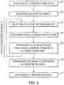
- the process which is detailed at figure 3 can be applied to a multispectral image as represented on the figure 1 .
- the multispectral image 10 can be read from a data storage medium, on which it has been recorded after being inputted. It is then a deferred treatment of the multispectral image.
- the multispectral image 10 may belong to a video stream that is captured and viewed in real time by a monitoring operator.
- the multispectral image capture device (s), an image processing unit capable of implementing the method of the invention, and an image display unit can be embedded in a vehicle. , for example a terrestrial vehicle with surveillance function, or be integrated into individual viewing equipment such as a pair of binoculars.
- the multispectral image capture device (s) 10 can (can) be boarded on board an aircraft, for example an aerial drone, while the image processing and display units may be located in a control and observation station which is static and remote.
- the multispectral images that are captured are transmitted to the processing unit by electromagnetic signals in a manner that is known per se.
- each image 11, 12, 13,..., which corresponds separately to one of the spectral bands of the multispectral image 10 is called the spectral image.
- the analysis window FA is placed in the multispectral image 10, at a position that can be fixed relative to a frame of external spatial limit of image 10, or at a position that can be selected by the surveillance operator.
- the analysis window FA can thus be placed in the center of the multispectral image 10.
- the dimensions of the analysis window FA can vary in particular according to the number and the size of the target zones, described above. after.
- the analysis window FA may be a square of 101 x 101 pixels.
- T 1 , T 2 , T 3 , T 4 ,..., Or generically designated by T i are then selected within the analysis window FA at step E 2.
- One aspect of the invention lies in such use of several target areas for the same analysis window.
- the content of the multispectral image 10 in the analysis window FA is then processed to improve the contrast between each target area and a background area associated with it, independently of the other target areas. This processing produces an elementary image for the content of the multispectral image 10 in the analysis window FA, which is distinct for each target zone T 1 , T 2 , T 3 , T 4 , ...
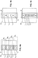
- the target areas T 1 , T 2 , T 3 , T 4 , ... can be vertically aligned within the analysis window FA, as illustrated by the Figures 4a-4c and 4f. Such vertical alignment is particularly suitable for monitoring a landscape landscape by then moving the FA analysis window horizontally in the landscape. Alternatively, the target areas T 1 , T 2 , T 3 , T 4 ,... Can be aligned horizontally in the analysis window FA, for example when this analysis window is then moved in the landscape in one direction. which is contained in a vertical plane. Such a horizontal arrangement of the target areas in the analysis window may be more suitable for multispectral images that are captured from an aerial drone.
- the target areas can be grouped into a block, according to the figure 4d , or to constitute a cross, according to the figure 4e .
- Such configurations are adapted to follow targets that are likely to move relatively slowly in the landscape between two multispectral images captured and then processed successively according to the invention.
- two neighboring target areas may be spaced apart from each other as in the Figures 4a, 4b and 4f , or have partial overlaps, as in the Figures 4c-4e , or be contiguous without overlap or intermediate space.
- each target area T 1 , T 2 , T 3 , T 4 , ... can be a square of 3 x 3, 5 x 5 or 7 x 7 pixels.
- a bottom zone is associated with the target zone T i for which the sequence of steps E3 to E5 is running.
- this bottom zone is separated from the target zone T i by an intermediate guard zone, so that some small targets which are partially contained in the target zone T i do not overflow into the bottom zone.
- the guard area may have a thickness of at least 15 image points between the target area T i and the background area.
- each target zone T 1 , T 2 , T 3 , T 4 can be surrounded by the corresponding bottom area B 1 , B 2 , B 3 , B 4 ,. having inner and outer boundaries which may be square, with an intermediate guard area, denoted G 1 , G 2 , G 3 , G 4 , ... for each pair of target and bottom areas T i -B i .
- the same single bottom zone denoted by B
- the same single bottom zone can be associated with all the target zones T 1 , T 2 , T 3 , T 4 ,.
- the bottom zone B can be arranged around the whole target areas T 1 , T 2 , T 3 , T 4 , ... with a intermediate guard zone which is rated G.
- An advantage of such a second arrangement is to prevent one of the target areas from covering the bottom area which is associated with another of the target areas.
- a scene element which is located in the analysis window FA is processed to calculate the contrast in the multispectral image, either as a potential target within at least one of the target areas, or as background, in a manner that is consistent for all target areas.
- Bottom zone segments which are respectively denoted SB 1 -SB 14 are defined around the target areas T 1 , T 2 , T 3 , T 4 ,..., With an intermediate guard zone G. Then, the bottom zone which is respectively associated with each target zone T i may be constituted by the meeting of several segments SB 1 -SB 14 which are assigned to this target area T i .
- each target zone T i is initially assigned to those bottom zone segments that are the closest spatially to it.
- the bottom area B 1 which is associated with the target area T 1 may be the meeting of the segments SB 1 -SB 5 and SB 13 -SB 14
- the bottom area B 2 which is associated with the target zone T 2 can be the meeting of the segments SB 4 -SB 6 and SB 12 -SB 14
- the bottom area B 3 which is associated with the target area T 3 can be the meeting of the segments SB 5 -SB 7 and SB 11 - SB 13
- the bottom area B 4 which is associated with the target area T 4 may be the meeting of segments SB 6 -SB 12 .
- a fourth possibility to define the background zone that is associated with each target zone T i makes it possible to ensure that the content of the multispectral image in this background zone is fairly homogeneous spectrally.
- a spectral signature can be determined for each of the bottom area segments SB 1 -SB 14 .
- Such a signature can be for example a vector which is constituted by the average values of the intensities of each spectral image 11, 12, 13, ... calculated on all the image points of the image. this bottom zone segment.
- Such a vector therefore has a distinct coordinate for each spectral image.
- the signatures of all the bottom area segments are then compared to each other, and the segment (s) whose signature (s) is (are) furthest away from those of the others. segments is (are) discarded. Only the bottom zone segments that remain after such discrimination can be selected to constitute the bottom area B i which is associated with the target area T i .
- the spectral signatures of the base region segments are given by the following formula, expressed for the background area segment SB j: S j
- k (1 / N j ) ⁇ ⁇ ⁇ image points of segment SBj ⁇ I k (image point), where j is an integer that counts the predefined background area segments, denoted SB j (j varies from 1 to 14 in the example of the figure 4f ), S j is the spectral signature of the bottom zone segment SB j , k is an integer which counts the spectral images 11, 12, 13, ...
- I k is the intensity from the spectral image k to the image point considered
- N j is the number of image points in the background zone segment SB j
- k is the k th coordinate of the signature vector S j .
- each bottom zone it is not necessary for each bottom zone to be contained in the analysis window FA, but some of the bottom zones or the bottom zone that is common to all the target zones. for the implementations concerned, may (may) overflow outside the FA analysis window.
- the zone of Background that is associated with one of the target areas does not necessarily completely surround the target area, but may be arranged only on some of its sides.
- each bottom area or bottom area segment may have a size or thickness in the multispectral image that is greater than or equal to 3 image points, in a spatial direction that is vertical or horizontal by relation to the scene.
- Step E4 ( figure 3 ) is to determine the Fisher projection that maximizes the contrast between each target zone T i and the associated bottom area B i .
- Such a Fisher projection is assumed to be known to the person skilled in the art and has been recalled in the part of this description which relates to the prior art, so that it is not necessary to describe it again.
- the intensity of each image point in the background zone which is associated with one of the target areas can be weighted according to the distance between this image point and the target area, to determine the Fisher projection.
- I k (x, y) designates the intensity value of the coordinate image point (x, y) in the spectral image k
- the values of the weighting coefficients ⁇ i can vary according to any decreasing function of the distance between the image point in the background zone and the target zone. Such weighting can also be used to calculate the signatures of the bottom-zone segments in the fourth possibility that has been presented above.
- step E5 for each of the target areas T i the projection of Fisher that was obtained for this target area is then applied to the multispectral image 10 within the FA window.
- An elementary image is thus obtained, which represents the content of the multispectral image 10 in the analysis window FA with maximum contrast.
- step E6 All the elementary images that are thus obtained from each target area T i are combined in step E6 to construct a single synthetic image.
- a combination can be performed by retaining for each image point in the analysis window FA, that of the intensities at this point among all the elementary images which is the largest.
- the intensities of all the elementary images at this point can be raised to a fixed, common and positive p power, and the intensity of the synthesis image at the image point considered can be equal to the average of these intensities.
- the computer image that was obtained in step E6 in the analysis window FA is presented to the monitoring operator in step E7.
- it can be displayed on a screen, or more generally on a display unit which is intended for visual observation.
- the image that is displayed can be completed outside the analysis window FA by one of the spectral images, for example by a spectral image that corresponds to a heat radiation acquisition channel.
- the image that is displayed can be completed outside the analysis window FA by a combination of several spectral images that correspond to different colors in the visible range, to reconstitute a day vision in color by outside the FA analysis window.
- the dimensions, shapes and positions of the target and background areas that have been given as examples in the detailed description above, can be modified depending on the application and the context of implementation. . In particular, they can be determined from additional data, such as the distance and / or size of a target that is sought in the pictorial scene.
Landscapes
- Physics & Mathematics (AREA)
- General Physics & Mathematics (AREA)
- Engineering & Computer Science (AREA)
- Theoretical Computer Science (AREA)
- Image Processing (AREA)
- Image Analysis (AREA)
Claims (9)
- Verfahren zur Visualisierung eines multispektralen Bilds (10) durch einen Computer auf einer Anzeigevorrichtung, welches aus mehreren spektralen Bildern (11, 12, 13, ...) einer gleichen Szenerie gebildet ist, welche zu einem gleichen Zeitpunkt jeweils in unterschiedlichen spektralen Intervallen aufgenommen worden sind, wobei das Verfahren die folgenden aufeinander folgenden Schritte umfasst:/1/ im Inneren des multispektralen Bilds, Auswählen eines Analysefensters (FA), entsprechend einem Teil der Szenerie, und einer Mehrzahl von Zielzonen (T1, T2, T3, T4, ...) in dem Analysefenster, wobei jede Zielzone einer Bodenzone zugeordnet und von der Bodenzone durch eine Zwischenzone derart getrennt ist, dass jede Zielzone nicht mit der Bodenzone zusammenhängend ist, welche der Zielzone zugeordnet ist;/2/ gesondert für jede Zielzone (T1, T2, T3, T4, ...) in dem Analysefenster (FA), Ausführen der folgenden Unterschritte:/2-1/ Bestimmen einer Fisher-Projektion ausgehend von Intensitätswerten der spektralen Bilder, wobei die Fisher-Projektion eine lineare Kombination der spektralen Bilder (11, 12, 13, ...) ist, welche einen Kontrast zwischen der Zielzone (T1, T2, T3, T4, ...) und der Bodenzone optimiert, welche der Zielzone zugeordnet ist; und/2-2/ Anwenden der Fisher-Projektion, welche in dem Unterschritt /2-1/ bestimmt worden ist, auf die Intensitätswerte der spektralen Bilder (11, 12, 13, ...) in dem Analysefenster (FA), um ein Elementarbild des Teils der Szenerie, welcher in dem Analysefenster enthalten ist, für jede in Schritt /1/ ausgewählte Zielzone (T1, T2, T3, T4, ...) zu erhalten; und dann/3/ Kombinieren der Elementarbilder, um ein Synthesebild bezüglich des Teils der Szenerie zu konstruieren, welcher in dem Analysefenster (FA) enthalten ist; und/4/ Anzeigen eines Bilds der Szenerie an der Anzeigeeinheit unter Verwendung des Synthesebilds, welches in Schritt /3/ erhalten worden ist, in dem Analysefenster (FA),dadurch gekennzeichnet, dass eine gemeinsame Bodenzone (B) sämtlichen der Zielzonen (T1, T2, T3, T4, ...) in dem Analysefenster (FA) zugeordnet ist.
- Verfahren nach Anspruch 1, wobei wenigstens einige der Zielzonen (T1, T2, T3, T4, ...) Überdeckungen untereinander in dem Analysefenster (FA) aufweisen.
- Verfahren nach Anspruch 1 oder 2, wobei die Zielzonen (T1, T2, T3, T4, ...) in dem Analysefenster (FA) ausgerichtet sind.
- Verfahren nach Anspruch 3, wobei die Szenerie eine Erdlandschaft ist und die Zielzonen (T1, T2, T3, T4, ...) parallel zu einer Richtung ausgerichtet sind, welche vertikal oder horizontal bezüglich der Erdlandschaft ist.
- Verfahren nach Anspruch 1 oder 2, wobei die Zielzonen (T1, T2, T3, T4, ...) in dem Analysefenster (FA) derart angeordnet sind, dass sie ein Kreuz oder ein Pflaster bilden.
- Verfahren nach einem der vorhergehenden Ansprüche, wobei in dem Unterschritt /2-1/ für jede Zielzone (T1, T2, T3, T4, ...) des Analysefensters (FA) die Fisher-Projektion durch Gewichten der Intensitätswerte der spektralen Bilder (11, 12, 13,...) in der Bodenzone, welche der Zielzone zugeordnet ist, mit Koeffizienten bestimmt wird, deren Werte absteigende Funktionen eines Abstands zwischen der Zielzone und einer Position in der Bodenzone sind, welcher die Intensitätswerte der spektralen Bilder entsprechen.
- Verfahren nach einem der vorhergehenden Ansprüche, wobei das Synthesebild in Schritt /3/ durch Anwenden einer Intensitäts-Stufenkorrektur auf jedes Elementarbild und anschließendes Zuweisen zu Synthesebildpunkten konstruiert wird, welche in dem Analysefenster liegen, gesondert für jeden der Punkte, der größte der Intensitätswerte zu dem gleichen Punkt aus den korrigierten Elementarbildern, oder durch Zuweisen zu jedem der Synthesebildpunkte in dem Analysefenster eines gewichteten Mittelwerts der Intensitätswerte der korrigierten Elementarbilder, bezüglich des Punkts und erhöht um die Potenz n, wobei n eine positive Ganzzahl ungleich null und festgelegt ist.
- Verfahren nach einem der Ansprüche 1 bis 7, wobei die mehreren Analysefenster (FA) aufeinanderfolgend in dem multispektralen Bild (10) ausgewählt werden und die Reihenfolgen der Schritte /1/ bis /4/ für jedes der Analysefenster wiederholt wird.
- Verfahren nach einem der Ansprüche 1 bis 7, wobei die mehreren multispektralen Bilder (10) aufeinanderfolgend aufgenommen werden und die Reihenfolge der Schritte /1/ bis /4/ für jedes der multispektralen Bilder wiederholt wird, indem das Analysefenster (FA) in der gleichen Weise in allen der multispektralen Bilder ausgewählt wird.
Priority Applications (1)
| Application Number | Priority Date | Filing Date | Title |
|---|---|---|---|
| EP19188204.2A EP3591610B1 (de) | 2015-06-10 | 2016-06-10 | Anzeigeverfahren eines multispektralen bildes |
Applications Claiming Priority (2)
| Application Number | Priority Date | Filing Date | Title |
|---|---|---|---|
| FR1555284A FR3037428B1 (fr) | 2015-06-10 | 2015-06-10 | Procede de visualisation d'une image multispectrale |
| PCT/FR2016/051412 WO2016198803A1 (fr) | 2015-06-10 | 2016-06-10 | Procede de visualisation d'une image multispectrale |
Related Child Applications (2)
| Application Number | Title | Priority Date | Filing Date |
|---|---|---|---|
| EP19188204.2A Division EP3591610B1 (de) | 2015-06-10 | 2016-06-10 | Anzeigeverfahren eines multispektralen bildes |
| EP19188204.2A Division-Into EP3591610B1 (de) | 2015-06-10 | 2016-06-10 | Anzeigeverfahren eines multispektralen bildes |
Publications (2)
| Publication Number | Publication Date |
|---|---|
| EP3308352A1 EP3308352A1 (de) | 2018-04-18 |
| EP3308352B1 true EP3308352B1 (de) | 2019-09-04 |
Family
ID=54545206
Family Applications (2)
| Application Number | Title | Priority Date | Filing Date |
|---|---|---|---|
| EP16739214.1A Active EP3308352B1 (de) | 2015-06-10 | 2016-06-10 | Verfahren zur anzeige eines multispektralen bildes |
| EP19188204.2A Active EP3591610B1 (de) | 2015-06-10 | 2016-06-10 | Anzeigeverfahren eines multispektralen bildes |
Family Applications After (1)
| Application Number | Title | Priority Date | Filing Date |
|---|---|---|---|
| EP19188204.2A Active EP3591610B1 (de) | 2015-06-10 | 2016-06-10 | Anzeigeverfahren eines multispektralen bildes |
Country Status (3)
| Country | Link |
|---|---|
| EP (2) | EP3308352B1 (de) |
| FR (1) | FR3037428B1 (de) |
| WO (1) | WO2016198803A1 (de) |
Families Citing this family (1)
| Publication number | Priority date | Publication date | Assignee | Title |
|---|---|---|---|---|
| FR3154525B1 (fr) * | 2023-10-24 | 2025-11-28 | Safran Electronics & Defense | Procédé d’affichage d’une image multispectrale |
Family Cites Families (2)
| Publication number | Priority date | Publication date | Assignee | Title |
|---|---|---|---|---|
| FR3011663B1 (fr) * | 2013-10-07 | 2015-11-13 | Sagem Defense Securite | Procede de visualisation d'une image multispectrale |
| FR3013876B1 (fr) * | 2013-11-28 | 2016-01-01 | Sagem Defense Securite | Analyse d'une image multispectrale |
-
2015
- 2015-06-10 FR FR1555284A patent/FR3037428B1/fr active Active
-
2016
- 2016-06-10 EP EP16739214.1A patent/EP3308352B1/de active Active
- 2016-06-10 EP EP19188204.2A patent/EP3591610B1/de active Active
- 2016-06-10 WO PCT/FR2016/051412 patent/WO2016198803A1/fr not_active Ceased
Non-Patent Citations (1)
| Title |
|---|
| None * |
Also Published As
| Publication number | Publication date |
|---|---|
| WO2016198803A1 (fr) | 2016-12-15 |
| EP3308352A1 (de) | 2018-04-18 |
| FR3037428A1 (fr) | 2016-12-16 |
| EP3591610B1 (de) | 2021-01-27 |
| FR3037428B1 (fr) | 2017-07-14 |
| EP3591610A1 (de) | 2020-01-08 |
Similar Documents
| Publication | Publication Date | Title |
|---|---|---|
| Herrmann et al. | CNN-based thermal infrared person detection by domain adaptation | |
| EP2776976B1 (de) | Suche nach einem ziel in einem multispektralen bild | |
| EP3074921B1 (de) | Analyse eines multispektralen bildes | |
| KR101824290B1 (ko) | 고해상도 멀티스펙트럼 이미지 캡처 기법 | |
| EP3074920B1 (de) | Analyse eines multispektralen bildes | |
| US9888234B2 (en) | Three-dimensional intergal imaging display device and display system | |
| EP3055832B1 (de) | Verfahren zur betrachtung eines multispektralen bildes | |
| US20130077888A1 (en) | System and Method for Image Enhancement | |
| EP3308352B1 (de) | Verfahren zur anzeige eines multispektralen bildes | |
| CA3003931C (fr) | Procede de decamouflage d'un objet | |
| Chenault et al. | Pyxis handheld polarimetric imager | |
| JP5845858B2 (ja) | 対象検出装置および対象検出方法 | |
| FR3154525A1 (fr) | Procédé d’affichage d’une image multispectrale | |
| EP2415013A1 (de) | Verfahren zum virtuellen vergrössern und erweitern des sichtfelds einer szene | |
| Uzair et al. | Efficient Sampling of Bayer Pattern for Long Range Small Target Detection in Color Images | |
| Bigué et al. | Production of high-resolution reference polarization images from real world scenes | |
| JP2013032920A (ja) | 対象検出装置および対象検出方法 | |
| Dallaire et al. | Enhancing learning-based computer vision algorithms accuracy in sUAS using navigation wide-angle cameras | |
| Belghachem et al. | Three-wavelength laser dazzler soft-countermeasure | |
| Jovanov et al. | Real time demosaicking and superresolution of multispectral images | |
| FR2956944A1 (fr) | Procede et un dispositif de fusion de deux images representant une meme scene dans des bandes spectrales differentes en une image couleur. | |
| FR2962871A3 (fr) | Acquisition d'image par synthese progressive |
Legal Events
| Date | Code | Title | Description |
|---|---|---|---|
| STAA | Information on the status of an ep patent application or granted ep patent |
Free format text: STATUS: THE INTERNATIONAL PUBLICATION HAS BEEN MADE |
|
| PUAI | Public reference made under article 153(3) epc to a published international application that has entered the european phase |
Free format text: ORIGINAL CODE: 0009012 |
|
| STAA | Information on the status of an ep patent application or granted ep patent |
Free format text: STATUS: REQUEST FOR EXAMINATION WAS MADE |
|
| 17P | Request for examination filed |
Effective date: 20171128 |
|
| AK | Designated contracting states |
Kind code of ref document: A1 Designated state(s): AL AT BE BG CH CY CZ DE DK EE ES FI FR GB GR HR HU IE IS IT LI LT LU LV MC MK MT NL NO PL PT RO RS SE SI SK SM TR |
|
| AX | Request for extension of the european patent |
Extension state: BA ME |
|
| DAV | Request for validation of the european patent (deleted) | ||
| DAX | Request for extension of the european patent (deleted) | ||
| GRAP | Despatch of communication of intention to grant a patent |
Free format text: ORIGINAL CODE: EPIDOSNIGR1 |
|
| STAA | Information on the status of an ep patent application or granted ep patent |
Free format text: STATUS: GRANT OF PATENT IS INTENDED |
|
| INTG | Intention to grant announced |
Effective date: 20190529 |
|
| GRAS | Grant fee paid |
Free format text: ORIGINAL CODE: EPIDOSNIGR3 |
|
| GRAA | (expected) grant |
Free format text: ORIGINAL CODE: 0009210 |
|
| STAA | Information on the status of an ep patent application or granted ep patent |
Free format text: STATUS: THE PATENT HAS BEEN GRANTED |
|
| AK | Designated contracting states |
Kind code of ref document: B1 Designated state(s): AL AT BE BG CH CY CZ DE DK EE ES FI FR GB GR HR HU IE IS IT LI LT LU LV MC MK MT NL NO PL PT RO RS SE SI SK SM TR |
|
| REG | Reference to a national code |
Ref country code: GB Ref legal event code: FG4D Free format text: NOT ENGLISH |
|
| REG | Reference to a national code |
Ref country code: CH Ref legal event code: EP |
|
| REG | Reference to a national code |
Ref country code: AT Ref legal event code: REF Ref document number: 1176441 Country of ref document: AT Kind code of ref document: T Effective date: 20190915 |
|
| REG | Reference to a national code |
Ref country code: DE Ref legal event code: R096 Ref document number: 602016019958 Country of ref document: DE |
|
| REG | Reference to a national code |
Ref country code: IE Ref legal event code: FG4D Free format text: LANGUAGE OF EP DOCUMENT: FRENCH |
|
| REG | Reference to a national code |
Ref country code: NL Ref legal event code: FP |
|
| REG | Reference to a national code |
Ref country code: SE Ref legal event code: TRGR |
|
| REG | Reference to a national code |
Ref country code: LT Ref legal event code: MG4D |
|
| PG25 | Lapsed in a contracting state [announced via postgrant information from national office to epo] |
Ref country code: HR Free format text: LAPSE BECAUSE OF FAILURE TO SUBMIT A TRANSLATION OF THE DESCRIPTION OR TO PAY THE FEE WITHIN THE PRESCRIBED TIME-LIMIT Effective date: 20190904 Ref country code: LT Free format text: LAPSE BECAUSE OF FAILURE TO SUBMIT A TRANSLATION OF THE DESCRIPTION OR TO PAY THE FEE WITHIN THE PRESCRIBED TIME-LIMIT Effective date: 20190904 Ref country code: BG Free format text: LAPSE BECAUSE OF FAILURE TO SUBMIT A TRANSLATION OF THE DESCRIPTION OR TO PAY THE FEE WITHIN THE PRESCRIBED TIME-LIMIT Effective date: 20191204 Ref country code: NO Free format text: LAPSE BECAUSE OF FAILURE TO SUBMIT A TRANSLATION OF THE DESCRIPTION OR TO PAY THE FEE WITHIN THE PRESCRIBED TIME-LIMIT Effective date: 20191204 Ref country code: FI Free format text: LAPSE BECAUSE OF FAILURE TO SUBMIT A TRANSLATION OF THE DESCRIPTION OR TO PAY THE FEE WITHIN THE PRESCRIBED TIME-LIMIT Effective date: 20190904 |
|
| PG25 | Lapsed in a contracting state [announced via postgrant information from national office to epo] |
Ref country code: RS Free format text: LAPSE BECAUSE OF FAILURE TO SUBMIT A TRANSLATION OF THE DESCRIPTION OR TO PAY THE FEE WITHIN THE PRESCRIBED TIME-LIMIT Effective date: 20190904 Ref country code: LV Free format text: LAPSE BECAUSE OF FAILURE TO SUBMIT A TRANSLATION OF THE DESCRIPTION OR TO PAY THE FEE WITHIN THE PRESCRIBED TIME-LIMIT Effective date: 20190904 Ref country code: AL Free format text: LAPSE BECAUSE OF FAILURE TO SUBMIT A TRANSLATION OF THE DESCRIPTION OR TO PAY THE FEE WITHIN THE PRESCRIBED TIME-LIMIT Effective date: 20190904 Ref country code: GR Free format text: LAPSE BECAUSE OF FAILURE TO SUBMIT A TRANSLATION OF THE DESCRIPTION OR TO PAY THE FEE WITHIN THE PRESCRIBED TIME-LIMIT Effective date: 20191205 Ref country code: ES Free format text: LAPSE BECAUSE OF FAILURE TO SUBMIT A TRANSLATION OF THE DESCRIPTION OR TO PAY THE FEE WITHIN THE PRESCRIBED TIME-LIMIT Effective date: 20190904 |
|
| REG | Reference to a national code |
Ref country code: AT Ref legal event code: MK05 Ref document number: 1176441 Country of ref document: AT Kind code of ref document: T Effective date: 20190904 |
|
| PG25 | Lapsed in a contracting state [announced via postgrant information from national office to epo] |
Ref country code: PL Free format text: LAPSE BECAUSE OF FAILURE TO SUBMIT A TRANSLATION OF THE DESCRIPTION OR TO PAY THE FEE WITHIN THE PRESCRIBED TIME-LIMIT Effective date: 20190904 Ref country code: AT Free format text: LAPSE BECAUSE OF FAILURE TO SUBMIT A TRANSLATION OF THE DESCRIPTION OR TO PAY THE FEE WITHIN THE PRESCRIBED TIME-LIMIT Effective date: 20190904 Ref country code: EE Free format text: LAPSE BECAUSE OF FAILURE TO SUBMIT A TRANSLATION OF THE DESCRIPTION OR TO PAY THE FEE WITHIN THE PRESCRIBED TIME-LIMIT Effective date: 20190904 Ref country code: RO Free format text: LAPSE BECAUSE OF FAILURE TO SUBMIT A TRANSLATION OF THE DESCRIPTION OR TO PAY THE FEE WITHIN THE PRESCRIBED TIME-LIMIT Effective date: 20190904 Ref country code: PT Free format text: LAPSE BECAUSE OF FAILURE TO SUBMIT A TRANSLATION OF THE DESCRIPTION OR TO PAY THE FEE WITHIN THE PRESCRIBED TIME-LIMIT Effective date: 20200106 |
|
| PG25 | Lapsed in a contracting state [announced via postgrant information from national office to epo] |
Ref country code: CZ Free format text: LAPSE BECAUSE OF FAILURE TO SUBMIT A TRANSLATION OF THE DESCRIPTION OR TO PAY THE FEE WITHIN THE PRESCRIBED TIME-LIMIT Effective date: 20190904 Ref country code: SK Free format text: LAPSE BECAUSE OF FAILURE TO SUBMIT A TRANSLATION OF THE DESCRIPTION OR TO PAY THE FEE WITHIN THE PRESCRIBED TIME-LIMIT Effective date: 20190904 Ref country code: SM Free format text: LAPSE BECAUSE OF FAILURE TO SUBMIT A TRANSLATION OF THE DESCRIPTION OR TO PAY THE FEE WITHIN THE PRESCRIBED TIME-LIMIT Effective date: 20190904 Ref country code: IS Free format text: LAPSE BECAUSE OF FAILURE TO SUBMIT A TRANSLATION OF THE DESCRIPTION OR TO PAY THE FEE WITHIN THE PRESCRIBED TIME-LIMIT Effective date: 20200224 |
|
| REG | Reference to a national code |
Ref country code: DE Ref legal event code: R097 Ref document number: 602016019958 Country of ref document: DE |
|
| PLBE | No opposition filed within time limit |
Free format text: ORIGINAL CODE: 0009261 |
|
| STAA | Information on the status of an ep patent application or granted ep patent |
Free format text: STATUS: NO OPPOSITION FILED WITHIN TIME LIMIT |
|
| PG2D | Information on lapse in contracting state deleted |
Ref country code: IS |
|
| PG25 | Lapsed in a contracting state [announced via postgrant information from national office to epo] |
Ref country code: DK Free format text: LAPSE BECAUSE OF FAILURE TO SUBMIT A TRANSLATION OF THE DESCRIPTION OR TO PAY THE FEE WITHIN THE PRESCRIBED TIME-LIMIT Effective date: 20190904 Ref country code: IS Free format text: LAPSE BECAUSE OF FAILURE TO SUBMIT A TRANSLATION OF THE DESCRIPTION OR TO PAY THE FEE WITHIN THE PRESCRIBED TIME-LIMIT Effective date: 20200105 |
|
| 26N | No opposition filed |
Effective date: 20200605 |
|
| PG25 | Lapsed in a contracting state [announced via postgrant information from national office to epo] |
Ref country code: SI Free format text: LAPSE BECAUSE OF FAILURE TO SUBMIT A TRANSLATION OF THE DESCRIPTION OR TO PAY THE FEE WITHIN THE PRESCRIBED TIME-LIMIT Effective date: 20190904 |
|
| PG25 | Lapsed in a contracting state [announced via postgrant information from national office to epo] |
Ref country code: MC Free format text: LAPSE BECAUSE OF FAILURE TO SUBMIT A TRANSLATION OF THE DESCRIPTION OR TO PAY THE FEE WITHIN THE PRESCRIBED TIME-LIMIT Effective date: 20190904 |
|
| REG | Reference to a national code |
Ref country code: CH Ref legal event code: PL |
|
| PG25 | Lapsed in a contracting state [announced via postgrant information from national office to epo] |
Ref country code: LU Free format text: LAPSE BECAUSE OF NON-PAYMENT OF DUE FEES Effective date: 20200610 |
|
| REG | Reference to a national code |
Ref country code: BE Ref legal event code: MM Effective date: 20200630 |
|
| PG25 | Lapsed in a contracting state [announced via postgrant information from national office to epo] |
Ref country code: IE Free format text: LAPSE BECAUSE OF NON-PAYMENT OF DUE FEES Effective date: 20200610 Ref country code: LI Free format text: LAPSE BECAUSE OF NON-PAYMENT OF DUE FEES Effective date: 20200630 Ref country code: CH Free format text: LAPSE BECAUSE OF NON-PAYMENT OF DUE FEES Effective date: 20200630 |
|
| PG25 | Lapsed in a contracting state [announced via postgrant information from national office to epo] |
Ref country code: BE Free format text: LAPSE BECAUSE OF NON-PAYMENT OF DUE FEES Effective date: 20200630 |
|
| PG25 | Lapsed in a contracting state [announced via postgrant information from national office to epo] |
Ref country code: TR Free format text: LAPSE BECAUSE OF FAILURE TO SUBMIT A TRANSLATION OF THE DESCRIPTION OR TO PAY THE FEE WITHIN THE PRESCRIBED TIME-LIMIT Effective date: 20190904 Ref country code: MT Free format text: LAPSE BECAUSE OF FAILURE TO SUBMIT A TRANSLATION OF THE DESCRIPTION OR TO PAY THE FEE WITHIN THE PRESCRIBED TIME-LIMIT Effective date: 20190904 Ref country code: CY Free format text: LAPSE BECAUSE OF FAILURE TO SUBMIT A TRANSLATION OF THE DESCRIPTION OR TO PAY THE FEE WITHIN THE PRESCRIBED TIME-LIMIT Effective date: 20190904 |
|
| PG25 | Lapsed in a contracting state [announced via postgrant information from national office to epo] |
Ref country code: MK Free format text: LAPSE BECAUSE OF FAILURE TO SUBMIT A TRANSLATION OF THE DESCRIPTION OR TO PAY THE FEE WITHIN THE PRESCRIBED TIME-LIMIT Effective date: 20190904 |
|
| PGFP | Annual fee paid to national office [announced via postgrant information from national office to epo] |
Ref country code: DE Payment date: 20250618 Year of fee payment: 10 |
|
| PGFP | Annual fee paid to national office [announced via postgrant information from national office to epo] |
Ref country code: GB Payment date: 20250625 Year of fee payment: 10 |
|
| PGFP | Annual fee paid to national office [announced via postgrant information from national office to epo] |
Ref country code: NL Payment date: 20250625 Year of fee payment: 10 |
|
| PGFP | Annual fee paid to national office [announced via postgrant information from national office to epo] |
Ref country code: FR Payment date: 20250623 Year of fee payment: 10 |
|
| PGFP | Annual fee paid to national office [announced via postgrant information from national office to epo] |
Ref country code: SE Payment date: 20250618 Year of fee payment: 10 |
|
| PGFP | Annual fee paid to national office [announced via postgrant information from national office to epo] |
Ref country code: IT Payment date: 20250630 Year of fee payment: 10 |