EP3308231B1 - Device with monitored device cooling - Google Patents
Device with monitored device cooling Download PDFInfo
- Publication number
- EP3308231B1 EP3308231B1 EP16730786.7A EP16730786A EP3308231B1 EP 3308231 B1 EP3308231 B1 EP 3308231B1 EP 16730786 A EP16730786 A EP 16730786A EP 3308231 B1 EP3308231 B1 EP 3308231B1
- Authority
- EP
- European Patent Office
- Prior art keywords
- operating state
- cooling
- components
- monitoring unit
- welding
- Prior art date
- Legal status (The legal status is an assumption and is not a legal conclusion. Google has not performed a legal analysis and makes no representation as to the accuracy of the status listed.)
- Active
Links
Images


Classifications
-
- B—PERFORMING OPERATIONS; TRANSPORTING
- B23—MACHINE TOOLS; METAL-WORKING NOT OTHERWISE PROVIDED FOR
- B23K—SOLDERING OR UNSOLDERING; WELDING; CLADDING OR PLATING BY SOLDERING OR WELDING; CUTTING BY APPLYING HEAT LOCALLY, e.g. FLAME CUTTING; WORKING BY LASER BEAM
- B23K9/00—Arc welding or cutting
- B23K9/32—Accessories
- B23K9/321—Protecting means
-
- B—PERFORMING OPERATIONS; TRANSPORTING
- B23—MACHINE TOOLS; METAL-WORKING NOT OTHERWISE PROVIDED FOR
- B23K—SOLDERING OR UNSOLDERING; WELDING; CLADDING OR PLATING BY SOLDERING OR WELDING; CUTTING BY APPLYING HEAT LOCALLY, e.g. FLAME CUTTING; WORKING BY LASER BEAM
- B23K11/00—Resistance welding; Severing by resistance heating
- B23K11/24—Electric supply or control circuits therefor
- B23K11/241—Electric supplies
-
- B—PERFORMING OPERATIONS; TRANSPORTING
- B23—MACHINE TOOLS; METAL-WORKING NOT OTHERWISE PROVIDED FOR
- B23K—SOLDERING OR UNSOLDERING; WELDING; CLADDING OR PLATING BY SOLDERING OR WELDING; CUTTING BY APPLYING HEAT LOCALLY, e.g. FLAME CUTTING; WORKING BY LASER BEAM
- B23K37/00—Auxiliary devices or processes, not specially adapted to a procedure covered by only one of the preceding main groups
- B23K37/003—Cooling means
-
- B—PERFORMING OPERATIONS; TRANSPORTING
- B23—MACHINE TOOLS; METAL-WORKING NOT OTHERWISE PROVIDED FOR
- B23K—SOLDERING OR UNSOLDERING; WELDING; CLADDING OR PLATING BY SOLDERING OR WELDING; CUTTING BY APPLYING HEAT LOCALLY, e.g. FLAME CUTTING; WORKING BY LASER BEAM
- B23K37/00—Auxiliary devices or processes, not specially adapted to a procedure covered by only one of the preceding main groups
- B23K37/006—Safety devices
-
- B—PERFORMING OPERATIONS; TRANSPORTING
- B23—MACHINE TOOLS; METAL-WORKING NOT OTHERWISE PROVIDED FOR
- B23K—SOLDERING OR UNSOLDERING; WELDING; CLADDING OR PLATING BY SOLDERING OR WELDING; CUTTING BY APPLYING HEAT LOCALLY, e.g. FLAME CUTTING; WORKING BY LASER BEAM
- B23K9/00—Arc welding or cutting
- B23K9/095—Monitoring or automatic control of welding parameters
- B23K9/0953—Monitoring or automatic control of welding parameters using computing means
-
- B—PERFORMING OPERATIONS; TRANSPORTING
- B23—MACHINE TOOLS; METAL-WORKING NOT OTHERWISE PROVIDED FOR
- B23K—SOLDERING OR UNSOLDERING; WELDING; CLADDING OR PLATING BY SOLDERING OR WELDING; CUTTING BY APPLYING HEAT LOCALLY, e.g. FLAME CUTTING; WORKING BY LASER BEAM
- B23K9/00—Arc welding or cutting
- B23K9/10—Other electric circuits therefor; Protective circuits; Remote controls
- B23K9/1006—Power supply
- B23K9/1043—Power supply characterised by the electric circuit
- B23K9/1056—Power supply characterised by the electric circuit by using digital means
- B23K9/1062—Power supply characterised by the electric circuit by using digital means with computing means
-
- G—PHYSICS
- G05—CONTROLLING; REGULATING
- G05B—CONTROL OR REGULATING SYSTEMS IN GENERAL; FUNCTIONAL ELEMENTS OF SUCH SYSTEMS; MONITORING OR TESTING ARRANGEMENTS FOR SUCH SYSTEMS OR ELEMENTS
- G05B19/00—Programme-control systems
- G05B19/02—Programme-control systems electric
- G05B19/18—Numerical control [NC], i.e. automatically operating machines, in particular machine tools, e.g. in a manufacturing environment, so as to execute positioning, movement or co-ordinated operations by means of programme data in numerical form
- G05B19/406—Numerical control [NC], i.e. automatically operating machines, in particular machine tools, e.g. in a manufacturing environment, so as to execute positioning, movement or co-ordinated operations by means of programme data in numerical form characterised by monitoring or safety
-
- G—PHYSICS
- G05—CONTROLLING; REGULATING
- G05B—CONTROL OR REGULATING SYSTEMS IN GENERAL; FUNCTIONAL ELEMENTS OF SUCH SYSTEMS; MONITORING OR TESTING ARRANGEMENTS FOR SUCH SYSTEMS OR ELEMENTS
- G05B23/00—Testing or monitoring of control systems or parts thereof
- G05B23/02—Electric testing or monitoring
- G05B23/0205—Electric testing or monitoring by means of a monitoring system capable of detecting and responding to faults
- G05B23/0218—Electric testing or monitoring by means of a monitoring system capable of detecting and responding to faults characterised by the fault detection method dealing with either existing or incipient faults
- G05B23/0224—Process history based detection method, e.g. whereby history implies the availability of large amounts of data
- G05B23/0227—Qualitative history assessment, whereby the type of data acted upon, e.g. waveforms, images or patterns, is not relevant, e.g. rule based assessment; if-then decisions
- G05B23/0232—Qualitative history assessment, whereby the type of data acted upon, e.g. waveforms, images or patterns, is not relevant, e.g. rule based assessment; if-then decisions based on qualitative trend analysis, e.g. system evolution
-
- G—PHYSICS
- G05—CONTROLLING; REGULATING
- G05B—CONTROL OR REGULATING SYSTEMS IN GENERAL; FUNCTIONAL ELEMENTS OF SUCH SYSTEMS; MONITORING OR TESTING ARRANGEMENTS FOR SUCH SYSTEMS OR ELEMENTS
- G05B23/00—Testing or monitoring of control systems or parts thereof
- G05B23/02—Electric testing or monitoring
- G05B23/0205—Electric testing or monitoring by means of a monitoring system capable of detecting and responding to faults
- G05B23/0218—Electric testing or monitoring by means of a monitoring system capable of detecting and responding to faults characterised by the fault detection method dealing with either existing or incipient faults
- G05B23/0243—Electric testing or monitoring by means of a monitoring system capable of detecting and responding to faults characterised by the fault detection method dealing with either existing or incipient faults model based detection method, e.g. first-principles knowledge model
- G05B23/0245—Electric testing or monitoring by means of a monitoring system capable of detecting and responding to faults characterised by the fault detection method dealing with either existing or incipient faults model based detection method, e.g. first-principles knowledge model based on a qualitative model, e.g. rule based; if-then decisions
-
- G—PHYSICS
- G05—CONTROLLING; REGULATING
- G05B—CONTROL OR REGULATING SYSTEMS IN GENERAL; FUNCTIONAL ELEMENTS OF SUCH SYSTEMS; MONITORING OR TESTING ARRANGEMENTS FOR SUCH SYSTEMS OR ELEMENTS
- G05B23/00—Testing or monitoring of control systems or parts thereof
- G05B23/02—Electric testing or monitoring
- G05B23/0205—Electric testing or monitoring by means of a monitoring system capable of detecting and responding to faults
- G05B23/0259—Electric testing or monitoring by means of a monitoring system capable of detecting and responding to faults characterized by the response to fault detection
- G05B23/0275—Fault isolation and identification, e.g. classify fault; estimate cause or root of failure
-
- H—ELECTRICITY
- H05—ELECTRIC TECHNIQUES NOT OTHERWISE PROVIDED FOR
- H05K—PRINTED CIRCUITS; CASINGS OR CONSTRUCTIONAL DETAILS OF ELECTRIC APPARATUS; MANUFACTURE OF ASSEMBLAGES OF ELECTRICAL COMPONENTS
- H05K7/00—Constructional details common to different types of electric apparatus
- H05K7/20—Modifications to facilitate cooling, ventilating, or heating
- H05K7/20009—Modifications to facilitate cooling, ventilating, or heating using a gaseous coolant in electronic enclosures
- H05K7/20209—Thermal management, e.g. fan control
Definitions
- the invention relates to a device with monitored device cooling and a method for monitoring an operating state of a device cooling in a device, in particular in an energy device that provides or converts an electric current.
- energy devices include battery chargers, inverters, and welders.
- Welding machines have a welding power source, which supplies an electric current to carry out the welding process.
- a welding inverter is an electronic welding power source. Inverter welding equipment is used for various arc welding processes, such as electrode, MIG / MAG, plasma and TIG / TIG welding. Such devices are connected depending on the power one or three phases to a power grid.
- the mains voltage is first rectified and chopped using power semiconductors and transformed by means of a relatively small transformer to a low voltage. Subsequently, the welding current is rectified by means of suitable diodes.
- Energy devices in particular welding power sources, may comprise a multiplicity of different electronic or electromechanical components.
- the power and duty cycle of the welding power source is limited by the permissible component temperatures in the device. If a limit temperature is reached, the device switches off until the component in question has cooled down again.
- Conventional welding machines may have monitoring electronics.
- the DE 196 260 59 A1 describes a welding device with a monitoring electronics, which emits a signal to a switching element when a setpoint is exceeded in order to trigger a switching operation. In this way, in the event of a defect within the welding device, the operating personnel may be at risk of danger to be protected. For example, when a limit temperature is reached, the welding device can be switched off.
- DE 10 2005 058 351 A1 discloses a method of monitoring a welding inverter for resistance welding, wherein a temperature profile is recorded for monitoring the welding inverter, in particular for performing a lifetime estimation.
- US 2009/299531 A1 discloses an electronic device having a deviation value calculation unit that calculates a deviation value from the normal limit of the ratio between a performance index associated with the drive power and the measured rotational speed of the fan, a clogging detection unit; detects, by the deviation value, blockages in an air passage through which the fan sucks air outside the housing and sends to the heater, and a deviation value correction unit that corrects the deviation value according to the aging of the fan's performance, deterioration of the clogging detection capacity caused by the aging compensate the obstruction detection unit.
- the device has a user interface which has a display unit for displaying the operating state deviation of the device cooling, the determined cause of the operating state deviation and instructions for eliminating the determined cause of the operating state deviation of the device cooling.
- the user interface further comprises an input unit for adjusting the current by a user and / or by a central control of a system.
- the components have electronic and / or electromechanical components which have associated cooling units for cooling the respective component.
- the device cooling as a component on at least one ventilation unit which supplies cooling air from the environment of the device further components along a cooling air path within a housing of the device.
- the components along the cooling air path associated with temperature sensors that detect an operating temperature profile at the respective components and report to the monitoring unit of the device.
- this has a current measuring unit, which measures the set current and reports to the monitoring unit.
- the monitoring unit controls at least one actuator, in particular a cooling unit and / or a ventilation unit, as a function of the current operating state of the device cooling.
- the monitoring unit has access to a data memory which stores a data model of the device, in particular a data model of the components contained therein and their spatial position along the cooling air path.
- the monitoring unit reports the operating state of the device cooling via a network interface of the device to a central control of a system.
- the invention further provides a method for monitoring an operating state of a device cooling in a device having the features specified in claim 10.
- an operating state deviation of the device cooling and at least one detected potential cause of the operating state deviation as well as instructions for remedying the corresponding cause via a user interface and / or a network interface of the device are output.
- Fig. 1 shows a schematic block diagram illustrating an embodiment of a device according to the invention 1.
- the device 1 is a possible embodiment of a welding device that supplies a welding torch with an adjustable electrical current.
- the welding apparatus 1 may contain a plurality of different components or components, which are used on the one hand as control electronics and on the other for power electronic purposes. These components or components include, for example, electronic or electromechanical components.
- Fig. 1 schematically shows two components 2-1, 2-2, which are, for example, electronic components or electronic assemblies.
- the two components or assemblies 2-1, 2-2 have an operating temperature T, which is detected in the illustrated embodiment via an associated temperature sensor 3-1, 3-2.
- the temperature sensors each detect an operating temperature profile T (t) of the associated component or the associated module, in particular a power unit, within the welding device 1.
- the temperature sensors 3-1, 3-2 can directly on the associated component 2-1, 2-2 be appropriate or in immediate spatial proximity of the relevant component 2-i are located.
- the components or modules 2-i each have at least one integrated temperature sensor 3-i, which senses the operating temperature curve T (t) of the relevant component 2-i.
- the integrated temperature sensors 3-i are connected via signal lines 4-1, 4-2 to a monitoring unit 5.
- the temperature sensors 3-1, 3-2 transmit the operating temperature curve T (t) of the associated component 2-i to the monitoring unit 5.
- the monitoring unit 5 monitors the operating state of a welding device cooling of the welding device based on the detected operating temperature profiles and a set welding current I of the welding device 1 1.
- the welding device 1 includes a ventilation unit 6, which is connected to the monitoring unit 5 via lines 7.
- the ventilation unit 6 and the fan attracts cooling ambient air from the environment of the welding device 1, wherein the cooling air L along a cooling air path 8 within the welding device 1 to the components 2-1, 2-2 and / or on the cooling fins of the Part cooling provided for cooling the cooling passes and emerges at another location from the housing of the welding device 1, as shown schematically in FIG Fig. 1 shown.
- the ventilation unit 6 may for example also be part of a liquid cooling by the liquid is cooled with the ambient air - for example via a heat exchanger.
- the welding device cooling comprises the ventilation unit 6 for cooling the components 2-1, 2-2.
- the electronic or electromechanical components 2-i also each have associated cooling units for cooling the respective component 2-i. These cooling units are, for example, heat sinks which are attached or screwed to the respective component 2-i.
- the components 2-i along the cooling air path 8 preferably each have an associated temperature sensor 3-i, which reports an operating temperature curve T (t) at the respective component 2-i to the monitoring unit 5 of the welding device 1. The transmission of the operating temperature data via the signal lines 4-i.
- the temperature sensors 3-i preferably continuously detect the operating temperature of the respective associated component 2-i.
- the monitoring unit 5 can derive or determine the expected operating state of the welding device cooling, so that these serve as reference values.
- the operating temperature profiles T (t) currently reported by the temperature sensors 3-i on the components 2-i within the cooling section 8 can be compared by the monitoring unit 5 with the expected operating temperature profiles.
- the monitoring unit 5 carries out an analysis of the detected operating temperature profiles of different components 2-i for determining at least one potential cause of the operating state deviation that has occurred.
- the welding device 1 additionally has at least one further temperature sensor 9, which reports an ambient temperature prevailing in the surroundings of the welding device 1 to the monitoring unit 5 of the welding device 1.
- the ambient temperature sensor 9 can be arranged on the outside of the housing and / or directly on the inside of the housing. Thus, factors such as direct sunlight or weather influences are generally taken into account on the welding machine 1. This can also be done as necessary depending on the time of day. This ambient temperature is preferably taken into account by the monitoring unit 5 for carrying out the analysis.
- the welding device or the current source 1 supplies a welding current I to an external welding unit, in particular a welding torch.
- the current I delivered by the welding device 1 is measured by a current measuring unit 10 integrated in the welding device 1 and reported to the monitoring unit 5 as a parameter. On the basis of this additional parameter, the monitoring unit 5 can determine the normal expected operating state.
- parameters such as voltage curves, controller states, constant current / constant voltage characteristic curve or other dynamic processes, the selected welding characteristic curve, etc. can be used as parameters.
- the welding device 1 has a user interface 11 for a user of the welding device 1, for example, a welder.
- the user interface 11 preferably has a display unit which is used for displaying an operating state deviation of the welding device cooling, a determined cause of the operating state deviation and for issuing instructions for eliminating the determined cause of the operating state deviation due to the analysis performed.
- the user interface 11 may also include an input unit for adjusting the welding current I by the user.
- the welding device 1 also has a network interface 12, which connects the welding device 1 to a central control of a system via a network, in particular a data network. In one possible embodiment, this central controller can monitor and control various devices, in particular welding devices 1.
- the monitoring unit 5 reports via the network interface 12 of the welding device 1 the operating state of the welding device cooling of the welding device 1 to the central control of the system.
- the monitoring unit 5 controls at least one actuator of the welding device 1 as a function of the instantaneous operating state of the welding device cooling system. In one possible embodiment, it controls the monitoring unit 5 in dependence on the current operating state of the welding device cooling the cooling unit within the welding device 1 or a ventilation unit, for example the fan 6, according to the current operating state of the welding device cooling. In one possible embodiment, the monitoring unit 5 also has access to a data memory which stores a data model of the welding device 1. This stored data model preferably comprises the components or assemblies 2-i contained in the welding apparatus 1 and their absolute or relative spatial position relative to each other along the cooling air path 8. The data model also includes, for example, reference values as to how the cooling air path 8 behaves at different ambient temperatures.
- the monitoring unit 5 may in one possible embodiment include one or more microprocessors which execute a monitoring program.
- the monitoring unit 5 - which may also be integrated in the control of the current source - carries out an intelligent evaluation of the temperature profiles supplied by the temperature sensors 3-i within the welding device 1 and performs an analysis as to why the cooling capacity within the cooling air section 8 has decreased.
- the analysis of the welding machine cooling is performed by the monitoring unit 5 in order to find out potential causes for this operating state deviation.
- the monitoring unit 5 reports on the display unit of the user interface 11 the occurred operating state deviation of the welding machine cooling and at the same time gives hints for the elimination of the determined potential cause of this operating state change.
- the user When a change in operating state occurs, the user also receives an exact error description and instructions for remedying the determined potential cause of the error.
- the maintenance of the welding apparatus 1 in terms considerably simplified cooling and shortened the duration of the maintenance.
- the operating state of the device cooling is monitored, so that errors that have occurred are recognized early, ie not only when limit temperatures are exceeded.
- the resulting early elimination of the defective cooling means that the components 2-i contained in the device 1 are exposed on average to a lower average temperature and thus have a significantly higher operating life expectancy.
- the lifetime or operating time of the device 1 is significantly increased overall.
- the deterioration of the cooling performance is indicated to the operator at an early stage (eg with colors), whereby this can infer the maximum possible duty cycle.
- This is crucial for a welding process, whether a weld can be performed without interruption. It must therefore be the set power over the entire duration of the weld available. Thus, an unexpected termination of welding processes can be prevented, thereby avoiding scrap parts.
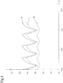
- FIGS. 3 to 6 illustrated temperature profiles exemplified.
- the diagrams show the temperature T of components, for example the in Fig. 1 represented components 2-1, 2-2, over time t.
- the temperature profiles shown there can be detected by temperature sensors, for example, the in Fig. 1 represented temperature sensors 3-1, 3-2 recorded.
- Fig. 3 shows an exemplary temperature profile T (t) in a welder 1 with working cooling at an ambient temperature of 40 ° C.
- this has a relation to the ambient temperature slightly elevated relatively constant temperature of, for example, about 42 ° C, as in Fig. 3 represented by curve III.
- the curves I, II show the temperature profile of two components within the welding apparatus 1, for example, the components 2-1, 2-2 in Fig. 1 , How to get in Fig. 3 can recognize the temperature profile is periodic in both components 2-i, the operating temperature during a welding period increases and drops during a subsequent welding break.
- Fig. 4 shows the temperature curves T (t) at an elevated ambient temperature of 50 ° C with functioning cooling of the welding device 1.
- the ambient temperature is reported for example by the ambient temperature sensor 9 of the monitoring unit 5.
- the curves of the curves I to III are as in Fig. 3 , but shifted upwards by the value of the higher ambient temperature.
- the temperature in normal operation is about 55 ° C.
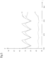
- Fig. 5 shows the temperature curves T (t) at the two components 2-1, 2-2 at an ambient temperature of 40 ° C with blocked cooling air supply. How to get out Fig. 5 can recognize the temperature T within the welding device 1 outside the cooling air path 8 within the housing of the welding device 1 slightly above the temperature profile in Fig. 3 (Curve III), while the temperature profiles reported by the temperature sensors 3-1, 3-2 of the two components 2-1, 2-2 are both significantly increased. This is a clear indication that the cooling air supply is blocked within the cooling section 8 within the welding device 1 due to a faulty fan 6. Due to the faulty fan 6, the temperature curves T (t) of the two components 2-1, 2-2 (curve I, curve II) contained in the cooling air section 8 shift in parallel upward.
- Fig. 6 shows the temperature curves T (t) at an ambient temperature of 40 ° C after the occurrence of another error.
- curve I the temperature profile, which is transmitted from the sensor 3-1 of the first component 2-1 to the monitoring unit 5, in comparison to the temperature profile according to Fig. 3 clearly increased.
- the temperature fluctuations on the first component 2-1 are significantly larger compared to the temperature fluctuations on the other component 2-2 (curve II).
- the monitoring unit 5 close to a fault in the cooling unit of the first component 2-1 (curve I). If this component 2-1 has, for example, a heat sink which is screwed to the component 2-1, it can be made of the in Fig.
- the monitoring unit 5 can carry out the analysis of the different temperature profiles T (t) taking into account the ambient temperature T U and the currently delivered welding power in order to detect possible deviations from a normal operating state of the cooling.
- an analysis can be made by analyzing the temperature profiles T (t), the ambient temperature T U (t), the rotational speed of the fan 6 and / or the output welding current I according to the welding power possible causes of faults are responsible for the temperature variations that have occurred.
- the cooling times can also be recorded. From the cooling time of the operating state of the cooling can be determined or derived. For example, reference values can be stored for this purpose.
- the monitoring unit 5 can sort different possible causes of error according to their probability and display them to the user via the user interface 11.
- the monitoring unit 5 has access to an internal or external data memory, which contains a data model of the welding device 1.
- This data model preferably specifies the components contained in the welding apparatus 1 and preferably their spatial position along the cooling air path 8.
- the monitoring unit 5 can refine the analysis of the temperature profiles T (t) reported to it, as it emerges from the data model how the relative position of the various components 2-i is within the cooling air gap 8.
- the occurring operating state deviations of the cooling and the analysis results can be reported in a possible embodiment of the monitoring unit 5 via the network interface 12 of a central control system of a plant to cause the necessary maintenance.
- the monitoring unit 5 can detect a wide variety of error causes or operating state deviations, for example, that the supply of cooling air in the cooling air path 8 is blocked or a heat sink in the welding machine 1 is occupied or dirty. Further possible error states or causes of errors are, for example, an excessively high ambient temperature T U in the environment of the welding device 1 or that individual cooling units are defective or impaired. This makes it possible for the maintenance personnel to preventively perform a maintenance of the cooling of the welding device 1 before critical limit temperatures are reached at the affected component 2-i within the welding device 1. If the ambient temperature is too high, the maintenance personnel can ensure sufficient cooling of the ambient air of the welding power source. This has the consequence that an unwanted failure of the welding device 1 can be preventively avoided within the system, so that the productivity of the system is increased.
- error states or causes of errors are, for example, an excessively high ambient temperature T U in the environment of the welding device 1 or that individual cooling units are defective or impaired.
- the life of the various components 2-i within of the welding apparatus 1 is increased by avoiding too high temperatures.
- the monitoring unit 5 can also selectively control actuators within the welding device 1 in order to avoid consequences of the error that has occurred. If, for example, the monitoring unit 5 detects on the basis of the temperature profiles reported to it that the local cooling unit of the component 2-1 within the cooling section 8 is faulty or has completely failed, it can control the fan 6 for the transitional correction or alleviation of the error such that the cooling of the affected component 2-1 is increased. For example, the speed of the fan 6 can be increased to the maximum value.
- the monitoring unit 5 can then operate the fan 6 again normally.
- a message can also be sent to the user / operator so that he carries out a targeted check of the affected component 2-1.
- measures for troubleshooting such as tightening screw connections to heat sinks or removing local contamination.
- soiling can also be removed, for example, by changing the running direction of the fan 6.
- compressed air or a protective gas required for the welding process can also be blown through a filter by means of an actuator so that it is cleaned and more supply air can be sucked in again.
- the temperature sensors 3-1, 3-2 can also be arranged such that they detect a temperature at the inlet and at the outlet of the cooling air plug 8 of the cooling air L. It can also be used for additional temperature sensors. From this, a heat balance can be determined by the monitoring unit 5 and conclusions drawn on possible errors. For this, a data model, reference values, etc. can be used - as already described.
- Fig. 2 shows a flowchart for illustrating an embodiment of the inventive method for monitoring an operating state of a device cooling in a device, for example, the in Fig. 1 illustrated welding machine 1.
- a first step S1 an operating temperature curve T (t) of at least one component 2-i of the device 1 is detected.
- step S2 the operating state of the device cooling is determined on the basis of the at least one detected operating temperature profile and a power provided by the device 1.
- the detected operating temperature curves T (t) of the components for detecting at least one potential cause of the operating state deviation of the device cooling in a possible embodiment of the method according to the invention are analyzed in step S3.
- the operating state deviation of the device cooling and at least one detected potential cause of the operating state deviation is output via a user interface or a network interface of the device 1 in step S4.
- instructions for eliminating the corresponding cause via the user interface and / or the network interface to a user or a central controller are preferably output in step S4.
- the monitoring unit 5 can carry out a check as to whether the corresponding maintenance measure has led to a correction of the operating state deviation of the device cooling and thus the maintenance measure was successful.
- the illustrated method is preferably executed by a monitoring program that runs on a microprocessor of the monitoring unit 5.
- This monitoring program can be loaded in a possible embodiment via the network interface 12 of the device 1 in a program memory of the monitoring unit 5.
- the corresponding monitoring program is loaded via a network from a server which is operated, for example, by the manufacturer of the device 1.
- the monitoring unit 5 in another possible embodiment has a further data memory for storing the data model of the components or assemblies contained in the device 1.
- this data model of the device 1 can likewise be downloaded via the network interface 12 from a database or a server.
- the loaded data model can take into account different configurations or variants of the device 1.
- the monitoring unit 5 is integrated in the device 1.
- the monitoring unit 5 may also be integrated in a central control of a system which is connected via a network to one or more devices 1.
- the central control of the system can dynamically adapt various maintenance plans for various devices, in particular welding devices 1, in accordance with the reported temperature profiles and operating state deviations of the device cooling systems. In one possible embodiment, this is in Fig. 1 illustrated device 1 in a plant, such as a manufacturing plant integrated.
- the device 1 may also be a mobile portable device for mobile use.
- the device 2 is an energy device that provides electrical power in the form of DC or AC power.
- the device 1 is a welding device, as shown schematically in FIG Fig. 1 is shown.
- the device 1 is a battery charger or inverter of a photovoltaic system for converting DC into AC.
Description
Die Erfindung betrifft ein Gerät mit überwachter Gerätkühlung sowie ein Verfahren zum Überwachen eines Betriebszustandes einer Gerätkühlung bei einem Gerät, insbesondere bei einem Energiegerät, das einen elektrischen Strom bereitstellt oder umwandelt. Derartige Energiegeräte umfassen Batterieladegeräte, Wechselrichter und Schweißgeräte.The invention relates to a device with monitored device cooling and a method for monitoring an operating state of a device cooling in a device, in particular in an energy device that provides or converts an electric current. Such energy devices include battery chargers, inverters, and welders.
Schweißgeräte verfügen über eine Schweißstromquelle, welche einen elektrischen Strom zur Durchführung des Schweißvorganges liefert. Ein Schweißinverter stellt eine elektronische Schweißstromquelle dar. Inverterschweißgeräte werden für verschiedene Lichtbogenschweißverfahren, wie beispielsweise Elektroden-, MIG/MAG-, Plasma- und WIG/TIG-Schweißen, eingesetzt. Derartige Geräte werden je nach Leistung ein- oder dreiphasig an ein Stromnetz angeschlossen. Bei einem Schweißinverter wird die Netzspannung zuerst gleichgerichtet und mithilfe von Leistungshalbleitern zerhackt und mittels eines relativ kleinen Transformators auf eine geringe Spannung transformiert. Anschließend wird der Schweißstrom mittels geeigneter Dioden gleichgerichtet.Welding machines have a welding power source, which supplies an electric current to carry out the welding process. A welding inverter is an electronic welding power source. Inverter welding equipment is used for various arc welding processes, such as electrode, MIG / MAG, plasma and TIG / TIG welding. Such devices are connected depending on the power one or three phases to a power grid. In a welding inverter, the mains voltage is first rectified and chopped using power semiconductors and transformed by means of a relatively small transformer to a low voltage. Subsequently, the welding current is rectified by means of suitable diodes.
Energiegeräte, insbesondere Schweißstromquellen, können eine Vielzahl unterschiedlicher elektronischer bzw. elektromechanischer Bauteile umfassen. Die Leistung und Einschaltdauer der Schweißstromquelle wird durch die zulässigen Bauteiltemperaturen im Gerät begrenzt. Ist eine Grenztemperatur erreicht, schaltet das Gerät ab, bis das betreffende Bauteil wieder abgekühlt ist. Herkömmliche Schweißgeräte können über eine Überwachungselektronik verfügen. Die
Bei Schweißgeräten kann es allerdings vorkommen, dass aufgrund einer Beeinträchtigung der Schweißgerätkühlung die Temperatur innerhalb des Gehäuses des Schweißgerätes erhöht ist, ohne dass Grenztemperaturen erreicht werden. Ist die Kühlung des Schweißgerätes beeinträchtigt, erhöht sich die mittlere Temperatur innerhalb des Gerätes, sodass die Lebensdauer einzelner Bauteile bzw. Bauelemente und somit die Lebensdauer des Gerätes vermindert wird. Ist die Gerätkühlung beeinträchtigt wird die Grenztemperatur früher erreicht, wodurch die vom Hersteller angegebene Einschaltdauer nicht mehr eingehalten wird, da das Gerät nach kurzer Schweißdauer abschaltet. Die Schweißstromquelle ist häufig räumlich distanziert oder getrennt vom Schweißprozess. Daher ist es beim Schweißen, ob manuell oder automatisiert mit Roboter, eine Beeinträchtigung der Schweißgerätekühlung z.B durch zu hohe Umgebungstemperatur nicht offensichtlich.
Durch Vornahme von regelmäßigen Wartungsarbeiten, beispielsweise dem Reinigen einer Kühlluftstrecke, kann dem zwar entgegengewirkt werden, jedoch ist der dafür erforderliche Arbeits- und Zeitaufwand erheblich, insbesondere auch zum Auffinden der für die Beeinträchtigung der Kühlung maßgeblichen Ursache.In welding machines, however, it may happen that due to an impairment of the welding device cooling, the temperature is increased within the housing of the welding machine, without limiting temperatures are reached. If the cooling of the welding machine is impaired, the average temperature within the device increases, so that the life of individual components or components and thus the life of the device is reduced. If the unit cooling is impaired, the limit temperature is reached earlier, which means that the duty cycle specified by the manufacturer is no longer complied with, as the unit shuts off after a short welding time. The welding power source is often spatially distant or separate from the welding process. Therefore, when welding, whether manually or automatically with robots, impairment of the welding device cooling, for example due to high ambient temperature, is not obvious.
By performing regular maintenance, for example, the cleaning of a cooling air gap, this can indeed be counteracted, however, the time and labor required for this is considerable, especially for finding the relevant cause for the impairment of cooling cause.
Es ist daher eine Aufgabe der vorliegenden Erfindung, eine Vorrichtung und ein Verfahren zu schaffen, die es erlauben, den Wartungsaufwand bei einem Energiegerät hinsichtlich der Gerätkühlung zu reduzieren.It is therefore an object of the present invention to provide an apparatus and a method that allow to reduce the maintenance of an energy appliance in terms of device cooling.
Diese Aufgabe wird erfindungsgemäß durch ein Gerät mit den in Patentanspruch 1 angegebenen Merkmalen gelöst.This object is achieved by a device having the features specified in
Bei einer weiteren möglichen Ausführungsform des erfindungsgemäßen Gerätes weist das Gerät eine Nutzerschnittstelle auf, welche eine Anzeigeeinheit zur Anzeige der Betriebszustandsabweichung der Gerätkühlung, der ermittelten Ursache der Betriebszustandsabweichung und Anweisungen zur Behebung der ermittelten Ursache der Betriebszustandsabweichung der Gerätkühlung aufweist.In a further possible embodiment of the device according to the invention, the device has a user interface which has a display unit for displaying the operating state deviation of the device cooling, the determined cause of the operating state deviation and instructions for eliminating the determined cause of the operating state deviation of the device cooling.
Bei einer weiteren möglichen Ausführungsform des erfindungsgemäßen Gerätes weist die Nutzerschnittstelle ferner eine Eingabeeinheit zur Einstellung des Stromes durch einen Nutzer und/oder durch eine zentrale Steuerung einer Anlage auf.In a further possible embodiment of the device according to the invention, the user interface further comprises an input unit for adjusting the current by a user and / or by a central control of a system.
Bei einer weiteren möglichen Ausführungsform des erfindungsgemäßen Gerätes weisen die Bauteile elektronische und/oder elektromechanische Bauteile auf, die zugehörige Kühleinheiten zur Kühlung des jeweiligen Bauteils besitzen.In a further possible embodiment of the device according to the invention, the components have electronic and / or electromechanical components which have associated cooling units for cooling the respective component.
Bei einer weiteren möglichen Ausführungsform des erfindungsgemäßen Gerätes weist die Gerätkühlung als Bauteil mindestens eine Lüftungseinheit auf, die Kühlluft aus der Umgebung des Gerätes weiteren Bauteilen entlang einer Kühlluftstrecke innerhalb eines Gehäuses des Gerätes zuführt.In a further possible embodiment of the device according to the invention, the device cooling as a component on at least one ventilation unit which supplies cooling air from the environment of the device further components along a cooling air path within a housing of the device.
Bei einer weiteren möglichen Ausführungsform des erfindungsgemäßen Gerätes weisen die Bauteile entlang der Kühlluftstrecke zugehörige Temperatursensoren auf, die einen Betriebstemperaturverlauf an den jeweiligen Bauteilen erfassen und an die Überwachungseinheit des Gerätes melden.In a further possible embodiment of the device according to the invention, the components along the cooling air path associated with temperature sensors that detect an operating temperature profile at the respective components and report to the monitoring unit of the device.
Bei einer weiteren möglichen Ausführungsform des erfindungsgemäßen Gerätes weist dieses eine Strommesseinheit auf, welche den eingestellten Strom misst und an die Überwachungseinheit meldet.In a further possible embodiment of the device according to the invention, this has a current measuring unit, which measures the set current and reports to the monitoring unit.
Bei einer weiteren möglichen Ausführungsform des erfindungsgemäßen Gerätes steuert die Überwachungseinheit in Abhängigkeit von dem momentanen Betriebszustand der Gerätkühlung mindestens einen Aktuator, insbesondere eine Kühleinheit und/oder eine Lüftungseinheit, an.In a further possible embodiment of the device according to the invention, the monitoring unit controls at least one actuator, in particular a cooling unit and / or a ventilation unit, as a function of the current operating state of the device cooling.
Bei einer weiteren möglichen Ausführungsform des erfindungsgemäßen Gerätes hat die Überwachungseinheit Zugriff auf einen Datenspeicher, der ein Datenmodell des Gerätes, insbesondere ein Datenmodell der darin enthaltenen Bauteile und deren räumliche Lage entlang der Kühlluftstrecke, speichert.In a further possible embodiment of the device according to the invention, the monitoring unit has access to a data memory which stores a data model of the device, in particular a data model of the components contained therein and their spatial position along the cooling air path.
Bei einer weiteren möglichen Ausführungsform des erfindungsgemäßen Gerätes meldet die Überwachungseinheit über eine Netzwerkschnittstelle des Gerätes den Betriebszustand der Gerätkühlung an eine zentrale Steuerung einer Anlage.In a further possible embodiment of the device according to the invention, the monitoring unit reports the operating state of the device cooling via a network interface of the device to a central control of a system.
Die Erfindung schafft ferner ein Verfahren zum Überwachen eines Betriebszustandes einer Gerätkühlung bei einem Gerät mit den in Patentanspruch 10 angegebenen Merkmalen.The invention further provides a method for monitoring an operating state of a device cooling in a device having the features specified in
Bei einer weiteren möglichen Ausführungsform des erfindungsgemäßen Verfahrens werden eine Betriebszustandsabweichung der Gerätkühlung und mindestens eine erkannte potentielle Ursache der Betriebszustandsabweichung sowie Anweisungen zur Behebung der entsprechenden Ursache über eine Nutzerschnittstelle und/oder eine Netzwerkschnittstelle des Gerätes ausgegeben.In a further possible embodiment of the method according to the invention, an operating state deviation of the device cooling and at least one detected potential cause of the operating state deviation as well as instructions for remedying the corresponding cause via a user interface and / or a network interface of the device are output.
Im Weiteren werden mögliche Ausführungsformen des erfindungsgemäßen Gerätes und des erfindungsgemäßen Verfahrens zur Überwachung eines Betriebszustandes einer Gerätkühlung bei einem Gerät unter Bezugnahme auf die beigefügten Figuren näher erläutert.In the following, possible embodiments of the device according to the invention and of the method according to the invention for monitoring an operating state of a device cooling in a device will be explained in more detail with reference to the attached figures.
Es zeigen:
- Fig. 1
- ein Blockschaltbild zur schematischen Darstellung eines Ausführungsbeispiels eines erfindungsgemäßen Gerätes;
- Fig. 2
- ein Ablaufdiagramm zur Darstellung eines Ausführungsbeispiels des erfindungsgemäßen Verfahrens zum Überwachen eines Betriebszustandes einer Gerätkühlung bei einem Gerät;
Figuren 3, 4, 5, 6- Temperaturverläufe zur Erläuterung der Funktionsweise des erfindungsgemäßen Gerätes und des erfindungsgemäßen Verfahrens zum Überwachen eines Betriebszustandes einer Gerätkühlung bei einem Gerät.
- Fig. 1
- a block diagram for schematically illustrating an embodiment of a device according to the invention;
- Fig. 2
- a flowchart for illustrating an embodiment of the method according to the invention for monitoring an operating state of a device cooling in a device;
- FIGS. 3, 4, 5, 6
- Temperature profiles for explaining the operation of the device according to the invention and the method according to the invention for monitoring an operating state of a device cooling in a device.
Bei dem in
Die Schweißgerätkühlung umfasst bei dem dargestellten Beispiel die Lüftungseinheit 6 zur Kühlung der Bauteile 2-1, 2-2. Bei einer möglichen Ausführungsform weisen die elektronischen bzw. elektromechanischen Bauteile 2-i zudem jeweils zugehörige Kühleinheiten zur Kühlung des jeweiligen Bauteils 2-i auf. Diese Kühleinheiten sind beispielsweise Kühlkörper, die an dem jeweiligen Bauteil 2-i angebracht bzw. angeschraubt sind. Die Bauteile 2-i entlang der Kühlluftstrecke 8 weisen vorzugsweise jeweils einen zugehörigen Temperatursensor 3-i auf, der einen Betriebstemperaturverlauf T(t) an dem jeweiligen Bauteil 2-i an die Überwachungseinheit 5 des Schweißgerätes 1 meldet. Die Übertragung der Betriebstemperaturdaten erfolgt über die Signalleitungen 4-i. Die Temperatursensoren 3-i erfassen vorzugsweise kontinuierlich die Betriebstemperatur des jeweiligen zugehörigen Bauteils 2-i. Auf Grundlage des von dem Schweißgerät 1 bereitgestellten Schweißstromes bzw. der Schweißleistung kann die Überwachungseinheit 5 den zu erwartenden Betriebszustand der Schweißgerätkühlung ableiten bzw. ermitteln, sodass diese als Referenzwerte dienen. Die aktuell von den Temperatursensoren 3-i gemeldeten Betriebstemperaturverläufe T(t) an den Bauteilen 2-i innerhalb der Kühlstrecke 8 können durch die Überwachungseinheit 5 mit den erwarteten Betriebstemperaturverläufen verglichen werden. Bei einer nach dem Vergleich des überwachten Betriebszustandes der Schweißgerätkühlung mit dem normalen, erwarteten Betriebszustand der Schweißgerätkühlung resultierenden Abweichung führt die Überwachungseinheit 5 eine Analyse der erfassten Betriebstemperaturverläufe verschiedener Bauteile 2-i zur Ermittlung mindestens einer potentiellen Ursache der aufgetretenen Betriebszustandsabweichung durch.
At the in
In the example shown, the welding device cooling comprises the
Bei einer möglichen Ausführungsform verfügt das Schweißgerät 1 zusätzlich über mindestens einen weiteren Temperatursensor 9, welcher eine in der Umgebung des Schweißgerätes 1 herrschende Umgebungstemperatur an die Überwachungseinheit 5 des Schweißgerätes 1 meldet. Der Umgebungstemperatursensor 9 kann dabei außen am Gehäuse und/oder direkt an der Innenseite des Gehäuses angeordnet sein. Somit werden auch Faktoren wie eine direkte Sonneneinstrahlung bzw. Wettereinflüsse allgemein auf das Schweißgerät 1 berücksichtigt. Dies kann auch gegebenenfalls in Abhängigkeit der Tageszeit geschehen.
Diese Umgebungstemperatur wird vorzugsweise durch die Überwachungseinheit 5 zur Durchführung der Analyse mitberücksichtigt. Das Schweißgerät bzw. die Stromquelle 1 liefert einen Schweißstrom I an eine externe Schweißeinheit, insbesondere einem Schweißbrenner. Der von dem Schweißgerät 1 gelieferte Strom I wird bei einer möglichen Ausführungsform durch eine in dem Schweißgerät 1 integrierte Strommesseinheit 10 gemessen und der Überwachungseinheit 5 als Parameter gemeldet. Anhand dieses zusätzlichen Parameters kann die Überwachungseinheit 5 den normal zu erwartenden Betriebszustand ermitteln. Als Parameter können anstelle oder zusätzlich auch Parameter wie Spannungsverläufe, Regler Zustände, konstant Strom / konstant Spannungskennlinie bzw. andere dynamische Vorgänge, die ausgewählte Schweißkennlinie usw. herangezogen werden.In one possible embodiment, the
This ambient temperature is preferably taken into account by the monitoring unit 5 for carrying out the analysis. The welding device or the
Bei dem in
Bei einer möglichen Ausführungsform steuert die Überwachungseinheit 5 in Abhängigkeit von dem momentanen Betriebszustand der Schweißgerätkühlung mindestens einen Aktuator des Schweißgerätes 1. Bei einer möglichen Ausführungsform steuert die Überwachungseinheit 5 in Abhängigkeit von dem momentanen Betriebszustand der Schweißgerätkühlung die Kühleinheit innerhalb des Schweißgerätes 1 oder eine Lüftungseinheit, beispielsweise den Ventilator 6, entsprechend dem momentanen Betriebszustand der Schweißgerätkühlung an. Bei einer möglichen Ausführungsform hat die Überwachungseinheit 5 zudem Zugriff auf einen Datenspeicher, der ein Datenmodell des Schweißgerätes 1 speichert. Dieses gespeicherte Datenmodell umfasst vorzugsweise die in dem Schweißgerät 1 enthaltenen Bauteile bzw. Baugruppen 2-i und deren absolute oder relative räumliche Lage zueinander entlang der Kühlluftstrecke 8. Das Datenmodell umfasst beispielsweise auch Referenzwerte, wie sich die Kühlluftstrecke 8 bei unterschiedlichen Umgebungstemperaturen verhält.In one possible embodiment, the monitoring unit 5 controls at least one actuator of the
Die Überwachungseinheit 5 kann bei einer möglichen Ausführungsform einen oder mehrere Mikroprozessoren enthalten, welche ein Überwachungsprogramm ausführen. Die Überwachungseinheit 5 - welche auch in der Steuerung der Stromquelle integriert sein kann - führt eine intelligente Auswertung der von den Temperatursensoren 3-i gelieferten Temperaturverläufe innerhalb des Schweißgerätes 1 aus und führt eine Analyse durch, warum die Kühlleistung innerhalb der Kühlluftstrecke 8 abgenommen hat. Die Analyse der Schweißgerätkühlung wird durch die Überwachungseinheit 5 durchgeführt, um potentielle Ursachen für diese Betriebszustandsabweichung herauszufinden. Die Überwachungseinheit 5 meldet über die Anzeigeeinheit der Nutzerschnittstelle 11 die aufgetretene Betriebszustandsabweichung der Schweißgerätkühlung und gibt gleichzeitig Hinweise zur Behebung der ermittelten potentiellen Ursache für diese Betriebszustandsänderung. Durch diese Art der Zustandsüberwachung bzw. Condition Monitoring ist es möglich, die Wartungsintervalle zur Wartung des Schweißgerätes 1 zu verlängern. Bei Auftreten einer Betriebszustandsänderung erhält der Nutzer zudem eine exakte Fehlerbeschreibung und Anweisungen zur Behebung der ermittelten potentiellen Fehlerursache. Hierdurch wird die Wartung des Schweißgerätes 1 hinsichtlich seiner Kühlung erheblich vereinfacht und die Dauer der Wartung verkürzt. Mit dem erfindungsgemäßen Gerät 1 und dem erfindungsgemäßen Verfahren wird der Betriebszustand der Gerätkühlung überwacht, sodass aufgetretene Fehler frühzeitig erkannt werden, d.h. nicht erst bei Überschreiten von Grenztemperaturen. Die daraus resultierende frühzeitige Behebung der defekten Kühlung führt dazu, dass die in dem Gerät 1 enthaltenen Bauteile 2-i durchschnittlich einer geringeren mittleren Temperatur ausgesetzt sind und somit eine deutlich höhere Betriebslebenserwartung haben. Hierdurch wird die Lebensdauer bzw. Betriebszeit des Gerätes 1 insgesamt deutlich gesteigert.
Es wird also die Beeinträchtigung der Kühlleistung dem Bediener frühzeitig angezeigt (z.B. mit Farben), wodurch dieser auf die maximal mögliche Einschaltdauer rückschließen kann. Das ist für einen Schweißprozess ausschlaggebend, ob eine Schweißung ohne Unterbrechung durchgeführt werden kann. Es muss demnach die eingestellte Leistung über die gesamte Dauer der Schweißung zur Verfügung stehen. Somit kann ein unerwarteter Abbruch von Schweißprozessen verhindert werden und dadurch Ausschussteile vermieden werden.The monitoring unit 5 may in one possible embodiment include one or more microprocessors which execute a monitoring program. The monitoring unit 5 - which may also be integrated in the control of the current source - carries out an intelligent evaluation of the temperature profiles supplied by the temperature sensors 3-i within the
Thus, the deterioration of the cooling performance is indicated to the operator at an early stage (eg with colors), whereby this can infer the maximum possible duty cycle. This is crucial for a welding process, whether a weld can be performed without interruption. It must therefore be the set power over the entire duration of the weld available. Thus, an unexpected termination of welding processes can be prevented, thereby avoiding scrap parts.
Die Funktionsweise des erfindungsgemäßen Gerätes 1 und des erfindungsgemäßen Verfahrens zur Überwachung eines Betriebszustandes einer Gerätkühlung wird im Folgenden unter Bezugnahme auf die in den
Die Überwachungseinheit 5 kann die Analyse der verschiedenen Temperaturverläufe T(t) unter Berücksichtigung der Umgebungstemperatur TU und der momentan abgegebenen Schweißleistung durchführen, um mögliche Abweichungen von einem normalen Betriebszustand der Kühlung zu erkennen. Sobald eine Betriebszustandsabweichung der Kühlung des Schweißgerätes 1 erkannt wird, kann durch Analyse der Temperaturverläufe T(t), der Umgebungstemperatur TU(t), der Drehzahl des Ventilators 6 und/oder des abgegebenen Schweißstromes I gemäß der Schweißleistung eine Analyse vorgenommen werden, welche mögliche Fehlerursachen für die aufgetretenen Temperaturverläufe verantwortlich sind. Bei der Aufzeichnung der Temperaturverläufe können auch die Abkühlzeiten erfasst werden. Aus der Abkühlzeit kann der Betriebszustand der Kühlung ermittelt bzw. abgeleitet werden. Dazu können beispielsweise Referenzwerte abgespeichert sein.The monitoring unit 5 can carry out the analysis of the different temperature profiles T (t) taking into account the ambient temperature T U and the currently delivered welding power in order to detect possible deviations from a normal operating state of the cooling. As soon as an operating state deviation of the cooling of the
Bei einer möglichen Ausführungsform kann die Überwachungseinheit 5 verschiedene mögliche Fehlerursachen entsprechend ihrer Wahrscheinlichkeit sortieren und über die Nutzerschnittstelle 11 dem Nutzer anzeigen. Bei einer möglichen besonderen Ausführungsform hat die Überwachungseinheit 5 Zugriff auf einen internen oder externen Datenspeicher, der ein Datenmodell des Schweißgerätes 1 beinhaltet. Dieses Datenmodell gibt vorzugsweise die in dem Schweißgerät 1 enthaltenen Bauteile und vorzugsweise deren räumliche Lage entlang der Kühlluftstrecke 8 an. Durch Berücksichtigung dieses Datenmodells kann die Überwachungseinheit 5 die Analyse der ihr gemeldeten Temperaturverläufe T(t) verfeinern, da aus dem Datenmodell hervorgeht, wie die relative Lage der verschiedenen Bauteile 2-i zueinander innerhalb der Kühlluftstrecke 8 ist. Die aufgetretenen Betriebszustandsabweichungen der Kühlung sowie die Analyseergebnisse können bei einer möglichen Ausführungsform von der Überwachungseinheit 5 über die Netzwerkschnittstelle 12 einer zentralen Steuerung einer Anlage gemeldet werden, um die notwendigen Wartungsmaßnahmen zu veranlassen. Die Überwachungseinheit 5 kann verschiedenste Fehlerursachen bzw. Betriebszustandsabweichungen erkennen, beispielsweise dass die Zufuhr der Kühlluft in der Kühlluftstrecke 8 blockiert ist oder ein Kühlkörper im Schweißgerät 1 belegt bzw. verschmutzt ist. Weitere mögliche Fehlerzustände bzw. Fehlerursachen sind beispielsweise eine zu hohe Umgebungstemperatur TU in der Umgebung des Schweißgerätes 1 oder dass einzelne Kühleinheiten defekt oder beeinträchtigt sind. Hierdurch ist es für das Wartungspersonal möglich, präventiv eine Wartung der Kühlung des Schweißgerätes 1 vorzunehmen, bevor kritische Grenztemperaturen an dem betroffenen Bauteil 2-i innerhalb des Schweißgerätes 1 erreicht werden. Bei zu hoher Umgebungstemperatur kann das Wartungspersonal für die ausreichende Kühlung der Umgebungsluft der Schweißstromquelle sorgen. Dies hat zur Folge, dass ein ungewolltes Ausfallen des Schweißgerätes 1 innerhalb der Anlage präventiv vermieden werden kann, sodass die Produktivität der Anlage gesteigert wird. Darüber hinaus wird die Lebensdauer der verschiedenen Bauteile 2-i innerhalb des Schweißgerätes 1 durch das Vermeiden zu hoher Temperaturen gesteigert. Bei Erkennen eines potentiellen Fehlers der Kühlung des Schweißgerätes 1 kann die Überwachungseinheit 5 zudem gezielt Aktuatoren innerhalb des Schweißgerätes 1 ansteuern, um Folgen des aufgetretenen Fehlers zu vermeiden. Erkennt beispielsweise die Überwachungseinheit 5 anhand der ihr gemeldeten Temperaturverläufe, dass die lokale Kühleinheit des Bauteils 2-1 innerhalb der Kühlstrecke 8 fehlerhaft ist oder vollständig ausgefallen ist, kann sie zur übergangsweisen Behebung bzw. Linderung des Fehlers den Ventilator 6 derart ansteuern, dass die Kühlung des betroffenen Bauteils 2-1 gesteigert wird. So kann beispielsweise die Drehzahl des Ventilators 6 auf den maximalen Wert erhöht werden. Nach Behebung der Fehlerursache, die zu dem gesteigerten Temperaturverlauf geführt hat, kann die Überwachungseinheit 5 dann den Ventilator 6 wieder normal betreiben.
Anhand des Ergebnisses der Analyse kann auch eine Meldung an den Nutzer/Bediener erfolgen, damit dieser eine gezielte Überprüfung des betroffenen Bauteils 2-1 vornimmt. Entsprechend können auch Maßnahmen zur Fehlerbehebung vorgeschlagen werden, wie z.B. Schraubverbindungen zu Wärmesenken nachziehen oder lokale Verschmutzung entfernen. Verschmutzungen können beispielsweise aber auch durch eine Änderung der Laufrichtung des Ventilators 6 entfernt werden. Es kann aber auch mithilfe eines Aktuators eine Druckluft oder ein für den Schweißprozess erforderliches Schutzgas durch einen Filter geblasen werden, sodass dieser gereinigt wird und wieder mehr Zuluft angesaugt werden kann.In one possible embodiment, the monitoring unit 5 can sort different possible causes of error according to their probability and display them to the user via the
On the basis of the result of the analysis, a message can also be sent to the user / operator so that he carries out a targeted check of the affected component 2-1. Correspondingly, it is also possible to suggest measures for troubleshooting, such as tightening screw connections to heat sinks or removing local contamination. However, soiling can also be removed, for example, by changing the running direction of the
Die Temperatursensoren 3-1, 3-2 können auch derart angeordnet sein, dass diese eine Temperatur am Eingang und am Ausgang der Kühlluftstecke 8 der kühlenden Luft L erfassen. Es können dafür auch zusätzliche Temperatursensoren eingesetzt werden. Daraus kann eine Wärmebilanz von der Überwachungseinheit 5 ermittelt werden und Rückschlüsse auf mögliche Fehler gezogen werden. Dafür kann ein Datenmodell, Referenzwerte, usw. - wie bereits beschrieben - herangezogen werden.The temperature sensors 3-1, 3-2 can also be arranged such that they detect a temperature at the inlet and at the outlet of the cooling
In einem ersten Schritt S1 wird ein Betriebstemperaturverlauf T(t) von mindestens einem Bauteil 2-i des Gerätes 1 erfasst. In einem weiteren Schritt S2 wird der Betriebszustand der Gerätkühlung auf Basis des mindestens einen erfassten Betriebstemperaturverlaufs und einer von dem Gerät 1 bereitgestellten Leistung ermittelt.In a first step S1, an operating temperature curve T (t) of at least one component 2-i of the
Bei einer Abweichung des ermittelten Betriebszustandes der Gerätkühlung von einem normalen Betriebszustand der Gerätkühlung werden bei einer möglichen Ausführungsform des erfindungsgemäßen Verfahrens die erfassten Betriebstemperaturverläufe T(t) der Bauteile zum Erkennen mindestens einer potentiellen Ursache der Betriebszustandsabweichung der Gerätkühlung in Schritt S3 analysiert.In a deviation of the determined operating state of the device cooling from a normal operating state of the device cooling, the detected operating temperature curves T (t) of the components for detecting at least one potential cause of the operating state deviation of the device cooling in a possible embodiment of the method according to the invention are analyzed in step S3.
Bei einer weiteren möglichen Ausführungsform wird die Betriebszustandsabweichung der Gerätkühlung und mindestens eine erkannte potentielle Ursache der Betriebszustandsabweichung über eine Nutzerschnittstelle oder eine Netzwerkschnittstelle des Gerätes 1 im Schritt S4 ausgegeben. Vorzugsweise werden zusätzlich Anweisungen zur Behebung der entsprechenden Ursache über die Nutzerschnittstelle und/oder die Netzwerkschnittstelle an einen Nutzer oder eine zentrale Steuerung im Schritt S4 ausgegeben.In another possible embodiment, the operating state deviation of the device cooling and at least one detected potential cause of the operating state deviation is output via a user interface or a network interface of the
Nach Durchführung der Wartungsmaßnahme kann die Überwachungseinheit 5 eine Überprüfung durchführen, ob die entsprechende Wartungsmaßnahme zu einer Behebung der Betriebszustandsabweichung der Gerätkühlung geführt hat und somit die Wartungsmaßnahme erfolgreich war.After carrying out the maintenance measure, the monitoring unit 5 can carry out a check as to whether the corresponding maintenance measure has led to a correction of the operating state deviation of the device cooling and thus the maintenance measure was successful.
Das in
Claims (11)
- Device (1) for providing electric power, wherein the device (1) has:integrated temperature sensors (3-1, 3-2), which detect operating temperature progressions of components (2-1, 2-2) of the device (1), anda monitoring unit (5), which monitors the operating state of a device cooling arrangement of the device (1) on the basis of the detected operating temperature progressions and the power, characterised in thatthe device cooling arrangement of the device (1) has at least one ventilation unit (6) as a component, which delivers cooling air from the vicinity of the device (1) to other components (2-1, 2- 2) of the device (1) along a cooling air path (8) inside a housing of the device (1), wherein the monitoring unit (5) has access to an internal or external data memory which stores a data model of the components (2-1, 2-2, 6) contained in the device (1) and their spatial position along the cooling air path (8), wherein in the event of the deviation of the monitored operating state of the device cooling arrangement from a normal operating state of the device cooling arrangement the monitoring unit (5) is provided to analyse the detected operating temperature progressions of various components (2-1, 2-2) in order to determine at least one potential cause of the operating state deviation, wherein the monitoring unit (5) takes account of the data model stored in the data memory.
- Device according to claim 1, wherein at least a further temperature sensor (9) detects an ambient temperature in the vicinity of the device (1) and reports it to the monitoring unit (5) of the device (1).
- Device according to claim 1 or 2, wherein the device (1) has a user interface (11) which has a display unit for displaying the operating state progression of the device cooling arrangement, the determined cause of the operating state deviation and instructions for eliminating the identified cause of the operating state deviation of the device cooling arrangement.
- Device according to claim 3, wherein the user interface (11) has an input unit for setting the current by a user and/or by a central control device of an installation.
- Device according to any one of the preceding claims 1 to 4, wherein the components (2-1, 2-2) of the device (1) are electronic and/or electromechanical components, wherein associated cooling units are provided for cooling the respective component (2-1, 2-2).
- Device according to any one of the preceding claims 1 to 5, wherein components (2-1, 2-2) have associated temperature sensors (3-1, 3-2) along the cooling air path (8) which detect an operating temperature progression at the respective components (2-1, 2-2) and report it to the monitoring unit (5) of the device (1).
- Device according to any one of the preceding claims 1 to 6, wherein a current measuring unit (10) of the device (1) measures the set current and reports it to the monitoring unit (5).
- Device according to any one of the preceding claims 1 to 7, wherein depending on the momentary operating state of the device cooling arrangement the monitoring unit (5) operates a cooling unit and/or the ventilation unit (6).
- Device according to any one of the preceding claims 1 to 8, wherein the monitoring unit (5) reports the operating state of the device cooling arrangement to a central control device of an installation via a network interface (12) of the device (1).
- Method of monitoring an operating state of a device cooling arrangement in the case of a device (1) with the steps:(a) detecting (S1) an operating temperature progression of components (2) of the device (1) and(b) determining (S2) the operating state of the device cooling arrangement on the basis of the detected operating temperature progressions and electric power provided by means of the device (1);(c) analysing (S3) the detected operating temperature progressions of the components (2) in the event of a deviation of the determined operating state of the device cooling arrangement from a normal operating state of the device cooling arrangement for identifying at least one potential cause of the operating state deviation of the device cooling arrangement, wherein a stored data model of the components (2) contained in the device (1) and their spatial position along a cooling air path (8) is taken into account.
- Method according to claim 10,
wherein an operating state deviation of the device cooling arrangement and at least one identified potential cause of the operating state deviation as well as instructions for eliminating the respective cause are output (S4) via a user interface (11) and/or a network interface (12) of the device (1) .
Priority Applications (1)
| Application Number | Priority Date | Filing Date | Title |
|---|---|---|---|
| PL16730786T PL3308231T3 (en) | 2015-06-15 | 2016-06-13 | Device with monitored device cooling |
Applications Claiming Priority (2)
| Application Number | Priority Date | Filing Date | Title |
|---|---|---|---|
| EP15172103.2A EP3106951A1 (en) | 2015-06-15 | 2015-06-15 | Device with monitored device cooling |
| PCT/EP2016/063463 WO2016202726A1 (en) | 2015-06-15 | 2016-06-13 | Device having monitored device cooling |
Publications (2)
| Publication Number | Publication Date |
|---|---|
| EP3308231A1 EP3308231A1 (en) | 2018-04-18 |
| EP3308231B1 true EP3308231B1 (en) | 2019-09-18 |
Family
ID=53433070
Family Applications (2)
| Application Number | Title | Priority Date | Filing Date |
|---|---|---|---|
| EP15172103.2A Withdrawn EP3106951A1 (en) | 2015-06-15 | 2015-06-15 | Device with monitored device cooling |
| EP16730786.7A Active EP3308231B1 (en) | 2015-06-15 | 2016-06-13 | Device with monitored device cooling |
Family Applications Before (1)
| Application Number | Title | Priority Date | Filing Date |
|---|---|---|---|
| EP15172103.2A Withdrawn EP3106951A1 (en) | 2015-06-15 | 2015-06-15 | Device with monitored device cooling |
Country Status (10)
| Country | Link |
|---|---|
| US (1) | US10610951B2 (en) |
| EP (2) | EP3106951A1 (en) |
| JP (1) | JP6707567B2 (en) |
| CN (1) | CN107710088B (en) |
| AU (1) | AU2016278742B2 (en) |
| BR (1) | BR112017026943B1 (en) |
| ES (1) | ES2762980T3 (en) |
| MX (1) | MX367228B (en) |
| PL (1) | PL3308231T3 (en) |
| WO (1) | WO2016202726A1 (en) |
Families Citing this family (9)
| Publication number | Priority date | Publication date | Assignee | Title |
|---|---|---|---|---|
| US10480862B2 (en) | 2013-05-23 | 2019-11-19 | Crc-Evans Pipeline International, Inc. | Systems and methods for use in welding pipe segments of a pipeline |
| US11767934B2 (en) | 2013-05-23 | 2023-09-26 | Crc-Evans Pipeline International, Inc. | Internally welded pipes |
| US10695876B2 (en) | 2013-05-23 | 2020-06-30 | Crc-Evans Pipeline International, Inc. | Self-powered welding systems and methods |
| US10589371B2 (en) | 2013-05-23 | 2020-03-17 | Crc-Evans Pipeline International, Inc. | Rotating welding system and methods |
| BR112017003933A2 (en) | 2014-08-29 | 2018-03-06 | Crc evans pipeline int inc | welding method and system |
| US11458571B2 (en) | 2016-07-01 | 2022-10-04 | Crc-Evans Pipeline International, Inc. | Systems and methods for use in welding pipe segments of a pipeline |
| US20180185948A1 (en) * | 2017-01-04 | 2018-07-05 | Illinois Tool Works Inc. | Methods and systems for visually displaying thermal duty cycles |
| US20200034923A1 (en) * | 2018-07-27 | 2020-01-30 | John Martin | Application and website that facilitates Cash Loans |
| CN111200919B (en) * | 2018-11-19 | 2022-04-01 | 中国移动通信集团内蒙古有限公司 | Cold source BA control system and data center |
Family Cites Families (20)
| Publication number | Priority date | Publication date | Assignee | Title |
|---|---|---|---|---|
| JP3053304B2 (en) * | 1992-10-28 | 2000-06-19 | ヤンマーディーゼル株式会社 | Failure prediction device for internal combustion engine |
| DE19626059A1 (en) | 1996-06-28 | 1998-01-02 | Manfred Heberle | Stud welding apparatus with monitoring |
| BRPI0116200B8 (en) * | 2000-12-15 | 2022-11-22 | Abb Technology Ltd | DIAGNOSTIC METHOD AND DEVICE FOR A TAP CHANGER HAVING AN INSULATION LIQUID |
| US7145760B2 (en) | 2000-12-15 | 2006-12-05 | Abb Technology Ltd. | Tap changer monitoring |
| US6906630B2 (en) | 2001-02-28 | 2005-06-14 | General Electric Company | Transformer management system and method |
| JP3606230B2 (en) * | 2001-05-31 | 2005-01-05 | 日本電気株式会社 | Device having air supply / exhaust port abnormality detection function and air supply / exhaust port abnormality detection method |
| JP3699676B2 (en) * | 2001-11-29 | 2005-09-28 | ダイセル化学工業株式会社 | Plant control monitoring device |
| JP3930822B2 (en) * | 2003-03-13 | 2007-06-13 | 村松風送設備工業株式会社 | Remote monitoring system for combustion flue gas treatment plant |
| DE102005058351A1 (en) * | 2005-12-06 | 2007-06-14 | Alia Technik Gmbh | Method and device for monitoring a resistance welding inverter monitors and stores measurement of temperatures and electrical currents to increase working life of unit |
| DE102005060635A1 (en) | 2005-12-13 | 2007-06-14 | Siemens Ag | Control method for cooling a technical system |
| US7765818B2 (en) * | 2006-05-30 | 2010-08-03 | B/E Aerospace, Inc. | Refrigeration unit and diagnostic method therefor |
| JP5175622B2 (en) * | 2008-05-30 | 2013-04-03 | 株式会社東芝 | Electronics |
| JP5218280B2 (en) * | 2009-05-21 | 2013-06-26 | 富士通株式会社 | Monitoring device, monitoring program, and monitoring method |
| WO2011014177A1 (en) * | 2009-07-31 | 2011-02-03 | Hewlett-Packard Development Company, L.P. | Commissioning of sensors |
| US8185862B2 (en) * | 2010-07-13 | 2012-05-22 | Algotochip Corporation | Architectural level power-aware optimization and risk mitigation |
| US20130346926A1 (en) | 2010-07-13 | 2013-12-26 | Algotochip Corporation | Automatic optimal integrated circuit generator from algorithms and specification |
| DE102012013104A1 (en) * | 2012-06-30 | 2013-01-17 | Daimler Ag | Temperature predicting device for monitoring device for determining target temperature of power electronic component, has difference creator for determining temperature difference between coolant temperature and temperature start value |
| US9092030B2 (en) * | 2013-03-14 | 2015-07-28 | Rockwell Automation Technologies, Inc. | Method to implement drive diagnostics and prognostics automatically |
| WO2014147726A1 (en) * | 2013-03-18 | 2014-09-25 | 富士通株式会社 | Information processing device, information processing method, and information processing program |
| US9521780B2 (en) * | 2014-12-18 | 2016-12-13 | Dell Products L.P. | Regulation of airflow and performance in information handling systems after fan failure |
-
2015
- 2015-06-15 EP EP15172103.2A patent/EP3106951A1/en not_active Withdrawn
-
2016
- 2016-06-13 ES ES16730786T patent/ES2762980T3/en active Active
- 2016-06-13 WO PCT/EP2016/063463 patent/WO2016202726A1/en active Application Filing
- 2016-06-13 CN CN201680035279.4A patent/CN107710088B/en active Active
- 2016-06-13 US US15/580,673 patent/US10610951B2/en active Active
- 2016-06-13 AU AU2016278742A patent/AU2016278742B2/en active Active
- 2016-06-13 PL PL16730786T patent/PL3308231T3/en unknown
- 2016-06-13 BR BR112017026943-0A patent/BR112017026943B1/en active IP Right Grant
- 2016-06-13 JP JP2017564826A patent/JP6707567B2/en active Active
- 2016-06-13 MX MX2017016238A patent/MX367228B/en active IP Right Grant
- 2016-06-13 EP EP16730786.7A patent/EP3308231B1/en active Active
Non-Patent Citations (1)
| Title |
|---|
| None * |
Also Published As
| Publication number | Publication date |
|---|---|
| PL3308231T3 (en) | 2020-03-31 |
| AU2016278742B2 (en) | 2018-12-06 |
| BR112017026943B1 (en) | 2022-12-06 |
| JP6707567B2 (en) | 2020-06-10 |
| JP2018517988A (en) | 2018-07-05 |
| WO2016202726A1 (en) | 2016-12-22 |
| EP3106951A1 (en) | 2016-12-21 |
| BR112017026943A2 (en) | 2018-08-21 |
| US10610951B2 (en) | 2020-04-07 |
| CN107710088A (en) | 2018-02-16 |
| CN107710088B (en) | 2020-07-03 |
| EP3308231A1 (en) | 2018-04-18 |
| ES2762980T3 (en) | 2020-05-26 |
| MX2017016238A (en) | 2018-04-20 |
| US20180185951A1 (en) | 2018-07-05 |
| MX367228B (en) | 2019-08-09 |
| AU2016278742A1 (en) | 2018-01-04 |
Similar Documents
| Publication | Publication Date | Title |
|---|---|---|
| EP3308231B1 (en) | Device with monitored device cooling | |
| EP3193012B1 (en) | Assembly for monitoring a wind farm | |
| DE4234654A1 (en) | On=line real=time soldering robot diagnostics system - selects previously stored data associated with fault state having highest priority for display, and displays other screen in response to user input | |
| DE102013221273A1 (en) | Method for monitoring and controlling a quality of welds | |
| DE102012218190A1 (en) | Method for monitoring cooling/heating device of switchgear cabinet, involves triggering alarm for fault in cooling/heating device when time change of temperature of electronic circuit exceeds preset range | |
| EP2812970B1 (en) | Modular redundant dc/dc power supply with outputs that can be connected in parallel | |
| EP3289657B1 (en) | Method for controlling the strings of solar modules in a photovoltaic installation and photovoltaic-inverter for implementing the method | |
| EP3997021A1 (en) | System and method for condition monitoring during the operation of a conveyor system | |
| EP1193756B1 (en) | Method for a device with power semiconductors and an apparatus | |
| DE102020101193A1 (en) | Electrical circuit breaker system with temperature-dependent total current monitoring | |
| EP3100064B1 (en) | Device and method for detecting faults in machines | |
| DE102005058351A1 (en) | Method and device for monitoring a resistance welding inverter monitors and stores measurement of temperatures and electrical currents to increase working life of unit | |
| DE102012215963A1 (en) | Method for monitoring service life of intermediate circuit capacitor of electrical system e.g. photovoltaic system, involves outputting alarm signal, if actual values for previously consumed service life exceed threshold limit | |
| DE102019205043A1 (en) | Transformer device for resistance welding and associated process | |
| DE102017220233A1 (en) | WELDING CONTROL FOR A WELDING SYSTEM, WELDING SYSTEM AND WELDING METHOD FOR CONTROLLING QUALITY OF A WELDING CONNECTION | |
| DE102014109949B4 (en) | Computer-implemented method for the evaluation of an energy-efficient operation of a building-technical system | |
| EP2163337B1 (en) | Welding or soldering device with consumption reduction | |
| LU102478B1 (en) | power system | |
| DE102012020438A1 (en) | Method for testing quality of electrical connection between two energy storage units of battery assembly of battery device, involves comparing determined temperature value of connection element with predetermined temperature value | |
| DE102017214880A1 (en) | System for a welding plant for an industrial plant and method for operating a welding plant for an industrial plant | |
| AT525667B1 (en) | LED module with insulation fault detection | |
| EP3452773A1 (en) | Method and device for monitoring a heat exchanger | |
| DE102009041404A1 (en) | The supervision arrangement for protecting an electric building element before overloading, comprises an arithmetic unit and a storage unit for storing operating data of the building element | |
| DE102018106114A1 (en) | power adapter | |
| DE102021101675A1 (en) | power system |
Legal Events
| Date | Code | Title | Description |
|---|---|---|---|
| STAA | Information on the status of an ep patent application or granted ep patent |
Free format text: STATUS: THE INTERNATIONAL PUBLICATION HAS BEEN MADE |
|
| PUAI | Public reference made under article 153(3) epc to a published international application that has entered the european phase |
Free format text: ORIGINAL CODE: 0009012 |
|
| STAA | Information on the status of an ep patent application or granted ep patent |
Free format text: STATUS: REQUEST FOR EXAMINATION WAS MADE |
|
| 17P | Request for examination filed |
Effective date: 20171219 |
|
| AK | Designated contracting states |
Kind code of ref document: A1 Designated state(s): AL AT BE BG CH CY CZ DE DK EE ES FI FR GB GR HR HU IE IS IT LI LT LU LV MC MK MT NL NO PL PT RO RS SE SI SK SM TR |
|
| AX | Request for extension of the european patent |
Extension state: BA ME |
|
| DAV | Request for validation of the european patent (deleted) | ||
| DAX | Request for extension of the european patent (deleted) | ||
| GRAP | Despatch of communication of intention to grant a patent |
Free format text: ORIGINAL CODE: EPIDOSNIGR1 |
|
| STAA | Information on the status of an ep patent application or granted ep patent |
Free format text: STATUS: GRANT OF PATENT IS INTENDED |
|
| RIC1 | Information provided on ipc code assigned before grant |
Ipc: G05B 23/02 20060101AFI20190328BHEP Ipc: B23K 9/10 20060101ALI20190328BHEP Ipc: H05K 7/20 20060101ALI20190328BHEP Ipc: B23K 1/00 20060101ALI20190328BHEP Ipc: B23K 37/00 20060101ALI20190328BHEP Ipc: B23K 9/095 20060101ALI20190328BHEP |
|
| INTG | Intention to grant announced |
Effective date: 20190417 |
|
| GRAS | Grant fee paid |
Free format text: ORIGINAL CODE: EPIDOSNIGR3 |
|
| GRAA | (expected) grant |
Free format text: ORIGINAL CODE: 0009210 |
|
| STAA | Information on the status of an ep patent application or granted ep patent |
Free format text: STATUS: THE PATENT HAS BEEN GRANTED |
|
| AK | Designated contracting states |
Kind code of ref document: B1 Designated state(s): AL AT BE BG CH CY CZ DE DK EE ES FI FR GB GR HR HU IE IS IT LI LT LU LV MC MK MT NL NO PL PT RO RS SE SI SK SM TR |
|
| REG | Reference to a national code |
Ref country code: GB Ref legal event code: FG4D Free format text: NOT ENGLISH |
|
| REG | Reference to a national code |
Ref country code: CH Ref legal event code: EP |
|
| REG | Reference to a national code |
Ref country code: DE Ref legal event code: R096 Ref document number: 502016006695 Country of ref document: DE |
|
| REG | Reference to a national code |
Ref country code: AT Ref legal event code: REF Ref document number: 1182065 Country of ref document: AT Kind code of ref document: T Effective date: 20191015 |
|
| REG | Reference to a national code |
Ref country code: IE Ref legal event code: FG4D Free format text: LANGUAGE OF EP DOCUMENT: GERMAN |
|
| REG | Reference to a national code |
Ref country code: SE Ref legal event code: TRGR |
|
| REG | Reference to a national code |
Ref country code: NL Ref legal event code: MP Effective date: 20190918 |
|
| PG25 | Lapsed in a contracting state [announced via postgrant information from national office to epo] |
Ref country code: LT Free format text: LAPSE BECAUSE OF FAILURE TO SUBMIT A TRANSLATION OF THE DESCRIPTION OR TO PAY THE FEE WITHIN THE PRESCRIBED TIME-LIMIT Effective date: 20190918 Ref country code: BG Free format text: LAPSE BECAUSE OF FAILURE TO SUBMIT A TRANSLATION OF THE DESCRIPTION OR TO PAY THE FEE WITHIN THE PRESCRIBED TIME-LIMIT Effective date: 20191218 Ref country code: HR Free format text: LAPSE BECAUSE OF FAILURE TO SUBMIT A TRANSLATION OF THE DESCRIPTION OR TO PAY THE FEE WITHIN THE PRESCRIBED TIME-LIMIT Effective date: 20190918 Ref country code: NO Free format text: LAPSE BECAUSE OF FAILURE TO SUBMIT A TRANSLATION OF THE DESCRIPTION OR TO PAY THE FEE WITHIN THE PRESCRIBED TIME-LIMIT Effective date: 20191218 |
|
| REG | Reference to a national code |
Ref country code: LT Ref legal event code: MG4D |
|
| PG25 | Lapsed in a contracting state [announced via postgrant information from national office to epo] |
Ref country code: GR Free format text: LAPSE BECAUSE OF FAILURE TO SUBMIT A TRANSLATION OF THE DESCRIPTION OR TO PAY THE FEE WITHIN THE PRESCRIBED TIME-LIMIT Effective date: 20191219 Ref country code: RS Free format text: LAPSE BECAUSE OF FAILURE TO SUBMIT A TRANSLATION OF THE DESCRIPTION OR TO PAY THE FEE WITHIN THE PRESCRIBED TIME-LIMIT Effective date: 20190918 Ref country code: AL Free format text: LAPSE BECAUSE OF FAILURE TO SUBMIT A TRANSLATION OF THE DESCRIPTION OR TO PAY THE FEE WITHIN THE PRESCRIBED TIME-LIMIT Effective date: 20190918 Ref country code: LV Free format text: LAPSE BECAUSE OF FAILURE TO SUBMIT A TRANSLATION OF THE DESCRIPTION OR TO PAY THE FEE WITHIN THE PRESCRIBED TIME-LIMIT Effective date: 20190918 |
|
| PG25 | Lapsed in a contracting state [announced via postgrant information from national office to epo] |
Ref country code: RO Free format text: LAPSE BECAUSE OF FAILURE TO SUBMIT A TRANSLATION OF THE DESCRIPTION OR TO PAY THE FEE WITHIN THE PRESCRIBED TIME-LIMIT Effective date: 20190918 Ref country code: PT Free format text: LAPSE BECAUSE OF FAILURE TO SUBMIT A TRANSLATION OF THE DESCRIPTION OR TO PAY THE FEE WITHIN THE PRESCRIBED TIME-LIMIT Effective date: 20200120 Ref country code: EE Free format text: LAPSE BECAUSE OF FAILURE TO SUBMIT A TRANSLATION OF THE DESCRIPTION OR TO PAY THE FEE WITHIN THE PRESCRIBED TIME-LIMIT Effective date: 20190918 Ref country code: NL Free format text: LAPSE BECAUSE OF FAILURE TO SUBMIT A TRANSLATION OF THE DESCRIPTION OR TO PAY THE FEE WITHIN THE PRESCRIBED TIME-LIMIT Effective date: 20190918 |
|
| REG | Reference to a national code |
Ref country code: ES Ref legal event code: FG2A Ref document number: 2762980 Country of ref document: ES Kind code of ref document: T3 Effective date: 20200526 |
|
| PG25 | Lapsed in a contracting state [announced via postgrant information from national office to epo] |
Ref country code: CZ Free format text: LAPSE BECAUSE OF FAILURE TO SUBMIT A TRANSLATION OF THE DESCRIPTION OR TO PAY THE FEE WITHIN THE PRESCRIBED TIME-LIMIT Effective date: 20190918 Ref country code: SK Free format text: LAPSE BECAUSE OF FAILURE TO SUBMIT A TRANSLATION OF THE DESCRIPTION OR TO PAY THE FEE WITHIN THE PRESCRIBED TIME-LIMIT Effective date: 20190918 Ref country code: IS Free format text: LAPSE BECAUSE OF FAILURE TO SUBMIT A TRANSLATION OF THE DESCRIPTION OR TO PAY THE FEE WITHIN THE PRESCRIBED TIME-LIMIT Effective date: 20200224 Ref country code: SM Free format text: LAPSE BECAUSE OF FAILURE TO SUBMIT A TRANSLATION OF THE DESCRIPTION OR TO PAY THE FEE WITHIN THE PRESCRIBED TIME-LIMIT Effective date: 20190918 |
|
| REG | Reference to a national code |
Ref country code: DE Ref legal event code: R097 Ref document number: 502016006695 Country of ref document: DE |
|
| PLBE | No opposition filed within time limit |
Free format text: ORIGINAL CODE: 0009261 |
|
| STAA | Information on the status of an ep patent application or granted ep patent |
Free format text: STATUS: NO OPPOSITION FILED WITHIN TIME LIMIT |
|
| PG2D | Information on lapse in contracting state deleted |
Ref country code: IS |
|
| PG25 | Lapsed in a contracting state [announced via postgrant information from national office to epo] |
Ref country code: DK Free format text: LAPSE BECAUSE OF FAILURE TO SUBMIT A TRANSLATION OF THE DESCRIPTION OR TO PAY THE FEE WITHIN THE PRESCRIBED TIME-LIMIT Effective date: 20190918 Ref country code: IS Free format text: LAPSE BECAUSE OF FAILURE TO SUBMIT A TRANSLATION OF THE DESCRIPTION OR TO PAY THE FEE WITHIN THE PRESCRIBED TIME-LIMIT Effective date: 20200119 |
|
| 26N | No opposition filed |
Effective date: 20200619 |
|
| PG25 | Lapsed in a contracting state [announced via postgrant information from national office to epo] |
Ref country code: SI Free format text: LAPSE BECAUSE OF FAILURE TO SUBMIT A TRANSLATION OF THE DESCRIPTION OR TO PAY THE FEE WITHIN THE PRESCRIBED TIME-LIMIT Effective date: 20190918 |
|
| PG25 | Lapsed in a contracting state [announced via postgrant information from national office to epo] |
Ref country code: MC Free format text: LAPSE BECAUSE OF FAILURE TO SUBMIT A TRANSLATION OF THE DESCRIPTION OR TO PAY THE FEE WITHIN THE PRESCRIBED TIME-LIMIT Effective date: 20190918 |
|
| REG | Reference to a national code |
Ref country code: CH Ref legal event code: PL |
|
| GBPC | Gb: european patent ceased through non-payment of renewal fee |
Effective date: 20200613 |
|
| PG25 | Lapsed in a contracting state [announced via postgrant information from national office to epo] |
Ref country code: LU Free format text: LAPSE BECAUSE OF NON-PAYMENT OF DUE FEES Effective date: 20200613 |
|
| REG | Reference to a national code |
Ref country code: BE Ref legal event code: MM Effective date: 20200630 |
|
| PG25 | Lapsed in a contracting state [announced via postgrant information from national office to epo] |
Ref country code: IE Free format text: LAPSE BECAUSE OF NON-PAYMENT OF DUE FEES Effective date: 20200613 Ref country code: GB Free format text: LAPSE BECAUSE OF NON-PAYMENT OF DUE FEES Effective date: 20200613 Ref country code: CH Free format text: LAPSE BECAUSE OF NON-PAYMENT OF DUE FEES Effective date: 20200630 Ref country code: LI Free format text: LAPSE BECAUSE OF NON-PAYMENT OF DUE FEES Effective date: 20200630 |
|
| PG25 | Lapsed in a contracting state [announced via postgrant information from national office to epo] |
Ref country code: BE Free format text: LAPSE BECAUSE OF NON-PAYMENT OF DUE FEES Effective date: 20200630 |
|
| PG25 | Lapsed in a contracting state [announced via postgrant information from national office to epo] |
Ref country code: TR Free format text: LAPSE BECAUSE OF FAILURE TO SUBMIT A TRANSLATION OF THE DESCRIPTION OR TO PAY THE FEE WITHIN THE PRESCRIBED TIME-LIMIT Effective date: 20190918 Ref country code: MT Free format text: LAPSE BECAUSE OF FAILURE TO SUBMIT A TRANSLATION OF THE DESCRIPTION OR TO PAY THE FEE WITHIN THE PRESCRIBED TIME-LIMIT Effective date: 20190918 Ref country code: CY Free format text: LAPSE BECAUSE OF FAILURE TO SUBMIT A TRANSLATION OF THE DESCRIPTION OR TO PAY THE FEE WITHIN THE PRESCRIBED TIME-LIMIT Effective date: 20190918 |
|
| PG25 | Lapsed in a contracting state [announced via postgrant information from national office to epo] |
Ref country code: MK Free format text: LAPSE BECAUSE OF FAILURE TO SUBMIT A TRANSLATION OF THE DESCRIPTION OR TO PAY THE FEE WITHIN THE PRESCRIBED TIME-LIMIT Effective date: 20190918 |
|
| P01 | Opt-out of the competence of the unified patent court (upc) registered |
Effective date: 20230525 |
|
| PGFP | Annual fee paid to national office [announced via postgrant information from national office to epo] |
Ref country code: FR Payment date: 20230622 Year of fee payment: 8 Ref country code: DE Payment date: 20230627 Year of fee payment: 8 |
|
| PGFP | Annual fee paid to national office [announced via postgrant information from national office to epo] |
Ref country code: SE Payment date: 20230626 Year of fee payment: 8 Ref country code: PL Payment date: 20230531 Year of fee payment: 8 Ref country code: FI Payment date: 20230626 Year of fee payment: 8 Ref country code: AT Payment date: 20230619 Year of fee payment: 8 |
|
| REG | Reference to a national code |
Ref country code: DE Ref legal event code: R082 Ref document number: 502016006695 Country of ref document: DE Representative=s name: BRATOVIC, NINO, DR. RER. NAT., DE |
|
| PGFP | Annual fee paid to national office [announced via postgrant information from national office to epo] |
Ref country code: IT Payment date: 20230620 Year of fee payment: 8 Ref country code: ES Payment date: 20230721 Year of fee payment: 8 |